EP2914950B1 - An automated slide treatment apparatus - Google Patents
An automated slide treatment apparatus Download PDFInfo
- Publication number
- EP2914950B1 EP2914950B1 EP13850113.5A EP13850113A EP2914950B1 EP 2914950 B1 EP2914950 B1 EP 2914950B1 EP 13850113 A EP13850113 A EP 13850113A EP 2914950 B1 EP2914950 B1 EP 2914950B1
- Authority
- EP
- European Patent Office
- Prior art keywords
- probe
- reagents
- slide
- wash
- fluid
- Prior art date
- Legal status (The legal status is an assumption and is not a legal conclusion. Google has not performed a legal analysis and makes no representation as to the accuracy of the status listed.)
- Active
Links
- 239000000523 sample Substances 0.000 claims description 171
- 239000003153 chemical reaction reagent Substances 0.000 claims description 162
- 239000012530 fluid Substances 0.000 claims description 105
- 238000005086 pumping Methods 0.000 claims description 22
- 238000006243 chemical reaction Methods 0.000 claims description 14
- 238000000034 method Methods 0.000 claims description 13
- 238000005406 washing Methods 0.000 claims description 4
- 238000002347 injection Methods 0.000 claims description 3
- 239000007924 injection Substances 0.000 claims description 3
- 230000002000 scavenging effect Effects 0.000 claims description 3
- 238000010186 staining Methods 0.000 description 15
- 239000007788 liquid Substances 0.000 description 13
- 239000004033 plastic Substances 0.000 description 6
- 239000000872 buffer Substances 0.000 description 4
- 239000007789 gas Substances 0.000 description 4
- 238000007789 sealing Methods 0.000 description 4
- 238000012546 transfer Methods 0.000 description 4
- MUBZPKHOEPUJKR-UHFFFAOYSA-N Oxalic acid Chemical compound OC(=O)C(O)=O MUBZPKHOEPUJKR-UHFFFAOYSA-N 0.000 description 3
- 230000000712 assembly Effects 0.000 description 3
- 238000000429 assembly Methods 0.000 description 3
- KRKNYBCHXYNGOX-UHFFFAOYSA-N citric acid Chemical compound OC(=O)CC(O)(C(O)=O)CC(O)=O KRKNYBCHXYNGOX-UHFFFAOYSA-N 0.000 description 3
- 238000004140 cleaning Methods 0.000 description 3
- 238000011532 immunohistochemical staining Methods 0.000 description 3
- 238000011534 incubation Methods 0.000 description 3
- 239000000463 material Substances 0.000 description 3
- XLYOFNOQVPJJNP-UHFFFAOYSA-N water Chemical compound O XLYOFNOQVPJJNP-UHFFFAOYSA-N 0.000 description 3
- 102000004190 Enzymes Human genes 0.000 description 2
- 108090000790 Enzymes Proteins 0.000 description 2
- LFQSCWFLJHTTHZ-UHFFFAOYSA-N Ethanol Chemical compound CCO LFQSCWFLJHTTHZ-UHFFFAOYSA-N 0.000 description 2
- 238000007792 addition Methods 0.000 description 2
- 238000013019 agitation Methods 0.000 description 2
- 238000010586 diagram Methods 0.000 description 2
- 239000003085 diluting agent Substances 0.000 description 2
- 230000001900 immune effect Effects 0.000 description 2
- 230000002055 immunohistochemical effect Effects 0.000 description 2
- 238000007901 in situ hybridization Methods 0.000 description 2
- 238000011065 in-situ storage Methods 0.000 description 2
- 239000000243 solution Substances 0.000 description 2
- 230000009870 specific binding Effects 0.000 description 2
- 239000000758 substrate Substances 0.000 description 2
- WZUVPPKBWHMQCE-XJKSGUPXSA-N (+)-haematoxylin Chemical compound C12=CC(O)=C(O)C=C2C[C@]2(O)[C@H]1C1=CC=C(O)C(O)=C1OC2 WZUVPPKBWHMQCE-XJKSGUPXSA-N 0.000 description 1
- 108020004414 DNA Proteins 0.000 description 1
- 102000052510 DNA-Binding Proteins Human genes 0.000 description 1
- 108700020911 DNA-Binding Proteins Proteins 0.000 description 1
- KCXVZYZYPLLWCC-UHFFFAOYSA-N EDTA Chemical compound OC(=O)CN(CC(O)=O)CCN(CC(O)=O)CC(O)=O KCXVZYZYPLLWCC-UHFFFAOYSA-N 0.000 description 1
- WZUVPPKBWHMQCE-UHFFFAOYSA-N Haematoxylin Natural products C12=CC(O)=C(O)C=C2CC2(O)C1C1=CC=C(O)C(O)=C1OC2 WZUVPPKBWHMQCE-UHFFFAOYSA-N 0.000 description 1
- 108091028043 Nucleic acid sequence Proteins 0.000 description 1
- QAOWNCQODCNURD-UHFFFAOYSA-N Sulfuric acid Chemical compound OS(O)(=O)=O QAOWNCQODCNURD-UHFFFAOYSA-N 0.000 description 1
- 239000004809 Teflon Substances 0.000 description 1
- 229920006362 Teflon® Polymers 0.000 description 1
- 230000009471 action Effects 0.000 description 1
- 230000004075 alteration Effects 0.000 description 1
- 230000027455 binding Effects 0.000 description 1
- 238000001574 biopsy Methods 0.000 description 1
- 230000001413 cellular effect Effects 0.000 description 1
- 239000000919 ceramic Substances 0.000 description 1
- 239000003795 chemical substances by application Substances 0.000 description 1
- 238000004891 communication Methods 0.000 description 1
- 230000003750 conditioning effect Effects 0.000 description 1
- 230000008878 coupling Effects 0.000 description 1
- 238000010168 coupling process Methods 0.000 description 1
- 238000005859 coupling reaction Methods 0.000 description 1
- 238000003745 diagnosis Methods 0.000 description 1
- 201000010099 disease Diseases 0.000 description 1
- 208000037265 diseases, disorders, signs and symptoms Diseases 0.000 description 1
- 239000012777 electrically insulating material Substances 0.000 description 1
- 239000011521 glass Substances 0.000 description 1
- 238000003384 imaging method Methods 0.000 description 1
- 239000011261 inert gas Substances 0.000 description 1
- 239000011810 insulating material Substances 0.000 description 1
- 230000002452 interceptive effect Effects 0.000 description 1
- 238000007726 management method Methods 0.000 description 1
- 238000005259 measurement Methods 0.000 description 1
- 238000002156 mixing Methods 0.000 description 1
- 238000012986 modification Methods 0.000 description 1
- 230000004048 modification Effects 0.000 description 1
- 230000000877 morphologic effect Effects 0.000 description 1
- 230000009871 nonspecific binding Effects 0.000 description 1
- 108020004707 nucleic acids Proteins 0.000 description 1
- 102000039446 nucleic acids Human genes 0.000 description 1
- 150000007523 nucleic acids Chemical class 0.000 description 1
- 230000003287 optical effect Effects 0.000 description 1
- 235000006408 oxalic acid Nutrition 0.000 description 1
- 150000002978 peroxides Chemical class 0.000 description 1
- 238000005498 polishing Methods 0.000 description 1
- 239000012286 potassium permanganate Substances 0.000 description 1
- 238000002203 pretreatment Methods 0.000 description 1
- 230000008569 process Effects 0.000 description 1
- 238000012545 processing Methods 0.000 description 1
- 125000006850 spacer group Chemical group 0.000 description 1
- 239000001117 sulphuric acid Substances 0.000 description 1
- 235000011149 sulphuric acid Nutrition 0.000 description 1
- 238000012360 testing method Methods 0.000 description 1
Images


Classifications
-
- G—PHYSICS
- G01—MEASURING; TESTING
- G01N—INVESTIGATING OR ANALYSING MATERIALS BY DETERMINING THEIR CHEMICAL OR PHYSICAL PROPERTIES
- G01N1/00—Sampling; Preparing specimens for investigation
- G01N1/28—Preparing specimens for investigation including physical details of (bio-)chemical methods covered elsewhere, e.g. G01N33/50, C12Q
- G01N1/30—Staining; Impregnating ; Fixation; Dehydration; Multistep processes for preparing samples of tissue, cell or nucleic acid material and the like for analysis
- G01N1/31—Apparatus therefor
- G01N1/312—Apparatus therefor for samples mounted on planar substrates
-
- G—PHYSICS
- G01—MEASURING; TESTING
- G01N—INVESTIGATING OR ANALYSING MATERIALS BY DETERMINING THEIR CHEMICAL OR PHYSICAL PROPERTIES
- G01N35/00—Automatic analysis not limited to methods or materials provided for in any single one of groups G01N1/00 - G01N33/00; Handling materials therefor
- G01N35/00029—Automatic analysis not limited to methods or materials provided for in any single one of groups G01N1/00 - G01N33/00; Handling materials therefor provided with flat sample substrates, e.g. slides
-
- G—PHYSICS
- G01—MEASURING; TESTING
- G01N—INVESTIGATING OR ANALYSING MATERIALS BY DETERMINING THEIR CHEMICAL OR PHYSICAL PROPERTIES
- G01N35/00—Automatic analysis not limited to methods or materials provided for in any single one of groups G01N1/00 - G01N33/00; Handling materials therefor
- G01N35/0099—Automatic analysis not limited to methods or materials provided for in any single one of groups G01N1/00 - G01N33/00; Handling materials therefor comprising robots or similar manipulators
-
- G—PHYSICS
- G01—MEASURING; TESTING
- G01N—INVESTIGATING OR ANALYSING MATERIALS BY DETERMINING THEIR CHEMICAL OR PHYSICAL PROPERTIES
- G01N35/00—Automatic analysis not limited to methods or materials provided for in any single one of groups G01N1/00 - G01N33/00; Handling materials therefor
- G01N35/10—Devices for transferring samples or any liquids to, in, or from, the analysis apparatus, e.g. suction devices, injection devices
- G01N35/1002—Reagent dispensers
-
- G—PHYSICS
- G01—MEASURING; TESTING
- G01N—INVESTIGATING OR ANALYSING MATERIALS BY DETERMINING THEIR CHEMICAL OR PHYSICAL PROPERTIES
- G01N35/00—Automatic analysis not limited to methods or materials provided for in any single one of groups G01N1/00 - G01N33/00; Handling materials therefor
- G01N35/10—Devices for transferring samples or any liquids to, in, or from, the analysis apparatus, e.g. suction devices, injection devices
- G01N35/1009—Characterised by arrangements for controlling the aspiration or dispense of liquids
-
- G—PHYSICS
- G01—MEASURING; TESTING
- G01N—INVESTIGATING OR ANALYSING MATERIALS BY DETERMINING THEIR CHEMICAL OR PHYSICAL PROPERTIES
- G01N35/00—Automatic analysis not limited to methods or materials provided for in any single one of groups G01N1/00 - G01N33/00; Handling materials therefor
- G01N35/00029—Automatic analysis not limited to methods or materials provided for in any single one of groups G01N1/00 - G01N33/00; Handling materials therefor provided with flat sample substrates, e.g. slides
- G01N2035/00099—Characterised by type of test elements
- G01N2035/00138—Slides
-
- G—PHYSICS
- G01—MEASURING; TESTING
- G01N—INVESTIGATING OR ANALYSING MATERIALS BY DETERMINING THEIR CHEMICAL OR PHYSICAL PROPERTIES
- G01N35/00—Automatic analysis not limited to methods or materials provided for in any single one of groups G01N1/00 - G01N33/00; Handling materials therefor
- G01N35/10—Devices for transferring samples or any liquids to, in, or from, the analysis apparatus, e.g. suction devices, injection devices
- G01N35/1009—Characterised by arrangements for controlling the aspiration or dispense of liquids
- G01N2035/1025—Fluid level sensing
Definitions
- the present invention relates to an automated slide treatment apparatus and to a method for treating one or more tissue samples disposed on slides, whereby the slide treatment apparatus includes a plurality of slide treatment modules arranged to receive ones of the slides.
- the present invention relates particularly, but not exclusively, to a fluid dispensing robot configured by a controller to dispense a plurality of reagents to the slides received in the slide treatment modules to treat the one or more tissue samples.
- the fluid dispensing robot is a fluid transfer probe (FTP) robot, which includes a probe, having a body arranged to store one or more of the reagents pumped via a pumping means so as to prime the probe with the reagents to be dispensed, and a well, disposed on the body of the probe to store further of the reagents so as to increase a volume of the reagents primed to be dispensed.
- FTP fluid transfer probe
- Existing tissue sample treatment methods in some applications, comprise a number of steps that are performed manually.
- immunologic applications such as in-situ hybridization (ISH) and immunohistochemical (IHC) applications
- some steps including baking a sample onto a slide, dewaxing, and epitope retrieval, are performed manually by an operator to treat the tissue sample before it can be used in a staining apparatus for staining the tissue sample according to a predetermined staining protocol.
- Immunohistochemical staining and in situ nucleic acid analysis are tools used in histological diagnosis and the study of tissue morphology. Immunohistochemical staining relies on the specific binding affinity of antibodies with epitopes in tissue samples, and the increasing availability of antibodies which bind specifically with unique epitopes present only in certain types of diseased cellular tissue. Immunohistochemical staining involves a series of treatment steps conducted on a tissue sample (typically a section) mounted on a glass slide to highlight, by selective staining, certain morphological indicators of disease states.
- Typical treatment steps include pre-treatment of the tissue sample to reduce nonspecific binding, antibody treatment and incubation, enzyme labelled secondary antibody treatment and incubation, substrate reaction with the enzyme to produce a fluorophore or chromophore highlighting areas of the tissue sample having epitopes binding with the antibody, counterstaining, and the like. Between each treatment step, the tissue sample must be rinsed to remove unreacted residual reagent from the prior step. Most treatment steps involve a period of incubation typically conducted at ambient temperature of around 25°C up to around 40°C, while cell conditioning steps are typically conducted at somewhat higher temperatures, e.g. 90°C to 100°C.
- In-situ DNA analysis relies upon the specific binding affinity of probes (DNA binding proteins) with unique nucleotide sequences in cell or tissue samples and similarly involves a series of process steps, with a variety of reagents and process temperature requirements. Some specific reactions involve temperatures up to 120°C to 130°C.
- the automated staining apparatus treats tissue samples using reagents to treat the sample before staining the samples on the slides.
- the treatment of the samples is performed automatically by one or more robots configured to dispense a plurality of designated reagents to slides in a predetermined sequence according to a staining protocol.
- the staining protocol uses high value reagents, such as antibodies, which are dispensed by a single robot in the staining apparatus one slide at a time. Due to the ever increasing numbers of histological test requests and biopsy samples, there are now significant pressures on laboratories to decrease turnaround time of treating tissue samples. Also, existing automated staining apparatuses tend to be bulky to accommodate the different treatment modules devoted to different treatment steps and thus take up a large amount of laboratory real estate.
- US 2009/0325309 A1 discloses a slide staining apparatus with an array of reagent containers, and first and second slide sections having slide rack assemblies accommodating a plurality of slides mounted side by side.
- the apparatus also includes a robot system to dispense fluids to the slides in the form of a fluid dispensing device or probe.
- the robot system has a moveable robot arm to position the probe above the reagent containers to aspirate portions of the reagents contained in the containers and to transfer the portions of the reagents to the slides in the slide rack assemblies for staining of samples on the slides.
- the probe has a body to store reagents and a well disposed on the body of the probe to expand the volume of stored reagents to be dispensed by the probe.
- the slide rack assemblies within a slide section have slides mounted horizontally so that the probe can dispense the required amount of reagents to the slides. The dispensing end of the probe is simply positioned above a slide when dispensing the reagent
- US 2010/0028978 A1 discloses in one embodiment a dispensing plunger extending into a reagent container of a reagent pack causing ejection of the reagent from the container through a reagent conduit and providing the reagent to be deposited onto a slide inside a cylindrical reaction compartment.
- US 6 673 620 B1 discloses a system with a cover member, inlet ports in the cover member and a nozzle of a probe having a piston and an O-ring for sealing. This document teaches a very specific kind of sealing and providing reagent to a slide. In or below the inlet port of the cover member there is provided a moveable sealing portion, which is pressed downwards by the piston protruding from the nozzle of the probe in order to allow a reagent to enter a passageway leading to the slide.
- an automated slide treatment apparatus according to claim 1.
- the fluid dispensing robot includes a fluid transfer probe (FTP) robot.
- the FTP robot is configured by a controller to dispense a plurality of high value reagents to the slides in the slide treatment modules with the probe to treat the samples disposed thereon.
- the system can include more than one FTP robot.
- the fluid dispensing robot can be configured by the controller to also dispense primed bulk reagents to the slides to treat the tissue samples disposed thereon.
- the controller is further configured to control the pumping means to pump and/or aspirate more than one of the reagents from different ones of reagent containers successively with an air gap between successive reagents so as to prime the probe with a plurality of different reagents. That is, the probe, and the well, can be primed with different reagents to save the fluid dispensing robot the time required to aspirate the different reagents between dispenses.
- the pumping means is a syringe pump arranged to aspirate different reagents from different containers into the probe with an air gap between successive reagents when the probe is inserted into the containers. The syringe pump can then dispense the primed different reagents to the same or different slides via movement of the fluid dispensing robot.
- the reagents can be aspirated and mixed in the probe for dispensing to slides.
- the automated slide treatment apparatus also includes a slide transport robot including a slide handling head arranged to move a closure body of one of the slide treatment modules so as to move the closure body normally biased in a closed position to an open position when the slide transport robot is configured by the controller to move one of the slides to the slide treatment module for treatment by dispensing the primed reagents.
- the slide transport robot is described in the co-pending US provisional patent application 61/721,269 entitled "Slide Transport System" having a filing date of 1 November 2012 .
- the slide transport robot and the fluid transport robot are combined in a gantry robot, which is configured to move in the x, y and z axes, to move the slides and to move the probe to the designated slide treatment modules to treat the slides located therein.
- the well includes a coiled tube.
- the body of the probe includes an elongate tube and the coiled tube of the well is of a substantially similar diameter to the elongate tube of the body of the probe.
- the coiled tubular well is disposed at an opposed end of the probe to a nozzle of the probe. It will be appreciated, however, that the well could be a tank or container to extend the volume of the probe, rather than a coiled tube, and it could be located at any point along the body of the probe.
- the coiled tube and the body of the probe are removeably attached to a reagent line connected to the pumping means at a resealable connector.
- the coiled tube and the body of the probe are preferably electrically isolated from the fluid dispensing robot at the resealable connector.
- the body of the probe is removeably attached to the fluid dispensing robot at one or more probe collars.
- the probe collars may also made of an electrical insulating material, such as rubber or plastic, so the tube and the body of the probe is electrically isolated from the fluid dispensing robot at the one or more probe collars. In this way, the probe can be readily removed from the fluid dispensing robot for, say, cleaning or replacement of the probe.
- the fluid dispensing robot further includes a liquid level sensor for sensing an amount of dispensed reagent from the probe.
- the liquid level sensor is a capacitive liquid level sensor that detects an amount of fluid dispensed to the slide.
- the capacitive liquid level sensor is disposed on the electrically isolated probe described above to compare the effective capacitance of the probe when it is primed with reagents and after it has dispensed the reagents.
- the fluid dispensing robot includes a pressure sensor disposed between the well and the pumping means for sensing an amount of dispensed reagent from the probe.
- the pressure sensor is used to confirm the results of the liquid level sensor, and vice versa.
- the liquid level sensor can detect an amount of fluid aspirated to the probe to prime the probe for dispensing.
- the fluid dispensing robot further includes a nozzle disposed at an end of the probe and arranged to dispense said one or more of the reagents primed to be dispensed.
- the nozzle of the probe is arranged to couple with a cover member in one of the slide treatment modules and substantially sealingly mate with an inlet port of said cover member whilst said one or more reagents are being dispensed.
- the cover member forms a reaction chamber with the slide and the nozzle sealingly mates with the reaction chamber to dispense reagents to treat tissue samples on the slide.
- the cover member is described in the co-pending US provisional patent application 61/721,280 entitled "Slide Staining Assembly and Cover Member" having a filing date of 1 November 2012 .
- the fluid dispensing robot further includes a driver means to urge the nozzle of the probe towards the inlet port of said one of the slide treatment modules whilst the one or more reagents are being dispensed to maintain the seal with the inlet port.
- all or a part of the probe may be coated with a material that reduces frictions such as Teflon or ceramic.
- the material may be applied, or the probe prepared, by techniques such as electro-polishing.
- the fluid transport system further includes a wash station for washing the probe when the probe is inserted in a wash drum thereof.
- the wash drum includes a wash fluid injection port connected to a wash pump of the fluid transport system, wherein the wash pump is configured by the controller to pump wash fluid into the wash drum from one or more wash fluid containers.
- the wash station may be positioned at any location including in close proximity to, or integral with, the fluid dispensing robot.
- the wash drum has a textured surface to create a turbulent flow of said wash fluid over the probe when inserted into the wash drum.
- the textured surface includes spiral corrugations in the wash drum to create the turbulent flow of wash fluid over the inserted probe to wash the probe. It will be appreciated that other corrugations configurations in the wash drum could be employed by the system to create turbulent flow, such as space apart concentric rings.
- the wash drum may also include a collection chamber and scavenging port to collect and remove wash fluid from the wash drum.
- the wash drum comprises an inlet port and an outlet port whereby a gas is forced through the inlet port to mix with the wash fluid around the probe and the gas is forced out of the outlet port.
- a vacuum means is arranged to apply a vacuum force to the outlet port to draw gas through the inlet port and out of the outlet port.
- the gas is air sucked into the wash drum from atmosphere through the inlet port.
- wash fluid is supplied via the probe reducing the need for a wash pump.
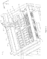
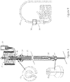
- a fluid transport system 10 for an automated slide treatment apparatus 12 for treating tissue samples disposed on slides 13 is shown in Figure 1 .
- the slide treatment apparatus 12 includes a plurality of slide treatment modules 14 arranged to receive the slides 13, and includes at least one slide transport robot 18, in the form of a gantry robot configured by a controller, to move the slides 13 to and from the slide treatment modules 14.
- the fluid transport system 10 includes a fluid dispensing robot 16 configured by the controller to move to designated slide treatment module 14 to dispense a plurality of reagents to the slides 13 received in the slide treatment modules 14 to treat the tissue samples on the slides 13.
- the slide transport robot 18 is combined with the fluid dispensing robot 16 in a gantry robot, which is configured to move in the x, y and z axes. It will be appreciated by those persons skilled in the art that the slide transport robot 18 can be separate from the fluid dispensing robot 16.
- the slide transport robot 18 is an articulated armed robot while the fluid dispensing robot 16 is a gantry robot, and vice versa.
- the fluid dispensing robot 16 includes a fluid transfer probe (FTP) robot configured by the controller to dispense a plurality of high value reagents stored in reagent containers to the slides 13 in the slide treatment modules 14. Examples of high value reagents include chromogens and antibodies.
- FTP fluid transfer probe
- the gantry robot includes the combined FTP robot 16 and the slide transport robot 18 to minimise the size and complexity of the apparatus 12.
- the x axis is a length of the apparatus 12
- the y axis is a width of the apparatus 12
- the z axis corresponds to a height of the apparatus 12.
- the fluid dispensing robot 16, hereinafter referred to as FTP robot 16, and the slide transport robot 18 are configured by the controller to dispense reagents to slides in the slide treatment modules 14 and to move the slides 13 to and from the slide treatment modules 14.
- the controller of the automated slide treatment apparatus 12 - and the slide transport robot 18 and the FTP robot 16 - can either be implemented remotely from the apparatus 12 or can be implemented locally with respect to the apparatus 12.
- the controller includes a number of modules, implemented by a processor and a memory for storing instructions for the modules, to provide instructions to the slide transport robot 18 and the FTP 16 to control movement thereof and dispensing of reagents.
- the slide transport robot 18 is configured by the controller to move quickly between the different modules in the apparatus 12 in the three axes so as to efficiently move slides in and out of the slide treatment modules 14 so as to treat samples disposed on the slides in the slide treatment modules 14.
- the slide transport robot 18 is configured to move from one corner of the apparatus 12 to the diagonally opposite corner in 2.2 seconds (which represents the maximum move with respect to the apparatus 12).
- the travel profiles for the slide transport robot 18 shown with respect to the apparatus 12 in Figure 1 may be e.g. 780 mm in the x axis, 500 mm in the y axis and 120 mm in the z axis although these ranges are examples only.
- the gantry robot 18, and the FTP robot 16 moves along a rail 21 in the x direction and a rail 19 in the y direction so as to move slides to and from the slide treatment modules 14 and to dispense reagents to the slides 13 in the designated slide treatment modules 14 to treat those samples disposed on the slides.
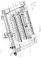
- the apparatus 12 includes two bulk fluid robots (BFRs) 15 configured by the controller to dispense a plurality of lesser value reagents stored in reagent containers to the slides 13 received in the slide treatment modules 14 to also treat tissue samples on the slides. That is, in some cases, to treat the tissue samples on the slides 13, a designated combination and order of high and lesser value, bulk reagents is dispensed to a slide. It will be appreciated by those persons skilled in the art that the apparatus 12 may include more than two BFRs to dispense the lesser value reagents stored in reagent containers to the slides 13.
- the BFRs 15 are configured by the controller to dispense bulk reagents to the slides 13, such as oxalic acid, sulphuric acid, potassium permanganate, alcohol, dewaxing agent, haematoxylin, peroxide, citric acid, EDTA, DI water and Bond TM wash to treat the tissue samples disposed thereon.
- bulk reagents such as oxalic acid, sulphuric acid, potassium permanganate, alcohol, dewaxing agent, haematoxylin, peroxide, citric acid, EDTA, DI water and Bond TM wash to treat the tissue samples disposed thereon.
- the slide transport robot 18 is configured to move the slides 13 to and from the slide treatment modules 14 without interfering with the BFRs 15 as the slide transport robot can move in the z direction.
- the BFRs 15 are configured to move only in the x and z directions to dispense the bulk reagents to the slides 13 in the slide treatment modules 14.
- the slide transport robot 18 also includes a slide transport device 20, shown in Figure 3 , disposed on the slide transport robot 18, which is configured by the controller to releasably hold the slides 13.
- the slide transport device 20 is a suction cup arranged to releasably hold the slide 13 when it is to be moved to a slide treatment module 14 and to release the slide 13 to locate it in a slide treatment module 14.
- the slide transport device 20 is also envisaged to include other means for releasably holding a slide, such as a gripper.
- the slide transport robot 18 includes a slide handling head 22 arranged to move a closure body 24 of one of the slide treatment modules 14 so as to move the closure body 24 normally biased in a closed position to an open position when the slide transport robot is configured by the controller to move one of the slides 13 to the slide treatment module 14.
- the slide transport device 20 also extends from the slide handling head 22 and is configured by a controller to release the slide 13 so as to locate the slide in the slide treatment module 14 when the closure body 24 is held in the open position.
- the FTP robot 16 can then dispense reagents to the slide 13 when the closure body 24 of the slide treatment module 14 reverts back to the closed position after the slide handling head 22 moves in the x axis so as to close the closure body 24.
- the slide transport robot 18 is described in more detail in the co-pending US provisional patent application entitled "A Slide Transport System”.
- the FTP robot 16 forces fluid into or withdraws fluid from a reaction chamber to achieve agitation and/or evacuation of reagent from the reaction chamber. Agitation can facilitate mixing of reagent and/or assist with bubble management within the reaction chamber during a processing step, increasing the likelihood of reagent contacting a sample on the substrate despite the existence of bubbles in the chamber.
- Reagent dispensing and withdrawal may be coupled with a pressure and/or vacuum or other source configured to apply negative and/or positive fluid pressures.
- Figures 1 and 2 also show the automated slide treatment apparatus 12 having input and output buffer modules 17, whereby the input buffer module 17 introduces slides 13 to the apparatus 12 for treatment and the output buffer module 17 allows for the removal of the slides from the apparatus 12 after treatment of the tissue samples on the slides 13.
- the slide transport robot 18 of the embodiment shown in these figures is thus further configured to retrieve a slide from the input module 17 and locate it in a slide treatment module 14 and to remove the slide 13 from the slide treatment module 14 and locate it in the output module 17 after the tissue samples disposed on the slide have been treated with the FTP robot 16 and/or the BFR 15.
- the slide transport robot 18 of the embodiment can also be configured to move the slide to/from other modules (not shown) for performing other operations on the slide, such as coverslipping and digital imaging modules, before moving the slide to the output module.
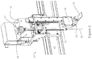
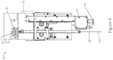
- FIGS. 3 and 4 show the FTP robot 16 in further detail.
- the FTP robot 16 is configured to move along the rail 21 in the x axis and along a rack 23 in the z axis so as to locate a probe 25 of the fluid dispensing robot 16 at the designated slide treatment module 14 to dispense the designated reagents to the slide 13 received in the designated slide treatment module 14.
- the rack 23 is driven by a pinion on the FTP robot 16 to lower and raise the probe 25 in the z axis. That is, the probe 25 can be raised or lowered in the z axis so that the reagents can be dispensed to the slide 13 in the slide treatment module 14 when the closure body 24 of the slide treatment module 14 is in the closed position.
- the FTP robot 16 moves along the rail 21 and the rail 19 in the x and y axes using a chain drive system driven by stepper motors. Nonetheless, it will be appreciated by those persons skilled in the art that other drive systems may be employed, such as another further rack and pinion or belt drive system, pneumatic, solenoid, or leadscrew systems.
- the FTP robot 16 includes a pumping means (not shown) configured by the controller to pump reagents to be dispensed from a plurality of corresponding reagent containers by the probe 25 of the FTP robot 16.
- the pumping means is a syringe pump configured to aspirate the reagents from the reagent containers to be dispensed.
- Figure 2 shows a plurality of high value reagent containers 31 storing high value reagents for dispensing. It will be appreciated by those persons skilled in the art that the pumping means can be located on the FTP robot 16 or somewhere else on the apparatus 12.
- the syringe pumping means aspirates and dispenses high value reagents to/from a nozzle 26 disposed at one end of the probe 25 of the FTP robot 16 from the high value reagent containers 31. That is, the nozzle 26 is lowered by the stepper motor on the rack 23 of the FTP robot 16 into the designated reagent containers so that the reagents can be aspirated via action of the pumping means into the probe 25.
- the sequence of aspirating and dispensing reagents is predetermined to treat the particular tissue samples disposed on the slides.
- the probe 25 of the FTP robot 16 has an elongated body arranged to store one or more of the reagents pumped via the pumping means so as to prime the probe with the reagents to be dispensed.
- the reagents are pumped to the probe 25 of the FTP robot 16 to be dispensed to one or more slides 13 in different slide treatment modules 14.
- the FTP robot 16 has a well 27, disposed on the body of the probe 25, arranged to store further of the reagents so as to increase a volume of the reagents primed to be dispensed.
- the probe 25 dispenses the primed reagents to a number of designated slides 13 received in designated slide treatment modules 14 without having to further aspirate and pump reagents into the probe 25. That is, without having to move the nozzle 26 of the probe 25 back to the high value reagent containers to prime the probe 25 and the well 27 again.
- the pumping means can be further configured by the controller to pump and/or aspirate more than one of the reagents from different ones of reagent containers successively with an air gap between successive reagents so as to prime the probe with a plurality of different reagents.
- the FTP 16 robot can dispense different reagents to the same or different slides at different stages of their slide treatment protocol without having to return to the reagent containers 31 to aspirate further reagents.
- the nozzle 26 of the probe 25 is located adjacent the slide handling head 22 of the slide transport robot 18, which is arranged to contact against a bearing surface of the closure body 24 of a slide treatment module 14 to move the closure body 24 to the open position so that a slide 13 can be located therein for treatment. That is, the slide handling head 22 contacts against the bearing surface when the slide transport robot 18 moves the closure body 24 to the open position, by resisting the bias and then back to the closed position.
- the nozzle 26 of the probe 25 can then be lowered in the z axis to dispense reagents to the slide 13.
- the slide treatment modules 14 are aligned in the apparatus 12 so as to be opened in the x direction to minimise the amount of movement for the slide transport robot 18 and the FTP robot 16.
- Figures 6 to 9 show the probe 25 and the well 27 of the fluid transport system 10 in more detail.
- Figure 5 shows the probe 25 without the well 27, where only the elongated body of the probe 25 is arranged to store reagents therein so as to prime the probe 25 with reagents.
- Figures 6 and 7 show the well 27 for further storing reagents to increase the volume of reagents to be primed to be dispensed.
- the well 27 is a coiled tube of substantially similar diameter to the elongate tube of the body of the probe 25 to substantially increase the volume of reagents to be primed for dispensing to the slides 13 and to minimise the size of the probe 25.
- the well 27 may take different forms, such as a tank, and need not be located at the end of the probe 25.
- the well 27 could be a tank located at some point along the body of the probe 25.
- the coiled tube of the well 27 is also removeably attached to a reagent line connected to the pumping means at a resealable connector 28.
- the connector 28 connects a flexible, tubular reagent line 40 to the well 27 via a plug 38 which creates a sealing fit with the connector 28.
- the body of the probe 25 is removeably attached to the FTP robot 16 using electrically insulating probe collars; specifically, a bottom collar in the form of a plastic collet 30 and a top collar in the form of a plastic clip 32 to hold the probe 25 in position and to insulate the probe 25 from the tubular rack 23.
- the probe 25 also has locating blocks 29 to locate and lock the probe 25 in the rack 23 using the collet 30 and the clip 32, as shown in more detail in Figure 8 .
- the probe 25 is mounted from the top of the tubular rack 23 and through the rack 23.
- a spring 36 and two plastic spacers locate and lock the probe 25 in position at the top of the rack 23.
- the rack 23 has a finger grip 34 arranged to slide relative to the rack 23 to remove the clip 32 from the rack 23 to remove the probe 25 from the rack 23.
- the collet 30 is inserted into the gap between the tubular rack 23 and the probe 25 and held in place by the locating blocks 29 on the probe 25 to lock the probe 25 in position at the bottom of the rack 23.
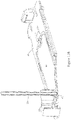
- FIG 13 shows a schematic diagram of the fluid transport system 10 described above from the nozzle 26 of the probe 25 to the syringe pump C and, in this case, a wash pump D. It should be understood, however, that there may be multiple wash pumps D feeding into the syringe C which may also comprise a bypass valve.
- a reagent line extends between the well 27 of the probe 25 and the syringe pump C via a pressure sensor B.
- the syringe C may be bypassed altogether by bypass valve C so that the one or more wash pumps D feed feed directly into the probe (see Figure 12B ).
- An example of the dimensions of the components of the system 10 with reference to this figure is as follows.
- the distance is 120mm.
- the diameter of this dispensing end of the probe 25 from point a to A is 1.3mm and the volume is 150 ⁇ l.
- the diameter of the body of the probe 25 from point A to the pressure sensor B and the diameter of the coiled tube of the well 27 is 2mm.
- the length of tube of the well 27 combined with the length of the elongate body of the probe 25 volume is 1100mm and the volume is 3500 ⁇ l.
- the amount of reagent primed to be dispensed in the body of the probe 25 and the well 27, as well as the reagent line to the pressure sensor has a maximum volume of 3650 ⁇ l.
- the reagent line from the pressure sensor B to the syringe pump C is a plastic tube having a diameter of 2mm and a length of 2500mm.
- the length of the elongate body of the probe 25 enhances the provision of gaps, such as an air gap, to substantially separate different reagents drawn into the probe.
- the pressure sensor B senses pressure in the reagent line to confirm that reagents have been dispensed from the probe 25.
- the sensing means is a liquid level sensor for sensing an amount of dispensed reagent from the probe 25.
- the liquid level sensor can be a capacitive liquid level sensor configured to monitor for changes in capacitance at the nozzle 26 of the probe 25 or it can be a pressure liquid level sensor configured to sense changes in pressure at the nozzle 26.
- optical liquid level sensing systems and ultrasonic systems may be employed.
- the connector 28, clip 32 and collet 30 are made from an electrically insulating material, such as rubber or plastic, to electrically isolate the coiled tube and the body of the probe 25 from the other components of the FTP robot 16, such as the rack 23, so that the capacitive measurements can be made without interference from the other components.
- the closure body 24 of the slide treatment module 14 creates a sealed reaction chamber for treating tissue samples on the slide 13 with a cover member 42, shown in Figures 10A and 10B , of the slide treatment module 14.
- the cover member 42 is disposed on the underside of the closure body 24 and is arranged to form the sealed reaction chamber with the slide 13 when the closure body 24 is in the closed position after the slide transport robot 18 has located the slide 13 in the slide treatment module 14. Details of the cover member 42 are described in the co-pending US provisional patent application entitled "Slide Staining Assembly and Cover Member".
- the FTP robot 16 and the BFR 15 can then dispense reagents to the slide 13 in the slide treatment module 14 when the closure body 24 is in the closed position in the designated order and with designated volumes to treat the tissue samples on the slides 13.
- the instructions for the designated reagents and the order that the reagents are to be dispensed can be stored in a memory in data communication with the controller.
- the nozzle 26 of the probe 25 is arranged to couple with a receiving portion 44 of the cover member 42 in the slide treatment module 14, and substantially sealingly mate with an inlet port 43 in the receiving portion 44 of the cover member 42 whilst the reagents are being dispensed.
- the FTP robot 16 includes a driver means, such as the above described stepper motor, to urge the nozzle 26 of the probe 25 in the z axis towards the inlet port 43 of the slide treatment module 14 whilst the reagents are being dispensed to maintain a seal with the inlet port 43.
- the driving means exerts a 5 to 30N force, such as, for example a 10N force on the probe 25 to urge the nozzle 26 of the probe 25 towards the inlet port 43 using a stepper motor in constant torque mode.
- a 5 to 30N force such as, for example a 10N force on the probe 25 to urge the nozzle 26 of the probe 25 towards the inlet port 43 using a stepper motor in constant torque mode.
- the inlet port 43 may have a chamfer, such as 30 to 75 degree, for example a 60 degree chamfer to guide and to seal with the nozzle 26 of the probe 25.
- the apparatus 12 includes a wash drum 49 of a wash station 48 for washing the probe 25 when the probe is inserted into the wash drum 49 of the wash station 48 via movement of the FTP robot 16 as described above. Furthermore, as shown in Figure 13 , the syringe pump C is connected to the wash pump D via a wash line so that the reagent lines of the FTP robot 16 can be washed with wash fluid, such as Bond TM wash, DI water and alcohol pumped from the wash pump D.
- wash fluid such as Bond TM wash, DI water and alcohol pumped from the wash pump D.
- the wash pump D may be supplied by a fluid delivery line suitable for the delivery of fluids, such as hydraulic fluid or fluids, including, but not limited to one or more of wash solution, water, buffer, diluent such as antibody diluent, cleaning solution and the like.
- the wash pump may be supplied by a plurality of fluid delivery lines suitable for the delivery of fluids.
- the wash pump D is configured to pump wash fluid to a wash fluid injection port 50 by the controller from one or more wash fluid containers.
- the wash fluid then passes over a textured surface 52 to create a turbulent flow of the wash fluid over the probe 25 when it is inserted into the wash drum 49.
- the textured surface 52 includes spiral corrugations in the wash drum in the form of a spiral wash rings to create the turbulent flow to wash the probe 25.
- the wash drum 49 also includes a collection chamber 54 and scavenging port 56 to collect and remove the wash fluid from the wash drum 49. It will be appreciated by those persons skilled in the art that the wash fluid may be recycled and reused by the wash pump.
- the wash drum 49 includes an inlet port 55 and an outlet port 57 for circulating air past the nozzle 26 of the probe 25 to improve the washing process.
- a vacuum means is applied to the outlet port 57 so that air is drawn out of the outlet port 57 and in through the inlet port 55 so that it travels around the probe 25 when it is inserted into the wash drum 49.
- the air is forced though the inlet port from the atmosphere in this embodiment.
- Seal 60 prevents air from being drawn into the wash drum 49 around probe 25.
- wash fluid is injected via probe 25 into the wash drum 49 using the wash pump D and the vacuum is applied so that air from the inlet port 55 mixes with the wash fluid around the probe 25 to aid in cleaning the probe 25.
- a closed system could be employed to wash the probe 25 and, for instance, a captive inert gas is used instead of air.
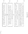
- FIG. 14 there is shown a summary of a method 100 of transporting fluid for treatment of one or more tissue samples disposed on slides, whereby ones of the slides are received in a plurality of slide treatment modules and a plurality of fluid reagents are dispensed by at least one fluid dispensing robot to the slides received in the slide treatment modules to treat the tissue samples on the slides.
- the method 100 includes the steps of pumping 102 the reagents to be dispensed from a plurality of corresponding reagent containers, storing 104 one or more of the reagents pumped from the corresponding reagent containers in a body of a probe so as to prime the probe with said one or more of the reagents to be dispensed, further storing 106 said one or more of the reagents in a well disposed on the body of the probe so as to increase a volume of the one or more of the reagents primed to be dispensed, and dispensing 108 said one or more of the reagents primed to be dispensed to the slides received in the slide treatment modules.
Applications Claiming Priority (2)
| Application Number | Priority Date | Filing Date | Title |
|---|---|---|---|
| US201261721269P | 2012-11-01 | 2012-11-01 | |
| PCT/AU2013/001264 WO2014066947A1 (en) | 2012-11-01 | 2013-11-01 | A fluid transport system |
Publications (3)
| Publication Number | Publication Date |
|---|---|
| EP2914950A1 EP2914950A1 (en) | 2015-09-09 |
| EP2914950A4 EP2914950A4 (en) | 2016-07-20 |
| EP2914950B1 true EP2914950B1 (en) | 2023-01-04 |
Family
ID=50626221
Family Applications (1)
| Application Number | Title | Priority Date | Filing Date |
|---|---|---|---|
| EP13850113.5A Active EP2914950B1 (en) | 2012-11-01 | 2013-11-01 | An automated slide treatment apparatus |
Country Status (6)
| Country | Link |
|---|---|
| US (1) | US10228382B2 (ja) |
| EP (1) | EP2914950B1 (ja) |
| JP (1) | JP6346191B2 (ja) |
| CN (2) | CN110243653A (ja) |
| AU (1) | AU2013337608B2 (ja) |
| WO (1) | WO2014066947A1 (ja) |
Families Citing this family (19)
| Publication number | Priority date | Publication date | Assignee | Title |
|---|---|---|---|---|
| US11395897B1 (en) | 2014-06-27 | 2022-07-26 | Orlando Morejon | Connector assembly for a medical ventilator system |
| EP3286526B1 (en) | 2015-04-21 | 2019-10-09 | Fisher Controls International Llc | Systems and methods for detecting lever locking positions on liquid level controllers |
| US10837977B2 (en) | 2015-05-11 | 2020-11-17 | Kabushiki Kaisha Yaskawa Denki | Rack for dispensing and dispensing system |
| WO2016181466A1 (ja) * | 2015-05-11 | 2016-11-17 | 株式会社安川電機 | 分注システム、コントローラ及び制御方法 |
| CN107044922A (zh) * | 2017-01-20 | 2017-08-15 | 广东顺德工业设计研究院(广东顺德创新设计研究院) | 取样装置 |
| JP6814074B2 (ja) * | 2017-03-08 | 2021-01-13 | オルガノ株式会社 | 洗浄液の汚染監視方法、洗浄液の汚染監視システム及び洗浄液精製装置 |
| WO2019017902A1 (en) * | 2017-07-18 | 2019-01-24 | Hewlett-Packard Development Company, L.P. | EXCHANGEABLE REAGENT MODULES |
| FR3072171B1 (fr) * | 2017-10-06 | 2021-02-19 | Diagdev | Dispositif et procede de coloration d'un element organique sur une lame |
| AU2018390983B2 (en) * | 2017-12-21 | 2023-11-30 | Leica Biosystems Melbourne Pty Ltd | A fluid transport system |
| CN108088726B (zh) * | 2018-02-08 | 2020-12-22 | 爱威科技股份有限公司 | 一种多功能任选染色装置 |
| WO2020053042A1 (en) * | 2018-09-11 | 2020-03-19 | Koninklijke Philips N.V. | Optical method for gingivitis detection |
| EP3841387A4 (en) * | 2018-12-20 | 2021-11-17 | Leica Biosystems Melbourne Pty Ltd | BULK FLUID WASHING MODULE |
| KR102299717B1 (ko) * | 2020-01-22 | 2021-09-08 | 주식회사 임진과학 | 시약을 자동으로 공급하기 위한 시약공급장치 |
| US20230213542A1 (en) * | 2020-07-29 | 2023-07-06 | Siemens Healthcare Diagnostics Inc. | A helix wash station that augments the fluid dynamics associated with clinical chemistry and immunoassay probe cleaning |
| EP4217399A1 (en) | 2020-09-22 | 2023-08-02 | Roche Diagnostics GmbH | Antibodies specific for alpha-1,6-core-fucosylated psa and fucosylated fragments thereof |
| CN112113818A (zh) * | 2020-10-09 | 2020-12-22 | 嘉兴晶铸生物科技有限公司 | 一种恒温全自动化细胞制片一体化装置及制片方法 |
| US11809157B2 (en) | 2021-03-22 | 2023-11-07 | Fisher Controls International Llc | Level sensor for continuous level detection and integration into process control system |
| CN113484105A (zh) * | 2021-07-03 | 2021-10-08 | 南京盛航海运股份有限公司 | 船舶舱位气体监测系统 |
| EP4317989A1 (en) * | 2022-08-02 | 2024-02-07 | Beckman Coulter, Inc. | Capacitive detection device and methods |
Citations (3)
| Publication number | Priority date | Publication date | Assignee | Title |
|---|---|---|---|---|
| JPS58163870U (ja) * | 1982-04-28 | 1983-10-31 | オリンパス光学工業株式会社 | 自動分析機のノズル洗浄槽 |
| EP0810438A2 (en) * | 1996-05-31 | 1997-12-03 | Packard Instrument Company, Inc. | Microvolume liquid handling system |
| US6673620B1 (en) * | 1999-04-20 | 2004-01-06 | Cytologix Corporation | Fluid exchange in a chamber on a microscope slide |
Family Cites Families (55)
| Publication number | Priority date | Publication date | Assignee | Title |
|---|---|---|---|---|
| US3495926A (en) * | 1966-11-02 | 1970-02-17 | John F Naz | Method and apparatus for staining microslides |
| US3915652A (en) * | 1973-08-16 | 1975-10-28 | Samuel Natelson | Means for transferring a liquid in a capillary open at both ends to an analyzing system |
| US3859051A (en) * | 1973-08-16 | 1975-01-07 | Rohe Scientific Corp | Means for transferring a liquid in a capillary open at both ends to an analyzing system |
| US4794085A (en) * | 1984-07-19 | 1988-12-27 | Eastman Kodak Company | Apparatus and method for detecting liquid penetration by a container used for aspirating and dispensing the liquid |
| JPS61202165A (ja) * | 1985-03-05 | 1986-09-06 | Minoru Atake | 液体の計量方式 |
| US4730631A (en) * | 1985-07-22 | 1988-03-15 | Sequoia-Turner Corporation | Probe wash station |
| JP2834787B2 (ja) * | 1989-09-25 | 1998-12-14 | 株式会社千代田製作所 | 染色装置と染色用トレー |
| US5346672A (en) * | 1989-11-17 | 1994-09-13 | Gene Tec Corporation | Devices for containing biological specimens for thermal processing |
| JPH087222B2 (ja) * | 1990-01-18 | 1996-01-29 | 持田製薬株式会社 | 自動分注希釈装置 |
| CA2044295A1 (en) * | 1990-06-22 | 1991-12-23 | Walter Fassbind | Coupling device for pipetting needle |
| US5085832A (en) * | 1990-07-20 | 1992-02-04 | Eastman Kodak Company | Dispensing mechanism |
| JPH06508216A (ja) * | 1991-12-13 | 1994-09-14 | デイド、ベーリング、インコーポレイテッド | 液体分析装置のためのプローブ洗浄 |
| JP3320444B2 (ja) * | 1992-04-06 | 2002-09-03 | 株式会社千代田製作所 | 染色装置用ノズル洗浄装置 |
| JP3237799B2 (ja) * | 1993-04-06 | 2001-12-10 | オリンパス光学工業株式会社 | 多種液体用連続処理具の自動洗浄装置 |
| JPH07218513A (ja) | 1994-02-01 | 1995-08-18 | Aloka Co Ltd | ノズル洗浄方法 |
| US5725831A (en) * | 1994-03-14 | 1998-03-10 | Becton Dickinson And Company | Nucleic acid amplification apparatus |
| CA2143365A1 (en) * | 1994-03-14 | 1995-09-15 | Hugh V. Cottingham | Nucleic acid amplification method and apparatus |
| US5578270A (en) * | 1995-03-24 | 1996-11-26 | Becton Dickinson And Company | System for nucleic acid based diagnostic assay |
| JP3976356B2 (ja) * | 1995-03-31 | 2007-09-19 | シスメックス株式会社 | 自動標本作製装置 |
| US5800784A (en) * | 1996-07-09 | 1998-09-01 | Horn; Marcus J. | Chemical sample treatment system and cassette, and methods for effecting multistep treatment process |
| US6045755A (en) * | 1997-03-10 | 2000-04-04 | Trega Biosciences,, Inc. | Apparatus and method for combinatorial chemistry synthesis |
| EP1007973B1 (en) | 1997-04-08 | 2004-12-01 | Packard Instrument Company, Inc. | Microvolume liquid handling system |
| US6489171B1 (en) * | 1997-04-18 | 2002-12-03 | Cell Marque Corporation | Chemical dispensing system and method |
| US6060320A (en) * | 1997-12-05 | 2000-05-09 | Bayer Corporation | Method of verifying aspirated volume in automatic diagnostic system |
| DE19918442B4 (de) * | 1999-04-23 | 2005-04-14 | Leica Microsystems Nussloch Gmbh | Färbeautomat zum Einfärben von Objekten zur mikroskopischen Untersuchung |
| JP4148778B2 (ja) * | 2001-03-09 | 2008-09-10 | バイオミクロ システムズ インコーポレイティッド | アレイとのミクロ流体的インターフェース機器 |
| JP2005530165A (ja) * | 2002-06-20 | 2005-10-06 | ビジョン・バイオシステムズ・リミテッド | 流体排出機構を備えた生物反応装置 |
| US7850912B2 (en) * | 2003-05-14 | 2010-12-14 | Dako Denmark A/S | Method and apparatus for automated pre-treatment and processing of biological samples |
| US7875245B2 (en) * | 2003-05-14 | 2011-01-25 | Dako Denmark A/S | Method and apparatus for automated pre-treatment and processing of biological samples |
| US7584019B2 (en) * | 2003-12-15 | 2009-09-01 | Dako Denmark A/S | Systems and methods for the automated pre-treatment and processing of biological samples |
| WO2004083824A1 (en) * | 2003-03-20 | 2004-09-30 | Dakocytomation Denmark A/S | System for establishing a sample cover on a substrate |
| JP4103078B2 (ja) * | 2003-07-01 | 2008-06-18 | 日本パルスモーター株式会社 | 定量分与器 |
| US7767152B2 (en) * | 2003-08-11 | 2010-08-03 | Sakura Finetek U.S.A., Inc. | Reagent container and slide reaction retaining tray, and method of operation |
| WO2005066327A1 (en) * | 2004-01-08 | 2005-07-21 | Dako Denmark A/S | Apparatus and methods for processing biological samples and a reservoir therefore |
| JP2007526479A (ja) * | 2004-03-02 | 2007-09-13 | ダコ デンマーク アクティーゼルスカブ | 生物学的染色装置のための試薬送達システム、分配デバイスおよび容器 |
| US7588890B2 (en) * | 2004-04-16 | 2009-09-15 | Wei-Sing Chu | Device for extracting biological molecules from tissue specimens and methods for preparing the same |
| JP2006153785A (ja) * | 2004-12-01 | 2006-06-15 | Hitachi Ltd | 溶液攪拌装置及び分析システム |
| NO321927B1 (no) * | 2004-12-23 | 2006-07-24 | Oystein Ljungmann | Apparat for utforelse av behandlingsoperasjoner pa objektglass med vevsprover |
| JP5335420B2 (ja) * | 2005-05-24 | 2013-11-06 | リー エイチ. アングロス, | insitu熱誘導抗原回復・着色装置および方法 |
| JP4476906B2 (ja) * | 2005-09-02 | 2010-06-09 | 富士フイルム株式会社 | 分注装置 |
| JP4671346B2 (ja) * | 2005-09-13 | 2011-04-13 | キヤノン株式会社 | 液体充填性を向上させた生化学反応カセット |
| WO2008109422A1 (en) * | 2007-03-02 | 2008-09-12 | Becton, Dickinson And Company | Method and apparatus for automated staining of biological materials |
| ES2687620T3 (es) * | 2007-05-04 | 2018-10-26 | Opko Diagnostics, Llc | Dispositivo y método para análisis en sistemas microfluídicos |
| WO2009152569A1 (en) * | 2008-06-16 | 2009-12-23 | Leica Biosystems Melbourne Pty Ltd | Improvements in staining instruments and methods |
| WO2010025425A1 (en) * | 2008-08-29 | 2010-03-04 | Angros Lee H | Multiplexed microscope slide staining apparatus |
| GB0821636D0 (en) * | 2008-11-26 | 2008-12-31 | Ucl Business Plc | Device |
| EP2204686B9 (en) * | 2008-12-30 | 2012-11-14 | Cellavision AB | Analyser for optical analysis of a biological specimen |
| US9573159B2 (en) * | 2009-08-31 | 2017-02-21 | Illinois Tool Works, Inc. | Metering system for simultaneously dispensing two different adhesives from a single metering device or applicator onto a common substrate |
| US8961906B2 (en) * | 2010-07-27 | 2015-02-24 | General Electric Company | Fluid connector devices and methods of making and using the same |
| US8752732B2 (en) * | 2011-02-01 | 2014-06-17 | Sakura Finetek U.S.A., Inc. | Fluid dispensing system |
| WO2013071357A2 (en) * | 2011-11-16 | 2013-05-23 | Leica Biosystems Melbourne Pty Ltd | An automated system and method of treating tissue samples on slides |
| CN104094122B (zh) * | 2011-11-16 | 2017-03-22 | 莱卡生物系统墨尔本私人有限公司 | 用于在基板上处理生物样本的盖元件、方法和处理模块 |
| US8900529B2 (en) * | 2012-04-27 | 2014-12-02 | General Electric Company | Microfluidic chamber device and fabrication |
| EP2914948A4 (en) * | 2012-11-01 | 2016-07-06 | Leica Biosystems Melbourne Pty | SLIDE TRANSPORT SYSTEM |
| CN104884931B (zh) * | 2012-11-01 | 2017-12-12 | 莱卡生物系统墨尔本私人有限公司 | 载玻片染色组件以及盖体部件 |
-
2013
- 2013-11-01 JP JP2015540001A patent/JP6346191B2/ja active Active
- 2013-11-01 AU AU2013337608A patent/AU2013337608B2/en active Active
- 2013-11-01 US US14/439,808 patent/US10228382B2/en active Active
- 2013-11-01 CN CN201910568754.XA patent/CN110243653A/zh active Pending
- 2013-11-01 WO PCT/AU2013/001264 patent/WO2014066947A1/en active Application Filing
- 2013-11-01 EP EP13850113.5A patent/EP2914950B1/en active Active
- 2013-11-01 CN CN201380069051.3A patent/CN104884932A/zh active Pending
Patent Citations (3)
| Publication number | Priority date | Publication date | Assignee | Title |
|---|---|---|---|---|
| JPS58163870U (ja) * | 1982-04-28 | 1983-10-31 | オリンパス光学工業株式会社 | 自動分析機のノズル洗浄槽 |
| EP0810438A2 (en) * | 1996-05-31 | 1997-12-03 | Packard Instrument Company, Inc. | Microvolume liquid handling system |
| US6673620B1 (en) * | 1999-04-20 | 2004-01-06 | Cytologix Corporation | Fluid exchange in a chamber on a microscope slide |
Also Published As
| Publication number | Publication date |
|---|---|
| US10228382B2 (en) | 2019-03-12 |
| AU2013337608B2 (en) | 2017-07-20 |
| CN104884932A (zh) | 2015-09-02 |
| EP2914950A1 (en) | 2015-09-09 |
| WO2014066947A1 (en) | 2014-05-08 |
| JP6346191B2 (ja) | 2018-06-20 |
| US20150276772A1 (en) | 2015-10-01 |
| AU2013337608A1 (en) | 2015-05-21 |
| CN110243653A (zh) | 2019-09-17 |
| EP2914950A4 (en) | 2016-07-20 |
| JP2015533418A (ja) | 2015-11-24 |
Similar Documents
| Publication | Publication Date | Title |
|---|---|---|
| EP2914950B1 (en) | An automated slide treatment apparatus | |
| US20210396776A1 (en) | High-throughput sample processing systems and methods of use | |
| JP5038004B2 (ja) | 分析装置 | |
| EP2780721B1 (en) | Cover member, method and treatment module for treating a biological sample on a substrate | |
| US20170045542A1 (en) | Modular Liquid Handling System | |
| EP2780688B1 (en) | Biological sample treatment apparatus | |
| AU2009260113A1 (en) | Improvements in staining instruments and methods | |
| US20080026472A1 (en) | Instrument For Efficient Treatment Of Analytical Devices | |
| CN107206383B (zh) | 移液器清洁方法和设备、中和液体容器、以及减少残留的方法 | |
| KR20200102977A (ko) | 유체 이송 시스템 | |
| EP1615037A1 (en) | An apparatus for liquid handling with multiple transfer tools | |
| CN107629952B (zh) | 核酸杂交仪 | |
| CN210427577U (zh) | 样本分析系统 | |
| CN112771381A (zh) | 散装流体清洗模块 |
Legal Events
| Date | Code | Title | Description |
|---|---|---|---|
| PUAI | Public reference made under article 153(3) epc to a published international application that has entered the european phase |
Free format text: ORIGINAL CODE: 0009012 |
|
| 17P | Request for examination filed |
Effective date: 20150521 |
|
| AK | Designated contracting states |
Kind code of ref document: A1 Designated state(s): AL AT BE BG CH CY CZ DE DK EE ES FI FR GB GR HR HU IE IS IT LI LT LU LV MC MK MT NL NO PL PT RO RS SE SI SK SM TR |
|
| AX | Request for extension of the european patent |
Extension state: BA ME |
|
| DAX | Request for extension of the european patent (deleted) | ||
| RA4 | Supplementary search report drawn up and despatched (corrected) |
Effective date: 20160620 |
|
| RIC1 | Information provided on ipc code assigned before grant |
Ipc: G01N 1/28 20060101ALI20160614BHEP Ipc: G01N 35/00 20060101ALI20160614BHEP Ipc: G01N 1/31 20060101AFI20160614BHEP |
|
| STAA | Information on the status of an ep patent application or granted ep patent |
Free format text: STATUS: EXAMINATION IS IN PROGRESS |
|
| 17Q | First examination report despatched |
Effective date: 20190917 |
|
| STAA | Information on the status of an ep patent application or granted ep patent |
Free format text: STATUS: EXAMINATION IS IN PROGRESS |
|
| GRAP | Despatch of communication of intention to grant a patent |
Free format text: ORIGINAL CODE: EPIDOSNIGR1 |
|
| STAA | Information on the status of an ep patent application or granted ep patent |
Free format text: STATUS: GRANT OF PATENT IS INTENDED |
|
| INTG | Intention to grant announced |
Effective date: 20220713 |
|
| GRAS | Grant fee paid |
Free format text: ORIGINAL CODE: EPIDOSNIGR3 |
|
| GRAA | (expected) grant |
Free format text: ORIGINAL CODE: 0009210 |
|
| STAA | Information on the status of an ep patent application or granted ep patent |
Free format text: STATUS: THE PATENT HAS BEEN GRANTED |
|
| AK | Designated contracting states |
Kind code of ref document: B1 Designated state(s): AL AT BE BG CH CY CZ DE DK EE ES FI FR GB GR HR HU IE IS IT LI LT LU LV MC MK MT NL NO PL PT RO RS SE SI SK SM TR |
|
| REG | Reference to a national code |
Ref country code: GB Ref legal event code: FG4D |
|
| REG | Reference to a national code |
Ref country code: CH Ref legal event code: EP |
|
| REG | Reference to a national code |
Ref country code: AT Ref legal event code: REF Ref document number: 1542266 Country of ref document: AT Kind code of ref document: T Effective date: 20230115 |
|
| REG | Reference to a national code |
Ref country code: DE Ref legal event code: R096 Ref document number: 602013083183 Country of ref document: DE |
|
| REG | Reference to a national code |
Ref country code: IE Ref legal event code: FG4D |
|
| REG | Reference to a national code |
Ref country code: LT Ref legal event code: MG9D |
|
| REG | Reference to a national code |
Ref country code: NL Ref legal event code: MP Effective date: 20230104 |
|
| REG | Reference to a national code |
Ref country code: AT Ref legal event code: MK05 Ref document number: 1542266 Country of ref document: AT Kind code of ref document: T Effective date: 20230104 |
|
| PG25 | Lapsed in a contracting state [announced via postgrant information from national office to epo] |
Ref country code: NL Free format text: LAPSE BECAUSE OF FAILURE TO SUBMIT A TRANSLATION OF THE DESCRIPTION OR TO PAY THE FEE WITHIN THE PRESCRIBED TIME-LIMIT Effective date: 20230104 |
|
| P01 | Opt-out of the competence of the unified patent court (upc) registered |
Effective date: 20230525 |
|
| PG25 | Lapsed in a contracting state [announced via postgrant information from national office to epo] |
Ref country code: RS Free format text: LAPSE BECAUSE OF FAILURE TO SUBMIT A TRANSLATION OF THE DESCRIPTION OR TO PAY THE FEE WITHIN THE PRESCRIBED TIME-LIMIT Effective date: 20230104 Ref country code: PT Free format text: LAPSE BECAUSE OF FAILURE TO SUBMIT A TRANSLATION OF THE DESCRIPTION OR TO PAY THE FEE WITHIN THE PRESCRIBED TIME-LIMIT Effective date: 20230504 Ref country code: NO Free format text: LAPSE BECAUSE OF FAILURE TO SUBMIT A TRANSLATION OF THE DESCRIPTION OR TO PAY THE FEE WITHIN THE PRESCRIBED TIME-LIMIT Effective date: 20230404 Ref country code: LV Free format text: LAPSE BECAUSE OF FAILURE TO SUBMIT A TRANSLATION OF THE DESCRIPTION OR TO PAY THE FEE WITHIN THE PRESCRIBED TIME-LIMIT Effective date: 20230104 Ref country code: LT Free format text: LAPSE BECAUSE OF FAILURE TO SUBMIT A TRANSLATION OF THE DESCRIPTION OR TO PAY THE FEE WITHIN THE PRESCRIBED TIME-LIMIT Effective date: 20230104 Ref country code: HR Free format text: LAPSE BECAUSE OF FAILURE TO SUBMIT A TRANSLATION OF THE DESCRIPTION OR TO PAY THE FEE WITHIN THE PRESCRIBED TIME-LIMIT Effective date: 20230104 Ref country code: ES Free format text: LAPSE BECAUSE OF FAILURE TO SUBMIT A TRANSLATION OF THE DESCRIPTION OR TO PAY THE FEE WITHIN THE PRESCRIBED TIME-LIMIT Effective date: 20230104 Ref country code: AT Free format text: LAPSE BECAUSE OF FAILURE TO SUBMIT A TRANSLATION OF THE DESCRIPTION OR TO PAY THE FEE WITHIN THE PRESCRIBED TIME-LIMIT Effective date: 20230104 |
|
| PG25 | Lapsed in a contracting state [announced via postgrant information from national office to epo] |
Ref country code: SE Free format text: LAPSE BECAUSE OF FAILURE TO SUBMIT A TRANSLATION OF THE DESCRIPTION OR TO PAY THE FEE WITHIN THE PRESCRIBED TIME-LIMIT Effective date: 20230104 Ref country code: PL Free format text: LAPSE BECAUSE OF FAILURE TO SUBMIT A TRANSLATION OF THE DESCRIPTION OR TO PAY THE FEE WITHIN THE PRESCRIBED TIME-LIMIT Effective date: 20230104 Ref country code: IS Free format text: LAPSE BECAUSE OF FAILURE TO SUBMIT A TRANSLATION OF THE DESCRIPTION OR TO PAY THE FEE WITHIN THE PRESCRIBED TIME-LIMIT Effective date: 20230504 Ref country code: GR Free format text: LAPSE BECAUSE OF FAILURE TO SUBMIT A TRANSLATION OF THE DESCRIPTION OR TO PAY THE FEE WITHIN THE PRESCRIBED TIME-LIMIT Effective date: 20230405 Ref country code: FI Free format text: LAPSE BECAUSE OF FAILURE TO SUBMIT A TRANSLATION OF THE DESCRIPTION OR TO PAY THE FEE WITHIN THE PRESCRIBED TIME-LIMIT Effective date: 20230104 |
|
| REG | Reference to a national code |
Ref country code: DE Ref legal event code: R097 Ref document number: 602013083183 Country of ref document: DE |
|
| PG25 | Lapsed in a contracting state [announced via postgrant information from national office to epo] |
Ref country code: SM Free format text: LAPSE BECAUSE OF FAILURE TO SUBMIT A TRANSLATION OF THE DESCRIPTION OR TO PAY THE FEE WITHIN THE PRESCRIBED TIME-LIMIT Effective date: 20230104 Ref country code: RO Free format text: LAPSE BECAUSE OF FAILURE TO SUBMIT A TRANSLATION OF THE DESCRIPTION OR TO PAY THE FEE WITHIN THE PRESCRIBED TIME-LIMIT Effective date: 20230104 Ref country code: EE Free format text: LAPSE BECAUSE OF FAILURE TO SUBMIT A TRANSLATION OF THE DESCRIPTION OR TO PAY THE FEE WITHIN THE PRESCRIBED TIME-LIMIT Effective date: 20230104 Ref country code: DK Free format text: LAPSE BECAUSE OF FAILURE TO SUBMIT A TRANSLATION OF THE DESCRIPTION OR TO PAY THE FEE WITHIN THE PRESCRIBED TIME-LIMIT Effective date: 20230104 Ref country code: CZ Free format text: LAPSE BECAUSE OF FAILURE TO SUBMIT A TRANSLATION OF THE DESCRIPTION OR TO PAY THE FEE WITHIN THE PRESCRIBED TIME-LIMIT Effective date: 20230104 |
|
| PGFP | Annual fee paid to national office [announced via postgrant information from national office to epo] |
Ref country code: GB Payment date: 20230907 Year of fee payment: 11 |
|
| PLBE | No opposition filed within time limit |
Free format text: ORIGINAL CODE: 0009261 |
|
| STAA | Information on the status of an ep patent application or granted ep patent |
Free format text: STATUS: NO OPPOSITION FILED WITHIN TIME LIMIT |
|
| PG25 | Lapsed in a contracting state [announced via postgrant information from national office to epo] |
Ref country code: SK Free format text: LAPSE BECAUSE OF FAILURE TO SUBMIT A TRANSLATION OF THE DESCRIPTION OR TO PAY THE FEE WITHIN THE PRESCRIBED TIME-LIMIT Effective date: 20230104 |
|
| PGFP | Annual fee paid to national office [announced via postgrant information from national office to epo] |
Ref country code: FR Payment date: 20230911 Year of fee payment: 11 |
|
| 26N | No opposition filed |
Effective date: 20231005 |
|
| PG25 | Lapsed in a contracting state [announced via postgrant information from national office to epo] |
Ref country code: SI Free format text: LAPSE BECAUSE OF FAILURE TO SUBMIT A TRANSLATION OF THE DESCRIPTION OR TO PAY THE FEE WITHIN THE PRESCRIBED TIME-LIMIT Effective date: 20230104 |
|
| PGFP | Annual fee paid to national office [announced via postgrant information from national office to epo] |
Ref country code: DE Payment date: 20230906 Year of fee payment: 11 |