EP2914159B1 - Systèmes et procédés de fourniture d'alarmes sensibles et spécifiques - Google Patents
Systèmes et procédés de fourniture d'alarmes sensibles et spécifiques Download PDFInfo
- Publication number
- EP2914159B1 EP2914159B1 EP13784079.9A EP13784079A EP2914159B1 EP 2914159 B1 EP2914159 B1 EP 2914159B1 EP 13784079 A EP13784079 A EP 13784079A EP 2914159 B1 EP2914159 B1 EP 2914159B1
- Authority
- EP
- European Patent Office
- Prior art keywords
- user
- criteria
- glucose
- alert
- function
- Prior art date
- Legal status (The legal status is an assumption and is not a legal conclusion. Google has not performed a legal analysis and makes no representation as to the accuracy of the status listed.)
- Active
Links
- 238000000034 method Methods 0.000 title claims description 65
- WQZGKKKJIJFFOK-GASJEMHNSA-N Glucose Natural products OC[C@H]1OC(O)[C@H](O)[C@@H](O)[C@@H]1O WQZGKKKJIJFFOK-GASJEMHNSA-N 0.000 claims description 406
- 239000008103 glucose Substances 0.000 claims description 406
- 230000002218 hypoglycaemic effect Effects 0.000 claims description 129
- NOESYZHRGYRDHS-UHFFFAOYSA-N insulin Chemical compound N1C(=O)C(NC(=O)C(CCC(N)=O)NC(=O)C(CCC(O)=O)NC(=O)C(C(C)C)NC(=O)C(NC(=O)CN)C(C)CC)CSSCC(C(NC(CO)C(=O)NC(CC(C)C)C(=O)NC(CC=2C=CC(O)=CC=2)C(=O)NC(CCC(N)=O)C(=O)NC(CC(C)C)C(=O)NC(CCC(O)=O)C(=O)NC(CC(N)=O)C(=O)NC(CC=2C=CC(O)=CC=2)C(=O)NC(CSSCC(NC(=O)C(C(C)C)NC(=O)C(CC(C)C)NC(=O)C(CC=2C=CC(O)=CC=2)NC(=O)C(CC(C)C)NC(=O)C(C)NC(=O)C(CCC(O)=O)NC(=O)C(C(C)C)NC(=O)C(CC(C)C)NC(=O)C(CC=2NC=NC=2)NC(=O)C(CO)NC(=O)CNC2=O)C(=O)NCC(=O)NC(CCC(O)=O)C(=O)NC(CCCNC(N)=N)C(=O)NCC(=O)NC(CC=3C=CC=CC=3)C(=O)NC(CC=3C=CC=CC=3)C(=O)NC(CC=3C=CC(O)=CC=3)C(=O)NC(C(C)O)C(=O)N3C(CCC3)C(=O)NC(CCCCN)C(=O)NC(C)C(O)=O)C(=O)NC(CC(N)=O)C(O)=O)=O)NC(=O)C(C(C)CC)NC(=O)C(CO)NC(=O)C(C(C)O)NC(=O)C1CSSCC2NC(=O)C(CC(C)C)NC(=O)C(NC(=O)C(CCC(N)=O)NC(=O)C(CC(N)=O)NC(=O)C(NC(=O)C(N)CC=1C=CC=CC=1)C(C)C)CC1=CN=CN1 NOESYZHRGYRDHS-UHFFFAOYSA-N 0.000 claims description 128
- 230000008859 change Effects 0.000 claims description 117
- 239000012491 analyte Substances 0.000 claims description 83
- 102000004877 Insulin Human genes 0.000 claims description 64
- 108090001061 Insulin Proteins 0.000 claims description 64
- 229940125396 insulin Drugs 0.000 claims description 64
- 239000008280 blood Substances 0.000 claims description 46
- 210000004369 blood Anatomy 0.000 claims description 46
- 230000008569 process Effects 0.000 claims description 34
- 238000012545 processing Methods 0.000 claims description 28
- 238000012384 transportation and delivery Methods 0.000 claims description 27
- 208000013016 Hypoglycemia Diseases 0.000 claims description 25
- 230000001965 increasing effect Effects 0.000 claims description 17
- 230000000007 visual effect Effects 0.000 claims description 15
- 230000003068 static effect Effects 0.000 claims description 13
- 201000001421 hyperglycemia Diseases 0.000 claims description 12
- 238000004458 analytical method Methods 0.000 claims description 10
- 238000013528 artificial neural network Methods 0.000 claims description 10
- 238000006243 chemical reaction Methods 0.000 claims description 9
- 238000012937 correction Methods 0.000 claims description 8
- 238000001356 surgical procedure Methods 0.000 claims description 4
- 230000000977 initiatory effect Effects 0.000 claims description 3
- 230000007704 transition Effects 0.000 description 99
- 230000006870 function Effects 0.000 description 83
- 230000003345 hyperglycaemic effect Effects 0.000 description 81
- 238000012544 monitoring process Methods 0.000 description 72
- 230000007420 reactivation Effects 0.000 description 46
- 230000002641 glycemic effect Effects 0.000 description 42
- 235000012054 meals Nutrition 0.000 description 25
- 230000001960 triggered effect Effects 0.000 description 24
- 230000004913 activation Effects 0.000 description 23
- 230000015654 memory Effects 0.000 description 20
- 230000009471 action Effects 0.000 description 19
- 238000004891 communication Methods 0.000 description 17
- 206010012601 diabetes mellitus Diseases 0.000 description 17
- 230000002779 inactivation Effects 0.000 description 17
- 230000001133 acceleration Effects 0.000 description 15
- 230000004044 response Effects 0.000 description 14
- 238000011084 recovery Methods 0.000 description 13
- 230000003213 activating effect Effects 0.000 description 12
- 238000005259 measurement Methods 0.000 description 11
- 238000013500 data storage Methods 0.000 description 8
- 238000001514 detection method Methods 0.000 description 8
- 230000000875 corresponding effect Effects 0.000 description 7
- 238000011156 evaluation Methods 0.000 description 7
- 238000004364 calculation method Methods 0.000 description 6
- 230000000630 rising effect Effects 0.000 description 6
- 230000005540 biological transmission Effects 0.000 description 5
- 210000004027 cell Anatomy 0.000 description 5
- 230000003993 interaction Effects 0.000 description 5
- RLLPVAHGXHCWKJ-UHFFFAOYSA-N permethrin Chemical compound CC1(C)C(C=C(Cl)Cl)C1C(=O)OCC1=CC=CC(OC=2C=CC=CC=2)=C1 RLLPVAHGXHCWKJ-UHFFFAOYSA-N 0.000 description 5
- 238000002560 therapeutic procedure Methods 0.000 description 5
- 238000001914 filtration Methods 0.000 description 4
- 230000007246 mechanism Effects 0.000 description 4
- 238000005070 sampling Methods 0.000 description 4
- 230000035882 stress Effects 0.000 description 4
- CSCPPACGZOOCGX-UHFFFAOYSA-N Acetone Chemical compound CC(C)=O CSCPPACGZOOCGX-UHFFFAOYSA-N 0.000 description 3
- 208000003443 Unconsciousness Diseases 0.000 description 3
- 230000008901 benefit Effects 0.000 description 3
- WQZGKKKJIJFFOK-VFUOTHLCSA-N beta-D-glucose Chemical compound OC[C@H]1O[C@@H](O)[C@H](O)[C@@H](O)[C@@H]1O WQZGKKKJIJFFOK-VFUOTHLCSA-N 0.000 description 3
- 230000003247 decreasing effect Effects 0.000 description 3
- 238000010586 diagram Methods 0.000 description 3
- 239000003814 drug Substances 0.000 description 3
- 230000000694 effects Effects 0.000 description 3
- 238000005516 engineering process Methods 0.000 description 3
- -1 etc.) Chemical compound 0.000 description 3
- 230000036541 health Effects 0.000 description 3
- 239000004973 liquid crystal related substance Substances 0.000 description 3
- 238000007726 management method Methods 0.000 description 3
- 238000012806 monitoring device Methods 0.000 description 3
- 238000003062 neural network model Methods 0.000 description 3
- 230000000306 recurrent effect Effects 0.000 description 3
- 238000007920 subcutaneous administration Methods 0.000 description 3
- 238000012549 training Methods 0.000 description 3
- WHBMMWSBFZVSSR-UHFFFAOYSA-N 3-hydroxybutyric acid Chemical compound CC(O)CC(O)=O WHBMMWSBFZVSSR-UHFFFAOYSA-N 0.000 description 2
- MUMGGOZAMZWBJJ-DYKIIFRCSA-N Testostosterone Chemical compound O=C1CC[C@]2(C)[C@H]3CC[C@](C)([C@H](CC4)O)[C@@H]4[C@@H]3CCC2=C1 MUMGGOZAMZWBJJ-DYKIIFRCSA-N 0.000 description 2
- 206010067584 Type 1 diabetes mellitus Diseases 0.000 description 2
- 230000009118 appropriate response Effects 0.000 description 2
- 230000000740 bleeding effect Effects 0.000 description 2
- 235000019577 caloric intake Nutrition 0.000 description 2
- 150000001720 carbohydrates Chemical class 0.000 description 2
- 235000014633 carbohydrates Nutrition 0.000 description 2
- 230000001413 cellular effect Effects 0.000 description 2
- 230000001276 controlling effect Effects 0.000 description 2
- 230000007423 decrease Effects 0.000 description 2
- 230000001419 dependent effect Effects 0.000 description 2
- 210000003722 extracellular fluid Anatomy 0.000 description 2
- 230000037406 food intake Effects 0.000 description 2
- JYGXADMDTFJGBT-VWUMJDOOSA-N hydrocortisone Chemical compound O=C1CC[C@]2(C)[C@H]3[C@@H](O)C[C@](C)([C@@](CC4)(O)C(=O)CO)[C@@H]4[C@@H]3CCC2=C1 JYGXADMDTFJGBT-VWUMJDOOSA-N 0.000 description 2
- 230000001976 improved effect Effects 0.000 description 2
- 230000001939 inductive effect Effects 0.000 description 2
- 238000012886 linear function Methods 0.000 description 2
- 239000011159 matrix material Substances 0.000 description 2
- 238000000691 measurement method Methods 0.000 description 2
- 238000012986 modification Methods 0.000 description 2
- 230000004048 modification Effects 0.000 description 2
- 210000002569 neuron Anatomy 0.000 description 2
- 230000010355 oscillation Effects 0.000 description 2
- 230000035945 sensitivity Effects 0.000 description 2
- WDJHALXBUFZDSR-UHFFFAOYSA-N Acetoacetic acid Natural products CC(=O)CC(O)=O WDJHALXBUFZDSR-UHFFFAOYSA-N 0.000 description 1
- BYXHQQCXAJARLQ-ZLUOBGJFSA-N Ala-Ala-Ala Chemical compound C[C@H](N)C(=O)N[C@@H](C)C(=O)N[C@@H](C)C(O)=O BYXHQQCXAJARLQ-ZLUOBGJFSA-N 0.000 description 1
- 102000051325 Glucagon Human genes 0.000 description 1
- 108060003199 Glucagon Proteins 0.000 description 1
- JVTAAEKCZFNVCJ-UHFFFAOYSA-M Lactate Chemical compound CC(O)C([O-])=O JVTAAEKCZFNVCJ-UHFFFAOYSA-M 0.000 description 1
- WHXSMMKQMYFTQS-UHFFFAOYSA-N Lithium Chemical compound [Li] WHXSMMKQMYFTQS-UHFFFAOYSA-N 0.000 description 1
- HBBGRARXTFLTSG-UHFFFAOYSA-N Lithium ion Chemical compound [Li+] HBBGRARXTFLTSG-UHFFFAOYSA-N 0.000 description 1
- 238000007476 Maximum Likelihood Methods 0.000 description 1
- 240000007643 Phytolacca americana Species 0.000 description 1
- 208000001647 Renal Insufficiency Diseases 0.000 description 1
- 241000220010 Rhode Species 0.000 description 1
- 206010040943 Skin Ulcer Diseases 0.000 description 1
- 206010040860 Skin haemorrhages Diseases 0.000 description 1
- BPKGOZPBGXJDEP-UHFFFAOYSA-N [C].[Zn] Chemical compound [C].[Zn] BPKGOZPBGXJDEP-UHFFFAOYSA-N 0.000 description 1
- FBDMJGHBCPNRGF-UHFFFAOYSA-M [OH-].[Li+].[O-2].[Mn+2] Chemical group [OH-].[Li+].[O-2].[Mn+2] FBDMJGHBCPNRGF-UHFFFAOYSA-M 0.000 description 1
- 125000000218 acetic acid group Chemical group C(C)(=O)* 0.000 description 1
- 230000003044 adaptive effect Effects 0.000 description 1
- 239000000853 adhesive Substances 0.000 description 1
- 230000001070 adhesive effect Effects 0.000 description 1
- 230000003321 amplification Effects 0.000 description 1
- 230000003466 anti-cipated effect Effects 0.000 description 1
- 238000003491 array Methods 0.000 description 1
- 230000002457 bidirectional effect Effects 0.000 description 1
- 210000004204 blood vessel Anatomy 0.000 description 1
- OJIJEKBXJYRIBZ-UHFFFAOYSA-N cadmium nickel Chemical compound [Ni].[Cd] OJIJEKBXJYRIBZ-UHFFFAOYSA-N 0.000 description 1
- 235000021074 carbohydrate intake Nutrition 0.000 description 1
- 239000003795 chemical substances by application Substances 0.000 description 1
- OEYIOHPDSNJKLS-UHFFFAOYSA-N choline Chemical compound C[N+](C)(C)CCO OEYIOHPDSNJKLS-UHFFFAOYSA-N 0.000 description 1
- 229960001231 choline Drugs 0.000 description 1
- 239000003086 colorant Substances 0.000 description 1
- 238000010276 construction Methods 0.000 description 1
- 238000007796 conventional method Methods 0.000 description 1
- 230000002596 correlated effect Effects 0.000 description 1
- 230000008878 coupling Effects 0.000 description 1
- 238000010168 coupling process Methods 0.000 description 1
- 238000005859 coupling reaction Methods 0.000 description 1
- 238000007405 data analysis Methods 0.000 description 1
- 230000003412 degenerative effect Effects 0.000 description 1
- 238000000586 desensitisation Methods 0.000 description 1
- 238000013461 design Methods 0.000 description 1
- 230000006866 deterioration Effects 0.000 description 1
- WOWBFOBYOAGEEA-UHFFFAOYSA-N diafenthiuron Chemical compound CC(C)C1=C(NC(=S)NC(C)(C)C)C(C(C)C)=CC(OC=2C=CC=CC=2)=C1 WOWBFOBYOAGEEA-UHFFFAOYSA-N 0.000 description 1
- 235000005911 diet Nutrition 0.000 description 1
- 230000037213 diet Effects 0.000 description 1
- 235000014113 dietary fatty acids Nutrition 0.000 description 1
- 208000037265 diseases, disorders, signs and symptoms Diseases 0.000 description 1
- 208000035475 disorder Diseases 0.000 description 1
- 230000009429 distress Effects 0.000 description 1
- 230000002255 enzymatic effect Effects 0.000 description 1
- 229930195729 fatty acid Natural products 0.000 description 1
- 239000000194 fatty acid Substances 0.000 description 1
- 150000004665 fatty acids Chemical class 0.000 description 1
- 235000013305 food Nutrition 0.000 description 1
- 235000012631 food intake Nutrition 0.000 description 1
- MASNOZXLGMXCHN-ZLPAWPGGSA-N glucagon Chemical compound C([C@@H](C(=O)N[C@H](C(=O)N[C@@H](CCC(N)=O)C(=O)N[C@@H](CC=1C2=CC=CC=C2NC=1)C(=O)N[C@@H](CC(C)C)C(=O)N[C@@H](CCSC)C(=O)N[C@@H](CC(N)=O)C(=O)N[C@@H]([C@@H](C)O)C(O)=O)C(C)C)NC(=O)[C@H](CC(O)=O)NC(=O)[C@H](CCC(N)=O)NC(=O)[C@H](C)NC(=O)[C@H](CCCNC(N)=N)NC(=O)[C@H](CCCNC(N)=N)NC(=O)[C@H](CO)NC(=O)[C@H](CC(O)=O)NC(=O)[C@H](CC(C)C)NC(=O)[C@H](CC=1C=CC(O)=CC=1)NC(=O)[C@H](CCCCN)NC(=O)[C@H](CO)NC(=O)[C@H](CC=1C=CC(O)=CC=1)NC(=O)[C@H](CC(O)=O)NC(=O)[C@H](CO)NC(=O)[C@@H](NC(=O)[C@H](CC=1C=CC=CC=1)NC(=O)[C@@H](NC(=O)CNC(=O)[C@H](CCC(N)=O)NC(=O)[C@H](CO)NC(=O)[C@@H](N)CC=1NC=NC=1)[C@@H](C)O)[C@@H](C)O)C1=CC=CC=C1 MASNOZXLGMXCHN-ZLPAWPGGSA-N 0.000 description 1
- 229960004666 glucagon Drugs 0.000 description 1
- 230000010030 glucose lowering effect Effects 0.000 description 1
- 238000009499 grossing Methods 0.000 description 1
- 229960000890 hydrocortisone Drugs 0.000 description 1
- 230000000984 immunochemical effect Effects 0.000 description 1
- 230000006698 induction Effects 0.000 description 1
- 238000002347 injection Methods 0.000 description 1
- 239000007924 injection Substances 0.000 description 1
- 150000002576 ketones Chemical class 0.000 description 1
- 201000006370 kidney failure Diseases 0.000 description 1
- 229910052744 lithium Inorganic materials 0.000 description 1
- 229910001416 lithium ion Inorganic materials 0.000 description 1
- 230000007774 longterm Effects 0.000 description 1
- 238000010801 machine learning Methods 0.000 description 1
- 230000005055 memory storage Effects 0.000 description 1
- 229910052987 metal hydride Inorganic materials 0.000 description 1
- 238000003199 nucleic acid amplification method Methods 0.000 description 1
- SJEFKIVIMJHMLR-UHFFFAOYSA-N oxomercury;zinc Chemical compound [Zn].[Hg]=O SJEFKIVIMJHMLR-UHFFFAOYSA-N 0.000 description 1
- 210000000496 pancreas Anatomy 0.000 description 1
- 230000035479 physiological effects, processes and functions Effects 0.000 description 1
- 230000000291 postprandial effect Effects 0.000 description 1
- 230000003449 preventive effect Effects 0.000 description 1
- 238000007670 refining Methods 0.000 description 1
- 230000011664 signaling Effects 0.000 description 1
- BSWGGJHLVUUXTL-UHFFFAOYSA-N silver zinc Chemical compound [Zn].[Ag] BSWGGJHLVUUXTL-UHFFFAOYSA-N 0.000 description 1
- 231100000019 skin ulcer Toxicity 0.000 description 1
- 239000007787 solid Substances 0.000 description 1
- 238000001228 spectrum Methods 0.000 description 1
- 239000000126 substance Substances 0.000 description 1
- 238000012360 testing method Methods 0.000 description 1
- 229960003604 testosterone Drugs 0.000 description 1
- 238000012546 transfer Methods 0.000 description 1
- 150000003626 triacylglycerols Chemical class 0.000 description 1
- 230000004102 tricarboxylic acid cycle Effects 0.000 description 1
- 238000013024 troubleshooting Methods 0.000 description 1
- 230000036642 wellbeing Effects 0.000 description 1
- 210000000707 wrist Anatomy 0.000 description 1
Images


Classifications
-
- A—HUMAN NECESSITIES
- A61—MEDICAL OR VETERINARY SCIENCE; HYGIENE
- A61B—DIAGNOSIS; SURGERY; IDENTIFICATION
- A61B5/00—Measuring for diagnostic purposes; Identification of persons
- A61B5/0002—Remote monitoring of patients using telemetry, e.g. transmission of vital signals via a communication network
- A61B5/0004—Remote monitoring of patients using telemetry, e.g. transmission of vital signals via a communication network characterised by the type of physiological signal transmitted
-
- A—HUMAN NECESSITIES
- A61—MEDICAL OR VETERINARY SCIENCE; HYGIENE
- A61B—DIAGNOSIS; SURGERY; IDENTIFICATION
- A61B5/00—Measuring for diagnostic purposes; Identification of persons
- A61B5/0002—Remote monitoring of patients using telemetry, e.g. transmission of vital signals via a communication network
- A61B5/0031—Implanted circuitry
-
- A—HUMAN NECESSITIES
- A61—MEDICAL OR VETERINARY SCIENCE; HYGIENE
- A61B—DIAGNOSIS; SURGERY; IDENTIFICATION
- A61B5/00—Measuring for diagnostic purposes; Identification of persons
- A61B5/145—Measuring characteristics of blood in vivo, e.g. gas concentration, pH value; Measuring characteristics of body fluids or tissues, e.g. interstitial fluid, cerebral tissue
- A61B5/14503—Measuring characteristics of blood in vivo, e.g. gas concentration, pH value; Measuring characteristics of body fluids or tissues, e.g. interstitial fluid, cerebral tissue invasive, e.g. introduced into the body by a catheter or needle or using implanted sensors
-
- A—HUMAN NECESSITIES
- A61—MEDICAL OR VETERINARY SCIENCE; HYGIENE
- A61B—DIAGNOSIS; SURGERY; IDENTIFICATION
- A61B5/00—Measuring for diagnostic purposes; Identification of persons
- A61B5/145—Measuring characteristics of blood in vivo, e.g. gas concentration, pH value; Measuring characteristics of body fluids or tissues, e.g. interstitial fluid, cerebral tissue
- A61B5/14532—Measuring characteristics of blood in vivo, e.g. gas concentration, pH value; Measuring characteristics of body fluids or tissues, e.g. interstitial fluid, cerebral tissue for measuring glucose, e.g. by tissue impedance measurement
-
- A—HUMAN NECESSITIES
- A61—MEDICAL OR VETERINARY SCIENCE; HYGIENE
- A61B—DIAGNOSIS; SURGERY; IDENTIFICATION
- A61B5/00—Measuring for diagnostic purposes; Identification of persons
- A61B5/48—Other medical applications
- A61B5/4848—Monitoring or testing the effects of treatment, e.g. of medication
-
- A—HUMAN NECESSITIES
- A61—MEDICAL OR VETERINARY SCIENCE; HYGIENE
- A61B—DIAGNOSIS; SURGERY; IDENTIFICATION
- A61B5/00—Measuring for diagnostic purposes; Identification of persons
- A61B5/48—Other medical applications
- A61B5/4866—Evaluating metabolism
-
- A—HUMAN NECESSITIES
- A61—MEDICAL OR VETERINARY SCIENCE; HYGIENE
- A61B—DIAGNOSIS; SURGERY; IDENTIFICATION
- A61B5/00—Measuring for diagnostic purposes; Identification of persons
- A61B5/72—Signal processing specially adapted for physiological signals or for diagnostic purposes
- A61B5/7221—Determining signal validity, reliability or quality
-
- A—HUMAN NECESSITIES
- A61—MEDICAL OR VETERINARY SCIENCE; HYGIENE
- A61B—DIAGNOSIS; SURGERY; IDENTIFICATION
- A61B5/00—Measuring for diagnostic purposes; Identification of persons
- A61B5/72—Signal processing specially adapted for physiological signals or for diagnostic purposes
- A61B5/7271—Specific aspects of physiological measurement analysis
- A61B5/7275—Determining trends in physiological measurement data; Predicting development of a medical condition based on physiological measurements, e.g. determining a risk factor
-
- A—HUMAN NECESSITIES
- A61—MEDICAL OR VETERINARY SCIENCE; HYGIENE
- A61B—DIAGNOSIS; SURGERY; IDENTIFICATION
- A61B5/00—Measuring for diagnostic purposes; Identification of persons
- A61B5/74—Details of notification to user or communication with user or patient ; user input means
- A61B5/746—Alarms related to a physiological condition, e.g. details of setting alarm thresholds or avoiding false alarms
-
- G—PHYSICS
- G16—INFORMATION AND COMMUNICATION TECHNOLOGY [ICT] SPECIALLY ADAPTED FOR SPECIFIC APPLICATION FIELDS
- G16H—HEALTHCARE INFORMATICS, i.e. INFORMATION AND COMMUNICATION TECHNOLOGY [ICT] SPECIALLY ADAPTED FOR THE HANDLING OR PROCESSING OF MEDICAL OR HEALTHCARE DATA
- G16H40/00—ICT specially adapted for the management or administration of healthcare resources or facilities; ICT specially adapted for the management or operation of medical equipment or devices
- G16H40/60—ICT specially adapted for the management or administration of healthcare resources or facilities; ICT specially adapted for the management or operation of medical equipment or devices for the operation of medical equipment or devices
- G16H40/67—ICT specially adapted for the management or administration of healthcare resources or facilities; ICT specially adapted for the management or operation of medical equipment or devices for the operation of medical equipment or devices for remote operation
-
- G—PHYSICS
- G16—INFORMATION AND COMMUNICATION TECHNOLOGY [ICT] SPECIALLY ADAPTED FOR SPECIFIC APPLICATION FIELDS
- G16H—HEALTHCARE INFORMATICS, i.e. INFORMATION AND COMMUNICATION TECHNOLOGY [ICT] SPECIALLY ADAPTED FOR THE HANDLING OR PROCESSING OF MEDICAL OR HEALTHCARE DATA
- G16H50/00—ICT specially adapted for medical diagnosis, medical simulation or medical data mining; ICT specially adapted for detecting, monitoring or modelling epidemics or pandemics
- G16H50/30—ICT specially adapted for medical diagnosis, medical simulation or medical data mining; ICT specially adapted for detecting, monitoring or modelling epidemics or pandemics for calculating health indices; for individual health risk assessment
-
- A—HUMAN NECESSITIES
- A61—MEDICAL OR VETERINARY SCIENCE; HYGIENE
- A61B—DIAGNOSIS; SURGERY; IDENTIFICATION
- A61B5/00—Measuring for diagnostic purposes; Identification of persons
- A61B5/0002—Remote monitoring of patients using telemetry, e.g. transmission of vital signals via a communication network
- A61B5/0015—Remote monitoring of patients using telemetry, e.g. transmission of vital signals via a communication network characterised by features of the telemetry system
- A61B5/002—Monitoring the patient using a local or closed circuit, e.g. in a room or building
-
- A—HUMAN NECESSITIES
- A61—MEDICAL OR VETERINARY SCIENCE; HYGIENE
- A61B—DIAGNOSIS; SURGERY; IDENTIFICATION
- A61B5/00—Measuring for diagnostic purposes; Identification of persons
- A61B5/0002—Remote monitoring of patients using telemetry, e.g. transmission of vital signals via a communication network
- A61B5/0015—Remote monitoring of patients using telemetry, e.g. transmission of vital signals via a communication network characterised by features of the telemetry system
- A61B5/0022—Monitoring a patient using a global network, e.g. telephone networks, internet
Definitions
- the present systems and methods relate to processing analyte sensor data from a continuous analyte sensor. More particularly, the present systems and methods relate to providing accurate predictive alarms to a user.
- Diabetes mellitus is a disorder in which the pancreas cannot create sufficient insulin (Type I or insulin dependent) and/or in which insulin is not effective (Type 2 or non- insulin dependent).
- Type I or insulin dependent in which the pancreas cannot create sufficient insulin
- Type 2 or non- insulin dependent in which insulin is not effective
- a hypoglycemic reaction low blood sugar
- SMBG self-monitoring blood glucose
- a continuous analyte sensor typically includes a sensor that is placed subcutaneously, transdermally (e.g., transcutaneously), or intravascularly. The sensor measures the concentration of a given analyte within the body, and generates a signal that is transmitted to electronics associated with the sensor.
- US2011/193704 discloses an analyte monitoring device having a user interface with a display and a plurality of actuators.
- the display is configured to render a plurality of display screens, including a home screen and an alert screen.
- the home screen is divided into a plurality of simultaneously displayed panels, with a first panel displays a rate of change of continuously monitored analyte levels in interstitial fluid, a second panel simultaneously displays a current analyte level and an analyte trend indicator, and a third panel displays status information of a plurality of components of the device.
- the display When an alarm condition is detected, the display renders the alert screen in place of the home screen, the alert screen displaying information corresponding to the detected alarm condition.
- This citation discloses a user interface including a graph which may also display alarm icons that indicate when particular alarms, such as a high glucose threshold alarm, a low glucose threshold alarm, a projected high glucose alarm, and a projected low glucose alarm, were output by the analyte monitoring device.
- the graph also includes lower glucose target indicator and an upper glucose target indicator. Values corresponding to the lower glucose target indicator and the upper glucose target indicator may be changed by a user or may only be changed by a healthcare professional.
- the actuators are configured to affect further output of the analyte monitoring device corresponding to the detected condition.
- US2008/033254 discloses systems and methods for detecting noise episodes and processing analyte sensor data responsive thereto.
- processing analyte sensor data includes filtering the sensor data to reduce or eliminate the effects of the noise episode on the signal.
- a Sandham et al: "Blood glucose prediction for diabetes therapy using a recurrent artificial neural network” teaches expert short-term management of diabetes through good glycaemic control, necessary to delay or even prevent serious degenerative complications developing in the long term, due to consistently high blood glucose levels (BGLs).
- Good glycaemic control may be achieved by predicting a future BGL based on past BGLs and past and anticipated diet, exercise schedule and insulin regime (the latter for insulin dependent diabetics). This predicted BGL may then be used in a computerised management system to achieve short-term normoglycaemia.
- This paper investigates the use of a recurrent artificial neural network for predicting BGL, and presents preliminary results for two insulin dependent diabetic females.
- Palerm, C et al: "Hypoglycemia Detection and Prediction Using Continuous Glucose Monitoring-A Study on Hypoglycemia Clamp Data” teaches refining and validating the prediction algorithm based on the analysis of clinical hypoglycemic clamp data from 13 subjects. The sensitivity and specificity of the predictions are calculated with respect to reference blood glucose values obtained at the same sampling rate of the sensor.
- WO2014/011488 a document that falls under Article 54(3) EPC, discloses embodiments harnessing a wide variety of capabilities of modern smartphones, and combining these capabilities with information from a continuous glucose monitor to provide diabetics and related people with more information than the continuous glucose monitor can provide by itself. The increased information provides the diabetic with an increased likelihood of good diabetes management for better health.
- a continuous glucose monitor (CGM) module that receives an input from a CGM, which is the user's estimated glucose value (EGV). The CGM module processes the input by comparing it to one or more threshold values, and determines that the user's blood glucose is low. Further disclosed therein is that the CGM module may use a predictive algorithm to predict future glucose values, where the algorithm's parameters are fixed, rather than user-settable.
- the present systems and methods relate to processing analyte sensor data.
- systems and methods that allow a user to receive alerts or alarms indicative of glycemic condition in a more accurate and useful way. Consequently, the user may have an improved user experience using such systems and methods.
- a system for processing data comprising: a continuous analyte sensor configured to be implanted within a body; and sensor electronics configured to receive and process sensor data output by the sensor, the sensor electronics coupled to a processor module, the processor module configured to: apply a conversion function to sensor data, the conversion function taking into account temperature correction; evaluate sensor data using a first function to determine whether a real time glucose value meets one or more first criteria, wherein the one or more first criteria comprises a first threshold that is configured to be settable; evaluate sensor data using a second function to determine whether a predicted glucose value meets one or more second criteria, wherein the one or more second criteria comprises a second threshold that is a fixed value; activate a hypoglycemic indicator if either the one or more first criteria or the one or more second criteria are met; and provide an output based on the activated hypoglycemic indicator.
- the evaluating sensor data using a first function to determine whether a real time glucose value meets one or more first criteria comprises determining whether the real-time glucose value passes a glucose threshold. In an embodiment of the first aspect, the evaluating sensor data using a first function to determine whether a real time glucose value meets one or more first criteria further comprises determining whether an amplitude of rate of change or direction of rate of change meets a rate of change criterion. In an embodiment of the first aspect, the evaluating sensor data using a first function to determine whether the real time glucose value meets one or more first criteria comprises evaluating a static risk of a substantially real time glucose value.
- the evaluating sensor data using a second function to determine whether the predicted glucose value meets one or more second criteria comprises evaluating a dynamic risk of the predicted glucose value.
- the second function comprises an artificial neural network model that uses at least one of exercise, stress, illness or surgery to determine the predicted glucose value.
- the second function utilizes a first order autoregressive model to determine the predicted glucose value.
- the first order autoregressive model comprises a parameter alpha, and wherein alpha is estimated recursively each time a sensor data points is received.
- the first order autoregressive model comprises a forgetting factor, a prediction horizon and a prediction threshold tuned to provide no more than one additional alarm per week based on a retrospective analysis comparing the use of the first function and the second function together as compared to the first function alone.
- evaluating the sensor data using the first function and the second function allows for increased warning time of hypoglycemic alerts without substantially increasing the number of alerts as compared to evaluating the sensor data using the first function without evaluating the sensor data using the second function.
- the second function comprises a Kalman Filter to determine the predicted glucose value using as an input an estimate of the rate of change of the blood glucose.
- the second function comprises a prediction horizon that is not settable. In an embodiment of the first aspect, the second function comprises a prediction horizon that is adaptively set by the processor module based on the first threshold. In an embodiment of the first aspect, the hypoglycemic indicator comprises a flag that has a particular set of instructions associated with it depending on whether the hypoglycemic indicator was activated based on the first function meeting the one or more first criteria or whether the hypoglycemic indicator was activated based on the second function meeting the one or more second criteria.
- the output comprises at least one of an audible, tactile or visual output, and wherein the output is differentiated and/or provides information selectively based on whether the hypoglycemic indicator was activated based on the first function meeting the one or more first criteria or whether the hypoglycemic indicator was activated based on the second function meeting the one or more second criteria.
- providing output comprises transmitting a message to an insulin delivery device including instructions associated with at least one of: a) suspending insulin delivery, b) initiating a hypoglycemia and/or hyperglycemia minimizer algorithm, c) controlling insulin delivery or d) information associated with the hypoglycemia indicator.
- a method of activating a hypoglycemic indicator based on continuous glucose sensor data comprising: evaluating sensor data using a first function to determine whether a real time glucose value meets one or more first criteria; evaluating sensor data using a second function to determine whether a predicted glucose value meets one or more second criteria; activating a hypoglycemic indicator if either the one or more first criteria or the one or more second criteria are met; and providing an output based on the activated hypoglycemic indicator.
- the evaluating sensor data using a first function to determine whether a real time glucose value meets one or more first criteria comprises determining whether the real-time glucose value passes a glucose threshold.
- the evaluating sensor data using a first function to determine whether a real time glucose value meets one or more first criteria further comprises determining whether an amplitude of rate of change or direction of rate of change meets a rate of change criterion.
- the evaluating sensor data using a first function to determine whether the real time glucose value meets one or more first criteria comprises evaluating a static risk of a substantially real time glucose value.
- the evaluating sensor data using a second function to determine whether the predicted glucose value meets one or more second criteria comprises evaluating a dynamic risk of the predicted glucose value.
- the second function comprises an artificial neural network model that uses at least one of exercise, stress, illness or surgery to determine the predicted glucose value.
- the second function utilizes a first order autoregressive model to determine the predicted glucose value.
- the first order autoregressive model comprises a parameter alpha, and wherein alpha is estimated recursively each time a sensor data points is received.
- the first order autoregressive model comprises a forgetting factor, a prediction horizon and a prediction threshold tuned to provide no more than one additional alarm per week based on a retrospective analysis comparing the use of the first function and the second function together as compared to the first function alone.
- evaluating the sensor data using the first function and the second function allows for increased warning time of hypoglycemic alerts without substantially increasing the number of alerts as compared to evaluating the sensor data using the first function without evaluating the sensor data using the second function.
- the second function comprises a Kalman Filter to determine the predicted glucose value using as an input an estimate of the rate of change of the blood glucose.
- the one or more first criteria comprises a first threshold that is configured to be user settable.
- the one or more second criteria comprises a second threshold that is not user settable.
- the second function comprises a prediction horizon that is not user settable.
- the one or more second criteria comprises a second threshold that is adaptively set by the processor module based on the first threshold.
- the second function comprises a prediction horizon that is adaptively set by the processor module based on the first threshold.
- the hypoglycemic indicator comprises a flag that has a particular set of instructions associated with it depending on whether the hypoglycemic indicator was activated based on the first function meeting the one or more first criteria or whether the hypoglycemic indicator was activated based on the second function meeting the one or more second criteria.
- the output comprises at least one of an audible, tactile or visual output, and wherein the output is differentiated and/or provides information selectively based on whether the hypoglycemic indicator was activated based on the first function meeting the one or more first criteria or whether the hypoglycemic indicator was activated based on the second function meeting the one or more second criteria.
- providing an output comprises transmitting a message to aninsulin delivery device including instructions associated with at least one of: a) suspending insulin delivery, b) initiating a hypoglycemia and/or hyperglycemia minimizer algorithm, c) controlling insulin delivery or d) information associated with the hypoglycemia indicator.
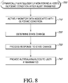
- a method of transitioning between states associated with a host's glycemic condition comprising: evaluating sensor data from a continuous glucose sensor and activating an alert state based on the sensor data meeting one or more active transition criteria associated with a hypoglycemic condition or hyperglycemic condition; providing an output associated with the active alert state, wherein the output is indicative of the hypoglycemic condition or hyperglycemic condition; transitioning from the active state to an acknowledged state for a time period responsive to at least one of a user acknowledgment of the alert state or data indicative of the host's glucose trending toward euglycemia; actively monitoring data associated with the host's hypoglycemic or hyperglycemic condition for a time period in the acknowledged state; and transitioning from the acknowledged state to at least one of an inactive state or active state responsive to the data associated with the host's hypoglycemic or hyperglycemic condition meeting one or more predetermined criteria.
- the transitioning from the active state to an acknowledged state comprises transitioning from the active state to the acknowledged state based on the data indicative of the host's glucose trending toward euglycemia, wherein the data is selected from the group consisting of a) sensor data indicative of a change in glucose trend or b) insulin information associated with a correction of the condition.
- the transitioning from the active state to an acknowledged state comprises transitioning from the active state to the acknowledged state based on the a user acknowledgment, wherein the data is selected from the group consisting of a) a user acknowledgement of the alert on a user interface or b) user input insulin information or c) user input of meal information.
- the actively monitoring comprises monitoring at least one of the sensor data, sensor diagnostic information, meal information, insulin information, or event information.
- transitioning from the acknowledged state comprises transitioning from the acknowledged state to the inactive state based on the sensor data no longer meeting the one or more criteria associated with a hypoglycemic condition or hyperglycemic condition.
- transitioning from the acknowledged state comprises transitioning from the acknowledged state to the inactive state based on the sensor data meeting one or more inactive transition criteria, wherein the inactivation criteria are different from the one or more active transition criteria associated with a hypoglycemic condition or hyperglycemic condition.
- transitioning from the acknowledged state comprises transitioning from the acknowledged state to the inactive state based on insulin data and/or meal information.
- transitioning from the acknowledged state comprises transitioning from the acknowledged state to the active state based on the one or more active transition criteria associated with a hypoglycemic condition or hyperglycemic condition being met and based on an expiration of a predetermined time period.
- after receiving the user acknowledgement of the alert state and determining data is indicative of the host's glucose trending toward euglycemia, further comprising transitioning from the acknowledged state to the active state based on the host's glucose trending away from euglycemia during the active monitoring time period.
- the method further comprises selectively outputting information associated with the state transition.
- the output associated with a transition to the active state is different from the output association with a transition from the acknowledged state to the inactive state.
- a system for processing data comprising: a continuous analyte sensor configured to be implanted within a body; and sensor electronics configured to receive and process sensor data output by the sensor, the sensor electronics including a processor configured to: evaluate sensor data from a continuous glucose sensor and activating an alert state based on the sensor data meeting one or more active transition criteria associated with a hypoglycemic condition or hyperglycemic condition; provide an output associated with the active alert state, wherein the output is indicative of the hypoglycemic condition or hyperglycemic condition; transition from the active state to an acknowledged state for a time period responsive to at least one of a user acknowledgment of the alert state or data indicative of the host's glucose trending toward euglycemia; actively monitor data associated with the host's hypoglycemic or hyperglycemic condition for a time period in the acknowledged state; and transition from the acknowledged state to at least one of an inactive state or active state responsive to the data associated with the host'
- the transitioning from the active state to an acknowledged state comprises transitioning from the active state to the acknowledged state based on the data indicative of the host's glucose trending toward euglycemia, wherein the data is selected from the group consisting of a) sensor data indicative of a change in glucose trend or b) insulin information associated with a correction of the condition.
- transitioning from the active state to an acknowledged state comprises transitioning from the active state to the acknowledged state based on the a user acknowledgment, wherein the data is selected from the group consisting of a) a user acknowledgement of the alert on a user interface or b) user input insulin information or c) user input of meal information.
- the actively monitoring comprises monitoring at least one of the sensor data, sensor diagnostic information, meal information, insulin information, or event information.
- transitioning from the acknowledged state comprises transitioning from the acknowledged state to the inactive state based on the sensor data no longer meeting the one or more criteria associated with a hypoglycemic condition or hyperglycemic condition.
- transitioning from the acknowledged state comprises transitioning from the acknowledged state to the inactive state based on the sensor data meeting one or more inactive transition criteria, wherein the inactivation criteria are different from the one or more active transition criteria associated with a hypoglycemic condition or hyperglycemic condition.
- transitioning from the acknowledged state comprises transitioning from the acknowledged state to the inactive state based on insulin data and/or meal information.
- transitioning from the acknowledged state comprises transitioning from the acknowledged state to the active state based on the one or more active transition criteria associated with a hypoglycemic condition or hyperglycemic condition being met and based on an expiration of a predetermined time period.
- after receiving the user acknowledgement of the alert state and determining data is indicative of the host's glucose trending toward euglycemia, further comprising transitioning from the acknowledged state to the active state based on the host's glucose trending away from euglycemia during the active monitoring time period.
- the system further comprises selectively outputting information associated with the state transition.
- the output associated with a transition to the active state is different from the output association with a transition from the acknowledged state to the inactive state.
- a method of determining when to re-alert a user based after a user has acknowledged a first alert comprising: initially activating an alert state based on one or more criteria based on data associated with a hypoglycemic or hyperglycemic condition being met; transitioning to an acknowledged state for an predetermined active monitoring time period responsive to at least one of a user acknowledgment or data indicative of the host's glucose trending toward euglycemia; actively monitoring, by a processor module, data associated with the host's hypoglycemic or hyperglycemic condition during the active monitoring time period; and reactivating the first alert state during the acknowledgement time period initiated by the data associated with the host's hypoglycemic or hyperglycemic condition meeting one or more second criteria.
- the second one or more criteria are different from the first one or more criteria.
- the method further comprises providing a first output associated with the initially activating and providing a second output associated with the reactivating.
- the first output and the second output are different.
- the second criteria comprise conditions indicative of the host's glucose trending toward euglycemia and further comprise conditions indicative of the host's glucose trending away from euglycemia after trending toward euglycemia during the active monitoring time period.
- the one or more second criteria associated with reactivation comprise a change in a real-time glucose value as compared to the real-time glucose value associated with the initially activating.
- a system for processing data comprising: a continuous analyte sensor configured to be implanted within a body; and sensor electronics configured to receive and process sensor data output by the sensor, the sensor electronics including a processor configured to: initially activate an alert state based on one or more criteria based on data associated with a hypoglycemic or hyperglycemic condition being met; transition to an acknowledged state for an predetermined active monitoring time period responsive to at least one of a user acknowledgment or data indicative of the host's glucose trending toward euglycemia; actively monitor data associated with the host's hypoglycemic or hyperglycemic condition during the active monitoring time period; and reactivate the first alert state during the acknowledgement time period initiated by the data associated with the host's hypoglycemic or hyperglycemic condition meeting one or more second criteria.
- the second one or more criteria are different from the first one or more criteria.
- the system further comprises providing a first output associated with the initially activating and providing a second output associated with the reactivating.
- the first output and the second output are different.
- the second criteria comprise conditions indicative of the host's glucose trending toward euglycemia and further comprise conditions indicative of the host's glucose trending away from euglycemia after trending toward euglycemia during the active monitoring time period.
- the one or more second criteria associated with reactivation comprise a change in a real-time glucose value as compared to the real-time glucose value associated with the initially activating.
- a method of avoiding unnecessary hyperglycemic alerts comprising: initially activating a first alert state based on one or more first criteria associated with a hyperglycemic condition; waiting a time period before providing an output associated with the first alert state; actively monitoring, by a processor module, data associated with the host's hyperglycemic condition during the waiting time period; and providing an output associated with the first alert state after the waiting time period based on the data associated with the host's hyperglycemic condition meeting one or more second criteria.
- the actively monitoring comprises determining an average glucose over a window of time.
- the actively monitoring comprises determining an amplitude and/or direction of rate of change. In an example of the seventh aspect, the actively monitoring comprises determining an amplitude and/or direction of rate of acceleration. In an example of the seventh aspect, the actively monitoring comprises evaluating insulin information. In an example of the seventh aspect, the actively monitoring comprises evaluating meal information or timing. In an example of the seventh aspect, the waiting time period is user selectable. In an example of the seventh aspect, the method further comprises not providing output associated with the first alert state after the waiting time period based on the data associated with the host's hyperglycemic condition not meeting the one or more second criteria. In an example of the seventh aspect, the one or more first criteria and the one or more second criteria are the same.
- the one or more first criteria and the one or more second criteria are different.
- the method further comprises transitioning from the first alert state to an inactive alert state based on the data associated with the host's hyperglycemic condition meeting one or more third criteria.
- the one or more first criteria and the one or more third criteria are the same.
- the one or more first criteria and the one or more third criteria are different.
- a system for processing data comprising: a continuous analyte sensor configured to be implanted within a body; and sensor electronics configured to receive and process sensor data output by the sensor, the sensor electronics including a processor configured to: initially activate a first alert state based on one or more first criteria associated with a hyperglycemic condition; wait a time period before providing an output associated with the first alert state; actively monitor data associated with the host's hyperglycemic condition during the waiting time period; and provide an output associated with the first alert state after the waiting time period based on the data associated with the host's hyperglycemic condition meeting one or more second criteria.
- the actively monitoring comprises determining an average glucose over a window of time. In an example of the eighth aspect, the actively monitoring comprises determining an amplitude and/or direction of rate of change. In an example of the eighth aspect, the actively monitoring comprises determining an amplitude and/or direction of rate of acceleration. In an exampleof the eighth aspect, the actively monitoring comprises evaluating insulin information. In an example of the eighth aspect, the actively monitoring comprises evaluating meal information or timing. In an example of the eighth aspect, the waiting time period is user selectable. In an example of the eighth aspect, the system further comprises not providing output associated with the first alert state after the waiting time period based on the data associated with the host's hyperglycemic condition not meeting the one or more second criteria.
- the one or more first criteria and the one or more second criteria are the same. In an example of the eighth aspect, the one or more first criteria and the one or more second criteria are different. In an example of the eighth aspect, the system further comprises transitioning from the first alert state to an inactive alert state based on the data associated with the host's hyperglycemic condition meeting one or more third criteria. In an example of the eighth aspect, the one or more first criteria and the one or more third criteria are the same. In an example of the eighth aspect, the one or more first criteria and the one or more third criteria are different.
- Any aspect or embodiment of a method can be performed by a system or apparatus of another aspect or embodiment, and any aspect or embodiment of a system can be configured to perform a method of another aspect or embodiment.
- FIG. 1 depicts an example system 100, in accordance with some example implementations.
- the system 100 includes a continuous analyte sensor system 8 including sensor electronics 12 and a continuous analyte sensor 10.
- the system 100 may include other devices and/or sensors, such as medicament delivery pump 2 and glucose meter 4.
- the continuous analyte sensor 10 may be physically connected to sensor electronics 12 and may be integral with (e.g., non-releasably attached to) or releasably attachable to the continuous analyte sensor 10.
- the sensor electronics 12, medicament delivery pump 2, and/or glucose meter 4 may couple with one or more devices, such as display devices 14, 16, 18, and/or 20.
- the system 100 may include a cloud- based analyte processor 490 configured to analyze analyte data (and/or other patient related data) provided via network 406 (e.g., via wired, wireless, or a combination thereof) from sensor system 8 and other devices, such as display devices 14-20 and the like, associated with the host (also referred to as a patient) and generate reports providing high-level information, such as statistics, regarding the measured analyte over a certain time frame.
- a cloud-based analyte processing system may be found in U.S. Patent Application No. 61/655,991 , entitled “Cloud-Based Processing of Analyte Data” and filed on June 5, 2012.
- the sensor electronics 12 may include electronic circuitry associated with measuring and processing data generated by the continuous analyte sensor 10. This generated continuous analyte sensor data may also include algorithms, which can be used to process and calibrate the continuous analyte sensor data, although these algorithms may be provided in other ways as well.
- the sensor electronics 12 may include hardware, firmware, software, or a combination thereof to provide measurement of levels of the analyte via a continuous analyte sensor, such as a continuous glucose sensor. An example implementation of the sensor electronics 12 is described further below with respect to Figure 2 .
- sensor data is a broad term and is to be given its ordinary and customary meaning to a person of ordinary skill in the art (and is not to be limited to a special or customized meaning), and furthermore refers without limitation to any data associated with a sensor, such as a continuous analyte sensor.
- Sensor data includes a raw data stream, or simply a data stream, of analog or digital signal related to a measured analyte from an analyte sensor (or other signal received from another sensor), as well as calibrated and/or filtered raw data.
- the sensor data comprises digital data in "counts" converted by an A/D converter from an analog signal (e.g., voltage or amps) and includes one or more data points representative of a glucose concentration.
- sensor data point and “data point” refer generally to a digital representation of sensor data at a particular time.
- the term broadly encompasses a plurality of time spaced data points from a sensor, such as from a substantially continuous glucose sensor, which includes individual measurements taken at time intervals ranging from fractions of a second up to, e.g., 1, 2, or 5 minutes or longer.
- the sensor data includes an integrated digital value representative of one or more data points averaged over a time period.
- sensor data may include calibrated data, smoothed data, filtered data, transformed data, and/or any other data associated with a sensor.
- the sensor electronics 12 may, as noted, couple (e.g., wirelessly and the like) with one or more devices, such as display devices 14, 16, 18, and/or 20.
- the display devices 14, 16, 18, and/or 20 may be configured for presenting information (and/or alarming), such as sensor information transmitted by the sensor electronics 12 for display at the display devices 14, 16, 18, and/or 20.
- the display devices may include a relatively small, key fob-like display device 14, a relatively large, hand-held display device 16, a cellular phone 18 (e.g., a smart phone, a tablet, and the like), a computer 20, and/or any other user equipment configured to at least present information (e.g., medicament delivery information, discrete self-monitoring glucose readings, heart rate monitor, caloric intake monitor, and the like).
- a relatively small, key fob-like display device 14 e.g., a relatively large, hand-held display device 16
- a cellular phone 18 e.g., a smart phone, a tablet, and the like
- computer 20 e.g., a computer 20, and/or any other user equipment configured to at least present information (e.g., medicament delivery information, discrete self-monitoring glucose readings, heart rate monitor, caloric intake monitor, and the like).
- the relatively small, key fob-like display device 14 may comprise a wrist watch, a belt, a necklace, a pendent, a piece of jewelry, an adhesive patch, a pager, a key fob, a plastic card (e.g., credit card), an identification (ID) card, and/or the like.
- This small display device 14 may include a relatively small display (e.g., smaller than the large display device 16) and may be configured to display certain types of displayable sensor information, such as a numerical value and an arrow.
- the relatively large, hand-held display device 16 may comprise a hand-held receiver device, a palm-top computer, and/or the like.
- This large display device may include a relatively larger display (e.g., larger than the small display device 14) and may be configured to display information, such as a graphical representation of the continuous sensor data including current and historic sensor data output by sensor system 8.
- the continuous analyte sensor 10 comprises a sensor for detecting and/or measuring analytes, and the continuous analyte sensor 10 may be configured to continuously detect and/or measure analytes as a non-invasive device, a subcutaneous device, a transdermal device, and/or an intravascular device. In some example implementations, the continuous analyte sensor 10 may analyze a plurality of intermittent blood samples, although other analytes may be used as well.
- the continuous analyte sensor 10 may comprise a glucose sensor configured to measure glucose in the blood using one or more measurement techniques, such as enzymatic, chemical, physical, electrochemical, spectrophotometric, polarimetric, calorimetric, iontophoretic, radiometric, immunochemical, and the like.
- the glucose sensor may be comprise any device capable of measuring the concentration of glucose and may use a variety of techniques to measure glucose including invasive, minimally invasive, and non-invasive sensing techniques (e.g., fluorescence monitoring), to provide a data, such as a data stream, indicative of the concentration of glucose in a host.
- the data stream may be raw data signal, which is converted into a calibrated and/or filtered data stream used to provide a value of glucose to a host, such as a user, a patient, or a caretaker (e.g., a parent, a relative, a guardian, a teacher, a doctor, a nurse, or any other individual that has an interest in the wellbeing of the host).
- a host such as a user, a patient, or a caretaker (e.g., a parent, a relative, a guardian, a teacher, a doctor, a nurse, or any other individual that has an interest in the wellbeing of the host).
- the continuous analyte sensor 10 may be implanted as at least one of the following types of sensors: an implantable glucose sensor, a transcutaneous glucose sensor, implanted in a host vessel or extracorporeally, a subcutaneous sensor, a refillable subcutaneous sensor, an intravascular sensor.
- the disclosure herein refers to some implementations that include a continuous analyte sensor 10 comprising a glucose sensor
- the continuous analyte sensor 10 may comprises other types of analyte sensors as well.
- the glucose sensor as an implantable glucose sensor
- other types of devices capable of detecting a concentration of glucose and providing an output signal representative of glucose concentration may be used as well.
- glucose as the analyte being measured, processed, and the like
- other analytes may be used as well including, for example, ketone bodies (e.g., acetone, acetoacetic acid and beta hydroxybutyric acid, lactate, etc.), glucagon, Acetyl Co A, triglycerides, fatty acids, intermediaries in the citric acid cycle, choline, insulin, cortisol, testosterone, and the like.
- the sensor electronics 12 may include sensor electronics that are configured to process sensor information, such as sensor data, and generate transformed sensor data and displayable sensor information, e.g., via a processor module.
- the processor module may transform sensor data into one or more of the following: filtered sensor data (e.g., one or more filtered analyte concentration values), raw sensor data, calibrated sensor data (e.g., one or more calibrated analyte concentration values), rate of change information, trend information, rate of acceleration/deceleration information, sensor diagnostic information, location information, alarm/alert information, calibration information, smoothing and/or filtering algorithms of sensor data, and/or the like.
- filtered sensor data e.g., one or more filtered analyte concentration values
- calibrated sensor data e.g., one or more calibrated analyte concentration values
- rate of change information e.g., trend information, rate of acceleration/deceleration information, sensor diagnostic information, location information, alarm/alert information, calibration information,
- a processor module 214 is configured to achieve a substantial portion, if not all, of the data processing.
- Processor module 214 may be integral to sensor electronics 12 and/or may be located remotely, such as in one or more of devices 14, 16, 18, and/or 20 and/or cloud 490.
- processor module 214 may comprise a plurality of smaller subcomponents or submodules.
- processor module 214 may include an alert module (not shown) or prediction module (not shown), or any other suitable module that may be utilized to efficiently process data.
- processor module 214 When processor module 214 is made up of a plurality of submodules, the submodules may be located within processor module 214, including within the sensor electronic 12 or other associated devices (e.g., 14, 16, 18, 20 and/or 490). For example, in some embodiments, processor module 214 may be located at least partially within cloud-based analyte processor 490 or elsewhere in network 406.
- the processor module 214 may be configured to calibrate the sensor data, and the data storage memory 220 may store the calibrated sensor data points as transformed sensor data. Moreover, the processor module 214 may be configured, in some example implementations, to wirelessly receive calibration information from a display device, such as devices 14, 16, 18, and/or 20, to enable calibration of the sensor data from sensor 12. Furthermore, the processor module 214 may be configured to perform additional algorithmic processing on the sensor data (e.g., calibrated and/or filtered data and/or other sensor information), and the data storage memory 220 may be configured to store the transformed sensor data and/or sensor diagnostic information associated with the algorithms.
- a display device such as devices 14, 16, 18, and/or 20
- the processor module 214 may be configured to perform additional algorithmic processing on the sensor data (e.g., calibrated and/or filtered data and/or other sensor information)
- the data storage memory 220 may be configured to store the transformed sensor data and/or sensor diagnostic information associated with the algorithms.
- the sensor electronics 12 may comprise an application-specific integrated circuit (ASIC) 205 coupled to a user interface 222.
- the ASIC 205 may further include a potentiostat 210, a telemetry module 232 for transmitting data from the sensor electronics 12 to one or more devices, such devices 14, 16, 18, and/or 20, and/or other components for signal processing and data storage (e.g., processor module 214 and data storage memory 220).
- Figure 2 depicts ASIC 205, other types of circuitry may be used as well, including field programmable gate arrays (FPGA), one or more microprocessors configured to provide some (if not all of) the processing performed by the sensor electronics 12, analog circuitry, digital circuitry, or a combination thereof.
- FPGA field programmable gate arrays
- the potentiostat 210 is coupled to a continuous analyte sensor 10, such as a glucose sensor to generate sensor data from the analyte.
- the potentiostat 210 may also provide via data line 212 a voltage to the continuous analyte sensor 10 to bias the sensor for measurement of a value (e.g., a current and the like) indicative of the analyte concentration in a host (also referred to as the analog portion of the sensor).
- the potentiostat 210 may have one or more channels depending on the number of working electrodes at the continuous analyte sensor 10.
- the potentiostat 210 may include a resistor that translates a current value from the sensor 10 into a voltage value, while in some example implementations, a current-to-frequency converter (not shown) may also be configured to integrate continuously a measured current value from the sensor 10 using, for example, a charge-counting device. In some example implementations, an analog-to-digital converter (not shown) may digitize the analog signal from the sensor 10 into so-called "counts" to allow processing by the processor module 214. The resulting counts may be directly related to the current measured by the potentiostat 210, which may be directly related to an analyte level, such as a glucose level, in the host.
- an analyte level such as a glucose level
- the telemetry module 232 may be operably connected to processor module 214 and may provide the hardware, firmware, and/or software that enable wireless communication between the sensor electronics 12 and one or more other devices, such as display devices, processors, network access devices, and the like.
- wireless radio technologies that can be implemented in the telemetry module 232 include Bluetooth, Bluetooth Low-Energy, ANT, ANT+, ZigBee, IEEE 802.11, IEEE 802.16, cellular radio access technologies, radio frequency (RF), infrared (IR), paging network communication, magnetic induction, satellite data communication, spread spectrum communication, frequency hopping communication, near field communications, and/or the like.
- the telemetry module 232 comprises a Bluetooth chip, although the Bluetooth technology may also be implemented in a combination of the telemetry module 232 and the processor module 214.
- the processor module 214 may control the processing performed by the sensor electronics 12.
- the processor module 214 may be configured to process data (e.g., counts), from the sensor, filter the data, calibrate the data, perform fail-safe checking, and/or the like.
- the processor module 214 may comprise a digital filter, such as for example an infinite impulse response (IIR) or a finite impulse response (FIR) filter.
- This digital filter may smooth a raw data stream received from sensor 10.
- digital filters are programmed to filter data sampled at a predetermined time interval (also referred to as a sample rate).
- time interval also referred to as a sample rate.
- the potentiostat 210 may be configured to measure continuously the analyte, for example, using a current-to-frequency converter.
- the processor module 214 may be programmed to request, at predetermined time intervals (acquisition time), digital values from the integrator of the current-to-frequency converter. These digital values obtained by the processor module 214 from the integrator may be averaged over the acquisition time due to the continuity of the current measurement. As such, the acquisition time may be determined by the sampling rate of the digital filter.
- the processor module 214 may further include a data generator (not shown) configured to generate data packages for transmission to devices, such as the display devices 14, 16, 18, and/or 20. Furthermore, the processor module 214 may generate data packets for transmission to these outside sources via telemetry module 232.
- the data packages may, as noted, be customizable for each display device, and/or may include any available data, such as a time stamp, displayable sensor information, transformed sensor data, an identifier code for the sensor and/or sensor electronics 12, raw data, filtered data, calibrated data, rate of change information, trend information, error detection or correction, and/or the like.
- the processor module 214 may also include a program memory 216 and other memory 218.
- the processor module 214 may be coupled to a communications interface, such as a communication port 238, and a source of power, such as a battery 234.
- the battery 234 may be further coupled to a battery charger and/or regulator 236 to provide power to sensor electronics 12 and/or charge the battery 234.
- the program memory 216 may be implemented as a semi-static memory for storing data, such as an identifier for a coupled sensor 10 (e.g., a sensor identifier (ID)) and for storing code (also referred to as program code) to configure the ASIC 205 to perform one or more of the operations/functions described herein.
- the program code may configure processor module 214 to process data streams or counts, filter, calibrate, perform fail-safe checking, and the like.
- the memory 218 may also be used to store information.
- the processor module 214 including memory 218 may be used as the system's cache memory, where temporary storage is provided for recent sensor data received from the sensor.
- the memory may comprise memory storage components, such as read-only memory (ROM), random-access memory (RAM), dynamic-RAM, static-RAM, non-static RAM, easily erasable programmable read only memory (EEPROM), rewritable ROMs, flash memory, and the like.
- the data storage memory 220 may be coupled to the processor module 214 and may be configured to store a variety of sensor information.
- the data storage memory 220 stores one or more days of continuous analyte sensor data.
- the data storage memory may store 1, 2, 3, 4, 5, 6, 7, 8, 9, 10, 11, 12, 13, 14, 15, 20, and/or 30 (or more days) of continuous analyte sensor data received from sensor 10.
- the stored sensor information may include one or more of the following: a time stamp, raw sensor data (one or more raw analyte concentration values), calibrated data, filtered data, transformed sensor data, and/or any other displayable sensor information, calibration information (e.g., reference BG values and/or prior calibration information), sensor diagnostic information, and the like.
- the user interface 222 may include a variety of interfaces, such as one or more buttons 224, a liquid crystal display (LCD) 226, a vibrator 228, an audio transducer (e.g., speaker) 230, a backlight (not shown), and/or the like.
- the components that comprise the user interface 222 may provide controls to interact with the user (e.g., the host).
- One or more buttons 224 may allow, for example, toggle, menu selection, option selection, status selection, yes/no response to on-screen questions, a "turn off' function (e.g., for an alarm), an "acknowledged" function (e.g., for an alarm), a reset, and/or the like.
- the LCD 226 may provide the user with, for example, visual data output.
- the audio transducer 230 may provide audible signals in response to triggering of certain alerts, such as present and/or predicted hyperglycemic and hypoglycemic conditions.
- audible signals may be differentiated by tone, volume, duty cycle, pattern, duration, and/or the like.
- the audible signal may be configured to be silenced (e.g., acknowledged or turned off) by pressing one or more buttons 224 on the sensor electronics 12 and/or by signaling the sensor electronics 12 using a button or selection on a display device (e.g., key fob, cell phone, and/or the like).
- a tactile alarm including a poking mechanism configured to "poke" or physically contact the patient in response to one or more alarm conditions.
- the battery 234 may be operatively connected to the processor module 214 (and possibly other components of the sensor electronics 12) and provide the necessary power for the sensor electronics 12.
- the battery is a Lithium Manganese Dioxide battery, however any appropriately sized and powered battery can be used (e.g., AAA, Nickel-cadmium, Zinc-carbon, Alkaline, Lithium, Nickel-metal hydride, Lithium-ion, Zinc-air, Zinc-mercury oxide, Silver-zinc, or hermetically-sealed).
- the battery is rechargeable.
- a plurality of batteries can be used to power the system.
- the receiver can be transcutaneously powered via an inductive coupling, for example.
- a battery charger and/or regulator 236 may be configured to receive energy from an internal and/or external charger.
- a battery regulator (or balancer) 236 regulates the recharging process by bleeding off excess charge current to allow all cells or batteries in the sensor electronics 12 to be fully charged without overcharging other cells or batteries.
- the battery 234 (or batteries) is configured to be charged via an inductive and/or wireless charging pad, although any other charging and/or power mechanism may be used as well.
- One or more communication ports 238, also referred to as external connector(s), may be provided to allow communication with other devices, for example a PC communication (com) port can be provided to enable communication with systems that are separate from, or integral with, the sensor electronics 12.
- the communication port for example, may comprise a serial (e.g., universal serial bus or "USB") communication port, and allow for communicating with another computer system (e.g., PC, personal digital assistant or "PDA," server, or the like).
- the sensor electronics 12 is able to transmit historical data to a PC or other computing device (e.g., an analyte processor as disclosed herein) for retrospective analysis by a patient and/or physician.
- an on-skin portion of the sensor electronics may be simplified to minimize complexity and/or size of on-skin electronics, for example, providing only raw, calibrated, and/or filtered data to a display device configured to run calibration and other algorithms required for displaying the sensor data.
- the sensor electronics 12 may be implemented to execute prospective algorithms used to generate transformed sensor data and/or displayable sensor information, including, for example, algorithms that: evaluate a clinical acceptability of reference and/or sensor data, evaluate calibration data for best calibration based on inclusion criteria, evaluate a quality of the calibration, compare estimated analyte values with time corresponding measured analyte values, analyze a variation of estimated analyte values, evaluate a stability of the sensor and/or sensor data, detect signal artifacts (noise), replace signal artifacts, determine a rate of change and/or trend of the sensor data, perform dynamic and intelligent analyte value estimation, perform diagnostics on the sensor and/or sensor data, set modes of operation, evaluate the data for aberrancies, and/or the like.
- algorithms that: evaluate a clinical acceptability of reference and/or sensor data, evaluate calibration data for best calibration based on inclusion criteria, evaluate a quality of the calibration, compare estimated analyte values with time corresponding measured analyte values, analyze a variation of estimated
- FIG. 2 Although separate data storage and program memories are shown in Figure 2 , a variety of configurations may be used as well. For example, one or more memories may be used to provide storage space to support data processing and storage requirements at sensor electronics 12.
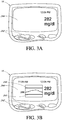
- Hand-held receiver 16 may comprise systems necessary to receive, process, and display sensor data from an analyte sensor, such as described elsewhere herein.
- the hand-held receiver 16 can be a pager-sized device, for example, and comprise a user interface that has a plurality of buttons 242 and a liquid crystal display (LCD) screen 244, and which can include a backlight.
- the user interface can also include a keyboard, a speaker, and a vibrator.
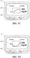
- a user is able to toggle through some or all of the screens shown in Figures 3A to 3D using a toggle button on the hand-held receiver.
- the user is able to interactively select the type of output displayed on their user interface.
- the sensor output can have alternative configurations.
- analyte values are displayed on e.g., a display of medical device received.
- prompts or messages can be displayed on the display device to convey information to the user, such as reference outlier values, requests for reference analyte values, therapy recommendations, deviation of the measured analyte values from the estimated analyte values, providing predictive alert/alarm, monitoring the glycemic alert state after the alert/alarm is triggered, determining state changes, or the like.
- prompts can be displayed to guide the user through calibration or troubleshooting of the calibration.
- Figures 4A to 4C illustrate some additional visual displays that can be provided on the user interface 222. While these visual displays may include the same or similar output to the ones shown on hand-held device 16 in Figure 3 , and the visual displays of Figure 4 can be provided on any suitable user interface 222, such as those on devices 14, 16, 18, 20.
- the LCD 226 is a touch-activated screen, enabling each selection by a user, for example, from a menu on the screen. Buttons can provide for toggle, menu selection, option selection, mode selection, and reset, for example.
- a microphone can be provided to allow for voice-activated control.
- Figure 4A is an illustration of an LCD screen 226 showing continuous and single point glucose information in the form of a trend graph 184 and a single numerical value 186.
- the trend graph shows upper and lower boundaries 182 representing a target range between which the host should maintain his/her glucose values.
- the receiver is configured such that these boundaries 182 can be configured or customized by a user, such as the host or a care provider.
- visual boundaries 182 in combination with continuous analyte values over time (e.g., a trend graph 184), a user can better learn how to control his/her analyte concentration (e.g., a person with diabetes can better learn how to control his/her glucose concentration) as compared to single point (e.g., single numerical value 186) alone.
- Figure 4A illustrates a 1-hour trend graph (e.g., depicted with a time range 188 of 1-hour), a variety of time ranges can be represented on the screen 226, for example, 3-hour, 9-hour, 1-day, and the like.
- FIG. 4B is an illustration of an LCD screen 226 showing a low alert screen that can be displayed responsive to a host's analyte concentration falling below a lower boundary (see boundaries 182).
- a host's glucose concentration has fallen to 55 mg/dL, which is below the lower boundary set in FIG. 4A , for example.
- the arrow 190 represents the direction of the analyte trend, for example, indicating that the glucose concentration is continuing to drop.
- the annotation 192 (“LOW") is helpful in immediately and clearly alerting the host that his/her glucose concentration has dropped below a preset limit, and what may be considered to be a clinically safe value, for example.
- FIG 4C is an illustration of an LCD screen 226 showing a high alert screen that can be displayed responsive to a host's analyte concentration rising above an upper boundary (see boundaries 182).
- a host's glucose concentration has risen to 200 mg/dL, which is above a boundary set by the host, thereby triggering the high alert screen.
- the arrow 190 represents the direction of the analyte trend, for example, indicating that the glucose concentration is continuing to rise.
- the annotation 192 (“HIGH") is helpful in immediately and clearly alerting the host that his/her glucose concentration has above a preset limit, and what may be considered to be a clinically safe value, for example.
- screens can be provided for illustrating any of the information described in the provided embodiments, as well as additional information.
- a user can toggle between these screens and/or the screens can be automatically displayed responsive to programming within the e.g., hand-held receiver 16, and can be simultaneously accompanied by another type of alert (e.g., audible or tactile).
- Figure 4D is a screenshot of a smartphone 18 display illustrating one embodiment of an alert indicting that the user's blood glucose is dropping and will soon be in a low range.
- Figure 4E is a screenshot of a smartphone 18 display illustrating one embodiment of a blood glucose trend graph.
- Figure 4F is an embodiment of a blood glucose trend arrow.
- the processor module 214 may provide a predictive alert on a smartphone 18 display or user interface 222 when a severe hypoglycemic event is predicted to occur in the near future.
- the predictive alert may be shown when a severe hypoglycemic event is predicted to occur within 5 minutes, 10 minutes, 15 minutes, 20 minutes, 30 minutes, etc.
- an arrow 300 may be displayed on a trend screen pointing towards a BG value 302 that indicates a severe hypoglycemic event, such as 55 mg/dL.
- the arrow 300 may change color as it transitions from euglycemia to hypoglycemia, to emphasize the change in glucose levels that is expected.
- the arrow 300 may be animated to flash to emphasize the seriousness of the alert.
- the display may also show text 304, such as Going LOW.
- This predictive alert may be configured to be prioritized over (override) whatever mode or application the smartphone 18 is in at the time the processor module 214 determines that a severe hypoglycemic event is predicted to occur. In other words, the alert may interrupt whatever is currently on the smartphone's user interface 222.
- the processor module 214 may be programmed with a blood glucose value corresponding to a threshold below which the user is considered to be hypoglycemic. As the processor module 214 receives as inputs multiple EGV's at time-spaced intervals, it processes the inputs by comparing each one to the programmed value, and also to previously received EGV's. If the user's blood glucose shows a downward trend, and is approaching the programmed value, the processor module 214 outputs an alert such as the one shown in Figure 4D to the smartphone's user interface 222. The user thus receives an advance warning of a potential hypoglycemic event, so that he or she can take appropriate action to avoid the hypoglycemic event.
- the processor module 214 may change the color of the user interface 222 to reflect the user's current blood glucose level.
- the user's EGV may be displayed on the screen as a number, as a trend graph, a horizontal bar graph, etc.
- the text and/or background on the user interface 222 may change when the user's current blood glucose level transitions from one state to another.
- the text/background may show a first color, such as green, if the user's blood glucose is within a healthy range, and a second color, such as red, if the user's blood glucose is low or high.
- a first color may be used for the healthy range, a second color for low, and a third color for high.
- the intensity of the color may increase.
- the text/background may also flash, with the frequency of the flashing increasing as the user's blood glucose becomes increasingly lower or higher.
- the processor module 214 may be programmed with blood glucose values corresponding to low and high threshold BG values. As the processor module 214 receives as inputs multiple EGV's at time-spaced intervals, it processes the inputs by comparing each one to the programmed values. If the user's blood glucose value crosses one of the thresholds, the processor module 214 outputs an alert to the smartphone's user interface 222 in the form of changing the color of the text and/or background. If the user's blood glucose value continues to become increasingly low or high, the processor module 214 produces additional outputs, such as increasing the intensity of the color and/or causing the text/background to flash. These additional outputs may be generated in response to the processor module 214 comparing input EGV's to additional programmed threshold values.
- the processor module 214 may use iconography and/or alert symbols that reflect real time data. For example, the user's blood glucose becomes low, an icon on the smartphone 18 may show an image of the user's BG trend graph using e.g., actual data points from EGV's.
- the input-processing-output for this embodiment would be substantially the same as that for the previous embodiment.
- the processor module 214 may go into an emergency response instruction mode.
- This mode may include an alarm to alert others in close proximity to the user that something is wrong.
- step-by-step instructions on how to assist the unconscious user may be shown on the smartphone's user interface 222, such as administering glucose tabs or another form of carbohydrates, calling an ambulance, etc.
- the processor module 214 may receive an input from a CGM, which is the user's EGV.
- the processor module 214 may process the input by comparing it to one or more threshold values, and determine that the user's blood glucose is low.
- the processor module 214 may produce an output in the form of an alert. If the user does not respond to the alert by pressing a button or an area on a touchscreen user interface 222, for example, the processor module 214 may determine that the user may be unconscious, and produces another output in the form of the emergency response instruction mode described herein.
- the processor module 214 may provide differentiated visual high/low thresholds versus alert thresholds.
- the processor module 214 may be programmed with low and high blood glucose thresholds. These thresholds may be shown on a blood glucose trend graph on the user interface 222 as horizontal lines that the user should strive not to cross. Ordinarily, crossing either of the lines might generate an alert. However, excessive alerts can be annoying to the user, and can decrease patient compliance.
- the visual high/low target range boundaries shown on the graph may be different from boundaries that generate an alert. For example, the boundaries that generate an alert might be wider than the visual target range threshold boundaries on the user interface 222, and the boundaries that generate an alert may be hidden from view.
- This configuration gives the user a little bit of a buffer zone to cross either of the visual boundaries without generating an alert.
- the boundaries that generate an alert might be visible, but distinguishable from the target range boundaries. Examples of visual distinctions include different colors, flashing vs. static, solid vs. dashed, different line weights, an alarm icon adjacent the alarm lines, etc.
- the high/low target boundaries may always be displayed, but the alert boundaries may be shown or not based on a user setting, a mode (e.g. silent), thresholds, etc.
- a user interface of the processor module 214 may be the first thing that the user sees when he or she activates the smartphone's user interface 222. For example, many smartphones 18 automatically put the user interface 222 to sleep (e.g., in a sleep mode) when no activity is detected for a predetermined amount of time. This measure saves battery power. To reactivate the user interface 222, the user must press a button on the smartphone 18. In certain embodiments, when the user reactivates the user interface 222, the first thing he or she sees is the user interface of the processor module 214.
- the processor module 214 receives as an input a notification that the user interface 222 has entered sleep mode, followed by a later notification that the user interface 222 has been reactivated.
- the processor module 214 may process these inputs and produce as an output a display of the user interface 222 of the processor module 214 on the smartphone 18.
- a trend graph displayed by the processor module 214 is color coded.
- the color of the graph 400 (either the trend line 402 or the background 404) may be green if within a target range, yellow if ⁇ 10% outside the target range, orange if ⁇ 15% outside the target range, and red if ⁇ 20% outside the target range.
- a trend arrow 406 may be similarly color coded, and the angle at which the trend arrow 406 is oriented may correspond to the actual rate of change of the user's glucose, e.g. a more horizontal arrow indicates a low rate of change, while a steeply sloping arrow indicates a high rate of change.
- the processor module 214 may receive as inputs continuous EGV's from a sensor system 8.
- the rate of change is calculated by the sensor system 8 and sent to the processor module 214 for display (e.g., determination of how to display and resulting display), although the processor module 214 may also perform rate of change calculations.
- the rate of change based on a linear or non-linear function is applied to a window of recent sensor data.
- the rate of change calculation comprises calculating at least two point-to-point rate of change calculations, and wherein the rate of change calculation further comprises adaptively selecting a filter to apply to the point-to-point rate of change calculation based at least in part on a level of noise determined.
- the processor module 214 may output these values as data points on the trend graph 400 on the user interface 222 and also updates the value 408 shown in the box containing the user's most recent EGV. If the user's blood glucose is dropping, the processor module 214 outputs this information by orienting the arrow 406 downward, while if the user's blood glucose is rising the processor module 214 outputs this information by orienting the arrow 406 upward.
- the trend arrow is located on the end of the trend graph (e.g., rather an in a separate box/area).
- a size of the value 408 shown in the box containing the user's most recent EGV may change size depending on how far off the user is from their target zone. For example, as the user's glucose gets farther and farther away from the target zone, the number could get bigger and bigger. This amplification could be one directional or either direction, meaning the EGV displayed on the trend graph could get bigger and bigger if it's outside the target range in either direction or only get bigger and bigger if it's outside the target range on the low side (e.g., hypo). The same applies to the trend arrow 406. With reference to Figure 4F , the trend arrow 406 could be drawn large enough to fit the EGV 408 inside the arrow 406. The layout of the trend arrow 406 / EGV 408 in Figure 4F may be used independently of the foregoing embodiment in which the size of the trend arrow 406 / EGV 408 changes dynamically as the user's glucose changes.
- the display could instead show a gradient type of trend graph. That is, rather than transitioning directly from green to yellow as soon as the user's glucose hits the threshold of, say ⁇ 10% outside the target range, the display would instead gradually transition from green to yellow as the user's glucose moves away from the target range toward the established threshold. Thus, at ⁇ 5% outside the target range, the display would show a color between green and yellow, with the color becoming gradually more yellow as the user's glucose moves through ⁇ 6% outside the target range, ⁇ 7% outside the target range, ⁇ 8% outside the target range, etc.
- the sensor outputs a signal in the form of electrical current; however any output signal from any measurement technique may be used for the predictive alerts/alarms described herein.
- a conversion function is applied to the sensor signal in order to produce a user output that the user understands as representative of a concentration of analyte in his or her bloodstream.
- Such a proper conversion function may take into account numerous variables, e.g., sensitivity (slope), baseline (intercept), drift, temperature correction, factory-derived information or other calibrations or adjustment to the data.
- a conversion function is applied to the sensor signal, the conversion function taking into account temperature correction. After a suitable conversion function is applied, the user may see an output similar to that shown in e.g., Figures 3A to 3D .
- hypoglycemia and/or hyperglycemia episodes instead of simply generating alerts when such episodes occur. For example, an alert generated to indicate that without intervention a hypoglycemia episode will occur within 20 minutes would allow the host or patient to ingest and absorb sugar in time.
- the example glucose trace embodies a graph having a glucose level e.g., mg/dl, compared against a time frame e.g., 24 hours.
- TV 1 may be settable by the user and generally defines the upper limit or upper glucose value that a user may operate at before being alerted by the monitor.
- TV 2 may be settable by the user and generally defines the lower limit or lower glucose value that a user may operate at before being alerted by the monitor.
- TV p is the predictive threshold, e.g., the threshold against which a predicted value is compared. It should be appreciated that although the illustrated embodiment envisions a threshold value, threshold ranges or other criteria (e.g., glycemic states) may alternatively be used.
- TV p does not have a particular glucose value given. This is because TV p is not settable by the user according to the claimed subject matter; it is a fixed value or permanent value set during factory settings.
- TV P may represent a dangerously low glucose value e.g., be indicative of a serious hypoglycemic event.
- TV p may represent a value at or around 55 mg/dL.
- TV p may be adaptively determined based on TV 2 .
- an algorithm or function may determine that TV P should be set at 65 mg/dL.
- an algorithm or function may determine that TV p should be set at 55 mg/dL.
- the prediction horizon, PH may be preset or adaptively selected based on another parameter associated with prediction, for example, based on TV 2 selected and/or TV P .
- Flag X 1 may generally be considered a threshold flag, and may be configured to alert the user that a first threshold, e.g., TV 2 , has been met.
- threshold flag X 1 operates to notify the user in real time, or approximately real time (e.g., may take into account processing delay, etc.) when a threshold has been met or crossed.
- An example of using threshold flag X 1 is when the user wants to be notified of when his glucose level hits a certain value, high or low. When the user's glucose value is determined to meet that predetermined user set value, the user may be notified via an alert or alarm. Additional rate of change conditions may be added (e.g. TV 1 and rate of change increasing at > 0.5 mg/dL/min or TV 2 and rate of change decreasing at > 0.5 mg/dL/min).
- Flag X 2 may generally be considered a predictive flag, and may be configured to alert the user that a second threshold, e.g., TV P , is predicted to be met within a predetermined or predefined time frame or time horizon PH. In some embodiments, predictive flag X 2 operates to notify the user in real time that a threshold is predicted to be crossed or met in a predefined time frame, e.g., 20 minutes.
- An advantage of the glucose monitoring profile shown in Figure 5 is that prediction may be paired with a threshold alert that is settable by the user, where an alert will sound for whichever condition is met first (threshold or prediction)
- Use of prediction algorithm parameters e.g., reliance on modeled versus measured data, time-sensitive weighting of past data, prediction horizon PH, and prediction threshold TV P ) tuned in advance may increase or optimize warning time for patients before a severe event occurs and may minimize the number of nuisance/false alarms heard by user.
- the prediction parameters may be invisible to the user and preset or fixed.
- the prediction parameters are determined from the sensor manufacturer using a variety of historical data using e.g., the user's historical data, a population historical data, the particular sensor's historical data, etc.
- FIG. 3A an example glucose trace of a user's day is shown. From looking at the trace, it can be appreciated that the glucose trace generally falls within a shaded or bound region 246. This region may be generally referred to as a "target zone", and the user is encouraged to "stay between the lines". This region is generally viewable to a user on their monitor or device with a viewing screen as can serve as a quick check on how a user's glucose looked for a particular time period. Another example of the bound region is shown in Figure 4A and designated as reference numeral 182.
- this shaded "target zone” differs from the region defined by TV 1 and TV 2 , hereinafter referred to as the "alert boundary".
- TV 1 and TV 2 are not viewable by a user, but are rather internal values used by appropriate algorithms or functions to e.g., alert the user when necessary.
- the alert boundary may be viewable to the user. It should be appreciated that values, pictures or icons, or simple designations such as "HIGH” and "LOW” may be associated with TV 1 and TV 2 , respectively. Additionally, TV P may be shown, as a simple alarm icon, for example.
- the predictive alerts may be activated using a simple on/off button.
- there may be one or more general settings for prediction such as "sensitive”, "normal”, “non-annoying" for different user needs.
- hypoglycemia Although the disclosure focuses on prediction horizon and criteria associated with prediction at low glucose (hypoglycemia), all of the principles applied to hypoglycemic alarms/alerts may be implemented for high glucose (hyperglycemia) as may be appreciated by one skilled in the art.
- Figure 6 is a flowchart 500 illustrating a process for dynamically and intelligently providing a prediction alert/alarm in accordance with an embodiment of the disclosure.
- providing a predictive alert/alarm is highly desirable as it may minimize and/or prevent the number of hypoglycemia and/or hyperglycemia episodes a user experiences.
- processor module 214 may be configured to receive sensor data (e.g., a data stream), including one or more time-spaced sensor data points, from the sensor 10.
- sensor data e.g., a data stream
- the sensor data point(s) can be averaged, smoothed, and/or filtered in certain embodiments using a filter, for example, a finite impulse response (FIR) or infinite impulse response (IIR) filter.
- FIR finite impulse response
- IIR infinite impulse response
- processor module 214 may be configured to evaluate the sensor data using a first set of instructions or criteria.
- the first set of instructions or criteria may include any algorithm suitable for determining if a data point has met one or more first predetermined criteria associated with hypoglycemia or hyperglycemia.
- Such predetermined criteria may be input by the user using e.g., a menu for inputting various alert thresholds.
- the predetermined criteria may be set according to factory settings and may be fixed, such that the user cannot change, e.g., the alert threshold.
- the predetermined threshold is saved in e.g., a lookup table, and may depend on other parameters such as time of day (e.g., more or less sensitive at nighttime), historical patient information, or the like.
- more complex algorithms may be used to define a user's current glycemic state, rather than static thresholds, such as static risk or dynamic risk models, where the criteria would be defined based on the output of these complex algorithms or instructions (e.g., gradients, yes/no indicators, percentages, probabilities, or the like).
- the sensor data comprises real time glucose values (e.g. blood glucose values (BGs)), calibrated glucose values (e.g., estimated glucose values (EGVs)), rate of change of glucose values, direction of change of glucose values, acceleration or deceleration of glucose values, insulin information, event information, historical trend analysis results, and the like. Consequently, in some embodiments, the processor module 214 may be configured to evaluate sensor data using a first function to determine whether a real time glucose value meets one or more first predetermined criteria.
- BGs blood glucose values
- ESVs estimated glucose values
- the criteria may be thought of as including at least one component.
- the criteria may be representative of a singular or absolute value.
- the criteria may comprise two or more components.
- the threshold may be representative of a range of values.
- the threshold may be representative of a singular value associated with a time component.
- the threshold may be representative of a singular value associated with a direction or rate of direction.
- the one or more criteria may be a first threshold value set by a user.
- the user may decide that he wants to be alerted whenever his glucose reading drops to 70 mg/dL or 70 mg/dL and rate of change is negative (indicative of decreasing glucose level).
- the user may decide that 70 mg/dL might be to too low of a reading, and wants to be alerted whenever his glucose drops below 80 mg/dL.
- the first threshold may be a user settable number or a qualitatively sensitive indication for the threshold being crossed.
- the qualitatively sensitive indication may include settings such as “sensitive", “normal”, “non-annoying", etc., as described above.
- the analyte monitoring system 8 may detect a high number of alerts (e.g., > 2 a day) and prompt the user with a question to determine if settings should be adjusted to avoid unnecessary annoyances.
- system 8 may suggest to the user to change the qualitatively sensitive indication from sensitive to normal or from normal to non-annoying if a higher than usual number of alerts (e.g., twice as usual) are being provided.
- the first set of instructions or criteria may include any algorithm suitable for determining if a data point has met or crossed a predetermined threshold.
- the first set of instructions or criteria may include a more complex assessment of glycemic state, including for example, other parameters such as amplitude and/or direction of rate of change of glucose, rate of acceleration/deceleration of glucose, insulin and/or meal consumption.
- the first set of instructions or criteria may use a measure of risk, such as the static risk and/or dynamic risk models for continuous glucose monitoring data to generate and determine whether a particular criterion has been met.
- the algorithm performs its calculations on uncalibrated sensor data, after which the results are converted into calibrated data and compared to the criteria and/or threshold. Performing some or all of the algorithmic processing on uncalibrated data may be advantageous to reduce negative impacts of error or bias associated with calibration; however in some embodiments, the algorithmic processing may be performed on calibrated data.
- more complex algorithms may be used to define a user's predicted glycemic state, rather than static thresholds, such as static risk or dynamic risk models, where the input could include real-time or predicted values and where the criteria would be defined based on the output of these complex algorithms (gradients, yes/no indicators, percentages, probabilities, or the like).
- processor module 214 may be configured to evaluate the sensor data using a second set of instructions or criteria.
- the first set of instructions from block 520 is different than the second set of instructions from block 530.
- the second set of instructions or criteria may include any algorithm or algorithms suitable for evaluating sensor data to determine whether a glycemic state (hyper- or hypo-gylcemia) is predicted, for example, by determining if a data point is predicted or projected to cross a predetermined threshold.
- Suitable algorithms include algorithms based on polynomial and auto-regressive models, algorithms based on Kalman Filtering (KF), artificial neural networks, statistical and numerical logical algorithms, and machine learning.
- the second set of instructions may use utilize an artificial neural network that can consider other relevant information, if available, such as food, exercise, stress, illness or surgery to predict a future glucose value.
- the architecture may include three layers, with a first layer gathering the inputs, a hidden layer that transforms the inputs using polynomial or non-linear functions, e.g. squaring, sigmoidal, thresholding, and a third output layer that combines the outputs of hidden layer into output or predicted value(s). Neurons may be totally connected and feedforward.
- One useful artificial neural network implementation is described by W. A Sandham, D. Nikoletou. D. J. Hamilton, K. Patterson. A Japp and C.
- the network input information may be the current glucose measurement and its timestamps together with a limited number of previous glucose samples from the CGM system.
- the NNM may take into account the glucose measurements up to 20 minutes before the current time. Since the sampling rate varies from one CGM system to another, the number of the NNM inputs may be different for each dataset.
- the output of the network may be the glucose prediction at the prediction horizon time.
- the second set of instructions may use an autoregressive model (first order, second order or third order, for example) to predict a future glucose value.
- an autoregressive model first order, second order or third order, for example
- One useful first-order autoregressive model implementation is described by G. Sparacino, F. Zanderigo. S. Corazza, A. Maran, A. Facchinetti and C. Cobelli, in "Glucose Concentration can be Predicted. Ahead in Time From Continuous Glucose Monitoring Sensor Time-Series.” Biomedical Engineering. IEEE Transactions 011. 2007, voL 54, pp. 931-937 .
- This algorithm predicts the future glucose value by taking the current glucose value y(n) and multiplying the previous glucose value y(n-1) by some coefficient ⁇ .
- the model parameter ( ⁇ ) may be estimated recursively (e.g., updated every 5 minutes to account for glucose dynamics) to minimize the sum of squared residuals for all pairs of predicted and current glucose values.
- An estimate of alpha may be updated (e.g., using a weighted least squares regression) every time a new sensor data point is received (e.g., every 5 minutes).
- Prediction parameters may be tuned in advance to optimize warning time for patients before a severe hypo event occurs (e.g., 55 mg/dL), and to minimize the number of nuisance/false alerts heard by patient. For example, the direction of glucose changes over time, so a forgetting factor ⁇ may be used to weight the most recent data more heavily with a value between 0 and 1.
- Prediction horizon and/or prediction thresholds may be predetermined by the system and/or user selectable as described in more detail elsewhere herein.
- the first order autoregressive model includes a forgetting factor, a prediction horizon and a prediction threshold tuned to provide no more than one additional alarm per week based on a retrospective analysis comparing the use of the first function and the second function together as compared to the first function alone. In some embodiments, this is at least partially achieved by monitoring the user's qualitatively sensitive indication and prompting or urging the user to select the appropriate setting.
- the second set of instructions may use a Kalman filter (an optimal estimation method) to predict a future glucose value.
- the Kalman filter trades off the probability that a measured glucose change is due to sensor noise versus an actual change in glucose, to obtain the maximum likelihood estimate of glucose (and its first and second derivatives).
- One useful Kalman Filter implementation is described by Palerm, C. and Bequette, W. in “Hypoglycemia Detection and Prediction Using Continuous Glucose Monitoring- A Study on Hypoglycemic Clamp Data," J Diabetes Sci Technol. 2007 September; 1(5): 624-629 .
- the states are the blood glucose concentration ( g k ), its rate of change ( d k , e.g., the velocity), and the rate of change of the rate of change ( f k , e.g., the acceleration).
- the latter is assumed to vary in a random fashion, driven by input noise W k (with co variance matrix Q), which describes changes to the process.
- the sensor glucose measurements are assumed to contain noise, described by V k (with covariance matrix R ).
- Prediction model parameters e.g., Q/R ratio, prediction horizon, and prediction threshold may be tuned in advance and/or user selectable.
- the second set of instructions or function may optionally include a mechanism to include user input, such as insulin, exercise, meals, stress, illness, historical patient information (e.g., patterns or trends), etc.
- the sensor data comprises real time glucose values, (e.g. blood glucose values (BGs)), calibrated glucose values (e.g., estimated glucose values (EGVs)), rate of change of glucose values, direction of change of glucose values, acceleration or deceleration of glucose values, insulin information, event information, historical trend analysis results, and the like Consequently, in some embodiments, the processor module 214 may be configured to evaluate sensor data using a second function to determine whether a predicted glucose value meets one or more predictive alarm criteria.
- BGs blood glucose values
- ESVs estimated glucose values
- the second predetermined criteria may include a single value, a range of values, a direction associated with the value, a rate of direction, etc.
- the second criteria include a predetermined threshold, which is a fixed value set as part of factory settings. For example, it may be desirable to have a second threshold that the user cannot manipulate or change because of the importance associated with the threshold.
- the second predetermined threshold may represent a value that is indicative of a severe hypoglycemic event, e.g., 55 mg/dL.
- the second predetermined criteria is determined based on a probability of hypoglycemia within a particular time frame, which may account for the rate at which sensor data is changing, the direction the sensor data is going, the current glucose level, past history of glucose change, insulin information, meal information, exercise information, etc.
- An example of applying additional criteria to the processor module 214 is that if hypoglycemia is predicted in the near future but the current glucose level is 200 mg/dL then that prediction is not probable or likely, thus, limits on glucose value, rates of changes, and the like, may be applied.
- this time of using meal information is that if the user indicated that they recently ate a meal, then it may be the glucose will quickly turn around and it is not necessary to alert them at this time.
- the second predetermined criteria may be at least partially or adaptively based on the first predetermined threshold.
- a suitable set of algorithms or functions may base e.g., the prediction horizon and/or the second predetermined threshold on the first predetermined threshold.
- the second set of instructions is completely predictive, meaning that the instructions use past and/or current data to determine if a user will meet or cross through the second predetermined threshold in a predetermined time frame or horizon.
- the predetermined time frame or horizon is preferably long enough for a user to take action to turn around a predicted event.
- the predetermined horizon may be at least 15 minutes in some embodiments, at least 20 minutes in some embodiments, and at least 30 minutes in some embodiments.
- the predetermined time frame or horizon may have addition capabilities or take additional information into consideration when setting the time frame.
- some continuous glucose monitoring systems sense glucose in the interstitial fluid, rather than blood (e.g., capillary blood from which finger stick measurements are traditionally derived). Consequently, there may be a time lag between the value measured and the actual blood glucose value, e.g. 5 minutes or more.
- the time lag can be as small as 0 minutes, where in other examples the time lag is as large as 15 minutes or more.
- variability in the time lag which may be represented by a standard deviation in the measurement, e.g., 10 minutes for a 5 minute lag.
- a time lag adjustment algorithm or set of instructions may be used in determining or in conjunction with setting the predetermined time frame or time horizon.
- the time lag adjustment set of instructions uses near time prediction to predict and display the estimated glucose value at a future point in time, e.g.
- a time adjustment lag algorithm may use as one or more inputs, one or more of the following variables: time since the sensor was inserted, glucose state or rate of change, user a priori information.
- additional sensors may be implemented to directly or indirectly measure time lag.
- An example sensor could be the use of impedance data between the working and reference electrodes that are separated in space or between an electrode at the sensing area and a secondary electrode on the surface of the skin.
- blocks 520 and/or 530 may be iteratively repeated with the receipt of any new data, including data derived from the sensor, another medical device (e.g., insulin delivery device) and/or the user or host (via user input) prior to the activation of a hypoglycemic indicator.
- another medical device e.g., insulin delivery device
- the user or host via user input
- processor module 214 may be configured to activate a hypoglycemic indicator if either the first criteria is met or if the second criteria is predicted to be met.
- the processor module 214 is configured to determine which set of instructions has met its criteria (e.g., 520 or 530 where x 1 or x 2 is flagged).
- the first set of instructions may determine first threshold has been met at 8:47 pm in block 520, using real time data.
- the second set of instructions may determine second threshold is predicted to be met at 9:00 pm in block 530, using the 20 minute prediction horizon. In this example then, where both the first and second evaluations have met their criteria, either or both may be used in subsequent processing.
- the hypoglycemic indicator may comprise a single indicator representative of whichever function determines or predicts that a threshold will be crossed first in time.
- the hypoglycemic indicator comprises a flag that has a particular set of instructions associated with it, depending on whether the first evaluation using the first criteria (x 1 ) or the second evaluation using the second criteria (x 2 ) were met.
- the responses to the first or second evaluations may also be differentiated in processing and/or output differently. In some embodiments, where both evaluations show criteria being met, there is unique processing and output indicating both actual and prediction-based criteria were met. Alternatively, rules may be provided to determine which criteria were met.
- the x 1 and x 2 flags may be differentiated on the user display or user interface 222.
- the user interface 222 may be configured to show the simultaneous display or both criteria (x 1 and x 2 ), such as "x 1 is at 76 mg/dL" and "x 2 is predicted to be at 55 mg/dL in 20 minutes.”
- processor module 214 may be configured to provide an alert or alarm if warranted by the detection of a threshold being met or predicted to be met, as represented by the hypoglycemic indicator.
- the processor module 214 provides an alarm or alert based on the detection of the threshold that is met or predicted to be met at an earliest time point.
- providing an alert based on the earliest detected or predicted threshold is desirable because it may provide a user more time to turn around an actual or predicted a hypoglycemic and/or hyperglycemic event.
- the processor module 214 may send a message to an insulin delivery device including at least one of: a) suspend insulin delivery (e.g. configured to suspend a basal or bolus delivery of glucose in an insulin delivery device responsive to sensor data meeting a predetermined criterion), b) initiate a hypoglycemia and/or hyperglycemia minimizer algorithm (e.g. an algorithm configured to control a user's blood glucose to a target range using an automatic insulin delivery device), c) control insulin delivery responsive thereto or d) information associated with the alert (e.g., hypoglycemia indicator).
- suspend insulin delivery e.g. configured to suspend a basal or bolus delivery of glucose in an insulin delivery device responsive to sensor data meeting a predetermined criterion
- hyperglycemia minimizer algorithm e.g. an algorithm configured to control a user's blood glucose to a target range using an automatic insulin delivery device
- control insulin delivery responsive thereto or d) information associated with the alert e.g., hypoglyc
- Sensor data and/or messages may be sent directly to a dedicated insulin delivery device or indirectly through a controller, such as in a smart phone or via the cloud.
- a hypoglycemic indicator may include information useful for determining when and for how long to suspend or reduce basal insulin delivery (e.g., predicted glucose value and prediction horizon, rate of change of glucose, static risk, dynamic risk) or may send the actual instructions (e.g., suspend basal delivery for 20 minutes).
- the alert and/or alert settings may be manipulated by a user or set one or more thresholds (e.g., from about 60-100 mg/dL).
- the user can disable/enable the first and/or second functions.
- a single message indicating an "early warning" or alert may be provided to the user.
- the settings are configured based on a control algorithm, which may be programmable or downloadable by a user.
- the alert may be selected from the group including: audible, tactile, visual and/or data transmissions (e.g., to a remote monitoring site) to subsequent audible, tactile and/or visual output to a user interface 222.
- audible, tactile, visual and/or data transmissions e.g., to a remote monitoring site
- the data may be transmitted to a parent's smartphone (and the same or different alarm information may be provided).
- the child host may receive an audible alarm, while the parent may receive a detailed glucose log.
- the first function determines that the first threshold is met first, an alert is provided to a user.
- the second function predicts that the second threshold will be met first, an alarm is provided to a user.
- a prediction alarm could trump a threshold alert to give a greater sense of urgency. For example, if the prediction alarm is associated with a reading of 55 mg/dL having a 20 minute prediction horizon, and the threshold alert is associated with a reading of 70 mg/dL, the prediction alarm indicator would be configured to control the alert screens and output.
- prediction alarm sounds/screens may convey a greater sense of urgency than the settable threshold alert.
- a rationale for having a differing sound/screen for alarms and alerts is to assist the user in understanding the difference between the two thresholds, e.g., that one may be a routine alert, while the other is indicative of a serious event.
- whichever alert is met or predicted to be met first in time is the alert conveyed to the user. It should be appreciated that these predictive and threshold alerts are different than target alerts, which may be used to "keep a user between the lines", such as described above with respect to Figures 3B and 4A .
- information from the results of both the first and second sets of instructions may be combined and relayed on a user interface, whether or not they both met certain criteria.
- a combined alert screen would include both a predictive alarm (e.g., an indication that the host is below the alert threshold (TV 2 ) and is predicted to be below predicted threshold TV P within 20 minutes or an indication that the host is below the alert threshold (TV 2 ) but is not predicted to be below predicted threshold TV P within 20 minutes).
- additional information such as therapy recommendations or requests for additional information may be displayed.
- a hypoglycemic alert or alarm may continue onto the post-alert monitoring, described in more detail below.
- a system includes remote monitoring (e.g., a remote electronic device receiving and tracking a user, such as a parent's cell phone or a caretaker's personal computer)
- an increase in communication, data transmission, or the like may be initiated to allow the caretaker or parent to more closely monitor the patient during hypoglycemic or predicted hypoglycemic events.
- the increase in communication or data transmission can include more frequent pushing and pulling of sensor data, additional input from or messaging to or from the remote device, or the like.
- the request for additional information may originate at the remote device and processor module 214 may be configured to receive and process such requests for additional information directly from the remote device.
- the user may not be aware that they are in danger of approaching a hypoglycemic and/or hyperglycemic event during suspend or snooze time period.
- the example continuous glucose trace may embody a graph having a glucose level e.g., mg/dL, compared against a time frame e.g., 24 hours.
- Time point TA 1S may generally be referred to as a time that the first alert begins or starts.
- Time point TA 1E may generally be referred to as the time that the user's glycemic state changes.
- a user may first be provided an alert that a threshold value TV 2 has been met.
- the user's glucose value generally hovers or oscillates around the same glucose level that triggered the initial alert, during which time re-alerts should not occur, and after which re-alerts should occur.
- the region or zone where the glucose value oscillates may be further defined by a first and/or second glucose threshold TV Z1 and TV Z2 .
- First glucose threshold value TV Z1 may generally be referred to as the upper region or zone limit for a value that oscillates around e.g., TV 2 .
- Second glucose threshold value TV Z2 may generally be referred to as the lower region or zone limit for a value that oscillates around e.g., TV 2 .
- TV Z1 and TV Z2 provide a buffer zone, which also may be referred to as a margin (e.g., +/- 5, 10, 15% or +/- 5, 10, 15, 20 mg/dL) above and below a threshold value that would trigger an initial alert by which few, if any, repeat alerts are provided to the user.
- a margin e.g., +/- 5, 10, 15% or +/- 5, 10, 15, 20 mg/dL
- the user may not be re-alerted until after TA 1E , e.g., when the glucose value exits the buffer zone (e.g., change in glycemic state).
- TV Z1 and TV Z2 may have asymmetrical bounds and/or no lower bound (no TV Z2 ).
- more intelligent and dynamic decision making may be advantageous such that a user is not overly alarmed in certain situations (e.g., between TA 1S and TA 1E ), but sufficiently alarmed in other situations (e.g., after TA 1E ).
- Such a buffer zone also referred to as margins or deltas herein, may be bidirectional and/or asymmetrical depending on the condition.
- Figure 8 is a flowchart illustrating a process 700 for dynamically and intelligently monitoring the hosts' glycemic condition after activating an alert state based on the sensor data meeting one or more active transition criteria associated with a hypoglycemic condition or hyperglycemic condition, for example, as described with reference to block 540. Additionally, post alert monitoring may be applied for any alarm or alert, whether evaluating against multiple criteria as in blocks 520 and 530, or simply compared against a single threshold (e.g., hypoglycemic or hyperglycemic threshold).
- a single threshold e.g., hypoglycemic or hyperglycemic threshold
- the triggering of an alert or alarm is merely the flagging or marking of the alert or alarm, for example, some hyperglycemic alert conditions include a wait time (e.g., 0 to 120 minutes), for example, an "enable wait before first alert" option that the user can set/enable.
- a wait time e.g., 0 to 120 minutes
- the wait time will be applied before alerting the user for the first time, as described in more detail elsewhere herein, unless the actively monitoring determines a worsening condition.
- the triggering of an alert or alarm includes providing the alert or alarm to the user.
- the processor module may be configured to provide an output associated with the active alert state, wherein the output is indicative of the hypoglycemic condition or hyperglycemic condition.
- the post-alert monitoring will begin regardless of whether a user has acknowledged the alert, where the acknowledgement will alter the post-alert state as described elsewhere herein. In some embodiments, post-alert monitoring begins with a transition from the active state to the acknowledged state.
- Criteria for triggering an alert may be any criteria or threshold associated with hypoglycemia or hyperglycemia.
- Activation criteria may include glucose value, predicted glucose value, rate of change of glucose (direction and/or amplitude), rate of acceleration of glucose (direction and/or amplitude), static risk models, dynamic risk models, or the like. Additionally or alternatively, activation criteria disclosed for transitioning 1055 from inactive state 1030 to active state 1010 may initiate the dynamic and intelligent monitoring the hosts' glycemic condition after activating an alert state associated with hypoglycemia or hyperglycemia.
- processor module 214 may be configured to actively monitor data associated with the host's hypoglycemic or hyperglycemic condition for a time period following the triggering or an alert/alarm to the user (e.g., as described in Fig. 6 and associated text) and/or user acknowledgement.
- the user or host has acknowledged the initial alert.
- acknowledgement of an alarm may include a user interaction with the system ("user action"), such as a button or menu selection, or other data input (e.g., meal or insulin information entered).
- acknowledgement of an alarm may be based on monitoring of data associated with the glycemic state, including sensor data, insulin data, meal data, or the like.
- the acknowledgement may come from a remote monitor, such as a parent's cell phone, or the like. Acknowledgement of an alarm may cause the processor module 214 to transition from the active state to the acknowledged state, during which active monitoring may occur.
- processor module 214 actively monitors data associated with the host's hypoglycemic or hyperglycemic condition for a time period in the acknowledged state or continuously while in the acknowledged state until a state transition to inactive (e.g. based on inactivation criteria).
- processor module 214 monitors sensor data or other data received post-alert activation.
- the data may include information such as: sensor data (e.g., glucose levels, trends, distances between peaks and valleys indicative of meal timing, etc.), sensor diagnostic information (noise indicators), meal information (e.g., caloric intake and time of intake), insulin information, or other event information.
- actively monitoring data includes determining an average glucose over a window of time, an amplitude and/or direction of rate of change of glucose or an amplitude and/or direction of rate of acceleration of glucose.
- processor module 214 tracks how quickly and/or how often the user acknowledges the alarms to determine further processing. For example, patterns that evaluate timing of user acknowledgement, information about the type of alert that was triggered and/or resulting recovery from the condition may be evaluated and future acknowledgements or alerts modified based thereon. In general, however, the processor module 214 may process alarms based on the assumption that a user acknowledgement of the alert/alarm indicates the user is aware of the conditions. Accordingly, re-alert conditions may be different, e.g., more stringent, in some embodiments, as described herein.
- the sensor data is actively monitored during the acknowledgement time period, also referred to as the active monitoring time period.
- Suitable time periods include, for example, 20 minute, 40 minute, 60 minute, etc., time periods, and may be user settable. Such time periods may commence or begin at the first data point following the alert or alarm triggering data point. In some embodiments, the user may be allowed to select the time period. In some embodiments, the post-alert sensor data monitoring continues until the alert is inactivated, as described in more detail elsewhere herein.
- processor module 214 is configured to transition from the acknowledged state to at least one of an inactive state or active state responsive to the data associated with the host's hypoglycemic or hyperglycemic condition meeting one or more predetermined criteria.
- the processor module 214 may determine if there has been a change in state based on the sensor data or other data associated with the host's glycemic condition. In some embodiments, the change in state may be indicative of a change in the host's glycemic condition.
- a change in state may be a positive event, such as an indication that a user has safely turned around a predicted hypoglycemic event, which may trigger the acknowledged state to recognize a sub-state of recovery and/or inactive state, as described in more detail elsewhere herein.
- a change in status may be a negative event, such as an indication that a user has dropped further toward a hypoglycemic event (e.g., acceleration/deceleration analysis of the sensor data) for a particular time period (e.g., 20 minutes), with or without a sub-state of recovery being determined.
- a hypoglycemic event e.g., acceleration/deceleration analysis of the sensor data
- time period e.g. 20 minutes
- This second alert or alarm may be valuable in warning the user that his condition is declining - that whatever action he took following the first alarm, if any, was insufficient to turn around or improve his glucose reading.
- a status change indicative of such a negative event may override an acknowledged state (described elsewhere herein), causing the system to transition back into an active alert state (also referred to as re-alert or reactivation).
- an active alert state also referred to as re-alert or reactivation
- the resulting output may escalate, e.g., louder and more frequent, and/or may result in a communication with 911, a care taker, or the like.
- processor module 214 may be configured to determine no change has occurred over the last x minutes, for example 15, 30, 45 or 60 minutes, such as described with reference to conditions associated with remaining in a particular state (e.g., active state) and/or reactivation conditions as described in more detail elsewhere herein. No change may occur, for example, in situations where the data points are hovering around the threshold value that triggered the initial alert (e.g., with low rates of change). It may be appreciated that in such situations, each time a data point crosses the threshold in an undesirable direction, e.g., below a threshold for a hypoglycemic event or above a threshold for a hyperglycemic event, an alert or alarm would be triggered in conventional systems.
- the user may be in different monitoring "states” such that processor module 214 can detect when the user transitions from one state to another.
- states include, for example, “active”, “inactive” and “acknowledged”.
- the active state is herein defined as an alert state post-alert trigger, where data is being monitored to determine whether to change the alert state to "acknowledged” or "inactive.”
- the active state may be entered from an inactive and/or acknowledged state by comparing data (sensor, glucose, insulin, user provided information, etc.) against different criteria, respectively for each state transition. Re-alerts and/or reactivation of the alerts may occur in this state, which escalate the initial alert, even when an acknowledgement has not occurred.
- the inactive state is herein defined as an alert state post-alert trigger, where evaluation of data indicates the glycemic state is in a safe or target zone.
- the inactive state may be entered from an active and/or acknowledged state by comparing data (sensor, insulin, user provided information, etc.) against different criteria, respectively for each state transition.
- the acknowledged state is herein defined as an alert state post-alert trigger, where the user has acknowledged an alert and/or alarm and where no additional alerts/alarms will be provided for a predetermined time period, unless certain re-activation criteria are met (wherein the reactivation criteria are different and/or more stringent that the initial activation criteria, for example, which is described in more detail elsewhere herein).
- the acknowledged state may be entered from the active state based on user interaction and/or data indicative of a recovery from the hyper- or hypoglycemic condition. It should be appreciated that the terms used herein for the states and/or functions are merely descriptive and may go by other names, provided the functions remain substantially the same.
- a user may acknowledge an alert by pressing a button, selecting a menu screen, or the like.
- a timer is set for a predetermined time period when the system enters the acknowledged state, after which predetermined time period the state may automatically transition into active and/or inactive based on selected conditions.
- the acknowledged state evaluates data associated with the hosts' glycemic condition (including glucose, meal and/or insulin information) and may transition into the acknowledged state based on the evaluation indicating the host's recovery from the glycemic condition that triggered the alert.
- the host's recovery may be also considered as a sub-state of acknowledged and may be determined by comparing data (sensor, glucose, insulin, user provided information, etc.) against different criteria, respectively for each state transition.
- Re-alerts may be suspended for some time period, when in the acknowledged state and/or acknowledged and recovering sub-state.
- the alert if the user does not acknowledge the alert, the alert remains in active state. In some embodiments, if the user does not acknowledge the alert after X minutes (e.g., 5, 10, 15 minutes), the alert may be escalated via output to a secondary display device, a remote monitor, emergency contact, etc. Similarly, if the conditions worsens during active monitoring (e.g., in acknowledged state), the alert may be escalated via output to a secondary display device, remote monitor, emergency contact, etc.
- X minutes e.g., 5, 10, 15 minutes
- a state diagram 1000 is provided that shows the transitions between the following states: active (A) 1010, acknowledged (K) 1020, and inactive (I) 1030. These states and their transitions may be described as follows:
- alert Upon activation of an alert, the processor module transitions (1055) from an inactive state (1030) to an active state (1010).
- Conditions for activation include various criteria or thresholds, hereinafter referred to as “activation criteria” or “activation conditions”, useful for detecting actual or upcoming hyperglycemia or hypoglycemia, such as described in more detail elsewhere herein (e.g., Fig. 6 ).
- Alert conditions are met as designated by reference numeral 1055.
- alert conditions may relate to other data including insulin data and/or user input (meal information, exercise information, etc.).
- embodiments discussed herein with respect to reactivation may be applied here (e.g., analysis of static risk and/or dynamic risk). However, regardless of the detection method for an active hypoglycemic or hyperglycemic condition, the disclosed active monitoring and state transitions may apply.
- certain of the following activation conditions may apply for a state transition from inactive to active based on a hyperglycemic condition: the glucose level exceeds a predetermined threshold (e.g., 160, 180, 200, 220 mg/dL); the average glucose level over a predetermined time period (e.g., 10, 20, 30, 40 minutes) is more than a predetermined threshold (e.g., 160, 180, 200, 220 mg/dL); the current glucose level is more than a predetermined threshold plus a predetermined margin (e.g., 25, 50, 75 mg/dL); and/or the rate of change of glucose is greater than a predetermined threshold (e.g., - 0.5 mg/dL).
- a predetermined threshold e.g. 160, 180, 200, 220 mg/dL
- the average glucose level over a predetermined time period e.g., 10, 20, 30, 40 minutes
- a predetermined threshold e.g., 160, 180, 200, 220 mg/dL
- the current glucose level
- the following activation conditions may apply for a state transition from inactive to active based on a hypoglycemic condition: glucose level is less than a predetermined threshold (e.g., 80, 60, 60 mg/dL); glucose level is less than a predetermined threshold and rate of change is less than is a predetermined rate (1.0 mg/dL/min, e.g., not rising rapidly); or glucose level is predicted to go below a second threshold (e.g., 55 mg/dL) within a prediction horizon (e.g., 10, 15, 20 minutes).
- a predetermined threshold e.g. 80, 60, 60 mg/dL
- glucose level is less than a predetermined threshold and rate of change is less than is a predetermined rate (1.0 mg/dL/min, e.g., not rising rapidly)
- glucose level is predicted to go below a second threshold (e.g., 55 mg/dL) within a prediction horizon (e.g., 10, 15, 20 minutes).
- transitioning (1080) from the active state (1010) to an acknowledged state (1020) is based on data or acknowledgement criteria indicative of the host's glucose trending toward euglycemia, wherein the data may include sensor data indicative of a change in glucose trend and/or insulin information associated with a correction of the condition.
- sensor data indicative of a change in glucose trend may include evaluating sensor data whereby a direction and/or amplitude of glucose level, rate of change of glucose level or acceleration/deceleration of glucose level indicative of a trend back toward euglycemia (e.g., change in direction or trend) is sufficient to automatically transition from active to acknowledged state (with or without user interaction with a user interface).
- a trend back toward euglycemia may also flag or trigger a "recovering" sub-state, which is a status within the acknowledged state indicative of trend back toward euglycemia.
- a state transition to acknowledged, but recovering sub-state may be based on an acknowledgement criteria or condition such as the glucose level (or average glucose level over a predetermined time period) is less than a predetermined threshold minus a delta (e.g., 10, 15, 20 mg/dL), and in some examples with a condition on rate of change trending toward euglycemia (e.g., decreasing faster than about 1 mg/dL/min).
- an acknowledgement criteria or condition such as the glucose level (or average glucose level over a predetermined time period) is less than a predetermined threshold minus a delta (e.g., 10, 15, 20 mg/dL), and in some examples with a condition on rate of change trending toward euglycemia (e.g., decreasing faster than about 1 mg/dL/min).
- a state transition to acknowledged, but recovering sub-state may be based on an acknowledgement criteria or condition such as the glucose level (or average glucose level over a predetermined time period) is greater than a predetermined threshold plus a delta (e.g., 10, 15, 20 mg/dL), and in some examples with a condition on rate of change trending toward euglycemia (e.g., increasing faster than about 1 mg/dL/min).
- an acknowledgement criteria or condition such as the glucose level (or average glucose level over a predetermined time period) is greater than a predetermined threshold plus a delta (e.g., 10, 15, 20 mg/dL), and in some examples with a condition on rate of change trending toward euglycemia (e.g., increasing faster than about 1 mg/dL/min).
- transitioning (1075) from the active state (1010) to an acknowledged state (1020) is based on acknowledgement criteria indicative of a user acknowledgement of the alert on a user interface, user input insulin information and/or user input of meal information. For example, the user may hit a touch screen "button" to acknowledge the alert.
- the continuous glucose sensor when the continuous glucose sensor is operably connected to an insulin delivery device (including a remote programmer associated therewith), changes associated with basal or bolus delivery profiles or amounts may be considered as user input, particularly when the change was initiated by user interaction.
- the continuous glucose sensor is operably connected to an electronic device (or integral with the electronic device) capable of receiving meal information (e.g., carbohydrates and timing of consumption), such meal information may be considered as user input.
- user input may come from another electronic device (e.g., via remote monitoring from a parents' smart phone, or the like).
- transitioning (1085) from the acknowledged state (1020) to the inactive state (1030) is based on the sensor data no longer meeting one or more active transition criteria associated with a hypoglycemic condition or hyperglycemic condition and/or based one or more inactive transition criteria (e.g., that may be different from the one or more active transition criteria associated with the a hypoglycemic condition or hyperglycemic condition (e.g., associated with the initial alert).
- transitioning (1080) from the acknowledged state to the inactive state may be based on insulin data and/or meal information.
- transitioning (1090) includes a time element, for example, after the expiration of an acknowledgement (active monitoring) time period, which may be fixed and/or user settable.
- Inactivation criteria for transitioning from acknowledged to inactive may be similar to or the same as conditions for inactive to active (except that acknowledged state would be entered when the one or more first or second criteria (e.g., see Figure 6 ) were not met and/or for transitioning from active to inactive.
- certain of the following inactivation criteria or conditions may apply for a state transition from acknowledged to inactive based on a hyperglycemic condition: the average glucose level over a predetermined time period (e.g., 10, 20, 30, 40 minutes) is less than a predetermined threshold (e.g., 160, 180, 200, 220 mg/dL); minus a predetermined delta (e.g., 10, 15, 20 mg/dL); the acknowledge time period has expired and the glucose level is less than a predetermined threshold (e.g., 160, 180, 200, 220 mg/dL); and/or the rate of change of glucose is dropping at a predetermined rate.
- a predetermined threshold e.g., 160, 180, 200, 220 mg/dL
- a predetermined delta e.g., 10, 15, 20 mg/dL
- the acknowledge time period has expired and the glucose level is less than a predetermined threshold (e.g., 160, 180, 200, 220 mg/dL)
- the rate of change of glucose is dropping
- the inactivation criteria for transitioning from acknowledged to inactive may be different (e.g., more stringent).
- other data including insulin data and/or user input may be considered for the state transition criteria.
- the following inactivation criteria or conditions may apply for a state transition from acknowledged to inactive based on a hypoglycemic condition may include determining whether the glucose value has increased by more than a predetermined amount (e.g., 10, 15, 20 mg/dL, which may be indicative of some user action) and whether the glucose value has risen above the threshold condition (e.g., from the first function).
- Inactivation conditions for the real-time alert (first function) and predictive alert (second function) may be the same or different.
- a positive glucose rate of change (increasing rise rate) exceeding a certain value may be used as a condition because it may be assumed that the rise rate is indicative of the user taking some preventive action.
- the rise rate condition may be combined with a glucose value threshold condition.
- the glucose value rise rate condition is 0.25, 0.5, or 1 mg/dL/min.
- the state in cases where a hypoglycemic condition has triggered an active state, and active monitoring after user acknowledgement, the state may transition from acknowledged state to inactive state prior to the expiration of the acknowledgement time period based on inactivation criteria or data indicative of hypoglycemic conditions significantly improving for example, a determination that the host's glucose level is greater than the low threshold plus a delta and the predicted glucose level for the prediction horizon is more than some predetermined limit (which may be the same or different from that prediction horizon or threshold of initial activation).
- transitioning (1060) from the acknowledged state (1020) to the active state (1010) is based on the one or more activation criteria associated with a hypoglycemic condition or hyperglycemic condition being met and based on an expiration of a predetermined time period.
- Activation criteria for transitioning from acknowledged to active may be any of the same conditions for initially alerting or may be different (e.g., based on glucose trending away from euglycemia).
- other data including insulin data and/or user input may be considered for the state transition criteria. Additionally embodiments discussed herein with respect to reactivation may be applied here.
- reactivation criteria for transitioning (1065) from acknowledged state (1020) to active state (1010) may be different than criteria for initially transitioning to active state. For example, even when the user has acknowledged the alert (during the active monitoring and/or acknowledged time period), a worsening condition may indicate a need for a re-alert based on sensor data indicative of worsening glycemic conditions, such as the second function meeting one or more criteria and/or the sensor data indicative of glucose further trending away from euglycemia based one or more criteria indicative of worsening.
- the following reactivation criteria or conditions may apply for a state transition from acknowledged to active based on a hypoglycemic condition after acknowledged time has expired: glucose level is less than a predetermined threshold (e.g., 80, 60, 60 mg/dL); glucose level is than a predetermined threshold and rate of change is less than is a predetermined rate (e.g., 1.0 mg/dL/min, e.g., not rising rapidly); or glucose level is predicted to go below a second threshold (e.g., 55 mg/dL) within a prediction horizon (e.g., 10, 15, 20 minutes).
- a predetermined threshold e.g. 80, 60, 60 mg/dL
- glucose level is than a predetermined threshold and rate of change is less than is a predetermined rate (e.g., 1.0 mg/dL/min, e.g., not rising rapidly)
- glucose level is predicted to go below a second threshold (e.g., 55 mg/dL) within a prediction horizon (e
- reactivation criteria indicative of a worsening hypoglycemic condition may case a state transition from acknowledged to active prior to expiration of the acknowledged time period (re-activation or re-alert) based on one or more re-alert criteria (e.g., different from criteria for initial alert), some of which are described in more detail elsewhere herein.
- an alert activated by the first function (at 520) may trigger a re-alert or re-activation during the acknowledgement time period (transition to active prior to expiration of time period) if the second function meets the second criteria (at 530).
- the activation criteria associated with a hyperglycemic condition to transition from acknowledged to active may include a determination of whether: the glucose level exceeds a predetermined threshold (e.g., 160, 180, 200, 220 mg/dL); the average glucose level over a predetermined time period (e.g., 10, 20, 30, 40 minutes) is more than a predetermined threshold (e.g., 160, 180, 200, 220 mg/dL); the current glucose level is more than a predetermined threshold plus a predetermined margin (e.g., 25, 50, 75 mg/dL); and/or the rate of change of glucose is greater than a predetermined threshold (e.g., - 0.5 mg/dL per minute).
- a predetermined threshold e.g. 160, 180, 200, 220 mg/dL
- the average glucose level over a predetermined time period e.g., 10, 20, 30, 40 minutes
- the current glucose level is more than a predetermined threshold plus a predetermined margin (e.g., 25, 50, 75 mg/
- transitioning (1065) from the acknowledged state (1020) to the active state (1010) occurs after determining data is indicative of the host's glucose trending toward euglycemia, also referred to as the recovering sub-state, and the subsequently trending away from euglycemia during the active monitoring time period (based on one or more criteria).
- a rebound situation may occur, after an active alert, when a user's glycemic condition initially trends towards euglycemia (recovering), but subsequently trends back towards the hyper- or hypoglycemic condition.
- reactivating the first alert state during the acknowledgement time period may be by the data associated with the host's hypoglycemic or hyperglycemic condition meeting one or more rebound (e.g., reactivation) criteria indicative of a rebound situation.
- criteria for transitioning from recovering to active may be any of the same conditions for initially alerting or may be different (e.g., a reversing trend of glucose value, rate of change or acceleration).
- the one or more rebound criteria include conditions indicative of the host's glucose trending toward euglycemia (e.g., recovering sub-state) and subsequent conditions indicative of the host's glucose trending away from euglycemia during the active monitoring time period.
- other data including insulin data and/or user input may be considered for the state transition criteria. Additionally embodiments discussed herein with respect to reactivation may be applied here.
- transitioning (1070) from active state (1010) to inactive state (1050) may be any of the same conditions for initially alerting (except that inactive state would be entered when the one or more first or second criteria (of Figure 6 ) were not met).
- the inactivation criteria for transitioning from active to inactive may be different (e.g., different thresholds).
- other data including insulin data and/or user input may be considered for the state transition criteria.
- a transition from active to inactive is based on the alert conditions no longer being met, e.g., EGV and delta EGV as described in more detail elsewhere herein.
- certain of the following inactivation criteria or conditions may apply for a state transition from active to inactive based on a hyperglycemic condition: the average glucose level over a predetermined time period (e.g., 10, 15, 30, 45 minutes) is less than a predetermined threshold (e.g., 160, 180, 200, 220 mg/dL) minus a predetermined delta (e.g., 10, 15, 20 mg/dL); the glucose level over a predetermined time period (e.g., 10, 15, 30, 45 minutes) goes below a predetermined threshold (e.g., 160, 180, 200, 220 mg/dL) minus a predetermined delta (e.g., 10, 15, 20 mg/dL); the average glucose level over a predetermined time period is less than a predetermined threshold; and/or the rate of change of glucose is falling (negative) at greater than a predetermined rate (e.g., 1 mg/dL/min).
- a predetermined threshold e.g., 160, 180, 200, 220 mg/d
- certain of the following inactivation criteria or conditions may apply for a state transition from active to inactive based on a hypoglycemic condition: the average glucose level over a predetermined time period (e.g., 10, 15, 30, 45 minutes) is greater than a predetermined threshold (e.g., 60, 70, 80 mg/dL) plus a predetermined delta (e.g., 10, 15, 20 mg/dL); the glucose level over a predetermined time period (e.g., 10, 15, 30, 45 minutes) goes above a predetermined threshold (e.g., 60, 70, 80 mg/dL) plus a predetermined delta (e.g., 10, 15, 20 mg/dL); the average glucose level over a predetermined time period is more than a predetermined threshold; and/or the rate of change of glucose is increase (positive) at greater than a predetermined rate (e.g., 1 mg/dL/min).
- a predetermined threshold e.g., 60, 70, 80 mg/dL
- a predetermined delta e.
- the criteria to get out of the acknowledged state where the acknowledgement is based on data user acknowledgement (e.g., pressing button), to either an inactive state or active state (e.g., reactivation) are different from the criteria to get out of acknowledged state, wherein the acknowledgement is based on user action detected (e.g., recovery detected by monitoring of data).
- data user acknowledgement e.g., pressing button
- active state e.g., reactivation
- certain first criteria may apply (e.g., criteria that allow for oscillations around the threshold without inactivation occurring, or, in other words, criteria that ensure the user is not merely oscillating around the threshold).
- certain second criteria may apply (e.g., the second criteria do not consider oscillations, but rather consider the data confirming the user's detected successfully recovered into euglycemia.
- the conditions or criteria for reactivation may be more stringent than for the initial activation.
- the reactivation criteria to get out of the acknowledged state where the acknowledgement is based on user acknowledgement (e.g., pressing a button), to the active state may be different from the reactivation criteria to get out of acknowledged state, wherein the acknowledgement is based on user action detected (e.g., recovery detected by monitoring of data).
- the reactivation criteria for the transition from acknowledged (based on user acknowledgement) to active may be time-based or could include a stringent second set of criteria (e.g., change greater than 200 mg/dL).
- the reactivation criteria for the transition from acknowledged (based on user action detected, recovery sub-state) to active may include recognizing a reversing trend or a worsening, etc. indicative of rebound conditions, based on monitoring of the sensor data.
- Example worsening of conditions may include or be based on a strong change in glucose away from a target, and could be based on glucose level (g), amount of glucose change ( ⁇ g), rate of glucose change ( ⁇ g/t), rate of acceleration, or combinations thereof.
- processor module 214 may be configured to process a response to an alert state change or transition.
- processor module 214 may include instructions or criteria on how to process an appropriate response for a status change.
- such responses may be stored in e.g., a lookup table, or the like.
- the output associated with a transition to the active state is different from the output associated with a transition from the acknowledged state to the active state and/or different from a transition from the acknowledged state to an inactive state.
- a particular type of alert indicating a positive status change or kudos may be provided.
- the kudos may have a particular sound, e.g., particular pitch or number of chimes.
- the user may be able to customize or select the alert signature, similar to that currently available to smart phone users.
- a particular type of alert indicating a negative status change or warning may be provided (e.g., transitioning back to active state).
- the warning may also have a particular sound and may, in some instances, be customizable by the user.
- the severity of the warning may be reflected by the sound itself of the warning, e.g., the warning may be louder or more intense or maybe sound similar to a recognizable distress sound.
- a re-alert or follow up alarm may be different than the initial alert.
- processor module 214 is optionally configured to output information associated with the state transition, for example, to provide an alert or alarm or kudos if warranted by the detection of a state or status change.
- the output associated with a transition to the active state is different from the output associated with a transition from the acknowledged state to the inactive state and/or active (reactivation) state.
- the alert or alarm or kudos may be subject to a time restriction, e.g., such as if the user has pushed an acknowledgement on alerts. This may disable the user from receiving alerts/alarms/kudos in all but a handful of situations, such as where the alarm is characterized as a reactivation condition, as described in more detail with reference to Figure 9 .
- the processor module may be configured to provide output associated with a first alert state after waiting a predetermined time period, wherein the output is based on the data associated with the host's hyperglycemic condition meeting one or more second criteria after the predetermined waiting time period.
- the processor module 214 may be configured to not provide output associated with the first alert state after the waiting time period based on the data associated with the host's hyperglycemic condition not meeting the one or more second criteria, thereby allowing the state to transition to the active state and back to the inactive state without alerting and/or otherwise providing output to a user.
- the one or more first criteria and the one or more second criteria may be the same may be different and the waiting time period may be fixed or user selectable.
- the one or more second criteria may include determine whether: the glucose level exceeds a predetermined threshold (e.g., 160, 180, 200, 220 mg/dL); the average glucose level over a predetermined time period (e.g., 10, 20, 30, 40 minutes) is more than a predetermined threshold (e.g., 160, 180, 200, 220 mg/dL); the current glucose level is more than a predetermined threshold plus a predetermined margin (e.g., 25, 50, 75 mg/dL); estimated time to a threshold (e.g., based on rate of change of glucose) and/or the rate of change of glucose is greater than a predetermined threshold (e.g., - 0.5 mg/dL per minute).
- a predetermined threshold e.g. 160, 180, 200, 220 mg/dL
- the average glucose level over a predetermined time period e.g., 10, 20, 30, 40 minutes
- a predetermined threshold e.g., 160, 180, 200, 220 mg/dL
- FIG. 9 is a flowchart 800 illustrating an example process for determining when to re-alert and/or for determining a state transition post-alert activation from acknowledged back into an active state, also referred to as reactivation conditions, in accordance with an embodiment of the disclosure.
- reactivation conditions have different criteria for going into an active alert state (providing alert output) as compared to an initial trigger of the active alert state, e.g., as described with reference to Figure 6 , in order to avoid unnecessary "flickering" re-alerts.
- processor module 214 may be configured to determine if one or more sensor data points is within a predetermined or predefined zone during a predetermined time period post-alert trigger, in one example embodiment.
- Such predetermined or predefined zone may include a region above and/or below the threshold that triggered the initial alert provided to the user.
- TV Z1 and TV Z2 may provide a buffer zone or envelope above and below a threshold value.
- the predefined zone is a zone that defines a range surrounding a value that triggered the first alert.
- the predefined zone may be 10 mg/dL above the value that triggered the first alert and/or 10 mg/dL below the value that triggered the first alert.
- a data point in a predefined zone is indicative of no status change. In such embodiments, no further action is performed. In embodiments utilizing state transitions, assuming the user has acknowledged the alert/alarm (or based on data analysis), the acknowledged alert state remains and no transitions to either inactive or active will occur.
- the state remains in acknowledged and may be actively monitored (e.g., for recovery or worsening based on certain criteria indicative of the host's glucose level trending towards or away from euglycemia), or for transition to inactive if the sensor data moves towards euglycemia based on a second (more stringent that first) one or more criteria, or transitions to active (e.g., reactivation if the sensor data moves away from euglycemia based on additional one or more reactivation criteria). For example, if the user transitions from the acknowledged state to the active state, the user may be re-alerted.
- processor module 214 also may be optionally configured to determine if a user has acknowledged an alert, as described in more detail elsewhere herein, whereby alerts or alarms are not provided to a user for a set time period, e.g. 30 minutes.
- processor module 214 may be configured to determine if a user has taken some sort of action independent of the sensor during the predetermined time period post-alert trigger. For example, the user may have eaten or increased insulin since the initial alarm, which would likely lead to a noticeable change in glucose levels. The user may or may not input this type of information on the sensor. However, certain types of changes, e.g., insulin update, may have identifiable patterns that the processor module 214 may be able to determine was a user action, such as a change in glucose level, direction, rate of change, or acceleration/deceleration.
- processor module 214 may be configured to determine if a reactivation condition has been met by one or more sensor data points.
- a "reactivation condition” refers to a condition that would cause an alert or alarm to be provided to the user after the initial alert, during the "acknowledged time period" when a user isn't expected to receive additional unnecessary alerts (e.g., a state transition from the acknowledged state to active state).
- the reactivation condition will more likely than not relate to alarms for events considered to be dangerous to a user's health, e.g., a severe hypoglycemic event.
- a reactivation condition may be thought of as a condition or event that would cause a host or user to change from acknowledged into an active state, as discussed with respect to Figure 11 .
- the output associated with the reactivation may be more noticeable or different from other alarms, for example, by displaying explanatory information or questions of actions taken and/or by escalating the alarms as may be appreciated by one skilled in the art.
- FIG 10 is a flowchart 900 illustrating an example process for determining if a reactivation condition is met in accordance with an example embodiment of the disclosure.
- processor module 214 may be configured to determine if one or more sensor data points is outside a predetermined or predefined zone. For example, as shown in Figure 7 , there may be regions or zones that data points seem to oscillate around after an alert has been provided to a user. Once a data point is determined to fall outside this predefined zone, it may be indicative of a user's glucose level moving toward an undesirable value or in an undesirable trend (e.g., trending away from euglycemia).
- processor module 214 may be configured to determine, depending on whether the data point has a high or low value, e.g. is within a range of the high or low threshold indicative of a hyperglycemic event or a hypoglycemic event, respectively, what direction and/or rate the data is moving or trending. Additionally, in some embodiments, the processor module 214 may be further configured to consider user input and/or insulin information as variables in assessing whether or not a reactivation condition has been met.
- having a reactivation condition may also be thought of as intelligent acknowledged conditions, because it limits the number of alerts that may be provided to the user following a first alert. This can help ensure that a user is not annoyed by a series of additional alerts going off after the first alert, but allows for more intelligence and safety than a simple time-based snooze.
- data points that may be considered to qualify as reactivation conditions may be predetermined by or fixed by factory settings. Such reactivation conditions may be stored, for example, in a lookup table.
- reactivation is intended to re-alert users when they have taken an action that is inadequate and returned to a dangerous zone. For example, after a low threshold alert the user may eat something that starts to increase their glucose but it is not enough so their glucose drops again. It is desirable to alert the user again in this situation, but it should be distinguishable from oscillating/annoying alarms. This may be achieved by e.g., setting criteria of glucose rising some distance above the low threshold and then falling below, or rate of change increasing to e.g., above 1 mg/dL/min and then going negative again.
- the user may suspend additional alerts by acknowledging the initial alert. For example, when a user or host acknowledges the initial alert, additional alerts are suspended for a time period, except for re-alert conditions. In other words, following a threshold or predictive alert, the user would not hear another threshold or predictive alert immediately after, but would instead wait for a time period, e.g., 30 minutes.
- the suspend time is user settable. In some embodiments, the user may have a default of 30 minutes and a maximum of e.g., 2 hours for safety.
- a post-alert set of instructions or algorithms may be used to detect the end of a hypoglycemic and/or hyperglycemic event transition to a recovering sub-state such that re-alert only occurs if another event occurs (e.g., rise of 5 mg/dL about threshold, upward slope greater than 1 mg/dL/min, etc.). In such embodiments, this can help prevent an annoying situation of stable glucose oscillating around 80 mg/dL and setting off threshold alert over and over, as described above.
- another event e.g., rise of 5 mg/dL about threshold, upward slope greater than 1 mg/dL/min, etc.
- alerts may be generated if the user remains in the same condition, e.g., just below 70 mg/dL, for a long period of time because the length of time hypoglycemic may also be considered a health risk.
- the glucose values may be estimated glucose values (EGVs) or any known type of glucose indicator or sensor data.
- the processor module may be configured to receive sensor data (510) and evaluate the sensor data using a first function (520) to determine whether the "real-time" glucose value has crossed a first threshold (80 mg/dL) and using a second function (530) to determine whether the predicted glucose value will cross a second threshold (55 mg/dL) within 15 minutes (PH).
- the processor module may be configured to actively monitor data (710) associated with glycemic condition after a hypoglycemic indicator has been triggered based on the first or second function to determine whether a state change transition should occur.
- the following three inactivation conditions exist (to transition from active or acknowledged to inactive): 1) if the glucose value increases by more than a predetermined amount (15 mg/dL) and the glucose value is above the first threshold (80 mg/dL) since activation of the hypoglycemic indicator; 2) the rate of change of glucose is increasing at a rate greater than a predetermined value (1 mg/dL/min); and 3) the acknowledged time period is over (30 minutes).
- a hypoglycemic indicator is triggered based on the first function (host's glucose goes below 80 mg/dL), and the user is alerted via a user interface (visually and audibly).
- the user acknowledges the alert by pressing a button and the state transitions to the acknowledged state.
- the processor module actively monitors the host's glycemic condition as the glucose value goes down to 65 mg/dL, then starts coming back up and reaches 75 mg/dL, but then starts falling again.
- the acknowledged state will remain for 30 minutes during which the user will not receive any additional alerts, during active monitoring the processor module determined the user's glucose to be recovering (coming back up and reaching 75 mg/dL), which triggered the recovering sub-state of acknowledged.
- the recovering sub-state takes advantage of the fact that some user interaction was detected, thus it can be assumed that the user has attempted to treat him/herself and should be re-alerted only if the user's action was not sufficient and a rebound (e.g., predetermined reversal of trend or worsening of glucose) is detected. In this scenario, the state transitioned back to active when the glucose started falling again (i.e., based on reactivation conditions), and the user was re-alerted.
- a rebound e.g., predetermined reversal of trend or worsening of glucose
- a hypoglycemic indicator is triggered based on the first function (host's glucose goes below 80 mg/dL), and the user is alerted via a user interface (visually and audibly), but this time the host's glucose stays in the range 70-90 mg/dL going above and below 80 mg/dL several times.
- the acknowledged state is maintained and the user will not get any alerts until the acknowledged time is over.
- the states do not transition back and forth from active to inactive, causing re-alerts as the user oscillates above and below 80 mg/dL.
- this avoids annoying alerts by allowing for some buffer to avoid flickering of the alert off and on.
- the alert is not a conventional "threshold” alert. Instead, it is an "early warning” alert and as a result warning the user of the condition is reasonable.
- the state will transition to either or active or inactive depending on whether the alert conditions are still met.
- the state will transition to active and the alert may be shown only if the EGV is still below the threshold of 80 mg/dL (e.g., if the acknowledged time is 30 minutes and after 30 minutes, the EGV is 75 mg/dL, the user will get an alert).
- the state will transition to inactive and the user will not get an alert if the EGV is 85 mg/dL (unless the fall rate predicted is enough to trigger the alert).
- the user's glucose value is 100 mg/dL, and is predicted to reach 55 mg/dL in 15 minutes as determined by the second function (530).
- the active state is triggered and the alert is displayed to the user (according to block 550).
- the acknowledged state is maintained until the glucose value falls to 80 mg/dL (the low threshold) in 10 minutes, at which time the state remain as acknowledged as the host's glucose remains around 80 mg/dL for 20 minutes.
- no alert will be triggered when 80 mg/dL is reached (acknowledged state maintained), the state will transition back to active after 30 min if the threshold condition is met.
- Example 2 Actionable alerts associated with hyperglycemic conditions
- the user may be alerted only when it is likely that a user action is necessary.
- the user may still be alerted as soon as the glucose value crosses an alert threshold.
- a user may also select to enable the wait time under certain conditions, for example, when a hyperglycemic excursion is correlated with known meal ingestion.
- annoying repeated alerts when the glucose value oscillates around the threshold may be minimized or eliminated, while ensuring that if the glucose value crosses the threshold twice due to reasons that are likely not related, then the user is alerted.
- the user may be alerted once after the glucose value goes high due to carbohydrate intake (hyperglycemic alert) or not at all. Then the user takes insufficient amount of insulin, which causes the glucose value to go down a little bit, but comes back up once more.
- Figure 12 is an example graph showing average EGV is high over last T minutes.
- the user's glucose level crossed the predetermined hyperglycemic threshold at the beginning of T minutes, and the processor module transitioned to the active state 700 based on the (first) active transition criteria of the glucose level exceeding a first predetermined hyperglycemic threshold level of 180 mg/dL, thereby triggering the dynamic and intelligent monitoring of the host's glycemic condition.
- the user was not alerted because the user had enabled a predetermined wait time period (T) of 60 minutes before high alert.
- the processor module actively monitored the host's glycemic condition using one or more hyperglycemic (second) criteria based on the average glucose over the predetermined wait time period, after which the glucose level was determined to be greater than the predetermined threshold level (180 mg/dL), resulting in output associated with the alert at 1200.
- the active state was initiated based on the first criteria (glucose level exceeding a threshold), but the alert was not provided to the user until the second criteria was met (based on average glucose level over the wait time exceeding a threshold).
- Figure 13 is example graph showing average glucose is high, but falling rapidly, thus no alert is provided to the user or host because, although the average glucose level is high, the glucose level is falling rapidly.
- the user's glucose level crossed the predetermined hyperglycemic threshold at the beginning of T minutes, and the processor module transitioned to the active state 700 based on the (first) active transition criteria of the glucose level exceeding a first predetermined hyperglycemic threshold level of 180 mg/dL, thereby triggering the dynamic and intelligent monitoring of the host's glycemic condition.
- T wait time period
- the processor module actively monitored the host's glycemic condition using one or more hyperglycemic (second) criteria based on the rate of change of the glucose level, which was determined to be dropping a rate greater than the predetermined value (1 mg/dL/min), resulting in no output at 1300.
- the active state was initiated based on the first criteria (glucose level exceeding a threshold), but the processor module determined a state transition to inactive at 1300.
- the activation condition may include a time criteria or time component, meaning that a user's glucose has to exceed a threshold on average over a predetermined period of time, e.g., 60 minutes.
- the processor module may actively monitor the host's glycemic condition continuously using one or more hyperglycemic criteria based on the average glucose level and rate of change of the glucose level. In this scenario at 1300, the average glucose over 60 minutes was found to be above a predetermined threshold, however the rate of change of the glucose was determined to be dropping a rate greater than the predetermined value (1 mg/dL/min), resulting in no output at 1300. Consequently, the active state is not entered in this circumstance and no output is provided to the user.
- Figure 14 is an example graph showing a high glucose level, followed by a rapid rate of change down, but then a steady glucose level still above the predetermined threshold.
- the user's glucose level crossed the predetermined hyperglycemic threshold at the beginning of T minutes, and the processor module transitioned to the active state 700 based on the (first) active transition criteria of the glucose level exceeding a first predetermined hyperglycemic threshold level of 180 mg/dL, thereby triggering the dynamic and intelligent monitoring of the host's glycemic condition.
- T wait time period
- the processor module actively monitored the host's glycemic condition using one or more hyperglycemic (second) criteria based on the glucose level and the rate of change of the glucose level, which at the end of the waiting period, was determined to still exceed the predetermined threshold and to have a rate of change that was not dropping faster than a predetermined rate, resulting in output at 1400.
- second hyperglycemic
- the user or host should be alerted here because although the glucose level fell for some time, the glucose level was steady and high (e.g., above a threshold) at the end of the wait time.
- Figure 15 is an example graph showing a host's glucose level that goes beyond the threshold plus a margin even before the wait time expires.
- the user's glucose level crossed the predetermined hyperglycemic threshold at the beginning of T minutes, and the processor module transitioned to the active state 700 based on the (first) active transition criteria of the glucose level exceeding a first predetermined hyperglycemic threshold level of 180 mg/dL, thereby triggering the dynamic and intelligent monitoring of the host's glycemic condition.
- the user was not alerted because the user had enabled a predetermined wait time period (T) of 60 minutes before high alert.
- second hyperglycemic
- the user or host should be alerted at 1500 because the glucose level has risen to such an extent that the no-alert waiting period should be overridden.
- Figure 16 is an example graph showing after user acknowledgement of an alert in a scenario similar to Figure 14 , because although the glucose level fell for some time, the glucose level was steady and high (e.g., above a threshold) at the end of the wait time.
- the alert was output at 1600
- the user acknowledged the alert at 1610, transitioning into the acknowledged state, which has a 60 minute active monitoring period.
- the user's glucose level crossed below the predetermined hyperglycemic threshold soon after the user acknowledged the alert, however not sufficiently low to inactive the alert (because the inactivation conditions included threshold plus delta criteria).
- the processor module continued to actively monitor the host's glycemic condition based on average glucose, which determined the average glucose level at something above the predetermined threshold at the end of 60 minutes. In this case, the user or host is re-alerted or provided a subsequent alert because the average EGV is still high after the acknowledgment time period1620.
- This example further describes how the processor module actively monitors the host's glycemic condition after the user acknowledges a hyperglycemic alert (e.g., triggered with the host's glucose meeting one or more first or second criteria). Subsequent to the hyperglycemic alert output, the user acknowledges the alert, thus it may be assumed that the user is either watching or taking some action. The processor module transitions to acknowledged state.
- a hyperglycemic alert e.g., triggered with the host's glucose meeting one or more first or second criteria.
- the processor module then actively monitors the host's glycemic condition, such that if the host's average glucose level since activation of the alert is less than the threshold (180 mg/dL) minus a delta (15 mg/dL); the host's actual (real-time) glucose level is less than the threshold minus the delta (165 mg/dL); average glucose level since activation of the alert is less than the predetermined threshold and the acknowledged time has expired; or rate of change of the host's glucose level falls faster than a predetermined rate (e.g., 1.0 mg/dL/min) and the glucose level is less than a threshold, predetermined meal information is received or confirmed; or predetermined insulin delivery information is received or confirmed, then the processor module would transition to inactive based on those inactivation criteria.
- a predetermined rate e.g., 1.0 mg/dL/min
- the implementation and/or execution of all methods and processes may be performed by any suitable devices or systems, whether local or remote. Further, any combination of devices or systems may be used to implement the present methods and processes. Additionally, in some embodiments, the methods and processes described herein may reside in a non-transitory computer-readable storage medium including code which when executed by at least one processor causes operations of the present disclosure to be realized.
Claims (13)
- Système (100) de traitement de données, le système comprenant :un capteur d'analyte à détection en continu (8) configuré pour être implanté dans un corps ; etune électronique de capteur (12) configurée pour recevoir et traiter les données de capteur émises par le capteur, l'électronique de capteur étant couplée au module processeur, le module processeur étant configuré pour :appliquer une fonction de conversion aux données de capteur, la fonction de conversion prenant en compte une correction de température ;évaluer des données de capteur (520) à l'aide d'une première fonction pour déterminer si une valeur de glucose en temps réel satisfait à un ou plusieurs premiers critères, le ou les premiers critères comprenant un premier seuil qui est conçu pour être réglable ;évaluer des données de capteur (530) à l'aide d'une seconde fonction pour déterminer si une valeur de glucose prédite satisfait à un ou plusieurs seconds critères, le ou les seconds critères comprenant un second seuil qui est une valeur fixe ;activer un indicateur hypoglycémique (540) si le ou les premiers critères ou le ou les seconds critères sont satisfaits ; etfournir une sortie (550) basée sur l'indicateur hypoglycémique activé.
- Système selon la revendication 1, dans lequel l'évaluation des données de capteur à l'aide d'une première fonction pour déterminer si une valeur de glucose en temps réel satisfait à un ou plusieurs premiers critères comprend la détermination du fait de savoir si la valeur de glucose en temps réel dépasse un seuil de glucose, et/ou dans lequel l'évaluation des données de capteur à l'aide d'une première fonction pour déterminer si une valeur de glucose en temps réel satisfait à un ou plusieurs premiers critères comprend en outre la détermination du fait de savoir si une amplitude de taux de changement ou un sens de taux de changement satisfait à un critère de taux de changement, et/ou dans lequel l'évaluation des données de capteur à l'aide d'une première fonction pour déterminer si la valeur de glucose en temps réel satisfait à un ou plusieurs premiers critères comprend l'évaluation d'un risque statique d'une valeur de glucose sensiblement en temps réel.
- Système selon la revendication 1 ou 2, dans lequel l'évaluation des données de capteur à l'aide d'une seconde fonction pour déterminer si la valeur de glucose prédite satisfait à un ou plusieurs seconds critères comprend l'évaluation d'un risque dynamique de la valeur de glucose prédite.
- Système selon les revendications 1, 2 ou 3, dans lequel la seconde fonction comprend un modèle de réseau neuronal artificiel qui utilise au moins l'un parmi l'exercice, le stress, une maladie ou une opération chirurgicale pour déterminer la valeur de glucose prédite, et/ou dans lequel la seconde fonction utilise un modèle autorégressif de premier ordre pour déterminer la valeur de glucose prédite.
- Système selon la revendication 4, dans lequel le modèle autorégressif de premier ordre comprend un paramètre alpha, et dans lequel alpha est estimé de manière récursive à chaque fois qu'un point de données de capteur est reçu.
- Système selon la revendication 4, dans lequel le modèle autorégressif de premier ordre comprend un facteur d'oubli, un horizon de prédiction et un seuil de prédiction mis au point pour fournir un maximum d'une alarme supplémentaire par semaine sur la base d'une analyse rétrospective comparant l'utilisation de la première fonction et de la seconde fonction en conjonction par rapport à la première fonction seule.
- Système selon l'une quelconque des revendications 1 à 6, dans lequel l'évaluation des données de capteur à l'aide de la première fonction et de la seconde fonction permet d'augmenter le temps d'avertissement des alertes hypoglycémiques sans augmenter sensiblement le nombre d'alertes par rapport à l'évaluation des données du capteur à l'aide de la première fonction sans évaluer les données du capteur à l'aide de la seconde fonction.
- Système selon l'une quelconque des revendications 1 à 7, dans lequel la seconde fonction comprend un filtre de Kalman pour déterminer la valeur de glucose prédite en utilisant comme entrée une estimation du taux de changement de la glycémie.
- Système selon la revendication 1, dans lequel la seconde fonction comprend un horizon de prédiction qui n'est pas réglable.
- Système selon la revendication 1, dans lequel la seconde fonction comprend un horizon de prédiction qui est réglé de manière adaptative par le module processeur sur la base du premier seuil.
- Système selon l'une quelconque des revendications 1 à 10, dans lequel l'indicateur hypoglycémique comprend un indicateur auquel est associé un ensemble particulier d'instructions en fonction du fait de savoir si l'indicateur hypoglycémique a été activé sur la base de la satisfaction par la première fonction du ou des premiers critères ou en fonction du fait de savoir si l'indicateur hypoglycémique a été activé sur la base de la satisfaction par la seconde fonction du ou des seconds critères.
- Système selon l'une quelconque des revendications 1 à 11, dans lequel la sortie comprend au moins l'une parmi une sortie audible, tactile ou visuelle, et dans lequel la sortie est différenciée et/ou fournit des informations sélectivement sur la base du de savoir si l'indicateur hypoglycémique a été activé sur la base de la satisfaction par la première fonction du ou des premiers critères ou si l'indicateur hypoglycémique a été activé sur la base de la satisfaction par la seconde fonction du ou des seconds critères.
- Système selon l'une quelconque des revendications 1 à 12, dans lequel la fourniture d'une sortie comprend la transmission d'un message à un dispositif d'administration d'insuline comprenant des instructions associées à au moins l'un parmi : a) la suspension de l'administration d'insuline, b) le lancement d'un algorithme de minimisation d'hypoglycémie et/ou d'hyperglycémie, c) la régulation de l'administration d'insuline ou d) des informations associées à l'indicateur d'hypoglycémie.
Priority Applications (3)
| Application Number | Priority Date | Filing Date | Title |
|---|---|---|---|
| EP20190682.3A EP3782539B1 (fr) | 2012-10-30 | 2013-10-16 | Systèmes de fourniture d'alarmes sensibles et spécifiques |
| EP21169157.1A EP3871591A1 (fr) | 2012-10-30 | 2013-10-16 | Systèmes et procédés de fourniture d'alarmes sensibles et spécifiques |
| EP21169205.8A EP3871592A1 (fr) | 2012-10-30 | 2013-10-16 | Systeme und verfahren zur bereitstellung empfindlicher und spezifischer alarme |
Applications Claiming Priority (4)
| Application Number | Priority Date | Filing Date | Title |
|---|---|---|---|
| US201261720286P | 2012-10-30 | 2012-10-30 | |
| US13/742,694 US9119528B2 (en) | 2012-10-30 | 2013-01-16 | Systems and methods for providing sensitive and specific alarms |
| US13/742,841 US9119529B2 (en) | 2012-10-30 | 2013-01-16 | Systems and methods for dynamically and intelligently monitoring a host's glycemic condition after an alert is triggered |
| PCT/US2013/065244 WO2014070456A1 (fr) | 2012-10-30 | 2013-10-16 | Systèmes et procédés de fourniture d'alarmes sensibles et spécifiques |
Related Child Applications (4)
| Application Number | Title | Priority Date | Filing Date |
|---|---|---|---|
| EP21169157.1A Division EP3871591A1 (fr) | 2012-10-30 | 2013-10-16 | Systèmes et procédés de fourniture d'alarmes sensibles et spécifiques |
| EP20190682.3A Division EP3782539B1 (fr) | 2012-10-30 | 2013-10-16 | Systèmes de fourniture d'alarmes sensibles et spécifiques |
| EP20190682.3A Division-Into EP3782539B1 (fr) | 2012-10-30 | 2013-10-16 | Systèmes de fourniture d'alarmes sensibles et spécifiques |
| EP21169205.8A Division EP3871592A1 (fr) | 2012-10-30 | 2013-10-16 | Systeme und verfahren zur bereitstellung empfindlicher und spezifischer alarme |
Publications (2)
| Publication Number | Publication Date |
|---|---|
| EP2914159A1 EP2914159A1 (fr) | 2015-09-09 |
| EP2914159B1 true EP2914159B1 (fr) | 2021-04-14 |
Family
ID=50546552
Family Applications (4)
| Application Number | Title | Priority Date | Filing Date |
|---|---|---|---|
| EP13784079.9A Active EP2914159B1 (fr) | 2012-10-30 | 2013-10-16 | Systèmes et procédés de fourniture d'alarmes sensibles et spécifiques |
| EP21169157.1A Pending EP3871591A1 (fr) | 2012-10-30 | 2013-10-16 | Systèmes et procédés de fourniture d'alarmes sensibles et spécifiques |
| EP20190682.3A Active EP3782539B1 (fr) | 2012-10-30 | 2013-10-16 | Systèmes de fourniture d'alarmes sensibles et spécifiques |
| EP21169205.8A Pending EP3871592A1 (fr) | 2012-10-30 | 2013-10-16 | Systeme und verfahren zur bereitstellung empfindlicher und spezifischer alarme |
Family Applications After (3)
| Application Number | Title | Priority Date | Filing Date |
|---|---|---|---|
| EP21169157.1A Pending EP3871591A1 (fr) | 2012-10-30 | 2013-10-16 | Systèmes et procédés de fourniture d'alarmes sensibles et spécifiques |
| EP20190682.3A Active EP3782539B1 (fr) | 2012-10-30 | 2013-10-16 | Systèmes de fourniture d'alarmes sensibles et spécifiques |
| EP21169205.8A Pending EP3871592A1 (fr) | 2012-10-30 | 2013-10-16 | Systeme und verfahren zur bereitstellung empfindlicher und spezifischer alarme |
Country Status (9)
| Country | Link |
|---|---|
| US (11) | US9119529B2 (fr) |
| EP (4) | EP2914159B1 (fr) |
| JP (1) | JP6193389B2 (fr) |
| CN (3) | CN115770040A (fr) |
| AU (6) | AU2013338437B2 (fr) |
| CA (3) | CA2882228C (fr) |
| DE (2) | DE202013012903U1 (fr) |
| ES (2) | ES2881282T3 (fr) |
| WO (1) | WO2014070456A1 (fr) |
Cited By (1)
| Publication number | Priority date | Publication date | Assignee | Title |
|---|---|---|---|---|
| FR3138292A1 (fr) * | 2022-07-29 | 2024-02-02 | L'air Liquide, Societe Anonyme Pour L'etude Et L'exploitation Des Procedes Georges Claude | Equipement de télé-suivi d’un patient diabétique |
Families Citing this family (96)
| Publication number | Priority date | Publication date | Assignee | Title |
|---|---|---|---|---|
| US9326707B2 (en) | 2008-11-10 | 2016-05-03 | Abbott Diabetes Care Inc. | Alarm characterization for analyte monitoring devices and systems |
| US11278237B2 (en) | 2010-04-22 | 2022-03-22 | Leaf Healthcare, Inc. | Devices, systems, and methods for preventing, detecting, and treating pressure-induced ischemia, pressure ulcers, and other conditions |
| WO2010141922A1 (fr) | 2009-06-04 | 2010-12-09 | Abbott Diabetes Care Inc. | Procédé et système de mise à jour d'un dispositif médical |
| DK3718922T3 (da) | 2009-08-31 | 2022-04-19 | Abbott Diabetes Care Inc | Glucoseovervågningssystem og fremgangsmåde |
| US11272860B2 (en) * | 2010-04-22 | 2022-03-15 | Leaf Healthcare, Inc. | Sensor device with a selectively activatable display |
| JP6192032B2 (ja) | 2010-04-22 | 2017-09-06 | リーフ ヘルスケア インコーポレイテッド | 患者の生理学的状況をモニタリングするシステム |
| US10758162B2 (en) | 2010-04-22 | 2020-09-01 | Leaf Healthcare, Inc. | Systems, devices and methods for analyzing a person status based at least on a detected orientation of the person |
| US11369309B2 (en) | 2010-04-22 | 2022-06-28 | Leaf Healthcare, Inc. | Systems and methods for managing a position management protocol based on detected inclination angle of a person |
| KR20140082642A (ko) | 2011-07-26 | 2014-07-02 | 글리젠스 인코포레이티드 | 용봉한 하우징을 포함하는 조직 이식 가능한 센서 |
| US10660550B2 (en) | 2015-12-29 | 2020-05-26 | Glysens Incorporated | Implantable sensor apparatus and methods |
| US10561353B2 (en) | 2016-06-01 | 2020-02-18 | Glysens Incorporated | Biocompatible implantable sensor apparatus and methods |
| US9171343B1 (en) * | 2012-09-11 | 2015-10-27 | Aseko, Inc. | Means and method for improved glycemic control for diabetic patients |
| US9788765B2 (en) | 2012-09-28 | 2017-10-17 | Dexcom, Inc. | Zwitterion surface modifications for continuous sensors |
| US9119529B2 (en) | 2012-10-30 | 2015-09-01 | Dexcom, Inc. | Systems and methods for dynamically and intelligently monitoring a host's glycemic condition after an alert is triggered |
| US20150006192A1 (en) | 2013-06-26 | 2015-01-01 | WellDoc, Inc. | Systems and methods for clinical decision-making |
| US11361857B2 (en) | 2013-06-26 | 2022-06-14 | WellDoc, Inc. | Systems and methods for creating and selecting models for predicting medical conditions |
| US10354347B2 (en) * | 2013-09-13 | 2019-07-16 | Universal Research Solutions, Llc | Generating and processing medical alerts for re-admission reductions |
| EP3069279B1 (fr) | 2013-11-14 | 2020-10-28 | Dexcom, Inc. | Dispositifs et procédés de surveillance continue d'analyte |
| US10105488B2 (en) * | 2013-12-12 | 2018-10-23 | Medtronic Minimed, Inc. | Predictive infusion device operations and related methods and systems |
| US9706966B2 (en) * | 2014-07-27 | 2017-07-18 | Oridion Medical 1987 Ltd. | Personalized patient alarm management |
| JP2016033473A (ja) * | 2014-07-31 | 2016-03-10 | セイコーエプソン株式会社 | 位置算出方法及び位置算出装置 |
| WO2016099519A1 (fr) * | 2014-12-18 | 2016-06-23 | Draeger Medical Systems, Inc. | Dispositif d'ajustement de sensibilité d'alarme pour dispositif médical |
| US10736510B2 (en) * | 2014-12-19 | 2020-08-11 | Koninklijke Philips N.V. | Medical bracelet standard |
| US10120979B2 (en) * | 2014-12-23 | 2018-11-06 | Cerner Innovation, Inc. | Predicting glucose trends for population management |
| CN104622430A (zh) * | 2015-01-28 | 2015-05-20 | 西京学院 | 一种生理监测系统及其控制方法 |
| WO2016146183A1 (fr) * | 2015-03-18 | 2016-09-22 | T&W Engineering A/S | Moniteur eeg |
| US10617363B2 (en) * | 2015-04-02 | 2020-04-14 | Roche Diabetes Care, Inc. | Methods and systems for analyzing glucose data measured from a person having diabetes |
| US10424219B2 (en) | 2015-05-07 | 2019-09-24 | Dexcom, Inc. | System and method for educating users, including responding to patterns |
| CN104799839A (zh) * | 2015-05-14 | 2015-07-29 | 京东方科技集团股份有限公司 | 血液参数监测装置 |
| US20180160985A1 (en) * | 2015-06-18 | 2018-06-14 | Ultradian Diagnostics Llc | Methods and devices for determining metabolic states |
| EP3111831A1 (fr) * | 2015-07-01 | 2017-01-04 | Roche Diabetes Care GmbH | Dispositif portable et procédé de traitement de surveillance continue des données indicatives d'un analyte dans un fluide corporel, système médical et produit de programme informatique |
| US9652712B2 (en) | 2015-07-27 | 2017-05-16 | Google Inc. | Analyzing health events using recurrent neural networks |
| CN108135542A (zh) * | 2015-09-28 | 2018-06-08 | 皇家飞利浦有限公司 | 针对医生定制的脉搏血氧计用户界面 |
| US10103954B2 (en) * | 2015-09-29 | 2018-10-16 | International Business Machines Corporation | Inter-nodes multicasting communication in a monitoring infrastructure |
| LT3364861T (lt) | 2015-10-21 | 2022-04-25 | Dexcom, Inc. | Transkutaniniai analičių jutikliai, jų aplikatoriai ir susietieji būdai |
| AU2016377480A1 (en) * | 2015-12-21 | 2018-04-26 | Dexcom, Inc. | Continuous analyte monitoring system power conservation |
| CA2994190A1 (fr) * | 2015-12-28 | 2017-07-06 | Dexcom, Inc. | Appareil portable pour surveillance continue de glycemie |
| WO2017117468A1 (fr) | 2015-12-30 | 2017-07-06 | Dexcom, Inc. | Couche adhésive enzymatique immobilisée pour capteurs d'analytes |
| WO2017124099A1 (fr) * | 2016-01-14 | 2017-07-20 | Bigfoot Biomedical, Inc. | Système de prise en charge du diabète |
| EP3200108A1 (fr) * | 2016-01-27 | 2017-08-02 | Roche Diabetes Care GmbH | Procédé pour faire fonctionner un système médical, produit de programme informatique, système médical et dispositif de commande |
| US20170216518A1 (en) * | 2016-02-01 | 2017-08-03 | Dexcom, Inc. | System and method for decision support using lifestyle factors |
| JP7370704B2 (ja) * | 2016-02-23 | 2023-10-30 | ジョン クレイン ユーケー リミティド | メカニカルシステムの予測診断のためのシステム及び方法 |
| US10575790B2 (en) * | 2016-03-02 | 2020-03-03 | Roche Diabetes Care, Inc. | Patient diabetes monitoring system with clustering of unsupervised daily CGM profiles (or insulin profiles) and method thereof |
| US10518031B2 (en) | 2016-03-04 | 2019-12-31 | Roche Diabetes Care, Inc. | Bolus calculator with probabilistic glucose measurements |
| WO2017172391A1 (fr) | 2016-03-30 | 2017-10-05 | Dexcom, Inc. | Systèmes, dispositifs et procédés pour un système de surveillance d'un analyte |
| US10980941B2 (en) | 2016-03-31 | 2021-04-20 | Dexcom, Inc. | Methods for providing an alert or an alarm to a user of a mobile communications device |
| US10278653B2 (en) * | 2016-04-01 | 2019-05-07 | Cardiac Pacemakers, Inc. | Alert management for physiological event detection |
| CN109310374B (zh) * | 2016-04-22 | 2022-12-30 | 维奥普蒂克斯公司 | 确定绝对和相对组织氧饱和度 |
| US10311976B2 (en) | 2016-04-28 | 2019-06-04 | Roche Diabetes Care, Inc. | Bolus calculator with probabilistic carbohydrate measurements |
| WO2017190143A1 (fr) * | 2016-04-29 | 2017-11-02 | Senseonics, Incorporated | Débruitage et prédiction en temps réel pour un système de surveillance continue du glucose |
| CA3017255C (fr) | 2016-05-02 | 2023-10-24 | Dexcom, Inc. | Systeme et procede destines a fournir des alertes optimisees a un utilisateur |
| PT3242233T (pt) * | 2016-05-03 | 2022-06-30 | Hoffmann La Roche | Dispositivo sensor para detetar pelo menos um analito num fluido corporal de um utilizador |
| US10332633B2 (en) | 2016-06-01 | 2019-06-25 | Roche Diabetes Care, Inc. | Control-to-range aggressiveness |
| US10332632B2 (en) | 2016-06-01 | 2019-06-25 | Roche Diabetes Care, Inc. | Control-to-range failsafes |
| US10297350B2 (en) | 2016-06-01 | 2019-05-21 | Roche Diabetes Care, Inc. | Risk-based control-to-range |
| US10638962B2 (en) | 2016-06-29 | 2020-05-05 | Glysens Incorporated | Bio-adaptable implantable sensor apparatus and methods |
| EP3984451A1 (fr) | 2016-06-29 | 2022-04-20 | Roche Diabetes Care GmbH | Procédé permettant de fournir un degré de qualité de signal associé à une valeur d'analyte mesurée dans un système de surveillance en continu |
| EP3479264A1 (fr) * | 2016-06-30 | 2019-05-08 | Novo Nordisk A/S | Systèmes et procédés destinés à l'analyse des données d'adhérence de régime d'insuline |
| US11497966B2 (en) * | 2016-08-09 | 2022-11-15 | Beflex Inc. | Automatic coaching system and method for coaching user's exercise |
| US11033139B2 (en) * | 2016-12-20 | 2021-06-15 | TEAnGO Technologies, Inc. | Portable beverage brewing and beverage analyte tracking devices and systems |
| US20180279911A1 (en) * | 2017-03-28 | 2018-10-04 | Glysens Incorporated | Analyte sensor user interface apparatus and methods |
| JP6874155B2 (ja) | 2017-05-05 | 2021-05-19 | イーライ リリー アンド カンパニー | 生理的グルコースの閉ループ制御 |
| US20200138344A1 (en) * | 2017-06-04 | 2020-05-07 | B.G. Negev Technologies And Applications Ltd., At Ben-Gurion University | Electrochemical detection device and method |
| US10863944B2 (en) | 2017-06-23 | 2020-12-15 | Dexcom, Inc. | Transcutaneous analyte sensors, applicators therefor, and associated methods |
| EP3422222B1 (fr) * | 2017-06-29 | 2024-04-10 | Roche Diabetes Care GmbH | Procédé et système de machine d'état pour détecter unétat de fonctionnement d'un capteur |
| US10638979B2 (en) | 2017-07-10 | 2020-05-05 | Glysens Incorporated | Analyte sensor data evaluation and error reduction apparatus and methods |
| KR102003667B1 (ko) * | 2017-08-21 | 2019-07-25 | 포항공과대학교 산학협력단 | 저혈당 예측 장치, 방법 및 프로그램과, 저혈당 예측 모델 생성 장치, 방법 및 프로그램 |
| US11331022B2 (en) | 2017-10-24 | 2022-05-17 | Dexcom, Inc. | Pre-connected analyte sensors |
| US11943876B2 (en) | 2017-10-24 | 2024-03-26 | Dexcom, Inc. | Pre-connected analyte sensors |
| JP2021503985A (ja) * | 2017-11-21 | 2021-02-15 | サノフイSanofi | 埋込可能なグルコースモニタ |
| WO2019101612A1 (fr) | 2017-11-21 | 2019-05-31 | Sanofi | Dispositif de surveillance implantable de glucose |
| WO2019125932A1 (fr) | 2017-12-21 | 2019-06-27 | Eli Lilly And Company | Régulation en boucle fermée de glucose physiologique |
| US11278668B2 (en) | 2017-12-22 | 2022-03-22 | Glysens Incorporated | Analyte sensor and medicant delivery data evaluation and error reduction apparatus and methods |
| US11255839B2 (en) | 2018-01-04 | 2022-02-22 | Glysens Incorporated | Apparatus and methods for analyte sensor mismatch correction |
| US20190251456A1 (en) | 2018-02-09 | 2019-08-15 | Dexcom, Inc. | System and method for decision support |
| LU100701B1 (en) * | 2018-02-14 | 2019-08-22 | Mymedbot S A R L S | Method and system for alerting in case of emergency |
| EP3821441A1 (fr) * | 2018-07-09 | 2021-05-19 | Koninklijke Philips N.V. | Réduction d'alarmes redondantes |
| EP3877984A1 (fr) * | 2018-11-06 | 2021-09-15 | Universita' Degli Studi Di Padova | Procédé basé sur la surveillance continue en temps réel du glucose pour déclencher une supposition d'hydrates de carbone en vue de prévenir/atténuer des événements hypoglycémiques |
| EP3660802A1 (fr) * | 2018-11-27 | 2020-06-03 | Koninklijke Philips N.V. | Prédiction d'alarmes critiques |
| WO2020117918A1 (fr) * | 2018-12-07 | 2020-06-11 | Biolinq, Inc. | Détermination des taux d'élévation des corps cétoniques circulants dans un fluide physiologique |
| JP2022514646A (ja) * | 2018-12-19 | 2022-02-14 | デックスコム・インコーポレーテッド | 断続的監視 |
| FR3090315B1 (fr) * | 2018-12-21 | 2022-12-09 | Commissariat Energie Atomique | Système automatisé de régulation de la glycémie d'un patient |
| JP7252778B2 (ja) | 2019-02-20 | 2023-04-05 | 日本光電工業株式会社 | 心電図解析装置および心電システム |
| KR20200111492A (ko) * | 2019-03-19 | 2020-09-29 | 삼성전자주식회사 | 전자 장치 및 전자 장치에서의 생체 정보 알림 방법 |
| CA3146849A1 (fr) * | 2019-07-10 | 2021-01-14 | University Of Virginia Patent Foundation | Systeme et procede d'adaptation de domaine en ligne de modeles pour la prediction de l'hypoglycemie dans le diabete de type 1 |
| CN110379488A (zh) * | 2019-07-12 | 2019-10-25 | 深圳市预防宝科技有限公司 | 一种对餐后高血糖进行预警的装置及方法 |
| WO2021046610A1 (fr) * | 2019-09-12 | 2021-03-18 | Farmbot Holdings Pty Ltd | Système et procédé de gestion du filtrage et de la transmission de données |
| CN114072048A (zh) * | 2019-09-29 | 2022-02-18 | 深圳迈瑞生物医疗电子股份有限公司 | 自适应报警系统、方法、装置及物联网系统 |
| WO2021165946A1 (fr) * | 2020-02-17 | 2021-08-26 | Yeda Research And Development Co. Ltd. | Procédé et système permettant de prédire des niveaux d'analytes |
| WO2021221719A1 (fr) * | 2020-04-29 | 2021-11-04 | Dexcom, Inc. | Prédiction d'événements hypoglycémiques à l'aide d'un apprentissage automatique |
| EP4158335A1 (fr) * | 2020-05-27 | 2023-04-05 | Dexcom, Inc. | Prédiction du glucose à l'aide d'un apprentissage automatique et de mesures de glucose en série chronologique |
| US20220061774A1 (en) * | 2020-09-03 | 2022-03-03 | Dexcom, Inc. | Glucose alert prediction horizon modification |
| US20220142521A1 (en) * | 2020-11-10 | 2022-05-12 | Ascensia Diabetes Care Holdings Ag | Methods and apparatus for predicting whether and when a hypo/hyper analyte concentration event will occur |
| EP4284468A1 (fr) * | 2021-01-28 | 2023-12-06 | Tandem Diabetes Care, Inc. | Systèmes et méthodes d'administration automatisée d'insuline pour la thérapie du diabète |
| CN113951879B (zh) * | 2021-12-21 | 2022-04-05 | 苏州百孝医疗科技有限公司 | 血糖预测方法和装置、监测血糖水平的系统 |
| WO2023250076A1 (fr) * | 2022-06-23 | 2023-12-28 | Hygieia, Inc. | Systèmes et procédés pour identifier des états médicaux ou des problèmes de traitement à l'aide de données de gestion de patient diabétique optimisées |
Citations (15)
| Publication number | Priority date | Publication date | Assignee | Title |
|---|---|---|---|---|
| US4431004A (en) | 1981-10-27 | 1984-02-14 | Bessman Samuel P | Implantable glucose sensor |
| US6134461A (en) | 1998-03-04 | 2000-10-17 | E. Heller & Company | Electrochemical analyte |
| US6175752B1 (en) | 1998-04-30 | 2001-01-16 | Therasense, Inc. | Analyte monitoring device and methods of use |
| US6560471B1 (en) | 2001-01-02 | 2003-05-06 | Therasense, Inc. | Analyte monitoring device and methods of use |
| US20050038332A1 (en) | 2001-12-27 | 2005-02-17 | Frank Saidara | System for monitoring physiological characteristics |
| US20070208244A1 (en) | 2003-08-01 | 2007-09-06 | Brauker James H | Transcutaneous analyte sensor |
| US20090030641A1 (en) | 2007-10-23 | 2009-01-29 | Edwards Lifesciences Corporation | Monitoring and compensating for temperature-related error in an electrochemical sensor |
| US20090192380A1 (en) | 2003-07-25 | 2009-07-30 | Dexcom, Inc. | Systems and methods for processing sensor data |
| US20090275815A1 (en) | 2008-03-21 | 2009-11-05 | Nova Biomedical Corporation | Temperature-compensated in-vivo sensor |
| US20100191472A1 (en) | 2009-01-29 | 2010-07-29 | Abbott Diabetes Care, Inc. | Method and Device for Early Signal Attenuation Using Blood Glucose Measurements |
| US20100198314A1 (en) | 2009-01-30 | 2010-08-05 | Abbott Diabetes Care, Inc. | Computerized Determination of Insulin Pump Therapy Parameters Using Real Time and Retrospective Data Processing |
| US20110077494A1 (en) | 2009-09-29 | 2011-03-31 | Abbott Diabetes Care Inc. | Method and Apparatus for Providing Notification Function in Analyte Monitoring Systems |
| US20110193704A1 (en) | 2009-08-31 | 2011-08-11 | Abbott Diabetes Care Inc. | Displays for a medical device |
| WO2014011488A2 (fr) * | 2012-07-09 | 2014-01-16 | Dexcom, Inc. | Systèmes et procédés d'exploitation de caractéristiques de téléphone intelligent dans la surveillance continue du glucose |
| WO2014070456A1 (fr) | 2012-10-30 | 2014-05-08 | Dexcom, Inc. | Systèmes et procédés de fourniture d'alarmes sensibles et spécifiques |
Family Cites Families (135)
| Publication number | Priority date | Publication date | Assignee | Title |
|---|---|---|---|---|
| US65604A (en) | 1867-06-11 | Napoleon b | ||
| US5632272A (en) | 1991-03-07 | 1997-05-27 | Masimo Corporation | Signal processing apparatus |
| DK148592D0 (da) | 1992-12-10 | 1992-12-10 | Novo Nordisk As | Apparat |
| US5299571A (en) | 1993-01-22 | 1994-04-05 | Eli Lilly And Company | Apparatus and method for implantation of sensors |
| US5390671A (en) | 1994-03-15 | 1995-02-21 | Minimed Inc. | Transcutaneous sensor insertion set |
| US5568806A (en) | 1995-02-16 | 1996-10-29 | Minimed Inc. | Transcutaneous sensor insertion set |
| US5586553A (en) | 1995-02-16 | 1996-12-24 | Minimed Inc. | Transcutaneous sensor insertion set |
| US6212424B1 (en) | 1998-10-29 | 2001-04-03 | Rio Grande Medical Technologies, Inc. | Apparatus and method for determination of the adequacy of dialysis by non-invasive near-infrared spectroscopy |
| US6197001B1 (en) | 1996-09-27 | 2001-03-06 | Becton Dickinson And Company | Vascular access device |
| US6093172A (en) | 1997-02-05 | 2000-07-25 | Minimed Inc. | Injector for a subcutaneous insertion set |
| US6607509B2 (en) | 1997-12-31 | 2003-08-19 | Medtronic Minimed, Inc. | Insertion device for an insertion set and method of using the same |
| US5851197A (en) | 1997-02-05 | 1998-12-22 | Minimed Inc. | Injector for a subcutaneous infusion set |
| JPH10328170A (ja) * | 1997-05-29 | 1998-12-15 | Koji Akai | 血糖モニタリング・システム |
| US6558351B1 (en) | 1999-06-03 | 2003-05-06 | Medtronic Minimed, Inc. | Closed loop system for controlling insulin infusion |
| US5954643A (en) | 1997-06-09 | 1999-09-21 | Minimid Inc. | Insertion set for a transcutaneous sensor |
| FR2767821A1 (fr) | 1997-09-04 | 1999-02-26 | Rhone Poulenc Agrochimie | Phosgenation sous pression des alcools pour la production des chloroformiates |
| US6579690B1 (en) | 1997-12-05 | 2003-06-17 | Therasense, Inc. | Blood analyte monitoring through subcutaneous measurement |
| CA2484271C (fr) | 1997-12-31 | 2007-04-24 | Medtronic Minimed, Inc. | Dispositif d'insertion pour d'insertion et son procede d'utilisation |
| JPH11296598A (ja) | 1998-04-07 | 1999-10-29 | Seizaburo Arita | 血糖値の予測システム及び予測方法並びにこの方法を記録した記録媒体 |
| US7647237B2 (en) | 1998-04-29 | 2010-01-12 | Minimed, Inc. | Communication station and software for interfacing with an infusion pump, analyte monitor, analyte meter, or the like |
| CA2332112C (fr) | 1998-05-13 | 2004-02-10 | Cygnus, Inc. | Controle d'analytes physiologiques |
| ATE246356T1 (de) | 1998-05-13 | 2003-08-15 | Cygnus Therapeutic Systems | Vorrichtung zum vorhersagen von physiologischen messwerten |
| US6554798B1 (en) | 1998-08-18 | 2003-04-29 | Medtronic Minimed, Inc. | External infusion device with remote programming, bolus estimator and/or vibration alarm capabilities |
| US5993423A (en) | 1998-08-18 | 1999-11-30 | Choi; Soo Bong | Portable automatic syringe device and injection needle unit thereof |
| US6740518B1 (en) | 1998-09-17 | 2004-05-25 | Clinical Micro Sensors, Inc. | Signal detection techniques for the detection of analytes |
| US6254586B1 (en) | 1998-09-25 | 2001-07-03 | Minimed Inc. | Method and kit for supplying a fluid to a subcutaneous placement site |
| US6180416B1 (en) | 1998-09-30 | 2001-01-30 | Cygnus, Inc. | Method and device for predicting physiological values |
| EP1102559B1 (fr) | 1998-09-30 | 2003-06-04 | Cygnus, Inc. | Procede et dispositif de prediction de valeurs physiologiques |
| JP4469504B2 (ja) | 1998-10-08 | 2010-05-26 | メドトロニック ミニメド インコーポレイテッド | 遠隔形質モニタシステム |
| US6338790B1 (en) | 1998-10-08 | 2002-01-15 | Therasense, Inc. | Small volume in vitro analyte sensor with diffusible or non-leachable redox mediator |
| KR100627990B1 (ko) | 1998-11-30 | 2006-09-26 | 노보 노르디스크 에이/에스 | 복수의 조치를 포함하는 의학적 자가 치료에서 사용자를돕기 위한 방법 및 시스템 |
| US6424847B1 (en) | 1999-02-25 | 2002-07-23 | Medtronic Minimed, Inc. | Glucose monitor calibration methods |
| US6564105B2 (en) | 2000-01-21 | 2003-05-13 | Medtronic Minimed, Inc. | Method and apparatus for communicating between an ambulatory medical device and a control device via telemetry using randomized data |
| US7003336B2 (en) | 2000-02-10 | 2006-02-21 | Medtronic Minimed, Inc. | Analyte sensor method of making the same |
| US6895263B2 (en) | 2000-02-23 | 2005-05-17 | Medtronic Minimed, Inc. | Real time self-adjusting calibration algorithm |
| US7890295B2 (en) | 2000-02-23 | 2011-02-15 | Medtronic Minimed, Inc. | Real time self-adjusting calibration algorithm |
| WO2002015778A1 (fr) | 2000-08-18 | 2002-02-28 | Cygnus, Inc. | Systeme permettant d'augmenter l'alarme d'un dispositif de surveillance d'analyte |
| DE60133653T2 (de) | 2000-08-18 | 2009-06-04 | Animas Technologies Llc | Vorrichtung zum vorhersagen von hypoglyecemiefällen |
| AU2001291189A1 (en) | 2000-09-22 | 2002-04-02 | Knobbe, Lim And Buckingham | Method and apparatus for real-time estimation and control of pysiological parameters |
| US6695860B1 (en) | 2000-11-13 | 2004-02-24 | Isense Corp. | Transcutaneous sensor insertion device |
| US6574490B2 (en) | 2001-04-11 | 2003-06-03 | Rio Grande Medical Technologies, Inc. | System for non-invasive measurement of glucose in humans |
| US7167734B2 (en) | 2001-04-13 | 2007-01-23 | Abbott Laboratories | Method for optical measurements of tissue to determine disease state or concentration of an analyte |
| US20020169428A1 (en) | 2001-05-11 | 2002-11-14 | Kimberly-Clark Worldwide, Inc. | Absorbent article having a multilayer blended core and a method of forming |
| US6932894B2 (en) | 2001-05-15 | 2005-08-23 | Therasense, Inc. | Biosensor membranes composed of polymers containing heterocyclic nitrogens |
| US6544212B2 (en) | 2001-07-31 | 2003-04-08 | Roche Diagnostics Corporation | Diabetes management system |
| US6997921B2 (en) | 2001-09-07 | 2006-02-14 | Medtronic Minimed, Inc. | Infusion device and driving mechanism for same |
| US20050027182A1 (en) * | 2001-12-27 | 2005-02-03 | Uzair Siddiqui | System for monitoring physiological characteristics |
| US7022072B2 (en) | 2001-12-27 | 2006-04-04 | Medtronic Minimed, Inc. | System for monitoring physiological characteristics |
| PL373677A1 (en) | 2002-01-10 | 2005-09-05 | Teva Pharmaceutical Industries Ltd. | Selective enzymatic esterification and solvolysis of epimeric vitamin d analog and separation of the epimers |
| US8260393B2 (en) | 2003-07-25 | 2012-09-04 | Dexcom, Inc. | Systems and methods for replacing signal data artifacts in a glucose sensor data stream |
| US7343188B2 (en) | 2002-05-09 | 2008-03-11 | Lifescan, Inc. | Devices and methods for accessing and analyzing physiological fluid |
| CA2485631C (fr) * | 2002-05-13 | 2009-10-06 | Scott Laboratories, Inc. | Systeme et methode de detection transparente precoce, d'avertissement et d'intervention au cours d'une procedure medicale |
| US7381184B2 (en) | 2002-11-05 | 2008-06-03 | Abbott Diabetes Care Inc. | Sensor inserter assembly |
| US6932584B2 (en) | 2002-12-26 | 2005-08-23 | Medtronic Minimed, Inc. | Infusion device and driving mechanism and process for same with actuator for multiple infusion uses |
| US7228162B2 (en) | 2003-01-13 | 2007-06-05 | Isense Corporation | Analyte sensor |
| US6926694B2 (en) | 2003-05-09 | 2005-08-09 | Medsolve Technologies, Llc | Apparatus and method for delivery of therapeutic and/or diagnostic agents |
| US7494465B2 (en) | 2004-07-13 | 2009-02-24 | Dexcom, Inc. | Transcutaneous analyte sensor |
| DE10343863A1 (de) | 2003-09-23 | 2005-04-14 | Roche Diagnostics Gmbh | Verfahren und Gerät zur laufenden Überwachung der Konzentration eines Analyten |
| US7299082B2 (en) | 2003-10-31 | 2007-11-20 | Abbott Diabetes Care, Inc. | Method of calibrating an analyte-measurement device, and associated methods, devices and systems |
| US7699807B2 (en) | 2003-11-10 | 2010-04-20 | Smiths Medical Asd, Inc. | Device and method for insertion of a cannula of an infusion device |
| US7146203B2 (en) * | 2003-12-18 | 2006-12-05 | Elliot Botvinick | Implantable biosensor and methods of use thereof |
| US7384397B2 (en) | 2003-12-30 | 2008-06-10 | Medtronic Minimed, Inc. | System and method for sensor recalibration |
| JP3590054B1 (ja) * | 2004-02-26 | 2004-11-17 | 株式会社日立製作所 | 血糖値測定装置 |
| JP4611372B2 (ja) | 2004-02-26 | 2011-01-12 | ダイアベティス ツールズ スウェーデン アーベー | 被検者の健康に関連する状態を表示するための代謝監視、方法および装置 |
| WO2005106017A2 (fr) | 2004-04-21 | 2005-11-10 | University Of Virginia Patent Foundation | Methode, systeme et produit informatique d'evaluation de precision de detecteurs/dispositifs de surveillance de la glycemie |
| US7727147B1 (en) | 2004-05-14 | 2010-06-01 | Flint Hills Scientific Llc | Method and system for implantable glucose monitoring and control of a glycemic state of a subject |
| US8961461B2 (en) * | 2004-05-27 | 2015-02-24 | Baxter International Inc. | Multi-state alarm system for a medical pump |
| CA2816310C (fr) | 2004-06-03 | 2016-09-06 | Medtronic Minimed, Inc. | Systeme de surveillance de caracteristiques physiologiques |
| US20060001551A1 (en) * | 2004-06-30 | 2006-01-05 | Ulrich Kraft | Analyte monitoring system with wireless alarm |
| US7654956B2 (en) | 2004-07-13 | 2010-02-02 | Dexcom, Inc. | Transcutaneous analyte sensor |
| US7697967B2 (en) | 2005-12-28 | 2010-04-13 | Abbott Diabetes Care Inc. | Method and apparatus for providing analyte sensor insertion |
| US7731657B2 (en) | 2005-08-30 | 2010-06-08 | Abbott Diabetes Care Inc. | Analyte sensor introducer and methods of use |
| US7704229B2 (en) | 2005-02-03 | 2010-04-27 | Medtronic Minimed, Inc. | Insertion device |
| US7641649B2 (en) | 2005-05-06 | 2010-01-05 | Medtronic Minimed, Inc. | Reservoir support and method for infusion device |
| US7905868B2 (en) | 2006-08-23 | 2011-03-15 | Medtronic Minimed, Inc. | Infusion medium delivery device and method with drive device for driving plunger in reservoir |
| US7509156B2 (en) * | 2005-05-18 | 2009-03-24 | Clarian Health Partners, Inc. | System for managing glucose levels in patients with diabetes or hyperglycemia |
| ATE478333T1 (de) | 2005-06-02 | 2010-09-15 | Isense Corp | Verwendung von mehrfachen datenpunkten und filterung in einem analytsensor |
| US7620437B2 (en) | 2005-06-03 | 2009-11-17 | Abbott Diabetes Care Inc. | Method and apparatus for providing rechargeable power in data monitoring and management systems |
| US20060276771A1 (en) | 2005-06-06 | 2006-12-07 | Galley Paul J | System and method providing for user intervention in a diabetes control arrangement |
| EP1893079B1 (fr) | 2005-06-08 | 2012-06-27 | SHER, Philip Michael | Profils seuil de notification de glycemie fluctuants et methodes d'utilisation associees |
| TWI417543B (zh) | 2005-08-05 | 2013-12-01 | Bayer Healthcare Llc | 具有一包含複數個預定使用者特徵位準之多重位準使用者介面之計量器及其使用方法 |
| US9089713B2 (en) | 2005-08-31 | 2015-07-28 | Michael Sasha John | Methods and systems for semi-automatic adjustment of medical monitoring and treatment |
| CN101365374B (zh) | 2005-08-31 | 2011-11-16 | 弗吉尼亚大学专利基金委员会 | 改善连续式葡萄糖传感器的准确度 |
| US7756561B2 (en) | 2005-09-30 | 2010-07-13 | Abbott Diabetes Care Inc. | Method and apparatus for providing rechargeable power in data monitoring and management systems |
| US7729737B2 (en) | 2005-11-22 | 2010-06-01 | Isense Corporation | Method and apparatus for background current arrangements for a biosensor |
| US7774038B2 (en) | 2005-12-30 | 2010-08-10 | Medtronic Minimed, Inc. | Real-time self-calibrating sensor system and method |
| US7736310B2 (en) | 2006-01-30 | 2010-06-15 | Abbott Diabetes Care Inc. | On-body medical device securement |
| US7885698B2 (en) | 2006-02-28 | 2011-02-08 | Abbott Diabetes Care Inc. | Method and system for providing continuous calibration of implantable analyte sensors |
| US7981034B2 (en) | 2006-02-28 | 2011-07-19 | Abbott Diabetes Care Inc. | Smart messages and alerts for an infusion delivery and management system |
| US7630748B2 (en) | 2006-10-25 | 2009-12-08 | Abbott Diabetes Care Inc. | Method and system for providing analyte monitoring |
| US8224415B2 (en) | 2009-01-29 | 2012-07-17 | Abbott Diabetes Care Inc. | Method and device for providing offset model based calibration for analyte sensor |
| US7618369B2 (en) | 2006-10-02 | 2009-11-17 | Abbott Diabetes Care Inc. | Method and system for dynamically updating calibration parameters for an analyte sensor |
| US7653425B2 (en) | 2006-08-09 | 2010-01-26 | Abbott Diabetes Care Inc. | Method and system for providing calibration of an analyte sensor in an analyte monitoring system |
| US8219173B2 (en) | 2008-09-30 | 2012-07-10 | Abbott Diabetes Care Inc. | Optimizing analyte sensor calibration |
| US20080071157A1 (en) | 2006-06-07 | 2008-03-20 | Abbott Diabetes Care, Inc. | Analyte monitoring system and method |
| CN101500628B (zh) | 2006-06-13 | 2013-07-03 | 康尔福盛303有限公司 | 用于pca和pcea系统优化控制的系统和方法 |
| US7866026B1 (en) | 2006-08-01 | 2011-01-11 | Abbott Diabetes Care Inc. | Method for making calibration-adjusted sensors |
| JP5266221B2 (ja) | 2006-08-08 | 2013-08-21 | コーニンクレッカ フィリップス エレクトロニクス エヌ ヴィ | 生理パラメータを監視する方法および装置 |
| US7455663B2 (en) | 2006-08-23 | 2008-11-25 | Medtronic Minimed, Inc. | Infusion medium delivery system, device and method with needle inserter and needle inserter device and method |
| EP2069772B1 (fr) | 2006-10-04 | 2014-05-21 | DexCom, Inc. | Système d'électrode double pour capteur de substances à analyser en continu |
| CA2667639A1 (fr) | 2006-10-26 | 2008-05-02 | Abbott Diabetes Care Inc. | Procede, systeme et produit de programme informatique pour une detection en temps reel du declin de sensibilite dans des detecteurs de produits a analyser |
| EP1918837A1 (fr) | 2006-10-31 | 2008-05-07 | F. Hoffmann-La Roche AG | Procédé de traitement d'une séquence chronologique de mesures d'un paramètre dépendant du temps |
| US20080119710A1 (en) | 2006-10-31 | 2008-05-22 | Abbott Diabetes Care, Inc. | Medical devices and methods of using the same |
| US8579853B2 (en) | 2006-10-31 | 2013-11-12 | Abbott Diabetes Care Inc. | Infusion devices and methods |
| USH2246H1 (en) | 2006-10-31 | 2010-08-03 | Aventis Pharmaceuticals Inc. | Method for analyzing continuous glucose monitoring data |
| US7946985B2 (en) | 2006-12-29 | 2011-05-24 | Medtronic Minimed, Inc. | Method and system for providing sensor redundancy |
| DE502007005457D1 (de) | 2007-03-14 | 2010-12-09 | Roche Diagnostics Gmbh | Insertionskopf für medizinische oder pharmazeutische Anwendungen |
| DK1970083T3 (en) | 2007-03-14 | 2017-09-11 | Hoffmann La Roche | Insertion device for an insertion head, especially for an infusion set |
| DE502007004715D1 (de) | 2007-03-14 | 2010-09-23 | Hoffmann La Roche | Insertionsvorrichtung für einen Insertionskopf, insbesondere für ein Infusionsset |
| US8758245B2 (en) | 2007-03-20 | 2014-06-24 | Lifescan, Inc. | Systems and methods for pattern recognition in diabetes management |
| US8103471B2 (en) | 2007-05-14 | 2012-01-24 | Abbott Diabetes Care Inc. | Method and apparatus for providing data processing and control in a medical communication system |
| US8260558B2 (en) | 2007-05-14 | 2012-09-04 | Abbott Diabetes Care Inc. | Method and apparatus for providing data processing and control in a medical communication system |
| US7996158B2 (en) | 2007-05-14 | 2011-08-09 | Abbott Diabetes Care Inc. | Method and apparatus for providing data processing and control in a medical communication system |
| US20090160656A1 (en) * | 2007-10-11 | 2009-06-25 | Mahesh Seetharaman | Analyte monitoring system alarms |
| US7768386B2 (en) | 2007-07-31 | 2010-08-03 | Abbott Diabetes Care Inc. | Method and apparatus for providing data processing and control in a medical communication system |
| DE102007049446A1 (de) | 2007-10-16 | 2009-04-23 | Cequr Aps | Katheter-Einführeinrichtung |
| US7731659B2 (en) | 2007-10-18 | 2010-06-08 | Lifescan Scotland Limited | Method for predicting a user's future glycemic state |
| US7695434B2 (en) | 2007-10-19 | 2010-04-13 | Lifescan Scotland, Ltd. | Medical device for predicting a user's future glycemic state |
| US8377031B2 (en) | 2007-10-23 | 2013-02-19 | Abbott Diabetes Care Inc. | Closed loop control system with safety parameters and methods |
| US7783442B2 (en) | 2007-10-31 | 2010-08-24 | Medtronic Minimed, Inc. | System and methods for calibrating physiological characteristic sensors |
| EP2090996A1 (fr) * | 2008-02-16 | 2009-08-19 | Roche Diagnostics GmbH | Dispositif médical |
| ITMI20080837A1 (it) | 2008-05-08 | 2009-11-09 | Univ Padova | Metodo e dispositivo per il trattamento di dati di livello glicemico tramite filtraggio auto-adattativo, predizione del livello glicemico futuro e generazione di allarmi |
| US8762306B2 (en) | 2008-08-14 | 2014-06-24 | The University Of Toledo | Neural network for glucose therapy recommendation |
| JP5125876B2 (ja) | 2008-08-20 | 2013-01-23 | ニプロ株式会社 | 挿入装置 |
| US8734422B2 (en) | 2008-08-31 | 2014-05-27 | Abbott Diabetes Care Inc. | Closed loop control with improved alarm functions |
| KR101055847B1 (ko) * | 2009-06-17 | 2011-08-09 | 주식회사 아이센스 | 혈당측정장치 및 방법 |
| US8690820B2 (en) * | 2009-10-06 | 2014-04-08 | Illinois Institute Of Technology | Automatic insulin pumps using recursive multivariable models and adaptive control algorithms |
| US20110098548A1 (en) | 2009-10-22 | 2011-04-28 | Abbott Diabetes Care Inc. | Methods for modeling insulin therapy requirements |
| US9858386B2 (en) | 2009-11-02 | 2018-01-02 | Universita Degli Studi Di Padova | Method to recalibrate continuous glucose monitoring data on-line |
| US20110118578A1 (en) * | 2009-11-17 | 2011-05-19 | Roche Diagnostics Operations, Inc. | Hypoglycemic treatment methods and systems |
| US8843321B2 (en) * | 2010-01-26 | 2014-09-23 | Roche Diagnostics Operations, Inc. | Methods and systems for processing glucose data measured from a person having diabetes |
| US9439602B2 (en) | 2011-10-26 | 2016-09-13 | Dexcom, Inc. | Alert system for hypo and hyperglycemia prevention based on clinical risk |
| CN104053396B (zh) * | 2011-12-15 | 2016-12-21 | 贝克顿·迪金森公司 | 用于改进的生理数据的解释和生理状况管理信息的呈现的系统 |
| WO2013128912A1 (fr) * | 2012-02-28 | 2013-09-06 | テルモ株式会社 | Dispositif d'administration de médicament liquide |
| CN202458814U (zh) * | 2012-03-14 | 2012-10-03 | 刘汉义 | 一种矫正驼背、训练收腹的装置 |
-
2013
- 2013-01-16 US US13/742,841 patent/US9119529B2/en active Active
- 2013-01-16 US US13/742,694 patent/US9119528B2/en active Active
- 2013-10-16 ES ES20190682T patent/ES2881282T3/es active Active
- 2013-10-16 EP EP13784079.9A patent/EP2914159B1/fr active Active
- 2013-10-16 WO PCT/US2013/065244 patent/WO2014070456A1/fr active Application Filing
- 2013-10-16 CN CN202211637276.1A patent/CN115770040A/zh active Pending
- 2013-10-16 DE DE202013012903.4U patent/DE202013012903U1/de not_active Expired - Lifetime
- 2013-10-16 AU AU2013338437A patent/AU2013338437B2/en active Active
- 2013-10-16 EP EP21169157.1A patent/EP3871591A1/fr active Pending
- 2013-10-16 EP EP20190682.3A patent/EP3782539B1/fr active Active
- 2013-10-16 ES ES13784079T patent/ES2873573T3/es active Active
- 2013-10-16 EP EP21169205.8A patent/EP3871592A1/fr active Pending
- 2013-10-16 JP JP2015539660A patent/JP6193389B2/ja active Active
- 2013-10-16 CA CA2882228A patent/CA2882228C/fr active Active
- 2013-10-16 CN CN201380057087.XA patent/CN104755019B/zh active Active
- 2013-10-16 CA CA3074807A patent/CA3074807C/fr active Active
- 2013-10-16 DE DE202013012907.7U patent/DE202013012907U1/de not_active Expired - Lifetime
- 2013-10-16 CA CA3074789A patent/CA3074789A1/fr active Pending
- 2013-10-16 CN CN201811285846.9A patent/CN109480861B/zh active Active
-
2015
- 2015-05-22 US US14/720,668 patent/US9655565B2/en active Active
-
2016
- 2016-09-21 AU AU2016231539A patent/AU2016231539B2/en active Active
-
2017
- 2017-04-13 US US15/486,704 patent/US10143426B2/en active Active
- 2017-09-07 AU AU2017225089A patent/AU2017225089B2/en active Active
-
2018
- 2018-10-26 US US16/172,550 patent/US10555705B2/en active Active
-
2019
- 2019-06-14 AU AU2019204190A patent/AU2019204190A1/en not_active Abandoned
- 2019-11-05 US US16/674,979 patent/US10702215B2/en active Active
- 2019-12-26 US US16/727,687 patent/US11006903B2/en active Active
-
2020
- 2020-05-27 US US16/884,593 patent/US11690577B2/en active Active
- 2020-05-27 US US16/884,542 patent/US20200281541A1/en not_active Abandoned
-
2021
- 2021-01-25 US US17/157,623 patent/US11026640B1/en active Active
- 2021-03-01 AU AU2021201309A patent/AU2021201309A1/en not_active Abandoned
-
2022
- 2022-10-04 AU AU2022246382A patent/AU2022246382A1/en active Pending
-
2023
- 2023-03-07 US US18/179,594 patent/US20230210474A1/en active Pending
Patent Citations (15)
| Publication number | Priority date | Publication date | Assignee | Title |
|---|---|---|---|---|
| US4431004A (en) | 1981-10-27 | 1984-02-14 | Bessman Samuel P | Implantable glucose sensor |
| US6134461A (en) | 1998-03-04 | 2000-10-17 | E. Heller & Company | Electrochemical analyte |
| US6175752B1 (en) | 1998-04-30 | 2001-01-16 | Therasense, Inc. | Analyte monitoring device and methods of use |
| US6560471B1 (en) | 2001-01-02 | 2003-05-06 | Therasense, Inc. | Analyte monitoring device and methods of use |
| US20050038332A1 (en) | 2001-12-27 | 2005-02-17 | Frank Saidara | System for monitoring physiological characteristics |
| US20090192380A1 (en) | 2003-07-25 | 2009-07-30 | Dexcom, Inc. | Systems and methods for processing sensor data |
| US20070208244A1 (en) | 2003-08-01 | 2007-09-06 | Brauker James H | Transcutaneous analyte sensor |
| US20090030641A1 (en) | 2007-10-23 | 2009-01-29 | Edwards Lifesciences Corporation | Monitoring and compensating for temperature-related error in an electrochemical sensor |
| US20090275815A1 (en) | 2008-03-21 | 2009-11-05 | Nova Biomedical Corporation | Temperature-compensated in-vivo sensor |
| US20100191472A1 (en) | 2009-01-29 | 2010-07-29 | Abbott Diabetes Care, Inc. | Method and Device for Early Signal Attenuation Using Blood Glucose Measurements |
| US20100198314A1 (en) | 2009-01-30 | 2010-08-05 | Abbott Diabetes Care, Inc. | Computerized Determination of Insulin Pump Therapy Parameters Using Real Time and Retrospective Data Processing |
| US20110193704A1 (en) | 2009-08-31 | 2011-08-11 | Abbott Diabetes Care Inc. | Displays for a medical device |
| US20110077494A1 (en) | 2009-09-29 | 2011-03-31 | Abbott Diabetes Care Inc. | Method and Apparatus for Providing Notification Function in Analyte Monitoring Systems |
| WO2014011488A2 (fr) * | 2012-07-09 | 2014-01-16 | Dexcom, Inc. | Systèmes et procédés d'exploitation de caractéristiques de téléphone intelligent dans la surveillance continue du glucose |
| WO2014070456A1 (fr) | 2012-10-30 | 2014-05-08 | Dexcom, Inc. | Systèmes et procédés de fourniture d'alarmes sensibles et spécifiques |
Non-Patent Citations (13)
| Title |
|---|
| "INTERNATIONALE IEC 60601-1-8", INTERNATIONAL STANDARD CEI/IEC OCT 2006 FULL - ART. 54(2) EPC 60601-1-8:2006, October 2006 (2006-10-01), XP055892266 |
| ADAM HELLER, BEN FELDMAN: "Electrochemical Glucose Sensors and Their Applications in Diabetes Management", CHEMICAL REVIEWS, vol. 108, no. 7, 1 July 2008 (2008-07-01), pages 2482 - 2505, XP055039049, ISSN: 00092665, DOI: 10.1021/cr068069y |
| ANONYMOUS: "FreeStyle Navigator Continuous 2008 Glucose Monitoring System User's Guide", ABBOTT, 1 January 2008 (2008-01-01), pages 1 - 196, XP055855933 |
| BINDRA D. S.: "DESIGN AND IN VITRO STUDIES OF A NEEDLE-TYPE GLUCOSE SENSOR FOR SUBCUTANEOUS MONITORING.", ANALYTICAL CHEMISTRY, vol. 63., no. 17., 1 September 1991 (1991-09-01), US , pages 1692 - 1696., XP000248936, ISSN: 0003-2700, DOI: 10.1021/ac00017a008 |
| CASS A. E. G., ET AL.: "FERROCENE-MEDIATED ENZYME ELECTRODE FOR AMPEROMETRIC DETERMINATION OF GLUCOSE.", ANALYTICAL CHEMISTRY, vol. 56., 1 January 1984 (1984-01-01), US , pages 667 - 671., XP000907150, ISSN: 0003-2700, DOI: 10.1021/ac00268a018 |
| CUNNINGHAM ET AL., IN VIVO GLUCOSE SENSING, 2010, pages 1 - 466 |
| DEXCOM: "Dexcom STS Seven continuous glucose monitoring system User's Guide", 1 January 2007 (2007-01-01), pages 1 - 69, XP055854682 |
| FACCHINETTI ANDREA, ET AL: "A New Index to Optimally Design and Compare Continuous Glucose Monitoring Glucose Prediction Algorithms", DIABETES TECHNOLOGY & THERAPEUTICS, vol. 13, no. 2, 1 January 2011 (2011-01-01), pages 111 - 120, XP055855944 |
| GIOVANNI SPARACINO ; FRANCESCA ZANDERIGO ; STEFANO CORAZZA ; ALBERTO MARAN ; ANDREA FACCHINETTI ; CLAUDIO COBELLI: "Glucose Concentration can be Predicted Ahead in Time From Continuous Glucose Monitoring Sensor Time-Series", IEEE TRANSACTIONS ON BIOMEDICAL ENGINEERING., vol. 54, no. 5, 1 May 2007 (2007-05-01), PISCATAWAY, NJ, USA. , pages 931 - 937, XP011176961, ISSN: 0018-9294, DOI: 10.1109/TBME.2006.889774 |
| PALERM, C.; BEQUETTE, W. I: "Hypoglycemia Detection and Prediction Using Continuous Glucose Monitoring-A Study on Hypoglycemic Clamp Data", J DIABETES SCI TECHNOL., vol. 1, no. 5, 1 September 2007 (2007-09-01), pages 624 - 629, XP002717792, DOI: 10.1177/193229680700100505 |
| SANDHAM WILLIAM; NIKOLETOU DIMITRA; HAMILTON DAVID; PATERSON KEN; JAPP ALAN; MACGREGOR CATRIONA: "Blood glucose prediction for diabetes therapy using a recurrent artificial neural network", 9TH EUROPEAN SIGNAL PROCESSING CONFERENCE (EUSIPCO 1998), IEEE, 8 September 1998 (1998-09-08) - 11 September 1998 (1998-09-11), pages 1 - 4, XP032767063, ISBN: 978-960-7620-06-4 |
| STEFANIA GUERRA, GIOVANNI SPARACINO, ANDREA FACCHINETTI, MICHELE SCHIAVON, CHIARA DALLA MAN, CLAUDIO COBELLI: "A Dynamic Risk Measure from Continuous Glucose Monitoring Data", DIABETES TECHNOLOGY & THERAPEUTICS, vol. 13, no. 8, 1 August 2011 (2011-08-01), pages 843 - 852, XP055135514, ISSN: 15209156, DOI: 10.1089/dia.2011.0006 |
| WILLIAM CLARKE, M D, BORIS KOVATCHEV, PH D: "Statistical Tools to Analyze Continuous Glucose Monitor Data", DIABETES TECHNOLOGY & THERAPEUTICS, vol. 11, no. s1, 2 June 2009 (2009-06-02), pages S - S-54, XP055137281, ISSN: 15209156, DOI: 10.1089/dia.2008.0138 |
Cited By (1)
| Publication number | Priority date | Publication date | Assignee | Title |
|---|---|---|---|---|
| FR3138292A1 (fr) * | 2022-07-29 | 2024-02-02 | L'air Liquide, Societe Anonyme Pour L'etude Et L'exploitation Des Procedes Georges Claude | Equipement de télé-suivi d’un patient diabétique |
Also Published As
Similar Documents
| Publication | Publication Date | Title |
|---|---|---|
| US11026640B1 (en) | Systems and methods for dynamically and intelligently monitoring a host's glycemic condition after an alert is triggered |
Legal Events
| Date | Code | Title | Description |
|---|---|---|---|
| PUAI | Public reference made under article 153(3) epc to a published international application that has entered the european phase |
Free format text: ORIGINAL CODE: 0009012 |
|
| 17P | Request for examination filed |
Effective date: 20150429 |
|
| AK | Designated contracting states |
Kind code of ref document: A1 Designated state(s): AL AT BE BG CH CY CZ DE DK EE ES FI FR GB GR HR HU IE IS IT LI LT LU LV MC MK MT NL NO PL PT RO RS SE SI SK SM TR |
|
| AX | Request for extension of the european patent |
Extension state: BA ME |
|
| DAX | Request for extension of the european patent (deleted) | ||
| STAA | Information on the status of an ep patent application or granted ep patent |
Free format text: STATUS: EXAMINATION IS IN PROGRESS |
|
| 17Q | First examination report despatched |
Effective date: 20181106 |
|
| STAA | Information on the status of an ep patent application or granted ep patent |
Free format text: STATUS: EXAMINATION IS IN PROGRESS |
|
| GRAP | Despatch of communication of intention to grant a patent |
Free format text: ORIGINAL CODE: EPIDOSNIGR1 |
|
| STAA | Information on the status of an ep patent application or granted ep patent |
Free format text: STATUS: GRANT OF PATENT IS INTENDED |
|
| GRAS | Grant fee paid |
Free format text: ORIGINAL CODE: EPIDOSNIGR3 |
|
| GRAA | (expected) grant |
Free format text: ORIGINAL CODE: 0009210 |
|
| STAA | Information on the status of an ep patent application or granted ep patent |
Free format text: STATUS: THE PATENT HAS BEEN GRANTED |
|
| INTG | Intention to grant announced |
Effective date: 20210225 |
|
| AK | Designated contracting states |
Kind code of ref document: B1 Designated state(s): AL AT BE BG CH CY CZ DE DK EE ES FI FR GB GR HR HU IE IS IT LI LT LU LV MC MK MT NL NO PL PT RO RS SE SI SK SM TR |
|
| REG | Reference to a national code |
Ref country code: GB Ref legal event code: FG4D |
|
| REG | Reference to a national code |
Ref country code: CH Ref legal event code: EP |
|
| REG | Reference to a national code |
Ref country code: DE Ref legal event code: R096 Ref document number: 602013076897 Country of ref document: DE |
|
| REG | Reference to a national code |
Ref country code: CH Ref legal event code: NV Representative=s name: NOVAGRAAF INTERNATIONAL SA, CH |
|
| REG | Reference to a national code |
Ref country code: IE Ref legal event code: FG4D |
|
| REG | Reference to a national code |
Ref country code: AT Ref legal event code: REF Ref document number: 1381527 Country of ref document: AT Kind code of ref document: T Effective date: 20210515 |
|
| REG | Reference to a national code |
Ref country code: SE Ref legal event code: TRGR |
|
| REG | Reference to a national code |
Ref country code: NL Ref legal event code: FP |
|
| REG | Reference to a national code |
Ref country code: NO Ref legal event code: T2 Effective date: 20210414 |
|
| REG | Reference to a national code |
Ref country code: LT Ref legal event code: MG9D |
|
| REG | Reference to a national code |
Ref country code: AT Ref legal event code: MK05 Ref document number: 1381527 Country of ref document: AT Kind code of ref document: T Effective date: 20210414 |
|
| REG | Reference to a national code |
Ref country code: DE Ref legal event code: R026 Ref document number: 602013076897 Country of ref document: DE |
|
| REG | Reference to a national code |
Ref country code: GB Ref legal event code: 732E Free format text: REGISTERED BETWEEN 20210916 AND 20210922 |
|
| PLBI | Opposition filed |
Free format text: ORIGINAL CODE: 0009260 |
|
| PG25 | Lapsed in a contracting state [announced via postgrant information from national office to epo] |
Ref country code: FI Free format text: LAPSE BECAUSE OF FAILURE TO SUBMIT A TRANSLATION OF THE DESCRIPTION OR TO PAY THE FEE WITHIN THE PRESCRIBED TIME-LIMIT Effective date: 20210414 Ref country code: LT Free format text: LAPSE BECAUSE OF FAILURE TO SUBMIT A TRANSLATION OF THE DESCRIPTION OR TO PAY THE FEE WITHIN THE PRESCRIBED TIME-LIMIT Effective date: 20210414 Ref country code: BG Free format text: LAPSE BECAUSE OF FAILURE TO SUBMIT A TRANSLATION OF THE DESCRIPTION OR TO PAY THE FEE WITHIN THE PRESCRIBED TIME-LIMIT Effective date: 20210714 Ref country code: AT Free format text: LAPSE BECAUSE OF FAILURE TO SUBMIT A TRANSLATION OF THE DESCRIPTION OR TO PAY THE FEE WITHIN THE PRESCRIBED TIME-LIMIT Effective date: 20210414 Ref country code: HR Free format text: LAPSE BECAUSE OF FAILURE TO SUBMIT A TRANSLATION OF THE DESCRIPTION OR TO PAY THE FEE WITHIN THE PRESCRIBED TIME-LIMIT Effective date: 20210414 |
|
| REG | Reference to a national code |
Ref country code: ES Ref legal event code: FG2A Ref document number: 2873573 Country of ref document: ES Kind code of ref document: T3 Effective date: 20211103 |
|
| 26 | Opposition filed |
Opponent name: ABBOTT DIABETES CARE INC. Effective date: 20211007 |
|
| PG25 | Lapsed in a contracting state [announced via postgrant information from national office to epo] |
Ref country code: PL Free format text: LAPSE BECAUSE OF FAILURE TO SUBMIT A TRANSLATION OF THE DESCRIPTION OR TO PAY THE FEE WITHIN THE PRESCRIBED TIME-LIMIT Effective date: 20210414 Ref country code: PT Free format text: LAPSE BECAUSE OF FAILURE TO SUBMIT A TRANSLATION OF THE DESCRIPTION OR TO PAY THE FEE WITHIN THE PRESCRIBED TIME-LIMIT Effective date: 20210816 Ref country code: RS Free format text: LAPSE BECAUSE OF FAILURE TO SUBMIT A TRANSLATION OF THE DESCRIPTION OR TO PAY THE FEE WITHIN THE PRESCRIBED TIME-LIMIT Effective date: 20210414 Ref country code: IS Free format text: LAPSE BECAUSE OF FAILURE TO SUBMIT A TRANSLATION OF THE DESCRIPTION OR TO PAY THE FEE WITHIN THE PRESCRIBED TIME-LIMIT Effective date: 20210814 Ref country code: GR Free format text: LAPSE BECAUSE OF FAILURE TO SUBMIT A TRANSLATION OF THE DESCRIPTION OR TO PAY THE FEE WITHIN THE PRESCRIBED TIME-LIMIT Effective date: 20210715 Ref country code: LV Free format text: LAPSE BECAUSE OF FAILURE TO SUBMIT A TRANSLATION OF THE DESCRIPTION OR TO PAY THE FEE WITHIN THE PRESCRIBED TIME-LIMIT Effective date: 20210414 |
|
| PLBI | Opposition filed |
Free format text: ORIGINAL CODE: 0009260 |
|
| PLAX | Notice of opposition and request to file observation + time limit sent |
Free format text: ORIGINAL CODE: EPIDOSNOBS2 |
|
| PG25 | Lapsed in a contracting state [announced via postgrant information from national office to epo] |
Ref country code: SK Free format text: LAPSE BECAUSE OF FAILURE TO SUBMIT A TRANSLATION OF THE DESCRIPTION OR TO PAY THE FEE WITHIN THE PRESCRIBED TIME-LIMIT Effective date: 20210414 Ref country code: SM Free format text: LAPSE BECAUSE OF FAILURE TO SUBMIT A TRANSLATION OF THE DESCRIPTION OR TO PAY THE FEE WITHIN THE PRESCRIBED TIME-LIMIT Effective date: 20210414 Ref country code: EE Free format text: LAPSE BECAUSE OF FAILURE TO SUBMIT A TRANSLATION OF THE DESCRIPTION OR TO PAY THE FEE WITHIN THE PRESCRIBED TIME-LIMIT Effective date: 20210414 Ref country code: CZ Free format text: LAPSE BECAUSE OF FAILURE TO SUBMIT A TRANSLATION OF THE DESCRIPTION OR TO PAY THE FEE WITHIN THE PRESCRIBED TIME-LIMIT Effective date: 20210414 Ref country code: DK Free format text: LAPSE BECAUSE OF FAILURE TO SUBMIT A TRANSLATION OF THE DESCRIPTION OR TO PAY THE FEE WITHIN THE PRESCRIBED TIME-LIMIT Effective date: 20210414 Ref country code: RO Free format text: LAPSE BECAUSE OF FAILURE TO SUBMIT A TRANSLATION OF THE DESCRIPTION OR TO PAY THE FEE WITHIN THE PRESCRIBED TIME-LIMIT Effective date: 20210414 |
|
| 26 | Opposition filed |
Opponent name: ABBOTT GMBH Effective date: 20220114 |
|
| PLBB | Reply of patent proprietor to notice(s) of opposition received |
Free format text: ORIGINAL CODE: EPIDOSNOBS3 |
|
| PLAF | Information modified related to communication of a notice of opposition and request to file observations + time limit |
Free format text: ORIGINAL CODE: EPIDOSCOBS2 |
|
| PLAS | Information related to reply of patent proprietor to notice(s) of opposition deleted |
Free format text: ORIGINAL CODE: EPIDOSDOBS3 |
|
| PG25 | Lapsed in a contracting state [announced via postgrant information from national office to epo] |
Ref country code: IS Free format text: LAPSE BECAUSE OF FAILURE TO SUBMIT A TRANSLATION OF THE DESCRIPTION OR TO PAY THE FEE WITHIN THE PRESCRIBED TIME-LIMIT Effective date: 20210814 Ref country code: AL Free format text: LAPSE BECAUSE OF FAILURE TO SUBMIT A TRANSLATION OF THE DESCRIPTION OR TO PAY THE FEE WITHIN THE PRESCRIBED TIME-LIMIT Effective date: 20210414 |
|
| PG25 | Lapsed in a contracting state [announced via postgrant information from national office to epo] |
Ref country code: MC Free format text: LAPSE BECAUSE OF FAILURE TO SUBMIT A TRANSLATION OF THE DESCRIPTION OR TO PAY THE FEE WITHIN THE PRESCRIBED TIME-LIMIT Effective date: 20210414 |
|
| PG25 | Lapsed in a contracting state [announced via postgrant information from national office to epo] |
Ref country code: LU Free format text: LAPSE BECAUSE OF NON-PAYMENT OF DUE FEES Effective date: 20211016 |
|
| PLBB | Reply of patent proprietor to notice(s) of opposition received |
Free format text: ORIGINAL CODE: EPIDOSNOBS3 |
|
| PG25 | Lapsed in a contracting state [announced via postgrant information from national office to epo] |
Ref country code: HU Free format text: LAPSE BECAUSE OF FAILURE TO SUBMIT A TRANSLATION OF THE DESCRIPTION OR TO PAY THE FEE WITHIN THE PRESCRIBED TIME-LIMIT; INVALID AB INITIO Effective date: 20131016 |
|
| P01 | Opt-out of the competence of the unified patent court (upc) registered |
Effective date: 20230519 |
|
| PG25 | Lapsed in a contracting state [announced via postgrant information from national office to epo] |
Ref country code: CY Free format text: LAPSE BECAUSE OF FAILURE TO SUBMIT A TRANSLATION OF THE DESCRIPTION OR TO PAY THE FEE WITHIN THE PRESCRIBED TIME-LIMIT Effective date: 20210414 |
|
| PGFP | Annual fee paid to national office [announced via postgrant information from national office to epo] |
Ref country code: NO Payment date: 20230921 Year of fee payment: 11 Ref country code: NL Payment date: 20230922 Year of fee payment: 11 Ref country code: IT Payment date: 20230920 Year of fee payment: 11 Ref country code: IE Payment date: 20230921 Year of fee payment: 11 Ref country code: GB Payment date: 20230920 Year of fee payment: 11 |
|
| PGFP | Annual fee paid to national office [announced via postgrant information from national office to epo] |
Ref country code: SE Payment date: 20230922 Year of fee payment: 11 Ref country code: FR Payment date: 20230920 Year of fee payment: 11 Ref country code: BE Payment date: 20230920 Year of fee payment: 11 |
|
| PGFP | Annual fee paid to national office [announced via postgrant information from national office to epo] |
Ref country code: ES Payment date: 20231102 Year of fee payment: 11 |
|
| PGFP | Annual fee paid to national office [announced via postgrant information from national office to epo] |
Ref country code: DE Payment date: 20230920 Year of fee payment: 11 Ref country code: CH Payment date: 20231102 Year of fee payment: 11 |
|
| PG25 | Lapsed in a contracting state [announced via postgrant information from national office to epo] |
Ref country code: MK Free format text: LAPSE BECAUSE OF FAILURE TO SUBMIT A TRANSLATION OF THE DESCRIPTION OR TO PAY THE FEE WITHIN THE PRESCRIBED TIME-LIMIT Effective date: 20210414 |