EP2913455A1 - A set of panels comprising plate members and method of installing such a set of panels - Google Patents
A set of panels comprising plate members and method of installing such a set of panels Download PDFInfo
- Publication number
- EP2913455A1 EP2913455A1 EP15159231.8A EP15159231A EP2913455A1 EP 2913455 A1 EP2913455 A1 EP 2913455A1 EP 15159231 A EP15159231 A EP 15159231A EP 2913455 A1 EP2913455 A1 EP 2913455A1
- Authority
- EP
- European Patent Office
- Prior art keywords
- members
- panels
- extent
- window
- inner end
- Prior art date
- Legal status (The legal status is an assumption and is not a legal conclusion. Google has not performed a legal analysis and makes no representation as to the accuracy of the status listed.)
- Withdrawn
Links
- 238000000034 method Methods 0.000 title claims description 19
- 238000009434 installation Methods 0.000 claims description 8
- 238000007493 shaping process Methods 0.000 claims 1
- 230000003313 weakening effect Effects 0.000 description 12
- 230000006978 adaptation Effects 0.000 description 3
- 230000007704 transition Effects 0.000 description 3
- 230000004888 barrier function Effects 0.000 description 2
- 229910052602 gypsum Inorganic materials 0.000 description 2
- 239000010440 gypsum Substances 0.000 description 2
- 239000000126 substance Substances 0.000 description 2
- 238000005452 bending Methods 0.000 description 1
- 239000011093 chipboard Substances 0.000 description 1
- 230000001427 coherent effect Effects 0.000 description 1
- 230000001419 dependent effect Effects 0.000 description 1
- 230000004941 influx Effects 0.000 description 1
- 239000011810 insulating material Substances 0.000 description 1
- 230000014759 maintenance of location Effects 0.000 description 1
- 238000004519 manufacturing process Methods 0.000 description 1
- 239000000463 material Substances 0.000 description 1
- 238000012986 modification Methods 0.000 description 1
- 230000004048 modification Effects 0.000 description 1
- 239000011120 plywood Substances 0.000 description 1
- 230000008569 process Effects 0.000 description 1
- 238000009418 renovation Methods 0.000 description 1
Images











Classifications
-
- E—FIXED CONSTRUCTIONS
- E04—BUILDING
- E04D—ROOF COVERINGS; SKY-LIGHTS; GUTTERS; ROOF-WORKING TOOLS
- E04D13/00—Special arrangements or devices in connection with roof coverings; Protection against birds; Roof drainage ; Sky-lights
- E04D13/03—Sky-lights; Domes; Ventilating sky-lights
- E04D13/0305—Supports or connecting means for sky-lights of flat or domed shape
- E04D13/031—Supports or connecting means for sky-lights of flat or domed shape characterised by a frame for connection to an inclined roof
-
- E—FIXED CONSTRUCTIONS
- E06—DOORS, WINDOWS, SHUTTERS, OR ROLLER BLINDS IN GENERAL; LADDERS
- E06B—FIXED OR MOVABLE CLOSURES FOR OPENINGS IN BUILDINGS, VEHICLES, FENCES OR LIKE ENCLOSURES IN GENERAL, e.g. DOORS, WINDOWS, BLINDS, GATES
- E06B1/00—Border constructions of openings in walls, floors, or ceilings; Frames to be rigidly mounted in such openings
- E06B1/62—Tightening or covering joints between the border of openings and the frame or between contiguous frames
- E06B2001/626—Tightening or covering joints between the border of openings and the frame or between contiguous frames comprising expanding foam strips
Definitions
- the present invention provides for a kit of parts for mounting a window lining.
- the invention furthermore relates to a method of providing a window lining using said kit of parts.
- the transition is most often made up of a so-called window lining having dimensions to span the distance between the inner side of the window frame to the inner wall.
- the lining is constituted basically of a box-shaped element having two side members, a top member and a bottom member, all being of a substantially rectangular shape and positioned at right angles to the window frame.
- the members are traditionally formed of panels or plates of such materials as plywood, gypsum or chipboard.
- the geometry of the lining is more complicated.
- the side members are positioned at right angles to the window frame, as in facade windows, but the top member is most often virtually horizontal and the bottom member vertical, or the top and bottom assume other angles with the window frame.
- the top member and the bottom member form an angle other than 90° with the window frame, and the side members have a trapezoidal shape.
- kit of parts comprising a set of outer end members adapted to be connected to the frame of a window, a set of inner end members adapted to be connected to the roof structure, a set of extent members adapted to be connected to the set of outer end members and to the set of inner end members, and a set of side members adapted to be connected to the set of inner end members, the sets of outer and inner end members, the set of extent members and the set of side members being adapted to be brought from a supply condition to a mounted condition, in which they form a trapezoidal prism shape.
- a supporting frame is constructed and spans the thickness of the roof structure, from the window frame to a position defining for instance the inner wall.
- the supporting frame may then be used for fastening plate members to finish the window lining.
- a method of providing a window lining using said kit of parts comprising the steps of:
- the kit of parts comprises a set of outer end members 1 adapted to be connected to the frame of a window, a set of inner end members 2 adapted to be connected to a roof structure, a set of extent members 3 adapted to be connected to the set of outer end members 1 and the set of inner end members 2, and a set of side members 4 adapted to be connected to the set of inner end members 2.
- FIG. 5 the respective positions of the set of outer end members 1, the set of inner end members 2, the set of extent members 3 and the set of side members 4 are shown in a mounted condition relative to a window frame 100.
- the window frame 100 is fastened to the roof structure (not shown in Fig. 5 ) by means of a number of mounting brackets 101, of which one only is shown in Fig. 5 .
- one outer end member 1 of the outer set is positioned at the bottom of the window frame 100 and one at the top.
- one inner end member 2 is positioned below the window frame and the other at the top of the window frame 100.
- Two extent members 3 of the set of extent members span the distance between each pair of inner and outer end members.
- the set of side members 4, of which one only is shown in Fig. 5 spans the distance between the lower and the upper inner end member 2 and extends substantially in parallel with the side pieces of the window frame, i.e. the pieces extending in the direction of the inclination of the roof.
- there are two members of the inner and outer set viz. one outer end member 1 at the top and one at the bottom, and one inner end member 2 at the top and one at the bottom.
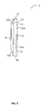
- each outer end member 1 is substantially plate-shaped in the supply condition and has at least two sections, in the embodiment shown two sections 11, 12, separated by a weakening line 10.
- the weakening line 10 may in principle take any form allowing bending or folding of the outer end member 1 and may even be in the form of a hinge, for instance a piano hinge.
- the weakening line 10 is formed by perforation.
- the length of the two sections 11, 12 is the same in the embodiment shown. Typically, the length, exemplified by the distance between end edges 12a and 12b, is slightly less than the width of a window.
- Such windows come in many different dimensions, and the kit of parts may of course be provided in as many sizes as there are various widths.
- the length thus typically lies in the interval of 50 to 100 cm. Most often, the width of the window will be slightly smaller than the typical distance between rafters, i.e. 60-80 cm.
- a number of slits 13 is provided in one section 11, these slits 13 serve to accommodate hooks 19 (cf. the mounted position in Figs 7 and 10 ) adapted to serve as engagement means to engage with the window frame, by introduction into a groove in the window frame.
- two slits 14, 15 are provided at each end of the other section 12. These slits 14, 15 serve as engagement means to engage with corresponding engagement means of the extent members 3 to be described in further detail below.
- An area 18 of the other section 12 is limited by two cuts 16, 17 and may be folded back.
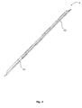
- each inner end member 2 is substantially plate-shaped in the supply condition and has at least three sections 21, 22, 23 separated by weakening lines 20 and 24, here in the form of a perforation.
- two extent members 3 are rotatably connected to the respective inner end member 2, and the first section 21 is provided with connecting means 27, 28 for connection to corresponding extent member 3 in a rotatable manner (cf. Figs 6 and 9 ).
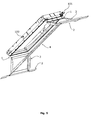
- the extent members 3 are formed as a pair of mirror-inverted telescopic L-shaped profiles, each pair comprising a base 31 and an extent piece 32.
- the base 31 has two legs 31 a and 31 b forming the L-shape meeting at a line 35, and a folded flange 33 and 34 on the respective leg 31 a and 31 b forms engagement means allowing the telescoping movement of sliding the extent piece 32 with corresponding legs 32a and 32b along.
- the extent member 3 of Fig. 3 is the left-hand lower extent member of Fig. 5 , i.e. the extent member 3 connected by connecting means 36 to connecting means 27 of the inner end member 2.
- a corresponding, but mirror-inverted extent member 3 is connected in a similar manner to the other connecting means 28, and at the other inner end member of the set, a pair of extent members 3 is connected in a similar manner.
- the connection may be carried out in any suitable manner allowing rotation of the extent member 3 relative to the inner end member 2.
- the extent members 3 could also be connected to the outer inner end member 1 in the supply condition, or be provided separately.
- each extent member is provided with engagement means formed as a tab or tongue 37 to engage with a respective slit 14, 15 of each end of the outer end member 1.
- the dimensions of the inner end member 2 are chosen such that the length of the first section 21 between end edges 21 a and 21 b corresponds to or is slightly smaller than the width of a window, for instance of a range of windows, and thus corresponds to the length of the outer end member 1.
- the length of the second and third sections 22, 23 may be identical to each other or differ, but are longer than the first section 21. The reason is that the second and third sections 22, 23 are to be fastened to the roof structure on each outer side of ends 21 a and 21 b of the first section 21 as will be described in further detail below.
- the length of the extent member 3 with its two telescopically movable parts is such that it is able to accommodate most distances from a window frame to the inner wall at the top and to a horizontal wall below the window frame at the bottom, regardless of the inclination of the roof and of the inner wall.
- the length of each of the base 31 and the extent piece 32 is 30 to 50 cm, thus being able to span distances in the range from 30 to 100 cm. It is also possible to make each part of the extent member 3 shorter and add more parts to increase the range.
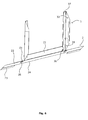
- each side member 4 is formed as pair of mirror-inverted telescopic L-shaped profiles 41 and 42.
- the structure of the side members corresponds in substance to that of the extent members 3, and thus comprises means for allowing translational relative movement.
- Engagement means of each side member 4 is formed as a tab or tongue 44 and 45 to engage with a respective slit 25, 26 at each end of the inner end member 2, cf. Fig. 12 and 13 , respectively.
- the length of the side member 4 with its two telescopically movable parts is such that it is able to accommodate most distances at the inner wall, regardless of the inclination of the roof and of the inner wall.
- the length of each of the base 41 and the extent piece 42 is 80 to 160 cm, thus being able to span distances in the range from 80 to 320 cm. It is also possible to make each part of the extent member 4 shorter and add more parts to increase the range.
- Figs 5 to 18 Details of the mounting of the kit of parts in a roof structure to provide a window lining are shown in Figs 5 to 18 .
- the roof structure comprises further elements, such as for instance further rafters, laths or battens, underroofing, insulating material, roofing etc.
- the outer and inner sets of end members, the extent members and the side members are in a mounted condition, in which they form a trapezoidal prism shape.
- a trapezoid is formed, forming the base of the right trapezoid prism and having as its sides substantially the length of one side piece of the window frame itself, the extent member 3 at the bottom, the side member 4, and the extent member 3 at the top.
- the lengths of the sides of the trapezoid vary in accordance with the height of the window (i.e. the length of the side piece), the inclination of the roof and the inner wall, the thickness of the roof structure, the distance to the horizontal surface below the window, and of course the desired inclination of the window lining parts at the top and bottom of the window, which need not be substantially horizontal and vertical, respectively, as shown.
- the height of the prism corresponds to the length of the outer end member 1 and the first section 21 of the inner end member 2.
- the inventive method of providing a window lining using said kit of parts comprises the steps of:
- each extent member 3 is rotated to approximately 90° relative to the inner end member 1 before carrying out step d) i). This applies in particular to the embodiment, in which the set of extent members 3 is connected to the set of inner end members 2 in the state of supply
- step d)i) of connecting a respective end member 1 of the outer set to a respective end member 2 of the inner set by means of at least one extent member 3 is carried out, which in an embodiment may take place at a distance from the installation site, thus forming a unit which is shown in the mounted condition in Figs 8 and 11 , respectively.
- the two sections 11, 12 of the outer end member 1 are folded about the weakening line 10 during step d) ii). Further, the three sections 21, 22, 23 of the inner end member 2 are folded about weakening lines 20, 24 during step d) iii), and the third section 23 of the inner end member 2 is cut before carrying out step d iii).
- the outer end members 1 are connected to the frame, which in the embodiment described in the above comprises a recess or groove for receiving the engagement means, that is in the embodiment shown hooks 19.
- the inner end members 2 may be connected to the roof structure, i.e. here the rafters 200, in any suitable manner, typically by screws, nails or staples.
- the set of panels 300 may be connected to the components of the kit of parts in any suitable manner, typically by means of countersunk screws that are subsequently filled with putty to provide the smooth surface aimed at.
- Fig. 19 corresponds in substance to Fig. 5 and thus shows the parts of the kit of parts according to the invention in one further embodiment in the mounted position relative to the window 100. Only the left-hand side member 4 has been omitted for clarity reasons.
- Fig. 20 shows an enlarged partial view of the lower inner end member 2 and its adjoining extent members 3 and the right-hand side member 4.
- an opposite section 23' is present at both ends of the inner end member 2.
- the third section 23 and the opposite section 23' may be bent by a slight angle, for instance 3-5°, in order to increase the stiffness of the inner end member 2, which in turn facilitates the installation, as the inner end members 2 are thus easier to handle.
- the bend may either be present already in the supply condition, but may also be carried out as an initial step in the mounting process.
- the engagement between the side member 4 and the inner end member 2 is also slightly different, in that the tab or tongue (not shown) on the side member is introduced into a pocket generally designated 26' and formed in the inner side member 2.
- FIG. 20 A further difference shown in Fig. 20 is the form of the extent member 3, which now comprises the base 31' and the extent piece 32' as in the first embodiment, however, of different lengths and configurations.
- the base 31' is relatively short and accommodates, as before the extent piece 32'.
- the extent piece 32' has, in the supply condition, a substantially longer extension than the base 31' and may be provided with a substantial length as the length is adapted to the precise distance required by translating the extent piece 32' relative to the base 31' and subsequently cutting the extent piece 32' to the desired length.
- the inner end member 2 is provided with an aperture 29.
- This embodiment makes it possible to provide the kit of parts according to the invention for covering a wide variety of roof thicknesses and inner wall inclinations.
- the first section 21' has a slightly longer extension than in the first embodiment, i.e. the entire inner end member 2 is wider.
- the end portion of the first section 21' forms an abutment for the side members 4 at either side which in turn eases the mounting.
- Figs 21 and 22 showing the kit with and without the window frame 100, respectively, details of the outer end member 1 will be described.
- the two sections 11, 12 are formed by roll-forming and have a separate end element 15', 16' at each end.
- the separate end element 15', 16' is connected to the sections 11, 12 by means of for instance rivets (not shown in detail).
- the end element comprises a first portion 15' forming the connection to the extent member 3, and a second portion 16' forming the connection to the window, partly in a flange to extend into a groove in the side members of the frame 100, partly by engagement means 19 which are provided with openings formed by a tool to provide a jagged edge which secures at least temporary retention to the window.
- This allows the installer to leave the kit while for instance reaching out for tools to provide more permanent fastening of the kit to the window, for instance by screwing.
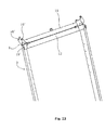
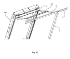
- Figs 23 , 24 and 25 show the upper portion of the kit, with and without the window frame, respectively.
- the inner end member 2, the outer end member 1, the extent members 3 and the side members 4 are formed and connected to each other in a corresponding manner as described in connection with Figs 21 and 22 .
- An additional element 39 extending between the left-hand and the right-hand extent member 3 provides additional stiffness and stability.
- the side member 4 may as mentioned in the above also be formed with more parts than the two shown in Fig. 4 , for instance by three members telescoping within each other as suggested in for instance Fig. 19 .
- the greater range of lengths of the side members and the extent members 3 makes it possible to accommodate larger wall thicknesses, for instance up to 550 mm.
- the method of providing the lining may be supplemented by the initial step of forming an aperture in the plate or sheet forming the inner wall, for instance gypsum.
- the aperture needs not correspond exactly to the finished light opening, but may be adapted in a further step.
- the upper and lower units are formed substantially as described in the above, but the extent piece 32' of each extent member 3 is then cut to an approximate measure using measured values and is connected to the base 31' once the inner and outer end members 2, 1 have been installed. As the inner end members 2 may not be fastened to the inwards facing sides of the rafters, the inner end members 2 are bent to a desired extent and then fastened to sides of the rafters.
- a vapour barrier collar is advantageously mounted beforehand, and may now be cut to the precise size by the guidance provided by the kit of parts. Following the cutting, the edges of the vapour barrier collar may be folded and taped to the side members 4.
- the roof structure comprises, in addition to rafters, of which one rafter 200 is shown, vertical beams of which one beam 250 is shown.
- the lower one of the set of inner end members 2 is positioned at a distance from the transition between the vertical beam 250 and the rafter 200 indicated as x mm.
- a cut 49 is carried out in the side member at a distance x from the end portion of the side member. The cut 49 is only present in one portion of the side member 4 to provide a coherent folding line 49.
Landscapes
- Engineering & Computer Science (AREA)
- Architecture (AREA)
- Civil Engineering (AREA)
- Structural Engineering (AREA)
- Conveying And Assembling Of Building Elements In Situ (AREA)
Abstract
Description
- The present invention provides for a kit of parts for mounting a window lining. The invention furthermore relates to a method of providing a window lining using said kit of parts.
- When installing windows in a façade or a roof, it is desirable to make the transition between the window frame and the inner wall of the room of the building smooth and of a pleasant appearance. The transition is most often made up of a so-called window lining having dimensions to span the distance between the inner side of the window frame to the inner wall. In windows installed in a facade, i.e. substantially vertically, the lining is constituted basically of a box-shaped element having two side members, a top member and a bottom member, all being of a substantially rectangular shape and positioned at right angles to the window frame. The members are traditionally formed of panels or plates of such materials as plywood, gypsum or chipboard.
- In windows mounted in an inclined roof, the geometry of the lining is more complicated. Basically, the side members are positioned at right angles to the window frame, as in facade windows, but the top member is most often virtually horizontal and the bottom member vertical, or the top and bottom assume other angles with the window frame. A number of grounds for this particular design exists, one being that the horizontal top member allows for an increased influx of light, another that the vertical bottom member makes it possible to access the bottom window and optimise the space of the room. Thus, the top member and the bottom member form an angle other than 90° with the window frame, and the side members have a trapezoidal shape.
- The adaptation of the shape of the members of the lining is relatively challenging, as the dimensions of each member rely on factors such as the inclination of the roof and the thickness of the wall. This is even more pronounced in new buildings or in buildings undergoing a complete renovation, in which the inner wall is not yet present, or to be replaced wholly or partly. In those cases, there might thus be no inner wall to start with, and the craftsman is faced with the further challenge of visualising the aperture in the inner wall before or during the installation of such inner wall.
- In the prior art, a number of solutions have been proposed to facilitate the installation and reduce the amount of manual adaptation and risk of incorrect installation. Examples are shown for instance in
EP 17 399EP 414 567 EP 287 362 - With this background it is an object of the invention to provide a kit for the mounting of a window lining, which is easy and uncomplicated to manufacture and use.
- In a first aspect, this and further objects are met by a kit of parts comprising a set of outer end members adapted to be connected to the frame of a window, a set of inner end members adapted to be connected to the roof structure, a set of extent members adapted to be connected to the set of outer end members and to the set of inner end members, and a set of side members adapted to be connected to the set of inner end members, the sets of outer and inner end members, the set of extent members and the set of side members being adapted to be brought from a supply condition to a mounted condition, in which they form a trapezoidal prism shape.
- In this manner, a supporting frame is constructed and spans the thickness of the roof structure, from the window frame to a position defining for instance the inner wall. The supporting frame may then be used for fastening plate members to finish the window lining.
- In a second aspect of the invention, a method of providing a window lining using said kit of parts, is provided, the method comprising the steps of:
- a) providing a window with a window frame,
- b) mounting said window frame in a roof structure,
- c) providing a kit of parts comprising a set of outer end members, a inner set of inner end members, a set of extent members and a set of side members in a supply condition,
- d) bringing said kit of parts from the supply condition to a mounted condition by
- i) connecting a respective end member of the outer set to a respective end member of the inner set by means of at least one extent member,
- ii) connecting the end members of the outer set to the window frame,
- iii) connecting the end members of the inner set to the roof structure,
- iv) connecting the side members to the end members of the outer set,
- e) providing a set of panels of shapes corresponding substantially to the shapes of the corresponding areas delimited by the window frame, the inner end members and the side members, and
- f) connecting the set of panels at least to the inner end members and the side members.
- Further embodiments and advantages are set forth in the dependent claims.
- In the following the invention will be described in further detail by means of examples of embodiments with reference to the schematic drawings, in which
-
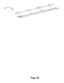
Fig. 1 is a perspective view of a detail of one embodiment of the kit of parts according to the invention in a supply condition; -
Fig. 2 is a perspective view of another detail of one embodiment of the kit of parts according to the invention in a supply condition; -
Fig. 3 is a perspective view of another detail of one embodiment of the kit of parts according to the invention; -
Fig. 4 is a perspective view of another detail of one embodiment of the kit of parts according to the invention; -
Fig. 5 is a perspective view of details of one embodiment of the kit of parts according to the invention in a mounted condition; -
Fig. 6 is a perspective view of details of one embodiment of the kit of parts according to the invention during mounting; -
Fig. 7 is a perspective view of details of one embodiment of the kit of parts according to the invention during mounting; -
Fig. 8 is a perspective view of details of one embodiment of the kit of parts according to the invention during mounting; -
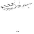
Figs 9 to 11 are views corresponding toFigs 6 to 8 ; -
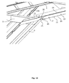
Figs 12 and13 are partial perspective views, on a larger scale, of details ofFig. 5 ; -
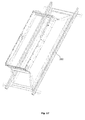
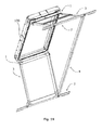
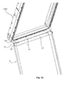
Figs 14 to 18 show perspective views of an embodiment of a kit of parts according to the invention during steps of mounting by means of the method of providing a window lining according to the invention; -
Figs 19 to 25 show perspective views of another embodiment of a kit of parts according to the invention; and -
Figs 26 to 28 show schematic perspective views of yet another embodiment of a kit of parts according to the invention. - Referring first to
Figs 1 to 4 , the components of an embodiment of the kit of parts according to the invention will be described in detail, starting from a supply condition. Basically, the kit of parts comprises a set ofouter end members 1 adapted to be connected to the frame of a window, a set ofinner end members 2 adapted to be connected to a roof structure, a set ofextent members 3 adapted to be connected to the set ofouter end members 1 and the set ofinner end members 2, and a set ofside members 4 adapted to be connected to the set ofinner end members 2. - Turning to
Fig. 5 , the respective positions of the set ofouter end members 1, the set ofinner end members 2, the set ofextent members 3 and the set ofside members 4 are shown in a mounted condition relative to awindow frame 100. Thewindow frame 100 is fastened to the roof structure (not shown inFig. 5 ) by means of a number ofmounting brackets 101, of which one only is shown inFig. 5 . As is apparent fromFig. 5 , oneouter end member 1 of the outer set is positioned at the bottom of thewindow frame 100 and one at the top. Correspondingly, oneinner end member 2 is positioned below the window frame and the other at the top of thewindow frame 100. Twoextent members 3 of the set of extent members span the distance between each pair of inner and outer end members. The set ofside members 4, of which one only is shown inFig. 5 , spans the distance between the lower and the upperinner end member 2 and extends substantially in parallel with the side pieces of the window frame, i.e. the pieces extending in the direction of the inclination of the roof. In the embodiment shown, there are two members of the inner and outer set, viz. oneouter end member 1 at the top and one at the bottom, and oneinner end member 2 at the top and one at the bottom. Furthermore, in the embodiment shown, there are four extent members in all; two connecting theouter end member 1 to theinner end member 2 at the top, and a corresponding arrangement at the bottom. Eventually, there are twoside members 4, one at either side of the window. - As shown in
Fig. 1 , eachouter end member 1 is substantially plate-shaped in the supply condition and has at least two sections, in the embodiment shown twosections weakening line 10. The weakeningline 10 may in principle take any form allowing bending or folding of theouter end member 1 and may even be in the form of a hinge, for instance a piano hinge. In the embodiment shown, theweakening line 10 is formed by perforation. The length of the twosections end edges slits 13 is provided in onesection 11, theseslits 13 serve to accommodate hooks 19 (cf. the mounted position inFigs 7 and10 ) adapted to serve as engagement means to engage with the window frame, by introduction into a groove in the window frame. At each end of theother section 12, twoslits slits extent members 3 to be described in further detail below. Anarea 18 of theother section 12 is limited by twocuts - Referring now to
Figs 2 and3 , oneinner end member 2 and oneextent member 3 will be described. - As shown in
Fig. 2 , eachinner end member 2 is substantially plate-shaped in the supply condition and has at least threesections lines extent members 3 are rotatably connected to the respectiveinner end member 2, and thefirst section 21 is provided with connectingmeans extent member 3 in a rotatable manner (cf.Figs 6 and9 ). It is noted that theextent members 3 are formed as a pair of mirror-inverted telescopic L-shaped profiles, each pair comprising abase 31 and anextent piece 32. Thebase 31 has twolegs line 35, and a foldedflange respective leg extent piece 32 withcorresponding legs - It is noted that the
extent member 3 ofFig. 3 is the left-hand lower extent member ofFig. 5 , i.e. theextent member 3 connected by connectingmeans 36 to connectingmeans 27 of theinner end member 2. A corresponding, but mirror-invertedextent member 3 is connected in a similar manner to the other connectingmeans 28, and at the other inner end member of the set, a pair ofextent members 3 is connected in a similar manner. The connection may be carried out in any suitable manner allowing rotation of theextent member 3 relative to theinner end member 2. Theextent members 3 could also be connected to the outerinner end member 1 in the supply condition, or be provided separately. Eventually, each extent member is provided with engagement means formed as a tab ortongue 37 to engage with arespective slit outer end member 1. - The dimensions of the
inner end member 2 are chosen such that the length of thefirst section 21 between end edges 21 a and 21 b corresponds to or is slightly smaller than the width of a window, for instance of a range of windows, and thus corresponds to the length of theouter end member 1. The length of the second andthird sections first section 21. The reason is that the second andthird sections first section 21 as will be described in further detail below. The length of theextent member 3 with its two telescopically movable parts is such that it is able to accommodate most distances from a window frame to the inner wall at the top and to a horizontal wall below the window frame at the bottom, regardless of the inclination of the roof and of the inner wall. Typically, the length of each of thebase 31 and theextent piece 32 is 30 to 50 cm, thus being able to span distances in the range from 30 to 100 cm. It is also possible to make each part of theextent member 3 shorter and add more parts to increase the range. - As shown in
Fig. 4 indicating the supply condition, andFigs 5 and12-13 showing the mounted condition, eachside member 4 is formed as pair of mirror-inverted telescopic L-shapedprofiles extent members 3, and thus comprises means for allowing translational relative movement. Engagement means of eachside member 4 is formed as a tab ortongue respective slit inner end member 2, cf.Fig. 12 and13 , respectively. The length of theside member 4 with its two telescopically movable parts is such that it is able to accommodate most distances at the inner wall, regardless of the inclination of the roof and of the inner wall. Typically, the length of each of thebase 41 and theextent piece 42 is 80 to 160 cm, thus being able to span distances in the range from 80 to 320 cm. It is also possible to make each part of theextent member 4 shorter and add more parts to increase the range. - Details of the mounting of the kit of parts in a roof structure to provide a window lining are shown in
Figs 5 to 18 . Of the roof structure, only tworafters 200 are shown. It is clear that the roof structure comprises further elements, such as for instance further rafters, laths or battens, underroofing, insulating material, roofing etc. In one of the last stages of mounting of the kit of parts, shown inFigs 5 and18 , the outer and inner sets of end members, the extent members and the side members are in a mounted condition, in which they form a trapezoidal prism shape. At each side of thewindow frame 100, a trapezoid is formed, forming the base of the right trapezoid prism and having as its sides substantially the length of one side piece of the window frame itself, theextent member 3 at the bottom, theside member 4, and theextent member 3 at the top. It is clear to the person skilled in the art that the lengths of the sides of the trapezoid vary in accordance with the height of the window (i.e. the length of the side piece), the inclination of the roof and the inner wall, the thickness of the roof structure, the distance to the horizontal surface below the window, and of course the desired inclination of the window lining parts at the top and bottom of the window, which need not be substantially horizontal and vertical, respectively, as shown. The height of the prism corresponds to the length of theouter end member 1 and thefirst section 21 of theinner end member 2. - Basically, the inventive method of providing a window lining using said kit of parts, comprises the steps of:
- a) providing a window with a window frame,
- b) mounting said window frame in a roof structure,
- c) providing a kit of parts comprising a set of outer end members, a inner set of inner end members, a set of extent members and a set of side members in a supply condition,
- d) bringing said kit of parts from the supply condition to a mounted condition by
- i) connecting a respective end member of the outer set to a respective end member of the inner set by means of at least one extent member,
- ii) connecting the end members of the outer set to the window frame,
- iii) connecting the end members of the inner set to the roof structure,
- iv) connecting the side members to the end members of the outer set,
- e) providing a set of panels of shapes corresponding substantially to the shapes of the corresponding areas delimited by the window frame, the inner end members and the side members, and
- f) connecting the set of panels at least to the inner end members and the side members.
- In one example of the method, as an initial step, each
extent member 3 is rotated to approximately 90° relative to theinner end member 1 before carrying out step d) i). This applies in particular to the embodiment, in which the set ofextent members 3 is connected to the set ofinner end members 2 in the state of supply - Subsequently, step d)i) of connecting a
respective end member 1 of the outer set to arespective end member 2 of the inner set by means of at least oneextent member 3 is carried out, which in an embodiment may take place at a distance from the installation site, thus forming a unit which is shown in the mounted condition inFigs 8 and11 , respectively. - In this embodiment, the two
sections outer end member 1 are folded about the weakeningline 10 during step d) ii). Further, the threesections inner end member 2 are folded about weakeninglines third section 23 of theinner end member 2 is cut before carrying out step d iii). - The
outer end members 1 are connected to the frame, which in the embodiment described in the above comprises a recess or groove for receiving the engagement means, that is in the embodiment shown hooks 19. Other configurations are of course possible (for instance as shown in the other embodiment to be described), as long as it is possible to define the position of theouter end members 1 relative to thewindow frame 100. Theinner end members 2 may be connected to the roof structure, i.e. here therafters 200, in any suitable manner, typically by screws, nails or staples. Correspondingly, the set ofpanels 300 may be connected to the components of the kit of parts in any suitable manner, typically by means of countersunk screws that are subsequently filled with putty to provide the smooth surface aimed at. - Referring now to
Figures 19 to 28 , other embodiments of the kit of parts will be described. Only differences relative to the first embodiment will be described in detail. -
Fig. 19 corresponds in substance toFig. 5 and thus shows the parts of the kit of parts according to the invention in one further embodiment in the mounted position relative to thewindow 100. Only the left-hand side member 4 has been omitted for clarity reasons. -
Fig. 20 shows an enlarged partial view of the lowerinner end member 2 and its adjoiningextent members 3 and the right-hand side member 4. - As indicated, in addition to the
third section 23, an opposite section 23' is present at both ends of theinner end member 2. Thethird section 23 and the opposite section 23' may be bent by a slight angle, for instance 3-5°, in order to increase the stiffness of theinner end member 2, which in turn facilitates the installation, as theinner end members 2 are thus easier to handle. The bend may either be present already in the supply condition, but may also be carried out as an initial step in the mounting process. - The engagement between the
side member 4 and theinner end member 2 is also slightly different, in that the tab or tongue (not shown) on the side member is introduced into a pocket generally designated 26' and formed in theinner side member 2. - A further difference shown in
Fig. 20 is the form of theextent member 3, which now comprises the base 31' and the extent piece 32' as in the first embodiment, however, of different lengths and configurations. The base 31' is relatively short and accommodates, as before the extent piece 32'. However, the extent piece 32' has, in the supply condition, a substantially longer extension than the base 31' and may be provided with a substantial length as the length is adapted to the precise distance required by translating the extent piece 32' relative to the base 31' and subsequently cutting the extent piece 32' to the desired length. To this end, theinner end member 2 is provided with anaperture 29. This embodiment makes it possible to provide the kit of parts according to the invention for covering a wide variety of roof thicknesses and inner wall inclinations. - Eventually, it is shown how the first section 21' has a slightly longer extension than in the first embodiment, i.e. the entire
inner end member 2 is wider. The end portion of the first section 21' forms an abutment for theside members 4 at either side which in turn eases the mounting. - Turning now to
Figs 21 and22 showing the kit with and without thewindow frame 100, respectively, details of theouter end member 1 will be described. First, it is noted that the twosections sections extent member 3, and a second portion 16' forming the connection to the window, partly in a flange to extend into a groove in the side members of theframe 100, partly by engagement means 19 which are provided with openings formed by a tool to provide a jagged edge which secures at least temporary retention to the window. This allows the installer to leave the kit while for instance reaching out for tools to provide more permanent fastening of the kit to the window, for instance by screwing. -
Figs 23 ,24 and25 show the upper portion of the kit, with and without the window frame, respectively. Theinner end member 2, theouter end member 1, theextent members 3 and theside members 4 are formed and connected to each other in a corresponding manner as described in connection withFigs 21 and22 . Anadditional element 39 extending between the left-hand and the right-hand extent member 3 provides additional stiffness and stability. - The
side member 4 may as mentioned in the above also be formed with more parts than the two shown inFig. 4 , for instance by three members telescoping within each other as suggested in for instanceFig. 19 . - The greater range of lengths of the side members and the
extent members 3 makes it possible to accommodate larger wall thicknesses, for instance up to 550 mm. - Even though the kit of parts is advantageous in situations in which no inner wall is yet present, it is also particularly easy to install when an inner wall has already been mounted. In such a situation, the method of providing the lining may be supplemented by the initial step of forming an aperture in the plate or sheet forming the inner wall, for instance gypsum. The aperture needs not correspond exactly to the finished light opening, but may be adapted in a further step.
- The upper and lower units are formed substantially as described in the above, but the extent piece 32' of each
extent member 3 is then cut to an approximate measure using measured values and is connected to the base 31' once the inner andouter end members inner end members 2 may not be fastened to the inwards facing sides of the rafters, theinner end members 2 are bent to a desired extent and then fastened to sides of the rafters. - A vapour barrier collar is advantageously mounted beforehand, and may now be cut to the precise size by the guidance provided by the kit of parts. Following the cutting, the edges of the vapour barrier collar may be folded and taped to the
side members 4. - Referring now to
Figs 26 to 28 , a slightly varied manner of installing the kit of parts of the embodiment shown inFigs 19 to 25 is shown. The roof structure comprises, in addition to rafters, of which onerafter 200 is shown, vertical beams of which onebeam 250 is shown. The lower one of the set ofinner end members 2 is positioned at a distance from the transition between thevertical beam 250 and therafter 200 indicated as x mm. In order to allow theside members 4 to be connected to the set ofinner end members 2 by introducing tab ortongue 44 into pocket 26' and still provide the adaptation to therafter 200 and hence the inclination of the inner wall, acut 49 is carried out in the side member at a distance x from the end portion of the side member. Thecut 49 is only present in one portion of theside member 4 to provide acoherent folding line 49. - The invention should not be regarded as being limited to the embodiments shown in the drawings and described in the above. Various modifications and combinations may be carried out within the scope of the appended claims.
- The following is a list of itemized further embodiments:
- 1. A kit of parts for mounting a window lining on a window installed in a roof structure, comprising a set of outer end members (1) adapted to be connected to the frame (100) of a window, characterized in further comprising a set of inner end members (2) adapted to be connected to the roof structure (200), a set of extent members (3) adapted to be connected to the set of outer end members (1) and to the set of inner end members (2), and a set of side members (4) adapted to be connected to the set of inner end members (2), the sets of outer and inner end members, the set of extent members and the set of side members being adapted to be brought from a supply condition to a mounted condition, in which they form a trapezoidal prism shape.
- 2. A kit of parts according to
embodiment 1, wherein each outer end member (1) is substantially plate-shaped in the supply condition and has at least two sections (11, 12) separated by a weakening line (10), preferably in the form of a perforation. - 3. A kit of parts according to
embodiment - 4. A kit of parts according to any one of the preceding embodiments, wherein each extent member (3) is formed as a pair of mirror-inverted telescopic L-shaped profiles, each pair comprising a base (31) and an extent piece (32).
- 5. A kit of parts according to any one of the preceding embodiments, wherein each outer end member (1) is provided with engagement means (14, 15) to engage with corresponding engagement means (37) of the extent members (3), preferably in the form of at least two slits (14, 15) and a tab or tongue (37), respectively.
- 6. A kit of parts according to any one of the preceding embodiments, wherein each outer end member (1) is provided with engagement means to engage with the window frame (100), preferably in the form of a separate end element (15', 16') at each end, or in the form of protruding hooks (19) for introduction into a groove in the window frame (100).
- 7. A kit of parts according to any one of the preceding embodiments, wherein each side member (4) is formed as pair of mirror-inverted telescopic L-shaped profiles (41, 42), each set comprising a base and an extent piece.
- 8. A kit of parts according to embodiment 7, wherein each inner end member (2) is provided with engagement means (25, 26; 26') to engage with corresponding engagement means (44, 45) of the side members (4), preferably in the form of at least two slits (25, 26) or pockets (26') and a tab or tongue (44, 45), respectively.
- 9. A kit of parts according to any one of the preceding embodiments, wherein the set of extent members (3) is connected to the set of inner end members (2) in the state of supply.
- 10. Method of providing a window lining using said kit of parts, comprising the steps of:
- a) providing a window with a window frame,
- b) mounting said window frame in a roof structure,
- c) providing a kit of parts comprising a set of outer end members, a inner set of inner end members, a set of extent members and a set of side members in a supply condition,
- d) bringing said kit of parts from the supply condition to a mounted condition by
- i) connecting a respective end member of the outer set to a respective end member of the inner set by means of at least one extent member,
- ii) connecting the end members of the outer set to the window frame,
- iii) connecting the end members of the inner set to the roof structure,
- iv) connecting the side members to the end members of the outer set,
- e) providing a set of panels of shapes corresponding substantially to the shapes of the corresponding areas delimited by the window frame, the inner end members and the side members, and
- f) connecting the set of panels at least to the inner end members and the side members.
- 11. The method of
embodiment 10, wherein step d) i) of connecting a respective end member of the outer set to a respective end member of the inner set by means of at least one extent member is carried out at a distance from the installation site. - 12. The method of
embodiment - 13. The method of any one of
embodiments 10 to 12, wherein each inner end member is substantially plate-shaped in the supply condition and has at least three sections separated by weakening lines, preferably in the form of a perforation, wherein the three sections are folded about said weakening lines during step d) iii). - 14. The method of
embodiment 13, wherein at least one section of the inner end member is cut before carrying out step d iii). - 15. The method of any one of
embodiments 10 to 14, wherein each extent member is rotatably connected to each inner end member, wherein the extent members are rotated to approximately 90° relative to the first part before carrying out step d) i).
Claims (12)
- A set of panels (300) comprising plate members including a top member, a bottom member and two side members adapted to cooperate with a supporting frame to form a window lining spanning a thickness of a roof structure (200) from a window frame (100) of a window, characterized in that the shape of the plate members is defined by the shape of the supporting frame.
- A set of panels (300) according to claim 1, wherein the supporting frame is formed by a kit of parts comprising a set of outer end members (1) adapted to be connected to the window frame (100), a set of inner end members (2) adapted to be connected to the roof structure (200), a set of extent members (3) adapted to be connected to the set of outer end members (1) and to the set of inner end members (2), and a set of side members (4) adapted to be connected to the set of inner end members (2).
- A set of panels (300) according to claim 2, wherein the length of each outer end member (1) is slightly less than the width of the window, preferably 50 to 100 cm, more preferably 60 to 80 cm.
- A set of panels (300) according to claim 2 or 3, wherein the length of at least a part of each inner end member (2) corresponds to the width of the window.
- A set of panels (300) according to any one of claims 2 to 4, wherein each extent member (3) is formed by at least two telescopically movable parts spanning a predefined distance, preferably in the range 30 to 100 cm.
- A set of panels (300) according to any one of claims 2 to 5, wherein each side member (4) is formed by at least two telescopically movable parts spanning a predefined distance, preferably in the range 80 to 360 cm.
- A set of panels (300) according to any one of the preceding claims, wherein the sets of outer and inner end members, the set of extent members and the set of side members being adapted to be brought from a supply condition to a mounted condition.
- A set of panels (300) according to claim 7, wherein the set of panels (300) is connected to the supporting frame in the mounted condition.
- Method of installing a set of panels (300) to form a window lining of a window with a window frame in a roof structure by means of a supporting frame, comprising the steps of
providing a supporting frame,
shaping a set of panels comprising plate members including a top member, a bottom member and two side members of shapes defined by the shape of the supporting frame, and
connecting the set of panels (300) to the supporting frame. - The method of claim 9, wherein the step of providing the supporting frame includes providing a kit of parts comprising a set of outer end members (1) adapted to be connected to the window frame (100), a set of inner end members (2) adapted to be connected to the roof structure (200), a set of extent members (3) adapted to be connected to the set of outer end members (1) and to the set of inner end members (2), and a set of side members (4) adapted to be connected to the set of inner end members (2).
- The method of claim 10, wherein the sets of outer and inner end members, the set of extent members and the set of side members are supplied in a supply condition and brought to a mounted condition at an installation site.
- The method of claim 11, wherein the set of panels (300) is connected to the supporting frame in the mounted condition.
Applications Claiming Priority (3)
| Application Number | Priority Date | Filing Date | Title |
|---|---|---|---|
| DKPA201270022A DK201270022A (en) | 2012-01-13 | 2012-01-13 | A kit of parts for mounting a window lining and method of providing a window lining using said kit of parts |
| DKPA201270359 | 2012-06-25 | ||
| EP13150943.2A EP2615219B1 (en) | 2012-01-13 | 2013-01-11 | A kit of parts for mounting a window lining and method of providing a window lining using said kit of parts |
Related Parent Applications (1)
| Application Number | Title | Priority Date | Filing Date |
|---|---|---|---|
| EP13150943.2A Division EP2615219B1 (en) | 2012-01-13 | 2013-01-11 | A kit of parts for mounting a window lining and method of providing a window lining using said kit of parts |
Publications (1)
| Publication Number | Publication Date |
|---|---|
| EP2913455A1 true EP2913455A1 (en) | 2015-09-02 |
Family
ID=47563200
Family Applications (2)
| Application Number | Title | Priority Date | Filing Date |
|---|---|---|---|
| EP15159231.8A Withdrawn EP2913455A1 (en) | 2012-01-13 | 2013-01-11 | A set of panels comprising plate members and method of installing such a set of panels |
| EP13150943.2A Active EP2615219B1 (en) | 2012-01-13 | 2013-01-11 | A kit of parts for mounting a window lining and method of providing a window lining using said kit of parts |
Family Applications After (1)
| Application Number | Title | Priority Date | Filing Date |
|---|---|---|---|
| EP13150943.2A Active EP2615219B1 (en) | 2012-01-13 | 2013-01-11 | A kit of parts for mounting a window lining and method of providing a window lining using said kit of parts |
Country Status (4)
| Country | Link |
|---|---|
| EP (2) | EP2913455A1 (en) |
| DK (1) | DK2615219T3 (en) |
| PL (1) | PL2615219T3 (en) |
| RU (1) | RU2599391C2 (en) |
Families Citing this family (5)
| Publication number | Priority date | Publication date | Assignee | Title |
|---|---|---|---|---|
| DK201300157U4 (en) | 2013-10-10 | 2015-01-23 | Vkr Holding As | Measuring tool for preparing a window lighting panel |
| EP4219855A1 (en) | 2018-06-28 | 2023-08-02 | VKR Holding A/S | Plaster board support bracket |
| DK180686B1 (en) | 2019-09-13 | 2021-11-25 | Vkr Holding As | Window lining assembly with improved fittings and method for installing such a lining assembly on a window |
| FR3122681B1 (en) * | 2021-05-06 | 2025-03-21 | Groupe Prot Securite | BASE, ESPECIALLY FOR SMOKE EXHAUST |
| PL445470A1 (en) * | 2023-07-05 | 2025-01-07 | Fakro Pp Spółka Z Ograniczoną Odpowiedzialnością | Roof window lining assembly connector, lining assembly kit and method of assembling the lining around the roof window using the assembly kit |
Citations (4)
| Publication number | Priority date | Publication date | Assignee | Title |
|---|---|---|---|---|
| DE3611899A1 (en) * | 1985-04-16 | 1986-10-30 | Berger, Erich, 7137 Sternenfels | Wooden cladding of a dormer window |
| DE3640204A1 (en) * | 1985-12-04 | 1987-06-11 | Edmund Trippner | Inner lining for dormer windows |
| US5544455A (en) * | 1994-08-12 | 1996-08-13 | Odl, Incorporated | Skylight with modular shaft |
| EP2322737A2 (en) * | 2009-06-24 | 2011-05-18 | FAKRO PP Spolka z o.o. | Finishing slat assembly for construction opening |
Family Cites Families (1)
| Publication number | Priority date | Publication date | Assignee | Title |
|---|---|---|---|---|
| WO2005049951A1 (en) * | 2003-11-21 | 2005-06-02 | Vkr Holding A/S | Drainage system in a roofwindow and roofwindow |
-
2013
- 2013-01-11 RU RU2013101562/03A patent/RU2599391C2/en not_active IP Right Cessation
- 2013-01-11 PL PL13150943T patent/PL2615219T3/en unknown
- 2013-01-11 DK DK13150943.2T patent/DK2615219T3/en active
- 2013-01-11 EP EP15159231.8A patent/EP2913455A1/en not_active Withdrawn
- 2013-01-11 EP EP13150943.2A patent/EP2615219B1/en active Active
Patent Citations (4)
| Publication number | Priority date | Publication date | Assignee | Title |
|---|---|---|---|---|
| DE3611899A1 (en) * | 1985-04-16 | 1986-10-30 | Berger, Erich, 7137 Sternenfels | Wooden cladding of a dormer window |
| DE3640204A1 (en) * | 1985-12-04 | 1987-06-11 | Edmund Trippner | Inner lining for dormer windows |
| US5544455A (en) * | 1994-08-12 | 1996-08-13 | Odl, Incorporated | Skylight with modular shaft |
| EP2322737A2 (en) * | 2009-06-24 | 2011-05-18 | FAKRO PP Spolka z o.o. | Finishing slat assembly for construction opening |
Also Published As
| Publication number | Publication date |
|---|---|
| EP2615219A1 (en) | 2013-07-17 |
| RU2013101562A (en) | 2014-07-20 |
| DK2615219T3 (en) | 2015-05-18 |
| RU2599391C2 (en) | 2016-10-10 |
| EP2615219B1 (en) | 2015-03-18 |
| PL2615219T3 (en) | 2015-08-31 |
Similar Documents
| Publication | Publication Date | Title |
|---|---|---|
| EP2615219B1 (en) | A kit of parts for mounting a window lining and method of providing a window lining using said kit of parts | |
| EP3569792B1 (en) | Wall structure for building, installation device, and board construction method | |
| US5950375A (en) | Combined fascia and soffit member roll-formed from sheet metal | |
| CA2787536C (en) | Strip with resilient braces for fastening perpendicularly attached siding panels | |
| MX2012003347A (en) | Bracket useful with sloped suspended ceiling systems. | |
| US4092808A (en) | Combination eaves trough and fascia with soffit connection means, and method of making same | |
| US10415243B2 (en) | Connecting element for wall components | |
| EP3567182B1 (en) | Wall material fixture and wall structure | |
| US7484335B1 (en) | Soffit vent assembly and method | |
| JP6814014B2 (en) | End face attachment of plate material, wall structure and construction method of plate material | |
| US12618246B2 (en) | Exterior trim system | |
| WO2011109703A2 (en) | Gable overhang structure | |
| WO2015149372A1 (en) | Combined wall and construction method therefor | |
| EP2700781B1 (en) | A window lining assembly having an improved corner fitting | |
| JP2022065160A (en) | Wall material fixture | |
| EP2860487A1 (en) | A measuring tool for preparation of a window lining, an installation kit comprising such a measuring tool, and a method for preparation of a window lining | |
| JP6029365B2 (en) | Building fence | |
| JP7211838B2 (en) | Eave structure | |
| IT202000003587A1 (en) | BOX PERFECTED FOR SHUTTERS OR SIMILAR | |
| JP6926445B2 (en) | Partition device | |
| EP3020883A1 (en) | System for mounting of wall and/or roof cladding materials and method for mounting of wall and/or roof cladding on a building structure | |
| WO2010089590A1 (en) | Door frame assembly and method of installation of doors | |
| JP7045132B2 (en) | Board fixtures and board construction methods | |
| JP6134949B2 (en) | Boarded wall structure and building exterior structure equipped with the same | |
| DK2547834T3 (en) | Air gap barrier |
Legal Events
| Date | Code | Title | Description |
|---|---|---|---|
| PUAI | Public reference made under article 153(3) epc to a published international application that has entered the european phase |
Free format text: ORIGINAL CODE: 0009012 |
|
| AC | Divisional application: reference to earlier application |
Ref document number: 2615219 Country of ref document: EP Kind code of ref document: P |
|
| AK | Designated contracting states |
Kind code of ref document: A1 Designated state(s): AL AT BE BG CH CY CZ DE DK EE ES FI FR GB GR HR HU IE IS IT LI LT LU LV MC MK MT NL NO PL PT RO RS SE SI SK SM TR |
|
| 17P | Request for examination filed |
Effective date: 20160302 |
|
| RBV | Designated contracting states (corrected) |
Designated state(s): AL AT BE BG CH CY CZ DE DK EE ES FI FR GB GR HR HU IE IS IT LI LT LU LV MC MK MT NL NO PL PT RO RS SE SI SK SM TR |
|
| 17Q | First examination report despatched |
Effective date: 20170125 |
|
| STAA | Information on the status of an ep patent application or granted ep patent |
Free format text: STATUS: THE APPLICATION HAS BEEN WITHDRAWN |
|
| 18W | Application withdrawn |
Effective date: 20170516 |