EP2911716B1 - Dispositif de traitement extra corporel du sang - Google Patents
Dispositif de traitement extra corporel du sang Download PDFInfo
- Publication number
- EP2911716B1 EP2911716B1 EP13821164.4A EP13821164A EP2911716B1 EP 2911716 B1 EP2911716 B1 EP 2911716B1 EP 13821164 A EP13821164 A EP 13821164A EP 2911716 B1 EP2911716 B1 EP 2911716B1
- Authority
- EP
- European Patent Office
- Prior art keywords
- piston
- fluid
- valve
- actuator
- bearing means
- Prior art date
- Legal status (The legal status is an assumption and is not a legal conclusion. Google has not performed a legal analysis and makes no representation as to the accuracy of the status listed.)
- Active
Links
Images


Classifications
-
- F—MECHANICAL ENGINEERING; LIGHTING; HEATING; WEAPONS; BLASTING
- F04—POSITIVE - DISPLACEMENT MACHINES FOR LIQUIDS; PUMPS FOR LIQUIDS OR ELASTIC FLUIDS
- F04B—POSITIVE-DISPLACEMENT MACHINES FOR LIQUIDS; PUMPS
- F04B43/00—Machines, pumps, or pumping installations having flexible working members
- F04B43/0009—Special features
-
- F—MECHANICAL ENGINEERING; LIGHTING; HEATING; WEAPONS; BLASTING
- F16—ENGINEERING ELEMENTS AND UNITS; GENERAL MEASURES FOR PRODUCING AND MAINTAINING EFFECTIVE FUNCTIONING OF MACHINES OR INSTALLATIONS; THERMAL INSULATION IN GENERAL
- F16K—VALVES; TAPS; COCKS; ACTUATING-FLOATS; DEVICES FOR VENTING OR AERATING
- F16K7/00—Diaphragm valves or cut-off apparatus, e.g. with a member deformed, but not moved bodily, to close the passage ; Pinch valves
- F16K7/12—Diaphragm valves or cut-off apparatus, e.g. with a member deformed, but not moved bodily, to close the passage ; Pinch valves with flat, dished, or bowl-shaped diaphragm
- F16K7/14—Diaphragm valves or cut-off apparatus, e.g. with a member deformed, but not moved bodily, to close the passage ; Pinch valves with flat, dished, or bowl-shaped diaphragm arranged to be deformed against a flat seat
- F16K7/16—Diaphragm valves or cut-off apparatus, e.g. with a member deformed, but not moved bodily, to close the passage ; Pinch valves with flat, dished, or bowl-shaped diaphragm arranged to be deformed against a flat seat the diaphragm being mechanically actuated, e.g. by screw-spindle or cam
-
- A—HUMAN NECESSITIES
- A61—MEDICAL OR VETERINARY SCIENCE; HYGIENE
- A61M—DEVICES FOR INTRODUCING MEDIA INTO, OR ONTO, THE BODY; DEVICES FOR TRANSDUCING BODY MEDIA OR FOR TAKING MEDIA FROM THE BODY; DEVICES FOR PRODUCING OR ENDING SLEEP OR STUPOR
- A61M1/00—Suction or pumping devices for medical purposes; Devices for carrying-off, for treatment of, or for carrying-over, body-liquids; Drainage systems
- A61M1/14—Dialysis systems; Artificial kidneys; Blood oxygenators ; Reciprocating systems for treatment of body fluids, e.g. single needle systems for hemofiltration or pheresis
- A61M1/15—Dialysis systems; Artificial kidneys; Blood oxygenators ; Reciprocating systems for treatment of body fluids, e.g. single needle systems for hemofiltration or pheresis with a cassette forming partially or totally the flow circuit for the treating fluid, e.g. the dialysate fluid circuit or the treating gas circuit
- A61M1/152—Details related to the interface between cassette and machine
- A61M1/1524—Details related to the interface between cassette and machine the interface providing means for actuating on functional elements of the cassette, e.g. plungers
-
- A—HUMAN NECESSITIES
- A61—MEDICAL OR VETERINARY SCIENCE; HYGIENE
- A61M—DEVICES FOR INTRODUCING MEDIA INTO, OR ONTO, THE BODY; DEVICES FOR TRANSDUCING BODY MEDIA OR FOR TAKING MEDIA FROM THE BODY; DEVICES FOR PRODUCING OR ENDING SLEEP OR STUPOR
- A61M1/00—Suction or pumping devices for medical purposes; Devices for carrying-off, for treatment of, or for carrying-over, body-liquids; Drainage systems
- A61M1/14—Dialysis systems; Artificial kidneys; Blood oxygenators ; Reciprocating systems for treatment of body fluids, e.g. single needle systems for hemofiltration or pheresis
- A61M1/15—Dialysis systems; Artificial kidneys; Blood oxygenators ; Reciprocating systems for treatment of body fluids, e.g. single needle systems for hemofiltration or pheresis with a cassette forming partially or totally the flow circuit for the treating fluid, e.g. the dialysate fluid circuit or the treating gas circuit
- A61M1/155—Dialysis systems; Artificial kidneys; Blood oxygenators ; Reciprocating systems for treatment of body fluids, e.g. single needle systems for hemofiltration or pheresis with a cassette forming partially or totally the flow circuit for the treating fluid, e.g. the dialysate fluid circuit or the treating gas circuit with treatment-fluid pumping means or components thereof
-
- A—HUMAN NECESSITIES
- A61—MEDICAL OR VETERINARY SCIENCE; HYGIENE
- A61M—DEVICES FOR INTRODUCING MEDIA INTO, OR ONTO, THE BODY; DEVICES FOR TRANSDUCING BODY MEDIA OR FOR TAKING MEDIA FROM THE BODY; DEVICES FOR PRODUCING OR ENDING SLEEP OR STUPOR
- A61M1/00—Suction or pumping devices for medical purposes; Devices for carrying-off, for treatment of, or for carrying-over, body-liquids; Drainage systems
- A61M1/14—Dialysis systems; Artificial kidneys; Blood oxygenators ; Reciprocating systems for treatment of body fluids, e.g. single needle systems for hemofiltration or pheresis
- A61M1/15—Dialysis systems; Artificial kidneys; Blood oxygenators ; Reciprocating systems for treatment of body fluids, e.g. single needle systems for hemofiltration or pheresis with a cassette forming partially or totally the flow circuit for the treating fluid, e.g. the dialysate fluid circuit or the treating gas circuit
- A61M1/156—Constructional details of the cassette, e.g. specific details on material or shape
- A61M1/1562—Details of incorporated reservoirs
-
- A—HUMAN NECESSITIES
- A61—MEDICAL OR VETERINARY SCIENCE; HYGIENE
- A61M—DEVICES FOR INTRODUCING MEDIA INTO, OR ONTO, THE BODY; DEVICES FOR TRANSDUCING BODY MEDIA OR FOR TAKING MEDIA FROM THE BODY; DEVICES FOR PRODUCING OR ENDING SLEEP OR STUPOR
- A61M1/00—Suction or pumping devices for medical purposes; Devices for carrying-off, for treatment of, or for carrying-over, body-liquids; Drainage systems
- A61M1/14—Dialysis systems; Artificial kidneys; Blood oxygenators ; Reciprocating systems for treatment of body fluids, e.g. single needle systems for hemofiltration or pheresis
- A61M1/15—Dialysis systems; Artificial kidneys; Blood oxygenators ; Reciprocating systems for treatment of body fluids, e.g. single needle systems for hemofiltration or pheresis with a cassette forming partially or totally the flow circuit for the treating fluid, e.g. the dialysate fluid circuit or the treating gas circuit
- A61M1/156—Constructional details of the cassette, e.g. specific details on material or shape
- A61M1/1565—Details of valves
-
- A—HUMAN NECESSITIES
- A61—MEDICAL OR VETERINARY SCIENCE; HYGIENE
- A61M—DEVICES FOR INTRODUCING MEDIA INTO, OR ONTO, THE BODY; DEVICES FOR TRANSDUCING BODY MEDIA OR FOR TAKING MEDIA FROM THE BODY; DEVICES FOR PRODUCING OR ENDING SLEEP OR STUPOR
- A61M1/00—Suction or pumping devices for medical purposes; Devices for carrying-off, for treatment of, or for carrying-over, body-liquids; Drainage systems
- A61M1/14—Dialysis systems; Artificial kidneys; Blood oxygenators ; Reciprocating systems for treatment of body fluids, e.g. single needle systems for hemofiltration or pheresis
- A61M1/16—Dialysis systems; Artificial kidneys; Blood oxygenators ; Reciprocating systems for treatment of body fluids, e.g. single needle systems for hemofiltration or pheresis with membranes
- A61M1/26—Dialysis systems; Artificial kidneys; Blood oxygenators ; Reciprocating systems for treatment of body fluids, e.g. single needle systems for hemofiltration or pheresis with membranes and internal elements which are moving
- A61M1/267—Dialysis systems; Artificial kidneys; Blood oxygenators ; Reciprocating systems for treatment of body fluids, e.g. single needle systems for hemofiltration or pheresis with membranes and internal elements which are moving used for pumping
-
- A—HUMAN NECESSITIES
- A61—MEDICAL OR VETERINARY SCIENCE; HYGIENE
- A61M—DEVICES FOR INTRODUCING MEDIA INTO, OR ONTO, THE BODY; DEVICES FOR TRANSDUCING BODY MEDIA OR FOR TAKING MEDIA FROM THE BODY; DEVICES FOR PRODUCING OR ENDING SLEEP OR STUPOR
- A61M1/00—Suction or pumping devices for medical purposes; Devices for carrying-off, for treatment of, or for carrying-over, body-liquids; Drainage systems
- A61M1/34—Filtering material out of the blood by passing it through a membrane, i.e. hemofiltration or diafiltration
- A61M1/3401—Cassettes therefor
-
- A—HUMAN NECESSITIES
- A61—MEDICAL OR VETERINARY SCIENCE; HYGIENE
- A61M—DEVICES FOR INTRODUCING MEDIA INTO, OR ONTO, THE BODY; DEVICES FOR TRANSDUCING BODY MEDIA OR FOR TAKING MEDIA FROM THE BODY; DEVICES FOR PRODUCING OR ENDING SLEEP OR STUPOR
- A61M1/00—Suction or pumping devices for medical purposes; Devices for carrying-off, for treatment of, or for carrying-over, body-liquids; Drainage systems
- A61M1/34—Filtering material out of the blood by passing it through a membrane, i.e. hemofiltration or diafiltration
- A61M1/342—Adding solutions to the blood, e.g. substitution solutions
- A61M1/3424—Substitution fluid path
- A61M1/3431—Substitution fluid path upstream of the filter
- A61M1/3434—Substitution fluid path upstream of the filter with pre-dilution and post-dilution
-
- A—HUMAN NECESSITIES
- A61—MEDICAL OR VETERINARY SCIENCE; HYGIENE
- A61M—DEVICES FOR INTRODUCING MEDIA INTO, OR ONTO, THE BODY; DEVICES FOR TRANSDUCING BODY MEDIA OR FOR TAKING MEDIA FROM THE BODY; DEVICES FOR PRODUCING OR ENDING SLEEP OR STUPOR
- A61M1/00—Suction or pumping devices for medical purposes; Devices for carrying-off, for treatment of, or for carrying-over, body-liquids; Drainage systems
- A61M1/36—Other treatment of blood in a by-pass of the natural circulatory system, e.g. temperature adaptation, irradiation ; Extra-corporeal blood circuits
- A61M1/3621—Extra-corporeal blood circuits
- A61M1/3622—Extra-corporeal blood circuits with a cassette forming partially or totally the blood circuit
- A61M1/36224—Extra-corporeal blood circuits with a cassette forming partially or totally the blood circuit with sensing means or components thereof
-
- A—HUMAN NECESSITIES
- A61—MEDICAL OR VETERINARY SCIENCE; HYGIENE
- A61M—DEVICES FOR INTRODUCING MEDIA INTO, OR ONTO, THE BODY; DEVICES FOR TRANSDUCING BODY MEDIA OR FOR TAKING MEDIA FROM THE BODY; DEVICES FOR PRODUCING OR ENDING SLEEP OR STUPOR
- A61M1/00—Suction or pumping devices for medical purposes; Devices for carrying-off, for treatment of, or for carrying-over, body-liquids; Drainage systems
- A61M1/36—Other treatment of blood in a by-pass of the natural circulatory system, e.g. temperature adaptation, irradiation ; Extra-corporeal blood circuits
- A61M1/3621—Extra-corporeal blood circuits
- A61M1/3622—Extra-corporeal blood circuits with a cassette forming partially or totally the blood circuit
- A61M1/36225—Extra-corporeal blood circuits with a cassette forming partially or totally the blood circuit with blood pumping means or components thereof
-
- A—HUMAN NECESSITIES
- A61—MEDICAL OR VETERINARY SCIENCE; HYGIENE
- A61M—DEVICES FOR INTRODUCING MEDIA INTO, OR ONTO, THE BODY; DEVICES FOR TRANSDUCING BODY MEDIA OR FOR TAKING MEDIA FROM THE BODY; DEVICES FOR PRODUCING OR ENDING SLEEP OR STUPOR
- A61M1/00—Suction or pumping devices for medical purposes; Devices for carrying-off, for treatment of, or for carrying-over, body-liquids; Drainage systems
- A61M1/36—Other treatment of blood in a by-pass of the natural circulatory system, e.g. temperature adaptation, irradiation ; Extra-corporeal blood circuits
- A61M1/3621—Extra-corporeal blood circuits
- A61M1/3622—Extra-corporeal blood circuits with a cassette forming partially or totally the blood circuit
- A61M1/36226—Constructional details of cassettes, e.g. specific details on material or shape
- A61M1/362262—Details of incorporated reservoirs
-
- A—HUMAN NECESSITIES
- A61—MEDICAL OR VETERINARY SCIENCE; HYGIENE
- A61M—DEVICES FOR INTRODUCING MEDIA INTO, OR ONTO, THE BODY; DEVICES FOR TRANSDUCING BODY MEDIA OR FOR TAKING MEDIA FROM THE BODY; DEVICES FOR PRODUCING OR ENDING SLEEP OR STUPOR
- A61M1/00—Suction or pumping devices for medical purposes; Devices for carrying-off, for treatment of, or for carrying-over, body-liquids; Drainage systems
- A61M1/36—Other treatment of blood in a by-pass of the natural circulatory system, e.g. temperature adaptation, irradiation ; Extra-corporeal blood circuits
- A61M1/3621—Extra-corporeal blood circuits
- A61M1/3622—Extra-corporeal blood circuits with a cassette forming partially or totally the blood circuit
- A61M1/36226—Constructional details of cassettes, e.g. specific details on material or shape
- A61M1/362265—Details of valves
-
- A—HUMAN NECESSITIES
- A61—MEDICAL OR VETERINARY SCIENCE; HYGIENE
- A61M—DEVICES FOR INTRODUCING MEDIA INTO, OR ONTO, THE BODY; DEVICES FOR TRANSDUCING BODY MEDIA OR FOR TAKING MEDIA FROM THE BODY; DEVICES FOR PRODUCING OR ENDING SLEEP OR STUPOR
- A61M60/00—Blood pumps; Devices for mechanical circulatory actuation; Balloon pumps for circulatory assistance
- A61M60/10—Location thereof with respect to the patient's body
- A61M60/104—Extracorporeal pumps, i.e. the blood being pumped outside the patient's body
- A61M60/109—Extracorporeal pumps, i.e. the blood being pumped outside the patient's body incorporated within extracorporeal blood circuits or systems
-
- A—HUMAN NECESSITIES
- A61—MEDICAL OR VETERINARY SCIENCE; HYGIENE
- A61M—DEVICES FOR INTRODUCING MEDIA INTO, OR ONTO, THE BODY; DEVICES FOR TRANSDUCING BODY MEDIA OR FOR TAKING MEDIA FROM THE BODY; DEVICES FOR PRODUCING OR ENDING SLEEP OR STUPOR
- A61M60/00—Blood pumps; Devices for mechanical circulatory actuation; Balloon pumps for circulatory assistance
- A61M60/20—Type thereof
- A61M60/247—Positive displacement blood pumps
- A61M60/253—Positive displacement blood pumps including a displacement member directly acting on the blood
- A61M60/268—Positive displacement blood pumps including a displacement member directly acting on the blood the displacement member being flexible, e.g. membranes, diaphragms or bladders
- A61M60/279—Peristaltic pumps, e.g. roller pumps
-
- A—HUMAN NECESSITIES
- A61—MEDICAL OR VETERINARY SCIENCE; HYGIENE
- A61M—DEVICES FOR INTRODUCING MEDIA INTO, OR ONTO, THE BODY; DEVICES FOR TRANSDUCING BODY MEDIA OR FOR TAKING MEDIA FROM THE BODY; DEVICES FOR PRODUCING OR ENDING SLEEP OR STUPOR
- A61M60/00—Blood pumps; Devices for mechanical circulatory actuation; Balloon pumps for circulatory assistance
- A61M60/30—Medical purposes thereof other than the enhancement of the cardiac output
- A61M60/36—Medical purposes thereof other than the enhancement of the cardiac output for specific blood treatment; for specific therapy
- A61M60/37—Haemodialysis, haemofiltration or diafiltration
-
- A—HUMAN NECESSITIES
- A61—MEDICAL OR VETERINARY SCIENCE; HYGIENE
- A61M—DEVICES FOR INTRODUCING MEDIA INTO, OR ONTO, THE BODY; DEVICES FOR TRANSDUCING BODY MEDIA OR FOR TAKING MEDIA FROM THE BODY; DEVICES FOR PRODUCING OR ENDING SLEEP OR STUPOR
- A61M60/00—Blood pumps; Devices for mechanical circulatory actuation; Balloon pumps for circulatory assistance
- A61M60/40—Details relating to driving
- A61M60/424—Details relating to driving for positive displacement blood pumps
- A61M60/438—Details relating to driving for positive displacement blood pumps the force acting on the blood contacting member being mechanical
- A61M60/441—Details relating to driving for positive displacement blood pumps the force acting on the blood contacting member being mechanical generated by an electromotor
-
- F—MECHANICAL ENGINEERING; LIGHTING; HEATING; WEAPONS; BLASTING
- F04—POSITIVE - DISPLACEMENT MACHINES FOR LIQUIDS; PUMPS FOR LIQUIDS OR ELASTIC FLUIDS
- F04B—POSITIVE-DISPLACEMENT MACHINES FOR LIQUIDS; PUMPS
- F04B43/00—Machines, pumps, or pumping installations having flexible working members
- F04B43/12—Machines, pumps, or pumping installations having flexible working members having peristaltic action
-
- F—MECHANICAL ENGINEERING; LIGHTING; HEATING; WEAPONS; BLASTING
- F04—POSITIVE - DISPLACEMENT MACHINES FOR LIQUIDS; PUMPS FOR LIQUIDS OR ELASTIC FLUIDS
- F04B—POSITIVE-DISPLACEMENT MACHINES FOR LIQUIDS; PUMPS
- F04B53/00—Component parts, details or accessories not provided for in, or of interest apart from, groups F04B1/00 - F04B23/00 or F04B39/00 - F04B47/00
- F04B53/22—Arrangements for enabling ready assembly or disassembly
-
- F—MECHANICAL ENGINEERING; LIGHTING; HEATING; WEAPONS; BLASTING
- F16—ENGINEERING ELEMENTS AND UNITS; GENERAL MEASURES FOR PRODUCING AND MAINTAINING EFFECTIVE FUNCTIONING OF MACHINES OR INSTALLATIONS; THERMAL INSULATION IN GENERAL
- F16K—VALVES; TAPS; COCKS; ACTUATING-FLOATS; DEVICES FOR VENTING OR AERATING
- F16K31/00—Actuating devices; Operating means; Releasing devices
- F16K31/44—Mechanical actuating means
- F16K31/52—Mechanical actuating means with crank, eccentric, or cam
- F16K31/528—Mechanical actuating means with crank, eccentric, or cam with pin and slot
- F16K31/5288—Mechanical actuating means with crank, eccentric, or cam with pin and slot comprising a diaphragm cut-off apparatus
-
- A—HUMAN NECESSITIES
- A61—MEDICAL OR VETERINARY SCIENCE; HYGIENE
- A61M—DEVICES FOR INTRODUCING MEDIA INTO, OR ONTO, THE BODY; DEVICES FOR TRANSDUCING BODY MEDIA OR FOR TAKING MEDIA FROM THE BODY; DEVICES FOR PRODUCING OR ENDING SLEEP OR STUPOR
- A61M1/00—Suction or pumping devices for medical purposes; Devices for carrying-off, for treatment of, or for carrying-over, body-liquids; Drainage systems
- A61M1/14—Dialysis systems; Artificial kidneys; Blood oxygenators ; Reciprocating systems for treatment of body fluids, e.g. single needle systems for hemofiltration or pheresis
- A61M1/15—Dialysis systems; Artificial kidneys; Blood oxygenators ; Reciprocating systems for treatment of body fluids, e.g. single needle systems for hemofiltration or pheresis with a cassette forming partially or totally the flow circuit for the treating fluid, e.g. the dialysate fluid circuit or the treating gas circuit
- A61M1/153—Dialysis systems; Artificial kidneys; Blood oxygenators ; Reciprocating systems for treatment of body fluids, e.g. single needle systems for hemofiltration or pheresis with a cassette forming partially or totally the flow circuit for the treating fluid, e.g. the dialysate fluid circuit or the treating gas circuit the cassette being adapted for heating or cooling the treating fluid, e.g. the dialysate or the treating gas
-
- A—HUMAN NECESSITIES
- A61—MEDICAL OR VETERINARY SCIENCE; HYGIENE
- A61M—DEVICES FOR INTRODUCING MEDIA INTO, OR ONTO, THE BODY; DEVICES FOR TRANSDUCING BODY MEDIA OR FOR TAKING MEDIA FROM THE BODY; DEVICES FOR PRODUCING OR ENDING SLEEP OR STUPOR
- A61M1/00—Suction or pumping devices for medical purposes; Devices for carrying-off, for treatment of, or for carrying-over, body-liquids; Drainage systems
- A61M1/34—Filtering material out of the blood by passing it through a membrane, i.e. hemofiltration or diafiltration
-
- A—HUMAN NECESSITIES
- A61—MEDICAL OR VETERINARY SCIENCE; HYGIENE
- A61M—DEVICES FOR INTRODUCING MEDIA INTO, OR ONTO, THE BODY; DEVICES FOR TRANSDUCING BODY MEDIA OR FOR TAKING MEDIA FROM THE BODY; DEVICES FOR PRODUCING OR ENDING SLEEP OR STUPOR
- A61M2205/00—General characteristics of the apparatus
- A61M2205/12—General characteristics of the apparatus with interchangeable cassettes forming partially or totally the fluid circuit
-
- A—HUMAN NECESSITIES
- A61—MEDICAL OR VETERINARY SCIENCE; HYGIENE
- A61M—DEVICES FOR INTRODUCING MEDIA INTO, OR ONTO, THE BODY; DEVICES FOR TRANSDUCING BODY MEDIA OR FOR TAKING MEDIA FROM THE BODY; DEVICES FOR PRODUCING OR ENDING SLEEP OR STUPOR
- A61M2205/00—General characteristics of the apparatus
- A61M2205/33—Controlling, regulating or measuring
- A61M2205/3317—Electromagnetic, inductive or dielectric measuring means
-
- A—HUMAN NECESSITIES
- A61—MEDICAL OR VETERINARY SCIENCE; HYGIENE
- A61M—DEVICES FOR INTRODUCING MEDIA INTO, OR ONTO, THE BODY; DEVICES FOR TRANSDUCING BODY MEDIA OR FOR TAKING MEDIA FROM THE BODY; DEVICES FOR PRODUCING OR ENDING SLEEP OR STUPOR
- A61M2205/00—General characteristics of the apparatus
- A61M2205/33—Controlling, regulating or measuring
- A61M2205/3324—PH measuring means
-
- A—HUMAN NECESSITIES
- A61—MEDICAL OR VETERINARY SCIENCE; HYGIENE
- A61M—DEVICES FOR INTRODUCING MEDIA INTO, OR ONTO, THE BODY; DEVICES FOR TRANSDUCING BODY MEDIA OR FOR TAKING MEDIA FROM THE BODY; DEVICES FOR PRODUCING OR ENDING SLEEP OR STUPOR
- A61M2205/00—General characteristics of the apparatus
- A61M2205/33—Controlling, regulating or measuring
- A61M2205/3331—Pressure; Flow
- A61M2205/3334—Measuring or controlling the flow rate
-
- A—HUMAN NECESSITIES
- A61—MEDICAL OR VETERINARY SCIENCE; HYGIENE
- A61M—DEVICES FOR INTRODUCING MEDIA INTO, OR ONTO, THE BODY; DEVICES FOR TRANSDUCING BODY MEDIA OR FOR TAKING MEDIA FROM THE BODY; DEVICES FOR PRODUCING OR ENDING SLEEP OR STUPOR
- A61M2205/00—General characteristics of the apparatus
- A61M2205/50—General characteristics of the apparatus with microprocessors or computers
-
- F—MECHANICAL ENGINEERING; LIGHTING; HEATING; WEAPONS; BLASTING
- F15—FLUID-PRESSURE ACTUATORS; HYDRAULICS OR PNEUMATICS IN GENERAL
- F15B—SYSTEMS ACTING BY MEANS OF FLUIDS IN GENERAL; FLUID-PRESSURE ACTUATORS, e.g. SERVOMOTORS; DETAILS OF FLUID-PRESSURE SYSTEMS, NOT OTHERWISE PROVIDED FOR
- F15B15/00—Fluid-actuated devices for displacing a member from one position to another; Gearing associated therewith
- F15B15/02—Mechanical layout characterised by the means for converting the movement of the fluid-actuated element into movement of the finally-operated member
Definitions
- a linear actuator configured to open or close a valve of a medical device such as a fluid delivery system.
- Dialysis is a blood purification technique. It allows a patient suffering from such a disease to eliminate impurities such as urea and excess water from the body which would normally have been eliminated by normally functioning kidneys.
- a first aspect of the disclosure not included in the invention claimed in this document relates to a single cassette making it possible to carry out one or all of the different techniques of continuous extra renal purification: slow continuous ultrafiltration (SCUF), continuous venovenous hemofiltration (CWH), continuous venovenous hemodialysis (CWHD), continuous venovenous hemodiafiltration (CWHDF) , plasma exchange (TPE) and hemoperfusion.
- SCUF slow continuous ultrafiltration
- CWH continuous venovenous hemofiltration
- CWHD continuous venovenous hemodialysis
- CWHDF continuous venovenous hemodiafiltration
- TPE plasma exchange
- hemoperfusion plasma exchange
- the device can also be used in the context of peritoneal dialysis where certain elements and/or characteristics may not be used or may be used for other functionalities such as sampling or others.
- the cassette is partially or entirely integrated into the dialysis device or some of these elements are part of said device (for example the pumping system, the sensors, the filter, etc.) or are physically separated from the cassette (for example the filter, supply means, tanks, sensors, heating means, etc.) or are optional.
- Said cassette and the dialysis machine can both be separate.
- the cassette is disposable while the device is reusable. This means that the cassette can be replaced with each treatment (single use, replacement of the cassette after each use) and that the device can be used several times with different cassettes.
- Said cassettes are designed to cooperate physically and/or mechanically with the device and/or vice versa.
- the use of a single cassette makes it possible to simplify the use of said device, reduce operator errors thanks to this simplification, automate the treatment without the intervention of nursing staff, limit the number of cassette types, simplify programming , allow the use of the device in the patient and/or limit the space occupied by the device.
- the device can comprise only 3 main pumps to perform at least one or all of the techniques cited in the state of the art (SCUF, CW, CWH, CVVHDF, TPE and hemoperfusion).
- the device comprises a blood filtration means, at least one liquid supply means, two patient pipes - an outlet pipe taking the blood to be treated and an inlet pipe reinjecting the treated blood into said patient - (or a single pipe in the case of peritoneal dialysis or a pipe with two separate lumens), a filtrate recovery means, three fluid pumps, a cassette made up of channels and valves so as to direct the fluids, and a controller which controls the pumps, the opening and the closing of said valves according to the desired treatment.
- Said cassette comprises at least one distribution chamber comprising a single input channel, at least two output channels and at least two connection chambers comprising at least two input channels and one output channel.
- Said distribution chamber may comprise an input channel and three output channels controlled by the controller (automatically, programmed and/or controlled) in order to allow a fluid to be injected into the blood filtration means, in the blood before the blood filtration means (pre dilution) and/or after the blood filtration means (post dilution). Thanks to this distribution chamber, the device can carry out any dialysis treatment without the nursing staff (or other specialist) being present to configure the specific connections for each treatment.
- the two connection chambers and the distribution chamber are supplied with positive pressure by two pumps placed upstream of said chambers.
- Said first connection chamber makes it possible to connect the second fluidic path to the third fluidic path upstream of the filter (pre-dilution technique). It comprises an inlet channel coming from the second fluidic path, an inlet channel coming from the third fluidic path and an outlet channel allowing the blood to flow in the direction of the filter.
- said channel input from the third fluid path may include a valve controlled by said controller, a flow restrictor and / or a pump.
- Said second connection chamber makes it possible to connect the second fluidic path to the third fluidic path downstream of the filter (post-dilution technique). It comprises an inlet channel originating from the second fluidic path following its flow through the filter, an inlet channel originating from the third fluidic path and an outlet channel in the direction of the patient.
- a third aspect of the disclosure not included in the invention claimed in this document relates to the structure of the cassette, when a fluidic path (coming for example from a liquid supply means) connects to another fluidic path, the cassette can comprise a connection chamber allowing the intersection of said two fluidic paths.
- This connection chamber can thus make it possible to mix the fluids originating from said fluid paths.
- at least one of said inlet channels of said connection chamber may comprise a valve, so that the controller can select the determined fluid or fluids which will flow into the connection chamber according to the desired treatment, programmed or ordered.
- a heating means is located in the third fluid path between the main dialysate pump and the distribution chamber.
- Said heating means may be a flexible pocket supplied with positive pressure by said pump.
- a second pump is located between the distribution chamber and a connection chamber.
- the distribution chamber can be connected to a first and a second connection chamber.
- the first connection chamber allows pre-dilution of the fluid flowing in the second fluid path (i.e. dilution of the blood before the filtering means) while the second connection chamber allows post-dilution of the fluid of said second fluidic path (that is to say dilution of the blood after the filtering means).
- the first pump is a precision pump and it allows to know with precision the quantity of fluid which will be mixed in the blood in pre and post dilution.
- the second pump is located downstream of one of the two connection chambers, the other and/or the two connection chambers can comprise a valve.
- This second pump is a distribution pump making it possible to distribute a determined quantity of fluid between the first and the second connection chamber.
- This type of system can include one or more other connecting chambers.
- the system may include a pressure sensor and the heating means may serve as a temporary storage means.
- Means and method for calibrating pumps and/or sensors of the first and third fluid path are known in the art.
- the devices comprise two balances, one dedicated to the dialysate and another dedicated to the filtrate.
- the system disclosed may comprise the same scale system, however these scales are very sensitive and bulky (because they must be able to contain all the fluids).
- Other devices have cavities whose volume capacity is known with precision. These cavities are located directly on the first and third fluidic paths (an intermediate wall being used so as not to mix the two fluids) and they are successively filled and then emptied of fluids from said fluidic paths. When the cavity fills with dialysate, the cavity empties of the filtrate previously contained in said cavity and/or vice versa.
- These devices may contain several of these cavities. However, unlike the device of the present disclosure, these devices do not allow continuous operation, they operate by a succession of filling and emptying steps of the fluids contained in said cavities.
- Said common measurement means measures the quantity of fluid sampled by the sampling means and makes it possible to compare the volumes sampled and to calibrate said pumps and/or said volume measurement means.
- said pumps are considered as said volume measurement means because each actuation corresponds to a given volume.
- the volume sensors are separate from the pumps and continuously measure the volumes propelled by said pumps. In case of drift of the pumped volumes, the controller can correct the actuation of said pumps to correct the volumes or the volume differential.
- a sixth aspect of the disclosure not included in the invention claimed in this document relates to a method of calibrating pumps used to propel the fluids of the first and third fluidic paths and/or sensors placed in said fluidic paths.
- the method also makes it possible to calibrate said pumps before and/or during the execution of the treatment.
- a seventh aspect of the disclosure not included in the invention claimed herein relates to a means of measuring the pressure of a fluid.
- the processing system comprises at least one pressure sensor in at least one of said fluid paths.
- a fluid distribution system for example a cassette
- the system comprises a rigid body composed of at least one fluidic path through which said fluid FI1 flows, of at least one channel distinct from said fluidic path. Said channel makes it possible to connect said fluidic path to a measurement zone.
- the system can comprise at least one opening covered by a flexible membrane forming said measurement zone. The membrane is shaped to receive a pressure sensor.
- a fluid FI2 different from the fluid FI1 is contained in said measurement zone.
- the fluid FI2 at least partially fills the measurement zone and/or said channel. Said fluid FI2 makes it possible to transmit the pressure of fluid FI1 to said membrane.
- this channel can be shaped so that said fluid FI1 limits, brakes and/or controls the flow of fluid FI1 through said channel. It has a shape and a length allowing this function and/or can comprise a means of containing the fluid FI1 (such as a membrane, a hydrophilic or hydrophobic filter, etc.).
- the measurement zone can be filled with the two fluids FI1 and FI2 and/or the fluids FI1 and FI2 are in contact with the membrane.
- the processing system includes at least one energy efficient linear actuator.
- This document discloses an innovative principle making it possible to control a linear actuator consuming a small amount of energy and to control the position of a valve.
- This actuator can be included in a system as described previously but also in any medical device using a linear actuator.
- the actuator must offer two basic positions, namely closed valve (where the piston is in a first position) and open valve (where the piston is in a second position).
- the piston can also have a third position corresponding to a state where the piston of the actuator is disengaged from the foot of the valve.
- the electromagnet or the brushless motor mounted with a worm screw and a nut are usually used: the electromagnet or the brushless motor mounted with a worm screw and a nut.
- the main disadvantage of these two techniques is that they consume energy to maintain a position.
- the present disclosure describes a linear actuator comprising at least two stationary positions with low energy consumption and a rapid return to a safety position. Furthermore, the actuator, disclosed herein, consumes no or a very small amount of energy to maintain its different positions.
- the invention thus relates to a linear actuator comprising a rotary electric motor, a piston and means which are interposed between the electric motor and the piston transforming the rotational movement of the motor into a linear displacement of the piston.
- Said interposed means comprise at least one peripheral ramp disposed inside said piston, at least one guide means enabling the piston to guide the translational movement and at least one support means fixed directly or indirectly to the rotor of said electric motor.
- Said support means is shaped so as to cooperate with said peripheral ramp.
- said actuator further comprises at least one compression means which exerts a force against the piston in the direction of the distal end of the piston.
- the ramp comprises at least one threshold making it possible to obtain at least one stationary position without consuming energy. At least one threshold is positioned at the top of said ramp. This threshold can be followed by a passage allowing the piston to free itself from the stresses exerted by the bearing means.
- the actuator makes it possible to guarantee a given occlusion pressure when the valve is in the closed position.
- the position of the valve without input from the actuator can be a closed position.
- the actuator has a means of compression to ensure sufficient occlusion pressure of the valve against its seat when the piston is in the first position.
- Said compression means makes it possible to obtain a third position (when the piston is not engaged with the valve) where the piston is further away from the support of the actuator.
- the passage from the third position to the first position is carried out when the piston engages with the valve. In other words when the cassette is placed in the device.
- the compression means forces the piston to exert an initial force against the valve which transmits this force against the seat of the valve guaranteeing an occlusion of the fluid path when the piston is in the first position.
- said compression means may be on the actuator support or in said piston.
- a compression means provides a preload in order to guarantee good occlusion.
- Said compression means can be mounted in the actuator or on the support of the actuator, said compression means makes it possible to obtain a third position where the piston of the actuator is farther from the support of the actuator than in first and second position.
- the occlusion pressure depends on the design of the valve and the dimensioning of the means of compression.
- a tenth aspect of the disclosure not included in the invention claimed herein relates to a drive device used for a pump.
- the cassette When using said processing system, the cassette is inserted into a cycler which comprises sensors, linear actuators (for opening and closing the valves) and means for driving the rollers of the peristaltic pump.
- a cycler which comprises sensors, linear actuators (for opening and closing the valves) and means for driving the rollers of the peristaltic pump.
- sensors linear actuators (for opening and closing the valves)
- means for driving the rollers of the peristaltic pump In order to guarantee correct operation of the system, it is important that all the elements are correctly aligned (sensor, actuator, actuating means, etc.).
- guide means make it possible to overcome this problem of alignment for the sensors and actuators but shift the difference to the pumping system.
- more or less significant stresses can be exerted on the elements of the pump, which can affect the precision of the peristaltic pump. The phenomenon is all the more important when the pumps are numerous.
- this document discloses a device for driving the pumps comprising a floating shaft driven by a drive means fixed to a rotor.
- the floating shaft comprises an integral base/cover assembly which forms a cavity inside which said drive means is at least partially circumscribed.
- said drive means comprises a rigid body shaped so as to cooperate with the walls of said cavity in order to allow a restricted freedom of the floating axis with respect to the axis of said rotor.
- the floating axis allows to shift the axis of the pumping system in order to minimize or even eliminate all stresses exerted by the axis of the pump on the theoretical pumping axis of the cassette.
- An eleventh aspect of the disclosure not included in the invention claimed in this document relates to a means for damping pressure peaks.
- the amount of a pumped fluid can be influenced by the components of the system.
- These elements can be the pumping mechanism, the valve mechanism, the liquid supply means (tubes, reservoirs, etc.).
- the pumping mechanism of a peristaltic pump can cause pressure variations.
- a pressure wave is created and propagates in the fluid path(s) each time the rollers come into contact with the flexible tube. This propagation is attenuated or enhanced by several factors such as: the type of liquid, the length of the fluidic path, the restrictions, the type of materials in the system, the quantity of liquid delivered by the pumping mechanism, the type of pump, the characteristics of its components (flexible tube, ...), the pressure downstream of the pump, ...
- One of the improvements of the system makes it possible to reduce the amplitude of the pressure peaks as well as its influence on the quantity pumped. This reduction is achieved by the addition to the fluidic path of a means designed to absorb pressure peaks.
- the damping of the peaks can take place downstream of the pump during an injection into the patient and upstream when the pump withdraws a fluid coming from the patient (in particular during peritoneal dialysis).
- This damping means can be a cavity filled with a compressible fluid such as air.
- This damping means can be a flexible element which is deformed by the pressure peaks and returns to a state of equilibrium.
- This flexible element can for example be a polymer membrane in the wall of the fluid path.
- a channel can be defined as being a hollow and elongated flow conduit, allowing the passage of a liquid and/or a gas from one place to another. It can take the form of a flexible pipe, a tubing or a cavity inside a cassette. Some channels have valves that can be actuated by a linear actuator controlled by a controller to close or open the channel. Without actuation, said valves can be closed.
- a chamber can be a cavity or a channel having several inputs and/or outputs or take the form of a simple intersection of two channels. Each chamber has an entrance called the input channel and an output called the output channel.
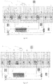
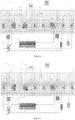
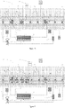
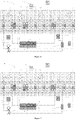
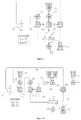
- the system needs three chambers (501, 502, 503).
- the second chamber (502), also called the distribution chamber, makes it possible to direct the dialysate towards the filter (513), the first chamber (501) to carry out a pre-dilution and/or the second chamber (502) to carry out a post dilution.
- the first and third chambers (501, 503) can also be called connecting chamber.
- the first and third chambers (501, 503) allow dialysate to be mixed with blood, ie,
- the first and third chambers (501, 503) allow fluid from the third fluid path to flow into the second fluid path.
- the channels that connect the chambers to each other or to the filter may include valves (519) and/or flow restriction or closure means (520).
- This embodiment may include at least one pressure sensor (518) - located in or near the chambers (504, 501, 502, 503), the filter (513) and/or the supply means (515, 516, 514 ) - and/or an additional pump (511) (in place of the flow restrictor (520)) in the third fluid path between the distribution chamber (502) and the connection chamber (501).
- the system may further comprise a calibration system which may comprise a sensor common to the first and third fluidic paths.
- This calibration system includes two additional channels that allow fluids in the first and third fluid paths to flow to a sixth chamber (506).
- This sixth chamber (506) comprises in or connected to it a sensor allowing the calibration of elements (sensors and/or pump) of the first and third chamber so that it is calibrated identically.
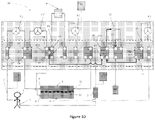
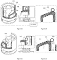
- the figure 30 discloses a processing system as previously described.
- the system further includes a cassette (601) for providing fluid dispensing functions.
- This cassette (601) is connected to reservoirs (603, 604) and cooperates with a device (602).
- the device (602) called a dialysis machine can be reusable while the cassette (601) can be disposable.
- the device (602) may include a processor (605), at least one sensor (606) adapted to cooperate with the cassette (601), at least one actuator (607) (for example pump or control means) adapted to cooperate with the cassette (601), a screen (608), at least one means acquisition and/or other such as a battery (609) and/or a memory (610).
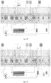
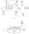
- the present document discloses a system (14) which makes it possible to carry out a treatment of the blood of a patient and which comprises a means for filtering the blood (3), at least one means for supplying liquid (F1), two patient pipes, an outlet pipe (5) taking the blood to be treated and an inlet pipe (6) reinjecting the treated blood into said patient, a filtrate recovery means (F4), at least three fluid pumps (P1, P2, P3), a cassette (2, 2') composed of channels and valves so as to direct the fluids.
- Said cassette (2, 2') comprises at least one distribution chamber (C1, C1.2, C7) comprising a single input channel and at least two output channels.
- Said treatment system (14) comprises a controller which controls the opening and closing of said valves according to the desired treatment.
- Said treatment system (14) further comprising a first fluidic path, connecting said blood filtration means (3) to the filtrate recovery means (F4), composed of a series of channels and a dedicated pump (P3 ); a second fluid path dedicated to blood circulation, comprising a series of channels, said blood filtration means (3), said patient hoses (5, 6) and a dedicated pump (P1); a third fluid path composed of a liquid supply means (F1), at least one dedicated pump (P2), a series of channels, a heating means (4) and at least a distribution chamber (C1, C1.2).
- Said cassette may further comprise at least one flow control means designed to control the amount of liquid from the third fluidic path which flows into at least one of said outlet channels of said distribution chamber (C1). Furthermore, said at least one flow regulation means is controlled by said controller which may include the processor (605).
- Said cassette (2') can also contain the pumps and/or other elements.
- the treatment system further comprises, in the third fluid path, a flow adjustment means (13, P2') located between said distribution chamber (C1) and said first connection chamber (C2).
- the third fluidic path comprises an additional pump (P2') in the third fluidic path, located between the distribution chamber (C1) and the said first connection chamber (C2).
- Said additional pump (P2') plays the total or partial role of flow adjustment means.
- the purpose of the flow adjustment means is to control the flow of fluid passing from the distribution chamber (C1) to the connection chamber (C2).
- the adjustment means thus makes it possible to distribute the quantity of fluid in the connection chamber (C2) and at least one other connection chamber or the blood filtration means (3).
- one or more flow adjustment means may be placed between any chamber or element (e.g. filter means blood (3)).
- a flow adjustment means (13) can be a pump, a proportional valve and/or a set of dedicated valve channels of different diameters, ...
- An additional safety valve can be added upstream or downstream of the means flow adjustment (13 - 520).
- a flow adjustment means allows a flow of 0% to 100% of the fluid at a given moment or during a given duration through said flow means. In other words, the flow of a fluid coming from at least one liquid supply means can be distributed in the different channels according to the needs of the treatment.
- the treatment system (14) comprises a second liquid supply means (F2 - 515) located on the patient outlet pipe (5) or in the cassette (2, 2' - 601).
- Said second supply means may contain an anticoagulant such as citrate, heparin, danaparoid sodium or the like.
- said system (14) comprises a third liquid supply means (F3 - 516) located on the patient's inlet pipe (6) or in the cassette (2, 2' - 601).
- Said liquid supply means may contain calcium or an anticoagulant inhibiting agent.
- the system comprises at least one safety element (7) making it possible to detect air bubbles in the second fluid path and/or stopping the circulation of blood and/or a means of capturing said air bubbles.
- the fluid delivery system may include a precision pump (702), a fluid supply means , a flexible bag (703) and an additional distribution pump (707).
- the system further comprises a main fluidic path (701) which is divided into at least two secondary and distinct fluidic paths (704, 704').
- the precision pump (702) and the flexible bag (703) are positioned in the main fluid path (701), the flexible bag being positioned downstream of said pump.
- the additional pump (707) is positioned in one of the secondary fluid paths (704).
- the other secondary fluid path (704') may include a valve (705).
- at least one fluid path includes a pressure sensor (706) positioned downstream of the precision pump (702). Said pressure sensor (706) can be positioned in the secondary fluid path (704) which includes the additional pump (707) and upstream of the additional pump.
- the flexible bag (703) can be a heating means.
- the heating means (4) can be located at different places of the third fluid path.
- the cassette has a heating means (4) inside the distribution chamber (C1) or upstream of the latter.
- the heating means (4) is a flexible pocket, located between the main pump (P2) of said third fluid path and said distribution chamber (C1) which makes it possible to create a constant positive pressure in said pocket (4).
- the heating pocket is continuously supplied by the pump (P2) which makes it possible, among other things, to guarantee good control of the heating of the liquid of the third fluid path.
- Said bag (4) is then directly connected to the inlet channel (V9) of the distribution chamber (C1).
- the cassette can comprise a connection chamber allowing the intersection of said two fluidic paths.
- the processing system may include peristaltic pumps. This type of pump may experience some inaccuracy.
- the dispensing system comprises at least two volume sensors for measuring the volumes of the third and first fluid paths.
- the first sensor (15) is included in the third fluid path between the distribution chamber (C1) and the main pump (P2) and measures the injected volume coming from the first liquid supply means (F1, F1').
- the sensor (15) can be located after the heating means (4).
- the second sensor (17) is placed in the first fluid path downstream of the pump and before any other chamber. Said second sensor (17) measures the volume of filtrate withdrawn. To avoid any risk of contamination, the two sensors can be located in the cassette.
- said third sensor can be located in the cassette.
- the first and second sensors (15, 17) are adjusted to a common sensor called the reference sensor (16) for optimum relative precision. Said sensors, even inaccurate, are sufficiently effective since they are accurate in comparison (relative) with respect to the reference sensor (16).
- Said reference sensor (16) may be a scale, a volumetric pump, a mass flow sensor or any sensor making it possible to measure or deduce a volume.
- Said first and second sensors (15, 17) can continuously measure liquids passing through the third and first fluid paths respectively. Thanks to the continuous measurement of the volumes, the compensation of a possible drift is possible.
- the present document discloses a fluid distribution system (100) (for example a cassette as described previously) which makes it possible to withdraw and/or deliver a fluid FI1 from and/or to the patient and to measure the pressure of said fluid FI1 .
- the system comprises a rigid body (105) composed of at least one fluid path (103) through which said FI1 fluid flows and at least one channel (102). Said channel (102) is separate from the fluidic path (103) and makes it possible to connect said fluidic path to a measurement zone (101).
- the system further comprises at least one opening (106) covered by a flexible membrane (104) forming said measurement zone.
- the membrane is shaped to receive a pressure sensor (107).
- a fluid FI2 different from the fluid FI1 is contained in said measurement zone (101).
- the FI2 fluid extends at least partially into said channel (102).
- Said fluid FI2 makes it possible to transmit by contact the pressure of fluid FI1 to said membrane (104).
- Said channel (102) is a flow restrictor shaped so that said FI1 fluid cannot come into contact with said membrane.
- the length and/or the shape of said pressure transmission channel (102) depends on the expansion capacity of said fluid FI2 and/or on the pressure range to be measured.
- the channel (102) may comprise at least one section narrow enough to retain the FI1 fluid so that said fluid does not enter said measurement zone (101).
- the channel (102) includes a hydrophobic filter (108) or membrane.
- a membrane (104) / fluid (FI3) / sensor cell (107) interface is created so as not to have friction of the membrane (104) on said cell which could create disturbances on the measurement.
- a liquid (FI1)/fluid (FI2)/membrane (104) interface is created to prevent the membrane (104) from being wetted by the liquid (FI1).
- the transmission of the pressures of FI1 is ensured by the fluids FI2 and FI3, arranged on each side of the membrane (104).
- FI2 and FI3 can be the same physical properties.
- FI2 and FI3 can be air.
- Said membrane (104) can deform with equivalent stresses on each side of these faces and this to compensate for the variations in volume of air, trapped between the membrane (104) and the sensor (107), due to the temperature.
- the fluid FI1 is of aqueous nature whereas FI2 is of lipidic nature, FI3 being able to be of lipidic or aqueous nature.
- the picture 13' discloses a fluid delivery system (100) which allows the flow of an FI1 fluid and to measure the pressure of said FI1 fluid.
- the system comprises a rigid body (105) composed of at least one fluid path (103) through which said FI1 fluid flows and at least one channel (102).
- the channel (102) is separate from the fluid path (103) but communicates so that FI1 fluid can flow through the channel (102).
- the channel (102) makes it possible to connect said fluidic path to a measurement zone (101).
- the system further comprises at least one opening (106) covered by a flexible membrane (104) forming said measurement zone. Said opening (106) can be of equal or different size from the size of the channel (102). Further, the membrane is shaped to receive a pressure sensor (107).
- a fluid FI2 different from the fluid FI1 is contained in said measurement zone (101).
- the fluid FI2 is contained at least in part in the measurement zone and/or in the channel (102).
- the quantity and/or the volume of the fluid FI2 is constant or can decrease over time so that the fluid FI1 progresses more or less rapidly in the channel (102) and/or the measurement zone (101).
- the measurement zone (101) and/or the channel (102) contain at least partially the fluid FI2 and the fluid FI1.
- the FI1 fluid may partially wet or be in contact with the membrane (104).
- the length and/or the shape of said pressure transmission channel (102) depends on the expansion capacity of said fluid FI2 and/or on the pressure range to be measured.
- the channel (102) can be shaped so as to limit and/or slow down the progression of the FI1 fluid, for example during the use of said system.
- the fluid distribution system (100) can be adapted to ensure that the membrane (104) and/or the measurement zone (101) are not fully wetted by or in contact with the FI1 fluid during the use of this system.
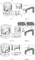
- a linear actuator (200) using a motor (for example a direct current motor (also called DC motor) or another type of motor known to those skilled in the art) (201) coupled to interposed means making it possible to transform the rotation of the motor axis into a linear movement.
- the motor may also include a torque reducer.
- Said ramp (214) comprises at least one threshold, one threshold (215) of which is located at the top of said ramp (214).
- the threshold is shaped so as to cooperate with the bearing means.
- the threshold can be perfectly flat, horizontal with respect to the vertical movement of the piston.
- the threshold can also have a specific shape to ensure good support of the support means in order to guarantee the maintenance of the position, for example, the right embodiment of the picture 18' .
- the threshold (215) located at the top of said ramp (214) is followed by a passage (219) allowing the piston (207) to free itself from the stresses exerted by said support means (209).
- the piston may include one or more ramps and/or one or more passages. At least one ramp can have an inclination between 0 and 90°. In one embodiment, said inclination may be between 0 and 45°, between 10 and 30°.
- the ramp is followed by at least one passage, for example after a threshold.
- said actuator further comprises at least one compression means (205) which exerts a force against the piston (207).
- the support means and the ramp cooperate in order to move the piston along the same axis as the force exerted by the compression means but in the opposite direction.
- said compression means tends to push the piston (relative to the actuator) (that is to say in the direction (220) of the distal end of the piston (217)) while the support means and the ramp force the piston to move closer to the actuator.
- said compression means tends to bring the piston closer of the actuator while the support means and the ramp force the piston to move away from the actuator. In this case, A ⁇ B.
- the purpose of the actuator is to drive an element of a device as described in this document. It may for example be a valve of the cassette. The remainder of the description describes this embodiment.
- the piston has a third position, where the pin (211) of the piston (207) is decoupled from the valve (212).
- a compression means (205 exerts a force against the piston, moving said piston to a third position farther from the engine than the first and second position. It can be the same compression means described above or a compression means
- d2 is equal to C.
- the interest of this third position is to guarantee sufficient occlusion pressure when the piston is coupled to the valve in the first position. otherwise, when the piston is coupled to the valve, the piston exerts a force against the valve to cause the valve to close when the piston is in the first position.
- the actuator comprises an element for fixing to its support comprising a compression means exerting a force in the direction of the distal end of the piston and having the same function described above.
- Said compression means (205) can be a spring, an elastic blade, a rubber band or a shape memory material. Said compression means (205) can exert a force of 0 to 6N, for example between 5 and 6N.
- the actuator (200) is designed with the aim of not consuming energy when maintaining a stationary position.
- the bearing means (209) is adapted to slide or roll on the ramp to reach a position.
- said threshold is shaped so that the assembly is in equilibrium.
- the threshold (215) at the top of the ramp (214) is directly followed by a passage (219) allowing the piston to pass quickly from a second position to a first position while consuming a minimum of energy.
- Said passage makes it possible to pass from one position to the other with a small amount of energy. In other words, the energy consumed by the actuator to pass from the first position to the second position is greater than the energy consumed by the actuator to pass from the second position to the first position.
- the passage (219) can be a ramp having a high slope and/or in the opposite direction to the slope of the ramp. Thus, the support means travels a shorter distance to pass from the second position to the first than vice versa.
- the piston (207) comprises several thresholds in order to have intermediate rest positions.
- the motor comprises a torque reducer between the motor and the rotor of the interposed means.
- Said torque reducer can be designed so that the motor can rotate the rotor but the rotor cannot rotate the motor.
- the torque reducer can, thanks to its design, prevent or limit or slow down any movement of the rotor which would not be caused by the motor.
- the torque reducer can be designed so that the actuator can maintain any position when the motor is stationary (powered or not).
- the actuator can comprise a limited number of thresholds as described previously but an unlimited number of positions which can be maintained thanks to the torque reducer without the actuator being supplied with current.
- Such an actuator can be adapted to cooperate with a proportional valve of a fluid distribution cassette.
- the actuator can allow the flow of a fluid in proportion to the need for the treatment.
- the piston (207) may not include a threshold but only maintainable positions thanks to the torque reducer as described above.
- This piston thus comprises at least one ramp and optionally one passage.
- the torque reducer allows the actuator to maintain a given position allowing the opening from 0% to 100% of a valve (for example a proportional valve).
- the piston includes at least one lower ramp and one upper ramp. Said ramps being adapted so that at least one support means (209) can move between said ramps. Said ramps can at least partly be parallel to each other.
- At least one actuator is included in an actuation system that includes a controller and at least one power supply means.
- Said system is designed to move at least one piston from a second position to a first position and vice versa while consuming a small amount of energy.
- Said energy supply means can be an external power supply and/or an energy storage means. Said energy storage means can be used by the system when said external power supply is no longer operational or insufficient.
- said energy storage means which may be a supercapacitor or a battery.
- the piston (207) and the rigid casing (202) comprise guide means (203, 216) in order to prevent the piston from rotating with the rotor (208) of the motor.
- a control system (800) comprises a linear actuator comprising a movable part (801) and a fixed part (804) as well as control and command elements (802, 803, 805).
- the control and command elements are suitable for knowing the position of the mobile part (801) relative to the fixed part (804) and for controlling the linear actuator.
- the figure 32 exposes the actuator in a position A and the picture 32' exposes the actuator in a position B.
- the control element (805) controls the actuator, the fixed part (804) of which may comprise the drive means (for example a motor).
- the mobile part (801) can be adapted to cooperate with, for example, a valve of a fluid distribution system.
- position A could correspond to the closed position of the valve to be controlled and position B could correspond to the open position of said valve,
- the elements 1 (802) and 2 (803) of the sensor are designed to cooperate and determine at least one position. It can be a capacitive or inductive displacement sensor (LVDT, etc.), an electromagnetic sensor (hall effect sensor), ultrasonic, infrared, optical, laser, mechanical or microwave sensor (non-exhaustive list ).
- LVDT capacitive or inductive displacement sensor
- element 1 (802) is a permanent magnet (in this case, it is not connected to the processor) (805)
- element 2 (803) is a hall effect sensor connected to the processor.
- the permanent magnet creates an electromagnetic field whose intensity the sensor (803) measures.
- the sensor (803) makes it possible to detect the variation of the magnetic field induced by the permanent magnet (802) when it moves.
- the permanent magnet (802) can be rigidly fixed permanently to the movable part (801) of the actuator and the sensor (803) is rigidly fixed permanently to the fixed part (8004) of the actuator (or Conversely).
- the permanent magnet (802) approaches or moves away from the sensor (803) which thus measures a variation in the intensity of the magnetic field of the permanent magnet (802).
- the magnet and the sensor are aligned.
- the measurement data from the sensor (802) is transmitted to the processor to process the signal.
- all control systems must be qualified in order to determine in advance the intensity corresponding to each position.
- the sensor detects predetermined value thresholds corresponding to respective positions determined in advance.
- this qualification work for example calibration which must be performed at all actuators
- this document discloses the use of a processor which performs signal processing to determine at least one position of the actuator. Thus, this makes it possible, for example, not to carry out a calibration.
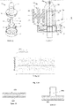
- the upper graph of the figure 33 makes it possible to highlight that the absolute value (the intensity of the electromagnetic field of the magnet measured by the sensor) can be very different from one actuator to another. Indeed, the sensors of actuators 1 and 2 do not detect the same intensity (in absolute value) although their position is identical. Thus, it would be difficult and unreliable or even impossible to determine the position of these actuators according to a single threshold value.
- the control system (800) includes a processor (805) that uses a mathematical model taking into account the derivative of the absolute value.
- the absolute value is the value measured by the sensor (803), it corresponds to the intensity of the magnetic field.
- the absolute value curve is represented by the upper graph of the figure 33 .
- the derivative of the absolute value is the leading coefficient of the curve drawn by the absolute value.
- the derivative makes it possible to know the slope of the variation of the magnetic field when the magnet moves relative to the sensor.
- This derivative is represented by the curve of the graph in the middle of the figure 33 .
- this derivative makes it possible to know the direction of the displacement of the movable part (801) of the actuator with respect to its fixed part (804).
- the control system thus comprises a processor using a mathematical model which takes account of the derivative of the signal. Thanks to this mathematical model, it is possible to know when the actuator has reached a position or a threshold as described in the chapter disclosing the linear actuator. Indeed, when the actuator moves its mobile part (801) the first derivative is greater or less than 0 but when the actuator does not move its mobile part (801), its first derivative is substantially equal to 0. In our example , when the magnet (802) moves away from the sensor (803) the first derivative is negative and conversely when the magnet approaches, the first derivative is positive.
- the system may further include a mathematical model to determine when the moving part moves and when it remains stationary.
- This second mathematical model takes into account the second derivative of the absolute value. Thanks to this second model mathematical, the system knows when the mobile part changes its behavior (mobile or stationary).
- control system includes an actuator comprising at least one ramp and at least one threshold (eg, a linear actuator as described herein), a processor adapted to control the actuator and to process the signal according to at least one mathematical model.
- actuator comprising at least one ramp and at least one threshold (eg, a linear actuator as described herein)
- processor adapted to control the actuator and to process the signal according to at least one mathematical model.
- a first mathematical model takes into account the first derivative of the absolute value measured by the sensor (803).
- the processor can use this first mathematical model in order to know in which direction the mobile part (801) moves.
- the control system knows that the actuator has reached a threshold.
- a second mathematical model takes into account the second derivative of the absolute value measured by the sensor (803).
- the processor can use the second mathematical model in order to know when a threshold is reached and/or when the moving part is stationary or moving.
- the lower graph of the figure 33 represents the signal resulting from the second mathematical model.
- the signal is equal to the value f, this means that the actuator maintains a position or is on a threshold.
- the signal is equal to the value d, means that the mobile part (801) moves.
- the system does not need the absolute value.
- the control system supplies the actuator to move its mobile part (801)
- the second mathematical model makes it possible to know when the actuator has reached a position.
- the processor when the actuator continues its actuation (for example, it rotates the support means (209)) but the moving part no longer moves, thanks to the first and/or second derivative, the processor is capable of know that the means of support has reached a threshold.
- the processor orders the actuator to change position, a mathematical model allows the processor to know when the threshold has been reached and thus orders the actuator to stop.
- said control system is suitable for determining at least one position reached by the moving part (801) of the actuator independently of the characteristics of the sensor used.
- Said control system is suitable for controlling the stoppage of the actuator at at least one position reached by the moving part (801) of the actuator independently of the characteristics of the sensor used.
- the control system comprises an actuator comprising at least two distinct positions.
- the actuator comprises at least one threshold defining a position and at least one ramp making it possible to change position.
- the actuator is driven by a motor designed to rotate for example in one direction only so that it moves from one position to another sequentially and in a pre-established order.
- the actuator can be adapted to return to its starting position by carrying out at least a partial revolution.
- the processor includes a mathematical model which takes account of the second derivative of the absolute value measured by said sensor.
- Said processor comprises a memory which contains the sequence of positions so that said system does not need to know the first derivative of the absolute value to know the position of the actuator. It suffices for the actuator to perform one revolution to know its position precisely, for example, when starting up the system.
- the treatment system may include a drive device used for peristaltic pumps.
- Said driving device disclosed herein can also be used by various peristaltic pumps and/or fluid delivery systems comprising a peristaltic pump.
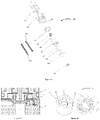
- a drive device which comprises a floating shaft (301) driven by a drive means (303) fixed to a rotor (310) of an electric motor (not shown).
- Said floating shaft (301) comprises an integral base (311)/cover (302) assembly containing a cavity inside which said drive means (303) is at least partially circumscribed.
- Said driving means (303) comprises a rigid body shaped so as to cooperate with the walls (309, 309') of said cavity (313) in order to allow a restricted freedom of the floating axis (301) with respect to the axis of said rotor (310).
- a screw (307) can make it possible to fix the drive means (303) to said rotor (310).
- the cavity comprises at least one cooperation element (312) which allows said drive means (303) to transmit a rotational movement to said floating axis.
- Said cooperating element (312) may be an opening bounded by two hard elements (308) and through which an axis (306) is housed perpendicularly. The space between the two hard elements (308) is reasonably greater than the diameter of the axis (306).
- the hard elements (308) and/or the axis (306) can be made from hard metals such as cobalt, tungsten, vanadium, chromium, manganese, nickel, titanium, germanium, gallium, bismuth, iridium, lithium, magnesium , molybdenum, strontium, rubidium or palladium.
- the hard elements (308) have a greater hardness than the shaft (306).
- the hard elements (308) and/or the pin (306) can receive a treatment to increase their hardness, for example zirconium oxide or one of its alloys.
- the body (304) of said drive means (303) may be perfectly round or partially flattened spherical in shape.
- said body (304) forms a roller comprising three faces. Two of the three faces oppose each other and are interconnected via the third face which is curved. According to the X-Z plane, said roller forms a circle formed by said curved face. The connection between at least one of the two faces which oppose the curved face can be rounded along the X-Y plane.
- the opposing faces can be substantially planar and/or substantially parallel to each other.
- the cavity (313) includes smooth walls (309, 309').
- the upper wall (309) and/or the lower wall (309') of said cavity (313) may be of at least partially conical shape.
- the surfaces of the top (309) and bottom (309') walls can be flat or curved.
- the cone of the smooth wall (309) is defined according to an angle comprised between 0 and 90°, for example between 5 and 30°.
- the cone of the opposite smooth wall (309') is defined according to an angle between -0 and -90°, for example between -5 and -30°.
- the angles of the two partial cones can be equal or different.
- the smooth walls (309, 309') are adapted to cooperate with the ends of the body (304) so that the floating axis (301) can move along at least the three axes X, Y or Z and/or undergo pitching movements. For example, along the Y axis, the floating axis (301) can undergo a pitch movement of +/- 10°, for example less than +/- 5°.
- the drive means (303) comprises a longitudinal axis (305) and the floating axis (301) comprises a second cavity (313') which is extends along the floating axis.
- the longitudinal axis (305) is inserted inside the second cavity (313') in order to restrict the pitching movements of the floating axis (301).
- the dimensions of the elements forming the drive means (303, 306, 305) are reasonably smaller than the elements forming the inside of the floating shaft (301, 302, 313, 312).
- the drive system (300) includes a one piece drive shaft which extends along the Y axis and which is adapted to drive at least one roller (320) of a peristaltic pump system. Said roller is suitable for crushing a flexible tube (not shown) against a wall (not shown).
- the drive axis is represented by the floating axis (301).
- the drive shaft can be the floating shaft and/or merged with part of the drive system.
- the drive shaft can be cylindrical in shape and include a bevelled free end (here the term free end is opposed to the opposite end which is linked directly or indirectly to the motor).
- the drive shaft cylinder forms a circle along an XZ plane.
- said drive shaft is formed from a single piece composed of at least two different cylinders defined by the same axis (in other words the center of the cylinder) but having different diameters.
- the drive axis can form at least two parallel circles but of different sizes.
- the drive shaft may comprise three cylinders of which only one is of different diameter.
- the cylinder defined by the smaller diameter can be arranged between the two cylinders of equal diameter.
- Said larger diameter cylinders may have surfaces treated so as to improve cooperation with the rollers of the peristaltic pump.
- This construction of the three-cylinder drive shaft is particularly suitable and advantageous for the use of an H-shaped roller, such as the roller (320) of the figure 23 .
- the roller is included in a peristaltic pump system and crushes a flexible pipe.
- the crushing function can be performed by a rigid part (322) of the roller (320).
- Said roller (320) is a cylinder forming a circle on the XZ plane and comprises an axis (321) at the center of this cylinder which extends along the Y axis, a rigid part (322) and at least one flexible part (323) which is deformable.
- the flexible part is adapted to cooperate with the drive shaft.
- the larger diameter cylinders can come into contact with the flexible parts (323) of the roller (320) and cause the roller (320).
- said flexible part (323) can deform in order to improve the cooperation between these two elements and/or to adjust the tolerance errors of each of the elements.
- the roller can comprise a rigid part (322) in its center and two flexible parts (323) at the ends along the Y axis.
- a fluid distribution system comprising a floating shaft (301), a three-cylinder drive shaft and/or a roller with rigid and flexible parts makes it possible to substantially improve the roller / drive shaft cooperation and to correct errors tolerance of the various elements of the system.
- the treatment system comprises at least one means for damping the pressure peaks.
- the figure 24 shows the pressure signal measured near the inlet of a peristaltic pump.
- the first curve (401) it is possible to observe the oscillation of the pressure while the second curve (402) represents the mean value of this pressure.
- the purpose of the damper is to reduce the amplitude of the oscillations of the first curve (401).
- damping means can be installed in one or more fluid paths of a distribution system as described above. This damping means can be integrated into a cassette.
- each treatment has one or more possible configurations.
- the phenomenon of pressure peaks can be amplified or attenuated by various elements which vary according to said configurations. Reproducibility is thus an important element because the operator (generally the nurse) must be able to ensure the correct operation of the system without being obliged to take into account the characteristics of the various elements.
- the delivery system as disclosed herein may be a cassette through which fluids flow in three fluid paths. These fluids can be propelled by peristaltic pumps. Reproducibility, accuracy and patient comfort are important.
- at least one damping means can be integrated into said cassette. To be as effective as possible, said damping means must be placed as close as possible to the pumping system.
- the fluidic path comprises walls (404) delimiting said path. These walls can be the rigid walls of the cassette.
- a section of the fluid path is covered with a flexible membrane (403) which then replaces said wall (404). Thanks to the elasticity of said flexible membrane (403), the pressure peaks are substantially attenuated, absorbed by the deformation of the membrane (403). The absorption of these peaks is a function of the size and the elastic characteristics of the membrane.
- the fluidic path also comprises walls delimiting said path but one section is replaced by a cavity filled with a compressible fluid such as air.
- a compressible fluid such as air.
- This air may have been trapped (about 1mL) when priming the system.
- the air volume is more or less compressed during the pumping, absorbing the energy of the pressure peaks.
- This embodiment is particularly effective because it requires little energy for its operation and said fluid absorbs pressure peaks very quickly.
- the cavity or the entrance to the cavity can be designed to prevent the compressible fluid from completely escaping. In other words, the cavity can be designed to prevent the flowing fluid from replacing the compressible fluid.
- Said damping means can be placed upstream of the pumping mechanism.
Landscapes
- Health & Medical Sciences (AREA)
- Heart & Thoracic Surgery (AREA)
- Engineering & Computer Science (AREA)
- Vascular Medicine (AREA)
- Animal Behavior & Ethology (AREA)
- Veterinary Medicine (AREA)
- Anesthesiology (AREA)
- Biomedical Technology (AREA)
- Hematology (AREA)
- Life Sciences & Earth Sciences (AREA)
- Public Health (AREA)
- General Health & Medical Sciences (AREA)
- Urology & Nephrology (AREA)
- Cardiology (AREA)
- Emergency Medicine (AREA)
- Mechanical Engineering (AREA)
- General Engineering & Computer Science (AREA)
- External Artificial Organs (AREA)
- Physics & Mathematics (AREA)
- Fluid Mechanics (AREA)
- Connection Of Motors, Electrical Generators, Mechanical Devices, And The Like (AREA)
- Medicines Containing Material From Animals Or Micro-Organisms (AREA)
Priority Applications (1)
| Application Number | Priority Date | Filing Date | Title |
|---|---|---|---|
| EP22186084.4A EP4098290B1 (fr) | 2012-10-29 | 2013-10-29 | Dispositif de traitement extra corporel du sang |
Applications Claiming Priority (2)
| Application Number | Priority Date | Filing Date | Title |
|---|---|---|---|
| PCT/IB2012/055972 WO2014076519A1 (fr) | 2012-10-29 | 2012-10-29 | Dispositif de traitement extra corporel du sang |
| PCT/IB2013/059744 WO2014068475A2 (fr) | 2012-10-29 | 2013-10-29 | Dispositif de traitement extra corporel du sang |
Related Child Applications (2)
| Application Number | Title | Priority Date | Filing Date |
|---|---|---|---|
| EP22186084.4A Division EP4098290B1 (fr) | 2012-10-29 | 2013-10-29 | Dispositif de traitement extra corporel du sang |
| EP22186084.4A Division-Into EP4098290B1 (fr) | 2012-10-29 | 2013-10-29 | Dispositif de traitement extra corporel du sang |
Publications (2)
| Publication Number | Publication Date |
|---|---|
| EP2911716A2 EP2911716A2 (fr) | 2015-09-02 |
| EP2911716B1 true EP2911716B1 (fr) | 2022-08-31 |
Family
ID=47351883
Family Applications (2)
| Application Number | Title | Priority Date | Filing Date |
|---|---|---|---|
| EP13821164.4A Active EP2911716B1 (fr) | 2012-10-29 | 2013-10-29 | Dispositif de traitement extra corporel du sang |
| EP22186084.4A Active EP4098290B1 (fr) | 2012-10-29 | 2013-10-29 | Dispositif de traitement extra corporel du sang |
Family Applications After (1)
| Application Number | Title | Priority Date | Filing Date |
|---|---|---|---|
| EP22186084.4A Active EP4098290B1 (fr) | 2012-10-29 | 2013-10-29 | Dispositif de traitement extra corporel du sang |
Country Status (15)
| Country | Link |
|---|---|
| US (3) | US10138911B2 (enExample) |
| EP (2) | EP2911716B1 (enExample) |
| JP (2) | JP6440621B2 (enExample) |
| KR (1) | KR102223729B1 (enExample) |
| CN (2) | CN104884102B (enExample) |
| AU (2) | AU2013340390B2 (enExample) |
| BR (1) | BR112015009503B1 (enExample) |
| CA (1) | CA2889362C (enExample) |
| ES (2) | ES3056556T3 (enExample) |
| MX (1) | MX365602B (enExample) |
| MY (1) | MY174010A (enExample) |
| PH (1) | PH12015500954B1 (enExample) |
| PT (1) | PT2911716T (enExample) |
| RU (1) | RU2648223C2 (enExample) |
| WO (2) | WO2014076519A1 (enExample) |
Families Citing this family (19)
| Publication number | Priority date | Publication date | Assignee | Title |
|---|---|---|---|---|
| WO2014076519A1 (fr) | 2012-10-29 | 2014-05-22 | Debiotech S.A. | Dispositif de traitement extra corporel du sang |
| EP3031485B1 (en) * | 2014-12-10 | 2018-11-21 | B. Braun Avitum AG | Method and control apparatus for determining and adjusting a flow rate of a blood delivery pump |
| UA122139C2 (uk) * | 2014-12-23 | 2020-09-25 | Деррік Корпорейшн | Системи, пристрої та способи для кріплення вузлів сита |
| AU2016363021A1 (en) * | 2015-12-04 | 2018-05-31 | Qidni Labs, Inc. | An implantable renal replacement therapy |
| US10994064B2 (en) | 2016-08-10 | 2021-05-04 | Medtronic, Inc. | Peritoneal dialysate flow path sensing |
| US10874790B2 (en) | 2016-08-10 | 2020-12-29 | Medtronic, Inc. | Peritoneal dialysis intracycle osmotic agent adjustment |
| EP3439711A1 (en) | 2016-04-04 | 2019-02-13 | Medtronic Inc. | Peritoneal dialysate fluid generation system |
| US12329892B2 (en) | 2016-04-04 | 2025-06-17 | Mozarc Medical Us Llc | Dextrose concentration sensor for a peritoneal dialysis system |
| GB2562519B (en) * | 2017-05-18 | 2019-11-13 | Keymed Medical & Ind Equipment Ltd | Peristaltic pump |
| US11806457B2 (en) | 2018-11-16 | 2023-11-07 | Mozarc Medical Us Llc | Peritoneal dialysis adequacy meaurements |
| US11806456B2 (en) | 2018-12-10 | 2023-11-07 | Mozarc Medical Us Llc | Precision peritoneal dialysis therapy based on dialysis adequacy measurements |
| JP2022539428A (ja) * | 2019-07-12 | 2022-09-08 | エッペンドルフ・ソシエタス・エウロパエア | センサ無し膜ポンプの制御配置及び制御方法 |
| EP3900754B1 (en) | 2020-04-20 | 2024-10-02 | Gambro Lundia AB | Apparatus for extracorporeal blood treatment |
| IT202000030332A1 (it) | 2020-12-10 | 2022-06-10 | Baxter Int | Gruppo collettore per un apparato di dialisi peritoneale e apparato di dialisi peritoneale che comprende detto gruppo collettore |
| US11965763B2 (en) | 2021-11-12 | 2024-04-23 | Mozarc Medical Us Llc | Determining fluid flow across rotary pump |
| EP4344713A1 (en) | 2022-09-29 | 2024-04-03 | NextKidney SA | Pump monitored by sensor |
| TR2025005068A2 (tr) * | 2022-10-25 | 2025-11-21 | Derrick Corporation | Malzemelerin elenmesi için sıkıştırma aparatları, sistemleri ve usulleri |
| EP4393529A1 (en) | 2022-12-29 | 2024-07-03 | Gambro Lundia AB | Disposable set, apparatus and procedure of blood recirculation in an extracorporeal blood treatment apparatus |
| CN116570789B (zh) * | 2023-07-13 | 2023-10-13 | 四川天府南格尔生物医学有限公司 | 一种血浆采集系统及采集方法 |
Family Cites Families (45)
| Publication number | Priority date | Publication date | Assignee | Title |
|---|---|---|---|---|
| US3288115A (en) * | 1965-07-16 | 1966-11-29 | Radiant Pen Corp | Ball-point pen mechanism |
| DE1561801A1 (de) * | 1967-07-22 | 1971-01-28 | Ritter Kg J | Kugelschreibgeraet od.dgl. |
| US4747950A (en) * | 1983-12-16 | 1988-05-31 | Cd Medical, Inc. | Method and apparatus for controlled ultrafiltration during hemodialysis |
| US4976162A (en) | 1987-09-03 | 1990-12-11 | Kamen Dean L | Enhanced pressure measurement flow control system |
| US4861242A (en) * | 1987-08-19 | 1989-08-29 | Cobe Laboratories, Inc. | Self-loading peristaltic pump |
| GB2213549A (en) * | 1987-12-10 | 1989-08-16 | Kevin Wilcox | Improvements in or relating to mechanisms for translating reciprocating motion into rotary motion and vice versa |
| CN1015149B (zh) * | 1988-07-11 | 1991-12-25 | 淄博无线电五厂 | 血液灌流仪 |
| US5252044A (en) * | 1992-10-20 | 1993-10-12 | Medflow, Inc. | Parenteral fluid pump with disposable cassette |
| US5441636A (en) * | 1993-02-12 | 1995-08-15 | Cobe Laboratories, Inc. | Integrated blood treatment fluid module |
| DE69408055T2 (de) * | 1993-04-02 | 1998-05-07 | Yamaha Motor Co Ltd | Verfahren und Einrichtung zur Schmierung einer Brennkraftmaschine |
| US5447417A (en) * | 1993-08-31 | 1995-09-05 | Valleylab Inc. | Self-adjusting pump head and safety manifold cartridge for a peristaltic pump |
| US5535869A (en) * | 1993-10-26 | 1996-07-16 | Warn Industries, Inc. | Pulse actuated clutch for vehicle drive lines |
| FR2719873A1 (fr) * | 1994-05-11 | 1995-11-17 | Debiotech Sa | Dispositif de pompe péristaltique. |
| US6036459A (en) * | 1996-04-04 | 2000-03-14 | Medtronic, Inc. | Occlusion compensator for implantable peristaltic pump |
| JPH10274351A (ja) * | 1997-03-28 | 1998-10-13 | Mitsubishi Materials Corp | 弁 |
| CA2211848C (en) * | 1997-07-28 | 2002-06-11 | Joseph E. Dadson | Peritoneal dialysis apparatus |
| US6186665B1 (en) | 1999-01-26 | 2001-02-13 | Nimbus, Inc. | Motor rotor bearing assembly for a blood pump |
| US6375577B1 (en) * | 1999-10-27 | 2002-04-23 | Abbott Laboratories | Universal style coupling |
| US6364034B1 (en) * | 2000-02-08 | 2002-04-02 | William N Schoeffler | Directional drilling apparatus |
| JP3597453B2 (ja) * | 2000-09-22 | 2004-12-08 | 株式会社市丸技研 | 直動形電動バルブ |
| EP1195171B1 (en) | 2000-10-04 | 2012-08-15 | Terumo Kabushiki Kaisha | Peritoneal dialysis apparatus |
| KR100503477B1 (ko) * | 2002-12-24 | 2005-07-25 | 삼성전자주식회사 | 잉크젯 프린터의 펌프장치 |
| US7247146B2 (en) * | 2003-02-07 | 2007-07-24 | Gambro Lundia Ab | Support element for an integrated blood treatment module, integrated blood treatment module and extracorporeal blood treatment apparatus equipped with said integrated module |
| US7018182B2 (en) * | 2003-03-13 | 2006-03-28 | Chf Solutions, Inc. | Self-loading peristaltic pump for extracorporeal blood circuit |
| US7318539B2 (en) * | 2003-04-28 | 2008-01-15 | Power Sprayer Llc | Pump drive unit for battery operated fluid dispensers |
| US8585634B2 (en) | 2003-07-31 | 2013-11-19 | Debiotech S.A. | System for performing peritoneal dialysis |
| GB2404695B (en) * | 2003-08-04 | 2006-05-31 | Itt Mfg Enterprises Inc | Self-priming centrifugal pump |
| US8029454B2 (en) * | 2003-11-05 | 2011-10-04 | Baxter International Inc. | High convection home hemodialysis/hemofiltration and sorbent system |
| US20050209563A1 (en) * | 2004-03-19 | 2005-09-22 | Peter Hopping | Cassette-based dialysis medical fluid therapy systems, apparatuses and methods |
| US7104523B2 (en) * | 2004-06-12 | 2006-09-12 | Borgwarner Inc. | Valve having contamination counter-measures |
| US7555977B2 (en) * | 2005-09-23 | 2009-07-07 | Bae Systems Land & Armaments L.P. | Firing pin and valve assembly |
| US20070258838A1 (en) * | 2006-05-03 | 2007-11-08 | Sherwood Services Ag | Peristaltic cooling pump system |
| FR2914975B1 (fr) * | 2007-04-16 | 2009-05-29 | Valeo Sys Controle Moteur Sas | Dispositif de transformation d'un mouvement de pivotement d'un pignon en un mouvement de translation d'un coulisseau et vanne comportant un tel dispositif |
| ITBO20070777A1 (it) * | 2007-11-23 | 2009-05-24 | Tema Sinergie S R L | Dispositivo di calibrazione per macchine dosatrici di sostanze radioattive. |
| US7771392B2 (en) * | 2007-11-29 | 2010-08-10 | Roche Diagnostics Operations, Inc. | Lead screw delivery device using reusable shape memory actuator drive |
| TWI361856B (en) * | 2008-11-04 | 2012-04-11 | Ind Tech Res Inst | Multi-cam electric valve mechanism for engine |
| US9133674B2 (en) * | 2009-02-24 | 2015-09-15 | Schlumberger Technology Corporation | Downhole tool actuation having a seat with a fluid by-pass |
| ES2403598T5 (es) * | 2009-12-22 | 2016-12-13 | Gambro Lundia Ab | Método y aparato para controlar una velocidad de flujo de fluido en un conducto de transporte de fluido de un dispositivo médico |
| ES2625878T3 (es) | 2010-10-29 | 2017-07-20 | Bellandtechnology Ag | Copolímero soluble en agua o desintegrable en agua |
| DE102011008223B4 (de) * | 2011-01-10 | 2019-07-04 | Fresenius Medical Care Deutschland Gmbh | Dialysebehandlungseinheit |
| ITMI20110442A1 (it) * | 2011-03-21 | 2012-09-22 | Gambro Lundia Ab | Apparecchiatura per il trattamento extracorporeo di sangue. |
| RU119056U1 (ru) * | 2012-04-16 | 2012-08-10 | Общество с ограниченной ответственностью "Научно-производственная фирма "БИТЕК" | Электромеханический привод запорного клапана |
| WO2014076519A1 (fr) | 2012-10-29 | 2014-05-22 | Debiotech S.A. | Dispositif de traitement extra corporel du sang |
| KR20140110496A (ko) * | 2013-03-08 | 2014-09-17 | 삼성전자주식회사 | 약물 주입 펌프 |
| RU2016119380A (ru) * | 2013-10-31 | 2017-12-05 | Свиссиннов Продакт Сарл | Портативный насос и способ его изготовления |
-
2012
- 2012-10-29 WO PCT/IB2012/055972 patent/WO2014076519A1/fr not_active Ceased
-
2013
- 2013-10-29 CN CN201380068897.5A patent/CN104884102B/zh active Active
- 2013-10-29 WO PCT/IB2013/059744 patent/WO2014068475A2/fr not_active Ceased
- 2013-10-29 CN CN201810246111.9A patent/CN108815604B/zh active Active
- 2013-10-29 AU AU2013340390A patent/AU2013340390B2/en not_active Ceased
- 2013-10-29 BR BR112015009503-8A patent/BR112015009503B1/pt not_active IP Right Cessation
- 2013-10-29 ES ES22186084T patent/ES3056556T3/es active Active
- 2013-10-29 CA CA2889362A patent/CA2889362C/fr active Active
- 2013-10-29 ES ES13821164T patent/ES2927377T3/es active Active
- 2013-10-29 RU RU2015117238A patent/RU2648223C2/ru active
- 2013-10-29 EP EP13821164.4A patent/EP2911716B1/fr active Active
- 2013-10-29 US US14/439,382 patent/US10138911B2/en active Active
- 2013-10-29 KR KR1020157014088A patent/KR102223729B1/ko not_active Expired - Fee Related
- 2013-10-29 JP JP2015538621A patent/JP6440621B2/ja active Active
- 2013-10-29 MX MX2015005116A patent/MX365602B/es active IP Right Grant
- 2013-10-29 EP EP22186084.4A patent/EP4098290B1/fr active Active
- 2013-10-29 PT PT138211644T patent/PT2911716T/pt unknown
- 2013-10-29 MY MYPI2015001117A patent/MY174010A/en unknown
-
2015
- 2015-04-29 PH PH12015500954A patent/PH12015500954B1/en unknown
-
2017
- 2017-12-19 AU AU2017279606A patent/AU2017279606B2/en not_active Ceased
-
2018
- 2018-11-19 JP JP2018216149A patent/JP6685371B2/ja active Active
- 2018-11-20 US US16/196,339 patent/US11092148B2/en active Active
-
2021
- 2021-07-13 US US17/374,856 patent/US20210340968A1/en not_active Abandoned
Also Published As
Similar Documents
| Publication | Publication Date | Title |
|---|---|---|
| EP2911716B1 (fr) | Dispositif de traitement extra corporel du sang | |
| EP2763720B1 (fr) | Machine de dialyse comprenant des moyens d'ultrafiltration et de rétrofiltration | |
| US10080831B2 (en) | Dialysis systems, components, and methods |
Legal Events
| Date | Code | Title | Description |
|---|---|---|---|
| PUAI | Public reference made under article 153(3) epc to a published international application that has entered the european phase |
Free format text: ORIGINAL CODE: 0009012 |
|
| 17P | Request for examination filed |
Effective date: 20150519 |
|
| AK | Designated contracting states |
Kind code of ref document: A2 Designated state(s): AL AT BE BG CH CY CZ DE DK EE ES FI FR GB GR HR HU IE IS IT LI LT LU LV MC MK MT NL NO PL PT RO RS SE SI SK SM TR |
|
| AX | Request for extension of the european patent |
Extension state: BA ME |
|
| DAX | Request for extension of the european patent (deleted) | ||
| STAA | Information on the status of an ep patent application or granted ep patent |
Free format text: STATUS: EXAMINATION IS IN PROGRESS |
|
| 17Q | First examination report despatched |
Effective date: 20200224 |
|
| GRAP | Despatch of communication of intention to grant a patent |
Free format text: ORIGINAL CODE: EPIDOSNIGR1 |
|
| STAA | Information on the status of an ep patent application or granted ep patent |
Free format text: STATUS: GRANT OF PATENT IS INTENDED |
|
| RIC1 | Information provided on ipc code assigned before grant |
Ipc: A61M 1/34 20060101ALI20220405BHEP Ipc: F16K 31/04 20060101ALI20220405BHEP Ipc: F16H 25/12 20060101ALI20220405BHEP Ipc: A61M 1/16 20060101ALI20220405BHEP Ipc: A61M 1/36 20060101ALI20220405BHEP Ipc: A61M 1/14 20060101AFI20220405BHEP |
|
| INTG | Intention to grant announced |
Effective date: 20220426 |
|
| RIC1 | Information provided on ipc code assigned before grant |
Ipc: F16K 31/528 20060101ALI20220408BHEP Ipc: F16K 7/16 20060101ALI20220408BHEP Ipc: A61M 1/36 20060101ALI20220408BHEP Ipc: A61M 1/16 20060101ALI20220408BHEP Ipc: F16H 25/12 20060101ALI20220408BHEP Ipc: F16K 31/04 20060101ALI20220408BHEP Ipc: A61M 1/34 20060101ALI20220408BHEP Ipc: A61M 1/14 20060101AFI20220408BHEP |
|
| GRAS | Grant fee paid |
Free format text: ORIGINAL CODE: EPIDOSNIGR3 |
|
| GRAA | (expected) grant |
Free format text: ORIGINAL CODE: 0009210 |
|
| STAA | Information on the status of an ep patent application or granted ep patent |
Free format text: STATUS: THE PATENT HAS BEEN GRANTED |
|
| AK | Designated contracting states |
Kind code of ref document: B1 Designated state(s): AL AT BE BG CH CY CZ DE DK EE ES FI FR GB GR HR HU IE IS IT LI LT LU LV MC MK MT NL NO PL PT RO RS SE SI SK SM TR |
|
| REG | Reference to a national code |
Ref country code: CH Ref legal event code: EP Ref country code: GB Ref legal event code: FG4D Free format text: NOT ENGLISH |
|
| REG | Reference to a national code |
Ref country code: AT Ref legal event code: REF Ref document number: 1514835 Country of ref document: AT Kind code of ref document: T Effective date: 20220915 Ref country code: DE Ref legal event code: R096 Ref document number: 602013082439 Country of ref document: DE |
|
| REG | Reference to a national code |
Ref country code: PT Ref legal event code: SC4A Ref document number: 2911716 Country of ref document: PT Date of ref document: 20220923 Kind code of ref document: T Free format text: AVAILABILITY OF NATIONAL TRANSLATION Effective date: 20220919 |
|
| REG | Reference to a national code |
Ref country code: IE Ref legal event code: FG4D Free format text: LANGUAGE OF EP DOCUMENT: FRENCH |
|
| REG | Reference to a national code |
Ref country code: RO Ref legal event code: EPE |
|
| REG | Reference to a national code |
Ref country code: ES Ref legal event code: FG2A Ref document number: 2927377 Country of ref document: ES Kind code of ref document: T3 Effective date: 20221104 |
|
| REG | Reference to a national code |
Ref country code: GR Ref legal event code: EP Ref document number: 20220401971 Country of ref document: GR Effective date: 20221109 |
|
| REG | Reference to a national code |
Ref country code: LT Ref legal event code: MG9D |
|
| REG | Reference to a national code |
Ref country code: NL Ref legal event code: MP Effective date: 20220831 |
|
| PG25 | Lapsed in a contracting state [announced via postgrant information from national office to epo] |
Ref country code: SE Free format text: LAPSE BECAUSE OF FAILURE TO SUBMIT A TRANSLATION OF THE DESCRIPTION OR TO PAY THE FEE WITHIN THE PRESCRIBED TIME-LIMIT Effective date: 20220831 Ref country code: RS Free format text: LAPSE BECAUSE OF FAILURE TO SUBMIT A TRANSLATION OF THE DESCRIPTION OR TO PAY THE FEE WITHIN THE PRESCRIBED TIME-LIMIT Effective date: 20220831 Ref country code: NO Free format text: LAPSE BECAUSE OF FAILURE TO SUBMIT A TRANSLATION OF THE DESCRIPTION OR TO PAY THE FEE WITHIN THE PRESCRIBED TIME-LIMIT Effective date: 20221130 Ref country code: LV Free format text: LAPSE BECAUSE OF FAILURE TO SUBMIT A TRANSLATION OF THE DESCRIPTION OR TO PAY THE FEE WITHIN THE PRESCRIBED TIME-LIMIT Effective date: 20220831 Ref country code: LT Free format text: LAPSE BECAUSE OF FAILURE TO SUBMIT A TRANSLATION OF THE DESCRIPTION OR TO PAY THE FEE WITHIN THE PRESCRIBED TIME-LIMIT Effective date: 20220831 Ref country code: FI Free format text: LAPSE BECAUSE OF FAILURE TO SUBMIT A TRANSLATION OF THE DESCRIPTION OR TO PAY THE FEE WITHIN THE PRESCRIBED TIME-LIMIT Effective date: 20220831 |
|
| REG | Reference to a national code |
Ref country code: AT Ref legal event code: MK05 Ref document number: 1514835 Country of ref document: AT Kind code of ref document: T Effective date: 20220831 |
|
| PG25 | Lapsed in a contracting state [announced via postgrant information from national office to epo] |
Ref country code: PL Free format text: LAPSE BECAUSE OF FAILURE TO SUBMIT A TRANSLATION OF THE DESCRIPTION OR TO PAY THE FEE WITHIN THE PRESCRIBED TIME-LIMIT Effective date: 20220831 Ref country code: IS Free format text: LAPSE BECAUSE OF FAILURE TO SUBMIT A TRANSLATION OF THE DESCRIPTION OR TO PAY THE FEE WITHIN THE PRESCRIBED TIME-LIMIT Effective date: 20221231 Ref country code: HR Free format text: LAPSE BECAUSE OF FAILURE TO SUBMIT A TRANSLATION OF THE DESCRIPTION OR TO PAY THE FEE WITHIN THE PRESCRIBED TIME-LIMIT Effective date: 20220831 |
|
| PG25 | Lapsed in a contracting state [announced via postgrant information from national office to epo] |
Ref country code: SM Free format text: LAPSE BECAUSE OF FAILURE TO SUBMIT A TRANSLATION OF THE DESCRIPTION OR TO PAY THE FEE WITHIN THE PRESCRIBED TIME-LIMIT Effective date: 20220831 Ref country code: DK Free format text: LAPSE BECAUSE OF FAILURE TO SUBMIT A TRANSLATION OF THE DESCRIPTION OR TO PAY THE FEE WITHIN THE PRESCRIBED TIME-LIMIT Effective date: 20220831 Ref country code: CZ Free format text: LAPSE BECAUSE OF FAILURE TO SUBMIT A TRANSLATION OF THE DESCRIPTION OR TO PAY THE FEE WITHIN THE PRESCRIBED TIME-LIMIT Effective date: 20220831 Ref country code: AT Free format text: LAPSE BECAUSE OF FAILURE TO SUBMIT A TRANSLATION OF THE DESCRIPTION OR TO PAY THE FEE WITHIN THE PRESCRIBED TIME-LIMIT Effective date: 20220831 |
|
| PG25 | Lapsed in a contracting state [announced via postgrant information from national office to epo] |
Ref country code: SK Free format text: LAPSE BECAUSE OF FAILURE TO SUBMIT A TRANSLATION OF THE DESCRIPTION OR TO PAY THE FEE WITHIN THE PRESCRIBED TIME-LIMIT Effective date: 20220831 Ref country code: MC Free format text: LAPSE BECAUSE OF FAILURE TO SUBMIT A TRANSLATION OF THE DESCRIPTION OR TO PAY THE FEE WITHIN THE PRESCRIBED TIME-LIMIT Effective date: 20220831 Ref country code: EE Free format text: LAPSE BECAUSE OF FAILURE TO SUBMIT A TRANSLATION OF THE DESCRIPTION OR TO PAY THE FEE WITHIN THE PRESCRIBED TIME-LIMIT Effective date: 20220831 |
|
| REG | Reference to a national code |
Ref country code: CH Ref legal event code: PL |
|
| REG | Reference to a national code |
Ref country code: DE Ref legal event code: R097 Ref document number: 602013082439 Country of ref document: DE |
|
| PG25 | Lapsed in a contracting state [announced via postgrant information from national office to epo] |
Ref country code: NL Free format text: LAPSE BECAUSE OF FAILURE TO SUBMIT A TRANSLATION OF THE DESCRIPTION OR TO PAY THE FEE WITHIN THE PRESCRIBED TIME-LIMIT Effective date: 20220831 Ref country code: LU Free format text: LAPSE BECAUSE OF NON-PAYMENT OF DUE FEES Effective date: 20221029 Ref country code: AL Free format text: LAPSE BECAUSE OF FAILURE TO SUBMIT A TRANSLATION OF THE DESCRIPTION OR TO PAY THE FEE WITHIN THE PRESCRIBED TIME-LIMIT Effective date: 20220831 |
|
| PLBE | No opposition filed within time limit |
Free format text: ORIGINAL CODE: 0009261 |
|
| STAA | Information on the status of an ep patent application or granted ep patent |
Free format text: STATUS: NO OPPOSITION FILED WITHIN TIME LIMIT |
|
| PG25 | Lapsed in a contracting state [announced via postgrant information from national office to epo] |
Ref country code: LI Free format text: LAPSE BECAUSE OF NON-PAYMENT OF DUE FEES Effective date: 20221031 Ref country code: CH Free format text: LAPSE BECAUSE OF NON-PAYMENT OF DUE FEES Effective date: 20221031 |
|
| 26N | No opposition filed |
Effective date: 20230601 |
|
| PG25 | Lapsed in a contracting state [announced via postgrant information from national office to epo] |
Ref country code: SI Free format text: LAPSE BECAUSE OF FAILURE TO SUBMIT A TRANSLATION OF THE DESCRIPTION OR TO PAY THE FEE WITHIN THE PRESCRIBED TIME-LIMIT Effective date: 20220831 |
|
| PG25 | Lapsed in a contracting state [announced via postgrant information from national office to epo] |
Ref country code: IE Free format text: LAPSE BECAUSE OF NON-PAYMENT OF DUE FEES Effective date: 20221029 |
|
| PGFP | Annual fee paid to national office [announced via postgrant information from national office to epo] |
Ref country code: GR Payment date: 20231020 Year of fee payment: 11 |
|
| PGFP | Annual fee paid to national office [announced via postgrant information from national office to epo] |
Ref country code: ES Payment date: 20231227 Year of fee payment: 11 |
|
| PGFP | Annual fee paid to national office [announced via postgrant information from national office to epo] |
Ref country code: RO Payment date: 20231019 Year of fee payment: 11 Ref country code: PT Payment date: 20231019 Year of fee payment: 11 Ref country code: IT Payment date: 20231023 Year of fee payment: 11 |
|
| PGFP | Annual fee paid to national office [announced via postgrant information from national office to epo] |
Ref country code: BE Payment date: 20231019 Year of fee payment: 11 |
|
| PG25 | Lapsed in a contracting state [announced via postgrant information from national office to epo] |
Ref country code: HU Free format text: LAPSE BECAUSE OF FAILURE TO SUBMIT A TRANSLATION OF THE DESCRIPTION OR TO PAY THE FEE WITHIN THE PRESCRIBED TIME-LIMIT; INVALID AB INITIO Effective date: 20131029 |
|
| PG25 | Lapsed in a contracting state [announced via postgrant information from national office to epo] |
Ref country code: CY Free format text: LAPSE BECAUSE OF FAILURE TO SUBMIT A TRANSLATION OF THE DESCRIPTION OR TO PAY THE FEE WITHIN THE PRESCRIBED TIME-LIMIT Effective date: 20220831 |
|
| PG25 | Lapsed in a contracting state [announced via postgrant information from national office to epo] |
Ref country code: MK Free format text: LAPSE BECAUSE OF FAILURE TO SUBMIT A TRANSLATION OF THE DESCRIPTION OR TO PAY THE FEE WITHIN THE PRESCRIBED TIME-LIMIT Effective date: 20220831 |
|
| PG25 | Lapsed in a contracting state [announced via postgrant information from national office to epo] |
Ref country code: TR Free format text: LAPSE BECAUSE OF FAILURE TO SUBMIT A TRANSLATION OF THE DESCRIPTION OR TO PAY THE FEE WITHIN THE PRESCRIBED TIME-LIMIT Effective date: 20220831 |
|
| PG25 | Lapsed in a contracting state [announced via postgrant information from national office to epo] |
Ref country code: BG Free format text: LAPSE BECAUSE OF FAILURE TO SUBMIT A TRANSLATION OF THE DESCRIPTION OR TO PAY THE FEE WITHIN THE PRESCRIBED TIME-LIMIT Effective date: 20220831 |
|
| PG25 | Lapsed in a contracting state [announced via postgrant information from national office to epo] |
Ref country code: MT Free format text: LAPSE BECAUSE OF FAILURE TO SUBMIT A TRANSLATION OF THE DESCRIPTION OR TO PAY THE FEE WITHIN THE PRESCRIBED TIME-LIMIT Effective date: 20220831 |
|
| PGFP | Annual fee paid to national office [announced via postgrant information from national office to epo] |
Ref country code: DE Payment date: 20241021 Year of fee payment: 12 |
|
| PGFP | Annual fee paid to national office [announced via postgrant information from national office to epo] |
Ref country code: GB Payment date: 20241025 Year of fee payment: 12 |
|
| PGFP | Annual fee paid to national office [announced via postgrant information from national office to epo] |
Ref country code: FR Payment date: 20241021 Year of fee payment: 12 |
|
| PG25 | Lapsed in a contracting state [announced via postgrant information from national office to epo] |
Ref country code: BE Free format text: LAPSE BECAUSE OF NON-PAYMENT OF DUE FEES Effective date: 20241031 |
|
| PG25 | Lapsed in a contracting state [announced via postgrant information from national office to epo] |
Ref country code: PT Free format text: LAPSE BECAUSE OF NON-PAYMENT OF DUE FEES Effective date: 20250429 |
|
| PG25 | Lapsed in a contracting state [announced via postgrant information from national office to epo] |
Ref country code: GR Free format text: LAPSE BECAUSE OF NON-PAYMENT OF DUE FEES Effective date: 20250512 |
|
| PG25 | Lapsed in a contracting state [announced via postgrant information from national office to epo] |
Ref country code: RO Free format text: LAPSE BECAUSE OF NON-PAYMENT OF DUE FEES Effective date: 20241029 |
|
| REG | Reference to a national code |
Ref country code: BE Ref legal event code: MM Effective date: 20241031 |
|
| PG25 | Lapsed in a contracting state [announced via postgrant information from national office to epo] |
Ref country code: IT Free format text: LAPSE BECAUSE OF NON-PAYMENT OF DUE FEES Effective date: 20241029 |
|
| REG | Reference to a national code |
Ref country code: ES Ref legal event code: FD2A Effective date: 20251204 |
|
| PG25 | Lapsed in a contracting state [announced via postgrant information from national office to epo] |
Ref country code: ES Free format text: LAPSE BECAUSE OF NON-PAYMENT OF DUE FEES Effective date: 20241030 |