EP2911716B1 - Device for extracorporeal blood treatment - Google Patents
Device for extracorporeal blood treatment Download PDFInfo
- Publication number
- EP2911716B1 EP2911716B1 EP13821164.4A EP13821164A EP2911716B1 EP 2911716 B1 EP2911716 B1 EP 2911716B1 EP 13821164 A EP13821164 A EP 13821164A EP 2911716 B1 EP2911716 B1 EP 2911716B1
- Authority
- EP
- European Patent Office
- Prior art keywords
- piston
- fluid
- valve
- actuator
- bearing means
- Prior art date
- Legal status (The legal status is an assumption and is not a legal conclusion. Google has not performed a legal analysis and makes no representation as to the accuracy of the status listed.)
- Active
Links
- 239000008280 blood Substances 0.000 title description 67
- 210000004369 blood Anatomy 0.000 title description 67
- 238000011282 treatment Methods 0.000 title description 40
- 239000012530 fluid Substances 0.000 claims description 248
- 238000009826 distribution Methods 0.000 claims description 60
- 230000006835 compression Effects 0.000 claims description 34
- 238000007906 compression Methods 0.000 claims description 34
- 230000033001 locomotion Effects 0.000 claims description 19
- 230000002093 peripheral effect Effects 0.000 claims description 10
- 238000006073 displacement reaction Methods 0.000 claims description 9
- 230000001131 transforming effect Effects 0.000 claims description 3
- 238000010790 dilution Methods 0.000 description 58
- 239000012895 dilution Substances 0.000 description 58
- 239000007788 liquid Substances 0.000 description 42
- 239000012528 membrane Substances 0.000 description 40
- 238000001914 filtration Methods 0.000 description 38
- 210000004379 membrane Anatomy 0.000 description 38
- 238000005259 measurement Methods 0.000 description 32
- 238000000034 method Methods 0.000 description 29
- 238000010438 heat treatment Methods 0.000 description 20
- 230000002572 peristaltic effect Effects 0.000 description 20
- 238000007667 floating Methods 0.000 description 18
- 239000000047 product Substances 0.000 description 18
- 239000000706 filtrate Substances 0.000 description 17
- 239000003146 anticoagulant agent Substances 0.000 description 16
- 238000012545 processing Methods 0.000 description 16
- 229940127219 anticoagulant drug Drugs 0.000 description 15
- 238000000502 dialysis Methods 0.000 description 15
- 238000013178 mathematical model Methods 0.000 description 15
- 238000013016 damping Methods 0.000 description 14
- 238000011084 recovery Methods 0.000 description 13
- 235000021183 entrée Nutrition 0.000 description 11
- 238000006467 substitution reaction Methods 0.000 description 11
- 238000011144 upstream manufacturing Methods 0.000 description 11
- 238000010586 diagram Methods 0.000 description 10
- 238000005086 pumping Methods 0.000 description 10
- 101000983970 Conus catus Alpha-conotoxin CIB Proteins 0.000 description 9
- 210000002445 nipple Anatomy 0.000 description 9
- 101000932768 Conus catus Alpha-conotoxin CIC Proteins 0.000 description 8
- 239000003638 chemical reducing agent Substances 0.000 description 8
- 230000006870 function Effects 0.000 description 7
- 238000000108 ultra-filtration Methods 0.000 description 7
- 239000003795 chemical substances by application Substances 0.000 description 6
- 238000011975 continuous veno-venous hemodiafiltration Methods 0.000 description 6
- 238000011973 continuous veno-venous hemofiltration Methods 0.000 description 6
- 230000001951 hemoperfusion Effects 0.000 description 6
- 238000002347 injection Methods 0.000 description 6
- 239000007924 injection Substances 0.000 description 6
- 230000007246 mechanism Effects 0.000 description 6
- 238000000746 purification Methods 0.000 description 6
- 238000011974 continuous veno-venous hemodialysis Methods 0.000 description 5
- 230000037452 priming Effects 0.000 description 5
- 238000012959 renal replacement therapy Methods 0.000 description 5
- 238000005070 sampling Methods 0.000 description 5
- 239000000243 solution Substances 0.000 description 5
- 230000005355 Hall effect Effects 0.000 description 4
- 238000013461 design Methods 0.000 description 4
- 238000009792 diffusion process Methods 0.000 description 4
- 230000002401 inhibitory effect Effects 0.000 description 4
- 230000036961 partial effect Effects 0.000 description 4
- 239000000126 substance Substances 0.000 description 4
- 238000013459 approach Methods 0.000 description 3
- 230000002238 attenuated effect Effects 0.000 description 3
- 238000012550 audit Methods 0.000 description 3
- 230000008901 benefit Effects 0.000 description 3
- 230000005540 biological transmission Effects 0.000 description 3
- 230000008859 change Effects 0.000 description 3
- 238000004146 energy storage Methods 0.000 description 3
- 230000002209 hydrophobic effect Effects 0.000 description 3
- 210000003734 kidney Anatomy 0.000 description 3
- 230000008569 process Effects 0.000 description 3
- 238000012549 training Methods 0.000 description 3
- 238000013519 translation Methods 0.000 description 3
- XLYOFNOQVPJJNP-UHFFFAOYSA-N water Substances O XLYOFNOQVPJJNP-UHFFFAOYSA-N 0.000 description 3
- 208000009304 Acute Kidney Injury Diseases 0.000 description 2
- 208000031968 Cadaver Diseases 0.000 description 2
- PXHVJJICTQNCMI-UHFFFAOYSA-N Nickel Chemical compound [Ni] PXHVJJICTQNCMI-UHFFFAOYSA-N 0.000 description 2
- KDLHZDBZIXYQEI-UHFFFAOYSA-N Palladium Chemical compound [Pd] KDLHZDBZIXYQEI-UHFFFAOYSA-N 0.000 description 2
- 241000287107 Passer Species 0.000 description 2
- 208000001647 Renal Insufficiency Diseases 0.000 description 2
- 208000033626 Renal failure acute Diseases 0.000 description 2
- XSQUKJJJFZCRTK-UHFFFAOYSA-N Urea Chemical compound NC(N)=O XSQUKJJJFZCRTK-UHFFFAOYSA-N 0.000 description 2
- 230000017531 blood circulation Effects 0.000 description 2
- 239000004202 carbamide Substances 0.000 description 2
- 208000020832 chronic kidney disease Diseases 0.000 description 2
- 230000004087 circulation Effects 0.000 description 2
- 238000011109 contamination Methods 0.000 description 2
- CVSVTCORWBXHQV-UHFFFAOYSA-N creatine Chemical compound NC(=[NH2+])N(C)CC([O-])=O CVSVTCORWBXHQV-UHFFFAOYSA-N 0.000 description 2
- 201000010099 disease Diseases 0.000 description 2
- 208000037265 diseases, disorders, signs and symptoms Diseases 0.000 description 2
- 230000005672 electromagnetic field Effects 0.000 description 2
- 201000006370 kidney failure Diseases 0.000 description 2
- 238000002156 mixing Methods 0.000 description 2
- 239000000203 mixture Substances 0.000 description 2
- 230000000474 nursing effect Effects 0.000 description 2
- 210000000056 organ Anatomy 0.000 description 2
- 230000010355 oscillation Effects 0.000 description 2
- 210000004303 peritoneum Anatomy 0.000 description 2
- 238000012797 qualification Methods 0.000 description 2
- 230000009467 reduction Effects 0.000 description 2
- 210000002784 stomach Anatomy 0.000 description 2
- OYPRJOBELJOOCE-UHFFFAOYSA-N Calcium Chemical compound [Ca] OYPRJOBELJOOCE-UHFFFAOYSA-N 0.000 description 1
- VYZAMTAEIAYCRO-UHFFFAOYSA-N Chromium Chemical compound [Cr] VYZAMTAEIAYCRO-UHFFFAOYSA-N 0.000 description 1
- KRKNYBCHXYNGOX-UHFFFAOYSA-K Citrate Chemical compound [O-]C(=O)CC(O)(CC([O-])=O)C([O-])=O KRKNYBCHXYNGOX-UHFFFAOYSA-K 0.000 description 1
- 206010016803 Fluid overload Diseases 0.000 description 1
- GYHNNYVSQQEPJS-UHFFFAOYSA-N Gallium Chemical compound [Ga] GYHNNYVSQQEPJS-UHFFFAOYSA-N 0.000 description 1
- HTTJABKRGRZYRN-UHFFFAOYSA-N Heparin Chemical compound OC1C(NC(=O)C)C(O)OC(COS(O)(=O)=O)C1OC1C(OS(O)(=O)=O)C(O)C(OC2C(C(OS(O)(=O)=O)C(OC3C(C(O)C(O)C(O3)C(O)=O)OS(O)(=O)=O)C(CO)O2)NS(O)(=O)=O)C(C(O)=O)O1 HTTJABKRGRZYRN-UHFFFAOYSA-N 0.000 description 1
- WHXSMMKQMYFTQS-UHFFFAOYSA-N Lithium Chemical compound [Li] WHXSMMKQMYFTQS-UHFFFAOYSA-N 0.000 description 1
- FYYHWMGAXLPEAU-UHFFFAOYSA-N Magnesium Chemical compound [Mg] FYYHWMGAXLPEAU-UHFFFAOYSA-N 0.000 description 1
- ZOKXTWBITQBERF-UHFFFAOYSA-N Molybdenum Chemical compound [Mo] ZOKXTWBITQBERF-UHFFFAOYSA-N 0.000 description 1
- RTAQQCXQSZGOHL-UHFFFAOYSA-N Titanium Chemical compound [Ti] RTAQQCXQSZGOHL-UHFFFAOYSA-N 0.000 description 1
- 240000008042 Zea mays Species 0.000 description 1
- 230000002745 absorbent Effects 0.000 description 1
- 239000002250 absorbent Substances 0.000 description 1
- 238000010521 absorption reaction Methods 0.000 description 1
- 230000004913 activation Effects 0.000 description 1
- 201000011040 acute kidney failure Diseases 0.000 description 1
- 239000000956 alloy Substances 0.000 description 1
- 229910045601 alloy Inorganic materials 0.000 description 1
- 229940127090 anticoagulant agent Drugs 0.000 description 1
- 230000006399 behavior Effects 0.000 description 1
- 230000033228 biological regulation Effects 0.000 description 1
- 229910052797 bismuth Inorganic materials 0.000 description 1
- JCXGWMGPZLAOME-UHFFFAOYSA-N bismuth atom Chemical compound [Bi] JCXGWMGPZLAOME-UHFFFAOYSA-N 0.000 description 1
- 238000009530 blood pressure measurement Methods 0.000 description 1
- 210000004204 blood vessel Anatomy 0.000 description 1
- 229910052791 calcium Inorganic materials 0.000 description 1
- 239000011575 calcium Substances 0.000 description 1
- 229910052804 chromium Inorganic materials 0.000 description 1
- 239000011651 chromium Substances 0.000 description 1
- 208000022831 chronic renal failure syndrome Diseases 0.000 description 1
- 229940001468 citrate Drugs 0.000 description 1
- 229910017052 cobalt Inorganic materials 0.000 description 1
- 239000010941 cobalt Substances 0.000 description 1
- GUTLYIVDDKVIGB-UHFFFAOYSA-N cobalt atom Chemical compound [Co] GUTLYIVDDKVIGB-UHFFFAOYSA-N 0.000 description 1
- 238000010276 construction Methods 0.000 description 1
- 229960003624 creatine Drugs 0.000 description 1
- 239000006046 creatine Substances 0.000 description 1
- 229960004776 danaparoid sodium Drugs 0.000 description 1
- 238000001784 detoxification Methods 0.000 description 1
- 238000005265 energy consumption Methods 0.000 description 1
- 238000011049 filling Methods 0.000 description 1
- 229910052733 gallium Inorganic materials 0.000 description 1
- 229910052732 germanium Inorganic materials 0.000 description 1
- GNPVGFCGXDBREM-UHFFFAOYSA-N germanium atom Chemical compound [Ge] GNPVGFCGXDBREM-UHFFFAOYSA-N 0.000 description 1
- 238000001631 haemodialysis Methods 0.000 description 1
- 230000000322 hemodialysis Effects 0.000 description 1
- 238000002615 hemofiltration Methods 0.000 description 1
- 229960002897 heparin Drugs 0.000 description 1
- 229920000669 heparin Polymers 0.000 description 1
- 230000002706 hydrostatic effect Effects 0.000 description 1
- 239000012535 impurity Substances 0.000 description 1
- 230000001939 inductive effect Effects 0.000 description 1
- 230000000977 initiatory effect Effects 0.000 description 1
- 210000000936 intestine Anatomy 0.000 description 1
- 229910052741 iridium Inorganic materials 0.000 description 1
- GKOZUEZYRPOHIO-UHFFFAOYSA-N iridium atom Chemical compound [Ir] GKOZUEZYRPOHIO-UHFFFAOYSA-N 0.000 description 1
- 230000000670 limiting effect Effects 0.000 description 1
- 229910052744 lithium Inorganic materials 0.000 description 1
- 210000004185 liver Anatomy 0.000 description 1
- 229910052749 magnesium Inorganic materials 0.000 description 1
- 239000011777 magnesium Substances 0.000 description 1
- 238000012423 maintenance Methods 0.000 description 1
- WPBNNNQJVZRUHP-UHFFFAOYSA-L manganese(2+);methyl n-[[2-(methoxycarbonylcarbamothioylamino)phenyl]carbamothioyl]carbamate;n-[2-(sulfidocarbothioylamino)ethyl]carbamodithioate Chemical compound [Mn+2].[S-]C(=S)NCCNC([S-])=S.COC(=O)NC(=S)NC1=CC=CC=C1NC(=S)NC(=O)OC WPBNNNQJVZRUHP-UHFFFAOYSA-L 0.000 description 1
- 238000004519 manufacturing process Methods 0.000 description 1
- 239000000463 material Substances 0.000 description 1
- 238000005374 membrane filtration Methods 0.000 description 1
- 229910052751 metal Inorganic materials 0.000 description 1
- 239000002184 metal Substances 0.000 description 1
- 150000002739 metals Chemical class 0.000 description 1
- 229910052750 molybdenum Inorganic materials 0.000 description 1
- 239000011733 molybdenum Substances 0.000 description 1
- 229910052759 nickel Inorganic materials 0.000 description 1
- 230000003287 optical effect Effects 0.000 description 1
- RVTZCBVAJQQJTK-UHFFFAOYSA-N oxygen(2-);zirconium(4+) Chemical compound [O-2].[O-2].[Zr+4] RVTZCBVAJQQJTK-UHFFFAOYSA-N 0.000 description 1
- 229910052763 palladium Inorganic materials 0.000 description 1
- 230000000704 physical effect Effects 0.000 description 1
- 231100000614 poison Toxicity 0.000 description 1
- 229920005597 polymer membrane Polymers 0.000 description 1
- 230000036316 preload Effects 0.000 description 1
- 229910052701 rubidium Inorganic materials 0.000 description 1
- IGLNJRXAVVLDKE-UHFFFAOYSA-N rubidium atom Chemical compound [Rb] IGLNJRXAVVLDKE-UHFFFAOYSA-N 0.000 description 1
- 238000007789 sealing Methods 0.000 description 1
- 239000012781 shape memory material Substances 0.000 description 1
- 150000003384 small molecules Chemical class 0.000 description 1
- 238000003860 storage Methods 0.000 description 1
- 229910052712 strontium Inorganic materials 0.000 description 1
- CIOAGBVUUVVLOB-UHFFFAOYSA-N strontium atom Chemical compound [Sr] CIOAGBVUUVVLOB-UHFFFAOYSA-N 0.000 description 1
- 230000001225 therapeutic effect Effects 0.000 description 1
- 238000002560 therapeutic procedure Methods 0.000 description 1
- 229910052719 titanium Inorganic materials 0.000 description 1
- 239000010936 titanium Substances 0.000 description 1
- 239000003440 toxic substance Substances 0.000 description 1
- 238000012546 transfer Methods 0.000 description 1
- 230000007704 transition Effects 0.000 description 1
- WFKWXMTUELFFGS-UHFFFAOYSA-N tungsten Chemical compound [W] WFKWXMTUELFFGS-UHFFFAOYSA-N 0.000 description 1
- 229910052721 tungsten Inorganic materials 0.000 description 1
- 239000010937 tungsten Substances 0.000 description 1
- 229910052720 vanadium Inorganic materials 0.000 description 1
- LEONUFNNVUYDNQ-UHFFFAOYSA-N vanadium atom Chemical compound [V] LEONUFNNVUYDNQ-UHFFFAOYSA-N 0.000 description 1
- 229910001928 zirconium oxide Inorganic materials 0.000 description 1
Images


Classifications
-
- F—MECHANICAL ENGINEERING; LIGHTING; HEATING; WEAPONS; BLASTING
- F04—POSITIVE - DISPLACEMENT MACHINES FOR LIQUIDS; PUMPS FOR LIQUIDS OR ELASTIC FLUIDS
- F04B—POSITIVE-DISPLACEMENT MACHINES FOR LIQUIDS; PUMPS
- F04B43/00—Machines, pumps, or pumping installations having flexible working members
- F04B43/0009—Special features
-
- F—MECHANICAL ENGINEERING; LIGHTING; HEATING; WEAPONS; BLASTING
- F16—ENGINEERING ELEMENTS AND UNITS; GENERAL MEASURES FOR PRODUCING AND MAINTAINING EFFECTIVE FUNCTIONING OF MACHINES OR INSTALLATIONS; THERMAL INSULATION IN GENERAL
- F16K—VALVES; TAPS; COCKS; ACTUATING-FLOATS; DEVICES FOR VENTING OR AERATING
- F16K7/00—Diaphragm valves or cut-off apparatus, e.g. with a member deformed, but not moved bodily, to close the passage ; Pinch valves
- F16K7/12—Diaphragm valves or cut-off apparatus, e.g. with a member deformed, but not moved bodily, to close the passage ; Pinch valves with flat, dished, or bowl-shaped diaphragm
- F16K7/14—Diaphragm valves or cut-off apparatus, e.g. with a member deformed, but not moved bodily, to close the passage ; Pinch valves with flat, dished, or bowl-shaped diaphragm arranged to be deformed against a flat seat
- F16K7/16—Diaphragm valves or cut-off apparatus, e.g. with a member deformed, but not moved bodily, to close the passage ; Pinch valves with flat, dished, or bowl-shaped diaphragm arranged to be deformed against a flat seat the diaphragm being mechanically actuated, e.g. by screw-spindle or cam
-
- A—HUMAN NECESSITIES
- A61—MEDICAL OR VETERINARY SCIENCE; HYGIENE
- A61M—DEVICES FOR INTRODUCING MEDIA INTO, OR ONTO, THE BODY; DEVICES FOR TRANSDUCING BODY MEDIA OR FOR TAKING MEDIA FROM THE BODY; DEVICES FOR PRODUCING OR ENDING SLEEP OR STUPOR
- A61M1/00—Suction or pumping devices for medical purposes; Devices for carrying-off, for treatment of, or for carrying-over, body-liquids; Drainage systems
- A61M1/14—Dialysis systems; Artificial kidneys; Blood oxygenators ; Reciprocating systems for treatment of body fluids, e.g. single needle systems for hemofiltration or pheresis
- A61M1/15—Dialysis systems; Artificial kidneys; Blood oxygenators ; Reciprocating systems for treatment of body fluids, e.g. single needle systems for hemofiltration or pheresis with a cassette forming partially or totally the flow circuit for the treating fluid, e.g. the dialysate fluid circuit or the treating gas circuit
- A61M1/152—Details related to the interface between cassette and machine
- A61M1/1524—Details related to the interface between cassette and machine the interface providing means for actuating on functional elements of the cassette, e.g. plungers
-
- A—HUMAN NECESSITIES
- A61—MEDICAL OR VETERINARY SCIENCE; HYGIENE
- A61M—DEVICES FOR INTRODUCING MEDIA INTO, OR ONTO, THE BODY; DEVICES FOR TRANSDUCING BODY MEDIA OR FOR TAKING MEDIA FROM THE BODY; DEVICES FOR PRODUCING OR ENDING SLEEP OR STUPOR
- A61M1/00—Suction or pumping devices for medical purposes; Devices for carrying-off, for treatment of, or for carrying-over, body-liquids; Drainage systems
- A61M1/14—Dialysis systems; Artificial kidneys; Blood oxygenators ; Reciprocating systems for treatment of body fluids, e.g. single needle systems for hemofiltration or pheresis
- A61M1/15—Dialysis systems; Artificial kidneys; Blood oxygenators ; Reciprocating systems for treatment of body fluids, e.g. single needle systems for hemofiltration or pheresis with a cassette forming partially or totally the flow circuit for the treating fluid, e.g. the dialysate fluid circuit or the treating gas circuit
- A61M1/155—Dialysis systems; Artificial kidneys; Blood oxygenators ; Reciprocating systems for treatment of body fluids, e.g. single needle systems for hemofiltration or pheresis with a cassette forming partially or totally the flow circuit for the treating fluid, e.g. the dialysate fluid circuit or the treating gas circuit with treatment-fluid pumping means or components thereof
-
- A—HUMAN NECESSITIES
- A61—MEDICAL OR VETERINARY SCIENCE; HYGIENE
- A61M—DEVICES FOR INTRODUCING MEDIA INTO, OR ONTO, THE BODY; DEVICES FOR TRANSDUCING BODY MEDIA OR FOR TAKING MEDIA FROM THE BODY; DEVICES FOR PRODUCING OR ENDING SLEEP OR STUPOR
- A61M1/00—Suction or pumping devices for medical purposes; Devices for carrying-off, for treatment of, or for carrying-over, body-liquids; Drainage systems
- A61M1/14—Dialysis systems; Artificial kidneys; Blood oxygenators ; Reciprocating systems for treatment of body fluids, e.g. single needle systems for hemofiltration or pheresis
- A61M1/15—Dialysis systems; Artificial kidneys; Blood oxygenators ; Reciprocating systems for treatment of body fluids, e.g. single needle systems for hemofiltration or pheresis with a cassette forming partially or totally the flow circuit for the treating fluid, e.g. the dialysate fluid circuit or the treating gas circuit
- A61M1/156—Constructional details of the cassette, e.g. specific details on material or shape
- A61M1/1562—Details of incorporated reservoirs
-
- A—HUMAN NECESSITIES
- A61—MEDICAL OR VETERINARY SCIENCE; HYGIENE
- A61M—DEVICES FOR INTRODUCING MEDIA INTO, OR ONTO, THE BODY; DEVICES FOR TRANSDUCING BODY MEDIA OR FOR TAKING MEDIA FROM THE BODY; DEVICES FOR PRODUCING OR ENDING SLEEP OR STUPOR
- A61M1/00—Suction or pumping devices for medical purposes; Devices for carrying-off, for treatment of, or for carrying-over, body-liquids; Drainage systems
- A61M1/14—Dialysis systems; Artificial kidneys; Blood oxygenators ; Reciprocating systems for treatment of body fluids, e.g. single needle systems for hemofiltration or pheresis
- A61M1/15—Dialysis systems; Artificial kidneys; Blood oxygenators ; Reciprocating systems for treatment of body fluids, e.g. single needle systems for hemofiltration or pheresis with a cassette forming partially or totally the flow circuit for the treating fluid, e.g. the dialysate fluid circuit or the treating gas circuit
- A61M1/156—Constructional details of the cassette, e.g. specific details on material or shape
- A61M1/1565—Details of valves
-
- A—HUMAN NECESSITIES
- A61—MEDICAL OR VETERINARY SCIENCE; HYGIENE
- A61M—DEVICES FOR INTRODUCING MEDIA INTO, OR ONTO, THE BODY; DEVICES FOR TRANSDUCING BODY MEDIA OR FOR TAKING MEDIA FROM THE BODY; DEVICES FOR PRODUCING OR ENDING SLEEP OR STUPOR
- A61M1/00—Suction or pumping devices for medical purposes; Devices for carrying-off, for treatment of, or for carrying-over, body-liquids; Drainage systems
- A61M1/14—Dialysis systems; Artificial kidneys; Blood oxygenators ; Reciprocating systems for treatment of body fluids, e.g. single needle systems for hemofiltration or pheresis
- A61M1/16—Dialysis systems; Artificial kidneys; Blood oxygenators ; Reciprocating systems for treatment of body fluids, e.g. single needle systems for hemofiltration or pheresis with membranes
- A61M1/26—Dialysis systems; Artificial kidneys; Blood oxygenators ; Reciprocating systems for treatment of body fluids, e.g. single needle systems for hemofiltration or pheresis with membranes and internal elements which are moving
- A61M1/267—Dialysis systems; Artificial kidneys; Blood oxygenators ; Reciprocating systems for treatment of body fluids, e.g. single needle systems for hemofiltration or pheresis with membranes and internal elements which are moving used for pumping
-
- A—HUMAN NECESSITIES
- A61—MEDICAL OR VETERINARY SCIENCE; HYGIENE
- A61M—DEVICES FOR INTRODUCING MEDIA INTO, OR ONTO, THE BODY; DEVICES FOR TRANSDUCING BODY MEDIA OR FOR TAKING MEDIA FROM THE BODY; DEVICES FOR PRODUCING OR ENDING SLEEP OR STUPOR
- A61M1/00—Suction or pumping devices for medical purposes; Devices for carrying-off, for treatment of, or for carrying-over, body-liquids; Drainage systems
- A61M1/34—Filtering material out of the blood by passing it through a membrane, i.e. hemofiltration or diafiltration
- A61M1/3401—Cassettes therefor
-
- A—HUMAN NECESSITIES
- A61—MEDICAL OR VETERINARY SCIENCE; HYGIENE
- A61M—DEVICES FOR INTRODUCING MEDIA INTO, OR ONTO, THE BODY; DEVICES FOR TRANSDUCING BODY MEDIA OR FOR TAKING MEDIA FROM THE BODY; DEVICES FOR PRODUCING OR ENDING SLEEP OR STUPOR
- A61M1/00—Suction or pumping devices for medical purposes; Devices for carrying-off, for treatment of, or for carrying-over, body-liquids; Drainage systems
- A61M1/34—Filtering material out of the blood by passing it through a membrane, i.e. hemofiltration or diafiltration
- A61M1/342—Adding solutions to the blood, e.g. substitution solutions
- A61M1/3424—Substitution fluid path
- A61M1/3431—Substitution fluid path upstream of the filter
- A61M1/3434—Substitution fluid path upstream of the filter with pre-dilution and post-dilution
-
- A—HUMAN NECESSITIES
- A61—MEDICAL OR VETERINARY SCIENCE; HYGIENE
- A61M—DEVICES FOR INTRODUCING MEDIA INTO, OR ONTO, THE BODY; DEVICES FOR TRANSDUCING BODY MEDIA OR FOR TAKING MEDIA FROM THE BODY; DEVICES FOR PRODUCING OR ENDING SLEEP OR STUPOR
- A61M1/00—Suction or pumping devices for medical purposes; Devices for carrying-off, for treatment of, or for carrying-over, body-liquids; Drainage systems
- A61M1/36—Other treatment of blood in a by-pass of the natural circulatory system, e.g. temperature adaptation, irradiation ; Extra-corporeal blood circuits
- A61M1/3621—Extra-corporeal blood circuits
- A61M1/3622—Extra-corporeal blood circuits with a cassette forming partially or totally the blood circuit
- A61M1/36224—Extra-corporeal blood circuits with a cassette forming partially or totally the blood circuit with sensing means or components thereof
-
- A—HUMAN NECESSITIES
- A61—MEDICAL OR VETERINARY SCIENCE; HYGIENE
- A61M—DEVICES FOR INTRODUCING MEDIA INTO, OR ONTO, THE BODY; DEVICES FOR TRANSDUCING BODY MEDIA OR FOR TAKING MEDIA FROM THE BODY; DEVICES FOR PRODUCING OR ENDING SLEEP OR STUPOR
- A61M1/00—Suction or pumping devices for medical purposes; Devices for carrying-off, for treatment of, or for carrying-over, body-liquids; Drainage systems
- A61M1/36—Other treatment of blood in a by-pass of the natural circulatory system, e.g. temperature adaptation, irradiation ; Extra-corporeal blood circuits
- A61M1/3621—Extra-corporeal blood circuits
- A61M1/3622—Extra-corporeal blood circuits with a cassette forming partially or totally the blood circuit
- A61M1/36225—Extra-corporeal blood circuits with a cassette forming partially or totally the blood circuit with blood pumping means or components thereof
-
- A—HUMAN NECESSITIES
- A61—MEDICAL OR VETERINARY SCIENCE; HYGIENE
- A61M—DEVICES FOR INTRODUCING MEDIA INTO, OR ONTO, THE BODY; DEVICES FOR TRANSDUCING BODY MEDIA OR FOR TAKING MEDIA FROM THE BODY; DEVICES FOR PRODUCING OR ENDING SLEEP OR STUPOR
- A61M1/00—Suction or pumping devices for medical purposes; Devices for carrying-off, for treatment of, or for carrying-over, body-liquids; Drainage systems
- A61M1/36—Other treatment of blood in a by-pass of the natural circulatory system, e.g. temperature adaptation, irradiation ; Extra-corporeal blood circuits
- A61M1/3621—Extra-corporeal blood circuits
- A61M1/3622—Extra-corporeal blood circuits with a cassette forming partially or totally the blood circuit
- A61M1/36226—Constructional details of cassettes, e.g. specific details on material or shape
- A61M1/362262—Details of incorporated reservoirs
-
- A—HUMAN NECESSITIES
- A61—MEDICAL OR VETERINARY SCIENCE; HYGIENE
- A61M—DEVICES FOR INTRODUCING MEDIA INTO, OR ONTO, THE BODY; DEVICES FOR TRANSDUCING BODY MEDIA OR FOR TAKING MEDIA FROM THE BODY; DEVICES FOR PRODUCING OR ENDING SLEEP OR STUPOR
- A61M1/00—Suction or pumping devices for medical purposes; Devices for carrying-off, for treatment of, or for carrying-over, body-liquids; Drainage systems
- A61M1/36—Other treatment of blood in a by-pass of the natural circulatory system, e.g. temperature adaptation, irradiation ; Extra-corporeal blood circuits
- A61M1/3621—Extra-corporeal blood circuits
- A61M1/3622—Extra-corporeal blood circuits with a cassette forming partially or totally the blood circuit
- A61M1/36226—Constructional details of cassettes, e.g. specific details on material or shape
- A61M1/362265—Details of valves
-
- A—HUMAN NECESSITIES
- A61—MEDICAL OR VETERINARY SCIENCE; HYGIENE
- A61M—DEVICES FOR INTRODUCING MEDIA INTO, OR ONTO, THE BODY; DEVICES FOR TRANSDUCING BODY MEDIA OR FOR TAKING MEDIA FROM THE BODY; DEVICES FOR PRODUCING OR ENDING SLEEP OR STUPOR
- A61M60/00—Blood pumps; Devices for mechanical circulatory actuation; Balloon pumps for circulatory assistance
- A61M60/10—Location thereof with respect to the patient's body
- A61M60/104—Extracorporeal pumps, i.e. the blood being pumped outside the patient's body
- A61M60/109—Extracorporeal pumps, i.e. the blood being pumped outside the patient's body incorporated within extracorporeal blood circuits or systems
-
- A—HUMAN NECESSITIES
- A61—MEDICAL OR VETERINARY SCIENCE; HYGIENE
- A61M—DEVICES FOR INTRODUCING MEDIA INTO, OR ONTO, THE BODY; DEVICES FOR TRANSDUCING BODY MEDIA OR FOR TAKING MEDIA FROM THE BODY; DEVICES FOR PRODUCING OR ENDING SLEEP OR STUPOR
- A61M60/00—Blood pumps; Devices for mechanical circulatory actuation; Balloon pumps for circulatory assistance
- A61M60/20—Type thereof
- A61M60/247—Positive displacement blood pumps
- A61M60/253—Positive displacement blood pumps including a displacement member directly acting on the blood
- A61M60/268—Positive displacement blood pumps including a displacement member directly acting on the blood the displacement member being flexible, e.g. membranes, diaphragms or bladders
- A61M60/279—Peristaltic pumps, e.g. roller pumps
-
- A—HUMAN NECESSITIES
- A61—MEDICAL OR VETERINARY SCIENCE; HYGIENE
- A61M—DEVICES FOR INTRODUCING MEDIA INTO, OR ONTO, THE BODY; DEVICES FOR TRANSDUCING BODY MEDIA OR FOR TAKING MEDIA FROM THE BODY; DEVICES FOR PRODUCING OR ENDING SLEEP OR STUPOR
- A61M60/00—Blood pumps; Devices for mechanical circulatory actuation; Balloon pumps for circulatory assistance
- A61M60/30—Medical purposes thereof other than the enhancement of the cardiac output
- A61M60/36—Medical purposes thereof other than the enhancement of the cardiac output for specific blood treatment; for specific therapy
- A61M60/37—Haemodialysis, haemofiltration or diafiltration
-
- A—HUMAN NECESSITIES
- A61—MEDICAL OR VETERINARY SCIENCE; HYGIENE
- A61M—DEVICES FOR INTRODUCING MEDIA INTO, OR ONTO, THE BODY; DEVICES FOR TRANSDUCING BODY MEDIA OR FOR TAKING MEDIA FROM THE BODY; DEVICES FOR PRODUCING OR ENDING SLEEP OR STUPOR
- A61M60/00—Blood pumps; Devices for mechanical circulatory actuation; Balloon pumps for circulatory assistance
- A61M60/40—Details relating to driving
- A61M60/424—Details relating to driving for positive displacement blood pumps
- A61M60/438—Details relating to driving for positive displacement blood pumps the force acting on the blood contacting member being mechanical
- A61M60/441—Details relating to driving for positive displacement blood pumps the force acting on the blood contacting member being mechanical generated by an electromotor
-
- F—MECHANICAL ENGINEERING; LIGHTING; HEATING; WEAPONS; BLASTING
- F04—POSITIVE - DISPLACEMENT MACHINES FOR LIQUIDS; PUMPS FOR LIQUIDS OR ELASTIC FLUIDS
- F04B—POSITIVE-DISPLACEMENT MACHINES FOR LIQUIDS; PUMPS
- F04B43/00—Machines, pumps, or pumping installations having flexible working members
- F04B43/12—Machines, pumps, or pumping installations having flexible working members having peristaltic action
-
- F—MECHANICAL ENGINEERING; LIGHTING; HEATING; WEAPONS; BLASTING
- F04—POSITIVE - DISPLACEMENT MACHINES FOR LIQUIDS; PUMPS FOR LIQUIDS OR ELASTIC FLUIDS
- F04B—POSITIVE-DISPLACEMENT MACHINES FOR LIQUIDS; PUMPS
- F04B53/00—Component parts, details or accessories not provided for in, or of interest apart from, groups F04B1/00 - F04B23/00 or F04B39/00 - F04B47/00
- F04B53/22—Arrangements for enabling ready assembly or disassembly
-
- F—MECHANICAL ENGINEERING; LIGHTING; HEATING; WEAPONS; BLASTING
- F16—ENGINEERING ELEMENTS AND UNITS; GENERAL MEASURES FOR PRODUCING AND MAINTAINING EFFECTIVE FUNCTIONING OF MACHINES OR INSTALLATIONS; THERMAL INSULATION IN GENERAL
- F16K—VALVES; TAPS; COCKS; ACTUATING-FLOATS; DEVICES FOR VENTING OR AERATING
- F16K31/00—Actuating devices; Operating means; Releasing devices
- F16K31/44—Mechanical actuating means
- F16K31/52—Mechanical actuating means with crank, eccentric, or cam
- F16K31/528—Mechanical actuating means with crank, eccentric, or cam with pin and slot
- F16K31/5288—Mechanical actuating means with crank, eccentric, or cam with pin and slot comprising a diaphragm cut-off apparatus
-
- A—HUMAN NECESSITIES
- A61—MEDICAL OR VETERINARY SCIENCE; HYGIENE
- A61M—DEVICES FOR INTRODUCING MEDIA INTO, OR ONTO, THE BODY; DEVICES FOR TRANSDUCING BODY MEDIA OR FOR TAKING MEDIA FROM THE BODY; DEVICES FOR PRODUCING OR ENDING SLEEP OR STUPOR
- A61M1/00—Suction or pumping devices for medical purposes; Devices for carrying-off, for treatment of, or for carrying-over, body-liquids; Drainage systems
- A61M1/14—Dialysis systems; Artificial kidneys; Blood oxygenators ; Reciprocating systems for treatment of body fluids, e.g. single needle systems for hemofiltration or pheresis
- A61M1/15—Dialysis systems; Artificial kidneys; Blood oxygenators ; Reciprocating systems for treatment of body fluids, e.g. single needle systems for hemofiltration or pheresis with a cassette forming partially or totally the flow circuit for the treating fluid, e.g. the dialysate fluid circuit or the treating gas circuit
- A61M1/153—Dialysis systems; Artificial kidneys; Blood oxygenators ; Reciprocating systems for treatment of body fluids, e.g. single needle systems for hemofiltration or pheresis with a cassette forming partially or totally the flow circuit for the treating fluid, e.g. the dialysate fluid circuit or the treating gas circuit the cassette being adapted for heating or cooling the treating fluid, e.g. the dialysate or the treating gas
-
- A—HUMAN NECESSITIES
- A61—MEDICAL OR VETERINARY SCIENCE; HYGIENE
- A61M—DEVICES FOR INTRODUCING MEDIA INTO, OR ONTO, THE BODY; DEVICES FOR TRANSDUCING BODY MEDIA OR FOR TAKING MEDIA FROM THE BODY; DEVICES FOR PRODUCING OR ENDING SLEEP OR STUPOR
- A61M1/00—Suction or pumping devices for medical purposes; Devices for carrying-off, for treatment of, or for carrying-over, body-liquids; Drainage systems
- A61M1/34—Filtering material out of the blood by passing it through a membrane, i.e. hemofiltration or diafiltration
-
- A—HUMAN NECESSITIES
- A61—MEDICAL OR VETERINARY SCIENCE; HYGIENE
- A61M—DEVICES FOR INTRODUCING MEDIA INTO, OR ONTO, THE BODY; DEVICES FOR TRANSDUCING BODY MEDIA OR FOR TAKING MEDIA FROM THE BODY; DEVICES FOR PRODUCING OR ENDING SLEEP OR STUPOR
- A61M2205/00—General characteristics of the apparatus
- A61M2205/12—General characteristics of the apparatus with interchangeable cassettes forming partially or totally the fluid circuit
-
- A—HUMAN NECESSITIES
- A61—MEDICAL OR VETERINARY SCIENCE; HYGIENE
- A61M—DEVICES FOR INTRODUCING MEDIA INTO, OR ONTO, THE BODY; DEVICES FOR TRANSDUCING BODY MEDIA OR FOR TAKING MEDIA FROM THE BODY; DEVICES FOR PRODUCING OR ENDING SLEEP OR STUPOR
- A61M2205/00—General characteristics of the apparatus
- A61M2205/33—Controlling, regulating or measuring
- A61M2205/3317—Electromagnetic, inductive or dielectric measuring means
-
- A—HUMAN NECESSITIES
- A61—MEDICAL OR VETERINARY SCIENCE; HYGIENE
- A61M—DEVICES FOR INTRODUCING MEDIA INTO, OR ONTO, THE BODY; DEVICES FOR TRANSDUCING BODY MEDIA OR FOR TAKING MEDIA FROM THE BODY; DEVICES FOR PRODUCING OR ENDING SLEEP OR STUPOR
- A61M2205/00—General characteristics of the apparatus
- A61M2205/33—Controlling, regulating or measuring
- A61M2205/3324—PH measuring means
-
- A—HUMAN NECESSITIES
- A61—MEDICAL OR VETERINARY SCIENCE; HYGIENE
- A61M—DEVICES FOR INTRODUCING MEDIA INTO, OR ONTO, THE BODY; DEVICES FOR TRANSDUCING BODY MEDIA OR FOR TAKING MEDIA FROM THE BODY; DEVICES FOR PRODUCING OR ENDING SLEEP OR STUPOR
- A61M2205/00—General characteristics of the apparatus
- A61M2205/33—Controlling, regulating or measuring
- A61M2205/3331—Pressure; Flow
- A61M2205/3334—Measuring or controlling the flow rate
-
- A—HUMAN NECESSITIES
- A61—MEDICAL OR VETERINARY SCIENCE; HYGIENE
- A61M—DEVICES FOR INTRODUCING MEDIA INTO, OR ONTO, THE BODY; DEVICES FOR TRANSDUCING BODY MEDIA OR FOR TAKING MEDIA FROM THE BODY; DEVICES FOR PRODUCING OR ENDING SLEEP OR STUPOR
- A61M2205/00—General characteristics of the apparatus
- A61M2205/50—General characteristics of the apparatus with microprocessors or computers
-
- F—MECHANICAL ENGINEERING; LIGHTING; HEATING; WEAPONS; BLASTING
- F15—FLUID-PRESSURE ACTUATORS; HYDRAULICS OR PNEUMATICS IN GENERAL
- F15B—SYSTEMS ACTING BY MEANS OF FLUIDS IN GENERAL; FLUID-PRESSURE ACTUATORS, e.g. SERVOMOTORS; DETAILS OF FLUID-PRESSURE SYSTEMS, NOT OTHERWISE PROVIDED FOR
- F15B15/00—Fluid-actuated devices for displacing a member from one position to another; Gearing associated therewith
- F15B15/02—Mechanical layout characterised by the means for converting the movement of the fluid-actuated element into movement of the finally-operated member
Definitions
- a linear actuator configured to open or close a valve of a medical device such as a fluid delivery system.
- Dialysis is a blood purification technique. It allows a patient suffering from such a disease to eliminate impurities such as urea and excess water from the body which would normally have been eliminated by normally functioning kidneys.
- a first aspect of the disclosure not included in the invention claimed in this document relates to a single cassette making it possible to carry out one or all of the different techniques of continuous extra renal purification: slow continuous ultrafiltration (SCUF), continuous venovenous hemofiltration (CWH), continuous venovenous hemodialysis (CWHD), continuous venovenous hemodiafiltration (CWHDF) , plasma exchange (TPE) and hemoperfusion.
- SCUF slow continuous ultrafiltration
- CWH continuous venovenous hemofiltration
- CWHD continuous venovenous hemodialysis
- CWHDF continuous venovenous hemodiafiltration
- TPE plasma exchange
- hemoperfusion plasma exchange
- the device can also be used in the context of peritoneal dialysis where certain elements and/or characteristics may not be used or may be used for other functionalities such as sampling or others.
- the cassette is partially or entirely integrated into the dialysis device or some of these elements are part of said device (for example the pumping system, the sensors, the filter, etc.) or are physically separated from the cassette (for example the filter, supply means, tanks, sensors, heating means, etc.) or are optional.
- Said cassette and the dialysis machine can both be separate.
- the cassette is disposable while the device is reusable. This means that the cassette can be replaced with each treatment (single use, replacement of the cassette after each use) and that the device can be used several times with different cassettes.
- Said cassettes are designed to cooperate physically and/or mechanically with the device and/or vice versa.
- the use of a single cassette makes it possible to simplify the use of said device, reduce operator errors thanks to this simplification, automate the treatment without the intervention of nursing staff, limit the number of cassette types, simplify programming , allow the use of the device in the patient and/or limit the space occupied by the device.
- the device can comprise only 3 main pumps to perform at least one or all of the techniques cited in the state of the art (SCUF, CW, CWH, CVVHDF, TPE and hemoperfusion).
- the device comprises a blood filtration means, at least one liquid supply means, two patient pipes - an outlet pipe taking the blood to be treated and an inlet pipe reinjecting the treated blood into said patient - (or a single pipe in the case of peritoneal dialysis or a pipe with two separate lumens), a filtrate recovery means, three fluid pumps, a cassette made up of channels and valves so as to direct the fluids, and a controller which controls the pumps, the opening and the closing of said valves according to the desired treatment.
- Said cassette comprises at least one distribution chamber comprising a single input channel, at least two output channels and at least two connection chambers comprising at least two input channels and one output channel.
- Said distribution chamber may comprise an input channel and three output channels controlled by the controller (automatically, programmed and/or controlled) in order to allow a fluid to be injected into the blood filtration means, in the blood before the blood filtration means (pre dilution) and/or after the blood filtration means (post dilution). Thanks to this distribution chamber, the device can carry out any dialysis treatment without the nursing staff (or other specialist) being present to configure the specific connections for each treatment.
- the two connection chambers and the distribution chamber are supplied with positive pressure by two pumps placed upstream of said chambers.
- Said first connection chamber makes it possible to connect the second fluidic path to the third fluidic path upstream of the filter (pre-dilution technique). It comprises an inlet channel coming from the second fluidic path, an inlet channel coming from the third fluidic path and an outlet channel allowing the blood to flow in the direction of the filter.
- said channel input from the third fluid path may include a valve controlled by said controller, a flow restrictor and / or a pump.
- Said second connection chamber makes it possible to connect the second fluidic path to the third fluidic path downstream of the filter (post-dilution technique). It comprises an inlet channel originating from the second fluidic path following its flow through the filter, an inlet channel originating from the third fluidic path and an outlet channel in the direction of the patient.
- a third aspect of the disclosure not included in the invention claimed in this document relates to the structure of the cassette, when a fluidic path (coming for example from a liquid supply means) connects to another fluidic path, the cassette can comprise a connection chamber allowing the intersection of said two fluidic paths.
- This connection chamber can thus make it possible to mix the fluids originating from said fluid paths.
- at least one of said inlet channels of said connection chamber may comprise a valve, so that the controller can select the determined fluid or fluids which will flow into the connection chamber according to the desired treatment, programmed or ordered.
- a heating means is located in the third fluid path between the main dialysate pump and the distribution chamber.
- Said heating means may be a flexible pocket supplied with positive pressure by said pump.
- a second pump is located between the distribution chamber and a connection chamber.
- the distribution chamber can be connected to a first and a second connection chamber.
- the first connection chamber allows pre-dilution of the fluid flowing in the second fluid path (i.e. dilution of the blood before the filtering means) while the second connection chamber allows post-dilution of the fluid of said second fluidic path (that is to say dilution of the blood after the filtering means).
- the first pump is a precision pump and it allows to know with precision the quantity of fluid which will be mixed in the blood in pre and post dilution.
- the second pump is located downstream of one of the two connection chambers, the other and/or the two connection chambers can comprise a valve.
- This second pump is a distribution pump making it possible to distribute a determined quantity of fluid between the first and the second connection chamber.
- This type of system can include one or more other connecting chambers.
- the system may include a pressure sensor and the heating means may serve as a temporary storage means.
- Means and method for calibrating pumps and/or sensors of the first and third fluid path are known in the art.
- the devices comprise two balances, one dedicated to the dialysate and another dedicated to the filtrate.
- the system disclosed may comprise the same scale system, however these scales are very sensitive and bulky (because they must be able to contain all the fluids).
- Other devices have cavities whose volume capacity is known with precision. These cavities are located directly on the first and third fluidic paths (an intermediate wall being used so as not to mix the two fluids) and they are successively filled and then emptied of fluids from said fluidic paths. When the cavity fills with dialysate, the cavity empties of the filtrate previously contained in said cavity and/or vice versa.
- These devices may contain several of these cavities. However, unlike the device of the present disclosure, these devices do not allow continuous operation, they operate by a succession of filling and emptying steps of the fluids contained in said cavities.
- Said common measurement means measures the quantity of fluid sampled by the sampling means and makes it possible to compare the volumes sampled and to calibrate said pumps and/or said volume measurement means.
- said pumps are considered as said volume measurement means because each actuation corresponds to a given volume.
- the volume sensors are separate from the pumps and continuously measure the volumes propelled by said pumps. In case of drift of the pumped volumes, the controller can correct the actuation of said pumps to correct the volumes or the volume differential.
- a sixth aspect of the disclosure not included in the invention claimed in this document relates to a method of calibrating pumps used to propel the fluids of the first and third fluidic paths and/or sensors placed in said fluidic paths.
- the method also makes it possible to calibrate said pumps before and/or during the execution of the treatment.
- a seventh aspect of the disclosure not included in the invention claimed herein relates to a means of measuring the pressure of a fluid.
- the processing system comprises at least one pressure sensor in at least one of said fluid paths.
- a fluid distribution system for example a cassette
- the system comprises a rigid body composed of at least one fluidic path through which said fluid FI1 flows, of at least one channel distinct from said fluidic path. Said channel makes it possible to connect said fluidic path to a measurement zone.
- the system can comprise at least one opening covered by a flexible membrane forming said measurement zone. The membrane is shaped to receive a pressure sensor.
- a fluid FI2 different from the fluid FI1 is contained in said measurement zone.
- the fluid FI2 at least partially fills the measurement zone and/or said channel. Said fluid FI2 makes it possible to transmit the pressure of fluid FI1 to said membrane.
- this channel can be shaped so that said fluid FI1 limits, brakes and/or controls the flow of fluid FI1 through said channel. It has a shape and a length allowing this function and/or can comprise a means of containing the fluid FI1 (such as a membrane, a hydrophilic or hydrophobic filter, etc.).
- the measurement zone can be filled with the two fluids FI1 and FI2 and/or the fluids FI1 and FI2 are in contact with the membrane.
- the processing system includes at least one energy efficient linear actuator.
- This document discloses an innovative principle making it possible to control a linear actuator consuming a small amount of energy and to control the position of a valve.
- This actuator can be included in a system as described previously but also in any medical device using a linear actuator.
- the actuator must offer two basic positions, namely closed valve (where the piston is in a first position) and open valve (where the piston is in a second position).
- the piston can also have a third position corresponding to a state where the piston of the actuator is disengaged from the foot of the valve.
- the electromagnet or the brushless motor mounted with a worm screw and a nut are usually used: the electromagnet or the brushless motor mounted with a worm screw and a nut.
- the main disadvantage of these two techniques is that they consume energy to maintain a position.
- the present disclosure describes a linear actuator comprising at least two stationary positions with low energy consumption and a rapid return to a safety position. Furthermore, the actuator, disclosed herein, consumes no or a very small amount of energy to maintain its different positions.
- the invention thus relates to a linear actuator comprising a rotary electric motor, a piston and means which are interposed between the electric motor and the piston transforming the rotational movement of the motor into a linear displacement of the piston.
- Said interposed means comprise at least one peripheral ramp disposed inside said piston, at least one guide means enabling the piston to guide the translational movement and at least one support means fixed directly or indirectly to the rotor of said electric motor.
- Said support means is shaped so as to cooperate with said peripheral ramp.
- said actuator further comprises at least one compression means which exerts a force against the piston in the direction of the distal end of the piston.
- the ramp comprises at least one threshold making it possible to obtain at least one stationary position without consuming energy. At least one threshold is positioned at the top of said ramp. This threshold can be followed by a passage allowing the piston to free itself from the stresses exerted by the bearing means.
- the actuator makes it possible to guarantee a given occlusion pressure when the valve is in the closed position.
- the position of the valve without input from the actuator can be a closed position.
- the actuator has a means of compression to ensure sufficient occlusion pressure of the valve against its seat when the piston is in the first position.
- Said compression means makes it possible to obtain a third position (when the piston is not engaged with the valve) where the piston is further away from the support of the actuator.
- the passage from the third position to the first position is carried out when the piston engages with the valve. In other words when the cassette is placed in the device.
- the compression means forces the piston to exert an initial force against the valve which transmits this force against the seat of the valve guaranteeing an occlusion of the fluid path when the piston is in the first position.
- said compression means may be on the actuator support or in said piston.
- a compression means provides a preload in order to guarantee good occlusion.
- Said compression means can be mounted in the actuator or on the support of the actuator, said compression means makes it possible to obtain a third position where the piston of the actuator is farther from the support of the actuator than in first and second position.
- the occlusion pressure depends on the design of the valve and the dimensioning of the means of compression.
- a tenth aspect of the disclosure not included in the invention claimed herein relates to a drive device used for a pump.
- the cassette When using said processing system, the cassette is inserted into a cycler which comprises sensors, linear actuators (for opening and closing the valves) and means for driving the rollers of the peristaltic pump.
- a cycler which comprises sensors, linear actuators (for opening and closing the valves) and means for driving the rollers of the peristaltic pump.
- sensors linear actuators (for opening and closing the valves)
- means for driving the rollers of the peristaltic pump In order to guarantee correct operation of the system, it is important that all the elements are correctly aligned (sensor, actuator, actuating means, etc.).
- guide means make it possible to overcome this problem of alignment for the sensors and actuators but shift the difference to the pumping system.
- more or less significant stresses can be exerted on the elements of the pump, which can affect the precision of the peristaltic pump. The phenomenon is all the more important when the pumps are numerous.
- this document discloses a device for driving the pumps comprising a floating shaft driven by a drive means fixed to a rotor.
- the floating shaft comprises an integral base/cover assembly which forms a cavity inside which said drive means is at least partially circumscribed.
- said drive means comprises a rigid body shaped so as to cooperate with the walls of said cavity in order to allow a restricted freedom of the floating axis with respect to the axis of said rotor.
- the floating axis allows to shift the axis of the pumping system in order to minimize or even eliminate all stresses exerted by the axis of the pump on the theoretical pumping axis of the cassette.
- An eleventh aspect of the disclosure not included in the invention claimed in this document relates to a means for damping pressure peaks.
- the amount of a pumped fluid can be influenced by the components of the system.
- These elements can be the pumping mechanism, the valve mechanism, the liquid supply means (tubes, reservoirs, etc.).
- the pumping mechanism of a peristaltic pump can cause pressure variations.
- a pressure wave is created and propagates in the fluid path(s) each time the rollers come into contact with the flexible tube. This propagation is attenuated or enhanced by several factors such as: the type of liquid, the length of the fluidic path, the restrictions, the type of materials in the system, the quantity of liquid delivered by the pumping mechanism, the type of pump, the characteristics of its components (flexible tube, ...), the pressure downstream of the pump, ...
- One of the improvements of the system makes it possible to reduce the amplitude of the pressure peaks as well as its influence on the quantity pumped. This reduction is achieved by the addition to the fluidic path of a means designed to absorb pressure peaks.
- the damping of the peaks can take place downstream of the pump during an injection into the patient and upstream when the pump withdraws a fluid coming from the patient (in particular during peritoneal dialysis).
- This damping means can be a cavity filled with a compressible fluid such as air.
- This damping means can be a flexible element which is deformed by the pressure peaks and returns to a state of equilibrium.
- This flexible element can for example be a polymer membrane in the wall of the fluid path.
- a channel can be defined as being a hollow and elongated flow conduit, allowing the passage of a liquid and/or a gas from one place to another. It can take the form of a flexible pipe, a tubing or a cavity inside a cassette. Some channels have valves that can be actuated by a linear actuator controlled by a controller to close or open the channel. Without actuation, said valves can be closed.
- a chamber can be a cavity or a channel having several inputs and/or outputs or take the form of a simple intersection of two channels. Each chamber has an entrance called the input channel and an output called the output channel.
- the system needs three chambers (501, 502, 503).
- the second chamber (502), also called the distribution chamber, makes it possible to direct the dialysate towards the filter (513), the first chamber (501) to carry out a pre-dilution and/or the second chamber (502) to carry out a post dilution.
- the first and third chambers (501, 503) can also be called connecting chamber.
- the first and third chambers (501, 503) allow dialysate to be mixed with blood, ie,
- the first and third chambers (501, 503) allow fluid from the third fluid path to flow into the second fluid path.
- the channels that connect the chambers to each other or to the filter may include valves (519) and/or flow restriction or closure means (520).
- This embodiment may include at least one pressure sensor (518) - located in or near the chambers (504, 501, 502, 503), the filter (513) and/or the supply means (515, 516, 514 ) - and/or an additional pump (511) (in place of the flow restrictor (520)) in the third fluid path between the distribution chamber (502) and the connection chamber (501).
- the system may further comprise a calibration system which may comprise a sensor common to the first and third fluidic paths.
- This calibration system includes two additional channels that allow fluids in the first and third fluid paths to flow to a sixth chamber (506).
- This sixth chamber (506) comprises in or connected to it a sensor allowing the calibration of elements (sensors and/or pump) of the first and third chamber so that it is calibrated identically.
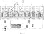
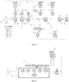
- the figure 30 discloses a processing system as previously described.
- the system further includes a cassette (601) for providing fluid dispensing functions.
- This cassette (601) is connected to reservoirs (603, 604) and cooperates with a device (602).
- the device (602) called a dialysis machine can be reusable while the cassette (601) can be disposable.
- the device (602) may include a processor (605), at least one sensor (606) adapted to cooperate with the cassette (601), at least one actuator (607) (for example pump or control means) adapted to cooperate with the cassette (601), a screen (608), at least one means acquisition and/or other such as a battery (609) and/or a memory (610).
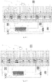
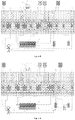
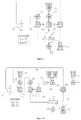
- the present document discloses a system (14) which makes it possible to carry out a treatment of the blood of a patient and which comprises a means for filtering the blood (3), at least one means for supplying liquid (F1), two patient pipes, an outlet pipe (5) taking the blood to be treated and an inlet pipe (6) reinjecting the treated blood into said patient, a filtrate recovery means (F4), at least three fluid pumps (P1, P2, P3), a cassette (2, 2') composed of channels and valves so as to direct the fluids.
- Said cassette (2, 2') comprises at least one distribution chamber (C1, C1.2, C7) comprising a single input channel and at least two output channels.
- Said treatment system (14) comprises a controller which controls the opening and closing of said valves according to the desired treatment.
- Said treatment system (14) further comprising a first fluidic path, connecting said blood filtration means (3) to the filtrate recovery means (F4), composed of a series of channels and a dedicated pump (P3 ); a second fluid path dedicated to blood circulation, comprising a series of channels, said blood filtration means (3), said patient hoses (5, 6) and a dedicated pump (P1); a third fluid path composed of a liquid supply means (F1), at least one dedicated pump (P2), a series of channels, a heating means (4) and at least a distribution chamber (C1, C1.2).
- Said cassette may further comprise at least one flow control means designed to control the amount of liquid from the third fluidic path which flows into at least one of said outlet channels of said distribution chamber (C1). Furthermore, said at least one flow regulation means is controlled by said controller which may include the processor (605).
- Said cassette (2') can also contain the pumps and/or other elements.
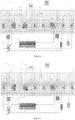
- the treatment system further comprises, in the third fluid path, a flow adjustment means (13, P2') located between said distribution chamber (C1) and said first connection chamber (C2).
- the third fluidic path comprises an additional pump (P2') in the third fluidic path, located between the distribution chamber (C1) and the said first connection chamber (C2).
- Said additional pump (P2') plays the total or partial role of flow adjustment means.
- the purpose of the flow adjustment means is to control the flow of fluid passing from the distribution chamber (C1) to the connection chamber (C2).
- the adjustment means thus makes it possible to distribute the quantity of fluid in the connection chamber (C2) and at least one other connection chamber or the blood filtration means (3).
- one or more flow adjustment means may be placed between any chamber or element (e.g. filter means blood (3)).
- a flow adjustment means (13) can be a pump, a proportional valve and/or a set of dedicated valve channels of different diameters, ...
- An additional safety valve can be added upstream or downstream of the means flow adjustment (13 - 520).
- a flow adjustment means allows a flow of 0% to 100% of the fluid at a given moment or during a given duration through said flow means. In other words, the flow of a fluid coming from at least one liquid supply means can be distributed in the different channels according to the needs of the treatment.
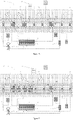
- the treatment system (14) comprises a second liquid supply means (F2 - 515) located on the patient outlet pipe (5) or in the cassette (2, 2' - 601).
- Said second supply means may contain an anticoagulant such as citrate, heparin, danaparoid sodium or the like.
- said system (14) comprises a third liquid supply means (F3 - 516) located on the patient's inlet pipe (6) or in the cassette (2, 2' - 601).
- Said liquid supply means may contain calcium or an anticoagulant inhibiting agent.
- the system comprises at least one safety element (7) making it possible to detect air bubbles in the second fluid path and/or stopping the circulation of blood and/or a means of capturing said air bubbles.
- the fluid delivery system may include a precision pump (702), a fluid supply means , a flexible bag (703) and an additional distribution pump (707).
- the system further comprises a main fluidic path (701) which is divided into at least two secondary and distinct fluidic paths (704, 704').
- the precision pump (702) and the flexible bag (703) are positioned in the main fluid path (701), the flexible bag being positioned downstream of said pump.
- the additional pump (707) is positioned in one of the secondary fluid paths (704).
- the other secondary fluid path (704') may include a valve (705).
- at least one fluid path includes a pressure sensor (706) positioned downstream of the precision pump (702). Said pressure sensor (706) can be positioned in the secondary fluid path (704) which includes the additional pump (707) and upstream of the additional pump.
- the flexible bag (703) can be a heating means.
- the heating means (4) can be located at different places of the third fluid path.
- the cassette has a heating means (4) inside the distribution chamber (C1) or upstream of the latter.
- the heating means (4) is a flexible pocket, located between the main pump (P2) of said third fluid path and said distribution chamber (C1) which makes it possible to create a constant positive pressure in said pocket (4).
- the heating pocket is continuously supplied by the pump (P2) which makes it possible, among other things, to guarantee good control of the heating of the liquid of the third fluid path.
- Said bag (4) is then directly connected to the inlet channel (V9) of the distribution chamber (C1).
- the cassette can comprise a connection chamber allowing the intersection of said two fluidic paths.
- the processing system may include peristaltic pumps. This type of pump may experience some inaccuracy.
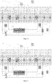
- the dispensing system comprises at least two volume sensors for measuring the volumes of the third and first fluid paths.
- the first sensor (15) is included in the third fluid path between the distribution chamber (C1) and the main pump (P2) and measures the injected volume coming from the first liquid supply means (F1, F1').
- the sensor (15) can be located after the heating means (4).
- the second sensor (17) is placed in the first fluid path downstream of the pump and before any other chamber. Said second sensor (17) measures the volume of filtrate withdrawn. To avoid any risk of contamination, the two sensors can be located in the cassette.
- said third sensor can be located in the cassette.
- the first and second sensors (15, 17) are adjusted to a common sensor called the reference sensor (16) for optimum relative precision. Said sensors, even inaccurate, are sufficiently effective since they are accurate in comparison (relative) with respect to the reference sensor (16).
- Said reference sensor (16) may be a scale, a volumetric pump, a mass flow sensor or any sensor making it possible to measure or deduce a volume.
- Said first and second sensors (15, 17) can continuously measure liquids passing through the third and first fluid paths respectively. Thanks to the continuous measurement of the volumes, the compensation of a possible drift is possible.
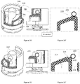
- the present document discloses a fluid distribution system (100) (for example a cassette as described previously) which makes it possible to withdraw and/or deliver a fluid FI1 from and/or to the patient and to measure the pressure of said fluid FI1 .
- the system comprises a rigid body (105) composed of at least one fluid path (103) through which said FI1 fluid flows and at least one channel (102). Said channel (102) is separate from the fluidic path (103) and makes it possible to connect said fluidic path to a measurement zone (101).
- the system further comprises at least one opening (106) covered by a flexible membrane (104) forming said measurement zone.
- the membrane is shaped to receive a pressure sensor (107).
- a fluid FI2 different from the fluid FI1 is contained in said measurement zone (101).
- the FI2 fluid extends at least partially into said channel (102).
- Said fluid FI2 makes it possible to transmit by contact the pressure of fluid FI1 to said membrane (104).
- Said channel (102) is a flow restrictor shaped so that said FI1 fluid cannot come into contact with said membrane.
- the length and/or the shape of said pressure transmission channel (102) depends on the expansion capacity of said fluid FI2 and/or on the pressure range to be measured.
- the channel (102) may comprise at least one section narrow enough to retain the FI1 fluid so that said fluid does not enter said measurement zone (101).
- the channel (102) includes a hydrophobic filter (108) or membrane.
- a membrane (104) / fluid (FI3) / sensor cell (107) interface is created so as not to have friction of the membrane (104) on said cell which could create disturbances on the measurement.
- a liquid (FI1)/fluid (FI2)/membrane (104) interface is created to prevent the membrane (104) from being wetted by the liquid (FI1).
- the transmission of the pressures of FI1 is ensured by the fluids FI2 and FI3, arranged on each side of the membrane (104).
- FI2 and FI3 can be the same physical properties.
- FI2 and FI3 can be air.
- Said membrane (104) can deform with equivalent stresses on each side of these faces and this to compensate for the variations in volume of air, trapped between the membrane (104) and the sensor (107), due to the temperature.
- the fluid FI1 is of aqueous nature whereas FI2 is of lipidic nature, FI3 being able to be of lipidic or aqueous nature.
- the picture 13' discloses a fluid delivery system (100) which allows the flow of an FI1 fluid and to measure the pressure of said FI1 fluid.
- the system comprises a rigid body (105) composed of at least one fluid path (103) through which said FI1 fluid flows and at least one channel (102).
- the channel (102) is separate from the fluid path (103) but communicates so that FI1 fluid can flow through the channel (102).
- the channel (102) makes it possible to connect said fluidic path to a measurement zone (101).
- the system further comprises at least one opening (106) covered by a flexible membrane (104) forming said measurement zone. Said opening (106) can be of equal or different size from the size of the channel (102). Further, the membrane is shaped to receive a pressure sensor (107).
- a fluid FI2 different from the fluid FI1 is contained in said measurement zone (101).
- the fluid FI2 is contained at least in part in the measurement zone and/or in the channel (102).
- the quantity and/or the volume of the fluid FI2 is constant or can decrease over time so that the fluid FI1 progresses more or less rapidly in the channel (102) and/or the measurement zone (101).
- the measurement zone (101) and/or the channel (102) contain at least partially the fluid FI2 and the fluid FI1.
- the FI1 fluid may partially wet or be in contact with the membrane (104).
- the length and/or the shape of said pressure transmission channel (102) depends on the expansion capacity of said fluid FI2 and/or on the pressure range to be measured.
- the channel (102) can be shaped so as to limit and/or slow down the progression of the FI1 fluid, for example during the use of said system.
- the fluid distribution system (100) can be adapted to ensure that the membrane (104) and/or the measurement zone (101) are not fully wetted by or in contact with the FI1 fluid during the use of this system.
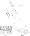
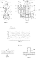
- a linear actuator (200) using a motor (for example a direct current motor (also called DC motor) or another type of motor known to those skilled in the art) (201) coupled to interposed means making it possible to transform the rotation of the motor axis into a linear movement.
- the motor may also include a torque reducer.
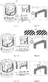
- Said ramp (214) comprises at least one threshold, one threshold (215) of which is located at the top of said ramp (214).
- the threshold is shaped so as to cooperate with the bearing means.
- the threshold can be perfectly flat, horizontal with respect to the vertical movement of the piston.
- the threshold can also have a specific shape to ensure good support of the support means in order to guarantee the maintenance of the position, for example, the right embodiment of the picture 18' .
- the threshold (215) located at the top of said ramp (214) is followed by a passage (219) allowing the piston (207) to free itself from the stresses exerted by said support means (209).
- the piston may include one or more ramps and/or one or more passages. At least one ramp can have an inclination between 0 and 90°. In one embodiment, said inclination may be between 0 and 45°, between 10 and 30°.
- the ramp is followed by at least one passage, for example after a threshold.
- said actuator further comprises at least one compression means (205) which exerts a force against the piston (207).
- the support means and the ramp cooperate in order to move the piston along the same axis as the force exerted by the compression means but in the opposite direction.
- said compression means tends to push the piston (relative to the actuator) (that is to say in the direction (220) of the distal end of the piston (217)) while the support means and the ramp force the piston to move closer to the actuator.
- said compression means tends to bring the piston closer of the actuator while the support means and the ramp force the piston to move away from the actuator. In this case, A ⁇ B.
- the purpose of the actuator is to drive an element of a device as described in this document. It may for example be a valve of the cassette. The remainder of the description describes this embodiment.
- the piston has a third position, where the pin (211) of the piston (207) is decoupled from the valve (212).
- a compression means (205 exerts a force against the piston, moving said piston to a third position farther from the engine than the first and second position. It can be the same compression means described above or a compression means
- d2 is equal to C.
- the interest of this third position is to guarantee sufficient occlusion pressure when the piston is coupled to the valve in the first position. otherwise, when the piston is coupled to the valve, the piston exerts a force against the valve to cause the valve to close when the piston is in the first position.
- the actuator comprises an element for fixing to its support comprising a compression means exerting a force in the direction of the distal end of the piston and having the same function described above.
- Said compression means (205) can be a spring, an elastic blade, a rubber band or a shape memory material. Said compression means (205) can exert a force of 0 to 6N, for example between 5 and 6N.
- the actuator (200) is designed with the aim of not consuming energy when maintaining a stationary position.
- the bearing means (209) is adapted to slide or roll on the ramp to reach a position.
- said threshold is shaped so that the assembly is in equilibrium.
- the threshold (215) at the top of the ramp (214) is directly followed by a passage (219) allowing the piston to pass quickly from a second position to a first position while consuming a minimum of energy.
- Said passage makes it possible to pass from one position to the other with a small amount of energy. In other words, the energy consumed by the actuator to pass from the first position to the second position is greater than the energy consumed by the actuator to pass from the second position to the first position.
- the passage (219) can be a ramp having a high slope and/or in the opposite direction to the slope of the ramp. Thus, the support means travels a shorter distance to pass from the second position to the first than vice versa.
- the piston (207) comprises several thresholds in order to have intermediate rest positions.
- the motor comprises a torque reducer between the motor and the rotor of the interposed means.
- Said torque reducer can be designed so that the motor can rotate the rotor but the rotor cannot rotate the motor.
- the torque reducer can, thanks to its design, prevent or limit or slow down any movement of the rotor which would not be caused by the motor.
- the torque reducer can be designed so that the actuator can maintain any position when the motor is stationary (powered or not).
- the actuator can comprise a limited number of thresholds as described previously but an unlimited number of positions which can be maintained thanks to the torque reducer without the actuator being supplied with current.
- Such an actuator can be adapted to cooperate with a proportional valve of a fluid distribution cassette.
- the actuator can allow the flow of a fluid in proportion to the need for the treatment.
- the piston (207) may not include a threshold but only maintainable positions thanks to the torque reducer as described above.
- This piston thus comprises at least one ramp and optionally one passage.
- the torque reducer allows the actuator to maintain a given position allowing the opening from 0% to 100% of a valve (for example a proportional valve).
- the piston includes at least one lower ramp and one upper ramp. Said ramps being adapted so that at least one support means (209) can move between said ramps. Said ramps can at least partly be parallel to each other.
- At least one actuator is included in an actuation system that includes a controller and at least one power supply means.
- Said system is designed to move at least one piston from a second position to a first position and vice versa while consuming a small amount of energy.
- Said energy supply means can be an external power supply and/or an energy storage means. Said energy storage means can be used by the system when said external power supply is no longer operational or insufficient.
- said energy storage means which may be a supercapacitor or a battery.
- the piston (207) and the rigid casing (202) comprise guide means (203, 216) in order to prevent the piston from rotating with the rotor (208) of the motor.
- a control system (800) comprises a linear actuator comprising a movable part (801) and a fixed part (804) as well as control and command elements (802, 803, 805).
- the control and command elements are suitable for knowing the position of the mobile part (801) relative to the fixed part (804) and for controlling the linear actuator.
- the figure 32 exposes the actuator in a position A and the picture 32' exposes the actuator in a position B.
- the control element (805) controls the actuator, the fixed part (804) of which may comprise the drive means (for example a motor).
- the mobile part (801) can be adapted to cooperate with, for example, a valve of a fluid distribution system.
- position A could correspond to the closed position of the valve to be controlled and position B could correspond to the open position of said valve,
- the elements 1 (802) and 2 (803) of the sensor are designed to cooperate and determine at least one position. It can be a capacitive or inductive displacement sensor (LVDT, etc.), an electromagnetic sensor (hall effect sensor), ultrasonic, infrared, optical, laser, mechanical or microwave sensor (non-exhaustive list ).
- LVDT capacitive or inductive displacement sensor
- element 1 (802) is a permanent magnet (in this case, it is not connected to the processor) (805)
- element 2 (803) is a hall effect sensor connected to the processor.
- the permanent magnet creates an electromagnetic field whose intensity the sensor (803) measures.
- the sensor (803) makes it possible to detect the variation of the magnetic field induced by the permanent magnet (802) when it moves.
- the permanent magnet (802) can be rigidly fixed permanently to the movable part (801) of the actuator and the sensor (803) is rigidly fixed permanently to the fixed part (8004) of the actuator (or Conversely).
- the permanent magnet (802) approaches or moves away from the sensor (803) which thus measures a variation in the intensity of the magnetic field of the permanent magnet (802).
- the magnet and the sensor are aligned.
- the measurement data from the sensor (802) is transmitted to the processor to process the signal.
- all control systems must be qualified in order to determine in advance the intensity corresponding to each position.
- the sensor detects predetermined value thresholds corresponding to respective positions determined in advance.
- this qualification work for example calibration which must be performed at all actuators
- this document discloses the use of a processor which performs signal processing to determine at least one position of the actuator. Thus, this makes it possible, for example, not to carry out a calibration.
- the upper graph of the figure 33 makes it possible to highlight that the absolute value (the intensity of the electromagnetic field of the magnet measured by the sensor) can be very different from one actuator to another. Indeed, the sensors of actuators 1 and 2 do not detect the same intensity (in absolute value) although their position is identical. Thus, it would be difficult and unreliable or even impossible to determine the position of these actuators according to a single threshold value.
- the control system (800) includes a processor (805) that uses a mathematical model taking into account the derivative of the absolute value.
- the absolute value is the value measured by the sensor (803), it corresponds to the intensity of the magnetic field.
- the absolute value curve is represented by the upper graph of the figure 33 .
- the derivative of the absolute value is the leading coefficient of the curve drawn by the absolute value.
- the derivative makes it possible to know the slope of the variation of the magnetic field when the magnet moves relative to the sensor.
- This derivative is represented by the curve of the graph in the middle of the figure 33 .
- this derivative makes it possible to know the direction of the displacement of the movable part (801) of the actuator with respect to its fixed part (804).
- the control system thus comprises a processor using a mathematical model which takes account of the derivative of the signal. Thanks to this mathematical model, it is possible to know when the actuator has reached a position or a threshold as described in the chapter disclosing the linear actuator. Indeed, when the actuator moves its mobile part (801) the first derivative is greater or less than 0 but when the actuator does not move its mobile part (801), its first derivative is substantially equal to 0. In our example , when the magnet (802) moves away from the sensor (803) the first derivative is negative and conversely when the magnet approaches, the first derivative is positive.
- the system may further include a mathematical model to determine when the moving part moves and when it remains stationary.
- This second mathematical model takes into account the second derivative of the absolute value. Thanks to this second model mathematical, the system knows when the mobile part changes its behavior (mobile or stationary).
- control system includes an actuator comprising at least one ramp and at least one threshold (eg, a linear actuator as described herein), a processor adapted to control the actuator and to process the signal according to at least one mathematical model.
- actuator comprising at least one ramp and at least one threshold (eg, a linear actuator as described herein)
- processor adapted to control the actuator and to process the signal according to at least one mathematical model.
- a first mathematical model takes into account the first derivative of the absolute value measured by the sensor (803).
- the processor can use this first mathematical model in order to know in which direction the mobile part (801) moves.
- the control system knows that the actuator has reached a threshold.
- a second mathematical model takes into account the second derivative of the absolute value measured by the sensor (803).
- the processor can use the second mathematical model in order to know when a threshold is reached and/or when the moving part is stationary or moving.
- the lower graph of the figure 33 represents the signal resulting from the second mathematical model.
- the signal is equal to the value f, this means that the actuator maintains a position or is on a threshold.
- the signal is equal to the value d, means that the mobile part (801) moves.
- the system does not need the absolute value.
- the control system supplies the actuator to move its mobile part (801)
- the second mathematical model makes it possible to know when the actuator has reached a position.
- the processor when the actuator continues its actuation (for example, it rotates the support means (209)) but the moving part no longer moves, thanks to the first and/or second derivative, the processor is capable of know that the means of support has reached a threshold.
- the processor orders the actuator to change position, a mathematical model allows the processor to know when the threshold has been reached and thus orders the actuator to stop.
- said control system is suitable for determining at least one position reached by the moving part (801) of the actuator independently of the characteristics of the sensor used.
- Said control system is suitable for controlling the stoppage of the actuator at at least one position reached by the moving part (801) of the actuator independently of the characteristics of the sensor used.
- the control system comprises an actuator comprising at least two distinct positions.
- the actuator comprises at least one threshold defining a position and at least one ramp making it possible to change position.
- the actuator is driven by a motor designed to rotate for example in one direction only so that it moves from one position to another sequentially and in a pre-established order.
- the actuator can be adapted to return to its starting position by carrying out at least a partial revolution.
- the processor includes a mathematical model which takes account of the second derivative of the absolute value measured by said sensor.
- Said processor comprises a memory which contains the sequence of positions so that said system does not need to know the first derivative of the absolute value to know the position of the actuator. It suffices for the actuator to perform one revolution to know its position precisely, for example, when starting up the system.
- the treatment system may include a drive device used for peristaltic pumps.
- Said driving device disclosed herein can also be used by various peristaltic pumps and/or fluid delivery systems comprising a peristaltic pump.
- a drive device which comprises a floating shaft (301) driven by a drive means (303) fixed to a rotor (310) of an electric motor (not shown).
- Said floating shaft (301) comprises an integral base (311)/cover (302) assembly containing a cavity inside which said drive means (303) is at least partially circumscribed.
- Said driving means (303) comprises a rigid body shaped so as to cooperate with the walls (309, 309') of said cavity (313) in order to allow a restricted freedom of the floating axis (301) with respect to the axis of said rotor (310).
- a screw (307) can make it possible to fix the drive means (303) to said rotor (310).
- the cavity comprises at least one cooperation element (312) which allows said drive means (303) to transmit a rotational movement to said floating axis.
- Said cooperating element (312) may be an opening bounded by two hard elements (308) and through which an axis (306) is housed perpendicularly. The space between the two hard elements (308) is reasonably greater than the diameter of the axis (306).
- the hard elements (308) and/or the axis (306) can be made from hard metals such as cobalt, tungsten, vanadium, chromium, manganese, nickel, titanium, germanium, gallium, bismuth, iridium, lithium, magnesium , molybdenum, strontium, rubidium or palladium.
- the hard elements (308) have a greater hardness than the shaft (306).
- the hard elements (308) and/or the pin (306) can receive a treatment to increase their hardness, for example zirconium oxide or one of its alloys.
- the body (304) of said drive means (303) may be perfectly round or partially flattened spherical in shape.
- said body (304) forms a roller comprising three faces. Two of the three faces oppose each other and are interconnected via the third face which is curved. According to the X-Z plane, said roller forms a circle formed by said curved face. The connection between at least one of the two faces which oppose the curved face can be rounded along the X-Y plane.
- the opposing faces can be substantially planar and/or substantially parallel to each other.
- the cavity (313) includes smooth walls (309, 309').
- the upper wall (309) and/or the lower wall (309') of said cavity (313) may be of at least partially conical shape.
- the surfaces of the top (309) and bottom (309') walls can be flat or curved.
- the cone of the smooth wall (309) is defined according to an angle comprised between 0 and 90°, for example between 5 and 30°.
- the cone of the opposite smooth wall (309') is defined according to an angle between -0 and -90°, for example between -5 and -30°.
- the angles of the two partial cones can be equal or different.
- the smooth walls (309, 309') are adapted to cooperate with the ends of the body (304) so that the floating axis (301) can move along at least the three axes X, Y or Z and/or undergo pitching movements. For example, along the Y axis, the floating axis (301) can undergo a pitch movement of +/- 10°, for example less than +/- 5°.
- the drive means (303) comprises a longitudinal axis (305) and the floating axis (301) comprises a second cavity (313') which is extends along the floating axis.
- the longitudinal axis (305) is inserted inside the second cavity (313') in order to restrict the pitching movements of the floating axis (301).
- the dimensions of the elements forming the drive means (303, 306, 305) are reasonably smaller than the elements forming the inside of the floating shaft (301, 302, 313, 312).
- the drive system (300) includes a one piece drive shaft which extends along the Y axis and which is adapted to drive at least one roller (320) of a peristaltic pump system. Said roller is suitable for crushing a flexible tube (not shown) against a wall (not shown).
- the drive axis is represented by the floating axis (301).
- the drive shaft can be the floating shaft and/or merged with part of the drive system.
- the drive shaft can be cylindrical in shape and include a bevelled free end (here the term free end is opposed to the opposite end which is linked directly or indirectly to the motor).
- the drive shaft cylinder forms a circle along an XZ plane.
- said drive shaft is formed from a single piece composed of at least two different cylinders defined by the same axis (in other words the center of the cylinder) but having different diameters.
- the drive axis can form at least two parallel circles but of different sizes.
- the drive shaft may comprise three cylinders of which only one is of different diameter.
- the cylinder defined by the smaller diameter can be arranged between the two cylinders of equal diameter.
- Said larger diameter cylinders may have surfaces treated so as to improve cooperation with the rollers of the peristaltic pump.
- This construction of the three-cylinder drive shaft is particularly suitable and advantageous for the use of an H-shaped roller, such as the roller (320) of the figure 23 .
- the roller is included in a peristaltic pump system and crushes a flexible pipe.
- the crushing function can be performed by a rigid part (322) of the roller (320).
- Said roller (320) is a cylinder forming a circle on the XZ plane and comprises an axis (321) at the center of this cylinder which extends along the Y axis, a rigid part (322) and at least one flexible part (323) which is deformable.
- the flexible part is adapted to cooperate with the drive shaft.
- the larger diameter cylinders can come into contact with the flexible parts (323) of the roller (320) and cause the roller (320).
- said flexible part (323) can deform in order to improve the cooperation between these two elements and/or to adjust the tolerance errors of each of the elements.
- the roller can comprise a rigid part (322) in its center and two flexible parts (323) at the ends along the Y axis.
- a fluid distribution system comprising a floating shaft (301), a three-cylinder drive shaft and/or a roller with rigid and flexible parts makes it possible to substantially improve the roller / drive shaft cooperation and to correct errors tolerance of the various elements of the system.
- the treatment system comprises at least one means for damping the pressure peaks.
- the figure 24 shows the pressure signal measured near the inlet of a peristaltic pump.
- the first curve (401) it is possible to observe the oscillation of the pressure while the second curve (402) represents the mean value of this pressure.
- the purpose of the damper is to reduce the amplitude of the oscillations of the first curve (401).
- damping means can be installed in one or more fluid paths of a distribution system as described above. This damping means can be integrated into a cassette.
- each treatment has one or more possible configurations.
- the phenomenon of pressure peaks can be amplified or attenuated by various elements which vary according to said configurations. Reproducibility is thus an important element because the operator (generally the nurse) must be able to ensure the correct operation of the system without being obliged to take into account the characteristics of the various elements.
- the delivery system as disclosed herein may be a cassette through which fluids flow in three fluid paths. These fluids can be propelled by peristaltic pumps. Reproducibility, accuracy and patient comfort are important.
- at least one damping means can be integrated into said cassette. To be as effective as possible, said damping means must be placed as close as possible to the pumping system.
- the fluidic path comprises walls (404) delimiting said path. These walls can be the rigid walls of the cassette.
- a section of the fluid path is covered with a flexible membrane (403) which then replaces said wall (404). Thanks to the elasticity of said flexible membrane (403), the pressure peaks are substantially attenuated, absorbed by the deformation of the membrane (403). The absorption of these peaks is a function of the size and the elastic characteristics of the membrane.
- the fluidic path also comprises walls delimiting said path but one section is replaced by a cavity filled with a compressible fluid such as air.
- a compressible fluid such as air.
- This air may have been trapped (about 1mL) when priming the system.
- the air volume is more or less compressed during the pumping, absorbing the energy of the pressure peaks.
- This embodiment is particularly effective because it requires little energy for its operation and said fluid absorbs pressure peaks very quickly.
- the cavity or the entrance to the cavity can be designed to prevent the compressible fluid from completely escaping. In other words, the cavity can be designed to prevent the flowing fluid from replacing the compressible fluid.
- Said damping means can be placed upstream of the pumping mechanism.
Landscapes
- Health & Medical Sciences (AREA)
- Heart & Thoracic Surgery (AREA)
- Engineering & Computer Science (AREA)
- Vascular Medicine (AREA)
- Public Health (AREA)
- Hematology (AREA)
- Life Sciences & Earth Sciences (AREA)
- Animal Behavior & Ethology (AREA)
- General Health & Medical Sciences (AREA)
- Anesthesiology (AREA)
- Veterinary Medicine (AREA)
- Biomedical Technology (AREA)
- Urology & Nephrology (AREA)
- Cardiology (AREA)
- Emergency Medicine (AREA)
- Mechanical Engineering (AREA)
- General Engineering & Computer Science (AREA)
- External Artificial Organs (AREA)
- Physics & Mathematics (AREA)
- Fluid Mechanics (AREA)
- Connection Of Motors, Electrical Generators, Mechanical Devices, And The Like (AREA)
- Medicines Containing Material From Animals Or Micro-Organisms (AREA)
Description
L'invention concerne un actionneur linéaire configuré pour ouvrir ou fermer une valve d'un dispositif médical tel qu'un système de distribution de fluide.A linear actuator configured to open or close a valve of a medical device such as a fluid delivery system.
Il existe plusieurs causes possibles pour qu'une personne soit atteinte d'une insuffisance rénale où l'arrêt temporaire/définitif et partiel/total contraint cette personne à utiliser des dispositifs extra corporel qui se substitue totalement ou partiellement à ses propres reins. La dialyse est une technique de purification du sang. Elle permet, à un patient souffrant d'une telle maladie, d'éliminer les impuretés telles que l'urée et l'excès d'eau de l'organisme qui auraient été habituellement éliminé par des reins fonctionnants normalement.There are several possible causes for a person to suffer from kidney failure where temporary/permanent and partial/total arrest forces this person to use extra-corporeal devices which totally or partially replace their own kidneys. Dialysis is a blood purification technique. It allows a patient suffering from such a disease to eliminate impurities such as urea and excess water from the body which would normally have been eliminated by normally functioning kidneys.
Il est possible de distinguer deux types d'insuffisance rénal liés à la durée de la maladie et nécessitant des soins pouvant être sensiblement différents : l'insuffisance rénale chronique et l'insuffisance rénale aigüe. Une insuffisance rénale chronique contraint le patient à suivre un traitement à vie et à une certaine fréquence. Pour cela, le patient peut effectuer ce traitement dans un centre médical ou à domicile à l'aide d'un appareil à dialyse péritonéale ou à hémodialyse. Une insuffisance rénale aigüe est une maladie temporaire où le patient a besoin d'un appareil pour remplacer temporairement les fonctions de ses reins. Dans ce cas, le patient suit une thérapie d'épuration extra-rénale continue. La dialyse péritonéale et la thérapie d'épuration extra-rénale continue sont très différentes ainsi que les techniques et/ou dispositifs utilisés :
- La dialyse péritonéale utilise le péritoine du patient qui est la membrane naturelle qui enveloppe les parois du ventre et les organes situés dans le ventre (foie, intestins, etc..). La membrane péritonéale dispose d'une très grande surface et elle comporte de très nombreux vaisseaux sanguins. Elle joue ainsi le rôle de filtre naturel. De nombreux brevets divulguent des systèmes permettant d'effectuer des dialyses péritonéales dont certains utilisant des cassettes (
EP 1 648 536 A2EP 0 471 000 B1 EP 1 195 171 B1EP 1 648 536 B1 - La thérapie d'épuration extra-rénale continue (appelé CRRT en anglais : Continuous Renal Replacement Therapy) est un procédé nécessitant d'extraire en continue le sang du patient, de le traiter grâce à un filtre, généralement un dialyseur puis de réinjecter le sang traité au patient. Deux grands principes sont utilisés grâce au filtre :
- o La diffusion permet le passage de molécules de soluté à travers une membrane semi-perméable selon un gradient de concentration. Les solutés vont du milieu le plus concentré (le sang) vers le milieu le moins concentré (le dialysat) pour se répartir de façon uniforme de part et d'autre de la membrane du filtre.
- ∘ La convection permet le transfert simultané de l'eau et de son contenu en solutés au travers de la membrane semi perméable, grâce au gradient de pression hydrostatique transmembranaire. Ainsi, les solutés vont du milieu où la pression est la plus forte (compartiment du sang) vers le milieu où la pression est la plus faible (compartiment du dialysat).
- Peritoneal dialysis uses the patient's peritoneum, which is the natural membrane that envelops the walls of the stomach and the organs located in the stomach (liver, intestines, etc.). The peritoneal membrane has a very large surface area and contains many blood vessels. It thus acts as a natural filter. Many patents disclose systems for performing peritoneal dialysis, some of which use cassettes (
EP 1 648 536 A2EP 0 471 000 B1 EP 1 195 171 B1EP 1 648 536 B1 - Continuous renal replacement therapy (CRRT) is a process that involves continuously extracting the patient's blood, treating it through a filter, usually a dialyzer, and then reinjecting the blood. treated to the patient. Two main principles are used thanks to the filter:
- o Diffusion allows the passage of solute molecules through a semi-permeable membrane according to a concentration gradient. The solutes go from the most concentrated medium (the blood) to the least concentrated medium (the dialysate) to distribute themselves uniformly on either side of the filter membrane.
- ∘ Convection allows the simultaneous transfer of water and its solute content through the semi-permeable membrane, thanks to the transmembrane hydrostatic pressure gradient. Thus, the solutes go from the medium where the pressure is the strongest (blood compartment) to the medium where the pressure is the weakest (dialysate compartment).
Il existe différentes techniques d'épuration extra rénale continue utilisant un seul ou les deux principes : l'ultrafiltration continue lente (SCUF : Slow Continuous Ultra-Filtration), l'hémofiltration veino-veineuse continue (CWH : Continuous Ceno-Venous Hemofiltration), l'hémodialyse veino-veineuse continue (CWHD : Continuous Veno-Venous Hemodialyse), l'hémodiafiltration veino-veineuse continue (CWHDF : Continuous Veno-Venous Hemofiltration), l'échanges plasmatiques (TPE : Therapeutic Plasma Exchange) et l'hémoperfusion (appelé également Blood Detoxification). A ce jour, aucun dispositif n'est capable de proposer l'ensemble de ces traitements sans une intervention de personnels soignants expérimentés. En outre, ces techniques sont principalement utilisées en milieu de soins intensifs. Malheureusement, ces techniques utilisent des appareils volumineux qui peuvent gêner le bon fonctionnement des autres soins effectués sur le patient. De plus, ces appareils sont complexes, disposent de nombreux consommables et nécessite des changements importants pour effectuer les différentes techniques citées ci-dessus. Cela implique que le personnel reçoive une formation spécialisée.There are different continuous extra renal purification techniques using one or both principles: slow continuous ultrafiltration (SCUF: Slow Continuous Ultra-Filtration), continuous venovenous hemofiltration (CWH: Continuous Ceno-Venous Hemofiltration), continuous venovenous hemodialysis (CWHD: Continuous Veno-Venous Hemodialyse), continuous venovenous hemodiafiltration (CWHDF: Continuous Veno-Venous Hemofiltration), plasma exchange (TPE: Therapeutic Plasma Exchange) and hemoperfusion ( also called Blood Detoxification). To date, no device is capable of offering all of these treatments without the intervention of experienced caregivers. In addition, these techniques are mainly used in intensive care settings. Unfortunately, these techniques use bulky devices that can interfere with the proper functioning of other treatments performed on the patient. In addition, these devices are complex, have many consumables and require significant changes to perform the various techniques mentioned above. This implies that staff receive specialized training.
Le document portant le numéro de publication suivant
L'invention concerne un actionneur linéaire configuré pour ouvrir ou fermer une valve d'un dispositif médical comprenant un moteur électrique rotatif ayant un rotor définissant un axe, un piston et des moyens interposés entre le moteur électrique et le piston transformant un mouvement de rotation du moteur en un déplacement linéaire du piston ; lesdits moyens interposés comprenant :
- Une rampe périphérique disposée à l'intérieur dudit piston,
- Un moyen d'appui fixé au rotor dudit moteur électrique, ledit moyen d'appui étant façonné de manière à coopérer avec ladite rampe périphérique,
- Un moyen de guidage permettant au piston de guider le mouvement de translation,
- A peripheral ramp arranged inside said piston,
- A support means fixed to the rotor of said electric motor, said support means being shaped so as to cooperate with said peripheral ramp,
- A guide means allowing the piston to guide the translational movement,
Dans lequel la rampe est façonnée de manière à permettre audit piston d'être maintenu dans une première position stationnaire et une seconde position stationnaire et comprend :
- Un seuil localisé au sommet de ladite rampe qui en coopération avec le moyen d'appui permet au piston d'être maintenu dans la seconde position stationnaire et
- Un passage permettant au piston de se libérer des contraintes exercées par ledit moyen d'appui.
- A threshold located at the top of said ramp which, in cooperation with the support means, allows the piston to be maintained in the second stationary position and
- A passage allowing the piston to free itself from the stresses exerted by said bearing means.
L'invention concerne également un système de distribution de fluide d'un dispositif médical comprenant un chemin fluidique et un actionneur configuré pour ouvrir et fermer le chemin fluidique, dans lequel l'actionneur comprend :
- • Un moteur électrique rotatif ayant un rotor et un moyen d'appui fixé au rotor et
- • Un piston comprenant une rampe périphérique, agencée de manière à coopérer mécaniquement avec le moyen d'appui du rotor, un seuil et un passage ;
- • A rotary electric motor having a rotor and a support means fixed to the rotor and
- • A piston comprising a peripheral ramp, arranged so as to cooperate mechanically with the bearing means of the rotor, a threshold and a passage;
Dans lequel le piston et le moyen d'appui sont configurés pour transformer un mouvement de rotation du moteur électrique en un déplacement linéaire du piston guidé par un moyen de guidage et de permettre au piston d'atteindre :
- Une première position stationnaire, où le moyen d'appui se trouve dans le passage libérant le piston des contraintes exécrées le moyen d'appui et
- Une seconde position stationnaire où le moyen d'appui se trouve sur le seuil.
- A first stationary position, where the support means is in the passage releasing the piston from the constraints execrated the support means and
- A second stationary position where the support means is on the threshold.
Le présent document divulgue également de multiples améliorations pour dispositifs médicaux, moyens et/ou méthode utilisé pour des dispositifs médicaux.This document also discloses multiple improvements for medical devices, means and/or methods used for medical devices.
La présente demande revendique la priorité de la demande portant le numéro PCT/IB2012/055972, déposée le 29 octobre 2012 au nom de Debiotech.This application claims the priority of the application bearing the number PCT/IB2012/055972, filed on October 29, 2012 in the name of Debiotech.
Un premier aspect de la divulgation non compris dans l'invention revendiquée dans ce présent document est relatif à une unique cassette permettant d'effectuer une ou l'ensemble des différentes techniques d'épuration extra rénale continue : l'ultrafiltration continue lente (SCUF), l'hémofiltration veino-veineuse continue (CWH), l'hémodialyse veino-veineuse continue (CWHD), l'hémodiafiltration veino-veineuse continue (CWHDF), l'échanges plasmatiques (TPE) et l'hémoperfusion. Dans un mode de réalisation non compris dans l'invention revendiquée dans ce présent document, le dispositif peut également être utilisé dans le cadre d'une dialyse péritonéale où certains éléments et/ou caractéristiques pourraient ne pas être utilisés ou être utilisés pour d'autres fonctionnalités tel que l'échantillonnage ou autres. Dans mode de réalisation, la cassette est partiellement ou entièrement intégré dans l'appareil de dialyse ou certain de ces éléments font partie dudit appareil (par exemple le système de pompage, les capteurs, le filtre, ...) ou sont séparés physiquement de la cassette (par exemple le filtre, moyens d'alimentations, les réservoirs, les capteurs, le moyen de chauffage...) ou sont optionnels. Ladite cassette et l'appareil de dialyse peuvent être tous deux distincts. La casette est jetable alors que l'appareil est réutilisable. Cela signifie, que la cassette peut être remplacée à chaque traitement (utilisation unique, remplacement de la cassette après chaque utilisation) et que l'appareil peut être utilisé à plusieurs reprises avec différentes casettes. Lesdites cassettes sont conçues pour coopérer physiquement et/ou mécaniquement avec l'appareil et/ou vice-versa. En outre, l'utilisation d'une seule cassette permet de simplifier l'utilisation dudit dispositif, réduire les erreurs des opérateurs grâce à cette simplification, automatiser le traitement sans intervention de personnel soignant, limiter le nombre de type de cassette, simplifier la programmation, permettre l'utilisation du dispositif chez le patient et/ou limiter la place occupée par le dispositif.A first aspect of the disclosure not included in the invention claimed in this document relates to a single cassette making it possible to carry out one or all of the different techniques of continuous extra renal purification: slow continuous ultrafiltration (SCUF), continuous venovenous hemofiltration (CWH), continuous venovenous hemodialysis (CWHD), continuous venovenous hemodiafiltration (CWHDF) , plasma exchange (TPE) and hemoperfusion. In an embodiment not included in the invention claimed herein, the device can also be used in the context of peritoneal dialysis where certain elements and/or characteristics may not be used or may be used for other functionalities such as sampling or others. In one embodiment, the cassette is partially or entirely integrated into the dialysis device or some of these elements are part of said device (for example the pumping system, the sensors, the filter, etc.) or are physically separated from the cassette (for example the filter, supply means, tanks, sensors, heating means, etc.) or are optional. Said cassette and the dialysis machine can both be separate. The cassette is disposable while the device is reusable. This means that the cassette can be replaced with each treatment (single use, replacement of the cassette after each use) and that the device can be used several times with different cassettes. Said cassettes are designed to cooperate physically and/or mechanically with the device and/or vice versa. In addition, the use of a single cassette makes it possible to simplify the use of said device, reduce operator errors thanks to this simplification, automate the treatment without the intervention of nursing staff, limit the number of cassette types, simplify programming , allow the use of the device in the patient and/or limit the space occupied by the device.
Selon un deuxième aspect de la divulgation non compris dans l'invention revendiquée dans ce présent document, le dispositif peut comprendre seulement 3 pompes principales pour effectuer au moins une ou l'ensemble des techniques citées dans l'état de l'art (SCUF, CW, CWH, CVVHDF, TPE et l'hémoperfusion).According to a second aspect of the disclosure not included in the invention claimed in this document, the device can comprise only 3 main pumps to perform at least one or all of the techniques cited in the state of the art (SCUF, CW, CWH, CVVHDF, TPE and hemoperfusion).
Selon un mode de réalisation non compris dans l'invention revendiquée dans ce présent document, le dispositif comprend un moyen de filtration du sang, au moins un moyen d'alimentation en liquide, deux tuyaux patient - un tuyau de sortie prélevant le sang à traiter et un tuyau d'entré réinjectant le sang traité audit patient - (ou un seul tuyau en cas de dialyse péritonéale ou un tuyau avec deux lumières distincts), un moyen de récupération du filtrat, trois pompes à fluide, une cassette composée de canaux et de valves de manière à diriger les fluides, et un contrôleur qui commande les pompes, l'ouverture et la fermeture desdites valves en fonction du traitement souhaité.According to an embodiment not included in the invention claimed in this document, the device comprises a blood filtration means, at least one liquid supply means, two patient pipes - an outlet pipe taking the blood to be treated and an inlet pipe reinjecting the treated blood into said patient - (or a single pipe in the case of peritoneal dialysis or a pipe with two separate lumens), a filtrate recovery means, three fluid pumps, a cassette made up of channels and valves so as to direct the fluids, and a controller which controls the pumps, the opening and the closing of said valves according to the desired treatment.
Ladite casette comprend aux moins une chambre de distribution comprenant un seul canal d'entrée, au moins deux canaux de sortie et aux moins deux chambres de raccordement comprenant au moins deux canaux d'entrée et un canal de sortie. Ladite chambre de distribution peut comprendre un canal d'entré et trois canaux de sortie commandés par le contrôleur (de façon automatique, programmé et/ou commandé) afin de permettre à un fluide d'être injecté dans le moyen de filtration du sang, dans le sang avant le moyen de filtration du sang (pré dilution) et/ou après le moyen de filtration du sang (post dilution). Grâce à cette chambre de distribution, le dispositif peut effectuer n'importe quel traitement par dialyse sans que le personnel soignant (ou autre spécialiste) ne soit présent pour configurer les branchements spécifiques de chaque traitement.Said cassette comprises at least one distribution chamber comprising a single input channel, at least two output channels and at least two connection chambers comprising at least two input channels and one output channel. Said distribution chamber may comprise an input channel and three output channels controlled by the controller (automatically, programmed and/or controlled) in order to allow a fluid to be injected into the blood filtration means, in the blood before the blood filtration means (pre dilution) and/or after the blood filtration means (post dilution). Thanks to this distribution chamber, the device can carry out any dialysis treatment without the nursing staff (or other specialist) being present to configure the specific connections for each treatment.
Ledit système de traitement comprend en outre au moins trois chemins fluidiques. Le premier chemin fluidique relie ledit moyen de filtration du sang au moyen de récupération du filtrat. Il comprend une série de canaux et une pompe dédiée. Le deuxième chemin fluidique est dédié à la circulation du sang. Il comprend au moins deux chambres de raccordement, une série de canaux, ledit moyen de filtration du sang, lesdits tuyaux patients et une pompe dédiée. Le troisième chemin fluidique comprend un moyen d'alimentation en liquide, au moins une pompe dédiée, une série de canaux, une chambre de distribution et, optionnellement, un moyen de chauffage. Ladite chambre de distribution comprend au moins trois canaux de sortie distincts :
- un premier canal de sortie alimentant le deuxième chemin fluidique en amont du moyen de filtration (pour effectuer une pré dilution du sang avant d'être filtré par le moyen de filtration),
- un deuxième canal de sortie alimentant le deuxième chemin fluidique en aval du moyen de filtration (pour effectuer une post dilution du sang après avoir été filtré par le moyen de filtration), et
- un troisième canal de sortie alimentant ledit moyen de filtration.
- a first outlet channel supplying the second fluidic path upstream of the filtration means (to carry out a pre-dilution of the blood before being filtered by the filtration means),
- a second outlet channel supplying the second fluidic path downstream of the filtration means (to carry out a post dilution of the blood after having been filtered by the filtration means), and
- a third output channel feeding said filtration means.
Dans un mode de réalisation non compris dans l'invention revendiquée dans ce présent document, les deux chambres de raccordement et la chambre de distribution sont alimentées en pression positive par deux pompes placées en amont desdites chambres.In an embodiment not included in the invention claimed in this present document, the two connection chambers and the distribution chamber are supplied with positive pressure by two pumps placed upstream of said chambers.
Ladite première chambre de raccordement permet de relier le deuxième chemin fluidique au troisième chemin fluidique en amont du filtre (technique de pré dilution). Elle comprend un canal d'entré provenant du deuxième chemin fluidique, un canal d'entré provenant du troisième chemin fluidique et un canal de sortie permettant au sang de s'écouler en direction du filtre., ledit canal d'entré provenant du troisième chemin fluidique peut comprendre une valve commandée par ledit contrôleur, un restricteur de flux et/ou une pompe.Said first connection chamber makes it possible to connect the second fluidic path to the third fluidic path upstream of the filter (pre-dilution technique). It comprises an inlet channel coming from the second fluidic path, an inlet channel coming from the third fluidic path and an outlet channel allowing the blood to flow in the direction of the filter., said channel input from the third fluid path may include a valve controlled by said controller, a flow restrictor and / or a pump.
Ladite deuxième chambre de raccordement permet de relier le deuxième chemin fluidique au troisième chemin fluidique en aval du filtre (technique de post dilution). Elle comprend un canal d'entré provenant du deuxième chemin fluidique suite à son écoulement à travers le filtre, un canal d'entré provenant du troisième chemin fluidique et un canal de sortie en direction du patient.Said second connection chamber makes it possible to connect the second fluidic path to the third fluidic path downstream of the filter (post-dilution technique). It comprises an inlet channel originating from the second fluidic path following its flow through the filter, an inlet channel originating from the third fluidic path and an outlet channel in the direction of the patient.
Selon certains modes de réalisation non compris dans l'invention revendiquée dans ce présent document, le système peut en outre comprendre :
- Un moyen d'alimentation pour injecter un anticoagulant dans le deuxième chemin fluidique soit directement dans le tuyau de sortie patient soit le plus en amont dans la cassette grâce à une chambre de raccordement qui permet le mélange de l'anticoagulant avec le sang (fluide du deuxième chemin fluidique), et/ou
- Un moyen d'alimentation pour injecter un produit inhibant l'anticoagulant dans le deuxième chemin fluidique soit directement dans le tuyau d'entrée patient soit le plus en aval dans la cassette grâce à une chambre de raccordement qui permet le mélange dudit produit avec le sang (fluide du deuxième chemin fluidique).
- A supply means for injecting an anticoagulant into the second fluidic path either directly in the patient outlet tube or furthest upstream in the cassette thanks to a connection chamber which allows the mixing of the anticoagulant with the blood (fluid of the second fluid path), and/or
- A supply means for injecting a product inhibiting the anticoagulant into the second fluidic path either directly in the patient inlet pipe or furthest downstream in the cassette thanks to a connection chamber which allows the mixing of said product with the blood (fluid of the second fluid path).
Un troisième aspect de la divulgation non compris dans l'invention revendiquée dans ce présent document est relatif à la structure de la cassette, lorsqu'un chemin fluidique (provenant par exemple d'un moyen d'alimentation en liquide) se relie à un autre chemin fluidique, la cassette peut comprendre une chambre de raccordement permettant l'intersection desdits deux chemins fluidiques. Cette chambre de raccordement peut ainsi permettre de mélanger les fluides provenant desdits chemins fluidiques. En outre, au moins un desdits canaux d'entrée de ladite chambre de raccordement peut comprendre une valve, afin que le contrôleur puisse sélectionner le ou les fluides déterminés qui s'écoulera(ont) dans la chambre de raccordement en fonction du traitement souhaité, programmé ou commandé.A third aspect of the disclosure not included in the invention claimed in this document relates to the structure of the cassette, when a fluidic path (coming for example from a liquid supply means) connects to another fluidic path, the cassette can comprise a connection chamber allowing the intersection of said two fluidic paths. This connection chamber can thus make it possible to mix the fluids originating from said fluid paths. Furthermore, at least one of said inlet channels of said connection chamber may comprise a valve, so that the controller can select the determined fluid or fluids which will flow into the connection chamber according to the desired treatment, programmed or ordered.
Selon un quatrième aspect de la divulgation non compris dans l'invention revendiquée dans ce présent document, un moyen de chauffage se situe dans le troisième chemin fluidique entre la pompe principale du dialysat et la chambre de distribution. Ledit moyen de chauffage peut être une poche souple alimentée en pression positive par ladite pompe. Dans un mode de réalisation non compris dans l'invention revendiquée dans ce présent document, une deuxième pompe est localisée entre la chambre de distribution et une chambre de raccordement. La chambre de distribution peut être raccordée à une première et deuxième chambre de raccordement. La première chambre de raccordement permet d'effectuer une pré-dilution du fluide s'écoulant dans le deuxième chemin fluidique (c'est à dire dilution du sang avant le moyen de filtrage) alors que la deuxième chambre de raccordement permet une post dilution du fluide dudit deuxième chemin fluidique (c'est à dire dilution du sang après le moyen de filtrage). La première pompe est une pompe de précision et elle permet de connaitre avec précision la quantité de fluide qui sera mélangé dans le sang en pré et post dilution. La deuxième pompe est localisée en aval d'une des deux chambres de raccordement, l'autre et/ou les deux chambres de raccordement peut comprendre une valve. Cette deuxième pompe est une pompe de répartition permettant de répartir une quantité déterminée de fluide entre la première et la deuxième chambre de raccordement. Ce type de système peut comprendre une ou plusieurs autres chambres de raccordement. Le système peut comprendre un capteur de pression et le moyen de chauffage peut servir de moyen de stockage temporaire.According to a fourth aspect of the disclosure not included in the invention claimed herein, a heating means is located in the third fluid path between the main dialysate pump and the distribution chamber. Said heating means may be a flexible pocket supplied with positive pressure by said pump. In an embodiment not included in the invention claimed herein, a second pump is located between the distribution chamber and a connection chamber. The distribution chamber can be connected to a first and a second connection chamber. The first connection chamber allows pre-dilution of the fluid flowing in the second fluid path (i.e. dilution of the blood before the filtering means) while the second connection chamber allows post-dilution of the fluid of said second fluidic path (that is to say dilution of the blood after the filtering means). The first pump is a precision pump and it allows to know with precision the quantity of fluid which will be mixed in the blood in pre and post dilution. The second pump is located downstream of one of the two connection chambers, the other and/or the two connection chambers can comprise a valve. This second pump is a distribution pump making it possible to distribute a determined quantity of fluid between the first and the second connection chamber. This type of system can include one or more other connecting chambers. The system may include a pressure sensor and the heating means may serve as a temporary storage means.
Pour optimiser le fonctionnement du système de traitement, la divulgation décrit également les éléments suivants qui peuvent être utilisé avec ou sans la cassette décrite précédemment :
- Un moyen et une méthode de calibration des pompes du premier et troisième chemin fluidique,
- Un capteur de pression déporté du chemin fluidique,
- Un actionneur linéaire économique en énergie,
- Un dispositif d'entrainement utilisé pour les pompes péristaltiques,
- Un moyen d'amortissement des pics de pression.
- A means and a method for calibrating the pumps of the first and third fluid path,
- A pressure sensor remote from the fluid path,
- An energy efficient linear actuator,
- A drive device used for peristaltic pumps,
- A means of damping pressure peaks.
Certaines techniques d'épuration extra rénale continue nécessitent de connaître avec précision la quantité de volume injecté et retiré respectivement du troisième et premier chemin fluidique. Habituellement, les dispositifs comprennent deux balances, une balance dédiée au dialysat et une autre dédiée au filtrat. Le système divulgué peut comprendre le même système de balance toutefois ces balances sont très sensibles et volumineuses (car elles doivent pouvoir contenir l'ensemble des fluides). D'autres dispositifs disposent de cavités dont la capacité volumique est connue avec précision. Ces cavités sont localisées directement sur le premier et troisième chemin fluidique (une paroi intermédiaire étant utilisée pour ne pas mélanger les deux fluides) et elles sont successivement remplies puis vidées des fluides desdits chemins fluidiques. Lorsque la cavité se remplit de dialysat, la cavité se vide du filtrat précédemment contenu dans ladite cavité et/ou vice versa. Ces dispositifs peuvent renfermer plusieurs de ces cavités. Toutefois contrairement au dispositif de la présente divulgation, ces dispositifs ne permettent pas un fonctionnement en continu, ils fonctionnent par une succession d'étapes de remplissage et de vidange des fluides contenus dans lesdites cavités.Some continuous extra-renal purification techniques require precise knowledge of the quantity of volume injected and withdrawn respectively from the third and first fluid path. Usually, the devices comprise two balances, one dedicated to the dialysate and another dedicated to the filtrate. The system disclosed may comprise the same scale system, however these scales are very sensitive and bulky (because they must be able to contain all the fluids). Other devices have cavities whose volume capacity is known with precision. These cavities are located directly on the first and third fluidic paths (an intermediate wall being used so as not to mix the two fluids) and they are successively filled and then emptied of fluids from said fluidic paths. When the cavity fills with dialysate, the cavity empties of the filtrate previously contained in said cavity and/or vice versa. These devices may contain several of these cavities. However, unlike the device of the present disclosure, these devices do not allow continuous operation, they operate by a succession of filling and emptying steps of the fluids contained in said cavities.
Selon un cinquième aspect de la divulgation non compris dans l'invention revendiquée dans ce présent document, le système de traitement dispose d'un moyen de calibration desdites pompes afin de connaître avec précision lesdits volumes. Le système comprend :
- o Au moins deux moyens de mesure volumique (capteur, système de mass flow, pompe volumique, pompe péristaltique, balance,...) , dont un qui mesure la quantité de liquide s'écoulant à travers le troisième chemin fluidique et un qui mesure la quantité de liquide s'écoulant à travers le premier chemin fluidique ;
- o Un moyen de prélèvement du premier et troisième chemin fluidique ;
- o Un moyen commun de mesure des volumes prélevés.
- o At least two means of volumetric measurement (sensor, mass flow system, volumetric pump, peristaltic pump, balance, etc.), one of which measures the quantity of liquid flowing through the third fluidic path and one which measures the amount of liquid flowing through the first fluid path;
- o A sampling means of the first and third fluidic path;
- o A common means of measuring the volumes withdrawn.
Ledit moyen commun de mesure mesure la quantité de fluide prélevé par le moyen de prélèvement et permet de comparer les volumes prélevés et de calibrer lesdites pompes et/ou lesdits moyens de mesure volumique.Said common measurement means measures the quantity of fluid sampled by the sampling means and makes it possible to compare the volumes sampled and to calibrate said pumps and/or said volume measurement means.
Dans un mode de réalisation non compris dans l'invention revendiquée dans ce présent document, lesdites pompes sont considérées comme lesdits moyens de mesure volumique car chaque actionnement correspond à un volume donné.In an embodiment not included in the invention claimed in this present document, said pumps are considered as said volume measurement means because each actuation corresponds to a given volume.
Dans un autre mode de réalisation non compris dans l'invention revendiquée dans ce présent document, les capteurs de volumes sont distincts des pompes et mesurent en continu les volumes propulsés par lesdites pompes. En cas de dérive des volumes pompés, le contrôleur peut corriger l'actionnement desdites pompes pour corriger les volumes ou le différentiel de volume.In another embodiment not included in the invention claimed in this document, the volume sensors are separate from the pumps and continuously measure the volumes propelled by said pumps. In case of drift of the pumped volumes, the controller can correct the actuation of said pumps to correct the volumes or the volume differential.
Un sixième aspect de la divulgation non compris dans l'invention revendiquée dans ce présent document concerne une méthode de calibration de pompes utilisées pour propulser les fluides des premiers et troisièmes chemins fluidiques et/ou des capteurs placé dans lesdits chemins fluidiques. La méthode permet en outre de calibrer lesdites pompes avant et/ou pendant l'exécution du traitement.A sixth aspect of the disclosure not included in the invention claimed in this document relates to a method of calibrating pumps used to propel the fluids of the first and third fluidic paths and/or sensors placed in said fluidic paths. The method also makes it possible to calibrate said pumps before and/or during the execution of the treatment.
Un septième aspect de la divulgation non compris dans l'invention revendiquée dans ce présent document est relatif à un moyen de mesurer la pression d'un fluide. Dans un mode de réalisation non compris dans l'invention revendiquée dans ce présent document, le système de traitement comprend au moins un capteur de pression dans au moins un desdits chemins fluidiques. Le présent document divulgue un système de distribution de fluide (par exemple une cassette) qui permet de prélever et/ou de délivrer un fluide FI1 et de mesurer la pression dudit fluide FI1. Le système comprend un corps rigide composé d'au moins un chemin fluidique à travers lequel ledit fluide FI1 s'écoule, d'au moins un canal distinct dudit chemin fluidique. Ledit canal permet de relier ledit chemin fluidique à une zone de mesure. Le système peut comprendre au moins une ouverture recouverte par une membrane flexible formant ladite zone de mesure. La membrane est façonnée pour recevoir un capteur de pression.A seventh aspect of the disclosure not included in the invention claimed herein relates to a means of measuring the pressure of a fluid. In an embodiment not included in the invention claimed herein, the processing system comprises at least one pressure sensor in at least one of said fluid paths. This document discloses a fluid distribution system (for example a cassette) which makes it possible to sample and/or deliver a fluid FI1 and to measure the pressure of said fluid FI1. The system comprises a rigid body composed of at least one fluidic path through which said fluid FI1 flows, of at least one channel distinct from said fluidic path. Said channel makes it possible to connect said fluidic path to a measurement zone. The system can comprise at least one opening covered by a flexible membrane forming said measurement zone. The membrane is shaped to receive a pressure sensor.
Un fluide FI2 différent du fluide FI1 est contenu dans ladite zone de mesure. Le fluide FI2 remplit au moins partiellement la zone de mesure et/ou ledit canal. Ledit fluide FI2 permet de transmettre la pression du fluide FI1 à ladite membrane.A fluid FI2 different from the fluid FI1 is contained in said measurement zone. The fluid FI2 at least partially fills the measurement zone and/or said channel. Said fluid FI2 makes it possible to transmit the pressure of fluid FI1 to said membrane.
L'objectif de ce canal est que le fluide FI1 ne puisse entrer en contact avec ladite membrane ou que le fluide FI1 mouille au moins partiellement ladite membrane. Ainsi, le canal peut être façonné de manière à ce que ledit fluide FI1 limite, freine et/ou contrôle l'écoulement du fluide FI1 à travers ledit canal. Il a une forme et une longueur permettant cette fonction et/ou peut comprendre un moyen de contenir le fluide FI1 (tel qu'une membrane, un filtre hydrophile, hydrophobe,...). La zone de mesure peut être remplit des deux fluides FI1 et FI2 et/ou les fluides FI1 et FI2 sont en contact avec la membrane.The purpose of this channel is that the fluid FI1 cannot come into contact with said membrane or that the fluid FI1 at least partially wets said membrane. Thus, the channel can be shaped so that said fluid FI1 limits, brakes and/or controls the flow of fluid FI1 through said channel. It has a shape and a length allowing this function and/or can comprise a means of containing the fluid FI1 (such as a membrane, a hydrophilic or hydrophobic filter, etc.). The measurement zone can be filled with the two fluids FI1 and FI2 and/or the fluids FI1 and FI2 are in contact with the membrane.
Dans un mode de réalisation, le système de traitement comprend au moins un actionneur linéaire économique en énergie. Le présent document divulgue un principe innovant permettant de commander un actionneur linéaire consommant une faible quantité d'énergie et de contrôler la position d'une valve. Cet actionneur peut être compris dans un système tel que décrit précédemment mais également dans tout dispositif médical utilisant un actionneur linéaire. En particulier, l'actionneur doit offrir deux positions de base, à savoir valve fermée (où le piston est en une première position) et valve ouverte (où le piston est en une deuxième position). Le piston peut aussi posséder une troisième position correspondant à un état où le piston de l'actionneur est désengagé du pied de la valve.In one embodiment, the processing system includes at least one energy efficient linear actuator. This document discloses an innovative principle making it possible to control a linear actuator consuming a small amount of energy and to control the position of a valve. This actuator can be included in a system as described previously but also in any medical device using a linear actuator. In particular, the actuator must offer two basic positions, namely closed valve (where the piston is in a first position) and open valve (where the piston is in a second position). The piston can also have a third position corresponding to a state where the piston of the actuator is disengaged from the foot of the valve.
Pour assurer la fonction d'actionneur linéaire, deux techniques différentes sont habituellement utilisées : l'électro-aimant ou le moteur brushless monté avec une vis sans fin et un écrou. Le principal inconvénient de ces deux techniques est qu'ils consomment de l'énergie pour maintenir une position. La présente divulgation décrit un actionneur linéaire comprenant au moins deux positions stationnaires à faible consommation d'énergie et un rapide retour à une position de sécurité. En outre, l'actionneur, divulgué par le présent document, ne consomme aucune ou une très faible quantité d'énergie pour maintenir ses différentes positions.To perform the linear actuator function, two different techniques are usually used: the electromagnet or the brushless motor mounted with a worm screw and a nut. The main disadvantage of these two techniques is that they consume energy to maintain a position. The present disclosure describes a linear actuator comprising at least two stationary positions with low energy consumption and a rapid return to a safety position. Furthermore, the actuator, disclosed herein, consumes no or a very small amount of energy to maintain its different positions.
L'invention est ainsi relative à un actionneur linéaire comprenant un moteur électrique rotatif, un piston et des moyens qui sont interposés entre le moteur électrique et le piston transformant le mouvement de rotation du moteur en un déplacement linéaire du piston. Lesdits moyens interposés comprennent au moins une rampe périphérique disposée à l'intérieur dudit piston, au moins un moyen de guidage permettant au piston de guider le mouvement de translation et au moins un moyen d'appui fixé directement ou indirectement au rotor dudit moteur électrique. Ledit moyen d'appui est façonné de manière à coopérer avec ladite rampe périphérique. Dans un mode de réalisation, ledit actionneur comprend en outre au moins un moyen de compression qui exerce une force contre le piston en direction de l'extrémité distale du piston. La rampe comprend au moins un seuil permettant d'obtenir au moins une position stationnaire sans consommer d'énergie. Au moins un seuil est positionné au sommet de ladite rampe. Ce seuil peut être suivi d'un passage permettant au piston de se libérer des contraintes exercées par le moyen d'appui.The invention thus relates to a linear actuator comprising a rotary electric motor, a piston and means which are interposed between the electric motor and the piston transforming the rotational movement of the motor into a linear displacement of the piston. Said interposed means comprise at least one peripheral ramp disposed inside said piston, at least one guide means enabling the piston to guide the translational movement and at least one support means fixed directly or indirectly to the rotor of said electric motor. Said support means is shaped so as to cooperate with said peripheral ramp. In one embodiment, said actuator further comprises at least one compression means which exerts a force against the piston in the direction of the distal end of the piston. The ramp comprises at least one threshold making it possible to obtain at least one stationary position without consuming energy. At least one threshold is positioned at the top of said ramp. This threshold can be followed by a passage allowing the piston to free itself from the stresses exerted by the bearing means.
Selon l'invention , l'actionneur permet de garantir une pression d'occlusion donnée lorsque la valve est en position fermée. La position de la valve sans contribution de l'actionneur peut être une position fermée. Pour garantir une bonne occlusion, l'actionneur dispose d'un moyen de compression pour assurer une pression suffisante d'occlusion de la valve contre son siège lorsque le piston est en première position. Ledit moyen de compression permet d'obtenir une troisième position (lorsque le piston n'est pas engagé avec la valve) où le piston se trouve plus éloigné du support de l'actionneur. Le passage de la troisième position à la première position est effectué lorsque le piston s'engage avec la valve. Autrement dit lorsque la cassette est placée dans le dispositif. Ainsi, le moyen de compression contraint le piston à exercer une force initiale contre la valve qui transmet cette force contre le siège de la valve garantissant une occlusion du chemin fluidique lorsque le piston est en première position.According to the invention, the actuator makes it possible to guarantee a given occlusion pressure when the valve is in the closed position. The position of the valve without input from the actuator can be a closed position. To guarantee good occlusion, the actuator has a means of compression to ensure sufficient occlusion pressure of the valve against its seat when the piston is in the first position. Said compression means makes it possible to obtain a third position (when the piston is not engaged with the valve) where the piston is further away from the support of the actuator. The passage from the third position to the first position is carried out when the piston engages with the valve. In other words when the cassette is placed in the device. Thus, the compression means forces the piston to exert an initial force against the valve which transmits this force against the seat of the valve guaranteeing an occlusion of the fluid path when the piston is in the first position.
Dans un mode de réalisation, ledit moyen de compression peut être sur le support de l'actionneur ou dans ledit piston. Autrement dit, lorsque ledit piston de l'actionneur est engagé avec le pied de la valve, soit en première position, un moyen de compression assure une précontrainte afin de garantir une bonne occlusion. Ledit moyen de compression peut être monté dans l'actionneur ou sur le support de l'actionneur, ledit moyen de compression permet d'obtenir une troisième position où le piston de l'actionneur est plus éloigné du support de l'actionneur qu'en première et deuxième position. La pression d'occlusion dépend du design de la valve et du dimensionnement du moyen de compression.In one embodiment, said compression means may be on the actuator support or in said piston. In other words, when said piston of the actuator is engaged with the foot of the valve, ie in the first position, a compression means provides a preload in order to guarantee good occlusion. Said compression means can be mounted in the actuator or on the support of the actuator, said compression means makes it possible to obtain a third position where the piston of the actuator is farther from the support of the actuator than in first and second position. The occlusion pressure depends on the design of the valve and the dimensioning of the means of compression.
Un dixième aspect de la divulgation non compris dans l'invention revendiquée dans ce présent document est relatif à un dispositif d'entrainement utilisé pour une pompe.A tenth aspect of the disclosure not included in the invention claimed herein relates to a drive device used for a pump.
Lors de l'utilisation dudit système de traitement, la cassette est insérée dans un cycler qui comprend des capteurs, des actionneurs linéaires (pour ouvrir et fermer les valves) et des moyens pour entrainer les galets de la pompe péristaltique. Afin de garantir un bon fonctionnement du système, il est important que l'ensemble des éléments soit correctement aligné (capteur, actionneur, moyens d'actionnement...). Or une différence entre le point centrale théorique de la tête de pompe et le point centrale effectif peut exister. Cette différence crée des problèmes d'alignement des actionneurs et des capteurs respectivement sur les valves et les zones de mesures de la cassette. Ainsi, des moyens de guidage permettent de palier à ce problème d'alignement pour les capteurs et actionneurs mais déporte la différence sur le système de pompage. Ainsi, des contraintes plus ou moins importantes peuvent s'exercer sur les éléments de la pompe, pouvant affecter la précision de la pompe péristaltique. Le phénomène est d'autant plus important lorsque les pompes sont nombreuses.When using said processing system, the cassette is inserted into a cycler which comprises sensors, linear actuators (for opening and closing the valves) and means for driving the rollers of the peristaltic pump. In order to guarantee correct operation of the system, it is important that all the elements are correctly aligned (sensor, actuator, actuating means, etc.). However, a difference between the theoretical center point of the pump head and the actual center point may exist. This difference creates problems of alignment of the actuators and the sensors respectively on the valves and the measurement areas of the cassette. Thus, guide means make it possible to overcome this problem of alignment for the sensors and actuators but shift the difference to the pumping system. Thus, more or less significant stresses can be exerted on the elements of the pump, which can affect the precision of the peristaltic pump. The phenomenon is all the more important when the pumps are numerous.
Afin de relaxer les tolérances de fabrication et de garantir la précision des pompes péristaltiques, le présent document divulgue un dispositif d'entrainement des pompes comprenant un axe flottant entrainé par un moyen d'entrainement fixé à un rotor. L'axe flottant comprend un ensemble solidaire base/couvercle qui forme une cavité à l'intérieur de laquelle ledit moyen d'entrainement est au moins partiellement circonscrit. En outre, ledit moyen d'entrainement comprend un corps rigide façonné de manière à coopérer avec les parois de ladite cavité afin de permettre une liberté restreinte de l'axe flottant par rapport à l'axe dudit rotor. L'axe flottant permet de décaler l'axe du système de pompage afin de minimiser voir éliminer toutes contraintes exercées par l'axe de la pompe sur l'axe de pompage théorique de la cassette.In order to relax the manufacturing tolerances and to guarantee the precision of the peristaltic pumps, this document discloses a device for driving the pumps comprising a floating shaft driven by a drive means fixed to a rotor. The floating shaft comprises an integral base/cover assembly which forms a cavity inside which said drive means is at least partially circumscribed. Furthermore, said drive means comprises a rigid body shaped so as to cooperate with the walls of said cavity in order to allow a restricted freedom of the floating axis with respect to the axis of said rotor. The floating axis allows to shift the axis of the pumping system in order to minimize or even eliminate all stresses exerted by the axis of the pump on the theoretical pumping axis of the cassette.
Un onzième aspect de la divulgation non compris dans l'invention revendiquée dans ce présent document est relatif à un moyen d'amortissement des pics de pression.An eleventh aspect of the disclosure not included in the invention claimed in this document relates to a means for damping pressure peaks.
La quantité d'un fluide pompé peut être influencée par les éléments constitutifs du système. Ces éléments peuvent être le mécanisme de pompage, le mécanisme de soupape, les moyens d'alimentation en liquide (tubes, réservoirs, ...). En particulier, le mécanisme de pompage d'une pompe péristaltique peut provoquer des variations de pression. Ainsi, une onde de pression se crée et se propage dans le ou les chemins fluidiques à chaque fois que les galets entrent en contact avec le tube flexible. Cette propagation est atténuée ou renforcée par plusieurs facteurs tels que : le type de liquide, la longueur du chemin fluidique, les restrictions, le type de matériaux du système, la quantité de liquide délivrée par le mécanisme de pompage, le type de pompe, les caractéristiques de ses composants (tube flexible, ...), la pression en aval de la pompe, ...The amount of a pumped fluid can be influenced by the components of the system. These elements can be the pumping mechanism, the valve mechanism, the liquid supply means (tubes, reservoirs, etc.). In particular, the pumping mechanism of a peristaltic pump can cause pressure variations. Thus, a pressure wave is created and propagates in the fluid path(s) each time the rollers come into contact with the flexible tube. This propagation is attenuated or enhanced by several factors such as: the type of liquid, the length of the fluidic path, the restrictions, the type of materials in the system, the quantity of liquid delivered by the pumping mechanism, the type of pump, the characteristics of its components (flexible tube, ...), the pressure downstream of the pump, ...
Une des améliorations du système (non compris dans l'invention revendiquée dans ce présent document) permet de réduire l'amplitude des pics de pression ainsi que son influence sur la quantité pompée. Cette réduction est réalisée par l'addition au chemin fluidique d'un moyen conçu pour absorber les pics de pression.One of the improvements of the system (not included in the invention claimed in this present document) makes it possible to reduce the amplitude of the pressure peaks as well as its influence on the quantity pumped. This reduction is achieved by the addition to the fluidic path of a means designed to absorb pressure peaks.
Un autre avantage de cette réduction des pics est également d'obtenir une pression plus constante ce qui augmente le confort du patient. Dans ce mode de réalisation, l'amortissement des pics peut s'effectuer en aval de la pompe lors d'une injection vers le patient et en amont lorsque la pompe retire un fluide provenant du patient (en particulier lors de dialyse péritonéal).Another advantage of this reduction in peaks is also to obtain a more constant pressure which increases patient comfort. In this embodiment, the damping of the peaks can take place downstream of the pump during an injection into the patient and upstream when the pump withdraws a fluid coming from the patient (in particular during peritoneal dialysis).
Ce moyen d'amortissement peut être une cavité remplit d'un fluide compressible tel que de l'air. Ce moyen d'amortissement peut être un élément flexible qui est déformé par les pics de pression et revient dans un état d'équilibre. Cet élément flexible peut être par exemple une membrane polymère dans la paroi du chemin fluidique.This damping means can be a cavity filled with a compressible fluid such as air. This damping means can be a flexible element which is deformed by the pressure peaks and returns to a state of equilibrium. This flexible element can for example be a polymer membrane in the wall of the fluid path.
La divulgation sera mieux comprise ci-après au moyen de quelques exemples illustrés.
-
Figure 1 schématise le système de traitement de sang divulgué dans le présent document mais non compris dans l'invention revendiquée dans ce présent document -
Figure 2 schématise l'utilisation de la cassette appliquant un traitement d'ultrafiltration continue lente -
Figure 3 schématise l'utilisation de la cassette appliquant un traitement d'hémofiltration veino-veineuse continue -
Figure 4 schématise l'utilisation de la cassette appliquant un traitement d'hémodialyse veino-veineuse continue -
Figure 5 schématise l'utilisation de la cassette appliquant un traitement d'hémodiafiltration veino-veineuse continue -
Figure 6 schématise l'utilisation de la cassette appliquant un traitement d'échanges plasmatiques -
Figure 7 schématise l'utilisation de la cassette appliquant un traitement d'hémoperfusion -
Figure 8 schématise le système avec plusieurs moyens d'alimentation en liquide -
Figure 9 schématise le système avec une re-circulation du deuxième chemin fluidique et rejet -
Figure 10 schématise le système avec le capteur de référence -
Figure 11 montre le corps rigide de la cassette comprenant un chemin fluidique et son canal pour la mesure de pression -
Figure 12 montre le corps de la cassette et la membrane qui vient recouvrir la zone de mesure -
Figures 13 et 13' schématisent l'emplacement du capteur déporté d'un chemin fluidique -
Figure 14 montre une vue éclatée de l'actionneur linéaire -
Figure 15 montre une vue en coupe où la valve est couplée au téton/piston -
Figure 16 montre deux vues détaillées du piston -
Figure 17 expose deux vues en partie découpé du piston en troisième position, valve (non représentée) non couplée -
Figure 18 expose deux vues en partie découpé du piston en première position, valve couplée (non représentée) -
Figure 19 expose deux vues en partie découpé du piston passant de la première à la deuxième position, valve couplée (non représentée) -
Figure 20 montre le piston en deuxième position, valve couplée (non représentée) -
Figure 21 montre le piston en deuxième position qui passe instantanément en première position, valve couplée (non représentée) -
Figure 17', 18', 19' ,20' et 21' illustrent la coopération entre la rampe et le moyen d'appui entrainé par le moteur (non représenté) -
Figure 22 montre une vue éclatée du dispositif d'entrainement de la pompe péristaltique -
Figure 23 montre une vue en coupe du dispositif d'entrainement de la pompe péristaltique -
Figure 24 montre sur un graphique des pics de pression causés par une pompe -
Figure 25 et 26 montrent deux conceptions différentes du moyen d'amortissement -
Figure 27 schématise un mode de réalisation (non compris dans l'invention revendiquée dans ce présent document) minimale du système de traitement du sang -
Figure 28 et29 schématisent des modes réalisation (non compris dans l'invention revendiquée dans ce présent document) plus complexe du système de traitement du sang -
Figure 31 schématise l'utilisation de la pompe additionnelle pour la répartition du fluide -
Figure 32 et 32' illustre l'utilisation d'un actionneur linéaire -
Figure 33 représente 3 graphiques utilisés par un système de commande d'actionneur
-
Figure 1 diagrams the blood processing system disclosed herein but not included in the invention claimed herein -
Figure 2 diagrams the use of the cassette applying a slow continuous ultrafiltration treatment -
Figure 3 diagrams the use of the cassette applying a continuous veno-venous hemofiltration treatment -
Figure 4 diagrams the use of the cassette applying a treatment of continuous venovenous hemodialysis -
Figure 5 schematizes the use of the cassette applying a continuous venovenous hemodiafiltration treatment -
Figure 6 diagrams the use of the cassette applying plasma exchange therapy -
Picture 7 -
Figure 8 schematizes the system with several liquid supply means -
Figure 9 schematizes the system with a re-circulation of the second fluid path and rejection -
Picture 10 -
Picture 11 -
Picture 12 -
Figures 13 and 13' diagram the location of the remote sensor of a fluidic path -
Picture 14 -
Picture 15 shows a cutaway view where the valve is coupled to the nipple/piston -
Picture 16 -
Figure 17 exposes two partly cut-away views of the piston in third position, valve (not shown) uncoupled -
Picture 18 -
Picture 19 -
Picture 20 -
Picture 21 shows the piston in the second position which instantly switches to the first position, valve coupled (not shown) -
Picture 17', 18', 19' ,20' and 21' illustrate the cooperation between the ramp and the support means driven by the motor (not shown) -
Picture 22 -
Picture 23 -
Picture 24 shows pressure peaks caused by a pump on a graph -
Figures 25 and 26 show two different designs of the damping means -
Picture 27 diagrams a minimal embodiment (not included in the invention claimed herein) of the blood processing system -
Picture 28 and29 diagram more complex embodiments (not included in the invention claimed herein) of the blood processing system -
Picture 31 diagrams the use of the additional pump for fluid distribution -
Figure 32 and 32' illustrates the use of a linear actuator -
Picture 33 represents 3 graphs used by an actuator control system
- 1 Patient1 patient
- 2 Cassette2 Cassette
- 2' Cassette comprenant les pompes2' Cassette including pumps
- 3 Moyen de filtration du sang3 Means of blood filtration
- 4 Moyen de chauffage4 Heating medium
- 5 Tuyau de sortie provenant du patient5 Outflow tubing from the patient
- 6 Tuyau d'entré en direction du patient6 Inlet tube to patient
- 7 Elément de sécurité7 Security element
- 8 Entrée du sang dans le filtre8 Entry of blood into the filter
- 9 Entrée du dialysat dans le filtre9 Entry of dialysate into the filter
- 10 Sortie du filtrat provenant du filtre10 Filtrate outlet from filter
- 11 Sortie du sang provenant du filtre11 Blood outflow from the filter
- 12 Membrane du filtre12 Filter membrane
- 13 Moyen d'ajustement de flux13 Flow Adjustment Way
- 14 Système de traitement du sang14 Blood processing system
- 15 Capteur volumique du troisième chemin fluidique15 Volume sensor of the third fluidic path
- 16 Capteur volumique de référence16 Reference volume sensor
- 17 Capteur volumique du premier chemin fluidique17 Volume sensor of the first fluidic path
- 100 Système de distribution de fluide100 Fluid Delivery System
- 101 Zone de mesure101 Measurement area
- 102 Canal102 Channel
- 103 Chemin fluidique103 Fluid Path
- 104 Membrane104 Diaphragm
- 105 Corps rigide de la cassette105 Rigid Cassette Body
- 106 Ouverture106 Opening
- 107 Capteur de pression107 Pressure sensor
- 108 Filtre hydrophobe108 Hydrophobic filter
- 200 Actionneur liénaire200 Linear Actuator
- 201 Moteur DC avec réducteur201 DC motor with gearbox
- 202 Enveloppe rigide202 Rigid Envelope
- 203 Rainure dans l'enveloppe rigide203 Groove in rigid casing
- 204 Capteur204 Sensor
- 205 Moyen de compression205 Compression medium
- 206 Aimant206 Magnet
- 207 Piston207 Plunger
- 208 Axe du moteur208 Motor Shaft
- 209 Axe transversale209 Cross axis
- 210 Elément de liaison du piston au téton210 Piston to pin connecting element
- 211 Téton211 Nipple
- 212 Valve212 valve
- 213 Siège de valve213 Valve seat
- 214 Rampe214 Ramp
- 215 Seuil au sommet de la rampe215 Threshold at the top of the ramp
- 216 Moyens de guidage216 Means of guidance
- 217 Extrémité distale du piston217 Distal end of plunger
- 218 Extrémité proximale du piston218 Proximal end of piston
- 219 Passage219 Passage
-
220 Direction 1220
Direction 1 -
221 Direction 2221
Direction 2 - 300 Dispositif d'entrainement300 Training device
- 301 Axe flottant301 Floating Axis
- 302 Couvercle302 Lid
- 303 Moyen d'entrainement303 Training medium
- 304 Corps du moyen d'entrainement304 Drive unit body
- 305 Axe longitudinal305 Longitudinal axis
- 306 Axe perpendiculaire306 Perpendicular axis
- 307 Vis defixation307 Fixing screw
- 308 Eléments durs308 Hard Elements
- 309 et 309' parois intérieur de la cavité309 and 309' interior walls of the cavity
- 310 Rotor/moteur310 Rotor/Motor
- 311 Base311 Basic
- 312 Elément de coopération312 Cooperation Element
- 313 Cavité313 Cavity
- 313' Deuxième cavité313' Second cavity
- 320 Galet320 Pebble
- 321 Axe du galet321 Roller axis
- 322 Partie rigide322 Rigid part
- 323 Partie flexible323 Flexible Part
- 401 Courbe de pression401 Pressure Curve
- 402 Courbe de la pression moyenne402 Average Pressure Curve
- 403 Membrane flexible403 Flexible Diaphragm
- 404 Paroi du chemin fluidique404 Fluid path wall
- 405 Fluide compressible (exemple gaz)405 Compressible fluid (example gas)
- 406 Fluide406 Fluid
- 500 Patient500 patients
- 501 1ère chambre501 1st bedroom
- 502 2ème chambre502 2nd bedroom
- 503 3ème chambre503 3rd bedroom
- 504 4ème chambre504 4th bedroom
- 505 5ème chambre505 5th bedroom
- 506 6ème chambre506 6th bedroom
- 507 1ère pompe507 1st pump
- 508 2ème pompe508 2nd pump
- 509 3ème pompe509 3rd pump
- 510 4ème pompe (optionelle)510 4th pump (optional)
- 511 5ème pompe (optionelle)511 5th pump (optional)
- 512 6ème pompe (optionelle)512 6th pump (optional)
- 513 Filtre513 Filter
- 514 1er moyens d'alimentation en fluide514 1st fluid supply means
- 515 2ème moyens d'alimentation en fluide515 2nd fluid supply means
- 516 3ème moyens d'alimentation en fluide516 3rd fluid supply means
- 517 Moyens de récupération de fluide517 Fluid Recovery Means
- 518 Capteur de pression518 Pressure sensor
- 519 Moyens d'obturation (par exemple valve)519 Closing means (e.g. valve)
- 520 Moyens de restriction du flux ou d'obturation520 Means of flow restriction or sealing
- 521 Capteur521 Sensor
- 522 Moyens de chauffage522 Heating means
- 600 Patient600 patients
- 601 Casette601 Cassette
- 602 Appareil de dialyse / boitier602 Dialysis machine / box
- 603 Moyens d'alimentation en fluide603 Fluid Supply Means
- 604 Moyens de récupération de fluide604 Fluid Recovery Means
- 605 Processeur605 Processor
- 606 Capteurs606 Sensors
- 607 Actionneurs (Pompe, valve,...)607 Actuators (pump, valve,...)
- 608 Ecran608 Screen
- 609 Moyen d'acquisition et/ou autre, par exemple moyens d'alimentation en énergie609 Acquisition and/or other means, e.g. power supply means
- 610 Mémoire610 Memory
- 700 Système de distribution de fluide700 Fluid Delivery System
- 701 Chemin fluidique principale701 Main Fluidic Path
- 702 Pompe de précision702 Precision pump
- 703 Poche souple (par exemple poche de chauffage souple)703 Soft pouch (e.g. soft heating pouch)
- 704 et 704' Chemin fluidique secondaire704 and 704' Secondary fluid path
- 705 Valve705 valve
- 706 Capteur de pression706 Pressure sensor
- 707 Pompe additionnelle707 Additional pump
- 708 Processeur708 Processor
- 800 Système de commande800 Ordering System
- 801 Partie mobile de l'actionneur801 Moving part of the actuator
-
802 Elément 1 du capteur802
Sensor element 1 -
803 Elément 2 du capteur803
Sensor element 2 - 804 Partie fixe de l'actionneur804 Fixed part of the actuator
- 805 Elément de commande (processeur et/ou autre élément)805 Control element (processor and/or other element)
- C1 Première chambre de distributionC1 First distribution chamber
- C1.1 Chambre de raccordement supplémentaireC1.1 Additional connection chamber
- C1.2 Chambre de distribution supplémentaireC1.2 Additional distribution chamber
- C2 Première chambre de raccordementC2 First connecting chamber
- C3 Deuxième chambre de raccordementC3 Second connecting chamber
- C4 Troisième chambre de raccordementC4 Third connection chamber
- C5 Quatrième chambre de raccordementC5 Fourth connecting chamber
- C6 Cinquième chambre de raccordementC6 Fifth connecting chamber
- C7 Deuxième chambre de distributionC7 Second distribution chamber
- C8 Sixième chambre de raccordementC8 Sixth connecting chamber
- C9 septième chambre de raccordementC9 seventh connecting chamber
- F1 Premier moyen d'alimentation en liquideF1 First liquid supply means
- F2 Deuxième moyen d'alimentation en liquideF2 Second liquid supply means
- F3 Troisième moyen d'alimentation en liquideF3 Third liquid supply means
- F4 Moyen de récupération du filtratF4 Filtrate recovery means
- F5 Moyen de récupération du sang ou échantillonnageF5 Means of blood collection or sampling
-
FI1 Fluide 1
FI1 Fluid 1 -
FI2 Fluide 2
FI2 Fluid 2 -
FI3 Fluide 3
FI3 Fluid 3 - P1 Pompe du deuxième chemin fluidique (Sang)P1 Pump of the second fluid path (Blood)
- P2 Pompe principale du troisième chemin fluidique (Dialysat ou substitution)P2 Main pump of the third fluid path (Dialysate or substitution)
- P2' Pompe additionnelle du troisième chemin fluidiqueP2' Additional pump of the third fluid path
- P3 Pompe du premier chemin fluidique (Filtrat)P3 Pump of the first fluid path (Filtrate)
- P4 Pompe du deuxième moyen d'alimentation en liquideP4 Pump of the second liquid supply means
- P5 Pompe du troisième moyen d'alimentation en liquideP5 Third liquid supply means pump
- V1 Canal d'entrée du sang dans la troisième chambre de raccordementV1 Blood inlet channel in the third connection chamber
- V1' Canal d'entrée du deuxième moyen d'alimentation en liquide dans la troisième chambre de raccordementV1 'Inlet channel of the second liquid supply means in the third connection chamber
- V1" Canal d'entrée du sang dans la troisième chambre de raccordement provenant de la deuxième chambre de raccordementV1" Blood inlet channel into the third connection chamber from the second connection chamber
- V2 Canal de sortie du sang dans la troisième chambre de raccordementV2 Blood outlet channel in the third connecting chamber
- V3 Canal d'entrée du sang dans la première chambre de raccordementV3 Blood inlet channel in the first connection chamber
- V4 Canal de sortie du sang dans la première chambre de raccordementV4 Blood outlet channel in the first connection chamber
- V5 Canal d'entrée du dialysat ou produit de substitution (pré dilution) dans la première chambre de raccordementV5 Entry channel for the dialysate or substitute product (pre-dilution) in the first connection chamber
- V5' Canal de sortie du dialysat ou produit de substitution (pré dilution) de la chambre de distribution supplémentaire (C1.2) vers la première chambre de raccordementV5' Outlet channel for the dialysate or substitute product (pre-dilution) from the additional distribution chamber (C1.2) to the first connection chamber
- V6 Canal de sortie du dialysat ou produit de substitution (pré dilution) de la première chambre de distribution vers la première chambre de raccordementV6 Outlet channel for the dialysate or substitute product (pre-dilution) from the first distribution chamber to the first connection chamber
- V6' Canal de sortie du dialysat ou produit de substitution de la première chambre de distribution vers la chambre de distribution supplémentaire (C1.2)V6' Outlet channel for the dialysate or substitute product from the first distribution chamber to the additional distribution chamber (C1.2)
- V7 Canal de sortie du dialysat ou produit de substitution de la première chambre de distribution vers le filtreV7 Dialysate or substitute product outlet channel from the first distribution chamber to the filter
- V7' Canal de sortie du dialysat ou produit de substitution de la première chambre de distribution vers la chambre de raccordement supplémentaire (C1.1)V7' Outlet channel for the dialysate or substitute product from the first distribution chamber to the additional connection chamber (C1.1)
- V7" Canal de sortie du dialysat ou produit de substitution de la chambre de raccordement supplémentaire (C1.1) vers le filtreV7" Outlet channel for dialysate or substitute product from the additional connection chamber (C1.1) to the filter
- V7‴ Canal de sortie du dialysat ou produit de substitution de la chambre de distribution supplémentaire (C1.2) vers la chambre de raccordement supplémentaire (C1.1)V7‴ Outlet channel for dialysate or substitute product from the additional distribution chamber (C1.2) to the additional connection chamber (C1.1)
- V8 Canal de sortie du dialysat ou produit de substitution (post dilution) de la première chambre de distribution vers la deuxième chambre de raccordementV8 Outlet channel for the dialysate or substitute product (post dilution) from the first distribution chamber to the second connection chamber
- V9 Canal d'entrée du dialysat ou produit de substitution dans la première chambre de distributionV9 Entry channel for the dialysate or substitute product in the first distribution chamber
- V10 Canal de sortie du sang vers le patientV10 Blood outflow channel to the patient
- V10' Canal de sortie du sang vers troisième chambre de raccordementV10' Blood outlet channel to third connection chamber
- V10" Canal de sortie du sang vers un moyen de récupérationV10" Blood outflow channel to recovery means
- V11 Canal d'entrée du sang dans la deuxième chambre de raccordement en provenance du filtreV11 Blood inlet channel in the second connection chamber from the filter
- V12 Canal d'entré du dialysat ou produit de substitution (post dilution) en provenance de la première chambre de distributionV12 Entry channel for dialysate or substitute product (post dilution) from the first distribution chamber
- V12' Canal d'entrée du troisième moyen d'alimentation en liquide dans la deuxième chambre de raccordementV12' Inlet channel of the third liquid supply means in the second connection chamber
- V13 Canal de sortie du dialysat ou produit de substitutionV13 Dialysate outlet channel or substitute product
- V14 et V14' Canal d'entrée du dialysat ou produit de substitution du premier moyen d'alimentationV14 and V14' Inlet channel for the dialysate or substitute product of the first supply means
- V15 Canal de sortie du filtrat de la deuxième chambre de distribution en direction de la sixième chambre de raccordementV15 Filtrate outlet channel from the second distribution chamber to the sixth connection chamber
- V16 Canal de sortie du filtrat de la deuxième chambre de distribution en direction de la septième chambre de raccordementV16 Filtrate outlet channel from the second distribution chamber to the seventh connection chamber
- V17 Canal d'entrée dans la septième chambre de raccordement en provenance du capteur volumique de référenceV17 Inlet channel in the seventh connection chamber from the reference volume sensor
- V18 Canal de sortie du volume à mesurerV18 Volume output channel to be measured
- V19 Canal d'entrée dans la sixième chambre de raccordement du volume à mesurer (dialysat)V19 Inlet channel in the sixth connection chamber for the volume to be measured (dialysate)
- V20 Canal d'entrée dans la sixième chambre de raccordement du volume à mesurer (filtrat)V20 Inlet channel in the sixth connection chamber for the volume to be measured (filtrate)
Dans le présent document, la description détaillée comporte des modes de réalisation de dispositifs, de systèmes et de méthodes présentés à titre d'illustration. La description détaillée qui suit, par conséquent, ne doit pas être prise dans un sens limitatif.In this document, the detailed description includes embodiments of devices, systems and methods presented by way of illustration. The following detailed description, therefore, should not be taken in a limiting sense.
Sauf indication contraires, les termes scientifiques et techniques utilisé dans le présent document ont des significations couramment utilisées par l'homme du métier. Les définitions apportées dans ce document sont mentionnées afin de faciliter la compréhension des termes fréquemment utilisés .Unless otherwise indicated, the scientific and technical terms used in this document have meanings commonly used by those skilled in the art. The definitions provided in this document are mentioned in order to facilitate the understanding of frequently used terms.
Les indications de direction utilisées dans la description et les revendications, telles que "haut", "bas", "gauche", "droite", "supérieur", "inférieur", et autres directions ou orientations sont mentionnées afin d'apporter plus de clarté en référence aux figures.Indications of direction used in the description and claims, such as "up", "down", "left", "right", "upper", "lower", and other directions or orientations are mentioned in order to provide more clarity with reference to the figures.
Les verbes « avoir », « comprendre », « inclure » ou équivalent sont utilisés dans le présent document dans un sens large et signifie de façon générale « inclut, mais sans s'y limiter.The verbs "have", "understand", "include" or equivalent are used in this document in a broad sense and generally mean "includes, but is not limited to".
Le terme "ou" est généralement employé dans un sens large comprenant "et/ou" à moins que le contexte indique clairement le contraire.The term "or" is generally used in a broad sense including "and/or" unless the context clearly indicates otherwise.
Dans le présent document, un canal peut être définit comme étant un conduit d'écoulement de forme creuse et allongée, permettant le passage d'un liquide et/ou d'un gaz d'un endroit à un autre. Il peut prendre la forme d'un tuyau flexible, d'une tubulure ou d'une cavité à l'intérieur d'une cassette. Certains canaux disposent de valves qui peuvent être actionnées grâce à un actionneur linéaire commandé par un contrôleur pour fermer ou ouvrir le canal. Sans actionnement, lesdites valves peuvent être fermées. Une chambre peut être une cavité ou un canal ayant plusieurs entrées et/ou sorties ou prendre la forme d'une simple intersection de deux canaux. Chaque chambre dispose d'une entrée appelée canal d'entrée et d'une sortie appelé canal de sortie.In this document, a channel can be defined as being a hollow and elongated flow conduit, allowing the passage of a liquid and/or a gas from one place to another. It can take the form of a flexible pipe, a tubing or a cavity inside a cassette. Some channels have valves that can be actuated by a linear actuator controlled by a controller to close or open the channel. Without actuation, said valves can be closed. A chamber can be a cavity or a channel having several inputs and/or outputs or take the form of a simple intersection of two channels. Each chamber has an entrance called the input channel and an output called the output channel.
Le mode de réalisation schématisé dans la
- Se mélanger au sang :
o Avant le filtre (513) pour effectuer une pré dilution, et/ou, - Après le filtre (513) pour effectuer une post-dilution, et/ou
- Alimenter le filtre (513).
- To mix with blood:
o Before the filter (513) to carry out a pre-dilution, and/or, - After the filter (513) to perform a post-dilution, and/or
- Supply the filter (513).
Pour permettre ces différentes solutions et donc effectuer n'importe quelle technique de traitement par dialyse, le système a besoin de trois chambres (501, 502, 503). La deuxième chambre (502), appelé également chambre de distribution, permet d'aiguiller le dialysat vers le filtre (513), la première chambre (501) pour effectuer une pré dilution et/ou la deuxième chambre (502) pour effectuer une post dilution. Les première et troisième chambres (501, 503) peuvent aussi être appelées chambre de raccordement. Les première et troisième chambres (501, 503) permettent de mélanger au sang du dialysat, autrement dit, Les première et troisième chambres (501, 503) permettent au fluide du troisième chemin fluidique de s'écouler dans le deuxième chemin fluidique. Les canaux qui relient les chambres entre-elle ou au filtre peuvent comprendre des valves (519) et/ou un moyen de restriction du flux ou d'obturation (520).To allow these different solutions and therefore perform any dialysis treatment technique, the system needs three chambers (501, 502, 503). The second chamber (502), also called the distribution chamber, makes it possible to direct the dialysate towards the filter (513), the first chamber (501) to carry out a pre-dilution and/or the second chamber (502) to carry out a post dilution. The first and third chambers (501, 503) can also be called connecting chamber. The first and third chambers (501, 503) allow dialysate to be mixed with blood, ie, The first and third chambers (501, 503) allow fluid from the third fluid path to flow into the second fluid path. The channels that connect the chambers to each other or to the filter may include valves (519) and/or flow restriction or closure means (520).
La
- D'un nouveau moyen d'alimentation (515) pouvant contenir par exemple un anticoagulant. Ce fluide peut être contenu dans un réservoir (515) et propulsé par une pompe (510) ou par l'apesanteur. Ce moyen d'alimentation peut être une seringue, et/ou
- D'un autre moyen d'alimentation (516) pouvant contenir par exemple un agent inhibant l'anticoagulant. Ce fluide peut être contenu dans un réservoir (516) et propulsé par une pompe (512) ou par l'apesanteur. Ce moyen d'alimentation peut être une seringue, et/ou
- Un nouveau canal permettant de relier la troisième chambre (503) (celle normalement utilisé pour la post-dilution) - ou à une autre chambre (localisée en aval de la troisième chambre) - à la première chambre (501) (celle normalement utilisé pour la pré dilution) - ou à une autre chambre (504) (localisée en amont de la première chambre) -, ce nouveau canal peut comprendre une valve commandé par un contrôleur. Il permet au fluide contenu dans le deuxième chemin fluidique de circuler en boucle afin de ne pas stagner dans les canaux, et/ou
- Un autre canal permettant de relier la troisième chambre (503) au moyen de récupération de fluide (517). Ce canal peut comprendre une valve. Il peut permettre par exemple le priming du système ou de jeter une partie du fluide s'écoulant dans le deuxième chemin fluidique, et/ou
- Un moyen de chauffage (522)
- A new supply means (515) which may contain, for example, an anticoagulant. This fluid can be contained in a reservoir (515) and propelled by a pump (510) or by weightlessness. This supply means can be a syringe, and/or
- Another supply means (516) which may contain, for example, an anticoagulant inhibiting agent. This fluid can be contained in a reservoir (516) and propelled by a pump (512) or by weightlessness. This supply means can be a syringe, and/or
- A new channel making it possible to connect the third chamber (503) (the one normally used for post-dilution) - or to another chamber (located downstream of the third chamber) - to the first chamber (501) (the one normally used for pre-dilution) - or to another chamber (504) (located upstream of the first chamber) - this new channel may include a valve controlled by a controller. It allows the fluid contained in the second fluid path to circulate in a loop so as not to stagnate in the channels, and/or
- Another channel connecting the third chamber (503) to the fluid recovery means (517). This channel may include a valve. It can allow for example the priming of the system or to throw part of the fluid flowing in the second fluidic path, and/or
- A heating means (522)
Un autre mode de réalisation (non compris dans l'invention revendiquée dans ce présent document) est divulgué par la
La
Selon la
Ledit système de traitement (14) comprenant en outre un premier chemin fluidique, reliant ledit moyen de filtration du sang (3) au moyen de récupération du filtrat (F4), composé d'une série de canaux et d'une pompe dédiée (P3) ; un deuxième chemin fluidique dédié à la circulation du sang, comprenant une série de canaux, ledit moyen de filtration du sang (3), lesdits tuyaux patient (5, 6) et une pompe dédiée (P1) ; un troisième chemin fluidique composé d'un moyen d'alimentation en liquide (F1), d'au moins une pompe dédiée (P2), d'une série de canaux, d'un moyen de chauffage (4) et d'au moins une chambre de distribution (C1, C1.2).Said treatment system (14) further comprising a first fluidic path, connecting said blood filtration means (3) to the filtrate recovery means (F4), composed of a series of channels and a dedicated pump (P3 ); a second fluid path dedicated to blood circulation, comprising a series of channels, said blood filtration means (3), said patient hoses (5, 6) and a dedicated pump (P1); a third fluid path composed of a liquid supply means (F1), at least one dedicated pump (P2), a series of channels, a heating means (4) and at least a distribution chamber (C1, C1.2).
Avantageusement, ladite chambre de distribution (C1) comprend au moins trois canaux de sortie (distincts) raccordés directement ou indirectement :
- Au deuxième chemin fluidique en amont dudit moyen de filtration du sang (3),
- Au deuxième chemin fluidique en aval dudit moyen de filtration du sang (3),
- Audit moyen de filtration du sang (3)
- In the second fluid path upstream of said blood filtration means (3),
- In the second fluid path downstream of said blood filtration means (3),
- Average Blood Filtration Audit (3)
Ladite cassette peut comprendre en outre au moins un moyen de régulation de flux conçu pour maîtriser la quantité de liquide du troisième chemin fluidique qui s'écoule dans au moins un desdits canaux de sortie de ladite chambre de distribution (C1). De plus, ledit au moins un moyen de régulation de flux est commandé par ledit contrôleur qui peut comprendre le processeur (605).Said cassette may further comprise at least one flow control means designed to control the amount of liquid from the third fluidic path which flows into at least one of said outlet channels of said distribution chamber (C1). Furthermore, said at least one flow regulation means is controlled by said controller which may include the processor (605).
Ladite cassette (2') peut contenir également les pompes et/ou d'autres éléments.Said cassette (2') can also contain the pumps and/or other elements.
Le système de traitement comprend en outre, dans le troisième chemin fluidique, un moyen d'ajustement de flux (13, P2') localisé entre ladite chambre de distribution (C1) et ladite première chambre de raccordement (C2).The treatment system further comprises, in the third fluid path, a flow adjustment means (13, P2') located between said distribution chamber (C1) and said first connection chamber (C2).
Dans un mode de réalisation non compris dans l'invention revendiquée dans ce présent document, le troisième chemin fluidique comporte une pompe additionnelle (P2') dans le troisième chemin fluidique, localisé entre la chambre de distribution (C1) et ladite première chambre de raccordement (C2). Ladite pompe additionnelle (P2') joue le rôle total ou partiel de moyen d'ajustement de flux. Le moyen d'ajustement de flux a pour objectif de contrôler l'écoulement du fluide passant de la chambre de distribution (C1) à la chambre de raccordement (C2). Le moyen d'ajustement permet ainsi de répartir la quantité de fluide dans la chambre de raccordement (C2) et au moins une autre chambre de raccordement ou le moyen de filtration du sang (3).In an embodiment not included in the invention claimed in this document, the third fluidic path comprises an additional pump (P2') in the third fluidic path, located between the distribution chamber (C1) and the said first connection chamber (C2). Said additional pump (P2') plays the total or partial role of flow adjustment means. The purpose of the flow adjustment means is to control the flow of fluid passing from the distribution chamber (C1) to the connection chamber (C2). The adjustment means thus makes it possible to distribute the quantity of fluid in the connection chamber (C2) and at least one other connection chamber or the blood filtration means (3).
Dans un mode de réalisation non compris dans l'invention revendiquée dans ce présent document, un ou plusieurs moyens d'ajustement de flux (appelé également restricteur de flux) peuvent être placé entre n'importe quelle chambre ou élément (par exemple moyen de filtration du sang (3)). Un moyen d'ajustement de flux (13) peut être une pompe, une valve proportionnelle et/ou un ensemble de canaux à valve dédiée et de diamètre différents, ... Une valve supplémentaire de sécurité peut être ajoutée en amont ou aval du moyen d'ajustement de flux (13 - 520). Un moyen d'ajustement de flux permet un écoulement de 0% à 100% du fluide à un moment ou durant une durée donnée à travers ledit moyen d'écoulement. Autrement dit, l'écoulement d'un fluide provenant d'au moins un moyen d'alimentation en liquide peut être réparti dans les différents canaux selon les besoins du traitement.In an embodiment not included in the invention claimed herein, one or more flow adjustment means (also called flow restrictor) may be placed between any chamber or element (e.g. filter means blood (3)). A flow adjustment means (13) can be a pump, a proportional valve and/or a set of dedicated valve channels of different diameters, ... An additional safety valve can be added upstream or downstream of the means flow adjustment (13 - 520). A flow adjustment means allows a flow of 0% to 100% of the fluid at a given moment or during a given duration through said flow means. In other words, the flow of a fluid coming from at least one liquid supply means can be distributed in the different channels according to the needs of the treatment.
Dans un mode de réalisation non compris dans l'invention revendiquée dans ce présent document, le système de traitement (14) comprend un deuxième moyen d'alimentation (F2 - 515) en liquide localisé sur le tuyau de sortie du patient (5) ou dans la cassette (2, 2' - 601). Ledit deuxième moyen d'alimentation peut contenir un anticoagulant tel que du citrate, de l'héparine, du danaparoïde sodique ou autre.In an embodiment not included in the invention claimed in this document, the treatment system (14) comprises a second liquid supply means (F2 - 515) located on the patient outlet pipe (5) or in the cassette (2, 2' - 601). Said second supply means may contain an anticoagulant such as citrate, heparin, danaparoid sodium or the like.
Dans un mode de réalisation non compris dans l'invention revendiquée dans ce présent document, ledit système (14) comprend un troisième moyen d'alimentation en liquide (F3 - 516) localisé sur le tuyau d'entré (6) du patient ou dans la cassette (2, 2' - 601). Ledit moyen d'alimentation en liquide pouvant contenir du calcium ou un agent inhibant l'anticoagulant.In an embodiment not included in the invention claimed herein, said system (14) comprises a third liquid supply means (F3 - 516) located on the patient's inlet pipe (6) or in the cassette (2, 2' - 601). Said liquid supply means may contain calcium or an anticoagulant inhibiting agent.
Sur le tuyau d'entrée patient (6) et/ou dans la cassette (2, 2' - 601), le système comprend au moins un élément de sécurité (7) permettant de détecter les bulles d'air dans le deuxième chemin fluidique et/ou stopper la circulation du sang et/ou un moyen de capturer lesdites bulles d'air.On the patient inlet tube (6) and/or in the cassette (2, 2' - 601), the system comprises at least one safety element (7) making it possible to detect air bubbles in the second fluid path and/or stopping the circulation of blood and/or a means of capturing said air bubbles.
Selon le principe de fonctionnement divulgué par la
Etant donné que certaines techniques d'épuration extra rénale continue nécessitent de chauffer le dialysat et/ou liquide de substitution durant son injection, ledit moyen de chauffage (4) peut être localisé à différents endroits du troisième chemin fluidique. Dans un mode de réalisation non compris dans l'invention revendiquée dans ce présent document, la cassette dispose d'un moyen de chauffage (4) à l'intérieur de la chambre de distribution (C1) ou en amont de cette dernière.Given that certain continuous extra-renal purification techniques require heating the dialysate and/or substitution liquid during its injection, said heating means (4) can be located at different places of the third fluid path. In an embodiment not included in the invention claimed in this document, the cassette has a heating means (4) inside the distribution chamber (C1) or upstream of the latter.
Dans un mode de réalisation non compris dans l'invention revendiquée dans ce présent document selon le principe décris précédemment, le moyen de chauffage (4) est une poche souple, localisée entre de la pompe principale (P2) dudit troisième chemin fluidique et ladite chambre de distribution (C1) qui permet de créer une pression positive constante dans ladite poche (4). La poche de chauffage est alimentée en continu par la pompe (P2) ce qui permet entre autres de garantir une bonne maîtrise du réchauffement du liquide du troisième chemin fluidique. Ladite poche (4) est ensuite directement reliée au canal d'entrée (V9) de la chambre de distribution (C1).In an embodiment not included in the invention claimed in this document according to the principle described above, the heating means (4) is a flexible pocket, located between the main pump (P2) of said third fluid path and said distribution chamber (C1) which makes it possible to create a constant positive pressure in said pocket (4). The heating pocket is continuously supplied by the pump (P2) which makes it possible, among other things, to guarantee good control of the heating of the liquid of the third fluid path. Said bag (4) is then directly connected to the inlet channel (V9) of the distribution chamber (C1).
De par cette configuration, tout le liquide injecté passe par une seule pompe (P2). La pompe de pré dilution (P2') (appelé également pompe additionnelle) ne fait que répartir le liquide avant et/ou après le filtre. Ainsi, une seule pompe de précision est nécessaire. La pompe (P2) est la pompe de précision et permet de connaître la quantité de fluide pompé. La pompe additionnelle permet simplement la répartition entre la pré dilution (avant le filtre) et la post dilution (après le filtre). L'utilisation des pompes s'effectuent comme-suit :
- Si seulement de la post dilution est programmée : la pompe de pré dilution (P2') est stoppée et tout le liquide sera injecté après le filtre (3). La valve de post dilution (V8) est ouverte.La valve de pré dilution (V5) peut être fermée.
- Si seulement de la pré dilution est programmée : la pompe de post dilution (P2) délivre le volume de substitution. La valve de post dilution (V8) empêche le passage du liquide après le filtre. La pompe de pré dilution (P2') permet également de réguler le fluide pour éviter que la pression dans le moyen de chauffage (4) ne devienne négative.
- Si de la pré et post dilution sont programmées : la pompe principale (P2) délivre tout le volume de substitution requit (pré et post). La valve de post dilution (V8) est ouverte. La pompe pré dilution (P2') ponctionne une partie du liquide pour l'injecter avant le filtre (3). Si une erreur de précision existe dans la répartition pré et post injection, sa gravité est limitée car le volume est de toute façon injecté au patient.
- If only post dilution is programmed: the pre-dilution pump (P2') is stopped and all the liquid will be injected after the filter (3). The post-dilution valve (V8) is open. The pre-dilution valve (V5) can be closed.
- If only pre-dilution is programmed: the post-dilution pump (P2) delivers the substitution volume. The post-dilution valve (V8) prevents the passage of liquid after the filter. The pre-dilution pump (P2') also makes it possible to regulate the fluid to prevent the pressure in the heating means (4) from becoming negative.
- If pre and post dilution are programmed: the main pump (P2) delivers all the required substitution volume (pre and post). The post dilution valve (V8) is open. The pre-dilution pump (P2') punctures part of the liquid to inject it before the filter (3). If a precision error exists in the pre and post injection distribution, its severity is limited because the volume is injected into the patient anyway.
-
Ultrafiltration continue lente (SCUF) :Slow Continuous Ultrafiltration (SCUF):
-
La
figure 2 représente l'utilisation de la cassette appliquant un traitement d'ultrafiltration continue lente. Cette technique est utilisée pour éliminer une surcharge liquidienne grâce au principe de convection.Thefigure 2 represents the use of the cassette applying a slow continuous ultrafiltration treatment. This technique is used to eliminate a fluid overload thanks to the principle of convection. - Ainsi, le contrôleur ouvre uniquement la valve V1 du deuxième chemin fluidique et ferme les valves V5, V7 et V8 du troisième chemin fluidique. Les pompes P1 et P3 fonctionnent alors que P2 et P2' ne fonctionnent pas.Thus, the controller only opens valve V1 of the second fluidic path and closes valves V5, V7 and V8 of the third fluidic path. Pumps P1 and P3 operate while P2 and P2' do not operate.
-
La
-
Hémofiltration veino-veineuse continue (CWH) :Continuous venovenous hemofiltration (CWH):
-
La
figure 3 représente l'utilisation de la cassette appliquant un traitement d'hémofiltration veino-veineuse continue. Cette technique est utilisée pour obtenir le retrait de substances dissoutes grâce au principe de convection. Une solution de substitution est injectée dans le circuit avant (la prédilution) et/ou après (la post - dilution) le moyen de filtration (3).Thepicture 3 - Ainsi, le contrôleur ouvre les valves V1 du deuxième chemin fluidique et V5 et/ou V8 du troisième chemin fluidique et la valve V7 est fermée. Les pompes P1, P2 (optionnellement P2') et P3 fonctionnent.Thus, the controller opens the valves V1 of the second fluidic path and V5 and/or V8 of the third fluidic path and the valve V7 is closed. Pumps P1, P2 (optionally P2') and P3 operate.
-
La
-
Hémodialyse veino-veineuse continue (CWHD) :Continuous venovenous hemodialysis (CWHD):
-
La
figure 4 représente l'utilisation de la cassette appliquant un traitement d'hémodialyse veino-veineuse continue. Cette technique est utilisée pour obtenir le retrait de substances dissoutes (petites molécules : urée, créatine, K,...) et obtenir un équilibre hydrique par principe de diffusion. Le dialysat est injecté dans le moyen de filtration (3).Thefigure 4 represents the use of the cassette applying continuous venovenous hemodialysis treatment. This technique is used to obtain the withdrawal of dissolved substances (small molecules: urea, creatine, K, etc.) and obtain a water balance by the principle of diffusion. The dialysate is injected into the filtration means (3). - Ainsi, le contrôleur ouvre les valves V1 du deuxième chemin fluidique et V7 du troisième chemin fluidique et les valves V5 et V8 restent fermées. Les pompes P1, P2 et P3 fonctionnent.Thus, the controller opens the valves V1 of the second fluidic path and V7 of the third fluidic path and the valves V5 and V8 remain closed. Pumps P1, P2 and P3 are running.
-
La
-
Hémodiafiltration veino-veineuse continue (CWHDF) :Continuous venovenous hemodiafiltration (CWHDF):
-
La
figure 5 représente l'utilisation de la cassette appliquant un traitement d'hémodiafiltration veino-veineuse continue. Cette technique est utilisée pour obtenir le retrait de substances dissoutes (petites ou moyennes molécules) grâce aux principes de diffusion et de convection. Le dialysat et/ou une solution de substitution sont injectés dans le moyen de filtration (3) et dans le sang après le moyen de filtration (3).Thefigure 5 represents the use of the cassette applying continuous venovenous hemodiafiltration treatment. This technique is used to obtain the removal of dissolved substances (small or medium molecules) thanks to the principles of diffusion and convection. The dialysate and/or a substitution solution are injected into the filtration means (3) and into the blood after the filtration means (3). - Ainsi, le contrôleur ouvre la valve V1 du deuxième chemin fluidique ainsi que les valves V7 et V8 du troisième chemin fluidique. La valve V5 reste fermée. Les pompes P1, P2 et P3 fonctionnent. Dans ce mode réalisation, les canaux de sortie V7 et V8 sont des valves proportionnelles ou autre moyen de contrôler le flux qui passe à travers ces valves.Thus, the controller opens the valve V1 of the second fluidic path as well as the valves V7 and V8 of the third fluidic path. The V5 valve remains closed. Pumps P1, P2 and P3 are running. In this embodiment, the output channels V7 and V8 are proportional valves or other means of controlling the flow which passes through these valves.
-
Dans un autre mode de réalisation (non compris dans l'invention revendiquée dans ce présent document) exposé en
figure 5' , la cassette comprend une chambre de distribution supplémentaire (C1.2) et une chambre de raccordement supplémentaire (C1.1). Ladite chambre de distribution supplémentaire (C1.2) est directement alimentée par la pompe additionnelle (P2'). Ladite chambre de distribution supplémentaire (C1.2) permet de distribuer le dialysat ou produit de substitution soit à la première chambre de raccordement (C2) pour la pré dilution soit à ladite chambre de raccordement supplémentaire (C1.1). Ladite chambre de raccordement supplémentaire (C1.1) est également alimentée en dialysat ou produit de substitution par la première chambre de distribution (C1) grâce au canal de sortie à valve dédiée (V7'). Ladite chambre de raccordement supplémentaire (C1.1) dispose également d'un canal de sortie (V7") qui se relie au filtre (3). L'intérêt d'une telle disposition est d'augmenter en précision les quantités injectées dans le filtre et dans la deuxième chambre de raccordement pour la post dilution ou dans le filtre et dans la première chambre de raccordement pour la pré dilution. Ainsi, la pompe additionnelle (P2') permet de distribuer avec précision les quantités de fluide à répartir. Dans ce mode de réalisation, pour un traitement d'hémodiafiltration veino-veineuse continue, les valves V1, V8 et V7" sont ouvertes.In another embodiment (not included in the invention claimed herein) disclosed inpicture 5' , the cassette comprises an additional distribution chamber (C1.2) and an additional connection chamber (C1.1). Said additional distribution chamber (C1.2) is directly supplied by the additional pump (P2'). Said additional distribution chamber (C1.2) makes it possible to distribute the dialysate or substitute product either to the first connection chamber (C2) for the pre-dilution or to said additional connection chamber (C1.1). Said additional connection chamber (C1.1) is also supplied with dialysate or substitute product via the first distribution chamber (C1) thanks to the outlet channel with a dedicated valve (V7'). Said additional connection chamber (C1.1) also has an outlet channel (V7") which is connected to the filter (3). The advantage of such an arrangement is to increase the precision of the quantities injected into the filter and in the second connection chamber for post-dilution or in the filter and in the first connection chamber for pre-dilution. Thus, the additional pump (P2') makes it possible to precisely distribute the quantities of fluid to be distributed. this embodiment, for a continuous venovenous hemodiafiltration treatment, the valves V1, V8 and V7" are open.
-
La
-
Echanges plasmatiques (TPE) :Plasma exchange (TPE):
-
La
figure 6 représente l'utilisation de la cassette appliquant un traitement d'échanges plasmatiques. Cette technique permet des échanges plasmatiques par filtration membranaire. Une solution de substitution est injectée pour remplacer le plasma extrait.Thefigure 6 represents the use of the cassette applying a plasma exchange treatment. This technique allows plasma exchanges by membrane filtration. A substitution solution is injected to replace the extracted plasma. - Ainsi, le contrôleur ouvre la valve V1 du deuxième chemin fluidique ainsi que la valve V8 du troisième chemin fluidique. Les valves V5 et V7 restent fermées. Les pompes P1, P2 et P3 fonctionnent. F2 et F3 peuvent délivrer leur fluide dans le deuxième chemin fluidique.Thus, the controller opens the valve V1 of the second fluidic path as well as the valve V8 of the third fluidic path. Valves V5 and V7 remain closed. Pumps P1, P2 and P3 are running. F2 and F3 can deliver their fluid into the second fluid path.
-
La
-
Hémoperfusion :Hemoperfusion:
-
La
figure 7 représente l'utilisation de la cassette appliquant un traitement d'hémoperfusion. Cette technique est utilisée pour éliminer les substances toxiques du sang d'un patient, où le moyen de filtration contient une substance absorbante. Une solution de substitution est injectée pour remplacer le plasma extrait.Thefigure 7 represents the use of the cassette applying hemoperfusion treatment. This technique is used to remove toxic substances from a patient's blood, where the filtration medium contains an absorbent substance. A substitution solution is injected to replace the extracted plasma. - Ainsi, le contrôleur ouvre la valve V1 du deuxième chemin fluidique ainsi que la valve V8 du troisième chemin fluidique. Les valves V5 et V7 restent fermées. Les pompes P1 et P2 fonctionnent, la pompe P3 ne fonctionne pas. F2 et F3 peuvent délivrer leur fluide dans le deuxième chemin fluidique.Thus, the controller opens the valve V1 of the second fluidic path as well as the valve V8 of the third fluidic path. Valves V5 and V7 remain closed. Pumps P1 and P2 are working, pump P3 is not working. F2 and F3 can deliver their fluid into the second fluid path.
-
La
Lorsqu'un chemin fluidique (provenant par exemple d'un moyen d'alimentation en liquide supplémentaire) se relie à un autre chemin fluidique, la cassette peut comprendre une chambre de raccordement permettant l'intersection desdits deux chemins fluidiques.When a fluidic path (coming for example from an additional liquid supply means) is connected to another fluidic path, the cassette can comprise a connection chamber allowing the intersection of said two fluidic paths.
Dans un mode de réalisation non compris dans l'invention revendiquée dans ce présent document décrit dans la
- Une troisième chambre de raccordement (C4) comprenant un canal d'entrée (V1'), un canal d'entrée à valve dédiée (V1) et un canal de sortie (V2). Cette chambre de raccordement introduit un fluide contenu dans un deuxième moyen d'alimentation en liquide (F2) dans le chemin fluidique du sang (deuxième chemin fluidique), ledit deuxième moyen d'alimentation en liquide (F2) peut contenir un agent anticoagulant, et/ou
- Un troisième canal d'entrée (V12') dans la deuxième chambre de raccordement (C3). Le troisième canal d'entrée (V12') permet d'injecter un fluide contenu dans un troisième moyen d'alimentation en liquide (F3) dans le chemin fluidique du sang (deuxième chemin fluidique), ledit troisième moyen d'alimentation en liquide (F3) peut contenir un agent inhibant l'anticoagulant, et/ou
- Une quatrième chambre de raccordement (C5) comprenant au moins deux canaux d'entrée (V14, V14') à valve dédiée permettant d'avoir au moins deux fluides différents ou similaires dans le troisième chemin fluidique, par exemple du dialysat dans un sac et un produit de substitution dans un autre.
- A third connection chamber (C4) comprising an inlet channel (V1'), a dedicated valve inlet channel (V1) and an outlet channel (V2). This connection chamber introduces a fluid contained in a second liquid supply means (F2) into the blood fluid path (second fluid path), said second liquid supply means (F2) may contain an anticoagulant agent, and /Where
- A third input channel (V12') in the second connection chamber (C3). The third inlet channel (V12') makes it possible to inject a fluid contained in a third liquid supply means (F3) into the fluid path of the blood (second fluid path), said third liquid supply means ( F3) may contain an anticoagulant inhibiting agent, and/or
- A fourth connection chamber (C5) comprising at least two inlet channels (V14, V14') with a dedicated valve making it possible to have at least two different or similar fluids in the third fluid path, for example dialysate in a bag and one substitute product into another.
Dans un mode de réalisation non compris dans l'invention revendiquée dans ce présent document décrit dans la
- Un canal d'entrée (V11) du deuxième chemin fluidique relié au moyen de filtration (3)
- Un canal d'entrée (V12) du troisième chemin fluidique relié à la chambre de distribution (C1)
- Trois canaux de sortie à valve dédiée (V10, V10', V10"), le premier étant relié au tuyaux d'entrée patient (6), le deuxième étant relié à un canal d'entrée de la deuxième chambre de raccordement (C4) et le troisième étant relié soit à un moyen de récupération (F5), soit directement ou indirectement au moyen de récupération du filtrat (C6).
- An inlet channel (V11) of the second fluid path connected to the filtration means (3)
- An inlet channel (V12) of the third fluid path connected to the distribution chamber (C1)
- Three dedicated valve output channels (V10, V10', V10"), the first being connected to the patient inlet pipes (6), the second being connected to an inlet channel of the second connection chamber (C4) and the third being connected either to a recovery means (F5), or directly or indirectly to the filtrate recovery means (C6).
Ce mode de réalisation permet par exemple :
- En cas de problème, le contrôleur peut fermer la valve V10 pour éviter par exemple d'injecter au patient une bulle d'air ou un autre élément pouvant mettre en danger la vie du patient. Dans ce cas, le sang restant dans la cassette et le filtre risque de coaguler. Il est donc impératif que le sang ne stagne pas dans la cassette, ni dans le filtre. Ainsi, P1 continue à fonctionner prélevant du sang depuis la deuxième chambre de raccordement afin de faire circuler en boucle sang entre la première, la deuxième chambre de raccordement et le filtre. V10' et/ou V1 "sont ouvert alors que V1, V10 et V10" sont fermé.
- D'effectuer des prélèvements du sang grâce à la valve V10",
- D'effectuer l'amorçage du traitement en faisant le vide d'air du système,
- De rincer le deuxième chemin fluidique avec le fluide du troisième chemin fluidique,
- D'éliminer tout ou partie du fluide contenu dans le deuxième et/ou du troisième chemin fluidique.
- In the event of a problem, the controller can close the valve V10 to avoid, for example, injecting the patient with an air bubble or another element that could endanger the patient's life. In this case, the blood remaining in the cassette and the filter may clot. It is therefore imperative that the blood does not stagnate in the cassette or in the filter. Thus, P1 continues to operate, drawing blood from the second connection chamber in order to cause blood to circulate in a loop between the first, the second connection chamber and the filter. V10' and/or V1 "are open while V1, V10 and V10" are closed.
- Take blood samples using the V10" valve,
- Perform the initiation of the treatment by emptying the system of air,
- To flush the second fluidic path with the fluid of the third fluidic path,
- To eliminate all or part of the fluid contained in the second and/or the third fluid path.
Certaines techniques d'épuration extra rénale continue nécessitent de connaître avec précision la quantité de volume injecté et retiré via respectivement le troisième et premier chemin fluidique.Some continuous extra-renal purification techniques require precise knowledge of the quantity of volume injected and withdrawn via the third and first fluid path respectively.
Le système de traitement peut comprendre des pompes péristaltiques. Ce type de pompe peut connaître une certaine imprécision. Ainsi, selon la
Le premier capteur (15) est compris dans le troisième chemin fluidique entre la chambre de distribution (C1) et la pompe principale (P2) et mesure le volume injecté provenant du premier moyen d'alimentation en liquide (F1, F1'). Le capteur (15) peut être localisé après le moyen de chauffage (4). Le deuxième capteur (17) est placé dans le premier chemin fluidique en aval de la pompe et avant tout autre chambre. Ledit deuxième capteur (17) mesure le volume du filtrat retiré. Pour éviter tout risque de contamination, les deux capteurs peuvent être localisés dans la cassette.The first sensor (15) is included in the third fluid path between the distribution chamber (C1) and the main pump (P2) and measures the injected volume coming from the first liquid supply means (F1, F1'). The sensor (15) can be located after the heating means (4). The second sensor (17) is placed in the first fluid path downstream of the pump and before any other chamber. Said second sensor (17) measures the volume of filtrate withdrawn. To avoid any risk of contamination, the two sensors can be located in the cassette.
Dans un mode de réalisation non compris dans l'invention revendiquée dans ce présent document, le système de traitement comprend :
- Un troisième capteur de volume (16) permettant de comparer les volumes mesurés par les deux précédents capteurs de volume (15, 17), ledit capteur est également appelé capteur de référence,
- Un moyen de prélèvement des fluides provenant du premier et troisième chemin fluidique. Ledit moyen de prélèvement comprend une sixième chambre de raccordement (C8) disposant d'un canal de sortie directement relié audit troisième capteur (16) et de deux canaux d'entrée (V19, V20) raccordés respectivement à :
- o un canal de sortie à valve dédiée (V21) localisé dans la première chambre de distribution,
- o Un canal de sortie à valve dédiée (V15) localisé dans la deuxième chambre de distribution
- Optionnellement, une septième chambre de raccordement (C9) permettant aux capteurs de référence (16) de rejeter les liquides mesurés dans le moyen de récupération du filtrat (F4).
- A third volume sensor (16) making it possible to compare the volumes measured by the two previous volume sensors (15, 17), said sensor is also called a reference sensor,
- A means for withdrawing fluids from the first and third fluid path. Said sampling means comprises a sixth connection chamber (C8) having an output channel directly connected to said third sensor (16) and two input channels (V19, V20) respectively connected to:
- o a dedicated valve outlet channel (V21) located in the first distribution chamber,
- o A dedicated valve outlet channel (V15) located in the second distribution chamber
- Optionally, a seventh connection chamber (C9) allowing the reference sensors (16) to reject the measured liquids into the filtrate recovery means (F4).
Pour éviter tout risque de contamination, ledit troisième capteur peut être localisé dans la cassette.To avoid any risk of contamination, said third sensor can be located in the cassette.
La méthode comprend les étapes suivantes :
- Calibration du volume injecté :
- o Ouverture de la valve (V21) et fermeture des autres valves,
- o Actionnement de la pompe principale (P2) du troisième chemin fluidique,
- o Mesure du volume pompé par ladite pompe (P2) via ledit premier capteur (15) dudit troisième chemin fluidique,
- o Mesure dudit volume pompé via le capteur de référence (16),
- o Comparaison des deux mesures,
- o Calibration du premier capteur (15) et/ou de la pompe (P2).
- Calibration du volume retiré :
- o Ouverture de la valve (V15) et fermeture des autres valves,
- o Actionnement de la pompe (P3) du filtrat du premier chemin fluidique,
- o Mesure du volume pompé par ladite pompe (P3) via ledit deuxième capteur (17) dudit premier chemin fluidique,
- o Mesure dudit volume pompé via le capteur de référence (16),
- o Comparaison des deux mesures,
- o Calibration du premier capteur (15) et/ou de la pompe (P2).
- Calibration of the injected volume:
- o Opening of the valve (V21) and closing of the other valves,
- o Activation of the main pump (P2) of the third fluid path,
- o Measurement of the volume pumped by said pump (P2) via said first sensor (15) of said third fluid path,
- o Measurement of said pumped volume via the reference sensor (16),
- o Comparison of the two measurements,
- o Calibration of the first sensor (15) and/or the pump (P2).
- Calibration of the removed volume:
- o Opening of the valve (V15) and closing of the other valves,
- o Actuation of the pump (P3) of the filtrate of the first fluid path,
- o Measurement of the volume pumped by said pump (P3) via said second sensor (17) of said first fluid path,
- o Measurement of said pumped volume via the reference sensor (16),
- o Comparison of the two measurements,
- o Calibration of the first sensor (15) and/or the pump (P2).
Ces étapes peuvent être effectuées lors du priming et/ou pendant le traitement.These steps can be performed during priming and/or during processing.
Les premier et deuxième capteurs (15, 17) sont ajustés sur un capteur commun appelé capteur de référence (16) pour une précision relative optimum. Lesdits capteurs, même inexact, sont suffisamment efficaces puisqu'ils sont exacts en comparatif (relatif) par rapport au capteur de référence (16).The first and second sensors (15, 17) are adjusted to a common sensor called the reference sensor (16) for optimum relative precision. Said sensors, even inaccurate, are sufficiently effective since they are accurate in comparison (relative) with respect to the reference sensor (16).
Ledit capteur de référence (16) peut-être une balance, une pompe volumétrique, un capteur de débit massique ou tout capteur permettant de mesurer ou déduire un volume.Said reference sensor (16) may be a scale, a volumetric pump, a mass flow sensor or any sensor making it possible to measure or deduce a volume.
Lesdits premier et deuxième capteurs (15, 17) peuvent mesurer en continue les liquides passant respectivement dans le troisième et premier chemin fluidique. Grâce à la mesure en continu des volumes, la compensation d'une éventuelle dérive est possible.Said first and second sensors (15, 17) can continuously measure liquids passing through the third and first fluid paths respectively. Thanks to the continuous measurement of the volumes, the compensation of a possible drift is possible.
Selon les
Un fluide FI2 différent du fluide FI1 est contenu dans ladite zone de mesure (101). Le fluide FI2 s'étend jusqu'à au moins en partie dans ledit canal (102). Ledit fluide FI2 permet de transmettre par contact la pression du fluide FI1 à ladite membrane (104). Ledit canal (102) est un restricteur de flux façonné de manière à ce que ledit fluide FI1 ne puisse entrer en contact avec ladite membrane. La longueur et/ou la forme dudit canal de transmission de pression (102) dépend de la capacité de dilatation dudit fluide FI2 et/ou de la gamme de pression à mesurer. Le canal (102) peut comprendre au moins une section suffisamment étroite pour retenir le fluide FI1 afin que ledit fluide ne pénètre pas dans ladite zone de mesure (101).A fluid FI2 different from the fluid FI1 is contained in said measurement zone (101). The FI2 fluid extends at least partially into said channel (102). Said fluid FI2 makes it possible to transmit by contact the pressure of fluid FI1 to said membrane (104). Said channel (102) is a flow restrictor shaped so that said FI1 fluid cannot come into contact with said membrane. The length and/or the shape of said pressure transmission channel (102) depends on the expansion capacity of said fluid FI2 and/or on the pressure range to be measured. The channel (102) may comprise at least one section narrow enough to retain the FI1 fluid so that said fluid does not enter said measurement zone (101).
Dans un mode de réalisation non compris dans l'invention revendiquée dans ce présent document, le canal (102) comprend un filtre hydrophobe (108) ou une membrane.In one embodiment not included in the invention claimed herein, the channel (102) includes a hydrophobic filter (108) or membrane.
Dans un mode de réalisation non compris dans l'invention revendiquée dans ce présent document, une interface membrane (104) / fluide (FI3) / cellule du capteur (107) est créée pour ne pas avoir de frictions de la membrane (104) sur ladite cellule qui pourraient crées des perturbations sur la mesure. Une interface liquide (FI1) / fluide (FI2) / membrane (104) est créé pour éviter que la membrane (104) ne soit mouillée par le liquide (FI1). La transmission des pressions de FI1 est assurée par les fluides FI2 et FI3, disposés de chaque côté de la membrane (104). FI2 et FI3 peuvent être les mêmes propriétés physiques. FI2 et FI3 peuvent être de l'air. Ladite membrane (104) peut se déformer avec des contraintes équivalentes de chaque côté de ces faces et ce pour compenser les variations de volume d'air, piégé entre la membrane (104) et le capteur (107), dues à la température.In an embodiment not included in the invention claimed in this document, a membrane (104) / fluid (FI3) / sensor cell (107) interface is created so as not to have friction of the membrane (104) on said cell which could create disturbances on the measurement. A liquid (FI1)/fluid (FI2)/membrane (104) interface is created to prevent the membrane (104) from being wetted by the liquid (FI1). The transmission of the pressures of FI1 is ensured by the fluids FI2 and FI3, arranged on each side of the membrane (104). FI2 and FI3 can be the same physical properties. FI2 and FI3 can be air. Said membrane (104) can deform with equivalent stresses on each side of these faces and this to compensate for the variations in volume of air, trapped between the membrane (104) and the sensor (107), due to the temperature.
Dans un autre mode réalisation (non compris dans l'invention revendiquée dans ce présent document), le fluide FI1 est de nature aqueux alors que FI2 est de nature lipidique, FI3 pouvant être de nature lipidique ou aqueux.In another embodiment (not included in the invention claimed in this document), the fluid FI1 is of aqueous nature whereas FI2 is of lipidic nature, FI3 being able to be of lipidic or aqueous nature.
Dans un autre mode de réalisation (non compris dans l'invention revendiquée dans ce présent document), la
Dans une mode de réalisation (non compris dans l'invention revendiquée dans ce présent document) toujours illustré par la
Dans un mode de réalisation non compris dans l'invention revendiquée dans ce présent document, la zone de mesure (101) et/ou le canal (102) contiennent au moins partiellement le fluide FI2 et le fluide FI1. Le fluide FI1 peut partiellement mouiller ou être en contact avec la membrane (104). La longueur et/ou la forme dudit canal de transmission de pression (102) dépend de la capacité de dilatation dudit fluide FI2 et/ou de la gamme de pression à mesurer.In an embodiment not included in the invention claimed herein, the measurement zone (101) and/or the channel (102) contain at least partially the fluid FI2 and the fluid FI1. The FI1 fluid may partially wet or be in contact with the membrane (104). The length and/or the shape of said pressure transmission channel (102) depends on the expansion capacity of said fluid FI2 and/or on the pressure range to be measured.
Le canal (102) peut être façonné de manière à limiter et/ou freiner la progression du fluide FI1 par exemple durant l'utilisation dudit système. Le système de distribution de fluide (100) peut être adapté de manière à garantir à ce que la membrane (104) et/ou la zone de mesure (101) ne soient pas intégralement mouillées par ou en contact avec le fluide FI1 durant l'utilisation dudit système.The channel (102) can be shaped so as to limit and/or slow down the progression of the FI1 fluid, for example during the use of said system. The fluid distribution system (100) can be adapted to ensure that the membrane (104) and/or the measurement zone (101) are not fully wetted by or in contact with the FI1 fluid during the use of this system.
Le présent document divulgue un actionneur linéaire (200) utilisant un moteur (par exemple un moteur à courant continu (appelé également moteur DC) ou autre type de moteur connu par l'homme du métier) (201) couplé à des moyens interposés permettant de transformer la rotation de l'axe moteur en un mouvement linéaire. Le moteur peut comprendre également un réducteur de couple.This document discloses a linear actuator (200) using a motor (for example a direct current motor (also called DC motor) or another type of motor known to those skilled in the art) (201) coupled to interposed means making it possible to transform the rotation of the motor axis into a linear movement. The motor may also include a torque reducer.
En particulier, les moyens interposés comprennent :
- au moins une rampe (214) périphérique disposée à l'intérieur d'un piston (207),
- au moins un moyen d'appui (209) fixé directement ou indirectement au rotor (208) dudit moteur électrique(201), ledit moyen d'appui (209) étant façonné de manière à coopérer avec ladite rampe (214) périphérique,
- au moins un moyen de guidage (203, 216) permettant au piston (207) de guider le mouvement de translation.
- at least one peripheral ramp (214) arranged inside a piston (207),
- at least one bearing means (209) fixed directly or indirectly to the rotor (208) of said electric motor (201), said bearing means (209) being shaped so as to cooperate with said peripheral ramp (214),
- at least one guide means (203, 216) allowing the piston (207) to guide the translation movement.
Ladite rampe (214) comprend au moins un seuil, dont un seuil (215) est localisé au sommet de ladite rampe (214). Le seuil est façonné de manière à coopérer avec le moyen d'appui. Par exemple, le seuil peut être parfaitement plat, horizontal par rapport au mouvement vertical du piston. Le seuil peut également présenter une forme spécifique pour assurer un bon maintien du moyen d'appui afin de garantir le maintien de la position, par exemple, le mode de réalisation de droite de la
Le piston peut comprendre une ou plusieurs rampe et/ou un ou plusieurs passages. Au moins une rampe peut avoir une inclinaison entre 0 et 90°. Dans un mode réalisation, ladite inclinaison peut être comprise entre 0 et 45°, entre 10 et 30°.The piston may include one or more ramps and/or one or more passages. At least one ramp can have an inclination between 0 and 90°. In one embodiment, said inclination may be between 0 and 45°, between 10 and 30°.
Ledit piston (207) comprend au moins deux positions stationnaires :
- Une première position où le piston (207) est situé à une distance (d2) égale à A. Dans cette position, le moyen d'appui (209) se trouve au début de la rampe.
- Une deuxième position où le piston (207) est situé à une distance (d2) égale à B. Dans cette position, le moyen d'appui (209) coopère avec un seuil permettant au piston de se maintenir à cette position.
- A first position where the piston (207) is located at a distance (d2) equal to A. In this position, the bearing means (209) is at the start of the ramp.
- A second position where the piston (207) is located at a distance (d2) equal to B. In this position, the bearing means (209) cooperates with a threshold allowing the piston to remain in this position.
Le système a plusieurs avantages :
- Pas besoin d'alimenter le moteur pour maintenir la valve ouverte (3ème état stable).
- L'actionneur ne va pas chauffer lorsque que ce dernier maintient une position.
- Bruit en fonctionnement faible.
- Course importante.
- No need to power the motor to keep the valve open (3rd stable state).
- The actuator will not heat up while it is holding a position.
- Low operating noise.
- Important race.
Dans un mode de réalisation tel que montré sur la
- D'obtenir deux positions du piston (première et troisième position) sans actionnement de l'actionneur,
- Faciliter l'assemblage,
- Empêcher le rotor (ou le moteur) de tourner lorsque le piston est en troisième position, ce qui rend impossible tout changement de position lorsque la cassette n'est pas chargé dans l'appareil.
- To obtain two positions of the piston (first and third position) without actuation of the actuator,
- Facilitate assembly,
- Prevent the rotor (or motor) from rotating when the piston is in third position, making it impossible to change position when the cassette is not loaded in the device.
Selon un mode de réalisation, la rampe est suivie d'au moins un passage, par exemple après un seuil.According to one embodiment, the ramp is followed by at least one passage, for example after a threshold.
Dans un mode réalisation, ledit actionneur comprend en outre au moins un moyen de compression (205) qui exercent une force contre le piston (207). Le moyen d'appui et la rampe coopère afin de mouvoir le piston selon un même axe que la force exercée par le moyen de compression mais de sens opposé.In one embodiment, said actuator further comprises at least one compression means (205) which exerts a force against the piston (207). The support means and the ramp cooperate in order to move the piston along the same axis as the force exerted by the compression means but in the opposite direction.
Dans un mode de réalisation, ledit moyen de compression tend à repousser le piston (par rapport à l'actionneur) (c'est-à-dire en direction (220) de l'extrémité distale du piston (217)) alors que les moyens d'appui et la rampe contraignent le piston à se rapprocher de l'actionneur. Dans ce cas, A > B. Dans un autre mode de réalisation, ledit moyen de compression tend à rapprocher le piston de l'actionneur alors que les moyens d'appui et la rampe contraignent le piston à s'éloigner de l'actionneur. Dans ce cas, A < B.In one embodiment, said compression means tends to push the piston (relative to the actuator) (that is to say in the direction (220) of the distal end of the piston (217)) while the support means and the ramp force the piston to move closer to the actuator. In this case, A > B. In another embodiment, said compression means tends to bring the piston closer of the actuator while the support means and the ramp force the piston to move away from the actuator. In this case, A < B.
L'actionneur a pour objectif d'entrainer un élément d'un appareil tel que décrit dans le présent document. Il peut s'agir par exemple d'une valve de la cassette. La suite de la description décrit ce mode de réalisation.The purpose of the actuator is to drive an element of a device as described in this document. It may for example be a valve of the cassette. The remainder of the description describes this embodiment.
Ledit piston (207) comprend au moins deux positions :
- Une première position où le téton (211) du piston (207) est couplé à la valve (212) (illustration en
figure 15 ) d'une cassette tel que décrit précédemment. Le piston (207) n'étant pas contraint par le moyen d'appui (209), maintient la valve (212) en position fermée contre le siège de valve (213). Ici, d2 est égal à A. - Une deuxième position où le téton (211) du piston (207) est couplé à la valve (212). Le piston (207) est contraint par le moyen d'appui (209), déplaçant l'ensemble piston/téton en direction (221) du moteur (201). Lorsque que ledit moyen d'appui (209) arrive au seuil (215) se trouvant au sommet de la rampe, le piston (207) est en deuxième position et la valve (212) en position ouverte. Ici, d2 est égal à B.
- A first position where the pin (211) of the piston (207) is coupled to the valve (212) (illustration in
figure 15 ) of a cassette as described previously. The piston (207) not being constrained by the bearing means (209), maintains the valve (212) in the closed position against the valve seat (213). Here, d2 is equal to A. - A second position where the pin (211) of the piston (207) is coupled to the valve (212). The piston (207) is constrained by the bearing means (209), moving the piston/pintle assembly in the direction (221) of the motor (201). When said bearing means (209) arrives at the threshold (215) located at the top of the ramp, the piston (207) is in the second position and the valve (212) in the open position. Here, d2 is equal to B.
Dans un mode de réalisation, le piston connait une troisième position, où le téton (211) du piston (207) est découplé à la valve (212). Un moyen de compression (205 exerce une force contre le piston, déplaçant ledit piston vers une troisième position plus éloigné du moteur que la première et deuxième position. Il peut s'agir du même moyen de compression décrit ci-dessus ou un moyen de compression distinct. Ici, d2 est égal à C. Dans ce mode de réalisation C > A > B. L'intérêt de cette troisième position est de garantir une pression d'occlusion suffisante lorsque le piston est couplé à la valve en première position. Dit autrement, lorsque le piston est couplé à la valve, le piston exerce une force contre la valve afin d'assurer la fermeture de la valve quand le piston est en première position.In one embodiment, the piston has a third position, where the pin (211) of the piston (207) is decoupled from the valve (212). A compression means (205 exerts a force against the piston, moving said piston to a third position farther from the engine than the first and second position. It can be the same compression means described above or a compression means Here, d2 is equal to C. In this embodiment C > A > B. The interest of this third position is to guarantee sufficient occlusion pressure when the piston is coupled to the valve in the first position. otherwise, when the piston is coupled to the valve, the piston exerts a force against the valve to cause the valve to close when the piston is in the first position.
Dans un mode de réalisation, l'actionneur comprend un élément de fixation à son support comprenant un moyen de compression exerçant une force en direction de l'extrémité distale du piston et ayant la même fonction décrite ci-dessus.In one embodiment, the actuator comprises an element for fixing to its support comprising a compression means exerting a force in the direction of the distal end of the piston and having the same function described above.
Lesdits moyens de compression (205) peuvent être un ressort, une lame élastique, un élastique ou un matériau à mémoire de forme. Ledit moyen de compression (205) peut exercer une force de 0 à 6N, par exemple entre 5 et 6N.Said compression means (205) can be a spring, an elastic blade, a rubber band or a shape memory material. Said compression means (205) can exert a force of 0 to 6N, for example between 5 and 6N.
L'actionneur (200) est conçu dans le but ne pas consommer d'énergie lors du maintien d'une position stationnaire. Le moyen d'appui (209) est conçu pour glisser ou rouler sur la rampe afin d'atteindre une position. Lorsque moyen d'appui (209) s'arrête sur un seuil, ledit seuil est façonné de manière à ce que l'ensemble soit à l'équilibre. Le seuil (215) au sommet de la rampe (214) est directement suivi d'un passage (219) permettant au piston de passer rapidement d'une deuxième position à une première position en consommant un minimum d'énergie. Ledit passage permet de passer d'une position à l'autre avec une faible quantité d'énergie. Autrement dit, l'énergie consommée par l'actionneur pour passer de la première position à la deuxième position est supérieure à l'énergie consommée par l'actionneur pour passer de la deuxième position à la première position. Le passage (219) peut être une rampe ayant une pente élevée et/ou de sens opposé à la pente de la rampe. Ainsi, le moyen d'appui parcourt une plus faible distance pour passer de la deuxième position à la première qu'inversement.The actuator (200) is designed with the aim of not consuming energy when maintaining a stationary position. The bearing means (209) is adapted to slide or roll on the ramp to reach a position. When support means (209) stops on a threshold, said threshold is shaped so that the assembly is in equilibrium. The threshold (215) at the top of the ramp (214) is directly followed by a passage (219) allowing the piston to pass quickly from a second position to a first position while consuming a minimum of energy. Said passage makes it possible to pass from one position to the other with a small amount of energy. In other words, the energy consumed by the actuator to pass from the first position to the second position is greater than the energy consumed by the actuator to pass from the second position to the first position. The passage (219) can be a ramp having a high slope and/or in the opposite direction to the slope of the ramp. Thus, the support means travels a shorter distance to pass from the second position to the first than vice versa.
Optionnellement, le piston (207) comprend plusieurs seuils afin d'avoir des positions intermédiaires de repos.Optionally, the piston (207) comprises several thresholds in order to have intermediate rest positions.
Dans un mode de réalisation, le moteur comprend un réducteur de couple entre le moteur et le rotor des moyens interposés. Ledit réducteur de couple peut être conçu de manière à ce que le moteur puisse faire tourner le rotor mais que le rotor ne puisse pas faire tourner le moteur. Dit autrement, le réducteur de couple peut grâce à sa conception empêcher ou limiter ou freiner tout mouvement du rotor qui ne serait pas dû par le moteur.In one embodiment, the motor comprises a torque reducer between the motor and the rotor of the interposed means. Said torque reducer can be designed so that the motor can rotate the rotor but the rotor cannot rotate the motor. In other words, the torque reducer can, thanks to its design, prevent or limit or slow down any movement of the rotor which would not be caused by the motor.
Dans un mode de réalisation, le réducteur de couple peut être conçu de manière à ce que l'actionneur puisse maintenir n'importe quelle position lorsque le moteur est à l'arrêt (alimenté ou non). Ainsi, l'actionneur peut comprendre un nombre limité de seuil tel que décrit précédemment mais un nombre illimité de position qui peuvent être maintenu grâce au réducteur de couple sans que l'actionneur soit alimenté en courant. Un tel actionneur peut être adapté pour coopérer avec une valve proportionnelle d'une cassette à distribution de fluide. Ainsi, grâce à cette conception, l'actionneur peut permettre l'écoulement d'un fluide proportionnellement au besoin du traitement.In one embodiment, the torque reducer can be designed so that the actuator can maintain any position when the motor is stationary (powered or not). Thus, the actuator can comprise a limited number of thresholds as described previously but an unlimited number of positions which can be maintained thanks to the torque reducer without the actuator being supplied with current. Such an actuator can be adapted to cooperate with a proportional valve of a fluid distribution cassette. Thus, thanks to this design, the actuator can allow the flow of a fluid in proportion to the need for the treatment.
Selon un mode de réalisation non compris dans l'invention revendiquée dans ce présent document, le piston (207) peut ne pas comprendre de seuil mais uniquement des positions maintenables grâce au réducteur de couple comme décrits précédemment. Ce piston comprend ainsi au moins une rampe et optionnellement un passage. Le réducteur de couple permet à l'actionneur de maintenir une position donnée permettant l'ouverture de 0% à 100% d'une valve (par exemple une valve proportionnelle).According to an embodiment not included in the invention claimed in this document, the piston (207) may not include a threshold but only maintainable positions thanks to the torque reducer as described above. This piston thus comprises at least one ramp and optionally one passage. The torque reducer allows the actuator to maintain a given position allowing the opening from 0% to 100% of a valve (for example a proportional valve).
Dans un mode de réalisation, le piston comprend au moins une rampe inférieure et une rampe supérieure. Lesdites rampes étant adaptées pour qu'au moins un moyen d'appui (209) puisse se déplacer entre lesdites rampes. Lesdites rampes peuvent au moins en partie être parallèle l'une par rapport à l'autre.In one embodiment, the piston includes at least one lower ramp and one upper ramp. Said ramps being adapted so that at least one support means (209) can move between said ramps. Said ramps can at least partly be parallel to each other.
Dans un mode réalisation, au moins un actionneur est compris dans un système d'actionnement qui comprend un contrôleur et au moins un moyen d'alimentation en énergie. Ledit système est conçu pour déplacer aux moins un piston d'une deuxième position à une première position et vice versa en consommant une faible quantité d'énergie. Lesdits moyens d'alimentation en énergie peuvent être une alimentation extérieure et/ou un moyen de stockage d'énergie. Ledit moyen de stockage d'énergie peut être utilisé par le système lorsque ladite alimentation extérieure n'est plus opérante ou insuffisante. Ainsi, en cas de coupure de courant, la valve passera de l'état ouvert à fermer grâce à l'utilisation dudit moyen de stockage d'énergie qui peut être une super capacité ou d'une batterie.In one embodiment, at least one actuator is included in an actuation system that includes a controller and at least one power supply means. Said system is designed to move at least one piston from a second position to a first position and vice versa while consuming a small amount of energy. Said energy supply means can be an external power supply and/or an energy storage means. Said energy storage means can be used by the system when said external power supply is no longer operational or insufficient. Thus, in the event of a power cut, the valve will switch from the open state to the closed state thanks to the use of said energy storage means which may be a supercapacitor or a battery.
Selon un mode de réalisation divulgué par la
- D'un moteur (201)
- D'une enveloppe rigide (202), à l'intérieur de laquelle est disposé :
- ∘ Un capteur(204) fixé au moteur avec ladite enveloppe (202),
- ∘ Un moyen de compression (205),
- ∘ Un piston (207) dans lequel est fixé élément (206) adapté pour coopérer avec ledit capteur (204) ,
- ∘ Un moyen d'appui (209) fixé directement ou indirectement au rotor (208) du moteur (201),
- ∘ Un élément (210) fixé sur l'extrémité distale (217) du piston permet de fixer un téton (211) qui sera couplé à une valve.
- Of an engine (201)
- A rigid envelope (202), inside which is placed:
- ∘ A sensor (204) fixed to the motor with said casing (202),
- ∘ A means of compression (205),
- ∘ A piston (207) in which is fixed element (206) adapted to cooperate with said sensor (204),
- ∘ A support means (209) fixed directly or indirectly to the rotor (208) of the motor (201),
- ∘ An element (210) fixed to the distal end (217) of the piston makes it possible to fix a nipple (211) which will be coupled to a valve.
Le piston (207) et l'enveloppe rigide (202) comprennent des moyens de guidage (203, 216) afin d'éviter que le piston ne tourne avec le rotor (208) du moteur.The piston (207) and the rigid casing (202) comprise guide means (203, 216) in order to prevent the piston from rotating with the rotor (208) of the motor.
Les
- o
Figure 17 , la valve n'est pas couplée au téton. Le piston (207) est en troisième position avec le moyen de compression (205) détendu. Le moyen d'appui (209) est dans le passage (219) et n'exerce aucune force contre la rampe (214). - ∘
Figure 18 , la valve est couplée au téton. Le piston (207) est en première position, le moyen de compression (205) exerce une pression contre le piston (207) afin de garantir la position fermée de la valve. Le moyen d'appui (209) et la rampe (214) peuvent n'exercer aucune contrainte. Lafigure 18' permet de mettre en évidence deux modes de réalisation distinct du seuil (215) au sommet de la rampe. Ainsi, selon un mode de réalisation, ledit seuil peut avoir différente forme, il peut être plat ou plus ou moins façonné pour une plus grande coopération avec le moyen d'appui (209) lorsque ce dernier se trouve à proximité et/ou sur le seuil (215). - ∘
Figure 19 , la valve est couplée au téton. Le rotor (208) est en mouvement pour permettre au piston (207) de passer de la première position à la deuxième position. Le moyen d'appui (209) effectue sa course sur la rampe (214) et contraint le piston (207) à se rapprocher du moteur (ouverture de la valve) et compresse le moyen de compression (205). - ∘
Figure 20 , la valve est couplée au téton. Le piston (207) est en deuxième position, le moyen d'appui (209) s'arrête sur le seuil (215) au sommet de la rampe. Le moyen de compression (205) est comprimé. La valve est ouverte. La position est stable sans contribution du moteur (201). Dans un mode de réalisation, l'actionneur comprend un capteur conçu pour connaitre la position relative du piston (207). Le mode de réalisation exposé à travers lafigure 20 expose un capteur (204) à effet hall coopérant avec un aimant (206) logé dans le piston. Le capteur (204) peut être un capteur de déplacement linéaire comprenant une tige ou un encodeur ou tous éléments (206) étant adaptés pour coopérer avec ledit capteur (204). En outre, grâce au processeur relié au capteur (204), il est possible de connaître ou contrôler la position dudit piston (207). - ∘
Figure 21 , la valve est couplée au téton. Le rotor (208) est en mouvement faisant passer le moyen d'appui (209) dans le passage (219). Le piston passe instantanément de la deuxième position à la première position grâce au moyen de compression (205) qui repousse le piston (207) en direction de l'extrémité distale du piston (217). La valve se ferme.
- oh
Figure 17 , the valve is not coupled to the nipple. The piston (207) is in the third position with the compression means (205) relaxed. The support means (209) is in the passage (219) and exerts no force against the ramp (214). -
∘ Picture 18 , the valve is coupled to the nipple. The piston (207) is in the first position, the compression means (205) exerts pressure against the piston (207) in order to guarantee the closed position of the valve. The support means (209) and the ramp (214) may exert no constraint. Thepicture 18' makes it possible to highlight two distinct embodiments of the threshold (215) at the top of the ramp. Thus, according to one embodiment, said threshold can have different shapes, it can be flat or more or less shaped for greater cooperation with the support means (209) when the latter is close to and/or on the threshold (215). -
∘ Picture 19 , the valve is coupled to the nipple. The rotor (208) is in motion to allow the piston (207) to pass from the first position to the second position. The support means (209) performs its stroke on the ramp (214) and forces the piston (207) to approach the engine (opening of the valve) and compresses the compression means (205). -
∘ Picture 20 , the valve is coupled to the nipple. The piston (207) is in the second position, the support means (209) stops on the threshold (215) at the top of the ramp. The compression means (205) is compressed. The valve is open. The position is stable without input from the motor (201). In one embodiment, the actuator includes a sensor configured to know the relative position of the piston (207). The embodiment exposed through thefigure 20 exposes a hall effect sensor (204) cooperating with a magnet (206) housed in the piston. The sensor (204) can be a linear displacement sensor comprising a rod or an encoder or any elements (206) being adapted to cooperate with said sensor (204). Furthermore, thanks to the processor connected to the sensor (204), it is possible to know or control the position of said piston (207). - ∘
Picture 21 , the valve is coupled to the nipple. The rotor (208) is moving causing the bearing means (209) to pass through the passage (219). The piston instantaneously passes from the second position to the first position thanks to the compression means (205) which pushes the piston (207) towards the distal end of the piston (217). The valve closes.
Dans un mode de réalisation divulgué par les
La
Les éléments 1 (802) et 2 (803) du capteur sont conçus pour coopérer et déterminer au moins une position. Il peut s'agir d'un capteur de déplacement capacitif ou inductif (LVDT,...), un capteur électromagnétique (capteur à effet hall), capteur ultrason, infrarouge, optique, laser, mécanique ou micro-onde (liste non limitative). Dans notre exemple et pour faciliter la compréhension, nous utiliserons un capteur à effet hall. Ainsi, l'élément 1 (802) est un aimant permanent (dans ce cas, il n'est pas relié au processeur) (805) et l'élément 2 (803) est un capteur à effet hall relié au processeur. L'aimant permanent crée un champ électromagnétique dont le capteur (803) mesure l'intensité. En particulier le capteur (803) permet de détecter la variation du champ magnétique induit par l'aimant permanent (802) lorsque qu'il se déplace.The elements 1 (802) and 2 (803) of the sensor are designed to cooperate and determine at least one position. It can be a capacitive or inductive displacement sensor (LVDT, etc.), an electromagnetic sensor (hall effect sensor), ultrasonic, infrared, optical, laser, mechanical or microwave sensor (non-exhaustive list ). In our example and to facilitate understanding, we will use a hall effect sensor. Thus, element 1 (802) is a permanent magnet (in this case, it is not connected to the processor) (805) and element 2 (803) is a hall effect sensor connected to the processor. The permanent magnet creates an electromagnetic field whose intensity the sensor (803) measures. In particular the sensor (803) makes it possible to detect the variation of the magnetic field induced by the permanent magnet (802) when it moves.
L'aimant permanent (802) peut être rigidement fixé de manière définitive à la partie mobile (801) de l'actionneur et le capteur (803) est rigidement fixé de manière définitive à la partie fixe (8004) de l'actionneur (ou inversement). Ainsi, lorsque la partie mobile se déplace l'aimant permanent (802) se rapproche ou s'éloigne du capteur (803) qui mesure ainsi une variation de l'intensité du champ magnétique de l'aimant permanent (802). Idéalement, l'aimant et le capteur sont alignés.The permanent magnet (802) can be rigidly fixed permanently to the movable part (801) of the actuator and the sensor (803) is rigidly fixed permanently to the fixed part (8004) of the actuator (or Conversely). Thus, when the mobile part moves the permanent magnet (802) approaches or moves away from the sensor (803) which thus measures a variation in the intensity of the magnetic field of the permanent magnet (802). Ideally, the magnet and the sensor are aligned.
Les données de mesure du capteur (802) sont transmises au processeur pour traiter le signal. Normalement, tous les systèmes de commande doivent être qualifiés afin de déterminer à l'avance l'intensité correspondant à chaque position. Dit autrement, généralement, le capteur détecte des seuils de valeur prédéterminés correspondant à des positions respectives déterminées à l'avance. Or, ce travail de qualification (par exemple calibration qui doit être effectué à tous les actionneurs) est long et onéreux. Afin d'éviter ce travail de qualification, le présent document divulgue l'utilisation d'un processeur qui effectue un traitement du signal pour déterminer au moins une position de l'actionneur. Ainsi, cela permet par exemple de ne pas effectuer de calibration.The measurement data from the sensor (802) is transmitted to the processor to process the signal. Normally, all control systems must be qualified in order to determine in advance the intensity corresponding to each position. In other words, generally, the sensor detects predetermined value thresholds corresponding to respective positions determined in advance. However, this qualification work (for example calibration which must be performed at all actuators) is time-consuming and expensive. In order to avoid this qualification work, this document discloses the use of a processor which performs signal processing to determine at least one position of the actuator. Thus, this makes it possible, for example, not to carry out a calibration.
Le graphique supérieur de la
Le système de commande (800) comprend un processeur (805) qui utilise un modèle mathématique tenant compte de la dérivée de la valeur absolue. Dans ce présent document, la valeur absolue est la valeur mesurée par le capteur (803), il correspond à l'intensité du champ magnétique. La courbe de la valeur absolue est représentée par le graphique supérieur de la
Le système de commande comprend ainsi un processeur utilisant un modèle mathématique qui tient compte de la dérivée du signal. Grâce à ce modèle mathématique, il est possible de savoir quand l'actionneur a atteint une position ou un seuil tel que décrit dans le chapitre divulguant l'actionneur linéaire. En effet, lorsque l'actionneur déplace sa partie mobile (801) la dérivée première est supérieure ou inférieur à 0 mais lorsque l'actionneur ne déplace pas sa partie mobile (801), sa dérivée première est substantiellement égale à 0. Dans notre exemple, lorsque l'aimant (802) s'éloigne du capteur (803) la dérivée première est négative et inversement lorsque l'aimant se rapproche, la dérivée première est positive.The control system thus comprises a processor using a mathematical model which takes account of the derivative of the signal. Thanks to this mathematical model, it is possible to know when the actuator has reached a position or a threshold as described in the chapter disclosing the linear actuator. Indeed, when the actuator moves its mobile part (801) the first derivative is greater or less than 0 but when the actuator does not move its mobile part (801), its first derivative is substantially equal to 0. In our example , when the magnet (802) moves away from the sensor (803) the first derivative is negative and conversely when the magnet approaches, the first derivative is positive.
Le système peut en outre comprendre un modèle mathématique pour déterminer quand la partie mobile se déplace et quand elle reste immobile. Ce deuxième modèle mathématique tient compte de la dérivée seconde de la valeur absolue. Grâce à ce deuxième modèle mathématique, le système sait quand la partie mobile change son comportement (mobile ou immobile).The system may further include a mathematical model to determine when the moving part moves and when it remains stationary. This second mathematical model takes into account the second derivative of the absolute value. Thanks to this second model mathematical, the system knows when the mobile part changes its behavior (mobile or stationary).
Dans un mode de réalisation, le système de commande comprend un actionneur comprenant au moins une rampe et au moins un seuil (par exemple, un actionneur linéaire tel que décrit dans le présent document), un processeur adapté pour commander l'actionneur et pourtraiter le signal selon au moins un modèle mathématique.In one embodiment, the control system includes an actuator comprising at least one ramp and at least one threshold (eg, a linear actuator as described herein), a processor adapted to control the actuator and to process the signal according to at least one mathematical model.
Un premier modèle mathématique prend en compte la dérivée première de la valeur absolue mesurée par le capteur (803). Le processeur peut utiliser ce premier modèle mathématique afin de savoir dans quel sens la partie mobile (801) se déplace. Lorsque le dérivé premier est proche de 0, le système de commande sait que l'actionneur a atteint un seuil.A first mathematical model takes into account the first derivative of the absolute value measured by the sensor (803). The processor can use this first mathematical model in order to know in which direction the mobile part (801) moves. When the first derivative is close to 0, the control system knows that the actuator has reached a threshold.
Un deuxième modèle mathématique prend en compte la dérivée seconde de la valeur absolue mesurée par le capteur (803). Le processeur peut utiliser le deuxième modèle mathématique afin de savoir quand un seuil est atteint et/ou quand la partie mobile est immobile ou se déplace. Le graphique inférieur de la
Ainsi, ledit système de commande est adapté pour déterminer au moins une position atteinte par la partie mobile (801) de l'actionneur indépendamment des caractéristiques du capteur utilisé. Ledit système de commande est adapté pour commander l'arrêt de l'actionneur à au moins une position atteinte par la partie mobile (801) de l'actionneur indépendamment des caractéristiques du capteur utilisé.Thus, said control system is suitable for determining at least one position reached by the moving part (801) of the actuator independently of the characteristics of the sensor used. Said control system is suitable for controlling the stoppage of the actuator at at least one position reached by the moving part (801) of the actuator independently of the characteristics of the sensor used.
Dans un mode de réalisation, le système de commande comprend un actionneur comprenant au moins deux positions distinctes. L'actionneur comprend au moins un seuil définissant une position et au moins une rampe permettant de changer de position. L'actionneur est entrainé par un moteur conçu pour tourner par exemple dans un seul sens de sorte qu'il passe d'une position à une autre de façon séquentielle et dans un ordre préétabli. L'actionneur peut être adapté pour revenir à sa position de départ en effectuant au moins une révolution partielle. En outre, le processeur comprend un modèle mathématique qui tient compte de la dérivée seconde de la valeur absolue mesurée par ledit capteur. Ledit processeur comprend une mémoire qui contient la séquence des positions de sorte que ledit système n'a pas besoin de connaitre le dérivé premier de la valeur absolue pour connaître la position de l'actionneur. Il suffit à l'actionneur d'effectuer une révolution pour connaitre avec précision sa position, par exemple, lors de la mise en route du système.In one embodiment, the control system comprises an actuator comprising at least two distinct positions. The actuator comprises at least one threshold defining a position and at least one ramp making it possible to change position. The actuator is driven by a motor designed to rotate for example in one direction only so that it moves from one position to another sequentially and in a pre-established order. The actuator can be adapted to return to its starting position by carrying out at least a partial revolution. Furthermore, the processor includes a mathematical model which takes account of the second derivative of the absolute value measured by said sensor. Said processor comprises a memory which contains the sequence of positions so that said system does not need to know the first derivative of the absolute value to know the position of the actuator. It suffices for the actuator to perform one revolution to know its position precisely, for example, when starting up the system.
Dans un mode de réalisation non compris dans l'invention revendiquée dans ce présent document, le système de traitement peut comprendre un dispositif d'entrainement utilisé pour les pompes péristaltiques. Ledit dispositif d'entrainement divulgué par le présent document peut être également utilisé par diverse pompe péristaltique et/ou système de distribution de fluide comprenant une pompe péristaltique.In one embodiment not included in the invention claimed herein, the treatment system may include a drive device used for peristaltic pumps. Said driving device disclosed herein can also be used by various peristaltic pumps and/or fluid delivery systems comprising a peristaltic pump.
Le présent document divulgue également un moyen de corriger les erreurs de tolérance de l'axe entrainant les pompes péristaltiques. Le système présenté en
La cavité comprend au moins un élément de coopération (312) qui permet audit moyen d'entrainement (303) de transmettre un mouvement de rotation audit axe flottant. Ledit élément de coopération (312) peut être une ouverture bornée par deux éléments durs (308) et à travers lesquelles un axe (306) vient se loger perpendiculairement. L'espace entre les deux éléments durs (308) est raisonnablement supérieur au diamètre de l'axe (306).The cavity comprises at least one cooperation element (312) which allows said drive means (303) to transmit a rotational movement to said floating axis. Said cooperating element (312) may be an opening bounded by two hard elements (308) and through which an axis (306) is housed perpendicularly. The space between the two hard elements (308) is reasonably greater than the diameter of the axis (306).
Les éléments durs (308) et/ou l'axe (306) peuvent être fabriqué à partir de métaux dure tel que cobalt, tungstène, vanadium, chrome, manganèse, nickel, titane, germanium, gallium, bismuth, iridium, lithium, magnésium, molybdène, strontium, rubidium ou palladium. Dans un mode de réalisation non compris dans l'invention revendiquée dans ce présent document, les éléments durs (308) ont une dureté plus importante que l'axe (306). Les éléments durs (308) et/ou l'axe (306) peuvent recevoir un traitement pour accroitre leur dureté, par exemple de l'oxyde de zirconium ou un de ses alliages.The hard elements (308) and/or the axis (306) can be made from hard metals such as cobalt, tungsten, vanadium, chromium, manganese, nickel, titanium, germanium, gallium, bismuth, iridium, lithium, magnesium , molybdenum, strontium, rubidium or palladium. In one embodiment not included in the invention claimed herein, the hard elements (308) have a greater hardness than the shaft (306). The hard elements (308) and/or the pin (306) can receive a treatment to increase their hardness, for example zirconium oxide or one of its alloys.
Dans un mode de réalisation non compris dans l'invention revendiquée dans ce présent document, le corps (304) dudit moyen d'entrainement (303) peut être de forme sphérique parfaitement ronde ou partiellement aplatie. Dans autre mode de réalisation, ledit corps (304) forme un galet comprenant trois faces. Deux des trois faces s'opposent et sont reliées entre elles par l'intermédiaire de la troisième face qui est courbe. Selon le plan X-Z, ledit galet forme un cercle formé par ladite face courbe. La liaison entre au moins une des deux faces qui s'opposent avec la face courbe peut être arrondie selon le plan X-Y. Les faces qui s'opposent peuvent être substantiellement planes et/ou substantiellement parallèles l'une par rapport à l'autre.In an embodiment not included in the invention claimed herein, the body (304) of said drive means (303) may be perfectly round or partially flattened spherical in shape. In another embodiment, said body (304) forms a roller comprising three faces. Two of the three faces oppose each other and are interconnected via the third face which is curved. According to the X-Z plane, said roller forms a circle formed by said curved face. The connection between at least one of the two faces which oppose the curved face can be rounded along the X-Y plane. The opposing faces can be substantially planar and/or substantially parallel to each other.
Dans un mode de réalisation non compris dans l'invention revendiquée dans ce présent document, la cavité (313) comprend des parois lisses (309, 309'). La paroi supérieure (309) et/ou la paroi inférieure (309') de ladite cavité (313) peuvent être de forme au moins partiellement conique. Les surfaces des parois supérieures (309) et inférieures (309') peuvent être planes ou incurvées.In one embodiment not included in the invention claimed herein, the cavity (313) includes smooth walls (309, 309'). The upper wall (309) and/or the lower wall (309') of said cavity (313) may be of at least partially conical shape. The surfaces of the top (309) and bottom (309') walls can be flat or curved.
Dans mode de réalisation, selon le plan X-Y, le cône de la paroi lisse (309) est défini selon un angle compris entre 0 et 90°, par exemple entre 5 et 30°. Le cône de la paroi lisse opposée (309') est défini selon un angle compris -0 et -90°, par exemple entre -5 et -30°. Les angles des deux cônes partiels peuvent être égaux ou différents.In one embodiment, along the X-Y plane, the cone of the smooth wall (309) is defined according to an angle comprised between 0 and 90°, for example between 5 and 30°. The cone of the opposite smooth wall (309') is defined according to an angle between -0 and -90°, for example between -5 and -30°. The angles of the two partial cones can be equal or different.
Les parois lisses (309, 309') sont adaptées pour coopérer avec les extrémités du corps (304) de sorte que l'axe flottant (301) puisse se mouvoir selon au moins des trois axes X, Y ou Z et/ou subir des mouvements de tangage. Par exemple, selon l'axe Y, l'axe flottant (301) peut subir un mouvement de tangage de +/- 10°, par exemple inférieur à +/- 5°.The smooth walls (309, 309') are adapted to cooperate with the ends of the body (304) so that the floating axis (301) can move along at least the three axes X, Y or Z and/or undergo pitching movements. For example, along the Y axis, the floating axis (301) can undergo a pitch movement of +/- 10°, for example less than +/- 5°.
Dans un mode de réalisation non compris dans l'invention revendiquée dans ce présent document, le moyen d'entrainement (303) comprend un axe longitudinal (305) et l'axe flottant (301) comprend une deuxième cavité (313') qui s'étend le long de l'axe flottant. L'axe longitudinal (305) s'insère à l'intérieur de la deuxième cavité (313') afin de restreindre les mouvements de tangage de l'axe flottant (301).In an embodiment not included in the invention claimed herein, the drive means (303) comprises a longitudinal axis (305) and the floating axis (301) comprises a second cavity (313') which is extends along the floating axis. The longitudinal axis (305) is inserted inside the second cavity (313') in order to restrict the pitching movements of the floating axis (301).
De manière générale, les dimensions des éléments formant le moyen d'entrainement (303, 306, 305) sont raisonnablement plus petit que les éléments formant l'intérieur de l'axe flottant (301, 302, 313, 312).Generally, the dimensions of the elements forming the drive means (303, 306, 305) are reasonably smaller than the elements forming the inside of the floating shaft (301, 302, 313, 312).
Dans un mode de réalisation non compris dans l'invention revendiquée dans ce présent document, le système d'entrainement (300) comprend un axe d'entrainement formé d'une seule pièce qui s'étend selon l'axe Y et qui est adapté pour entrainer au moins un galet (320) d'un système de pompe péristaltique. Ledit galet est adapté pour écraser un tube flexible (non représenté) contre une paroi (non représenté). Selon les
Dans un mode de réalisation non compris dans l'invention revendiquée dans ce présent document, ledit axe d'entrainement est formé d'une seule pièce composée d'au moins deux cylindres différents définis par le même axe (autrement dit centre du cylindre) mais ayant des diamètres différents. Ainsi, selon le plan X-Z, l'axe d'entrainement peut former au moins deux cercles parallèles mais de tailles différentes. En outre, l'axe d'entrainement peut comprendre trois cylindres dont un seul est de diamètre différent. Le cylindre définit par le diamètre le plus petit peut être agencé entre les deux cylindres de diamètre égaux. Lesdits cylindres de diamètre plus important peuvent présenter des surfaces traitées de manière à améliorer la coopération avec les galets de la pompe péristaltique.In an embodiment not included in the invention claimed in this document, said drive shaft is formed from a single piece composed of at least two different cylinders defined by the same axis (in other words the center of the cylinder) but having different diameters. Thus, according to the X-Z plane, the drive axis can form at least two parallel circles but of different sizes. In addition, the drive shaft may comprise three cylinders of which only one is of different diameter. The cylinder defined by the smaller diameter can be arranged between the two cylinders of equal diameter. Said larger diameter cylinders may have surfaces treated so as to improve cooperation with the rollers of the peristaltic pump.
Cette construction de l'axe d'entrainement à trois cylindres est particulièrement adaptée et avantagé pour l'utilisation d'un galet en forme de H, tel que le galet (320) de la
Les cylindres de diamètre plus important peuvent entrer en contact avec les parties flexible (323) du galet (320) et entraine le galet (320). Lorsque l'axe d'entrainement est en contact avec au moins une partie flexible, ladite partie flexible (323) peut se déformer afin d'améliorer de coopération entre ces deux éléments et/ou pour ajuster les erreurs de tolérance de chacun des éléments. Le galet peut comprendre une partie rigide (322) en son centre et deux parties flexible (323) aux extrémités selon l'axe Y.The larger diameter cylinders can come into contact with the flexible parts (323) of the roller (320) and cause the roller (320). When the drive shaft is in contact with at least one flexible part, said flexible part (323) can deform in order to improve the cooperation between these two elements and/or to adjust the tolerance errors of each of the elements. The roller can comprise a rigid part (322) in its center and two flexible parts (323) at the ends along the Y axis.
Un système de distribution de fluide comprenant un axe flottant (301), un axe d'entrainement à trois cylindres et/ou un galet à parties rigide et flexible permet d'améliorer substantiellement la coopération galet / axe d'entrainement et de corriger les erreurs de tolérance des différents éléments du système.A fluid distribution system comprising a floating shaft (301), a three-cylinder drive shaft and/or a roller with rigid and flexible parts makes it possible to substantially improve the roller / drive shaft cooperation and to correct errors tolerance of the various elements of the system.
Dans un mode de réalisation non compris dans l'invention revendiquée dans ce présent document, le système de traitement comprend au moins un moyen d'amortissement des pics de pression.In an embodiment not included in the invention claimed in this document, the treatment system comprises at least one means for damping the pressure peaks.
La
Un tel moyen d'amortissement peut être installé dans un ou plusieurs chemins fluidiques d'un système de distribution tel que décrit précédemment. Ce moyen d'amortissement peut être intégré dans une cassette.Such damping means can be installed in one or more fluid paths of a distribution system as described above. This damping means can be integrated into a cassette.
Que ce soit en dialyse péritonéale ou en thérapie d'épuration extra-rénale continue, chaque traitement dispose d'une ou plusieurs configurations possibles. Or, le phénomène de pics de pression peut être amplifié ou atténué par divers éléments qui varient en fonction desdites configurations. La reproductibilité est ainsi un élément important car l'opérateur (généralement l'infirmier) doit pouvoir s'assurer du bon fonctionnement du système sans être obligé de prendre en compte les caractéristiques des différents éléments.Whether in peritoneal dialysis or continuous renal replacement therapy, each treatment has one or more possible configurations. However, the phenomenon of pressure peaks can be amplified or attenuated by various elements which vary according to said configurations. Reproducibility is thus an important element because the operator (generally the nurse) must be able to ensure the correct operation of the system without being obliged to take into account the characteristics of the various elements.
Le système de distribution tel que dévoilé dans ce document peut être une cassette à travers laquelle des fluides s'écoulent dans trois chemins fluidiques. Ces fluides peuvent être propulsés par des pompes péristaltiques. La reproductibilité, la précision et le confort du patient sont des éléments importants. Ainsi, au moins un moyen d'amortissement peut être intégré dans ladite cassette. Pour être le plus efficace possible, ledit moyen d'amortissement doit être placé le plus proche possible du système de pompage.The delivery system as disclosed herein may be a cassette through which fluids flow in three fluid paths. These fluids can be propelled by peristaltic pumps. Reproducibility, accuracy and patient comfort are important. Thus, at least one damping means can be integrated into said cassette. To be as effective as possible, said damping means must be placed as close as possible to the pumping system.
Dans un mode de réalisation (non compris dans l'invention revendiquée dans ce présent document) schématisé en
Dans un autre mode de réalisation (non compris dans l'invention revendiquée dans ce présent document) schématisé en
Ledit moyen d'amortissement peut être placé en amont du mécanisme de pompage.Said damping means can be placed upstream of the pumping mechanism.
Claims (14)
- Linear actuator (200) configured to open or close a valve of a medical device, comprising a rotary electric motor (201) having a rotor defining an axis, a piston (207) and means interposed between the electric motor (201) and the piston (207) transforming a rotational movement of the motor (201) into a linear displacement of the piston (207), said interposed means comprising:• a peripheral ramp (214) disposed inside said piston (207),• a bearing means (209) fastened to the rotor (208) of said electric motor, said bearing means (209) being designed so as to cooperate with said peripheral ramp (214),• a guiding means (203, 216) allowing the piston to guide the translational movement,wherein the ramp (214) is designed so as to allow said piston (207) to be kept in a first stationary position and a second stationary position and comprises:• a threshold (215) located at the summit of said ramp (214) that in cooperation with the bearing means (209) allows the piston (207) to be kept in the second stationary position and• a passage (219) that allows the piston (207) to free itself of the stresses exerted by said bearing means (209) .
- Actuator according to Claim 1, further comprising compression means (205) that exert a force against the piston (207) along the axis of the rotor and so as to compel at least part of the ramp to come into contact against said bearing means.
- Actuator according to Claim 1, wherein the bearing means (209) is a shaft fastened perpendicularly to said rotor (208).
- Actuator according to Claim 1, further comprising a position sensor (204) for sensing the position of the piston.
- Actuator according to one of the preceding claims, wherein the threshold is designed such that the second stationary position of the piston can be maintained when the bearing means rests against the threshold without it being necessary to power the electric motor.
- Actuator according to one of the preceding claims, wherein the threshold is a platform that is substantially flat along an axis perpendicular to the axis of the rotor.
- Actuator according to one of the preceding claims, wherein, in the first stationary position, the compression means (205) compels said piston (207) into a position in which it is further from the motor (201) than it is in the second position.
- Actuator according to one of the preceding claims, wherein the passage is juxtaposed with the threshold.
- Actuator according to one of the preceding claims, wherein the passage is arranged along the same axis as an axis of linear displacement of the piston.
- Actuator according to one of the preceding claims, wherein the piston is in the first stationary position when the bearing means is situated in the passage.
- Actuator according to one of the preceding claims, wherein the piston comprises a third stationary position when the bearing means is situated in the passage and beneath the ramp.
- Actuator according to one of the preceding claims, wherein the electric motor is a direct-current motor.
- Actuator according to one of the preceding claims, wherein the first position makes it possible to close the valve and/or the second stationary position makes it possible to open the valve.
- Fluid distribution system of a medical device, comprising a fluid path and an actuator configured to open and close the fluid path, wherein the actuator comprises:• a rotary electric motor (201) having a rotor and a bearing means fastened to the rotor and• a piston (207) comprising a peripheral ramp, arranged so as to cooperate mechanically with the bearing means of the rotor, a threshold and a passage;wherein the piston and the bearing means are configured to transform a rotational movement of the electric motor (201) into a linear displacement of the piston (207) guided by a guiding means (203, 216) and to allow the piston to reach:• a first stationary position, in which the bearing means is in the passage freeing the piston of the stresses exerted by the bearing means and• a second stationary position in which the bearing means is on the threshold.
Priority Applications (1)
| Application Number | Priority Date | Filing Date | Title |
|---|---|---|---|
| EP22186084.4A EP4098290A1 (en) | 2012-10-29 | 2013-10-29 | Device for treating blood outside the body |
Applications Claiming Priority (2)
| Application Number | Priority Date | Filing Date | Title |
|---|---|---|---|
| PCT/IB2012/055972 WO2014076519A1 (en) | 2012-10-29 | 2012-10-29 | Extracorporeal blood treatment device |
| PCT/IB2013/059744 WO2014068475A2 (en) | 2012-10-29 | 2013-10-29 | Device for extracorporeal blood treatment |
Related Child Applications (2)
| Application Number | Title | Priority Date | Filing Date |
|---|---|---|---|
| EP22186084.4A Division-Into EP4098290A1 (en) | 2012-10-29 | 2013-10-29 | Device for treating blood outside the body |
| EP22186084.4A Division EP4098290A1 (en) | 2012-10-29 | 2013-10-29 | Device for treating blood outside the body |
Publications (2)
| Publication Number | Publication Date |
|---|---|
| EP2911716A2 EP2911716A2 (en) | 2015-09-02 |
| EP2911716B1 true EP2911716B1 (en) | 2022-08-31 |
Family
ID=47351883
Family Applications (2)
| Application Number | Title | Priority Date | Filing Date |
|---|---|---|---|
| EP13821164.4A Active EP2911716B1 (en) | 2012-10-29 | 2013-10-29 | Device for extracorporeal blood treatment |
| EP22186084.4A Pending EP4098290A1 (en) | 2012-10-29 | 2013-10-29 | Device for treating blood outside the body |
Family Applications After (1)
| Application Number | Title | Priority Date | Filing Date |
|---|---|---|---|
| EP22186084.4A Pending EP4098290A1 (en) | 2012-10-29 | 2013-10-29 | Device for treating blood outside the body |
Country Status (15)
| Country | Link |
|---|---|
| US (3) | US10138911B2 (en) |
| EP (2) | EP2911716B1 (en) |
| JP (2) | JP6440621B2 (en) |
| KR (1) | KR102223729B1 (en) |
| CN (2) | CN108815604B (en) |
| AU (2) | AU2013340390B2 (en) |
| BR (1) | BR112015009503B1 (en) |
| CA (1) | CA2889362C (en) |
| ES (1) | ES2927377T3 (en) |
| MX (1) | MX365602B (en) |
| MY (1) | MY174010A (en) |
| PH (1) | PH12015500954A1 (en) |
| PT (1) | PT2911716T (en) |
| RU (1) | RU2648223C2 (en) |
| WO (2) | WO2014076519A1 (en) |
Families Citing this family (16)
| Publication number | Priority date | Publication date | Assignee | Title |
|---|---|---|---|---|
| WO2014076519A1 (en) | 2012-10-29 | 2014-05-22 | Debiotech S.A. | Extracorporeal blood treatment device |
| EP3031485B1 (en) | 2014-12-10 | 2018-11-21 | B. Braun Avitum AG | Method and control apparatus for determining and adjusting a flow rate of a blood delivery pump |
| AU2015369585B2 (en) * | 2014-12-23 | 2019-03-14 | Derrick Corporation | Systems, apparatuses, and methods for securing screen assemblies |
| WO2017096325A1 (en) * | 2015-12-04 | 2017-06-08 | Qidni Labs, Inc. | An implantable renal replacement therapy |
| US10874790B2 (en) | 2016-08-10 | 2020-12-29 | Medtronic, Inc. | Peritoneal dialysis intracycle osmotic agent adjustment |
| US10994064B2 (en) | 2016-08-10 | 2021-05-04 | Medtronic, Inc. | Peritoneal dialysate flow path sensing |
| GB2562519B (en) * | 2017-05-18 | 2019-11-13 | Keymed Medical & Ind Equipment Ltd | Peristaltic pump |
| US11806457B2 (en) | 2018-11-16 | 2023-11-07 | Mozarc Medical Us Llc | Peritoneal dialysis adequacy meaurements |
| US11806456B2 (en) | 2018-12-10 | 2023-11-07 | Mozarc Medical Us Llc | Precision peritoneal dialysis therapy based on dialysis adequacy measurements |
| EP3997339A1 (en) * | 2019-07-12 | 2022-05-18 | Eppendorf SE | Control arrangement and method for controlling a sensorless membrane pump |
| EP3900754A1 (en) | 2020-04-20 | 2021-10-27 | Gambro Lundia AB | Apparatus for extracorporeal blood treatment, disposable assembly for the apparatus and method for controlling the apparatus |
| IT202000030332A1 (en) * | 2020-12-10 | 2022-06-10 | Baxter Int | MANIFOLD ASSEMBLY FOR A PERITONEAL DIALYSIS SYSTEM AND PERITONEAL DIALYSIS SYSTEM INCLUDING SUCH MANIFOLD ASSEMBLY |
| US11965763B2 (en) | 2021-11-12 | 2024-04-23 | Mozarc Medical Us Llc | Determining fluid flow across rotary pump |
| EP4344713A1 (en) | 2022-09-29 | 2024-04-03 | NextKidney SA | Pump monitored by sensor |
| EP4393529A1 (en) * | 2022-12-29 | 2024-07-03 | Gambro Lundia AB | Disposable set, apparatus and procedure of blood recirculation in an extracorporeal blood treatment apparatus |
| CN116570789B (en) * | 2023-07-13 | 2023-10-13 | 四川天府南格尔生物医学有限公司 | Plasma collection system and collection method |
Family Cites Families (43)
| Publication number | Priority date | Publication date | Assignee | Title |
|---|---|---|---|---|
| US3288115A (en) * | 1965-07-16 | 1966-11-29 | Radiant Pen Corp | Ball-point pen mechanism |
| DE1561801A1 (en) * | 1967-07-22 | 1971-01-28 | Ritter Kg J | Ballpoint pen or the like. |
| US4747950A (en) * | 1983-12-16 | 1988-05-31 | Cd Medical, Inc. | Method and apparatus for controlled ultrafiltration during hemodialysis |
| US4976162A (en) | 1987-09-03 | 1990-12-11 | Kamen Dean L | Enhanced pressure measurement flow control system |
| US4861242A (en) * | 1987-08-19 | 1989-08-29 | Cobe Laboratories, Inc. | Self-loading peristaltic pump |
| GB2213549A (en) | 1987-12-10 | 1989-08-16 | Kevin Wilcox | Improvements in or relating to mechanisms for translating reciprocating motion into rotary motion and vice versa |
| CN1015149B (en) * | 1988-07-11 | 1991-12-25 | 淄博无线电五厂 | Blood perfusion instrument |
| US5252044A (en) | 1992-10-20 | 1993-10-12 | Medflow, Inc. | Parenteral fluid pump with disposable cassette |
| US5441636A (en) * | 1993-02-12 | 1995-08-15 | Cobe Laboratories, Inc. | Integrated blood treatment fluid module |
| DE69408055T2 (en) * | 1993-04-02 | 1998-05-07 | Yamaha Motor Co Ltd | Method and device for lubricating an internal combustion engine |
| US5535869A (en) * | 1993-10-26 | 1996-07-16 | Warn Industries, Inc. | Pulse actuated clutch for vehicle drive lines |
| FR2719873A1 (en) * | 1994-05-11 | 1995-11-17 | Debiotech Sa | Peristaltic pump device. |
| JPH10274351A (en) | 1997-03-28 | 1998-10-13 | Mitsubishi Materials Corp | Valve |
| CA2211848C (en) * | 1997-07-28 | 2002-06-11 | Joseph E. Dadson | Peritoneal dialysis apparatus |
| US6186665B1 (en) | 1999-01-26 | 2001-02-13 | Nimbus, Inc. | Motor rotor bearing assembly for a blood pump |
| US6375577B1 (en) * | 1999-10-27 | 2002-04-23 | Abbott Laboratories | Universal style coupling |
| US6364034B1 (en) * | 2000-02-08 | 2002-04-02 | William N Schoeffler | Directional drilling apparatus |
| JP3597453B2 (en) * | 2000-09-22 | 2004-12-08 | 株式会社市丸技研 | Direct acting electric valve |
| EP1195171B1 (en) | 2000-10-04 | 2012-08-15 | Terumo Kabushiki Kaisha | Peritoneal dialysis apparatus |
| KR100503477B1 (en) * | 2002-12-24 | 2005-07-25 | 삼성전자주식회사 | Pump apparutus for ink jet printer |
| US7247146B2 (en) * | 2003-02-07 | 2007-07-24 | Gambro Lundia Ab | Support element for an integrated blood treatment module, integrated blood treatment module and extracorporeal blood treatment apparatus equipped with said integrated module |
| US7018182B2 (en) * | 2003-03-13 | 2006-03-28 | Chf Solutions, Inc. | Self-loading peristaltic pump for extracorporeal blood circuit |
| US7318539B2 (en) * | 2003-04-28 | 2008-01-15 | Power Sprayer Llc | Pump drive unit for battery operated fluid dispensers |
| ATE509648T1 (en) | 2003-07-31 | 2011-06-15 | Debiotech Sa | SYSTEM FOR PERFORMING PERITONEAL DIALYSIS |
| GB2404695B (en) * | 2003-08-04 | 2006-05-31 | Itt Mfg Enterprises Inc | Self-priming centrifugal pump |
| US8029454B2 (en) * | 2003-11-05 | 2011-10-04 | Baxter International Inc. | High convection home hemodialysis/hemofiltration and sorbent system |
| US20050209563A1 (en) * | 2004-03-19 | 2005-09-22 | Peter Hopping | Cassette-based dialysis medical fluid therapy systems, apparatuses and methods |
| US7104523B2 (en) * | 2004-06-12 | 2006-09-12 | Borgwarner Inc. | Valve having contamination counter-measures |
| US7555977B2 (en) * | 2005-09-23 | 2009-07-07 | Bae Systems Land & Armaments L.P. | Firing pin and valve assembly |
| US20070258838A1 (en) * | 2006-05-03 | 2007-11-08 | Sherwood Services Ag | Peristaltic cooling pump system |
| FR2914975B1 (en) * | 2007-04-16 | 2009-05-29 | Valeo Sys Controle Moteur Sas | DEVICE FOR TRANSFORMING A PIVOT MOTION OF A GEAR INTO A TRANSLATION MOVEMENT OF A SLIDER AND VALVE COMPRISING SUCH A DEVICE |
| ITBO20070777A1 (en) | 2007-11-23 | 2009-05-24 | Tema Sinergie S R L | CALIBRATION DEVICE FOR RADIOACTIVE SUBSTANCES. |
| US7771392B2 (en) * | 2007-11-29 | 2010-08-10 | Roche Diagnostics Operations, Inc. | Lead screw delivery device using reusable shape memory actuator drive |
| TWI361856B (en) * | 2008-11-04 | 2012-04-11 | Ind Tech Res Inst | Multi-cam electric valve mechanism for engine |
| US9133674B2 (en) * | 2009-02-24 | 2015-09-15 | Schlumberger Technology Corporation | Downhole tool actuation having a seat with a fluid by-pass |
| ES2403598T5 (en) | 2009-12-22 | 2016-12-13 | Gambro Lundia Ab | Method and apparatus for controlling a fluid flow rate in a fluid transport conduit of a medical device |
| ES2625878T3 (en) | 2010-10-29 | 2017-07-20 | Bellandtechnology Ag | Water soluble or water disintegrable copolymer |
| DE102011008223B4 (en) * | 2011-01-10 | 2019-07-04 | Fresenius Medical Care Deutschland Gmbh | Dialysis treatment unit |
| ITMI20110442A1 (en) * | 2011-03-21 | 2012-09-22 | Gambro Lundia Ab | EQUIPMENT FOR EXTRACORPROUS TREATMENT OF BLOOD. |
| RU119056U1 (en) | 2012-04-16 | 2012-08-10 | Общество с ограниченной ответственностью "Научно-производственная фирма "БИТЕК" | ELECTROMECHANICAL ACTUATOR OF VALVE VALVE |
| WO2014076519A1 (en) | 2012-10-29 | 2014-05-22 | Debiotech S.A. | Extracorporeal blood treatment device |
| KR20140110496A (en) * | 2013-03-08 | 2014-09-17 | 삼성전자주식회사 | Drug infusion pump |
| BR112016009384A8 (en) * | 2013-10-31 | 2020-03-24 | Swissinnov Product Sarl | portable pump for injecting fluids into a patient |
-
2012
- 2012-10-29 WO PCT/IB2012/055972 patent/WO2014076519A1/en active Application Filing
-
2013
- 2013-10-29 AU AU2013340390A patent/AU2013340390B2/en not_active Ceased
- 2013-10-29 EP EP13821164.4A patent/EP2911716B1/en active Active
- 2013-10-29 ES ES13821164T patent/ES2927377T3/en active Active
- 2013-10-29 WO PCT/IB2013/059744 patent/WO2014068475A2/en active Application Filing
- 2013-10-29 MY MYPI2015001117A patent/MY174010A/en unknown
- 2013-10-29 EP EP22186084.4A patent/EP4098290A1/en active Pending
- 2013-10-29 PT PT138211644T patent/PT2911716T/en unknown
- 2013-10-29 US US14/439,382 patent/US10138911B2/en active Active
- 2013-10-29 BR BR112015009503-8A patent/BR112015009503B1/en active IP Right Grant
- 2013-10-29 CN CN201810246111.9A patent/CN108815604B/en active Active
- 2013-10-29 RU RU2015117238A patent/RU2648223C2/en active
- 2013-10-29 CA CA2889362A patent/CA2889362C/en active Active
- 2013-10-29 CN CN201380068897.5A patent/CN104884102B/en active Active
- 2013-10-29 MX MX2015005116A patent/MX365602B/en active IP Right Grant
- 2013-10-29 JP JP2015538621A patent/JP6440621B2/en active Active
- 2013-10-29 KR KR1020157014088A patent/KR102223729B1/en active IP Right Grant
-
2015
- 2015-04-29 PH PH12015500954A patent/PH12015500954A1/en unknown
-
2017
- 2017-12-19 AU AU2017279606A patent/AU2017279606B2/en active Active
-
2018
- 2018-11-19 JP JP2018216149A patent/JP6685371B2/en active Active
- 2018-11-20 US US16/196,339 patent/US11092148B2/en active Active
-
2021
- 2021-07-13 US US17/374,856 patent/US20210340968A1/en active Pending
Also Published As
Similar Documents
| Publication | Publication Date | Title |
|---|---|---|
| EP2911716B1 (en) | Device for extracorporeal blood treatment | |
| US10080831B2 (en) | Dialysis systems, components, and methods | |
| EP2763720B1 (en) | Dialysis machine including ultrafiltration and backfiltration means | |
| US20160166748A1 (en) | Sensing and storage system for fluid balance | |
| US20140110319A1 (en) | Apparatus for performing haemodialysis |
Legal Events
| Date | Code | Title | Description |
|---|---|---|---|
| PUAI | Public reference made under article 153(3) epc to a published international application that has entered the european phase |
Free format text: ORIGINAL CODE: 0009012 |
|
| 17P | Request for examination filed |
Effective date: 20150519 |
|
| AK | Designated contracting states |
Kind code of ref document: A2 Designated state(s): AL AT BE BG CH CY CZ DE DK EE ES FI FR GB GR HR HU IE IS IT LI LT LU LV MC MK MT NL NO PL PT RO RS SE SI SK SM TR |
|
| AX | Request for extension of the european patent |
Extension state: BA ME |
|
| DAX | Request for extension of the european patent (deleted) | ||
| STAA | Information on the status of an ep patent application or granted ep patent |
Free format text: STATUS: EXAMINATION IS IN PROGRESS |
|
| 17Q | First examination report despatched |
Effective date: 20200224 |
|
| STAA | Information on the status of an ep patent application or granted ep patent |
Free format text: STATUS: EXAMINATION IS IN PROGRESS |
|
| GRAP | Despatch of communication of intention to grant a patent |
Free format text: ORIGINAL CODE: EPIDOSNIGR1 |
|
| STAA | Information on the status of an ep patent application or granted ep patent |
Free format text: STATUS: GRANT OF PATENT IS INTENDED |
|
| RIC1 | Information provided on ipc code assigned before grant |
Ipc: A61M 1/34 20060101ALI20220405BHEP Ipc: F16K 31/04 20060101ALI20220405BHEP Ipc: F16H 25/12 20060101ALI20220405BHEP Ipc: A61M 1/16 20060101ALI20220405BHEP Ipc: A61M 1/36 20060101ALI20220405BHEP Ipc: A61M 1/14 20060101AFI20220405BHEP |
|
| INTG | Intention to grant announced |
Effective date: 20220426 |
|
| RIC1 | Information provided on ipc code assigned before grant |
Ipc: F16K 31/528 20060101ALI20220408BHEP Ipc: F16K 7/16 20060101ALI20220408BHEP Ipc: A61M 1/36 20060101ALI20220408BHEP Ipc: A61M 1/16 20060101ALI20220408BHEP Ipc: F16H 25/12 20060101ALI20220408BHEP Ipc: F16K 31/04 20060101ALI20220408BHEP Ipc: A61M 1/34 20060101ALI20220408BHEP Ipc: A61M 1/14 20060101AFI20220408BHEP |
|
| GRAS | Grant fee paid |
Free format text: ORIGINAL CODE: EPIDOSNIGR3 |
|
| GRAA | (expected) grant |
Free format text: ORIGINAL CODE: 0009210 |
|
| STAA | Information on the status of an ep patent application or granted ep patent |
Free format text: STATUS: THE PATENT HAS BEEN GRANTED |
|
| AK | Designated contracting states |
Kind code of ref document: B1 Designated state(s): AL AT BE BG CH CY CZ DE DK EE ES FI FR GB GR HR HU IE IS IT LI LT LU LV MC MK MT NL NO PL PT RO RS SE SI SK SM TR |
|
| REG | Reference to a national code |
Ref country code: CH Ref legal event code: EP Ref country code: GB Ref legal event code: FG4D Free format text: NOT ENGLISH |
|
| REG | Reference to a national code |
Ref country code: AT Ref legal event code: REF Ref document number: 1514835 Country of ref document: AT Kind code of ref document: T Effective date: 20220915 Ref country code: DE Ref legal event code: R096 Ref document number: 602013082439 Country of ref document: DE |
|
| REG | Reference to a national code |
Ref country code: PT Ref legal event code: SC4A Ref document number: 2911716 Country of ref document: PT Date of ref document: 20220923 Kind code of ref document: T Free format text: AVAILABILITY OF NATIONAL TRANSLATION Effective date: 20220919 |
|
| REG | Reference to a national code |
Ref country code: IE Ref legal event code: FG4D Free format text: LANGUAGE OF EP DOCUMENT: FRENCH |
|
| REG | Reference to a national code |
Ref country code: RO Ref legal event code: EPE |
|
| REG | Reference to a national code |
Ref country code: ES Ref legal event code: FG2A Ref document number: 2927377 Country of ref document: ES Kind code of ref document: T3 Effective date: 20221104 |
|
| REG | Reference to a national code |
Ref country code: GR Ref legal event code: EP Ref document number: 20220401971 Country of ref document: GR Effective date: 20221109 |
|
| REG | Reference to a national code |
Ref country code: LT Ref legal event code: MG9D |
|
| REG | Reference to a national code |
Ref country code: NL Ref legal event code: MP Effective date: 20220831 |
|
| PG25 | Lapsed in a contracting state [announced via postgrant information from national office to epo] |
Ref country code: SE Free format text: LAPSE BECAUSE OF FAILURE TO SUBMIT A TRANSLATION OF THE DESCRIPTION OR TO PAY THE FEE WITHIN THE PRESCRIBED TIME-LIMIT Effective date: 20220831 Ref country code: RS Free format text: LAPSE BECAUSE OF FAILURE TO SUBMIT A TRANSLATION OF THE DESCRIPTION OR TO PAY THE FEE WITHIN THE PRESCRIBED TIME-LIMIT Effective date: 20220831 Ref country code: NO Free format text: LAPSE BECAUSE OF FAILURE TO SUBMIT A TRANSLATION OF THE DESCRIPTION OR TO PAY THE FEE WITHIN THE PRESCRIBED TIME-LIMIT Effective date: 20221130 Ref country code: LV Free format text: LAPSE BECAUSE OF FAILURE TO SUBMIT A TRANSLATION OF THE DESCRIPTION OR TO PAY THE FEE WITHIN THE PRESCRIBED TIME-LIMIT Effective date: 20220831 Ref country code: LT Free format text: LAPSE BECAUSE OF FAILURE TO SUBMIT A TRANSLATION OF THE DESCRIPTION OR TO PAY THE FEE WITHIN THE PRESCRIBED TIME-LIMIT Effective date: 20220831 Ref country code: FI Free format text: LAPSE BECAUSE OF FAILURE TO SUBMIT A TRANSLATION OF THE DESCRIPTION OR TO PAY THE FEE WITHIN THE PRESCRIBED TIME-LIMIT Effective date: 20220831 |
|
| REG | Reference to a national code |
Ref country code: AT Ref legal event code: MK05 Ref document number: 1514835 Country of ref document: AT Kind code of ref document: T Effective date: 20220831 |
|
| PG25 | Lapsed in a contracting state [announced via postgrant information from national office to epo] |
Ref country code: PL Free format text: LAPSE BECAUSE OF FAILURE TO SUBMIT A TRANSLATION OF THE DESCRIPTION OR TO PAY THE FEE WITHIN THE PRESCRIBED TIME-LIMIT Effective date: 20220831 Ref country code: IS Free format text: LAPSE BECAUSE OF FAILURE TO SUBMIT A TRANSLATION OF THE DESCRIPTION OR TO PAY THE FEE WITHIN THE PRESCRIBED TIME-LIMIT Effective date: 20221231 Ref country code: HR Free format text: LAPSE BECAUSE OF FAILURE TO SUBMIT A TRANSLATION OF THE DESCRIPTION OR TO PAY THE FEE WITHIN THE PRESCRIBED TIME-LIMIT Effective date: 20220831 |
|
| PG25 | Lapsed in a contracting state [announced via postgrant information from national office to epo] |
Ref country code: SM Free format text: LAPSE BECAUSE OF FAILURE TO SUBMIT A TRANSLATION OF THE DESCRIPTION OR TO PAY THE FEE WITHIN THE PRESCRIBED TIME-LIMIT Effective date: 20220831 Ref country code: DK Free format text: LAPSE BECAUSE OF FAILURE TO SUBMIT A TRANSLATION OF THE DESCRIPTION OR TO PAY THE FEE WITHIN THE PRESCRIBED TIME-LIMIT Effective date: 20220831 Ref country code: CZ Free format text: LAPSE BECAUSE OF FAILURE TO SUBMIT A TRANSLATION OF THE DESCRIPTION OR TO PAY THE FEE WITHIN THE PRESCRIBED TIME-LIMIT Effective date: 20220831 Ref country code: AT Free format text: LAPSE BECAUSE OF FAILURE TO SUBMIT A TRANSLATION OF THE DESCRIPTION OR TO PAY THE FEE WITHIN THE PRESCRIBED TIME-LIMIT Effective date: 20220831 |
|
| PG25 | Lapsed in a contracting state [announced via postgrant information from national office to epo] |
Ref country code: SK Free format text: LAPSE BECAUSE OF FAILURE TO SUBMIT A TRANSLATION OF THE DESCRIPTION OR TO PAY THE FEE WITHIN THE PRESCRIBED TIME-LIMIT Effective date: 20220831 Ref country code: MC Free format text: LAPSE BECAUSE OF FAILURE TO SUBMIT A TRANSLATION OF THE DESCRIPTION OR TO PAY THE FEE WITHIN THE PRESCRIBED TIME-LIMIT Effective date: 20220831 Ref country code: EE Free format text: LAPSE BECAUSE OF FAILURE TO SUBMIT A TRANSLATION OF THE DESCRIPTION OR TO PAY THE FEE WITHIN THE PRESCRIBED TIME-LIMIT Effective date: 20220831 |
|
| REG | Reference to a national code |
Ref country code: CH Ref legal event code: PL |
|
| REG | Reference to a national code |
Ref country code: DE Ref legal event code: R097 Ref document number: 602013082439 Country of ref document: DE |
|
| PG25 | Lapsed in a contracting state [announced via postgrant information from national office to epo] |
Ref country code: NL Free format text: LAPSE BECAUSE OF FAILURE TO SUBMIT A TRANSLATION OF THE DESCRIPTION OR TO PAY THE FEE WITHIN THE PRESCRIBED TIME-LIMIT Effective date: 20220831 Ref country code: LU Free format text: LAPSE BECAUSE OF NON-PAYMENT OF DUE FEES Effective date: 20221029 Ref country code: AL Free format text: LAPSE BECAUSE OF FAILURE TO SUBMIT A TRANSLATION OF THE DESCRIPTION OR TO PAY THE FEE WITHIN THE PRESCRIBED TIME-LIMIT Effective date: 20220831 |
|
| PLBE | No opposition filed within time limit |
Free format text: ORIGINAL CODE: 0009261 |
|
| STAA | Information on the status of an ep patent application or granted ep patent |
Free format text: STATUS: NO OPPOSITION FILED WITHIN TIME LIMIT |
|
| PG25 | Lapsed in a contracting state [announced via postgrant information from national office to epo] |
Ref country code: LI Free format text: LAPSE BECAUSE OF NON-PAYMENT OF DUE FEES Effective date: 20221031 Ref country code: CH Free format text: LAPSE BECAUSE OF NON-PAYMENT OF DUE FEES Effective date: 20221031 |
|
| 26N | No opposition filed |
Effective date: 20230601 |
|
| PG25 | Lapsed in a contracting state [announced via postgrant information from national office to epo] |
Ref country code: SI Free format text: LAPSE BECAUSE OF FAILURE TO SUBMIT A TRANSLATION OF THE DESCRIPTION OR TO PAY THE FEE WITHIN THE PRESCRIBED TIME-LIMIT Effective date: 20220831 |
|
| PG25 | Lapsed in a contracting state [announced via postgrant information from national office to epo] |
Ref country code: IE Free format text: LAPSE BECAUSE OF NON-PAYMENT OF DUE FEES Effective date: 20221029 |
|
| PGFP | Annual fee paid to national office [announced via postgrant information from national office to epo] |
Ref country code: GB Payment date: 20231020 Year of fee payment: 11 Ref country code: GR Payment date: 20231020 Year of fee payment: 11 |
|
| PGFP | Annual fee paid to national office [announced via postgrant information from national office to epo] |
Ref country code: ES Payment date: 20231227 Year of fee payment: 11 |
|
| PGFP | Annual fee paid to national office [announced via postgrant information from national office to epo] |
Ref country code: RO Payment date: 20231019 Year of fee payment: 11 Ref country code: PT Payment date: 20231019 Year of fee payment: 11 Ref country code: IT Payment date: 20231023 Year of fee payment: 11 Ref country code: FR Payment date: 20231026 Year of fee payment: 11 Ref country code: DE Payment date: 20231020 Year of fee payment: 11 |
|
| PGFP | Annual fee paid to national office [announced via postgrant information from national office to epo] |
Ref country code: BE Payment date: 20231019 Year of fee payment: 11 |
|
| PG25 | Lapsed in a contracting state [announced via postgrant information from national office to epo] |
Ref country code: HU Free format text: LAPSE BECAUSE OF FAILURE TO SUBMIT A TRANSLATION OF THE DESCRIPTION OR TO PAY THE FEE WITHIN THE PRESCRIBED TIME-LIMIT; INVALID AB INITIO Effective date: 20131029 |
|
| PG25 | Lapsed in a contracting state [announced via postgrant information from national office to epo] |
Ref country code: CY Free format text: LAPSE BECAUSE OF FAILURE TO SUBMIT A TRANSLATION OF THE DESCRIPTION OR TO PAY THE FEE WITHIN THE PRESCRIBED TIME-LIMIT Effective date: 20220831 |
|
| PG25 | Lapsed in a contracting state [announced via postgrant information from national office to epo] |
Ref country code: MK Free format text: LAPSE BECAUSE OF FAILURE TO SUBMIT A TRANSLATION OF THE DESCRIPTION OR TO PAY THE FEE WITHIN THE PRESCRIBED TIME-LIMIT Effective date: 20220831 |
|
| PG25 | Lapsed in a contracting state [announced via postgrant information from national office to epo] |
Ref country code: TR Free format text: LAPSE BECAUSE OF FAILURE TO SUBMIT A TRANSLATION OF THE DESCRIPTION OR TO PAY THE FEE WITHIN THE PRESCRIBED TIME-LIMIT Effective date: 20220831 |
|
| PG25 | Lapsed in a contracting state [announced via postgrant information from national office to epo] |
Ref country code: BG Free format text: LAPSE BECAUSE OF FAILURE TO SUBMIT A TRANSLATION OF THE DESCRIPTION OR TO PAY THE FEE WITHIN THE PRESCRIBED TIME-LIMIT Effective date: 20220831 |