EP2911713B1 - Wound connection pad with pneumatic connection confirmation ability - Google Patents
Wound connection pad with pneumatic connection confirmation ability Download PDFInfo
- Publication number
- EP2911713B1 EP2911713B1 EP13784064.1A EP13784064A EP2911713B1 EP 2911713 B1 EP2911713 B1 EP 2911713B1 EP 13784064 A EP13784064 A EP 13784064A EP 2911713 B1 EP2911713 B1 EP 2911713B1
- Authority
- EP
- European Patent Office
- Prior art keywords
- connector
- drape
- pressure
- cavity
- aperture
- Prior art date
- Legal status (The legal status is an assumption and is not a legal conclusion. Google has not performed a legal analysis and makes no representation as to the accuracy of the status listed.)
- Active
Links
- 238000012790 confirmation Methods 0.000 title 1
- 239000000523 sample Substances 0.000 claims description 89
- 239000012530 fluid Substances 0.000 claims description 37
- 238000011282 treatment Methods 0.000 claims description 31
- 230000008878 coupling Effects 0.000 claims description 17
- 238000010168 coupling process Methods 0.000 claims description 17
- 238000005859 coupling reaction Methods 0.000 claims description 17
- 238000004891 communication Methods 0.000 claims description 14
- 230000002093 peripheral effect Effects 0.000 claims description 4
- 210000001519 tissue Anatomy 0.000 description 86
- 239000000463 material Substances 0.000 description 22
- 239000000853 adhesive Substances 0.000 description 19
- 230000001070 adhesive effect Effects 0.000 description 19
- 238000000034 method Methods 0.000 description 14
- 238000002560 therapeutic procedure Methods 0.000 description 12
- 206010052428 Wound Diseases 0.000 description 9
- 208000027418 Wounds and injury Diseases 0.000 description 9
- 210000002615 epidermis Anatomy 0.000 description 9
- 229920001971 elastomer Polymers 0.000 description 8
- 238000007789 sealing Methods 0.000 description 8
- 239000000806 elastomer Substances 0.000 description 7
- 230000008569 process Effects 0.000 description 7
- 230000008901 benefit Effects 0.000 description 6
- 239000006260 foam Substances 0.000 description 6
- 230000010261 cell growth Effects 0.000 description 4
- 210000000416 exudates and transudate Anatomy 0.000 description 4
- 239000004814 polyurethane Substances 0.000 description 4
- 239000000126 substance Substances 0.000 description 4
- 229920000954 Polyglycolide Polymers 0.000 description 3
- 239000000203 mixture Substances 0.000 description 3
- 239000004633 polyglycolic acid Substances 0.000 description 3
- 229920001296 polysiloxane Polymers 0.000 description 3
- 208000025865 Ulcer Diseases 0.000 description 2
- 230000015572 biosynthetic process Effects 0.000 description 2
- 230000007423 decrease Effects 0.000 description 2
- 239000000499 gel Substances 0.000 description 2
- 230000012010 growth Effects 0.000 description 2
- 239000007788 liquid Substances 0.000 description 2
- 238000012544 monitoring process Methods 0.000 description 2
- 210000003205 muscle Anatomy 0.000 description 2
- -1 open-cell Polymers 0.000 description 2
- 230000037361 pathway Effects 0.000 description 2
- 239000004626 polylactic acid Substances 0.000 description 2
- 229920002635 polyurethane Polymers 0.000 description 2
- 239000011148 porous material Substances 0.000 description 2
- 238000012545 processing Methods 0.000 description 2
- 231100000397 ulcer Toxicity 0.000 description 2
- 230000000007 visual effect Effects 0.000 description 2
- 206010003445 Ascites Diseases 0.000 description 1
- 235000014653 Carica parviflora Nutrition 0.000 description 1
- 241000243321 Cnidaria Species 0.000 description 1
- 102000008186 Collagen Human genes 0.000 description 1
- 108010035532 Collagen Proteins 0.000 description 1
- 229920000089 Cyclic olefin copolymer Polymers 0.000 description 1
- 239000004713 Cyclic olefin copolymer Substances 0.000 description 1
- 229920002943 EPDM rubber Polymers 0.000 description 1
- 229920000181 Ethylene propylene rubber Polymers 0.000 description 1
- 206010063560 Excessive granulation tissue Diseases 0.000 description 1
- 206010016717 Fistula Diseases 0.000 description 1
- 244000043261 Hevea brasiliensis Species 0.000 description 1
- 241001465754 Metazoa Species 0.000 description 1
- 229920000459 Nitrile rubber Polymers 0.000 description 1
- 229920012485 Plasticized Polyvinyl chloride Polymers 0.000 description 1
- 239000005062 Polybutadiene Substances 0.000 description 1
- 229920002614 Polyether block amide Polymers 0.000 description 1
- 239000004820 Pressure-sensitive adhesive Substances 0.000 description 1
- 229920001247 Reticulated foam Polymers 0.000 description 1
- 208000002847 Surgical Wound Diseases 0.000 description 1
- NIXOWILDQLNWCW-UHFFFAOYSA-N acrylic acid group Chemical group C(C=C)(=O)O NIXOWILDQLNWCW-UHFFFAOYSA-N 0.000 description 1
- 230000001154 acute effect Effects 0.000 description 1
- 210000000577 adipose tissue Anatomy 0.000 description 1
- 230000000844 anti-bacterial effect Effects 0.000 description 1
- 229940088710 antibiotic agent Drugs 0.000 description 1
- 239000000560 biocompatible material Substances 0.000 description 1
- 210000000988 bone and bone Anatomy 0.000 description 1
- 229920005549 butyl rubber Polymers 0.000 description 1
- 229910000389 calcium phosphate Inorganic materials 0.000 description 1
- 239000001506 calcium phosphate Substances 0.000 description 1
- 235000011010 calcium phosphates Nutrition 0.000 description 1
- 150000004649 carbonic acid derivatives Chemical class 0.000 description 1
- 210000000845 cartilage Anatomy 0.000 description 1
- 230000001413 cellular effect Effects 0.000 description 1
- 230000001684 chronic effect Effects 0.000 description 1
- 238000000576 coating method Methods 0.000 description 1
- 229920001436 collagen Polymers 0.000 description 1
- 210000002808 connective tissue Anatomy 0.000 description 1
- 230000007547 defect Effects 0.000 description 1
- 230000002950 deficient Effects 0.000 description 1
- 230000001419 dependent effect Effects 0.000 description 1
- 206010012601 diabetes mellitus Diseases 0.000 description 1
- 229940079593 drug Drugs 0.000 description 1
- 239000003814 drug Substances 0.000 description 1
- 230000002500 effect on skin Effects 0.000 description 1
- 230000005489 elastic deformation Effects 0.000 description 1
- 239000013536 elastomeric material Substances 0.000 description 1
- 239000005038 ethylene vinyl acetate Substances 0.000 description 1
- 230000003890 fistula Effects 0.000 description 1
- 238000009472 formulation Methods 0.000 description 1
- 230000006870 function Effects 0.000 description 1
- 210000001126 granulation tissue Anatomy 0.000 description 1
- 239000003102 growth factor Substances 0.000 description 1
- 230000035876 healing Effects 0.000 description 1
- 239000000416 hydrocolloid Substances 0.000 description 1
- 239000000017 hydrogel Substances 0.000 description 1
- 230000002209 hydrophobic effect Effects 0.000 description 1
- 230000002706 hydrostatic effect Effects 0.000 description 1
- 125000002887 hydroxy group Chemical group [H]O* 0.000 description 1
- 229920002681 hypalon Polymers 0.000 description 1
- 210000003041 ligament Anatomy 0.000 description 1
- 238000012423 maintenance Methods 0.000 description 1
- 238000002483 medication Methods 0.000 description 1
- 229920003052 natural elastomer Polymers 0.000 description 1
- 229920001194 natural rubber Polymers 0.000 description 1
- 238000009581 negative-pressure wound therapy Methods 0.000 description 1
- 230000001537 neural effect Effects 0.000 description 1
- 206010033675 panniculitis Diseases 0.000 description 1
- 229920001084 poly(chloroprene) Polymers 0.000 description 1
- 229920000747 poly(lactic acid) Polymers 0.000 description 1
- 229920002857 polybutadiene Polymers 0.000 description 1
- 239000004417 polycarbonate Substances 0.000 description 1
- 229920000515 polycarbonate Polymers 0.000 description 1
- 229920000728 polyester Polymers 0.000 description 1
- 229920001195 polyisoprene Polymers 0.000 description 1
- 239000005077 polysulfide Substances 0.000 description 1
- 229920001021 polysulfide Polymers 0.000 description 1
- 150000008117 polysulfides Polymers 0.000 description 1
- 229920006264 polyurethane film Polymers 0.000 description 1
- 239000004800 polyvinyl chloride Substances 0.000 description 1
- 230000001105 regulatory effect Effects 0.000 description 1
- 230000004044 response Effects 0.000 description 1
- 230000000717 retained effect Effects 0.000 description 1
- 239000005060 rubber Substances 0.000 description 1
- 229920005573 silicon-containing polymer Polymers 0.000 description 1
- 229920003048 styrene butadiene rubber Polymers 0.000 description 1
- 210000004304 subcutaneous tissue Anatomy 0.000 description 1
- 210000002435 tendon Anatomy 0.000 description 1
- 230000001225 therapeutic effect Effects 0.000 description 1
- 229920002725 thermoplastic elastomer Polymers 0.000 description 1
- 230000000472 traumatic effect Effects 0.000 description 1
- QORWJWZARLRLPR-UHFFFAOYSA-H tricalcium bis(phosphate) Chemical compound [Ca+2].[Ca+2].[Ca+2].[O-]P([O-])([O-])=O.[O-]P([O-])([O-])=O QORWJWZARLRLPR-UHFFFAOYSA-H 0.000 description 1
- 230000002792 vascular Effects 0.000 description 1
- 201000002282 venous insufficiency Diseases 0.000 description 1
Images


Classifications
-
- A—HUMAN NECESSITIES
- A61—MEDICAL OR VETERINARY SCIENCE; HYGIENE
- A61M—DEVICES FOR INTRODUCING MEDIA INTO, OR ONTO, THE BODY; DEVICES FOR TRANSDUCING BODY MEDIA OR FOR TAKING MEDIA FROM THE BODY; DEVICES FOR PRODUCING OR ENDING SLEEP OR STUPOR
- A61M1/00—Suction or pumping devices for medical purposes; Devices for carrying-off, for treatment of, or for carrying-over, body-liquids; Drainage systems
- A61M1/90—Negative pressure wound therapy devices, i.e. devices for applying suction to a wound to promote healing, e.g. including a vacuum dressing
- A61M1/91—Suction aspects of the dressing
- A61M1/912—Connectors between dressing and drainage tube
-
- A—HUMAN NECESSITIES
- A61—MEDICAL OR VETERINARY SCIENCE; HYGIENE
- A61M—DEVICES FOR INTRODUCING MEDIA INTO, OR ONTO, THE BODY; DEVICES FOR TRANSDUCING BODY MEDIA OR FOR TAKING MEDIA FROM THE BODY; DEVICES FOR PRODUCING OR ENDING SLEEP OR STUPOR
- A61M1/00—Suction or pumping devices for medical purposes; Devices for carrying-off, for treatment of, or for carrying-over, body-liquids; Drainage systems
- A61M1/90—Negative pressure wound therapy devices, i.e. devices for applying suction to a wound to promote healing, e.g. including a vacuum dressing
- A61M1/96—Suction control thereof
- A61M1/966—Suction control thereof having a pressure sensor on or near the dressing
-
- A—HUMAN NECESSITIES
- A61—MEDICAL OR VETERINARY SCIENCE; HYGIENE
- A61M—DEVICES FOR INTRODUCING MEDIA INTO, OR ONTO, THE BODY; DEVICES FOR TRANSDUCING BODY MEDIA OR FOR TAKING MEDIA FROM THE BODY; DEVICES FOR PRODUCING OR ENDING SLEEP OR STUPOR
- A61M1/00—Suction or pumping devices for medical purposes; Devices for carrying-off, for treatment of, or for carrying-over, body-liquids; Drainage systems
- A61M1/71—Suction drainage systems
- A61M1/74—Suction control
-
- A—HUMAN NECESSITIES
- A61—MEDICAL OR VETERINARY SCIENCE; HYGIENE
- A61M—DEVICES FOR INTRODUCING MEDIA INTO, OR ONTO, THE BODY; DEVICES FOR TRANSDUCING BODY MEDIA OR FOR TAKING MEDIA FROM THE BODY; DEVICES FOR PRODUCING OR ENDING SLEEP OR STUPOR
- A61M1/00—Suction or pumping devices for medical purposes; Devices for carrying-off, for treatment of, or for carrying-over, body-liquids; Drainage systems
- A61M1/90—Negative pressure wound therapy devices, i.e. devices for applying suction to a wound to promote healing, e.g. including a vacuum dressing
- A61M1/91—Suction aspects of the dressing
- A61M1/916—Suction aspects of the dressing specially adapted for deep wounds
-
- A—HUMAN NECESSITIES
- A61—MEDICAL OR VETERINARY SCIENCE; HYGIENE
- A61M—DEVICES FOR INTRODUCING MEDIA INTO, OR ONTO, THE BODY; DEVICES FOR TRANSDUCING BODY MEDIA OR FOR TAKING MEDIA FROM THE BODY; DEVICES FOR PRODUCING OR ENDING SLEEP OR STUPOR
- A61M2205/00—General characteristics of the apparatus
- A61M2205/33—Controlling, regulating or measuring
- A61M2205/3331—Pressure; Flow
- A61M2205/3344—Measuring or controlling pressure at the body treatment site
Definitions
- the present disclosure relates generally to medical treatment systems and, more particularly, but not by way of limitation, to an apparatus, system, and method for treating a tissue site with reduced pressure involving a reduced-pressure interface.
- reduced pressure in proximity to a tissue site augments and accelerates the growth of new tissue at the tissue site.
- the applications of this phenomenon are numerous, but application of reduced pressure has been particularly successful in treating wounds.
- This treatment (frequently referred to in the medical community as “negative pressure wound therapy,” “reduced pressure therapy,” or “vacuum therapy”) provides a number of benefits, which may include faster healing and increased formulation of granulation tissue.
- reduced pressure is applied to the tissue site through a dressing that may include a manifold device such as a porous pad covered
- US2012/0123358 discloses a system for monitoring pressure at a plurality of tissue sites using a plurality of sensing lumens.
- WO2012/057881 discloses a system for providing reduced pressure to a tissue site utilizing wireless power systems.
- US2011/0178481 discloses connection pads for coupling reduced pressure to a wound and for monitoring reduced pressure at a wound.
- US2012/0016324 discloses a conduit housing having a dividing wall for providing reduced pressure delivery and sensing regions.
- WO2009/016605 discloses a wound cover for reduced pressure therapy with separate reduced pressure delivery and sensing conduits.
- DE 10 2009 039336 discloses a connector for a reduced pressure treatment system including a pressure sensor.
- a connector for fluidly coupling a conduit and a manifold of a reduced-pressure treatment system comprising: a connector body having a cavity including a cavity aperture at a first end of the connector body; a conduit port extending from a second end of the connector body and configured to fluidly couple an end of a primary lumen of the conduit to the cavity and to fluidly couple an end of at least one secondary lumen of the conduit to the connector body; a base extending from a peripheral portion of the connector body adjacent to the cavity aperture and configured to be positioned adjacent to a first surface of a drape covering the manifold, wherein the first surface faces away from the manifold, wherein the cavity is configured to be fluidly coupled to the manifold through an aperture formed in the drape; and a sensing probe having a proximal end configured to be fluidly coupled to the at least one secondary lumen and a distal end extending to the cavity aperture, wherein the distal end is configured to be positioned adjacent to and in
- reduced pressure generally refers to a pressure less than the ambient pressure at a tissue site that is being subjected to treatment. In most cases, this reduced pressure will be less than the atmospheric pressure at which the patient is located. Alternatively, the reduced pressure may be less than a hydrostatic pressure associated with tissue at the tissue site. Unless otherwise indicated, values of pressure stated herein are gauge pressures. References to increases in reduced pressure typically refer to a decrease in absolute pressure, and decreases in reduced pressure typically refer to an increase in absolute pressure.
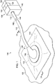
- FIGURE 1 is a perspective view illustrating a system 100 for treating a tissue site 102 on a patient with reduced pressure.
- the system 100 may include a dressing 106 for supplying reduced pressure to the tissue site 102.
- the dressing 106 may be disposed proximate to the tissue site 102.
- the system 100 also includes a treatment unit 108 and a conduit 110 fluidly connected between the dressing 106 and the treatment unit 108.
- the treatment unit 108 may supply reduced pressure through the conduit 110 to the dressing 106 at the tissue site 102.
- the dressing 106 may further include a reduced-pressure interface, such as a connector 116, and a manifold 112 (see also FIGURES 2A, 2B , and 2C ) wherein the connector 116 fluidly couples the conduit 110 to the manifold 112 for distributing reduced pressure at the tissue site 102.
- the dressing 106 may also include a drape 114 for covering the tissue site 102 and providing a seal between the connector 116 and the manifold 112.
- the treatment unit 108 may include a liquid-collection chamber, or a collection canister, a reduced-pressure source 140, and an instrumentation unit 150.
- the reduced-pressure source 140 may be housed within or used in conjunction with the treatment unit 108.
- the reduced-pressure source 140 may be an electrically-driven vacuum pump.
- the reduced-pressure source 140 may be a manually-actuated or manually-charged pump that does not require electrical power.
- the reduced-pressure source 140 may be other types of reduced pressure pumps, or may be a wall suction port such as those available in hospitals and other medical facilities.
- the instrumentation unit 150 may be in fluid communication with the reduced-pressure source 140.
- the instrumentation unit 150 may include a microprocessor adapted to process pressure signals received by the conduit 110, monitor the pressure signals, and issue alerts according to a pre-determined pressure therapy for a patient.
- the pre-determined pressure therapy may include a pressure profile of desired target pressures to be provided to a patient over a time period.
- the pressure profile may include a set-up profile applying target pressures at the commencement of therapy treatments and a maintenance profile for applying target pressure during therapy.
- the instrumentation unit 150 may include sensors, processing units, alarm indicators, memory, databases, software, display units, and user interfaces that further facilitate the application of reduced pressure treatment to the tissue site 102.
- pressure sensors 151 located in the instrumentation unit 150 may be disposed at or near the reduced-pressure source 140.
- the pressure sensors 151 may be one or more transducers located in the connector 116.
- the pressure sensors 151 include an electrical interface (not shown) that provides the pressure signal measured at or near the reduced-pressure source 140.
- the pressure signal provides an indication of the pressure between the connector 116 and the manifold 112 as described in more detail below.
- the pressure sensors 151 may communicate with a processing unit, such as the instrumentation unit 150, that monitors and controls the reduced pressure that may be delivered by the reduced-pressure source 140.
- the pressure sensors 151 communicate with the instrumentation unit 150 to monitor whether the pressure signal may be following a pressure set-up profile.
- the pressure set-up profile may include an expected increase in the reduced pressure detected at the tissue site 102 following initial application of reduced pressure.
- the instrumentation unit 150 provides an indication that the pressure signal did not follow the pressure set-up profile within the predetermined time period.
- the indication may be in the form of a visual or audible alert or alarm.
- the instrumentation unit 150 may provide an indication that the pressure signal followed the pressure set-up profile. The indication that the pressure set-up profile has been followed may be different than the indication that the pressure set-up profile has not been followed.
- FIGURE 2A is a sectional view of a portion of the system 100 disposed at the tissue site 102 and illustrating additional details of the connector 116.
- the system 100 may be used for various different types of tissue sites 102.
- tissue site in this context broadly refers to a wound or defect located on or within tissue of a human, animal, or other organism, including but not limited to, bone tissue, adipose tissue, muscle tissue, neural tissue, dermal tissue, vascular tissue, connective tissue, cartilage, tendons, or ligaments.
- a wound may include chronic, acute, traumatic, subacute, and dehisced wounds, partial-thickness burns, ulcers (such as diabetic, pressure, or venous insufficiency ulcers), flaps, grafts, and fistulas, for example.
- tissue site may also refer to areas of tissue that are not necessarily wounded or defective, but are instead areas in which it may be desired to add or promote the growth of additional tissue. For example, reduced pressure may be used in certain tissue areas to grow additional tissue that may be harvested and transplanted to another tissue location.
- tissue site may also include incisions, such as a surgical incision.
- the tissue site 102 may include an epidermis 124, subcutaneous tissue 125, or other muscle tissue 127.
- the tissue site 102 may be surrounded by healthy or undamaged tissue, for example a portion of the epidermis 124 that may be undamaged.
- Treatment of the tissue site 102 may include removal of fluids, for example, exudates or ascites.
- the manifold 112 may be positioned proximate to the tissue site 102 such that the manifold 112 has a first surface that faces the tissue site 102 and a second surface that may be opposite the first surface. As described in more detail below, the second surface may have a first portion, such as covered portion 128, and a second portion, such as exposed portion 129.
- the term "manifold” as used herein generally refers to a substance or structure that may be provided to assist in applying reduced pressure to, delivering fluids to, or removing fluids from the tissue site 102.
- the manifold 112 may include a plurality of flow channels or pathways that distribute fluids provided to and removed from the tissue site 102.
- the flow channels or pathways may be interconnected to improve distribution of fluids provided to or removed from the tissue site 102.
- the manifold 112 may be a biocompatible material that may be capable of being placed in contact with the tissue site 102 and distributing reduced pressure to the tissue site 102.
- Examples of the manifold 112 may include, without limitation, devices that have structural elements arranged to form flow channels, such as, for example, cellular foam, open-cell foam, porous tissue collections, liquids, gels, and foams that include, or cure to include, flow channels.
- the manifold 112 may be porous and may be made from foam, gauze, felted mat, or other material suited to a particular biological application.
- the manifold 112 may be a porous foam and may include a plurality of interconnected cells or pores that act as flow channels.
- the porous foam may be a polyurethane, open-cell, reticulated foam such as GranuFoam ® material manufactured by Kinetic Concepts, Incorporated of San Antonio, Texas.
- the manifold 112 may also be used to distribute fluids such as medications, antibacterials, growth factors, and other solutions to the tissue site 102.
- Other layers may be included in or on the manifold 112, such as absorptive materials, wicking materials, hydrophobic materials, and hydrophilic materials.
- the manifold 112 may be constructed from bioresorbable materials that do not have to be removed from the tissue site 102 following use of the system 100.
- Suitable bioresorbable materials may include, without limitation, a polymeric blend of polylactic acid (PLA) and polyglycolic acid (PGA).
- the polymeric blend may also include without limitation polycarbonates, polyfumarates, and capralactones.
- the manifold 112 may further serve as a scaffold for new cell-growth, or a scaffold material may be used in conjunction with the manifold 112 to promote cell-growth.
- a scaffold may be a substance or structure used to enhance or promote the growth of cells or formation of tissue, such as a three-dimensional porous structure that provides a template for cell growth.
- Illustrative examples of scaffold materials include calcium phosphate, collagen, PLA/PGA, coral hydroxy apatites, carbonates, or processed allograft materials.
- the drape 114 has a first side 134 and a second side 136 partially covering the surface portion 128 of the manifold 112 when positioned over the tissue site 102, and a drape aperture 115 extending through the drape 114, creating the exposed portion 129 and the covered portion 128 of the second surface of the manifold 112.
- the drape 114 may be a material that provides a fluid seal. "Fluid seal,” or “seal,” means a seal adequate to maintain reduced pressure at a desired site given the particular reduced-pressure source or subsystem involved.
- the drape 114 may be, for example, an impermeable or semi-permeable, elastomeric material.
- “Elastomeric” means having the properties of an elastomer.
- Elastomer generally refers to a polymeric material that may have rubber-like properties. More specifically, most elastomers may have ultimate elongations greater than 100% and a significant amount of resilience. The resilience of a material refers to the material's ability to recover from an elastic deformation. Elastomers that are relatively less resilient may also be used as these elastomers may be more likely to tear when faced with a cutting element.
- elastomers may include, but are not limited to, natural rubbers, polyisoprene, styrene butadiene rubber, chloroprene rubber, polybutadiene, nitrile rubber, butyl rubber, ethylene propylene rubber, ethylene propylene diene monomer, chlorosulfonated polyethylene, polysulfide rubber, polyurethane (PU), EVA film, co-polyester, and silicones.
- materials of the drape 114 may include a silicone drape, 3M Tegaderm ® drape, and a polyurethane (PU) drape such as one available from Avery Dennison Corporation of Pasadena, California.
- An additional, specific non-limiting example of a material of the drape 114 may include a 30 ⁇ m matt polyurethane film such as the Inspire TM 2317 manufactured by Exopack TM Advanced Coatings of Matthews, North Carolina.
- a drape adhesive 138 may be positioned between the second side 136 of the drape 114 and a portion of the epidermis 124 surrounding the tissue site 102 that may be intact.
- the drape adhesive 138 may hold the drape 114 in place and may aid the drape 114 to maintain reduced pressure in a sealed space 132 by fluidly sealing the drape 114 to the epidermis 124 surrounding the tissue site 102.
- Fluidly sealing the drape 114 to the epidermis 124 may refer to sealing of the drape 114 to the epidermis 124 so that fluid may be inhibited from passing between the drape 114 and the epidermis 124.
- the drape adhesive 138 may include another layer such as, for example, a gasket or additional sealing member.
- the drape adhesive 138 may take numerous forms.
- the drape adhesive 138 may be a medically acceptable adhesive, such as a pressure-sensitive adhesive, that extends about a portion of, a periphery of, or about all of the drape 114; a double-sided drape tape; a paste; a hydrocolloid; a hydro-gel; a silicone gel; an organogel; or other sealing devices or elements.
- the drape adhesive 138 may also be a sealing ring or other device.
- the drape adhesive 138 may be a releasable adhesive material capable of being removed from the tissue site 102 and reapplied to the tissue site 102.
- the drape adhesive 138 may be disposed on the second side 136 of the drape 114. Before use, the drape adhesive 138 may be covered by a release liner (not shown) to protect the attachment material 138 before being applied to the tissue site 102.
- the connector 116 may include a base 160 and a connector body 162 having a cavity 164.
- the base 160 may be coupled to one end of the connector body 162, extending from a peripheral portion of the connector body 162.
- the base 160 may be adjacent a portion of the cavity 164.
- the connector 116 may further include a cavity aperture 166 at one end of the connector body 162.
- the cavity aperture 166 may be formed through or part of the base 160.
- a conduit port 168 may be coupled to the other end of the connector body 162.
- the conduit port 168 may extend from the connector body 162 as shown in Figure 2A .
- the conduit port 168 may be fluidly coupled to the cavity 164.
- the conduit port 168 may include an aperture 170 for receiving a conduit, such as the conduit 110.
- the base 160 may be positioned adjacent the first side 134 of the drape 114 over the manifold 112 so that the cavity 164 is fluidly coupled to the exposed portion 129 of the manifold 112 through the drape aperture 115 of the drape 114.
- the base 160 may be coupled to the first side 134 of the drape 114 by a base adhesive 152 that holds the connector 116 in place on the drape 114.
- the base adhesive 152 may be similar to the drape adhesive 138. In some embodiments, the base adhesive 152 may have releasable characteristics allowing for the connector 116 to be removed from and reapplied to the drape 114.
- Coupled includes coupling via a separate object and includes direct coupling.
- the term “coupled” also encompasses two or more components that are continuous with one another by virtue of each of the components being formed from the same piece of material.
- the term “coupled” may include chemical, such as via a chemical bond, mechanical, thermal, or electrical coupling.
- Fluid coupling may mean that fluid may be in communication between the designated parts or locations.
- Pneumatic coupling may mean, in part, that gas or gas pressure may be in communication between the designated parts or locations.
- the conduit 110 may be a multi-lumen conduit having a primary lumen 142 and a secondary lumen 144.
- the conduit 110 may have different shapes and include more or fewer primary lumens 142 and secondary lumens 144.
- the primary lumen 142 may deliver reduced pressure, and the secondary lumen 144 may function as a sensing lumen.
- the primary lumen 142 and the secondary lumen 144 may be in fluid communication with the cavity 164.
- the secondary lumen 144 may be configured to be fluidly isolated from the primary lumen 142 so as not to interfere with the process of sensing the pressure.
- Liquids or exudates communicated through the primary lumen 142 may be removed from the conduit 110 and may be retained within a liquid-collection chamber (not shown) fluidly coupled to the conduit 110.
- the secondary lumen 144 may fluidly communicate pressure at a terminal end of the conduit 110 within the connector 116 to the pressure sensors 151. The pressure communicated by the secondary lumen 144 may be representative of the pressure at the tissue site 102.
- the connector 116 may be a T.R.A.C. ® Pad or Sensa T.R.A.C. ® Pad available from KCI of San Antonio, Texas, modified as described in more detail below.
- the connector 116 may fluidly couple the reduced pressure provided by the primary lumen 142 to the manifold 112 through the drape aperture 115 of the drape 114.
- the manifold 112 may distribute the reduced pressure to the sealed space 132 formed by the drape 114 and the tissue site 102.
- the connector 116 allows reduced pressure to be delivered to the tissue site 102.
- the reduced pressure may be between -5 mm Hg (-667 Pa) and - 500 mm Hg (-66.7 kPa) and between -75 mm Hg (-9.9 kPa) and -300 mm Hg (-39.9 kPa).
- the reduced pressure connector 116 may be made of a semi-rigid material that may be capable of collapsing under a force.
- the connector 116 may be made from a plasticized polyvinyl chloride (PVC), polyurethane, cyclic olefin copolymer elastomer, thermoplastic elastomer, poly acrylic, silicone polymer, or polyether block amide copolymer.
- PVC polyvinyl chloride
- the reduced pressure connector 116 may be formed of a semi-rigid material that collapses when under reduced pressure less than a threshold pressure.
- FIGURE 2B is a bottom perspective view of the connector 116 illustrating additional details that may be associated with some embodiments.
- the connector 116 may include one or more channels 165 formed on portions of the inside surfaces of the connector body 162 within the cavity 164.
- the channels 165 may extend between the base 160 and the conduit port 168.
- the channels 165 may direct the flow of fluids and exudates from the tissue site 102 and the manifold 112 to the conduit port 168 and into the primary lumen 142, which returns the fluids to the treatment unit 108 for storage or disposal.
- the primary lumen 142 may be fluidly coupled to the manifold 112 by the cavity 164 of the connector 116 through the drape aperture 115 of the drape 114.
- the drape aperture 115 may be approximately the same size as the cavity aperture 166 of the cavity 164 to facilitate fluid communication between the primary lumen 142 and the manifold 112.
- the drape 114 may come with the drape aperture 115 preformed.
- the drape aperture 115 is formed prior to the drape 114 being applied to the tissue site 102. If the drape aperture 115 of the drape 114 may be too small, fluid flow between the manifold 112 and the connector 116 may be partially or fully blocked.
- the reduced pressure provided by the primary lumen 142 may not be pneumatically coupled to the tissue site 102. Additionally, if the drape aperture 115 of the drape 114 is properly sized, the cavity aperture 166 should be concentrically aligned with the drape aperture 115 when the base 160 is coupled to the drape 114. If the cavity aperture 166 is misaligned with the drape aperture 115, fluid flow between the manifold 112 and the connector 116 may be partially or fully blocked. If fluid flow is partially or fully blocked, the reduced pressure provided by the primary lumen 142 may not pneumatically coupled to the tissue site 102. If the primary lumen 142 is not pneumatically coupled to the tissue site 102, the system 100 may provide no reduced-pressure therapy or inadequate reduced-pressure therapy.
- the secondary lumen 144 may be fluidly coupled to the cavity 164 of the connector 116. If the "blockage conditions" previously described occur, the primary lumen 142 may become pneumatically coupled to the secondary lumen 144 rather than to the manifold 112 and the tissue site 102. If the primary lumen 142 and the secondary lumen 144 are pneumatically coupled, the secondary lumen 144 may provide the pressure sensors 151 with a pressure indicating that the tissue site 102 has reached the desired target pressure. Even though the reduced pressure is not being supplied to the tissue site 102, the reduced pressure may be supplied to the cavity 164, and the pressure sensors 151 may be measuring the pressure in the cavity 164 via the secondary lumen 144.
- the drape 114 may be removed, and the drape aperture 115 may be resized or the connector 116 may be repositioned to allow fluid flow between the cavity 164 and the sealed space 132. It may be desirable to correct these blockage conditions during the setup procedures before commencing therapeutic treatments. Thus, it may be desirable that the drape adhesive 138 and the base adhesive 152 be releasable so that both the drape 114 and the connector 116 can be reapplied after the blockage condition is corrected.
- the connector 116 may also include a sensing probe 180.
- the sensing probe 180 may be fluidly coupled between the secondary lumen 144 and the exposed surface 129 of the manifold 112.
- the sensing probe 180 may have a probe lumen 186.
- the probe lumen 186 may have an aperture at each end of the sensing probe 180.
- the sensing probe 180 may have a proximal end 182 configured to be positioned adjacent to the secondary lumen 144 of the conduit 110.
- the sensing probe 180 may also have a distal end 184 extending into the cavity 164 of the connector body 162. The distal end 184 may be configured to be positioned adjacent the exposed surface 129 of the manifold 112.
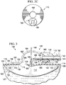
- FIGURE 2C is a sectional view of a portion of the connector 116 taken along line 2C-2C of FIGURE 2A , illustrating additional details that may be associated with some embodiments.
- the secondary lumen 144 may fluidly couple to the probe lumen 186 so that a fluid path provided by the secondary lumen 144 may extend past a terminus of the primary lumen 142 through the probe lumen 186.
- the aperture of the probe lumen 186 of the distal end 184 of the sensing probe 180 may extend from the cavity 164 to a plane occupied by the base 160.
- the aperture of the probe lumen 186 of the distal end 184 of the sensing probe 180 may extend from the cavity 164 past the plane occupied by the base 160.
- the aperture of the probe lumen 186 of the distal end 184 of the sensing probe 180 may be proximate to or in contact with the manifold 112.
- the probe lumen 186 may fluidly couple the secondary lumen 144 to the manifold 112 rather than to the cavity 164 of the connector body 162.
- the probe lumen 186 pneumatically separates the primary lumen 142 and the secondary lumen 144 to minimize the risk of pressure readings that may not be not representative of pressure in the sealed space 132.
- the secondary lumen 144 and the primary lumen 142 may be pneumatically coupled when the sealed space 132 is open to allow fluid communication between the primary lumen 142, the sealed space 132 occupied by the manifold 112, and the secondary lumen 144.
- the connector 116 may be coupled to the drape 114 so that the distal end 184 of the sensing probe 180 is aligned with a medial portion of the drape aperture 115 of the drape 114.
- the distal end 184 of the sensing probe 180 may contact the exposed portion 129 of the manifold 112.
- the sensing probe 180 includes an elbow 188 that may be configured to position the distal end 184 of the sensing probe 180 proximate to the plane occupied by the base 160.
- the elbow 188 may turn the sensing probe 180 so that the distal end 184 is located in a plane that forms an angle with a plane occupied by the proximal end 182.
- the elbow 188 may be a 90° elbow.
- the elbow 188 may have a radius of curvature between about 30° and about 120°.
- the primary lumen 142 may supply the reduced pressure to the cavity 164 and to the manifold 112 through the drape aperture 115 of the drape 114.
- the reduced pressure supplied to the cavity 164 and the manifold 112 may draw fluids from the tissue site 102 through the manifold 112 and into the cavity 164 where the primary lumen 142 may conduct the fluids away from the tissue site 102 for disposal.
- the supply of reduced pressure to the cavity 164 may also be pneumatically coupled to the probe lumen 186 through the manifold 112.
- the instrumentation unit 150 may identify that the primary lumen 142 and the secondary lumen 144 are pneumatically coupled through the manifold 112 and the probe lumen 186 in response to the pressure signal from the pressure sensors 151.
- the pressure at exposed portion 129 of the manifold 112 may be pneumatically communicated through the probe lumen 186 and the secondary lumen 144 to the pressure sensors 151.
- the sensing probe 180 can aid in determining whether the system 100 may be operating properly to supply reduced pressure to the tissue site 102.
- the sensing probe 180 may aid in placement of the connector 116 by acting as a visual guide for alignment of the connector 116 relative to the drape aperture 115 of the drape 114.
- the distal end 184 of the sensing probe 180 may be aligned with a medial portion of the drape aperture 115 to concentrically align the cavity aperture 166 with the drape aperture 115.
- the manifold 112 may filter fluids away from the distal end 184 of the sensing probe 180 to prevent entry of fluid from the tissue site 102 into the probe lumen 186 and the secondary lumen 144.
- FIGURE 3 is a side sectional view of the dressing 106 disposed at the tissue site 102, illustrating additional details of the connector 116 in a first failure mode.
- the dimensions of the drape aperture 115 may be larger than a dimension of the distal end 184 of the sensing probe 180.
- the dimensions of the drape aperture 115 may also be smaller than a dimension of the cavity aperture 166.
- the drape aperture 115, the distal end 184, and the cavity aperture 166 may all be substantially circular.
- the drape aperture 115 may have a circumference that may be larger than a circumference of the distal end 184 but smaller than a circumference of the cavity aperture 166.
- the distal end 184 may not be aligned with a medial portion of the drape aperture 115. Consequently, when the connector 116 is secured to the drape 114, a portion of the drape 114 may be disposed between the distal end 184 of the sensing probe 180 and the manifold 112. The portion of the drape 114 may block or partially block the cavity aperture 166.
- the portion of the drape 114 between the distal end 184 of the sensing probe 180 and the manifold 112 may block fluid communication with the probe lumen 186.
- the secondary lumen 144 may not be pneumatically coupled to the primary lumen 142 through the sensing probe 180.
- the instrumentation unit 150 ( FIGURE 1 ) may detect the failure of the primary lumen 142 and the secondary lumen 144 to pneumatically couple with the pressure sensors 151, and the instrumentation unit 150 may provide an indication or error message near the start of the application of reduced pressure.
- the drape aperture 115 is smaller than the cavity aperture 166, the tissue site 102 may receive a reduced pressure that may be less than the desired reduced pressure for reduced-pressure therapy.
- FIGURE 4 is a side sectional view of a portion of the system 100 disposed at the tissue site 102, illustrating additional details of the connector 116 in a second failure mode of the system 100.
- the drape aperture 115 was not formed in the drape 114. Consequently, when the connector 116 is secured to the drape 114, the drape 114 may block fluid communication between the cavity aperture 166 and the manifold 112. In addition, the drape 114 may block fluid communication between the probe lumen 186 and the manifold 112. If the reduced pressure is supplied through the primary lumen 142, the portion of the drape 114 between the distal end 184 of the probe lumen 186 and the manifold 112 may be drawn into contact with the distal end 184.
- the instrumentation unit 150 may then provide an indication or error message that no pneumatic coupling has occurred. During the second failure mode of the system 100, no reduced pressure may be supplied to the tissue site 102.
- FIGURE 5 is a side sectional view of a portion of the system 100 disposed at the tissue site 102, illustrating additional details of the connector 116 in a third failure mode.
- a dimension of the drape aperture 115 may be larger than a dimension of the distal end 184 of the sensing probe 180.
- the dimension of the drape aperture 115 may also be smaller than a dimension of the cavity aperture 166.
- the drape aperture 115, the distal end 184, and the cavity aperture 166 may all be substantially circular.
- the drape aperture 115 may have a circumference that may be larger than a circumference of the distal end 184 but smaller than a circumference of the cavity aperture 166.
- the distal end 184 may be aligned with a medial portion of the drape aperture 115. Consequently, when the connector 116 is secured to the drape 114, the distal end 184 of the sensing probe 180 may contact the exposed portion 129 of the manifold 112. A portion of the drape 114 may block or partially block the cavity aperture 166. If reduced pressure is supplied through the primary lumen 142, the drape 114 may prevent fluid communication of the reduced pressure to the manifold 112. The probe lumen 186, being in fluid communication with the manifold 112 through the drape aperture 115, may not be in fluid communication with the cavity 164 because the cavity aperture 166 is blocked by the portion of the drape 114.
- the primary lumen 142 and the secondary lumen 144 may not be pneumatically coupled by the probe lumen 186.
- the probe lumen 186 and the secondary lumen 144 may not communicate a reduced pressure to the sensors 151 that indicates that reduced-pressure is being provided to the sealed space 132.
- the primary lumen 142 and the secondary lumen 144 may pneumatically couple through the sensing probe 180, but reduced pressure communicated by the probe lumen 186 and the secondary lumen 144 may not be the expected pressure for the proper application of reduced-pressure therapy.
- the instrumentation unit 150 may detect this pressure signal and provide an error indication as a result.
- the base adhesive 152 may be a releasable adhesive allowing removal of the connector 116. If the drape aperture 115 is improperly formed, the connector 116 may be de-coupled from the drape 114 and the drape aperture 115 may be formed to the suitable size and shape, for example, to have a size and shape similar to the size and shape of the cavity aperture 166. The connector 116 may then be re-coupled to the drape 114 so that the distal end 184 may be aligned with a medial portion of the drape aperture 115. Reduced pressure may then be reapplied to the connector 116 through the conduit 110.
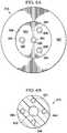
- FIGURE 6A is a bottom view of an alternative connector 616
- FIGURE 6B is a sectional view through an alternative conduit 610.
- Connector 616 may be similar to connector 116 described above and modified as described in more detail below.
- the connector 616 includes a connector body having a cavity 664 including a cavity aperture 666 at one end of the connector body, a conduit port extending from the other end of the connector body and fluidly coupled to the cavity 664, and a base 660 extending from a peripheral portion of the connector body adjacent the cavity aperture 666.
- the conduit port includes an aperture for receiving the conduit 610.
- the connector body, the cavity 664, the cavity aperture 666, the conduit port, the aperture, and the base 660 may be structurally and operationally similar to the connector body 162, the cavity 164, the cavity aperture 166, the conduit port 168, the aperture 170, and the base 160 described above with respect to FIGURES 2A-2C .
- the connector 616 includes one or more sensing probes having distal ends 684 and probe lumens 686.
- the sensing probes, the distal ends 684, and the probe lumens 686 may be similar to the sensing probe 180 and the distal end 184 described above with respect to FIGURES 2A-2C .
- the connector 616 includes four sensing probes having distal ends 684 and probe lumens 686. Each sensing probe may be structurally modified so that each distal end 684 may be disposed at separate locations of cavity aperture 666.
- a distal end 684 may be positioned proximate to a medial portion of cavity aperture 666, and each of the other three distal ends 684 may be equidistantly distributed relative to the medial portion of cavity aperture 666.
- Each sensing probe associated with a respective distal end 684 may be modified so that the distal end 684 may be disposed at the desired location.
- the conduit 610 may include a primary lumen 642 and one or more secondary lumens 644. In the illustrated embodiment, four secondary lumens 644 are shown.
- the primary lumen 642 and the secondary lumens 644 may be structurally and operationally similar to the primary lumen 142 and the secondary lumen 144 of FIGURE 2C .
- the primary lumen 642 may be fluidly coupled to the cavity 664, and each secondary lumen 644 may be fluidly coupled to a separate probe lumen 686. Inclusion of the additional sensing probes provides additional redundancy for the connector 616.
- the additional sensing probes may allow the pressure sensors 151 of the treatment unit 150 to determine the misalignment by identifying a particular sensing probe where the communicated pressure differs from the expected pressure.
- FIGURE 7 illustrates a high-level flow chart 700 that depicts logical operational steps performed by, for example, the system 100 of FIGURE 1 , which may be implemented in accordance with an embodiment.
- the process begins, wherein the system 100 disposes a distribution manifold proximate to the tissue site.
- the manifold 112 may be disposed proximate to the tissue site 102.
- an aperture may be formed in a sealing member.
- the drape aperture 115 may be formed in the drape 114, the drape aperture 115 having a size and shape substantially similar to the size and shape of the cavity aperture 166.
- the system 100 covers the manifold and a portion of the epidermis surrounding the tissue site that may be intact with a drape to form a sealed space.
- the manifold 112 and a portion of the epidermis 124 surrounding the tissue site 102 that may be intact may be covered with the drape 114 to form the sealed space 132.
- the system 100 provides a reduced-pressure source; for example, the system 100 provides the treatment unit 108 having the reduced-pressure source 140.
- the system couples a connector proximate to the first side of the sealing member, and at block 711 couples a conduit between the reduced-pressure source and the connector.
- the connector 116 may be coupled to the drape 114 so that the distal end 184 of the sensing probe 180 may be proximate to a medial portion of the drape aperture 115 of the drape 114 and adjacent to the exposed surface 129 of the manifold 112.
- the conduit 110 may be coupled between the connector 116 and the treatment unit 108.
- the system 100 supplies reduced pressure to a cavity of the connector and pneumatically couples the cavity to a sensing probe of the connector.
- the treatment unit 108 supplies reduced pressure to the connector 116 through the conduit 110 and pneumatically couples the cavity 164 of the connector 116 to the sensing probe 180 of the connector 116.
- the system 100 continues to block 717, where the system 100 provides an indication that the cavity did not pneumatically couple to the sensing probe.
- the treatment unit 108 may provide an indication that pneumatic coupling did not occur.
- the system 100 continues to block 719, where the system 100 continues to supply reduced pressure to the reduced pressure interface.
- the treatment unit 108 may continue to provide reduced pressure to the connector 116.
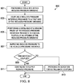
- FIGURE 8 illustrates a high-level flow chart 800 that depicts logical operational steps performed by, for example, the system 100 of FIGURE 1 , which may be implemented in accordance with an embodiment.
- the process begins, wherein the system 100 prepares a tissue site with a reduced-pressure dressing.
- the tissue site 102 may be prepared with the dressing 106.
- the system 100 couples a connector proximate to the first side of the dressing 106, and at block 805 positions a distal end of a sensing probe of the connector proximate to a medial portion of an aperture of the reduced-pressure dressing.
- the connector 116 may be coupled to the drape 114 of the dressing 106, and the distal end 184 of the sensing probe 180 may be positioned proximate to a medial portion of the drape aperture 115 of the drape 114 of the dressing 106.
- system 100 supplies reduced pressure to the connector to pneumatically couple the supply of reduced pressure to the sensing probe of the connector.
- the treatment unit 108 supplies reduced pressure to the connector 116 through the conduit 110 to pneumatically couple the cavity 164 of the connector 116 with the sensing probe 180 of the connector 116.
- the system 100 determines whether pneumatic coupling occurs, and in the event that pneumatic coupling does occur, the system 100 continues to block 811, where the system 100 continues to supply reduced pressure to the reduced pressure interface. For example, the treatment unit 108 may continue to provide reduced pressure to the connector 116 As indicated at decision block 809, in the event that pneumatic coupling does not occur, the system 100 continues to block 813, where the system 100 indicates failure to pneumatically couple. For example, the treatment unit 108 may provide an indication that pneumatic coupling did not occur.
- the reduced-pressure treatment apparatus, system, and method may provide notification of improper application of reduced-pressure to a tissue site.
- the reduced-pressure treatment system may provide notification of improper formation of an aperture in a dressing that may prevent proper application of reduced pressure.
- the reduced-pressure treatment system may provide notification of incorrect placement of a connector relative to the dressing.
- the reduced-pressure treatment system may also provide notification that an aperture through the dressing may not be of sufficient size.
Description
- The present disclosure relates generally to medical treatment systems and, more particularly, but not by way of limitation, to an apparatus, system, and method for treating a tissue site with reduced pressure involving a reduced-pressure interface.
- Clinical studies and practice have shown that providing a reduced pressure in proximity to a tissue site augments and accelerates the growth of new tissue at the tissue site. The applications of this phenomenon are numerous, but application of reduced pressure has been particularly successful in treating wounds. This treatment (frequently referred to in the medical community as "negative pressure wound therapy," "reduced pressure therapy," or "vacuum therapy") provides a number of benefits, which may include faster healing and increased formulation of granulation tissue. Typically, reduced pressure is applied to the tissue site through a dressing that may include a manifold device such as a porous pad covered
- by a drape to maintain the reduced pressure within the wound. The porous pad contains cells or pores and distributes reduced pressure to the tissue site and channels fluids that are drawn from the tissue site. In order for the patient to receive the benefits of the reduced pressure therapy, the reduced pressure must be correctly supplied to the manifold device. During some treatments, a caregiver preparing the reduced pressure treatment may improperly apply the dressings over the wound so that the reduced pressure is not properly applied to the manifold device. Therefore, there is a need for a system, method, and apparatus that provides
- notification to the caregiver of improper administration of reduced pressure.
-
US2012/0123358 discloses a system for monitoring pressure at a plurality of tissue sites using a plurality of sensing lumens. -
WO2012/057881 discloses a system for providing reduced pressure to a tissue site utilizing wireless power systems. -
US2011/0178481 discloses connection pads for coupling reduced pressure to a wound and for monitoring reduced pressure at a wound. -
US2012/0016324 discloses a conduit housing having a dividing wall for providing reduced pressure delivery and sensing regions. -
WO2009/016605 discloses a wound cover for reduced pressure therapy with separate reduced pressure delivery and sensing conduits. -
DE 10 2009 039336 discloses a connector for a reduced pressure treatment system including a pressure sensor. - Insofar as the term invention or embodiment is used in the following, or features are presented as being optional, this should be interpreted in such a way that the only protection sought is that of the invention claimed.
- Reference(s) to "embodiment(s)" throughout the description which are not under the scope of the appended claims merely represent possible exemplary executions and are not part of the present invention.
- There is provided a connector for fluidly coupling a conduit and a manifold of a reduced-pressure treatment system according to any preceding claim, the connector comprising: a connector body having a cavity including a cavity aperture at a first end of the connector body; a conduit port extending from a second end of the connector body and configured to fluidly couple an end of a primary lumen of the conduit to the cavity and to fluidly couple an end of at least one secondary lumen of the conduit to the connector body; a base extending from a peripheral portion of the connector body adjacent to the cavity aperture and configured to be positioned adjacent to a first surface of a drape covering the manifold, wherein the first surface faces away from the manifold, wherein the cavity is configured to be fluidly coupled to the manifold through an aperture formed in the drape; and a sensing probe having a proximal end configured to be fluidly coupled to the at least one secondary lumen and a distal end extending to the cavity aperture, wherein the distal end is configured to be positioned adjacent to and in fluid communication with the manifold, wherein the distal end of the sensing probe extends from the cavity past a plane occupied by the base.
- A selection of optional features is set out in the dependent claims.
- Illustrative embodiments are described in more detail below with reference to the attached figures, which are incorporated by reference herein and wherein:
-
FIG. 1 is a perspective view of a system for treating a tissue site on a patient with reduced pressure in accordance with an embodiment; -
FIG. 2A is a cross-sectional view of a reduced-pressure interface of the system ofFIGURE 1 , taken alongline 2A-2A in accordance with an embodiment; -
FIGURE 2B is a perspective bottom view of the reduced-pressure interface ofFIGURE 2A illustrating additional details of the reduced-pressure interface in accordance with an embodiment; -
FIG. 2C is a cross-sectional view of a portion of the reduced-pressure interface ofFIGURE 2A taken alongline 2C—2C in accordance with an embodiment; -
FIGURE 3 is a cross-sectional view of the reduced-pressure interface ofFIGURE 2A in a first failure mode in accordance with an embodiment; -
FIGURE 4 is a cross-sectional view of the reduced-pressure interface ofFIGURE 2A in a second failure mode in accordance with an embodiment; -
FIGURE 5 is a cross-sectional view of the reduced-pressure interface ofFIGURE 2A in a third failure mode in accordance with an embodiment; -
FIGURE 6A is a bottom view of another reduced-pressure interface in accordance with an embodiment; -
FIGURE 6B is a cross-sectional view of another illustrative conduit that may be used with the system ofFIGURE 1 in accordance with an embodiment; -
FIGURE 7 is a high-level flow chart depicting operational steps of a method for using the system ofFIGURE 1 in accordance with an embodiment; and -
FIGURE 8 is a high-level flow chart depicting operational steps of a method for using the system ofFIGURE 1 in accordance with an embodiment. - New and useful apparatuses associated with reduced pressure interfaces used for regulating pressure are set forth in the appended claims. Objectives, advantages, and a preferred mode of making and using apparatuses may be understood best by reference to the following detailed description in conjunction with the accompanying drawings.
- The term "reduced pressure" as used herein generally refers to a pressure less than the ambient pressure at a tissue site that is being subjected to treatment. In most cases, this reduced pressure will be less than the atmospheric pressure at which the patient is located. Alternatively, the reduced pressure may be less than a hydrostatic pressure associated with tissue at the tissue site. Unless otherwise indicated, values of pressure stated herein are gauge pressures. References to increases in reduced pressure typically refer to a decrease in absolute pressure, and decreases in reduced pressure typically refer to an increase in absolute pressure.
-
FIGURE 1 is a perspective view illustrating asystem 100 for treating atissue site 102 on a patient with reduced pressure. Thesystem 100 may include adressing 106 for supplying reduced pressure to thetissue site 102. Thedressing 106 may be disposed proximate to thetissue site 102. Thesystem 100 also includes atreatment unit 108 and aconduit 110 fluidly connected between thedressing 106 and thetreatment unit 108. Thetreatment unit 108 may supply reduced pressure through theconduit 110 to thedressing 106 at thetissue site 102. In an illustrative embodiment, thedressing 106 may further include a reduced-pressure interface, such as aconnector 116, and a manifold 112 (see alsoFIGURES 2A, 2B , and2C ) wherein theconnector 116 fluidly couples theconduit 110 to themanifold 112 for distributing reduced pressure at thetissue site 102. Thedressing 106 may also include adrape 114 for covering thetissue site 102 and providing a seal between theconnector 116 and themanifold 112. - The
treatment unit 108 may include a liquid-collection chamber, or a collection canister, a reduced-pressure source 140, and aninstrumentation unit 150. The reduced-pressure source 140 may be housed within or used in conjunction with thetreatment unit 108. In an illustrative embodiment, the reduced-pressure source 140 may be an electrically-driven vacuum pump. In another illustrative embodiment, the reduced-pressure source 140 may be a manually-actuated or manually-charged pump that does not require electrical power. The reduced-pressure source 140 may be other types of reduced pressure pumps, or may be a wall suction port such as those available in hospitals and other medical facilities. - The
instrumentation unit 150 may be in fluid communication with the reduced-pressure source 140. Theinstrumentation unit 150 may include a microprocessor adapted to process pressure signals received by theconduit 110, monitor the pressure signals, and issue alerts according to a pre-determined pressure therapy for a patient. The pre-determined pressure therapy may include a pressure profile of desired target pressures to be provided to a patient over a time period. The pressure profile may include a set-up profile applying target pressures at the commencement of therapy treatments and a maintenance profile for applying target pressure during therapy. Theinstrumentation unit 150 may include sensors, processing units, alarm indicators, memory, databases, software, display units, and user interfaces that further facilitate the application of reduced pressure treatment to thetissue site 102. - In one illustrative embodiment,
pressure sensors 151 located in theinstrumentation unit 150 may be disposed at or near the reduced-pressure source 140. In another illustrative embodiment, thepressure sensors 151 may be one or more transducers located in theconnector 116. Thepressure sensors 151 include an electrical interface (not shown) that provides the pressure signal measured at or near the reduced-pressure source 140. The pressure signal provides an indication of the pressure between theconnector 116 and the manifold 112 as described in more detail below. Thepressure sensors 151 may communicate with a processing unit, such as theinstrumentation unit 150, that monitors and controls the reduced pressure that may be delivered by the reduced-pressure source 140. In an illustrative embodiment, thepressure sensors 151 communicate with theinstrumentation unit 150 to monitor whether the pressure signal may be following a pressure set-up profile. The pressure set-up profile may include an expected increase in the reduced pressure detected at thetissue site 102 following initial application of reduced pressure. In the event the pressure signal does not follow the pressure set-up profile within a predetermined time period, theinstrumentation unit 150 provides an indication that the pressure signal did not follow the pressure set-up profile within the predetermined time period. In an illustrative example, the indication may be in the form of a visual or audible alert or alarm. In the event the pressure signal is following the pressure set-up profile, theinstrumentation unit 150 may provide an indication that the pressure signal followed the pressure set-up profile. The indication that the pressure set-up profile has been followed may be different than the indication that the pressure set-up profile has not been followed. -
FIGURE 2A is a sectional view of a portion of thesystem 100 disposed at thetissue site 102 and illustrating additional details of theconnector 116. Thesystem 100 may be used for various different types oftissue sites 102. The term "tissue site" in this context broadly refers to a wound or defect located on or within tissue of a human, animal, or other organism, including but not limited to, bone tissue, adipose tissue, muscle tissue, neural tissue, dermal tissue, vascular tissue, connective tissue, cartilage, tendons, or ligaments. A wound may include chronic, acute, traumatic, subacute, and dehisced wounds, partial-thickness burns, ulcers (such as diabetic, pressure, or venous insufficiency ulcers), flaps, grafts, and fistulas, for example. The term "tissue site" may also refer to areas of tissue that are not necessarily wounded or defective, but are instead areas in which it may be desired to add or promote the growth of additional tissue. For example, reduced pressure may be used in certain tissue areas to grow additional tissue that may be harvested and transplanted to another tissue location. The term "tissue site" may also include incisions, such as a surgical incision. Thetissue site 102, may include anepidermis 124,subcutaneous tissue 125, orother muscle tissue 127. Thetissue site 102 may be surrounded by healthy or undamaged tissue, for example a portion of theepidermis 124 that may be undamaged. Treatment of thetissue site 102 may include removal of fluids, for example, exudates or ascites. - In the illustrated embodiment, the manifold 112 may be positioned proximate to the
tissue site 102 such that the manifold 112 has a first surface that faces thetissue site 102 and a second surface that may be opposite the first surface. As described in more detail below, the second surface may have a first portion, such as coveredportion 128, and a second portion, such as exposedportion 129. The term "manifold" as used herein generally refers to a substance or structure that may be provided to assist in applying reduced pressure to, delivering fluids to, or removing fluids from thetissue site 102. The manifold 112 may include a plurality of flow channels or pathways that distribute fluids provided to and removed from thetissue site 102. In one illustrative embodiment, the flow channels or pathways may be interconnected to improve distribution of fluids provided to or removed from thetissue site 102. The manifold 112 may be a biocompatible material that may be capable of being placed in contact with thetissue site 102 and distributing reduced pressure to thetissue site 102. Examples of the manifold 112 may include, without limitation, devices that have structural elements arranged to form flow channels, such as, for example, cellular foam, open-cell foam, porous tissue collections, liquids, gels, and foams that include, or cure to include, flow channels. The manifold 112 may be porous and may be made from foam, gauze, felted mat, or other material suited to a particular biological application. In one embodiment, the manifold 112 may be a porous foam and may include a plurality of interconnected cells or pores that act as flow channels. The porous foam may be a polyurethane, open-cell, reticulated foam such as GranuFoam® material manufactured by Kinetic Concepts, Incorporated of San Antonio, Texas. In some embodiments, the manifold 112 may also be used to distribute fluids such as medications, antibacterials, growth factors, and other solutions to thetissue site 102. Other layers may be included in or on the manifold 112, such as absorptive materials, wicking materials, hydrophobic materials, and hydrophilic materials. - In one illustrative embodiment, the manifold 112 may be constructed from bioresorbable materials that do not have to be removed from the
tissue site 102 following use of thesystem 100. Suitable bioresorbable materials may include, without limitation, a polymeric blend of polylactic acid (PLA) and polyglycolic acid (PGA). The polymeric blend may also include without limitation polycarbonates, polyfumarates, and capralactones. The manifold 112 may further serve as a scaffold for new cell-growth, or a scaffold material may be used in conjunction with the manifold 112 to promote cell-growth. A scaffold may be a substance or structure used to enhance or promote the growth of cells or formation of tissue, such as a three-dimensional porous structure that provides a template for cell growth. Illustrative examples of scaffold materials include calcium phosphate, collagen, PLA/PGA, coral hydroxy apatites, carbonates, or processed allograft materials. - The
drape 114 has afirst side 134 and asecond side 136 partially covering thesurface portion 128 of the manifold 112 when positioned over thetissue site 102, and adrape aperture 115 extending through thedrape 114, creating the exposedportion 129 and the coveredportion 128 of the second surface of themanifold 112. Thedrape 114 may be a material that provides a fluid seal. "Fluid seal," or "seal," means a seal adequate to maintain reduced pressure at a desired site given the particular reduced-pressure source or subsystem involved. Thedrape 114 may be, for example, an impermeable or semi-permeable, elastomeric material. "Elastomeric" means having the properties of an elastomer. Elastomer generally refers to a polymeric material that may have rubber-like properties. More specifically, most elastomers may have ultimate elongations greater than 100% and a significant amount of resilience. The resilience of a material refers to the material's ability to recover from an elastic deformation. Elastomers that are relatively less resilient may also be used as these elastomers may be more likely to tear when faced with a cutting element. Examples of elastomers may include, but are not limited to, natural rubbers, polyisoprene, styrene butadiene rubber, chloroprene rubber, polybutadiene, nitrile rubber, butyl rubber, ethylene propylene rubber, ethylene propylene diene monomer, chlorosulfonated polyethylene, polysulfide rubber, polyurethane (PU), EVA film, co-polyester, and silicones. Additional, specific examples of materials of thedrape 114 may include a silicone drape, 3M Tegaderm® drape, and a polyurethane (PU) drape such as one available from Avery Dennison Corporation of Pasadena, California. An additional, specific non-limiting example of a material of thedrape 114 may include a 30µm matt polyurethane film such as the Inspire™ 2317 manufactured by Exopack™ Advanced Coatings of Matthews, North Carolina. - A drape adhesive 138 may be positioned between the
second side 136 of thedrape 114 and a portion of theepidermis 124 surrounding thetissue site 102 that may be intact. The drape adhesive 138 may hold thedrape 114 in place and may aid thedrape 114 to maintain reduced pressure in a sealedspace 132 by fluidly sealing thedrape 114 to theepidermis 124 surrounding thetissue site 102. Fluidly sealing thedrape 114 to theepidermis 124 may refer to sealing of thedrape 114 to theepidermis 124 so that fluid may be inhibited from passing between thedrape 114 and theepidermis 124. The drape adhesive 138 may include another layer such as, for example, a gasket or additional sealing member. The drape adhesive 138 may take numerous forms. For example, the drape adhesive 138 may be a medically acceptable adhesive, such as a pressure-sensitive adhesive, that extends about a portion of, a periphery of, or about all of thedrape 114; a double-sided drape tape; a paste; a hydrocolloid; a hydro-gel; a silicone gel; an organogel; or other sealing devices or elements. The drape adhesive 138 may also be a sealing ring or other device. In still another example, the drape adhesive 138 may be a releasable adhesive material capable of being removed from thetissue site 102 and reapplied to thetissue site 102. The drape adhesive 138 may be disposed on thesecond side 136 of thedrape 114. Before use, the drape adhesive 138 may be covered by a release liner (not shown) to protect theattachment material 138 before being applied to thetissue site 102. - The
connector 116 may include abase 160 and aconnector body 162 having acavity 164. In some embodiments, thebase 160 may be coupled to one end of theconnector body 162, extending from a peripheral portion of theconnector body 162. The base 160 may be adjacent a portion of thecavity 164. Theconnector 116 may further include acavity aperture 166 at one end of theconnector body 162. For example, thecavity aperture 166 may be formed through or part of thebase 160. Aconduit port 168 may be coupled to the other end of theconnector body 162. In some embodiments, for example, theconduit port 168 may extend from theconnector body 162 as shown inFigure 2A . Theconduit port 168 may be fluidly coupled to thecavity 164. Theconduit port 168 may include anaperture 170 for receiving a conduit, such as theconduit 110. When theconnector 116 is positioned at thetissue site 102, thebase 160 may be positioned adjacent thefirst side 134 of thedrape 114 over the manifold 112 so that thecavity 164 is fluidly coupled to the exposedportion 129 of the manifold 112 through thedrape aperture 115 of thedrape 114. The base 160 may be coupled to thefirst side 134 of thedrape 114 by a base adhesive 152 that holds theconnector 116 in place on thedrape 114. The base adhesive 152 may be similar to thedrape adhesive 138. In some embodiments, the base adhesive 152 may have releasable characteristics allowing for theconnector 116 to be removed from and reapplied to thedrape 114. - As used herein, the term "coupled" includes coupling via a separate object and includes direct coupling. The term "coupled" also encompasses two or more components that are continuous with one another by virtue of each of the components being formed from the same piece of material. Also, the term "coupled" may include chemical, such as via a chemical bond, mechanical, thermal, or electrical coupling. Fluid coupling may mean that fluid may be in communication between the designated parts or locations. Pneumatic coupling may mean, in part, that gas or gas pressure may be in communication between the designated parts or locations.
- The
conduit 110 may be a multi-lumen conduit having aprimary lumen 142 and asecondary lumen 144. Theconduit 110 may have different shapes and include more or fewerprimary lumens 142 andsecondary lumens 144. Theprimary lumen 142 may deliver reduced pressure, and thesecondary lumen 144 may function as a sensing lumen. When theconduit 110 is disposed within theaperture 170, theprimary lumen 142 and thesecondary lumen 144 may be in fluid communication with thecavity 164. As theprimary lumen 142 provides reduced pressure to thetissue site 102, exudates and other fluids may be drawn through theprimary lumen 142. Thesecondary lumen 144 may be configured to be fluidly isolated from theprimary lumen 142 so as not to interfere with the process of sensing the pressure. Liquids or exudates communicated through theprimary lumen 142 may be removed from theconduit 110 and may be retained within a liquid-collection chamber (not shown) fluidly coupled to theconduit 110. In some embodiments, thesecondary lumen 144 may fluidly communicate pressure at a terminal end of theconduit 110 within theconnector 116 to thepressure sensors 151. The pressure communicated by thesecondary lumen 144 may be representative of the pressure at thetissue site 102. - In one illustrative embodiment, the
connector 116 may be a T.R.A.C.® Pad or Sensa T.R.A.C.® Pad available from KCI of San Antonio, Texas, modified as described in more detail below. Theconnector 116 may fluidly couple the reduced pressure provided by theprimary lumen 142 to the manifold 112 through thedrape aperture 115 of thedrape 114. The manifold 112 may distribute the reduced pressure to the sealedspace 132 formed by thedrape 114 and thetissue site 102. Thus, theconnector 116 allows reduced pressure to be delivered to thetissue site 102. In an illustrative example, the reduced pressure may be between -5 mm Hg (-667 Pa) and - 500 mm Hg (-66.7 kPa) and between -75 mm Hg (-9.9 kPa) and -300 mm Hg (-39.9 kPa). - The reduced
pressure connector 116 may be made of a semi-rigid material that may be capable of collapsing under a force. In a non-limiting example, theconnector 116 may be made from a plasticized polyvinyl chloride (PVC), polyurethane, cyclic olefin copolymer elastomer, thermoplastic elastomer, poly acrylic, silicone polymer, or polyether block amide copolymer. The reducedpressure connector 116 may be formed of a semi-rigid material that collapses when under reduced pressure less than a threshold pressure. -
FIGURE 2B is a bottom perspective view of theconnector 116 illustrating additional details that may be associated with some embodiments. In some embodiments, theconnector 116 may include one ormore channels 165 formed on portions of the inside surfaces of theconnector body 162 within thecavity 164. Thechannels 165 may extend between the base 160 and theconduit port 168. Thechannels 165 may direct the flow of fluids and exudates from thetissue site 102 and the manifold 112 to theconduit port 168 and into theprimary lumen 142, which returns the fluids to thetreatment unit 108 for storage or disposal. - Referring to
FIGURE 2A and as indicated above, theprimary lumen 142 may be fluidly coupled to the manifold 112 by thecavity 164 of theconnector 116 through thedrape aperture 115 of thedrape 114. In some embodiments, thedrape aperture 115 may be approximately the same size as thecavity aperture 166 of thecavity 164 to facilitate fluid communication between theprimary lumen 142 and themanifold 112. In some embodiments, thedrape 114 may come with thedrape aperture 115 preformed. In some embodiments, thedrape aperture 115 is formed prior to thedrape 114 being applied to thetissue site 102. If thedrape aperture 115 of thedrape 114 may be too small, fluid flow between the manifold 112 and theconnector 116 may be partially or fully blocked. If fluid flow is partially or fully blocked, the reduced pressure provided by theprimary lumen 142 may not be pneumatically coupled to thetissue site 102. Additionally, if thedrape aperture 115 of thedrape 114 is properly sized, thecavity aperture 166 should be concentrically aligned with thedrape aperture 115 when thebase 160 is coupled to thedrape 114. If thecavity aperture 166 is misaligned with thedrape aperture 115, fluid flow between the manifold 112 and theconnector 116 may be partially or fully blocked. If fluid flow is partially or fully blocked, the reduced pressure provided by theprimary lumen 142 may not pneumatically coupled to thetissue site 102. If theprimary lumen 142 is not pneumatically coupled to thetissue site 102, thesystem 100 may provide no reduced-pressure therapy or inadequate reduced-pressure therapy. - As indicated above, the
secondary lumen 144 may be fluidly coupled to thecavity 164 of theconnector 116. If the "blockage conditions" previously described occur, theprimary lumen 142 may become pneumatically coupled to thesecondary lumen 144 rather than to the manifold 112 and thetissue site 102. If theprimary lumen 142 and thesecondary lumen 144 are pneumatically coupled, thesecondary lumen 144 may provide thepressure sensors 151 with a pressure indicating that thetissue site 102 has reached the desired target pressure. Even though the reduced pressure is not being supplied to thetissue site 102, the reduced pressure may be supplied to thecavity 164, and thepressure sensors 151 may be measuring the pressure in thecavity 164 via thesecondary lumen 144. To correct the blockage condition, thedrape 114 may be removed, and thedrape aperture 115 may be resized or theconnector 116 may be repositioned to allow fluid flow between thecavity 164 and the sealedspace 132. It may be desirable to correct these blockage conditions during the setup procedures before commencing therapeutic treatments. Thus, it may be desirable that thedrape adhesive 138 and the base adhesive 152 be releasable so that both thedrape 114 and theconnector 116 can be reapplied after the blockage condition is corrected. - In one embodiment for detecting such blockage conditions, the
connector 116 may also include asensing probe 180. Thesensing probe 180 may be fluidly coupled between thesecondary lumen 144 and the exposedsurface 129 of themanifold 112. In some embodiments, thesensing probe 180 may have aprobe lumen 186. Theprobe lumen 186 may have an aperture at each end of thesensing probe 180. Thesensing probe 180 may have aproximal end 182 configured to be positioned adjacent to thesecondary lumen 144 of theconduit 110. Thesensing probe 180 may also have adistal end 184 extending into thecavity 164 of theconnector body 162. Thedistal end 184 may be configured to be positioned adjacent the exposedsurface 129 of themanifold 112. -
FIGURE 2C is a sectional view of a portion of theconnector 116 taken alongline 2C-2C ofFIGURE 2A , illustrating additional details that may be associated with some embodiments. Thesecondary lumen 144 may fluidly couple to theprobe lumen 186 so that a fluid path provided by thesecondary lumen 144 may extend past a terminus of theprimary lumen 142 through theprobe lumen 186. Referring toFIGURES 2A and2C , the aperture of theprobe lumen 186 of thedistal end 184 of thesensing probe 180 may extend from thecavity 164 to a plane occupied by thebase 160. In some embodiments, the aperture of theprobe lumen 186 of thedistal end 184 of thesensing probe 180 may extend from thecavity 164 past the plane occupied by thebase 160. When theconnector 116 is positioned at thetissue site 102, the aperture of theprobe lumen 186 of thedistal end 184 of thesensing probe 180 may be proximate to or in contact with themanifold 112. Thus, theprobe lumen 186 may fluidly couple thesecondary lumen 144 to the manifold 112 rather than to thecavity 164 of theconnector body 162. Theprobe lumen 186 pneumatically separates theprimary lumen 142 and thesecondary lumen 144 to minimize the risk of pressure readings that may not be not representative of pressure in the sealedspace 132. Thesecondary lumen 144 and theprimary lumen 142 may be pneumatically coupled when the sealedspace 132 is open to allow fluid communication between theprimary lumen 142, the sealedspace 132 occupied by the manifold 112, and thesecondary lumen 144. In some embodiments, theconnector 116 may be coupled to thedrape 114 so that thedistal end 184 of thesensing probe 180 is aligned with a medial portion of thedrape aperture 115 of thedrape 114. In addition, thedistal end 184 of thesensing probe 180 may contact the exposedportion 129 of themanifold 112. In some embodiments, thesensing probe 180 includes anelbow 188 that may be configured to position thedistal end 184 of thesensing probe 180 proximate to the plane occupied by thebase 160. Theelbow 188 may turn thesensing probe 180 so that thedistal end 184 is located in a plane that forms an angle with a plane occupied by theproximal end 182. In some embodiments, theelbow 188 may be a 90° elbow. In some embodiments, theelbow 188 may have a radius of curvature between about 30° and about 120°. - During operation, if reduced pressure is supplied to the
primary lumen 142, theprimary lumen 142 may supply the reduced pressure to thecavity 164 and to the manifold 112 through thedrape aperture 115 of thedrape 114. The reduced pressure supplied to thecavity 164 and the manifold 112 may draw fluids from thetissue site 102 through the manifold 112 and into thecavity 164 where theprimary lumen 142 may conduct the fluids away from thetissue site 102 for disposal. The supply of reduced pressure to thecavity 164 may also be pneumatically coupled to theprobe lumen 186 through themanifold 112. Theinstrumentation unit 150 may identify that theprimary lumen 142 and thesecondary lumen 144 are pneumatically coupled through the manifold 112 and theprobe lumen 186 in response to the pressure signal from thepressure sensors 151. The pressure at exposedportion 129 of the manifold 112 may be pneumatically communicated through theprobe lumen 186 and thesecondary lumen 144 to thepressure sensors 151. Thus, thesensing probe 180 can aid in determining whether thesystem 100 may be operating properly to supply reduced pressure to thetissue site 102. In addition, thesensing probe 180 may aid in placement of theconnector 116 by acting as a visual guide for alignment of theconnector 116 relative to thedrape aperture 115 of thedrape 114. When positioning theconnector 116 at thetissue site 102, thedistal end 184 of thesensing probe 180 may be aligned with a medial portion of thedrape aperture 115 to concentrically align thecavity aperture 166 with thedrape aperture 115. In an illustrative embodiment, the manifold 112 may filter fluids away from thedistal end 184 of thesensing probe 180 to prevent entry of fluid from thetissue site 102 into theprobe lumen 186 and thesecondary lumen 144. - The
sensing probe 180 may also aid in the determination of improper or failed operation of theconnector 116 and thedressing 106. For example,FIGURE 3 is a side sectional view of the dressing 106 disposed at thetissue site 102, illustrating additional details of theconnector 116 in a first failure mode. As shown inFIGURE 3 , the dimensions of thedrape aperture 115 may be larger than a dimension of thedistal end 184 of thesensing probe 180. The dimensions of thedrape aperture 115 may also be smaller than a dimension of thecavity aperture 166. For example, thedrape aperture 115, thedistal end 184, and thecavity aperture 166 may all be substantially circular. In the first failure mode, thedrape aperture 115 may have a circumference that may be larger than a circumference of thedistal end 184 but smaller than a circumference of thecavity aperture 166. In addition, thedistal end 184 may not be aligned with a medial portion of thedrape aperture 115. Consequently, when theconnector 116 is secured to thedrape 114, a portion of thedrape 114 may be disposed between thedistal end 184 of thesensing probe 180 and themanifold 112. The portion of thedrape 114 may block or partially block thecavity aperture 166. If reduced pressure is supplied through theprimary lumen 142, the portion of thedrape 114 between thedistal end 184 of thesensing probe 180 and the manifold 112 may block fluid communication with theprobe lumen 186. As a consequence, thesecondary lumen 144 may not be pneumatically coupled to theprimary lumen 142 through thesensing probe 180. The instrumentation unit 150 (FIGURE 1 ) may detect the failure of theprimary lumen 142 and thesecondary lumen 144 to pneumatically couple with thepressure sensors 151, and theinstrumentation unit 150 may provide an indication or error message near the start of the application of reduced pressure. In addition, as thedrape aperture 115 is smaller than thecavity aperture 166, thetissue site 102 may receive a reduced pressure that may be less than the desired reduced pressure for reduced-pressure therapy. -
FIGURE 4 is a side sectional view of a portion of thesystem 100 disposed at thetissue site 102, illustrating additional details of theconnector 116 in a second failure mode of thesystem 100. As shown inFIGURE 4 , thedrape aperture 115 was not formed in thedrape 114. Consequently, when theconnector 116 is secured to thedrape 114, thedrape 114 may block fluid communication between thecavity aperture 166 and themanifold 112. In addition, thedrape 114 may block fluid communication between theprobe lumen 186 and themanifold 112. If the reduced pressure is supplied through theprimary lumen 142, the portion of thedrape 114 between thedistal end 184 of theprobe lumen 186 and the manifold 112 may be drawn into contact with thedistal end 184. Contact between thedrape 114 and thedistal end 184 may prevent pneumatic coupling of theprimary lumen 142 and thesecondary lumen 144 through theprobe lumen 186. As a consequence, theprobe lumen 186 and thesecondary lumen 144 may not communicate a reduced pressure to thesensors 151. Theinstrumentation unit 150 may then provide an indication or error message that no pneumatic coupling has occurred. During the second failure mode of thesystem 100, no reduced pressure may be supplied to thetissue site 102. -
FIGURE 5 is a side sectional view of a portion of thesystem 100 disposed at thetissue site 102, illustrating additional details of theconnector 116 in a third failure mode. As shown inFIGURE 5 , a dimension of thedrape aperture 115 may be larger than a dimension of thedistal end 184 of thesensing probe 180. The dimension of thedrape aperture 115 may also be smaller than a dimension of thecavity aperture 166. For example, thedrape aperture 115, thedistal end 184, and thecavity aperture 166 may all be substantially circular. In the third failure mode, thedrape aperture 115 may have a circumference that may be larger than a circumference of thedistal end 184 but smaller than a circumference of thecavity aperture 166. Unlike the first failure mode ofFIGURE 3 , in the third failure mode ofFIGURE 5 , thedistal end 184 may be aligned with a medial portion of thedrape aperture 115. Consequently, when theconnector 116 is secured to thedrape 114, thedistal end 184 of thesensing probe 180 may contact the exposedportion 129 of themanifold 112. A portion of thedrape 114 may block or partially block thecavity aperture 166. If reduced pressure is supplied through theprimary lumen 142, thedrape 114 may prevent fluid communication of the reduced pressure to themanifold 112. Theprobe lumen 186, being in fluid communication with the manifold 112 through thedrape aperture 115, may not be in fluid communication with thecavity 164 because thecavity aperture 166 is blocked by the portion of thedrape 114. As a result, theprimary lumen 142 and thesecondary lumen 144 may not be pneumatically coupled by theprobe lumen 186. As a consequence, theprobe lumen 186 and thesecondary lumen 144 may not communicate a reduced pressure to thesensors 151 that indicates that reduced-pressure is being provided to the sealedspace 132. In some cases, theprimary lumen 142 and thesecondary lumen 144 may pneumatically couple through thesensing probe 180, but reduced pressure communicated by theprobe lumen 186 and thesecondary lumen 144 may not be the expected pressure for the proper application of reduced-pressure therapy. Theinstrumentation unit 150 may detect this pressure signal and provide an error indication as a result. - In an illustrative embodiment, the base adhesive 152 may be a releasable adhesive allowing removal of the
connector 116. If thedrape aperture 115 is improperly formed, theconnector 116 may be de-coupled from thedrape 114 and thedrape aperture 115 may be formed to the suitable size and shape, for example, to have a size and shape similar to the size and shape of thecavity aperture 166. Theconnector 116 may then be re-coupled to thedrape 114 so that thedistal end 184 may be aligned with a medial portion of thedrape aperture 115. Reduced pressure may then be reapplied to theconnector 116 through theconduit 110. -
FIGURE 6A is a bottom view of analternative connector 616, andFIGURE 6B is a sectional view through analternative conduit 610.Connector 616 may be similar toconnector 116 described above and modified as described in more detail below. Theconnector 616 includes a connector body having acavity 664 including acavity aperture 666 at one end of the connector body, a conduit port extending from the other end of the connector body and fluidly coupled to thecavity 664, and a base 660 extending from a peripheral portion of the connector body adjacent thecavity aperture 666. The conduit port includes an aperture for receiving theconduit 610. The connector body, thecavity 664, thecavity aperture 666, the conduit port, the aperture, and the base 660 may be structurally and operationally similar to theconnector body 162, thecavity 164, thecavity aperture 166, theconduit port 168, theaperture 170, and the base 160 described above with respect toFIGURES 2A-2C . - The
connector 616 includes one or more sensing probes having distal ends 684 and probelumens 686. The sensing probes, the distal ends 684, and theprobe lumens 686 may be similar to thesensing probe 180 and thedistal end 184 described above with respect toFIGURES 2A-2C . In the illustrated embodiment, theconnector 616 includes four sensing probes having distal ends 684 and probelumens 686. Each sensing probe may be structurally modified so that eachdistal end 684 may be disposed at separate locations ofcavity aperture 666. In the illustrated embodiment, adistal end 684 may be positioned proximate to a medial portion ofcavity aperture 666, and each of the other threedistal ends 684 may be equidistantly distributed relative to the medial portion ofcavity aperture 666. Each sensing probe associated with a respectivedistal end 684 may be modified so that thedistal end 684 may be disposed at the desired location. - As shown in
FIGURE 6B , theconduit 610 may include aprimary lumen 642 and one or moresecondary lumens 644. In the illustrated embodiment, foursecondary lumens 644 are shown. Theprimary lumen 642 and thesecondary lumens 644 may be structurally and operationally similar to theprimary lumen 142 and thesecondary lumen 144 ofFIGURE 2C . When theconduit 610 is coupled to the conduit port of theconnector 616, theprimary lumen 642 may be fluidly coupled to thecavity 664, and eachsecondary lumen 644 may be fluidly coupled to aseparate probe lumen 686. Inclusion of the additional sensing probes provides additional redundancy for theconnector 616. In addition, in the event that thecavity aperture 666 is misaligned with a properlysized drape aperture 115 of thedrape 114 ofFIGURE 2A , the additional sensing probes may allow thepressure sensors 151 of thetreatment unit 150 to determine the misalignment by identifying a particular sensing probe where the communicated pressure differs from the expected pressure. -
FIGURE 7 illustrates a high-level flow chart 700 that depicts logical operational steps performed by, for example, thesystem 100 ofFIGURE 1 , which may be implemented in accordance with an embodiment. As indicated atblock 701, the process begins, wherein thesystem 100 disposes a distribution manifold proximate to the tissue site. For example, the manifold 112 may be disposed proximate to thetissue site 102. Next, atblock 703, an aperture may be formed in a sealing member. For example, thedrape aperture 115 may be formed in thedrape 114, thedrape aperture 115 having a size and shape substantially similar to the size and shape of thecavity aperture 166. - The process continues at
block 705 where thesystem 100 covers the manifold and a portion of the epidermis surrounding the tissue site that may be intact with a drape to form a sealed space. For example, the manifold 112 and a portion of theepidermis 124 surrounding thetissue site 102 that may be intact may be covered with thedrape 114 to form the sealedspace 132. Next, atblock 707, thesystem 100 provides a reduced-pressure source; for example, thesystem 100 provides thetreatment unit 108 having the reduced-pressure source 140. As indicated atblock 709, the system then couples a connector proximate to the first side of the sealing member, and atblock 711 couples a conduit between the reduced-pressure source and the connector. For example, theconnector 116 may be coupled to thedrape 114 so that thedistal end 184 of thesensing probe 180 may be proximate to a medial portion of thedrape aperture 115 of thedrape 114 and adjacent to the exposedsurface 129 of themanifold 112. Theconduit 110 may be coupled between theconnector 116 and thetreatment unit 108. Atblock 713, the process continues wherein thesystem 100 supplies reduced pressure to a cavity of the connector and pneumatically couples the cavity to a sensing probe of the connector. For example, thetreatment unit 108 supplies reduced pressure to theconnector 116 through theconduit 110 and pneumatically couples thecavity 164 of theconnector 116 to thesensing probe 180 of theconnector 116. - As indicated at
decision block 715, in the event that pneumatic coupling does not occur, thesystem 100 continues to block 717, where thesystem 100 provides an indication that the cavity did not pneumatically couple to the sensing probe. For example, thetreatment unit 108 may provide an indication that pneumatic coupling did not occur. As indicated atdecision block 715, in the event that pneumatic coupling does occur, thesystem 100 continues to block 719, where thesystem 100 continues to supply reduced pressure to the reduced pressure interface. For example, thetreatment unit 108 may continue to provide reduced pressure to theconnector 116. -
FIGURE 8 illustrates a high-level flow chart 800 that depicts logical operational steps performed by, for example, thesystem 100 ofFIGURE 1 , which may be implemented in accordance with an embodiment. As indicated atblock 801, the process begins, wherein thesystem 100 prepares a tissue site with a reduced-pressure dressing. For example, thetissue site 102 may be prepared with the dressing 106. Next, atblock 803, thesystem 100 then couples a connector proximate to the first side of the dressing 106, and atblock 805 positions a distal end of a sensing probe of the connector proximate to a medial portion of an aperture of the reduced-pressure dressing. For example, theconnector 116 may be coupled to thedrape 114 of the dressing 106, and thedistal end 184 of thesensing probe 180 may be positioned proximate to a medial portion of thedrape aperture 115 of thedrape 114 of thedressing 106. - At
block 807, the process continues whereinsystem 100 supplies reduced pressure to the connector to pneumatically couple the supply of reduced pressure to the sensing probe of the connector. For example, thetreatment unit 108 supplies reduced pressure to theconnector 116 through theconduit 110 to pneumatically couple thecavity 164 of theconnector 116 with thesensing probe 180 of theconnector 116. - As indicated at
decision block 809, thesystem 100 determines whether pneumatic coupling occurs, and in the event that pneumatic coupling does occur, thesystem 100 continues to block 811, where thesystem 100 continues to supply reduced pressure to the reduced pressure interface. For example, thetreatment unit 108 may continue to provide reduced pressure to theconnector 116 As indicated atdecision block 809, in the event that pneumatic coupling does not occur, thesystem 100 continues to block 813, where thesystem 100 indicates failure to pneumatically couple. For example, thetreatment unit 108 may provide an indication that pneumatic coupling did not occur. - Accordingly, the reduced-pressure treatment apparatus, system, and method may provide notification of improper application of reduced-pressure to a tissue site. In addition, the reduced-pressure treatment system may provide notification of improper formation of an aperture in a dressing that may prevent proper application of reduced pressure. Still further, the reduced-pressure treatment system may provide notification of incorrect placement of a connector relative to the dressing. The reduced-pressure treatment system may also provide notification that an aperture through the dressing may not be of sufficient size.
- Although embodiments and their advantages have been described in the context of certain illustrative, non-limiting examples, it should be understood that changes can be made without departing from the scope of the invention which is defined by the appended claims.
- It will be understood that the benefits and advantages described above may relate to one embodiment or may relate to several embodiments. It will further be understood that reference to "an" item refers to one or more of those items.
- The steps of the methods described herein , which do not form part of the invention as claimed, may be carried out in any suitable order, or simultaneously where appropriate.
Claims (6)
- A connector (116) for fluidly coupling a conduit and a manifold of a reduced-pressure treatment system, the connector comprising:a connector body (162) having a cavity (164) including a cavity aperture (166) at a first end of the connector body;a conduit port (168) extending from a second end of the connector body and configured to fluidly couple an end of a primary lumen of the conduit to the cavity (164) and to fluidly couple an end of at least one secondary lumen of the conduit to the connector body (162);a base (160) extending from a peripheral portion of the connector body (162) adjacent to the cavity aperture (166) and configured to be positioned adjacent to a first surface (134) of a drape (114) covering the manifold, wherein the first surface faces (134) away from the manifold (114), wherein the cavity (164) is configured to be fluidly coupled to the manifold through an aperture formed in the drape (114); anda sensing probe (180) having a proximal end configured to be fluidly coupled to the at least one secondary lumen and a distal end extending to the cavity aperture (166), wherein the distal end (184) is configured to be positioned adjacent to and in fluid communication with the manifold (112), characterized in that the distal end (184) of the sensing probe (180) extends from the cavity (164) past a plane occupied by the base (160).
- The connector of claim 1, wherein the sensing probe (180) comprises an elbow (188).
- The connector of claim 1, wherein:the sensing probe (180) comprises more than one sensing probe, each sensing probe having a distal end spaced-apart from the distal ends of adjacent sensing probes; andthe at least one secondary lumen comprises more than one secondary lumen, each sensing probe pneumatically coupled to a separate secondary lumen.
- The connector of claim 3, wherein the more than one sensing probe comprises four sensing probes.
- The connector of claim 4, wherein:one sensing probe of the four sensing probes is positioned so that a distal end of the sensing probe is disposed proximate to a medial portion of the cavity aperture (166); andthree of the sensing probes are positioned so that distal ends of each of the sensing probes are spaced-apart from the one sensing probe.
- The connector of claim 5, wherein the distal end of each sensing probe is equidistantly spaced from the distal ends of adjacent sensing probes.
Priority Applications (1)
| Application Number | Priority Date | Filing Date | Title |
|---|---|---|---|
| EP21199974.3A EP3964244A1 (en) | 2012-10-25 | 2013-10-10 | Wound connection pad with pneumatic connection confirmation ability |
Applications Claiming Priority (2)
| Application Number | Priority Date | Filing Date | Title |
|---|---|---|---|
| US201261718551P | 2012-10-25 | 2012-10-25 | |
| PCT/US2013/064354 WO2014066057A1 (en) | 2012-10-25 | 2013-10-10 | Wound connection pad with pneumatic connection confirmation ability |
Related Child Applications (2)
| Application Number | Title | Priority Date | Filing Date |
|---|---|---|---|
| EP21199974.3A Division-Into EP3964244A1 (en) | 2012-10-25 | 2013-10-10 | Wound connection pad with pneumatic connection confirmation ability |
| EP21199974.3A Division EP3964244A1 (en) | 2012-10-25 | 2013-10-10 | Wound connection pad with pneumatic connection confirmation ability |
Publications (2)
| Publication Number | Publication Date |
|---|---|
| EP2911713A1 EP2911713A1 (en) | 2015-09-02 |
| EP2911713B1 true EP2911713B1 (en) | 2021-12-01 |
Family
ID=49514038
Family Applications (2)
| Application Number | Title | Priority Date | Filing Date |
|---|---|---|---|
| EP21199974.3A Withdrawn EP3964244A1 (en) | 2012-10-25 | 2013-10-10 | Wound connection pad with pneumatic connection confirmation ability |
| EP13784064.1A Active EP2911713B1 (en) | 2012-10-25 | 2013-10-10 | Wound connection pad with pneumatic connection confirmation ability |
Family Applications Before (1)
| Application Number | Title | Priority Date | Filing Date |
|---|---|---|---|
| EP21199974.3A Withdrawn EP3964244A1 (en) | 2012-10-25 | 2013-10-10 | Wound connection pad with pneumatic connection confirmation ability |
Country Status (7)
| Country | Link |
|---|---|
| US (2) | US9744278B2 (en) |
| EP (2) | EP3964244A1 (en) |
| JP (1) | JP6306031B2 (en) |
| CN (1) | CN104853785B (en) |
| AU (1) | AU2013335084B2 (en) |
| CA (1) | CA2889440A1 (en) |
| WO (1) | WO2014066057A1 (en) |
Families Citing this family (26)
| Publication number | Priority date | Publication date | Assignee | Title |
|---|---|---|---|---|
| GB0723872D0 (en) | 2007-12-06 | 2008-01-16 | Smith & Nephew | Apparatus for topical negative pressure therapy |
| US8298200B2 (en) | 2009-06-01 | 2012-10-30 | Tyco Healthcare Group Lp | System for providing continual drainage in negative pressure wound therapy |
| DK2309961T3 (en) | 2008-08-08 | 2018-03-12 | Smith & Nephew Inc | Wound dressing of continuous fibers |
| MX2013007304A (en) | 2010-12-22 | 2013-07-29 | Smith & Nephew Inc | Apparatuses and methods for negative pressure wound therapy. |
| EP3354293B1 (en) | 2012-05-23 | 2019-12-11 | Smith & Nephew plc | Apparatuses for negative pressure wound therapy |
| RU2015106111A (en) | 2012-08-01 | 2016-09-27 | СМИТ ЭНД НЕФЬЮ ПиЭлСи | Wound dressing and method of treatment |
| US10667955B2 (en) | 2012-08-01 | 2020-06-02 | Smith & Nephew Plc | Wound dressing and method of treatment |
| US10815357B2 (en) * | 2013-02-19 | 2020-10-27 | Nanotech Industrial Solutions, Inc | Coating including inorganic fullerene-like particles and inorganic tubular-like particles |
| WO2014158526A1 (en) * | 2013-03-14 | 2014-10-02 | Kci Licensing, Inc. | Negative pressure therapy with dynamic profile capability |
| CA2910854A1 (en) | 2013-05-10 | 2014-11-20 | Smith & Nephew Plc | Fluidic connector for irrigation and aspiration of wounds |
| WO2016040671A1 (en) * | 2014-09-10 | 2016-03-17 | Kci Licensing, Inc. | Dynamic negative-pressure therapy with instillation |
| WO2016069890A1 (en) * | 2014-10-29 | 2016-05-06 | Shakam LLC | Negative pressure wound therapy dressing and drainage apparatus and system |
| DE102014227041A1 (en) | 2014-12-30 | 2016-06-30 | Paul Hartmann Ag | Connection device for use in the negative pressure therapy of wounds |
| DE102014227042A1 (en) | 2014-12-30 | 2016-06-30 | Paul Hartmann Ag | Connection device for use in the negative pressure therapy of wounds |
| US10076594B2 (en) | 2015-05-18 | 2018-09-18 | Smith & Nephew Plc | Fluidic connector for negative pressure wound therapy |
| JP2018519943A (en) * | 2015-07-14 | 2018-07-26 | ケーシーアイ ライセンシング インコーポレイテッド | Medical dressing interface device, system, and method |
| CA2993653A1 (en) | 2015-07-29 | 2017-02-02 | Innovative Therapies, Inc. | Wound therapy device pressure monitoring and control system |
| KR101744708B1 (en) | 2015-10-16 | 2017-06-09 | (주)시지바이오 | Connector for reduced pressure treatment and a reduced pressure treatment apparatus using the same |
| DE102015224746A1 (en) * | 2015-12-09 | 2017-06-14 | Paul Hartmann Ag | Connection device for use in the negative pressure therapy of wounds |
| WO2018013242A1 (en) * | 2016-07-14 | 2018-01-18 | Kci Licensing, Inc. | Medical dressing full indicator |
| EP3634335B1 (en) * | 2017-06-07 | 2023-05-24 | 3M Innovative Properties Company | Composite dressings for improved granulation and reduced maceration with negative-pressure treatment |
| GB201718014D0 (en) | 2017-11-01 | 2017-12-13 | Smith & Nephew | Dressing for negative pressure wound therapy with filter |
| GB201811449D0 (en) | 2018-07-12 | 2018-08-29 | Smith & Nephew | Apparatuses and methods for negative pressure wound therapy |
| FR3097407B1 (en) | 2019-06-20 | 2022-02-25 | Innovi Production | Use of benzyl alcohol as a herbicide |
| US20220323666A1 (en) * | 2019-08-20 | 2022-10-13 | Kci Licensing, Inc. | Gel-Blocking Connection Assembly For Absorbent Negative Pressure Dressing |
| EP4237029A1 (en) * | 2020-12-08 | 2023-09-06 | KCI Manufacturing Unlimited Company | Systems and methods for wound dressing connector with improved pressure sensing |
Citations (1)
| Publication number | Priority date | Publication date | Assignee | Title |
|---|---|---|---|---|
| DE102009039336A1 (en) * | 2009-08-29 | 2011-03-03 | Vcs Medical Technology Gmbh | Vacuum therapy device with pressure sensor |
Family Cites Families (148)
| Publication number | Priority date | Publication date | Assignee | Title |
|---|---|---|---|---|
| US1355846A (en) | 1920-02-06 | 1920-10-19 | David A Rannells | Medical appliance |
| US2547758A (en) | 1949-01-05 | 1951-04-03 | Wilmer B Keeling | Instrument for treating the male urethra |
| US2632443A (en) | 1949-04-18 | 1953-03-24 | Eleanor P Lesher | Surgical dressing |
| GB692578A (en) | 1949-09-13 | 1953-06-10 | Minnesota Mining & Mfg | Improvements in or relating to drape sheets for surgical use |
| US2682873A (en) | 1952-07-30 | 1954-07-06 | Johnson & Johnson | General purpose protective dressing |
| NL189176B (en) | 1956-07-13 | 1900-01-01 | Hisamitsu Pharmaceutical Co | PLASTER BASED ON A SYNTHETIC RUBBER. |
| US2969057A (en) | 1957-11-04 | 1961-01-24 | Brady Co W H | Nematodic swab |
| US3066672A (en) | 1960-09-27 | 1962-12-04 | Jr William H Crosby | Method and apparatus for serial sampling of intestinal juice |
| US3367332A (en) | 1965-08-27 | 1968-02-06 | Gen Electric | Product and process for establishing a sterile area of skin |
| US3520300A (en) | 1967-03-15 | 1970-07-14 | Amp Inc | Surgical sponge and suction device |
| US3568675A (en) | 1968-08-30 | 1971-03-09 | Clyde B Harvey | Fistula and penetrating wound dressing |
| US3682180A (en) | 1970-06-08 | 1972-08-08 | Coilform Co Inc | Drain clip for surgical drain |
| BE789293Q (en) | 1970-12-07 | 1973-01-15 | Parke Davis & Co | MEDICO-SURGICAL DRESSING FOR BURNS AND SIMILAR LESIONS |
| US3826254A (en) | 1973-02-26 | 1974-07-30 | Verco Ind | Needle or catheter retaining appliance |
| DE2527706A1 (en) | 1975-06-21 | 1976-12-30 | Hanfried Dr Med Weigand | DEVICE FOR THE INTRODUCTION OF CONTRAST AGENTS INTO AN ARTIFICIAL INTESTINAL OUTLET |
| DE2640413C3 (en) | 1976-09-08 | 1980-03-27 | Richard Wolf Gmbh, 7134 Knittlingen | Catheter monitor |
| NL7710909A (en) | 1976-10-08 | 1978-04-11 | Smith & Nephew | COMPOSITE STRAPS. |
| GB1562244A (en) | 1976-11-11 | 1980-03-05 | Lock P M | Wound dressing materials |
| US4080970A (en) | 1976-11-17 | 1978-03-28 | Miller Thomas J | Post-operative combination dressing and internal drain tube with external shield and tube connector |
| US4139004A (en) | 1977-02-17 | 1979-02-13 | Gonzalez Jr Harry | Bandage apparatus for treating burns |
| US4184510A (en) | 1977-03-15 | 1980-01-22 | Fibra-Sonics, Inc. | Valued device for controlling vacuum in surgery |
| US4165748A (en) | 1977-11-07 | 1979-08-28 | Johnson Melissa C | Catheter tube holder |
| US4245637A (en) | 1978-07-10 | 1981-01-20 | Nichols Robert L | Shutoff valve sleeve |
| SE414994B (en) | 1978-11-28 | 1980-09-01 | Landstingens Inkopscentral | VENKATETERFORBAND |
| GB2047543B (en) | 1978-12-06 | 1983-04-20 | Svedman Paul | Device for treating tissues for example skin |
| US4266545A (en) | 1979-04-06 | 1981-05-12 | Moss James P | Portable suction device for collecting fluids from a closed wound |
| US4284079A (en) | 1979-06-28 | 1981-08-18 | Adair Edwin Lloyd | Method for applying a male incontinence device |
| US4261363A (en) | 1979-11-09 | 1981-04-14 | C. R. Bard, Inc. | Retention clips for body fluid drains |
| US4569348A (en) | 1980-02-22 | 1986-02-11 | Velcro Usa Inc. | Catheter tube holder strap |
| ATE14835T1 (en) | 1980-03-11 | 1985-08-15 | Schmid Eduard | SKIN GRAFT PRESSURE BANDAGE. |
| US4297995A (en) | 1980-06-03 | 1981-11-03 | Key Pharmaceuticals, Inc. | Bandage containing attachment post |
| US4333468A (en) | 1980-08-18 | 1982-06-08 | Geist Robert W | Mesentery tube holder apparatus |
| US4465485A (en) | 1981-03-06 | 1984-08-14 | Becton, Dickinson And Company | Suction canister with unitary shut-off valve and filter features |
| US4392853A (en) | 1981-03-16 | 1983-07-12 | Rudolph Muto | Sterile assembly for protecting and fastening an indwelling device |
| US4373519A (en) | 1981-06-26 | 1983-02-15 | Minnesota Mining And Manufacturing Company | Composite wound dressing |
| US4392858A (en) | 1981-07-16 | 1983-07-12 | Sherwood Medical Company | Wound drainage device |
| US4419097A (en) | 1981-07-31 | 1983-12-06 | Rexar Industries, Inc. | Attachment for catheter tube |
| AU550575B2 (en) | 1981-08-07 | 1986-03-27 | Richard Christian Wright | Wound drainage device |
| SE429197B (en) | 1981-10-14 | 1983-08-22 | Frese Nielsen | SAR TREATMENT DEVICE |
| DE3146266A1 (en) | 1981-11-21 | 1983-06-01 | B. Braun Melsungen Ag, 3508 Melsungen | COMBINED DEVICE FOR A MEDICAL SUCTION DRAINAGE |
| US4551139A (en) | 1982-02-08 | 1985-11-05 | Marion Laboratories, Inc. | Method and apparatus for burn wound treatment |
| US4475909A (en) | 1982-05-06 | 1984-10-09 | Eisenberg Melvin I | Male urinary device and method for applying the device |
| EP0100148B1 (en) | 1982-07-06 | 1986-01-08 | Dow Corning Limited | Medical-surgical dressing and a process for the production thereof |
| NZ206837A (en) | 1983-01-27 | 1986-08-08 | Johnson & Johnson Prod Inc | Thin film adhesive dressing:backing material in three sections |
| US4548202A (en) | 1983-06-20 | 1985-10-22 | Ethicon, Inc. | Mesh tissue fasteners |
| US4540412A (en) | 1983-07-14 | 1985-09-10 | The Kendall Company | Device for moist heat therapy |
| US4543100A (en) | 1983-11-01 | 1985-09-24 | Brodsky Stuart A | Catheter and drain tube retainer |
| US4525374A (en) | 1984-02-27 | 1985-06-25 | Manresa, Inc. | Treating hydrophobic filters to render them hydrophilic |
| GB2157958A (en) | 1984-05-03 | 1985-11-06 | Ernest Edward Austen Bedding | Ball game net support |
| US4897081A (en) | 1984-05-25 | 1990-01-30 | Thermedics Inc. | Percutaneous access device |
| US5215522A (en) | 1984-07-23 | 1993-06-01 | Ballard Medical Products | Single use medical aspirating device and method |
| GB8419745D0 (en) | 1984-08-02 | 1984-09-05 | Smith & Nephew Ass | Wound dressing |
| US4872450A (en) | 1984-08-17 | 1989-10-10 | Austad Eric D | Wound dressing and method of forming same |
| US4826494A (en) | 1984-11-09 | 1989-05-02 | Stryker Corporation | Vacuum wound drainage system |
| US4655754A (en) | 1984-11-09 | 1987-04-07 | Stryker Corporation | Vacuum wound drainage system and lipids baffle therefor |
| US4605399A (en) | 1984-12-04 | 1986-08-12 | Complex, Inc. | Transdermal infusion device |
| US5037397A (en) | 1985-05-03 | 1991-08-06 | Medical Distributors, Inc. | Universal clamp |
| US4640688A (en) | 1985-08-23 | 1987-02-03 | Mentor Corporation | Urine collection catheter |
| US4710165A (en) | 1985-09-16 | 1987-12-01 | Mcneil Charles B | Wearable, variable rate suction/collection device |
| US4758220A (en) | 1985-09-26 | 1988-07-19 | Alcon Laboratories, Inc. | Surgical cassette proximity sensing and latching apparatus |
| US4733659A (en) | 1986-01-17 | 1988-03-29 | Seton Company | Foam bandage |
| EP0256060A1 (en) | 1986-01-31 | 1988-02-24 | OSMOND, Roger L. W. | Suction system for wound and gastro-intestinal drainage |
| US4838883A (en) | 1986-03-07 | 1989-06-13 | Nissho Corporation | Urine-collecting device |
| JPS62281965A (en) | 1986-05-29 | 1987-12-07 | テルモ株式会社 | Catheter and catheter fixing member |
| GB8621884D0 (en) | 1986-09-11 | 1986-10-15 | Bard Ltd | Catheter applicator |
| GB2195255B (en) | 1986-09-30 | 1991-05-01 | Vacutec Uk Limited | Apparatus for vacuum treatment of an epidermal surface |
| US4743232A (en) | 1986-10-06 | 1988-05-10 | The Clinipad Corporation | Package assembly for plastic film bandage |
| DE3634569A1 (en) | 1986-10-10 | 1988-04-21 | Sachse Hans E | CONDOM CATHETER, A URINE TUBE CATHETER FOR PREVENTING RISING INFECTIONS |
| JPS63135179A (en) | 1986-11-26 | 1988-06-07 | 立花 俊郎 | Subcataneous drug administration set |
| GB8628564D0 (en) | 1986-11-28 | 1987-01-07 | Smiths Industries Plc | Anti-foaming agent suction apparatus |
| GB8706116D0 (en) | 1987-03-14 | 1987-04-15 | Smith & Nephew Ass | Adhesive dressings |
| US4787888A (en) | 1987-06-01 | 1988-11-29 | University Of Connecticut | Disposable piezoelectric polymer bandage for percutaneous delivery of drugs and method for such percutaneous delivery (a) |
| US4863449A (en) | 1987-07-06 | 1989-09-05 | Hollister Incorporated | Adhesive-lined elastic condom cathether |
| US5176663A (en) | 1987-12-02 | 1993-01-05 | Pal Svedman | Dressing having pad with compressibility limiting elements |
| US4906240A (en) | 1988-02-01 | 1990-03-06 | Matrix Medica, Inc. | Adhesive-faced porous absorbent sheet and method of making same |
| US4985019A (en) | 1988-03-11 | 1991-01-15 | Michelson Gary K | X-ray marker |
| GB8812803D0 (en) | 1988-05-28 | 1988-06-29 | Smiths Industries Plc | Medico-surgical containers |
| US4919654A (en) | 1988-08-03 | 1990-04-24 | Kalt Medical Corporation | IV clamp with membrane |
| US5000741A (en) | 1988-08-22 | 1991-03-19 | Kalt Medical Corporation | Transparent tracheostomy tube dressing |
| US5059596A (en) | 1989-01-16 | 1991-10-22 | Roussel Uclaf | Azabicyclo compounds |
| GB8906100D0 (en) | 1989-03-16 | 1989-04-26 | Smith & Nephew | Laminates |
| US5261893A (en) | 1989-04-03 | 1993-11-16 | Zamierowski David S | Fastening system and method |
| US5527293A (en) | 1989-04-03 | 1996-06-18 | Kinetic Concepts, Inc. | Fastening system and method |
| US5100396A (en) | 1989-04-03 | 1992-03-31 | Zamierowski David S | Fluidic connection system and method |
| US4969880A (en) | 1989-04-03 | 1990-11-13 | Zamierowski David S | Wound dressing and treatment method |
| US5358494A (en) | 1989-07-11 | 1994-10-25 | Svedman Paul | Irrigation dressing |
| JP2719671B2 (en) | 1989-07-11 | 1998-02-25 | 日本ゼオン株式会社 | Wound dressing |
| US5232453A (en) | 1989-07-14 | 1993-08-03 | E. R. Squibb & Sons, Inc. | Catheter holder |
| GB2235877A (en) | 1989-09-18 | 1991-03-20 | Antonio Talluri | Closed wound suction apparatus |
| US5134994A (en) | 1990-02-12 | 1992-08-04 | Say Sam L | Field aspirator in a soft pack with externally mounted container |
| US5092858A (en) | 1990-03-20 | 1992-03-03 | Becton, Dickinson And Company | Liquid gelling agent distributor device |
| JP2941918B2 (en) | 1990-09-19 | 1999-08-30 | テルモ株式会社 | Weighing device |
| US5149331A (en) | 1991-05-03 | 1992-09-22 | Ariel Ferdman | Method and device for wound closure |
| US5278100A (en) | 1991-11-08 | 1994-01-11 | Micron Technology, Inc. | Chemical vapor deposition technique for depositing titanium silicide on semiconductor wafers |
| US5645081A (en) | 1991-11-14 | 1997-07-08 | Wake Forest University | Method of treating tissue damage and apparatus for same |
| US5636643A (en) | 1991-11-14 | 1997-06-10 | Wake Forest University | Wound treatment employing reduced pressure |
| US5279550A (en) | 1991-12-19 | 1994-01-18 | Gish Biomedical, Inc. | Orthopedic autotransfusion system |
| US5167613A (en) | 1992-03-23 | 1992-12-01 | The Kendall Company | Composite vented wound dressing |
| FR2690617B1 (en) | 1992-04-29 | 1994-06-24 | Cbh Textile | TRANSPARENT ADHESIVE DRESSING. |
| DE4306478A1 (en) | 1993-03-02 | 1994-09-08 | Wolfgang Dr Wagner | Drainage device, in particular pleural drainage device, and drainage method |
| US5342376A (en) | 1993-05-03 | 1994-08-30 | Dermagraphics, Inc. | Inserting device for a barbed tissue connector |
| US6241747B1 (en) | 1993-05-03 | 2001-06-05 | Quill Medical, Inc. | Barbed Bodily tissue connector |
| US5344415A (en) | 1993-06-15 | 1994-09-06 | Deroyal Industries, Inc. | Sterile system for dressing vascular access site |
| US5437651A (en) | 1993-09-01 | 1995-08-01 | Research Medical, Inc. | Medical suction apparatus |
| US5549584A (en) | 1994-02-14 | 1996-08-27 | The Kendall Company | Apparatus for removing fluid from a wound |
| US5607388A (en) | 1994-06-16 | 1997-03-04 | Hercules Incorporated | Multi-purpose wound dressing |
| US5556375A (en) | 1994-06-16 | 1996-09-17 | Hercules Incorporated | Wound dressing having a fenestrated base layer |
| US5664270A (en) | 1994-07-19 | 1997-09-09 | Kinetic Concepts, Inc. | Patient interface system |
| DE69505545T2 (en) | 1994-08-22 | 1999-03-11 | Kinetic Concepts Inc | WOUND DRAINAGE DEVICE |
| DE29504378U1 (en) | 1995-03-15 | 1995-09-14 | Mtg Medizinisch Tech Geraeteba | Electronically controlled low-vacuum pump for chest and wound drainage |
| GB9523253D0 (en) | 1995-11-14 | 1996-01-17 | Mediscus Prod Ltd | Portable wound treatment apparatus |
| US6135116A (en) | 1997-07-28 | 2000-10-24 | Kci Licensing, Inc. | Therapeutic method for treating ulcers |
| GB9719520D0 (en) | 1997-09-12 | 1997-11-19 | Kci Medical Ltd | Surgical drape and suction heads for wound treatment |
| AU755496B2 (en) | 1997-09-12 | 2002-12-12 | Kci Licensing, Inc. | Surgical drape and suction head for wound treatment |
| US6071267A (en) | 1998-02-06 | 2000-06-06 | Kinetic Concepts, Inc. | Medical patient fluid management interface system and method |
| US6488643B1 (en) | 1998-10-08 | 2002-12-03 | Kci Licensing, Inc. | Wound healing foot wrap |
| US6287316B1 (en) | 1999-03-26 | 2001-09-11 | Ethicon, Inc. | Knitted surgical mesh |
| US6856821B2 (en) * | 2000-05-26 | 2005-02-15 | Kci Licensing, Inc. | System for combined transcutaneous blood gas monitoring and vacuum assisted wound closure |
| US7799004B2 (en) | 2001-03-05 | 2010-09-21 | Kci Licensing, Inc. | Negative pressure wound treatment apparatus and infection identification system and method |
| US6991643B2 (en) | 2000-12-20 | 2006-01-31 | Usgi Medical Inc. | Multi-barbed device for retaining tissue in apposition and methods of use |
| EP1257313B1 (en) | 2000-02-24 | 2004-05-12 | Venetec International, Inc. | Universal catheter anchoring system |
| US6540705B2 (en) | 2001-02-22 | 2003-04-01 | Core Products International, Inc. | Ankle brace providing upper and lower ankle adjustment |
| US7004915B2 (en) * | 2001-08-24 | 2006-02-28 | Kci Licensing, Inc. | Negative pressure assisted tissue treatment system |
| US7846141B2 (en) | 2002-09-03 | 2010-12-07 | Bluesky Medical Group Incorporated | Reduced pressure treatment system |
| GB0224986D0 (en) | 2002-10-28 | 2002-12-04 | Smith & Nephew | Apparatus |
| US7976519B2 (en) | 2002-12-31 | 2011-07-12 | Kci Licensing, Inc. | Externally-applied patient interface system and method |
| GB0325126D0 (en) | 2003-10-28 | 2003-12-03 | Smith & Nephew | Apparatus with heat |
| GB0325120D0 (en) | 2003-10-28 | 2003-12-03 | Smith & Nephew | Apparatus with actives |
| US7909805B2 (en) | 2004-04-05 | 2011-03-22 | Bluesky Medical Group Incorporated | Flexible reduced pressure treatment appliance |
| US8529548B2 (en) | 2004-04-27 | 2013-09-10 | Smith & Nephew Plc | Wound treatment apparatus and method |
| WO2007062024A1 (en) * | 2005-11-21 | 2007-05-31 | Joshua David Smith | Wound care system |
| WO2009016605A2 (en) * | 2007-08-01 | 2009-02-05 | Blackbeard, Graham Alan | Wound contact means for a reduced pressure wound treatment apparatus |
| GB0722820D0 (en) * | 2007-11-21 | 2008-01-02 | Smith & Nephew | Vacuum assisted wound dressing |
| WO2009086580A1 (en) * | 2008-01-07 | 2009-07-16 | Cerulean Medical Pty Ltd | Negative pressure treatment device |
| US8021347B2 (en) | 2008-07-21 | 2011-09-20 | Tyco Healthcare Group Lp | Thin film wound dressing |
| EP2282759B1 (en) * | 2008-04-30 | 2015-09-16 | KCI Licensing, Inc. | Use of nucleic acids with reduced pressure therapy for treating wounds |
| US8007481B2 (en) | 2008-07-17 | 2011-08-30 | Tyco Healthcare Group Lp | Subatmospheric pressure mechanism for wound therapy system |
| US8251979B2 (en) | 2009-05-11 | 2012-08-28 | Tyco Healthcare Group Lp | Orientation independent canister for a negative pressure wound therapy device |
| US8216198B2 (en) | 2009-01-09 | 2012-07-10 | Tyco Healthcare Group Lp | Canister for receiving wound exudate in a negative pressure therapy system |
| BRPI0913543A2 (en) * | 2008-09-18 | 2019-09-24 | Kci Licensing Inc | reduced pressure treatment system, reduced pressure distributor for applying reduced pressure treatment to a tissue site, distributor for applying reduced pressure treatment to a subcutaneous tissue site, and method for applying reduced pressure to a tissue site |
| AU2009310389B2 (en) * | 2008-10-29 | 2015-08-20 | Solventum Intellectual Properties Company | Open-cavity, reduced-pressure treatment devices and systems |
| CN102711857B (en) * | 2010-01-20 | 2015-09-23 | 凯希特许有限公司 | Instil and the wound connection gasket of negative pressure wound therapy for fluid, and system |
| CN201783065U (en) * | 2010-07-09 | 2011-04-06 | 惠州市华阳多媒体电子有限公司 | Wound therapeutic apparatus with wound environmental temperature monitoring and feedback function |
| TW201217016A (en) * | 2010-07-16 | 2012-05-01 | Kci Licensing Inc | System and method for interfacing with a reduced pressure dressing |
| US20120109034A1 (en) * | 2010-10-27 | 2012-05-03 | Kci Licensing, Inc. | Interactive, wireless reduced-pressure dressings, methods, and systems |
| US9364591B2 (en) * | 2010-11-17 | 2016-06-14 | Kci Licensing, Inc. | Systems and methods for managing reduced pressure at a plurality of wound sites |
| CN201959108U (en) * | 2011-03-09 | 2011-09-07 | 李崇敏 | Negative pressure protecting therapeutic apparatus for wound surface |
| JP2014514089A (en) * | 2011-04-12 | 2014-06-19 | ケーシーアイ ライセンシング インコーポレイテッド | Vacuum dressing, system and method comprising an evaporation device |
-
2013
- 2013-10-10 US US14/050,906 patent/US9744278B2/en active Active
- 2013-10-10 AU AU2013335084A patent/AU2013335084B2/en not_active Ceased
- 2013-10-10 CN CN201380064731.6A patent/CN104853785B/en active Active
- 2013-10-10 JP JP2015539640A patent/JP6306031B2/en active Active
- 2013-10-10 CA CA2889440A patent/CA2889440A1/en not_active Abandoned
- 2013-10-10 WO PCT/US2013/064354 patent/WO2014066057A1/en active Application Filing
- 2013-10-10 EP EP21199974.3A patent/EP3964244A1/en not_active Withdrawn
- 2013-10-10 EP EP13784064.1A patent/EP2911713B1/en active Active
-
2017
- 2017-07-24 US US15/657,389 patent/US10773000B2/en active Active
Patent Citations (1)
| Publication number | Priority date | Publication date | Assignee | Title |
|---|---|---|---|---|
| DE102009039336A1 (en) * | 2009-08-29 | 2011-03-03 | Vcs Medical Technology Gmbh | Vacuum therapy device with pressure sensor |
Also Published As
| Publication number | Publication date |
|---|---|
| CN104853785B (en) | 2017-03-22 |
| CN104853785A (en) | 2015-08-19 |
| US20140121615A1 (en) | 2014-05-01 |
| US10773000B2 (en) | 2020-09-15 |
| AU2013335084A1 (en) | 2015-05-14 |
| US9744278B2 (en) | 2017-08-29 |
| CA2889440A1 (en) | 2014-05-01 |
| EP2911713A1 (en) | 2015-09-02 |
| WO2014066057A1 (en) | 2014-05-01 |
| JP6306031B2 (en) | 2018-04-04 |
| US20170319762A1 (en) | 2017-11-09 |
| JP2015532878A (en) | 2015-11-16 |
| EP3964244A1 (en) | 2022-03-09 |
| AU2013335084B2 (en) | 2018-04-26 |
Similar Documents
| Publication | Publication Date | Title |
|---|---|---|
| US10773000B2 (en) | Wound connection pad with pneumatic connection confirmation ability | |
| US20210187172A1 (en) | Systems and methods for managing reduced pressure at a plurality of wound sites | |
| US20200155736A1 (en) | Systems and methods for treating a tissue site with reduced pressure involving a reduced-pressure interface having a cutting element | |
| WO2020159677A1 (en) | Abdominal negative pressure therapy dressing with remote wound sensing capability | |
| US11925747B2 (en) | Dressing interface with micro-needles for negative-pressure treatment | |
| WO2024013686A1 (en) | Switchable dressing for negative-pressure therapy | |
| WO2023166392A1 (en) | Negative pressure wound therapy system | |
| WO2023166394A1 (en) | Apparatuses, kits, and methods for tissue interface placement |
Legal Events
| Date | Code | Title | Description |
|---|---|---|---|
| PUAI | Public reference made under article 153(3) epc to a published international application that has entered the european phase |
Free format text: ORIGINAL CODE: 0009012 |
|
| 17P | Request for examination filed |
Effective date: 20150522 |
|
| AK | Designated contracting states |
Kind code of ref document: A1 Designated state(s): AL AT BE BG CH CY CZ DE DK EE ES FI FR GB GR HR HU IE IS IT LI LT LU LV MC MK MT NL NO PL PT RO RS SE SI SK SM TR |
|
| AX | Request for extension of the european patent |
Extension state: BA ME |
|
| DAX | Request for extension of the european patent (deleted) | ||
| RAP1 | Party data changed (applicant data changed or rights of an application transferred) |
Owner name: KCI LICENSING, INC. |
|
| RAP1 | Party data changed (applicant data changed or rights of an application transferred) |
Owner name: KCI LICENSING, INC. |
|
| STAA | Information on the status of an ep patent application or granted ep patent |
Free format text: STATUS: EXAMINATION IS IN PROGRESS |
|
| 17Q | First examination report despatched |
Effective date: 20171020 |
|
| STAA | Information on the status of an ep patent application or granted ep patent |
Free format text: STATUS: EXAMINATION IS IN PROGRESS |
|
| RAP1 | Party data changed (applicant data changed or rights of an application transferred) |
Owner name: 3M INNOVATIVE PROPERTIES COMPANY |
|
| GRAP | Despatch of communication of intention to grant a patent |
Free format text: ORIGINAL CODE: EPIDOSNIGR1 |
|
| STAA | Information on the status of an ep patent application or granted ep patent |
Free format text: STATUS: GRANT OF PATENT IS INTENDED |
|
| INTG | Intention to grant announced |
Effective date: 20210528 |
|
| RIN1 | Information on inventor provided before grant (corrected) |
Inventor name: PRATT, BENJAMIN A. Inventor name: LOCKE, CHRISTOPHER BRIAN |
|
| GRAS | Grant fee paid |
Free format text: ORIGINAL CODE: EPIDOSNIGR3 |
|
| GRAA | (expected) grant |
Free format text: ORIGINAL CODE: 0009210 |
|
| STAA | Information on the status of an ep patent application or granted ep patent |
Free format text: STATUS: THE PATENT HAS BEEN GRANTED |
|
| AK | Designated contracting states |
Kind code of ref document: B1 Designated state(s): AL AT BE BG CH CY CZ DE DK EE ES FI FR GB GR HR HU IE IS IT LI LT LU LV MC MK MT NL NO PL PT RO RS SE SI SK SM TR |
|
| REG | Reference to a national code |
Ref country code: GB Ref legal event code: FG4D |
|
| REG | Reference to a national code |
Ref country code: AT Ref legal event code: REF Ref document number: 1451165 Country of ref document: AT Kind code of ref document: T Effective date: 20211215 Ref country code: CH Ref legal event code: EP |
|
| REG | Reference to a national code |
Ref country code: IE Ref legal event code: FG4D |
|
| REG | Reference to a national code |
Ref country code: DE Ref legal event code: R096 Ref document number: 602013080275 Country of ref document: DE |
|
| REG | Reference to a national code |
Ref country code: LT Ref legal event code: MG9D |
|
| REG | Reference to a national code |
Ref country code: NL Ref legal event code: MP Effective date: 20211201 |
|
| REG | Reference to a national code |
Ref country code: AT Ref legal event code: MK05 Ref document number: 1451165 Country of ref document: AT Kind code of ref document: T Effective date: 20211201 |
|
| PG25 | Lapsed in a contracting state [announced via postgrant information from national office to epo] |
Ref country code: RS Free format text: LAPSE BECAUSE OF FAILURE TO SUBMIT A TRANSLATION OF THE DESCRIPTION OR TO PAY THE FEE WITHIN THE PRESCRIBED TIME-LIMIT Effective date: 20211201 Ref country code: LT Free format text: LAPSE BECAUSE OF FAILURE TO SUBMIT A TRANSLATION OF THE DESCRIPTION OR TO PAY THE FEE WITHIN THE PRESCRIBED TIME-LIMIT Effective date: 20211201 Ref country code: FI Free format text: LAPSE BECAUSE OF FAILURE TO SUBMIT A TRANSLATION OF THE DESCRIPTION OR TO PAY THE FEE WITHIN THE PRESCRIBED TIME-LIMIT Effective date: 20211201 Ref country code: BG Free format text: LAPSE BECAUSE OF FAILURE TO SUBMIT A TRANSLATION OF THE DESCRIPTION OR TO PAY THE FEE WITHIN THE PRESCRIBED TIME-LIMIT Effective date: 20220301 Ref country code: AT Free format text: LAPSE BECAUSE OF FAILURE TO SUBMIT A TRANSLATION OF THE DESCRIPTION OR TO PAY THE FEE WITHIN THE PRESCRIBED TIME-LIMIT Effective date: 20211201 |
|
| PG25 | Lapsed in a contracting state [announced via postgrant information from national office to epo] |
Ref country code: SE Free format text: LAPSE BECAUSE OF FAILURE TO SUBMIT A TRANSLATION OF THE DESCRIPTION OR TO PAY THE FEE WITHIN THE PRESCRIBED TIME-LIMIT Effective date: 20211201 Ref country code: PL Free format text: LAPSE BECAUSE OF FAILURE TO SUBMIT A TRANSLATION OF THE DESCRIPTION OR TO PAY THE FEE WITHIN THE PRESCRIBED TIME-LIMIT Effective date: 20211201 Ref country code: NO Free format text: LAPSE BECAUSE OF FAILURE TO SUBMIT A TRANSLATION OF THE DESCRIPTION OR TO PAY THE FEE WITHIN THE PRESCRIBED TIME-LIMIT Effective date: 20220301 Ref country code: LV Free format text: LAPSE BECAUSE OF FAILURE TO SUBMIT A TRANSLATION OF THE DESCRIPTION OR TO PAY THE FEE WITHIN THE PRESCRIBED TIME-LIMIT Effective date: 20211201 Ref country code: HR Free format text: LAPSE BECAUSE OF FAILURE TO SUBMIT A TRANSLATION OF THE DESCRIPTION OR TO PAY THE FEE WITHIN THE PRESCRIBED TIME-LIMIT Effective date: 20211201 Ref country code: GR Free format text: LAPSE BECAUSE OF FAILURE TO SUBMIT A TRANSLATION OF THE DESCRIPTION OR TO PAY THE FEE WITHIN THE PRESCRIBED TIME-LIMIT Effective date: 20220302 Ref country code: ES Free format text: LAPSE BECAUSE OF FAILURE TO SUBMIT A TRANSLATION OF THE DESCRIPTION OR TO PAY THE FEE WITHIN THE PRESCRIBED TIME-LIMIT Effective date: 20211201 |
|
| PG25 | Lapsed in a contracting state [announced via postgrant information from national office to epo] |
Ref country code: NL Free format text: LAPSE BECAUSE OF FAILURE TO SUBMIT A TRANSLATION OF THE DESCRIPTION OR TO PAY THE FEE WITHIN THE PRESCRIBED TIME-LIMIT Effective date: 20211201 |
|
| PG25 | Lapsed in a contracting state [announced via postgrant information from national office to epo] |
Ref country code: SM Free format text: LAPSE BECAUSE OF FAILURE TO SUBMIT A TRANSLATION OF THE DESCRIPTION OR TO PAY THE FEE WITHIN THE PRESCRIBED TIME-LIMIT Effective date: 20211201 Ref country code: SK Free format text: LAPSE BECAUSE OF FAILURE TO SUBMIT A TRANSLATION OF THE DESCRIPTION OR TO PAY THE FEE WITHIN THE PRESCRIBED TIME-LIMIT Effective date: 20211201 Ref country code: RO Free format text: LAPSE BECAUSE OF FAILURE TO SUBMIT A TRANSLATION OF THE DESCRIPTION OR TO PAY THE FEE WITHIN THE PRESCRIBED TIME-LIMIT Effective date: 20211201 Ref country code: PT Free format text: LAPSE BECAUSE OF FAILURE TO SUBMIT A TRANSLATION OF THE DESCRIPTION OR TO PAY THE FEE WITHIN THE PRESCRIBED TIME-LIMIT Effective date: 20220401 Ref country code: EE Free format text: LAPSE BECAUSE OF FAILURE TO SUBMIT A TRANSLATION OF THE DESCRIPTION OR TO PAY THE FEE WITHIN THE PRESCRIBED TIME-LIMIT Effective date: 20211201 Ref country code: CZ Free format text: LAPSE BECAUSE OF FAILURE TO SUBMIT A TRANSLATION OF THE DESCRIPTION OR TO PAY THE FEE WITHIN THE PRESCRIBED TIME-LIMIT Effective date: 20211201 |
|
| REG | Reference to a national code |
Ref country code: DE Ref legal event code: R097 Ref document number: 602013080275 Country of ref document: DE |
|
| PG25 | Lapsed in a contracting state [announced via postgrant information from national office to epo] |
Ref country code: IS Free format text: LAPSE BECAUSE OF FAILURE TO SUBMIT A TRANSLATION OF THE DESCRIPTION OR TO PAY THE FEE WITHIN THE PRESCRIBED TIME-LIMIT Effective date: 20220401 |
|
| PLBE | No opposition filed within time limit |
Free format text: ORIGINAL CODE: 0009261 |
|
| STAA | Information on the status of an ep patent application or granted ep patent |
Free format text: STATUS: NO OPPOSITION FILED WITHIN TIME LIMIT |
|
| PG25 | Lapsed in a contracting state [announced via postgrant information from national office to epo] |
Ref country code: DK Free format text: LAPSE BECAUSE OF FAILURE TO SUBMIT A TRANSLATION OF THE DESCRIPTION OR TO PAY THE FEE WITHIN THE PRESCRIBED TIME-LIMIT Effective date: 20211201 Ref country code: AL Free format text: LAPSE BECAUSE OF FAILURE TO SUBMIT A TRANSLATION OF THE DESCRIPTION OR TO PAY THE FEE WITHIN THE PRESCRIBED TIME-LIMIT Effective date: 20211201 |
|
| 26N | No opposition filed |
Effective date: 20220902 |
|
| PG25 | Lapsed in a contracting state [announced via postgrant information from national office to epo] |
Ref country code: SI Free format text: LAPSE BECAUSE OF FAILURE TO SUBMIT A TRANSLATION OF THE DESCRIPTION OR TO PAY THE FEE WITHIN THE PRESCRIBED TIME-LIMIT Effective date: 20211201 |
|
| PG25 | Lapsed in a contracting state [announced via postgrant information from national office to epo] |
Ref country code: MC Free format text: LAPSE BECAUSE OF FAILURE TO SUBMIT A TRANSLATION OF THE DESCRIPTION OR TO PAY THE FEE WITHIN THE PRESCRIBED TIME-LIMIT Effective date: 20211201 Ref country code: IT Free format text: LAPSE BECAUSE OF FAILURE TO SUBMIT A TRANSLATION OF THE DESCRIPTION OR TO PAY THE FEE WITHIN THE PRESCRIBED TIME-LIMIT Effective date: 20211201 |
|
| REG | Reference to a national code |
Ref country code: CH Ref legal event code: PL |
|
| REG | Reference to a national code |
Ref country code: BE Ref legal event code: MM Effective date: 20221031 |
|
| PG25 | Lapsed in a contracting state [announced via postgrant information from national office to epo] |
Ref country code: LU Free format text: LAPSE BECAUSE OF NON-PAYMENT OF DUE FEES Effective date: 20221010 |
|
| PG25 | Lapsed in a contracting state [announced via postgrant information from national office to epo] |
Ref country code: LI Free format text: LAPSE BECAUSE OF NON-PAYMENT OF DUE FEES Effective date: 20221031 Ref country code: FR Free format text: LAPSE BECAUSE OF NON-PAYMENT OF DUE FEES Effective date: 20221031 Ref country code: CH Free format text: LAPSE BECAUSE OF NON-PAYMENT OF DUE FEES Effective date: 20221031 |
|
| PG25 | Lapsed in a contracting state [announced via postgrant information from national office to epo] |
Ref country code: BE Free format text: LAPSE BECAUSE OF NON-PAYMENT OF DUE FEES Effective date: 20221031 |
|
| PG25 | Lapsed in a contracting state [announced via postgrant information from national office to epo] |
Ref country code: IE Free format text: LAPSE BECAUSE OF NON-PAYMENT OF DUE FEES Effective date: 20221010 |
|
| PGFP | Annual fee paid to national office [announced via postgrant information from national office to epo] |
Ref country code: GB Payment date: 20230920 Year of fee payment: 11 |
|
| PGFP | Annual fee paid to national office [announced via postgrant information from national office to epo] |
Ref country code: DE Payment date: 20230920 Year of fee payment: 11 |
|
| REG | Reference to a national code |
Ref country code: GB Ref legal event code: 732E Free format text: REGISTERED BETWEEN 20240208 AND 20240214 |
|
| REG | Reference to a national code |
Ref country code: DE Ref legal event code: R081 Ref document number: 602013080275 Country of ref document: DE Owner name: SOLVENTUM INTELLECTUAL PROPERTIES CO. (N.D.GES, US Free format text: FORMER OWNER: 3M INNOVATIVE PROPERTIES COMPANY, ST. PAUL, MN, US |
|
| PG25 | Lapsed in a contracting state [announced via postgrant information from national office to epo] |
Ref country code: HU Free format text: LAPSE BECAUSE OF FAILURE TO SUBMIT A TRANSLATION OF THE DESCRIPTION OR TO PAY THE FEE WITHIN THE PRESCRIBED TIME-LIMIT; INVALID AB INITIO Effective date: 20131010 |