EP2910844A1 - Optik und Beleuchtungsvorrichtung - Google Patents
Optik und Beleuchtungsvorrichtung Download PDFInfo
- Publication number
- EP2910844A1 EP2910844A1 EP14156324.7A EP14156324A EP2910844A1 EP 2910844 A1 EP2910844 A1 EP 2910844A1 EP 14156324 A EP14156324 A EP 14156324A EP 2910844 A1 EP2910844 A1 EP 2910844A1
- Authority
- EP
- European Patent Office
- Prior art keywords
- light
- light coupling
- coupling element
- twenty
- lichteinkoppelelement
- Prior art date
- Legal status (The legal status is an assumption and is not a legal conclusion. Google has not performed a legal analysis and makes no representation as to the accuracy of the status listed.)
- Granted
Links
Images





Classifications
-
- F—MECHANICAL ENGINEERING; LIGHTING; HEATING; WEAPONS; BLASTING
- F21—LIGHTING
- F21V—FUNCTIONAL FEATURES OR DETAILS OF LIGHTING DEVICES OR SYSTEMS THEREOF; STRUCTURAL COMBINATIONS OF LIGHTING DEVICES WITH OTHER ARTICLES, NOT OTHERWISE PROVIDED FOR
- F21V7/00—Reflectors for light sources
- F21V7/0025—Combination of two or more reflectors for a single light source
- F21V7/0033—Combination of two or more reflectors for a single light source with successive reflections from one reflector to the next or following
-
- F—MECHANICAL ENGINEERING; LIGHTING; HEATING; WEAPONS; BLASTING
- F21—LIGHTING
- F21K—NON-ELECTRIC LIGHT SOURCES USING LUMINESCENCE; LIGHT SOURCES USING ELECTROCHEMILUMINESCENCE; LIGHT SOURCES USING CHARGES OF COMBUSTIBLE MATERIAL; LIGHT SOURCES USING SEMICONDUCTOR DEVICES AS LIGHT-GENERATING ELEMENTS; LIGHT SOURCES NOT OTHERWISE PROVIDED FOR
- F21K9/00—Light sources using semiconductor devices as light-generating elements, e.g. using light-emitting diodes [LED] or lasers
-
- F—MECHANICAL ENGINEERING; LIGHTING; HEATING; WEAPONS; BLASTING
- F21—LIGHTING
- F21V—FUNCTIONAL FEATURES OR DETAILS OF LIGHTING DEVICES OR SYSTEMS THEREOF; STRUCTURAL COMBINATIONS OF LIGHTING DEVICES WITH OTHER ARTICLES, NOT OTHERWISE PROVIDED FOR
- F21V5/00—Refractors for light sources
-
- F—MECHANICAL ENGINEERING; LIGHTING; HEATING; WEAPONS; BLASTING
- F21—LIGHTING
- F21V—FUNCTIONAL FEATURES OR DETAILS OF LIGHTING DEVICES OR SYSTEMS THEREOF; STRUCTURAL COMBINATIONS OF LIGHTING DEVICES WITH OTHER ARTICLES, NOT OTHERWISE PROVIDED FOR
- F21V5/00—Refractors for light sources
- F21V5/007—Array of lenses or refractors for a cluster of light sources, e.g. for arrangement of multiple light sources in one plane
-
- F—MECHANICAL ENGINEERING; LIGHTING; HEATING; WEAPONS; BLASTING
- F21—LIGHTING
- F21V—FUNCTIONAL FEATURES OR DETAILS OF LIGHTING DEVICES OR SYSTEMS THEREOF; STRUCTURAL COMBINATIONS OF LIGHTING DEVICES WITH OTHER ARTICLES, NOT OTHERWISE PROVIDED FOR
- F21V7/00—Reflectors for light sources
- F21V7/0058—Reflectors for light sources adapted to cooperate with light sources of shapes different from point-like or linear, e.g. circular light sources
-
- F—MECHANICAL ENGINEERING; LIGHTING; HEATING; WEAPONS; BLASTING
- F21—LIGHTING
- F21V—FUNCTIONAL FEATURES OR DETAILS OF LIGHTING DEVICES OR SYSTEMS THEREOF; STRUCTURAL COMBINATIONS OF LIGHTING DEVICES WITH OTHER ARTICLES, NOT OTHERWISE PROVIDED FOR
- F21V7/00—Reflectors for light sources
- F21V7/0091—Reflectors for light sources using total internal reflection
-
- F—MECHANICAL ENGINEERING; LIGHTING; HEATING; WEAPONS; BLASTING
- F21—LIGHTING
- F21Y—INDEXING SCHEME ASSOCIATED WITH SUBCLASSES F21K, F21L, F21S and F21V, RELATING TO THE FORM OR THE KIND OF THE LIGHT SOURCES OR OF THE COLOUR OF THE LIGHT EMITTED
- F21Y2103/00—Elongate light sources, e.g. fluorescent tubes
- F21Y2103/30—Elongate light sources, e.g. fluorescent tubes curved
-
- F—MECHANICAL ENGINEERING; LIGHTING; HEATING; WEAPONS; BLASTING
- F21—LIGHTING
- F21Y—INDEXING SCHEME ASSOCIATED WITH SUBCLASSES F21K, F21L, F21S and F21V, RELATING TO THE FORM OR THE KIND OF THE LIGHT SOURCES OR OF THE COLOUR OF THE LIGHT EMITTED
- F21Y2103/00—Elongate light sources, e.g. fluorescent tubes
- F21Y2103/30—Elongate light sources, e.g. fluorescent tubes curved
- F21Y2103/33—Elongate light sources, e.g. fluorescent tubes curved annular
Definitions
- the invention relates to an optic and a lighting device, as used for example in decorative lights.
- the invention relates to optics and a lighting device for mushroom lights, which are provided to illuminate squares, promenades or streets.
- Known refractive optics and lighting devices with such optics in which the light is coupled from a plurality of light sources via an end face in a substantially annular body.
- light coupling elements are provided on the front side.
- the light-coupling elements bundle the light emitted by the light sources so that it strikes substantially parallel to a deflecting surface formed as a light-outcoupling surface.
- the deflecting surface which is formed by a relation to a longitudinal central axis of the optic body as a truncated conical employed inner lateral surface, then deflects the light in the direction of a cylindrical outer circumferential surface of the optic body.
- the outer circumferential surface of the optic body defines a light exit surface.
- the deflection of the light at the light outcoupling surface takes place at an angle of 90 °, wherein the light strikes the outcoupling elements essentially parallel to the lateral surface and is then emitted at an angle of 90 ° to the longitudinal central axis.
- Such optics are used for example in signal lights use.
- the object of the present invention is to provide a refractive optical system for a lighting device and the lighting device, which can be used for illumination purposes.
- a given area should be illuminated as homogeneously as possible.
- a first homogeneous light distribution and a second light distribution should moreover be provided with a single optic.
- the optical system according to the invention has the features of independent claims 1 and 3.
- the particular advantage of the invention is that a high homogeneity in the light distribution is provided by the shaping of a Abstrahlkegels.
- the luminous flux of the light sources is thus distributed in the optics and the surface to be illuminated can be illuminated substantially homogeneously.
- the light coupling elements are distributed annularly on the circumference at the first end face and are provided adjacent to the jacket side serving as light exit surface.
- trough-shaped recesses may be provided on the light coupling elements, wherein the trough-shaped recess defines a serving as a light coupling surface, optically effective first boundary surface.
- the light sources may be formed in the manner of light-emitting diodes and in any case may be provided in sections in the region of the trough-shaped recess.
- the first boundary surface may have a plurality of partial surface, wherein the light incoupling surface or each individual partial surface may in any case be continuously curved in sections.
- the light incoupling surface can in any case be convexly curved in sections.
- the light coupling elements can be formed separately and in particular formed drop-shaped.
- the light coupling elements can have an approximately elliptical cross section perpendicular to the optical axis.
- a shell-side boundary surface of the optical elements may in this case be formed as a second optically effective boundary surface.
- the second optical boundary surface may be designed in the manner of a total reflection surface such that at least part of the light coupled in via the light coupling surface is totally reflected when it strikes the second boundary surface. Prefers the light striking the second boundary surface is totally reflected in the direction of the light outcoupling surface.
- the light output coupling elements provided on the light output surface can, for example, be realized in the manner of a circumferential or annular prism structure.
- a flank angle of the prism structure may be determined relative to the longitudinal center axis of the optics such that light coupled in via the light coupling elements is totally reflected in the direction of the light exit surface when it strikes the prism structure.
- the light coupling elements may be provided relative to the light output surface or the light coupling elements provided thereon in any case for the most part directly or after the total reflection on the second boundary surface of the Lichteinkoppel implant on the Lichtauskoppel composition, and that only a small part of the coupled Light directly or after the total reflection on the second boundary surface strikes the light exit surface, without having been deflected at the light outcoupling surface.
- At least two different light coupling elements are provided with regard to their shape.
- the light coupling elements differ with respect to the design of the first optically effective boundary surface or the second optically effective boundary surface.
- a wide variety of different light distributions can be provided. For example, a square or rectangular area can be homogeneously illuminated. In this case, a lot of light is directed in the direction of the corners of the illumination surface.
- At least one narrow-emitting light coupling element is provided, which forms a narrow emission cone with an opening angle of 40 ° +/- 5 °.
- at least one broad-emitting Lichteinkoppelelement provided with a wide Abstrahlkegel and an opening angle of 70 ° +/- 5 ° relative to the optical axis of the light coupling element.
- light coupled into the optics via a narrowly emitting light coupling element can illuminate the corners of a square or rectangular illumination surface, while the broadly emitting light coupling elements deflect the light less widely, but more widely.
- the recess is at least partially formed shell-shaped.
- the limiting surface of the recess acting as light output surface is bent.
- the homogeneity of the illumination advantageously improves by the provision of the curved light exit surface. It is insofar provided a high-quality light distribution, wherein the light is deflected so that it is emitted laterally and downwardly in a mounting position of the optics.
- the flank angle of the prismatic structure is designed to be spatially variable.
- the prism structure is made less steep in front of the narrowly radiating light coupling elements than the same prism structure in front of the broadly emitting light coupling elements.
- the flank angle formed between the prism structure and the central axis is formed sharper or smaller than in front of the narrowly emitting light coupling elements in front of the broadly radiating light coupling elements.
- the transition from the steep flank angle to the less steep flank angle can be carried out in particular continuously.
- a range of the optics can be varied. It is so far that the light distribution can be influenced via the light output elements with the location-variable flank angle.
- the continuous change of the flank angle favors on the one hand a homogeneous illumination and on the other hand avoids steps or jumps which can be perceived as bright or dark areas in the light distribution.
- the lighting device comprises an optical system according to one of claims 1 to 9 and a plurality of light-emitting diodes as light sources, wherein each light-emitting diode is assigned a Lichteinkoppelelement and wherein a number of light-emitting diodes is less than a number of Lichteinkoppelemia the optics.
- each light-emitting diode is assigned a Lichteinkoppelelement and wherein a number of light-emitting diodes is less than a number of Lichteinkoppelemia the optics.
- twenty-eight light coupling elements and fourteen light-emitting diodes may be provided, wherein a light-emitting diode is provided on each second light coupling element in a first operating configuration of the lighting device and wherein in a second operating configuration the light sources are provided nonuniformly on the light coupling elements.
- the particular advantage of the invention is that by providing a plurality of light coupling elements a variable equipping the same with light sources is possible.
- a variable equipping the same with light sources is possible.
- different light distributions can be provided when using the same optics.
- a symmetrical light distribution can be provided, which is advantageously used in decorative lamps which are provided to illuminate a parking area in a planar manner.
- the non-uniform arrangement of the light sources can provide an asymmetrical light distribution, in particular a one-sided light distribution. This light distribution is advantageous in the use of the lighting device for illuminating streets, promenades or the like.
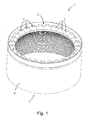
- An optical system 1 according to the invention Fig. 1 to 3 has a cylindrical basic shape, wherein a first end face 2 and one of the first end face 2 opposite end face 7 are connected via a shell side 8.
- the shell side 8 defines a light exit surface 8 of the optics 1.
- the light exit surface 8 is formed coaxially to a central axis 9 of the optics 1, which can be designed in particular as the symmetry axis of the optics 1.
- the optic 1 is produced as a refractive or light-conducting optic 1, for example, made of a transparent plastic material, in particular of PMMA, PC or PMMI.
- a plurality of light coupling elements 3 is provided in the region of the first end face 2.
- the Lichteinkoppel institute 3 are individually formed, raised and drop-shaped.
- a trough-shaped recess 4 is provided at each Lichteinkoppelelement 3 .
- the trough-shaped recess 4 has an optically effective, first boundary surface 5, which serves as a light input surface 5 of the light coupling element 3.
- the light coupling surface 5 has a plurality of partial surfaces 5.1, 5.2, 5.3.
- the partial surfaces 5.1, 5.2, 5.3 are in any case sectionally continuously curved and convex.
- the drop shape of the light coupling elements 3 results from the shell side, optically effective second boundary surface. 6
- the light coupling elements 3 have an optical axis 10, which extends parallel to the shell side 8 and the central axis 9.
- the light coupling elements 3 have perpendicular to the optical axis 10 in any case an approximately elliptical cross section.
- the second boundary surfaces 6 are formed convexly curved.
- the Lichteinkoppel implant 3 are evenly spaced circumferentially distributed and adjacent to the shell side 8 is provided.
- a recess 11 is formed in the region of the second end face 7, a recess 11 is formed.
- a boundary surface 12 of the recess 11 defines a light output surface 12 having a plurality of light output elements 13.
- the light output elements 13 are presently designed in the manner of an annularly extended prism structure.
- the prism structure defines a step contour, in which optically effective partial surfaces 13.1 and optically non-effective partial surfaces 13.2 alternate.
- the optically effective partial surfaces 13.1 and the optically inactive partial surfaces 13.2 are annularly formed, wherein the optically inactive partial surfaces 13.2 are oriented substantially parallel to the central axis 9 and wherein between the central axis 9 and the optically effective partial surfaces 13.1 a flank angle 14 of the prism structure is formed.
- a circumferential groove 15 provided on a shell side 8 separates a first region 16 of the optical system 1 which has the light coupling elements 3 from a second one Area 17, which has the recess 11 with the light output surface 12.
- a shell-side circumferential, annular web 25 is formed coaxially to the central axis 9, which comprises the light coupling elements 3 from the outside.
- the Fig. 4 to 9 show the photometric details of the optics 1 and selected beam paths for different light coupling elements 3.
- a designed as a light emitting diode light source 22 is coupled via the light input surface 5 in the optical system 1.
- a central first partial surface 5.1 of the light coupling surface 5 is shaped such that the light coupled in via the first partial surface 5.1 is bundled and directed in the direction of the light coupling-out surface 12.
- About the lateral faces 5.2, 5.3 in the optics 1 coupled light is focused and hits the shell-side second boundary surface 6 of the Lichteinkoppelementide 3.
- the second boundary surface 6 of the light coupling elements 3 is designed in the manner of a total reflection surface such that at least a majority of the over Part surface 5.2, 5.3 coupled light is deflected when hitting the boundary surface 6 in the direction of the light exit surface 12.
- the Lichteinkoppel elite 3 of the optics 1 are designed differently. They differ in particular with regard to the shape of the first optically effective boundary surface 5 and the shell-side second optically effective boundary surface 6.
- a first type of light coupling element 3 Fig. 5 is designed as a narrow-emitting Lichteinkoppel innovation 3.1 so that the coupled via the Lichteinkoppel components 5 light in a narrow first Abstrahlkegel 18 with an opening angle 19 of 40 ° +/- 5 ° relative to the optical axis 10 in the direction of the light output surface 12 is radiated. The thus emitted light hits completely on the light outcoupling surface 12 a wide-radiating Lichteinkoppelelement 3.2 after Fig.
- the light output surface 12 is provided with respect to the optical axis 10 of the light coupling elements 3 in front of the Lichteinkoppel instituten 3, that a predominant part of the injected light directly or after total reflection at the second boundary surface 6 of the light coupling elements 3 on the light output surface 12 and that only a small part of the coupled-in light strikes the light-emitting surface 8 directly or after the total reflection at the boundary surface 6 of the light-coupling elements 3, without being deflected beforehand at the light-outcoupling surface 12.
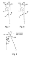
- the Fig. 7 to 9 show that the flank angle 14 of the light output elements 13 is connected in a variable position.
- the prism structure In the region of the narrow emission light coupling element 3.1, the prism structure is made less steep than in the region of a broadly emitting light coupling element 3.2.
- a transition between the steeper inclined flank angle 14 and the less steep flank angle 14 is designed continuously and continuously.
- asymmetrically radiating Lichteinkoppeliana 3.3 are provided.
- the asymmetrically emitting light coupling elements 3.3 are designed such that a radiation angle in a first half-sphere is greater than a radiation angle in a second half-sphere. In this respect, an asymmetrical emission characteristic results for the medium-width light coupling elements 3.3.
- the present optics 1 is provided with twenty eight evenly distributed on the circumference arranged Lichteinkoppel comprisen 3.
- the Lichteinkoppel elite 3 are provided at an angle of approximately 12.86 ° to each other.
- Seen in the circumferential direction are a first light coupling element 3, a sixth light coupling element 3, a seventh light coupling element 3, an eighth light coupling element 3, a ninth light coupling element 3, a tenth light coupling element 3, a fifteenth light coupling element 3, a twentieth light coupling element 3, a twenty-first light coupling element 3
- Twenty-second light coupling element 3 a twenty-third light coupling element 3 and a twenty-fourth light coupling element 3 in the manner of the broad-emitting light coupling element 3.2 trained.
- a second light input element 3, a fourteenth light input element 3, a sixteenth light input element 3 and a twenty-eighth light input element 3 are formed in the manner of the third light coupling element 3.3 and provide an asymmetric light distribution. The provided at three o'clock light input element 3 is counted here as the first light input element 3. The further count is clockwise.
- An illumination device comprises the optics 1 and a plurality of light-emitting diodes 22 as light sources.
- Each individual light sources 22 is associated with a light coupling element 3.
- the number of light sources 22 is less than the number of light coupling elements 3 of the optical system 1.
- a first configuration of the lighting device according to Fig. 10 It is provided that a total of fourteen light sources 22 are provided, wherein, starting with the first light coupling element 3, each second light coupling element 3 regularly provides a light source 22. This results in a configuration in which a symmetrical assembly with respect to a first transverse central axis 23 and a second transverse central axis 24, which is provided perpendicular to the first transverse central axis 23, is realized.
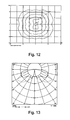
- Fig. 12 shows the symmetrical light distribution as an example of a lighting device with a net light flux of 2000 Im, wherein the lighting device is mounted at a height of about 4 m.
- a Corresponding luminous intensity distribution curve in polar coordinate representation for the symmetrical light distribution is in Fig. 13 played.
- the lighting device with symmetrical assembly is used, for example, for decorative lamps which are provided in parking lots or in parks and serve to illuminate a substantially rectangular illumination surface as homogeneously as possible.
- a substantially rectangular illumination surface as homogeneously as possible.
- illumination of the corners is ensured by the special distribution of the narrowly radiating light coupling elements 3.1 and the broadly radiating light coupling elements 3.2.
- the assignment of the light sources 22 to the optics 1 is asymmetric.
- fourteen light sources 22 are provided, wherein a first light input element 3.2, a second light input element 3.3, a fourteenth Lichteinkoppelelement 3.3, the fifteenth Lichteinkoppelelement 3.3, the sixteenth Lichteinkoppelelement 3.1, the seventeenth Lichteinkoppelelement 3.1, the eighteenth Lichteinkoppelelement 3.1, the nineteenth Lichteinkoppelelement 3.1, the Twenty-first Lichteinkoppelelement 3.2, the twenty-third Lichteinkoppelelement 3.2, the twenty-fifth Lichteinkoppelelement 3.1, the twenty-sixth Lichteinkoppelelement 3.1, the twenty-seventh Lichteinkoppelelement 3.1 and the twenty-eighth Lichteinkoppelelement 3.3 each having a light sources 22 is assigned.
- the schematic representation of the light distribution for the asymmetric lighting device according to Fig. 15 shows that the light is mainly emitted in a first half-plane.
- Fig. 16 an asymmetrical light distribution.
- the asymmetry can also be found in the corresponding luminous intensity distribution curve Fig. 17 , wherein the assignment of the light sources 22 to the light coupling elements 3 takes place so that the half-plane is substantially homogeneously illuminated.
- Asymmetrically populated lighting devices are provided for example for street lights, the street lamp is assigned to the street side and the light is to be emitted in particular in the direction of the road.
Landscapes
- Engineering & Computer Science (AREA)
- General Engineering & Computer Science (AREA)
- Physics & Mathematics (AREA)
- Microelectronics & Electronic Packaging (AREA)
- Optics & Photonics (AREA)
- Non-Portable Lighting Devices Or Systems Thereof (AREA)
Abstract
Description
- Die Erfindung betrifft eine Optik und eine Beleuchtungsvorrichtung, wie sie beispielsweise bei Dekorleuchten eingesetzt werden. Insbesondere betrifft die Erfindung eine Optik und eine Beleuchtungsvorrichtung für Pilzleuchten, die vorgesehen werden, um Plätze, Promenaden oder Straßen auszuleuchten.
- Bekannt sind refraktive Optiken und Beleuchtungsvorrichtungen mit derartigen Optiken, bei denen das Licht von einer Mehrzahl von Lichtquellen über eine Stirnseite in einen im Wesentlichen ringförmigen Körper eingekoppelt wird. Zur Einkopplung sind an der Stirnseite Lichteinkoppelelemente vorgesehen. Die Lichteinkoppelelemente bündeln das von den Lichtquellen abgestrahlte Licht so, dass es im Wesentlichen parallel auf eine als Lichtauskoppelfläche ausgebildete Umlenkfläche trifft. Die Umlenkfläche, welche durch einen Bezug zu einer Längsmittelachse des Optikkörpers als kegelstumpfartig angestellte Innenmantelfläche ausgebildet ist, lenkt das Licht dann in Richtung einer zylindrischen Außenmantelfläche des Optikkörpers. Die Außenmantelfläche des Optikkörpers definiert eine Lichtaustrittsfläche. Die Umlenkung des Lichts an der Lichtauskoppelfläche erfolgt um einen Winkel von 90°, wobei das Licht im Wesentlichen parallel zur Mantelfläche auf die Auskoppelelemente trifft und dann unter einem Winkel von 90° zur Längsmittelachse abgestrahlt wird. Derartige Optiken finden beispielsweise bei Signalleuchten Verwendung.
- Aufgabe der vorliegenden Erfindung ist es, eine refraktive Optik für eine Beleuchtungsvorrichtung sowie die Beleuchtungsvorrichtung anzugeben, welche zu Beleuchtungszwecken verwendet werden kann. Insbesondere soll eine vorgegebene Fläche möglichst homogen ausgeleuchtet werden. Um eine Anpassung der Beleuchtungssituation an das jeweilige Anwendungsszenario zu gewährleisten, sollen darüber hinaus mit einer einzigen Optik eine erste homogene Lichtverteilung und eine zweite Lichtverteilung bereitgestellt werden.
- Zur Lösung der Aufgabe weist die erfindungsgemäße Optik die Merkmale der unabhängigen Patentansprüche 1 und 3 auf.
- Der besondere Vorteil der Erfindung besteht darin, dass durch das Formen eines Abstrahlkegels eine hohe Homogenität in der Lichtverteilung bereitgestellt wird. Insbesondere gelingt es, mit einer begrenzten Anzahl von am Umfang beispielsweise regelmäßig verteilten beziehungsweise beabstandeten Lichtquellen eine die Homogenität der Lichtverteilung fördernde Durchmischung der gebündelten Strahlen zu bewirken. Der Lichtstrom der Lichtquellen wird somit in der Optik verteilt und die zu beleuchtende Fläche kann im Wesentlichen homogen ausgeleuchtet werden.
- Insbesondere kann vorgesehen sein, dass die Lichteinkoppelelemente an der ersten Stirnseite ringförmig am Umfang verteilt und benachbart zu der als Lichtaustrittsfläche dienenden Mantelseite vorgesehen sind. Beispielsweise können an den Lichteinkoppelelementen muldenförmige Ausnehmungen vorgesehen sein, wobei die muldenförmige Ausnehmung eine als eine Lichteinkoppelfläche dienende, optisch wirksame erste Begrenzungsfläche definiert. Die Lichtquellen können nach Art von Leuchtdioden ausgebildet sein und jedenfalls abschnittsweise im Bereich der muldenförmigen Ausnehmung vorgesehen sein. Die erste Begrenzungsfläche kann eine Mehrzahl von Teilfläche aufweisen, wobei die Lichteinkoppelfläche beziehungsweise jede einzelne Teilfläche jedenfalls abschnittsweise stetig gekrümmt ausgebildet sein kann. Insbesondere kann die Lichteinkoppelfläche jedenfalls abschnittsweise konvex gekrümmt sein. Beispielsweise können die Lichteinkoppelelemente separat ausgeformt und insbesondere tropfenförmig gebildet sein. Die Lichteinkoppelelemente können insofern senkrecht zu der optischen Achse einen jedenfalls näherungsweise elliptischen Querschnitt aufweisen.
- Eine mantelseitige Begrenzungsfläche der Optikelemente kann hierbei als eine zweite optisch wirksame Begrenzungsfläche ausgebildet sein. Insbesondere kann die zweite optische Begrenzungsfläche nach Art einer Totalreflexionsfläche ausgebildet sein derart, dass wenigstens ein Teil des über die Lichteinkoppelfläche eingekoppelten Lichts beim Auftreffen auf die zweite Begrenzungsfläche totalreflektiert wird. Bevorzugt wird das auf die zweite Begrenzungsfläche treffende Licht in Richtung der Lichtauskoppelfläche totalreflektiert.
- Die an der Lichtauskoppelfläche vorgesehenen Lichtauskoppelelemente können beispielsweise nach Art einer umlaufenden beziehungsweise ringförmigen Prismenstruktur realisiert sein. Ein Flankenwinkel der Prismenstruktur kann bezogen auf die Längsmittelachse der Optik derart bestimmt sein, dass über die Lichteinkoppelelemente eingekoppeltes Licht beim Auftreffen auf die Prismenstruktur in Richtung der Lichtaustrittsfläche totalreflektiert wird.
- Die Lichteinkoppelelemente können relativ zur Lichtauskoppelfläche beziehungsweise den hieran vorgesehenen Lichtauskoppelelementen derart vorgesehen sein, dass in die Optik eingekoppeltes Licht jedenfalls zu einem überwiegenden Teil unmittelbar beziehungsweise nach der Totalreflexion an der zweiten Begrenzungsfläche der Lichteinkoppelelemente auf die Lichtauskoppelfläche trifft, und dass nur ein geringer Teil des eingekoppelten Lichts unmittelbar beziehungsweise nach der Totalreflexion an der zweiten Begrenzungsfläche auf die Lichtaustrittsfläche trifft, ohne an der Lichtauskoppelfläche umgelenkt worden zu sein.
- Nach einer bevorzugten Ausführungsform der Erfindung werden wenigstens zwei hinsichtlich ihrer Formgebung unterschiedliche Lichteinkoppelelemente vorgesehen. Insbesondere unterscheiden sich die Lichteinkoppelelemente hinsichtlich der Gestaltung der ersten optisch wirksamen Begrenzungsfläche beziehungsweise der zweiten optisch wirksamen Begrenzungsfläche. Vorteilhaft kann durch das Vorsehen von unterschiedlichen Lichteinkoppelelementen eine große Vielzahl verschiedener Lichtverteilungen bereitgestellt werden. Beispielsweise kann eine quadratische beziehungsweise rechteckige Fläche homogen ausgeleuchtet werden. Hierbei wird besonders viel Licht in Richtung der Ecken der Beleuchtungsfläche gelenkt.
- Nach einer Weiterbildung der Erfindung ist mindestens ein eng abstrahlendes Lichteinkoppelelement vorgesehen, welches einen engen Abstrahlkegel mit einem Öffnungswinkel von 40° +/- 5° bildet. Weiter ist mindestens ein breit abstrahlendes Lichteinkoppelelement mit einem breiten Abstrahlkegel und einem Öffnungswinkel von 70° +/- 5° bezogen auf die optische Achse des Lichteinkoppelelements vorgesehen. Vorteilhaft kann über ein eng abstrahlendes Lichteinkoppelelement in die Optik eingekoppeltes Licht die Ecken einer quadratischen beziehungsweise rechteckigen Beleuchtungsfläche ausleuchten, während die breit abstrahlenden Lichteinkoppelelemente das Licht weniger weit, aber dafür breit umlenken.
- Nach einer Weiterbildung der Erfindung ist die Ausnehmung jedenfalls abschnittsweise schalenförmig ausgebildet. Insbesondere ist die als Lichtauskoppelfläche wirkende Begrenzungsfläche der Ausnehmung gebogen geformt. Vorteilhaft verbessert sich die Homogenität der Ausleuchtung durch das Vorsehen der gebogenen Lichtaustrittsfläche. Es wird insofern eine Lichtverteilung hoher Güte bereitgestellt, wobei das Licht so umgelenkt wird, dass es in einer Montageposition der Optik seitlich und nach unten abgestrahlt wird.
- Nach einer Weiterbildung der Erfindung ist vorgesehen, dass der Flankenwinkel der Prismenstruktur ortsvariabel gestaltet ist. Insbesondere kann vorgesehen sein, dass die Prismenstruktur vor den eng abstrahlenden Lichteinkoppelelementen weniger steil angestellt ist als die gleiche Prismenstruktur vor den breit abstrahlenden Lichteinkoppelelementen. Vor den breit abstrahlenden Lichteinkoppelelementen ist insofern der zwischen der Prismenstruktur und der Mittelachse gebildete Flankenwinkel spitzer ausgebildet beziehungsweise kleiner als vor den eng abstrahlenden Lichteinkoppelelementen. Der Übergang von dem steilen Flankenwinkel zu dem weniger steilen Flankenwinkel kann dabei insbesondere kontinuierlich erfolgen. Vorteilhaft kann durch das Vorsehen unterschiedlicher Flankenwinkel eine Abstrahlweite der Optik variiert werden. Es ist insofern so, dass über die Lichtauskoppelelemente mit dem ortsvariablen Flankenwinkel die Lichtverteilung beeinflusst werden kann. Die kontinuierliche Veränderung des Flankenwinkels begünstigt zum einen eine homogene Ausleuchtung und vermeidet zum anderen Stufen beziehungsweise Sprünge, welche als helle beziehungsweise dunkle Bereiche in der Lichtverteilung wahrgenommen werden können.
- Zur Lösung der Aufgabe umfasst die Beleuchtungsvorrichtung eine Optik nach einem der Ansprüche 1 bis 9 sowie eine Mehrzahl von Leuchtdioden als Lichtquellen, wobei jeder Leuchtdiode ein Lichteinkoppelelement zugeordnet ist und wobei eine Anzahl der Leuchtdioden geringer ist als eine Anzahl der Lichteinkoppelelemente der Optik. Beispielsweise können achtundzwanzig Lichteinkoppelelemente und vierzehn Leuchtdioden vorgesehen werden, wobei in einer ersten Betriebskonfiguration der Beleuchtungsvorrichtung an jedem zweiten Lichteinkoppelelement eine Leuchtdiode vorgesehen ist und wobei in einer zweiten Betriebskonfiguration die Lichtquellen ungleichförmig an den Lichteinkoppelelementen vorgesehen sind.
- Der besondere Vorteil der Erfindung besteht darin, dass durch das Vorsehen einer Vielzahl von Lichteinkoppelelementen eine variable Bestückung derselben mit Lichtquellen möglich ist. Durch das variable Bestücken der Optik mit Lichtquellen können bei Verwendung der gleichen Optik unterschiedliche Lichtverteilungen bereitgestellt werden. Beispielsweise kann in der ersten Betriebskonfiguration eine symmetrische Lichtverteilung bereitgestellt werden, welche vorteilhaft Verwendung findet bei Dekorleuchten, die vorgesehen sind, um einen Parkplatz flächig auszuleuchten. Demgegenüber kann durch das ungleichförmige Anordnen der Lichtquellen eine asymmetrische Lichtverteilung, insbesondere eine einseitige Lichtverteilung bereitgestellt werden. Diese Lichtverteilung ist vorteilhaft bei der Verwendung der Beleuchtungsvorrichtung zur Ausleuchtung von Straßenzügen, Promenaden oder dergleichen. Insgesamt reduziert sich so der Design- und Montageaufwand, da Dekorleuchten für unterschiedliche Anwendungen mit dem gleichen Optikkörper ausgestattet werden können und der Optikkörper demzufolge in großer Stückzahl gefertigt wird. Veränderlich ist allein die Anordnung der Lichtquellen. Beispielsweise kann für beide Betriebskonfigurationen ein gleicher Schaltungsträger verwendet werden, welcher jedoch in unterschiedlicher Weise mit Lichtquellen bestückt wird.
- Den weiteren Unteransprüchen und der nachfolgenden Beschreibung sind weitere Vorteile, Merkmale und Einzelheiten der Erfindung zu entnehmen. Dort erwähnte Merkmale können jeweils einzeln für sich oder auch in beliebiger Kombination erfindungswesentlich sein. Erfindungsgemäß beschriebene Merkmale und Details der Optik gelten selbstverständlich auch im Zusammenhang mit der erfindungsgemäßen Beleuchtungsvorrichtung und umgekehrt. So kann auf die Offenbarung zu den einzelnen Erfindungsaspekten stets wechselseitig Bezug genommen werden. Die Zeichnungen dienen lediglich beispielhaft der Klarstellung der Erfindung und haben keinen einschränkenden Charakter.
- Anhand der beigefügten Zeichnungen wird die Erfindung nachfolgend näher erläutert. Dabei zeigt:
- Fig. 1
- eine perspektivische Ansicht einer erfindungsgemäßen Optik,
- Fig. 2
- eine Aufsicht auf die Optik nach
Fig. 1 , - Fig. 3
- eine Schnittdarstellung der Optik nach dem Schnitt A-A gemäß
Fig. 2 , - Fig. 4
- einen Teilschnitt der Optik nach
Fig. 3 mit Darstellung des Strahlengangs, - Fig. 5
- eine Schnittdarstellung nach dem Schnitt B-B gemäß
Fig. 2 mit dargestelltem Strahlengang, - Fig. 6
- eine Schnittdarstellung nach dem Schnitt C-C gemäß
Fig. 2 mit Darstellung des Strahlengangs, - Fig. 7
- eine Schnittdarstellung nach dem Schnitt D-D nach
Fig. 2 , - Fig. 8
- eine Schnittdarstellung nach dem Schnitt E-E nach
Fig. 2 , - Fig. 9
- eine Gegenüberstellung der Details X und Y nach den
Fig. 7 und 8 , - Fig. 10
- eine erste Betriebskonfiguration einer erfindungsgemäßen Beleuchtungsvorrichtung mit einer regelmäßigen Anordnung einer Mehrzahl von Lichtquellen,
- Fig. 11
- eine Prinzipdarstellung der Abstrahlcharakteristik der Beleuchtungsvorrichtung in der ersten Betriebskonfiguration nach
Fig. 10 , - Fig. 12
- eine Lichtverteilung der Beleuchtungsvorrichtung in der ersten Betriebskonfiguration nach
Fig. 10 , - Fig. 13
- eine Lichtstärkeverteilungskurve der Beleuchtungsvorrichtung nach
Fig. 10 in einer Polar-Koordinatendarstellung, - Fig. 14
- eine zweite Betriebskonfiguration einer erfindungsgemäßen Beleuchtungsvorrichtung mit einer regelmäßigen Anordnung der Mehrzahl von Lichtquellen,
- Fig. 15
- eine Prinzipdarstellung der Abstrahlcharakteristik der Beleuchtungsvorrichtung in der zweiten Betriebskonfiguration nach
Fig. 14 , - Fig. 16
- eine Lichtverteilung der Beleuchtungsvorrichtung in der zweiten Betriebskonfiguration nach
Fig. 14 und - Fig. 17
- eine Lichtstärkeverteilungskurve der Beleuchtungsvorrichtung nach
Fig. 14 in einer Polar-Koordinatendarstellung. - Eine erfindungsgemäße Optik 1 nach den
Fig. 1 bis 3 weist eine zylinderförmige Grundform auf, wobei eine erste Stirnseite 2 und eine der ersten Stirnseite 2 gegenüberliegenden Stirnseite 7 über eine Mantelseite 8 verbunden sind. Die Mantelseite 8 definiert eine Lichtaustrittsfläche 8 der Optik 1. Die Lichtaustrittsfläche 8 ist koaxial zu einer Mittelachse 9 der Optik 1 ausgebildet, welche insbesondere als Symmetrieachse der Optik 1 ausgeführt sein kann. Die Optik 1 ist als refraktive beziehungsweise lichtleitende Optik 1 beispielsweise aus einem transparenten Kunststoffmaterial, insbesondere aus PMMA, PC oder PMMI hergestellt. - Im Bereich der ersten Stirnseite 2 ist eine Mehrzahl von Lichteinkoppelelementen 3 vorgesehen. Die Lichteinkoppelelemente 3 sind einzeln ausgeformt, erhaben und tropfenförmig. An jedem Lichteinkoppelelement 3 ist eine muldenförmige Ausnehmung 4 vorgesehen. Die muldenförmige Ausnehmung 4 weist eine optisch wirksame, erste Begrenzungsfläche 5 auf, welche als eine Lichteinkoppelfläche 5 des Lichteinkoppelelements 3 dient. Die Lichteinkoppelfläche 5 weist eine Mehrzahl von Teilflächen 5.1, 5.2, 5.3 auf. Die Teilflächen 5.1, 5.2, 5.3 sind jedenfalls abschnittsweise stetig gekrümmt und konvex geformt. Die Tropfenform der Lichteinkoppelelemente 3 ergibt sich durch die mantelseitige, optisch wirksam zweite Begrenzungsfläche 6.
- Die Lichteinkoppelelemente 3 besitzen eine optische Achse 10, welche sich parallel zur Mantelseite 8 beziehungsweise zur Mittelachse 9 erstreckt. Die Lichteinkoppelelemente 3 besitzen senkrecht zu der optischen Achse 10 einen jedenfalls näherungsweise elliptischen Querschnitt. Die zweiten Begrenzungsflächen 6 sind konvex gekrümmt ausgebildet. Die Lichteinkoppelelemente 3 sind gleichmäßig beabstandet umfangmäßig verteilt und benachbart zu der Mantelseite 8 vorgesehen.
- Im Bereich der zweiten Stirnseite 7 ist eine Ausnehmung 11 gebildet. Eine Begrenzungsfläche 12 der Ausnehmung 11 definiert eine Lichtauskoppelfläche 12 mit einer Mehrzahl von Lichtauskoppelelementen 13. Die Lichtauskoppelelemente 13 sind vorliegend nach Art einer ringförmig erstreckten Prismenstruktur ausgebildet. Die Prismenstruktur definiert eine Stufenkontur, bei der sich optisch wirksame Teilflächen 13.1 und optisch nicht wirksame Teilflächen 13.2 abwechseln. Jeweils sind die optisch wirksamen Teilflächen 13.1 und die optisch nicht wirksamen Teilflächen 13.2 ringförmig gebildet, wobei die optisch nicht wirksamen Teilflächen 13.2 im Wesentlichen parallel zu der Mittelachse 9 orientiert sind und wobei zwischen der Mittelachse 9 und den optisch wirksamen Teilflächen 13.1 ein Flankenwinkel 14 der Prismenstruktur gebildet ist.
- Eine an einer Mantelseite 8 vorgesehene umlaufende Nut 15 trennt einen die Lichteinkoppelelemente 3 aufweisenden ersten Bereich 16 der Optik 1 von einem zweiten Bereich 17, der die Ausnehmung 11 mit der Lichtauskoppelfläche 12 aufweist. Im ersten Bereich 16 ist koaxial zu der Mittelachse 9 ein mantelseitig umlaufender, ringförmiger Steg 25 gebildet, welche die Lichteinkoppelelemente 3 von außen umfasst.
- Die
Fig. 4 bis 9 zeigen die lichttechnischen Details der Optik 1 sowie ausgewählte Strahlenverläufe für verschiedene Lichteinkoppelelemente 3. Von einer als Leuchtdiode ausgebildeten Lichtquelle 22 abgestrahltes Licht wird über die Lichteinkoppelfläche 5 in die Optik 1 eingekoppelt. Eine zentrale erste Teilfläche 5.1 der Lichteinkoppelfläche 5 ist so geformt, dass das über die erste Teilfläche 5.1 eingekoppelte Licht gebündelt in Richtung der Lichtauskoppelfläche 12 gelenkt wird. Über die seitlichen Teilflächen 5.2, 5.3 in die Optik 1 eingekoppeltes Licht wird gebündelt und trifft auf die mantelseitige zweite Begrenzungsfläche 6 der Lichteinkoppelelemente 3. Die zweite Begrenzungsfläche 6 der Lichteinkoppelelemente 3 ist nach Art einer Totalreflexionsfläche derart ausgebildet, dass jedenfalls ein überwiegende Teil des über die Teilfläche 5.2, 5.3 eingekoppelten Lichts beim Auftreffen auf die Begrenzungsfläche 6 in Richtung der Lichtaustrittsfläche 12 umgelenkt wird. - Die Lichteinkoppelelemente 3 der Optik 1 sind unterschiedlich ausgebildet. Sie unterscheiden sich insbesondere hinsichtlich der Form der ersten optisch wirksamen Begrenzungsfläche 5 sowie der mantelseitigen zweiten optisch wirksamen Begrenzungsfläche 6. Eine erste Art von Lichteinkoppelelementen 3.1 nach
Fig. 5 ist als eng abstrahlende Lichteinkoppelelemente 3.1 so ausgebildet, dass das über die Lichteinkoppelfläche 5 eingekoppelte Licht in einem engen ersten Abstrahlkegel 18 mit einem Öffnungswinkel 19 von 40° +/- 5° bezogen auf die optische Achse 10 in Richtung der Lichtauskoppelfläche 12 abgestrahlt wird. Das so abgestrahlte Licht trifft vollständig auf die Lichtauskoppelfläche 12. Ein breit abstrahlendes Lichteinkoppelelement 3.2 nachFig. 6 weist einen breiten zweiten Abstrahlkegel 20 mit einem zweiten Öffnungswinkel 21 von 70° +/- 5° bezogen auf die optische Achse 10 auf. Hierbei ist die Lichtauskoppelfläche 12 bezogen auf die optische Achse 10 der Lichteinkoppelelemente 3 derart vor den Lichteinkoppelelementen 3 vorgesehen, dass ein überwiegender Teil des eingekoppelten Lichts unmittelbar beziehungsweise nach der Totalreflexion an der zweiten Begrenzungsfläche 6 der Lichteinkoppelelemente 3 auf die Lichtauskoppelfläche 12 trifft und dass nur ein geringer Teil des eingekoppelten Lichts unmittelbar beziehungsweise nach der Totalreflexion an der Begrenzungsfläche 6 der Lichteinkoppelelemente 3 auf die Lichtaustrittsfläche 8 trifft, ohne zuvor an der Lichtauskoppelfläche 12 umgelenkt zu werden. - Die
Fig. 7 bis 9 zeigen, dass der Flankenwinkel 14 der Lichtauskoppelelemente 13 ortsvariabel geschaltet ist. Im Bereich des eng abstrahlenden Lichteinkoppelelements 3.1 ist die Prismenstruktur weniger steil angestellt als im Bereich eines breit abstrahlenden Lichteinkoppelelements 3.2. Der Flankenwinkel 14, welcher zwischen der optisch wirksamen Teilfläche 13.1 der Prismenstruktur und der Mittelachse 9 gebildet ist, ist insofern vor den breit abstrahlenden Lichteinkoppelelementen 3.2 spitzer beziehungsweise kleiner als vor den eng abstrahlenden Lichteinkoppelelementen 3.1. Ein Übergang zwischen dem steiler angestellten Flankenwinkel 14 und dem weniger steil angestellten Flankenwinkel 14 ist dabei kontinuierlich und stufenlos gestaltet. - Neben den eng abstrahlenden Lichteinkoppelelementen 3.1 und den breit abstrahlenden Lichteinkoppelelementen 3.2 sind asymmetrisch abstrahlende Lichteinkoppelelemente 3.3 vorgesehen. Die asymmetrisch abstrahlenden Lichteinkoppelelemente 3.3 sind derart ausgeführt, dass ein Abstrahlwinkel in eine erste Halbsphäre größer ist als ein Abstrahlwinkel in eine zweite Halbsphäre. Insofern ergibt sich eine asymmetrische Abstrahlcharakteristik für die mittelbreiten Lichteinkoppelelemente 3.3.
- Konkret ist die vorliegende Optik 1 mit achtundzwanzig am Umfang gleichmäßig verteilt angeordneten Lichteinkoppelelementen 3 vorgesehen. Die Lichteinkoppelelemente 3 sind unter einem Winkel von näherungsweise 12,86° zueinander vorgesehen. In Umfangsrichtung gesehen sind ein erstes Lichteinkoppelelement 3, ein sechstes Lichteinkoppelelement 3, ein siebtes Lichteinkoppelelement 3, ein achtes Lichteinkoppelelement 3, ein neuntes Lichteinkoppelelement 3, ein zehntes Lichteinkoppelelement 3, ein fünfzehntes Lichteinkoppelelement 3, ein zwanzigstes Lichteinkoppelelement 3, ein einundzwanzigstes Lichteinkoppelelement 3, ein zweiundzwanzigstes Lichteinkoppelelement 3, ein dreiundzwanzigstes Lichteinkoppelelement 3 und ein vierundzwanzigstes Lichteinkoppelelement 3 nach Art des breit abstrahlenden Lichteinkoppelelements 3.2 ausgebildet. Ein drittes Lichteinkoppelelement 3, ein viertes Lichteinkoppelelement 3, ein fünftes Lichteinkoppelelement 3, ein elftes Lichteinkoppelelement 3, ein zwölftes Lichteinkoppelelement 3, ein dreizehntes Lichteinkoppelelement 3, ein siebzehntes Lichteinkoppelelement 3, ein achtzehntes Lichteinkoppelelement 3, ein neunzehntes Lichteinkoppelelement 3, ein fünfundzwanzigstes Lichteinkoppelelement 3, ein sechsundzwanzigstes Lichteinkoppelelement 3 und ein siebenundzwanzigstes Lichteinkoppelelement 3 sind nach Art des eng abstrahlenden Lichteinkoppelelements 3.1 ausgebildet sind. Ein zweites Lichteinkoppelelement 3, ein vierzehntes Lichteinkoppelelement 3, ein sechzehntes Lichteinkoppelelement 3 und ein achtundzwanzigstes Lichteinkoppelelement 3 sind nach Art des dritten Lichteinkoppelelements 3.3 ausgebildet und stellen eine asymmetrische Lichtverteilung bereit. Das auf drei Uhr vorgesehene Lichteinkoppelelement 3 ist hierbei als erstes Lichteinkoppelelement 3 gezählt. Die weitere Zählung erfolgt im Uhrzeigersinn.
- Eine erfindungsgemäße Beleuchtungsvorrichtung umfasst die Optik 1 sowie eine Mehrzahl von Leuchtdioden 22 als Lichtquellen. Jeder einzelnen Lichtquellen 22 ist ein Lichteinkoppelelement 3 zugeordnet. Insgesamt ist die Anzahl der Lichtquellen 22 geringer als die Anzahl der Lichteinkoppelelemente 3 der Optik 1. Nach einer ersten Konfiguration der Beleuchtungsvorrichtung gemäß
Fig. 10 ist vorgesehen, dass insgesamt vierzehn Lichtquellen 22 vorgesehen werden, wobei beginnend mit dem ersten Lichteinkoppelelement 3 regelmäßig jedes zweite Lichteinkoppelelement 3 eine Lichtquellen 22 vorsieht. Es ergibt sich hierdurch eine Konfiguration, in der eine symmetrische Bestückung in Bezug auf eine erste Quermittelachse 23 und eine zweite Quermittelachse 24, welche senkrecht zur ersten Quermittelachse 23 vorgesehen ist, realisiert ist. Infolge der symmetrischen Bestückung und der Zuordnung der Lichtquellen 22 zu den verschiedenen eng abstrahlenden Lichteinkoppelelementen 3.1 beziehungsweise den verschiedenen breit abstrahlenden Lichteinkoppelelementen 3.2 ergibt sich eine symmetrische, im Wesentlichen rechteckige Lichtverteilung, welche dem Prinzip nach inFig. 11 dargestellt ist.Fig. 12 zeigt die symmetrische Lichtverteilung exemplarisch für eine Beleuchtungsvorrichtung mit einem Nettolichtstrom von 2000 Im, wobei die Beleuchtungsvorrichtung in einer Höhe von zirka 4 m montiert ist. Eine korrespondierende Lichtstärkeverteilungskurve in Polar-Koordinatendarstellung für die symmetrische Lichtverteilung ist inFig. 13 wiedergegeben. - Die Beleuchtungsvorrichtung mit symmetrischer Bestückung wird beispielsweise verwendet für Dekorleuchten, welche auf Parkplätzen oder in Parks vorgesehen werden und dazu dienen, eine im Wesentlichen rechteckige Beleuchtungsfläche möglichst homogen auszuleuchten. Hierbei wird durch die spezielle Verteilung der eng abstrahlenden Lichteinkoppelelemente 3.1 und der breit abstrahlenden Lichteinkoppelelemente 3.2 neben der homogenen Ausleuchtung der Fläche insbesondere auch eine Ausleuchtung der Ecken gewährleistet.
- In einer zweiten Betriebskonfiguration nach der
Figur 14 erfolgt die Zuordnung der Lichtquellen 22 zu der Optik 1 asymmetrisch. Grundsätzlich sind neuerlich vierzehn Lichtquellen 22 vorgesehen, wobei einem ersten Lichteinkoppelelement 3.2, einem zweiten Lichteinkoppelelement 3.3, einem vierzehnten Lichteinkoppelelement 3.3, dem fünfzehnten Lichteinkoppelelement 3.3, dem sechzehnten Lichteinkoppelelement 3.1, dem siebzehnten Lichteinkoppelelement 3.1, dem achtzehnten Lichteinkoppelelement 3.1, dem neunzehnten Lichteinkoppelelement 3.1, dem einundzwanzigstens Lichteinkoppelelement 3.2, dem dreiundzwanzigsten Lichteinkoppelelement 3.2, dem fünfundzwanzigsten Lichteinkoppelelement 3.1, dem sechsundzwanzigsten Lichteinkoppelelement 3.1, dem siebenundzwanzigsten Lichteinkoppelelement 3.1 und dem achtundzwanzigsten Lichteinkoppelelement 3.3 jeweils eine Lichtquellen 22 zugeordnet ist. - Die Prinzipdarstellung der Lichtverteilung für die asymmetrische Beleuchtungsvorrichtung nach
Fig. 15 zeigt, dass das Licht vorwiegend in eine erste Halbebene abgestrahlt wird. Entsprechend zeigtFig. 16 eine asymmetrische Lichtverteilung. Die Asymmetrie findet sich auch in der korrespondierenden Lichtstärkeverteilungskurve nachFig. 17 , wobei die Zuordnung der Lichtquellen 22 zu den Lichteinkoppelelementen 3 so erfolgt, dass die Halbebene im Wesentlichen homogen ausgeleuchtet wird. Asymmetrisch bestückte Beleuchtungsvorrichtungen werden beispielsweise für Straßenleuchten vorgesehen, wobei die Straßenleuchte der Straße seitlich zugeordnet ist und das Licht insbesondere in Richtung der Straße abgestrahlt werden soll. -
- 1
- Optik
- 2
- erste Stirnseite
- 3
- Lichteinkoppelelement
- 3.1
- eng abstrahlendes Lichteinkoppelelement
- 3.2
- breit abstrahlendes Lichteinkoppelelement
- 3.3
- asymmetrisch abstrahlendes Lichteinkoppelelement
- 4
- muldenförmige Ausnehmung
- 5
- Lichteinkoppelfläche
- 5.1
- zentrale Teilfläche
- 5.2
- seitliche Teilfläche
- 5.3
- seitliche Teilfläche
- 6
- zweite Begrenzungsfläche
- 7
- zweite Stirnseite
- 8
- Lichtaustrittsfläche
- 9
- Mittelachse
- 10
- optische Achse
- 11
- Ausnehmung
- 12
- Lichtauskoppelfläche
- 13
- Lichtauskoppelelement
- 13.1
- optisch wirksame Teilfläche
- 13.2
- optisch nicht wirksame Teilfläche
- 14
- Flankenwinkel
- 15
- umlaufende Nut
- 16
- erster Bereich
- 17
- zweiter Bereich
- 18
- Abstrahlkegel
- 19
- Öffnungswinkel
- 20
- Abstrahlkegel
- 21
- Öffnungswinkel
- 22
- Lichtquelle
- 23
- Quermittelachse
- 24
- Quermittelachse
- 25
- Steg
Claims (12)
- Optik (1) für eine Beleuchtungsvorrichtung mit mehreren Lichtquellen (22) umfassend- einen ersten Bereich (16), der für jede Lichtquelle (22) ein Lichteinkoppelelement (3, 3.1, 3.2, 3.3) aufweist, welches Licht von der Lichtquelle (22) in gebündelte Stahlen zusammenfasst,- einen zweiten Bereich (17), in dem die gebündelten Strahlen auf eine als Lichtauskoppelfläche (12) dienenden Begrenzungsfläche (12) der Optik (1) treffen und durch Totalreflexion nach außen gelenkt werden,wobei die Lichteinkoppelelemente (3, 3.1, 3.2, 3.3) in einem Umfangsbereich der Optik (1) angeordnet sind.
- Optik (1) nach Anspruch 1, dadurch gekennzeichnet, dass an den Lichteinkoppelelementen (3, 3.1, 3.2, 3.3) wenigstens eine optisch wirksame Begrenzungsfläche (3, 3.1, 3.2, 3.3) vorgesehen ist und/oder dass durch die Lichteinkoppelelemente (3, 3.1, 3.2, 3.3) gebündelte Strahlen geformt werden, welche bezogen auf eine optische Achse (10) der Lichteinkoppelelemente (3, 3.1, 3.2, 3.3) einen Abstrahlkegel (18, 20) mit einem definierten Öffnungswinkel (19, 21) bilden, und/oder dass die gebündelten Strahlen in Richtung einer Lichtaustrittsfläche (8) totalreflektiert werden, wobei die Lichtaustrittsfläche (8) eine Mantelseite (8) der Optik (1) definiert.
- Optik (1) für eine Beleuchtungsvorrichtung mit mehreren Lichtquellen (22) umfassend- eine erste Stirnseite (2), an der verteilt eine Mehrzahl von Lichteinkoppelelementen (3, 3.1, 3.2, 3.3) mit wenigstens einer optisch wirksamen Begrenzungsfläche (5, 6) vorgesehen ist,- eine sich an die erste Stirnseite (2) anschließende Mantelseite (8), welche als Lichtaustrittsfläche (8) ausgebildet ist,- eine der ersten Stirnseite (2) gegenüberliegende zweite Stirnseite (7) mit einer Ausnehmung (11), wobei eine Begrenzungsfläche (12) der Ausnehmung (11) eine Lichtauskoppelfläche (12) definiert und eine Mehrzahl von Lichtauskoppelelementen (13) aufweist, welche derart ausgebildet sind, dass über die Lichteinkoppelelemente (3, 3.1, 3.2, 3.3) eingekoppeltes Licht an den Lichtauskoppelelementen (13) in Richtung der Lichtaustrittsfläche (8) umgelenkt wird,dadurch gekennzeichnet, dass die wenigstens eine optisch wirksame Begrenzungsfläche (5, 6) des Lichteinkoppelelements (3, 3.1, 3.2, 3.3) derart geformt ist, dass Licht in einem Abstrahlkegel (18, 20) mit einem Öffnungswinkel (19, 21) von 55° +/- 20° bezogen auf eine optische Achse (10) des Lichteinkoppelelements (3, 3.1, 3.2, 3.3) abgestrahlt wird.
- Optik (1) nach einem der Ansprüche 1 bis 3, dadurch gekennzeichnet, dass wenigstens zwei unterschiedliche Lichteinkoppelelemente (3, 3.1, 3.2, 3.3) vorgesehen sind, welche sich hinsichtlich einer Formgebung- einer als eine erste optisch wirksame Begrenzungsfläche (5) gebildeten Lichteinkoppelfläche (5) und/oder- einer mantelseitigen zweiten optisch wirksamen Begrenzungsfläche (6) unterscheiden.
- Optik (1) nach einem der Ansprüche 1 bis 4, dadurch gekennzeichnet, dass mindestens ein eng abstrahlendes Lichteinkoppelelement (3, 3.1) Licht in einem engen ersten Abstrahlkegel (18) mit einem ersten Öffnungswinkel (19) von 40° +/- 5° bezogen auf die optische Achse (10) des Lichteinkoppelelements (3, 3.1) abstrahlt, und/oder dass mindestens ein breit abstrahlendes Lichteinkoppelelement 3, (3.2) Licht in einem breiten zweiten Abstrahlkegel (20) mit einem zweiten Öffnungswinkel (21) von 70° +/- 5° bezogen auf die optische Achse (10) des Lichteinkoppelelements (3, 3.2) abstrahlt.
- Optik (1) nach einem der Ansprüche 1 bis 5, dadurch gekennzeichnet, dass die Ausnehmung (11) jedenfalls abschnittsweise schalenförmig ausgebildet ist und/oder dass die Lichtauskoppelfläche (12) mindestens abschnittsweise gebogen ausgebildet ist und/oder dass die Lichtauskoppelelemente (13) eine Prismenstruktur aufweisen und/oder ringförmig ausgebildet sind.
- Optik (1) nach einem der Ansprüche 1 bis 6, dadurch gekennzeichnet, dass ein zwischen der Mittelachse (9) und der Prismenstruktur gebildeter Flankenwinkel (14) der Prismenstruktur ortsvariabel gestaltet ist und/oder dass die Prismenstruktur vor den eng abstrahlenden Lichteinkoppelelementen (3, 3.1) weniger steil angestellt ist als die gleiche Prismenstruktur vor den breit abstrahlenden Lichteinkoppelelementen (3, 3.2) und/oder dass der Flankenwinkel (14) vor den eng abstrahlenden Lichteinkoppelelementen (3, 3.1) weniger spitz ausgebildet ist als der Flankenwinkel (14) der gleichen Prismenstruktur vor den breit abstrahlenden Lichteinkoppelelementen (3, 3.2).
- Optik (1) nach einem der Ansprüche 1 bis 7, dadurch gekennzeichnet, dass eine dritte Art von Lichteinkoppelelementen (3, 3.3) vorgesehen ist, welche eine asymmetrische Abstrahlcharakteristik aufweist, und/oder dass die dritte Art von Lichteinkoppelelementen (3, 3.3) derart geformt ist, dass ein Abstrahlwinkel in eine erste Halbsphäre größer ist als der Abstrahlwinkel in eine zweite Halbsphäre.
- Optik (1) nach einem der Ansprüche 1 bis 8, dadurch gekennzeichnet, dass an der ersten Stirnseite (2) am Umfang gleichmäßig verteilt insgesamt achtundzwanzig Lichteinkoppelelemente (3, 3.1, 3.2, 3.3) vorgesehen sind, welche unter einem Winkel von näherungsweise 12,86° gleichmäßig verteilt angeordnet sind, und/oder- dass in Umfangsrichtung gesehen ein erstes Lichteinkoppelelement (3, 3.1), ein sechstes Lichteinkoppelelement (3, 3.1), ein siebtes Lichteinkoppelelement (3, 3.1), ein achtes Lichteinkoppelelement (3, 3.1), ein neuntes Lichteinkoppelelement (3, 3.1), ein zehntes Lichteinkoppelelement (3, 3.1), ein fünfzehntes Lichteinkoppelelement (3, 3.1), ein zwanzigstes Lichteinkoppelelement (3, 3.1), ein einundzwanzigstes Lichteinkoppelelement (3, 3.1), ein zweiundzwanzigstes Lichteinkoppelelement (3, 3.1), ein dreiundzwanzigstes Lichteinkoppelelement (3, 3.1) und ein vierundzwanzigstes Lichteinkoppelelement (3, 3.1) nach Art des breit abstrahlendes Lichteinkoppelelements (3, 3.1) ausgebildet sind und/oder- dass ein drittes Lichteinkoppelelement (3, 3.2), ein viertes Lichteinkoppelelement (3, 3.2), ein fünftes Lichteinkoppelelement (3, 3.2), ein elftes Lichteinkoppelelement (3, 3.2), ein zwölftes Lichteinkoppelelement (3, 3.2), ein dreizehntes Lichteinkoppelelement (3, 3.2), ein siebzehntes Lichteinkoppelelement (3, 3.2), ein achtzehntes Lichteinkoppelelement (3, 3.2), ein neunzehntes Lichteinkoppelelement (3, 3.2), ein fünfundzwanzigstes Lichteinkoppelelement (3, 3.2), ein sechsundzwanzigstes Lichteinkoppelelement (3, 3.2) und ein siebenundzwanzigstes Lichteinkoppelelement (3, 3.2) nach Art des eng abstrahlenden Lichteinkoppelelements (3, 3.2) ausgebildet sind und/oder- dass ein zweites Lichteinkoppelelement (3, 3.3), ein vierzehntes Lichteinkoppelelement (3, 3.3), ein sechzehntes Lichteinkoppelelement (3, 3.3) und ein achtundzwanzigstes Lichteinkoppelelement (3, 3.3) nach Art des dritten Lichteinkoppelelements ausgebildet sind und eine asymmetrische Lichtverteilung bereitstellen.
- Beleuchtungsvorrichtung umfassend eine Optik (1) nach einem der Ansprüche 1 bis 9 und umfassend eine Mehrzahl von Leuchtdioden (22) als Lichtquellen, wobei jeder Leuchtdiode (22) ein Lichteinkoppelelement (3, 3.1, 3.2, 3.3) zugeordnet ist und/oder wobei eine Anzahl der Leuchtdioden (22) geringer ist eine die Anzahl der Lichteinkoppelelemente (3, 3.1, 3.2, 3.3) der Optik (1).
- Beleuchtungsvorrichtung nach Anspruch 10, dadurch gekennzeichnet, dass insgesamt vierzehn Leuchtdioden (22) vorgesehen sind.
- Beleuchtungsvorrichtung nach Anspruch 10 oder 11, dadurch gekennzeichnet,- dass in einer ersten Betriebskonfiguration beginnend mit dem ersten Lichteinkoppelelement (3, 3.2) jedem zweiten Lichteinkoppelelement (3, 3.1, 3.2) eine Leuchtdiode (22) zugeordnet ist, und/oder- dass in einer zweiten Betriebskonfiguration dem ersten Lichteinkoppelelement (3, 3.2) und dem zweiten Lichteinkoppelelement (3, 3.3) und dem vierzehnten Lichteinkoppelelement (3, 3.3) und dem fünfzehnten Lichteinkoppelelement (3, 3.2) und dem sechzehnten Lichteinkoppelelement (3, 3.3) und dem siebzehnten Lichteinkoppelelement (3, 3.1) und dem achtzehnten Lichteinkoppelelement (3, 3.1) und dem neunzehnten Lichteinkoppelelement (3, 3.1) und dem einundzwanzigsten Lichteinkoppelelement (3, 3.2) und dem dreiundzwanzigsten Lichteinkoppelelement (3, 3.2) und dem fünfundzwanzigsten Lichteinkoppelelement (3, 3.1) und dem sechsundzwanzigsten Lichteinkoppelelement (3, 3.1) und dem siebenundzwanzigsten Lichteinkoppelelement (3, 3.1) und dem achtundzwanzigsten Lichteinkoppelelement (3, 3.3) eine Leuchtdiode (22) zugeordnet ist.
Priority Applications (1)
| Application Number | Priority Date | Filing Date | Title |
|---|---|---|---|
| EP14156324.7A EP2910844B1 (de) | 2014-02-24 | 2014-02-24 | Optik und Beleuchtungsvorrichtung |
Applications Claiming Priority (1)
| Application Number | Priority Date | Filing Date | Title |
|---|---|---|---|
| EP14156324.7A EP2910844B1 (de) | 2014-02-24 | 2014-02-24 | Optik und Beleuchtungsvorrichtung |
Publications (2)
| Publication Number | Publication Date |
|---|---|
| EP2910844A1 true EP2910844A1 (de) | 2015-08-26 |
| EP2910844B1 EP2910844B1 (de) | 2017-01-11 |
Family
ID=50189502
Family Applications (1)
| Application Number | Title | Priority Date | Filing Date |
|---|---|---|---|
| EP14156324.7A Active EP2910844B1 (de) | 2014-02-24 | 2014-02-24 | Optik und Beleuchtungsvorrichtung |
Country Status (1)
| Country | Link |
|---|---|
| EP (1) | EP2910844B1 (de) |
Families Citing this family (1)
| Publication number | Priority date | Publication date | Assignee | Title |
|---|---|---|---|---|
| WO2018196562A1 (zh) * | 2017-04-26 | 2018-11-01 | 苏州欧普照明有限公司 | 一种透镜及应用该透镜的照明装置 |
Citations (3)
| Publication number | Priority date | Publication date | Assignee | Title |
|---|---|---|---|---|
| DE202006019347U1 (de) * | 2006-12-21 | 2008-04-24 | Pintsch Bamag Antriebs- Und Verkehrstechnik Gmbh | Anordnung zur Steuerung einer LED-Rundumkennleuchte |
| US20090310356A1 (en) * | 2008-06-13 | 2009-12-17 | Koninklijke Philips Electronics N.V. | Orientable lens for an led fixture |
| FR2936297A1 (fr) * | 2008-09-19 | 2010-03-26 | Colas Sa | Gyrophare electronique statique a diodes electroluminescentes |
-
2014
- 2014-02-24 EP EP14156324.7A patent/EP2910844B1/de active Active
Patent Citations (3)
| Publication number | Priority date | Publication date | Assignee | Title |
|---|---|---|---|---|
| DE202006019347U1 (de) * | 2006-12-21 | 2008-04-24 | Pintsch Bamag Antriebs- Und Verkehrstechnik Gmbh | Anordnung zur Steuerung einer LED-Rundumkennleuchte |
| US20090310356A1 (en) * | 2008-06-13 | 2009-12-17 | Koninklijke Philips Electronics N.V. | Orientable lens for an led fixture |
| FR2936297A1 (fr) * | 2008-09-19 | 2010-03-26 | Colas Sa | Gyrophare electronique statique a diodes electroluminescentes |
Also Published As
| Publication number | Publication date |
|---|---|
| EP2910844B1 (de) | 2017-01-11 |
Similar Documents
| Publication | Publication Date | Title |
|---|---|---|
| DE102008005488B4 (de) | Scheinwerfer für Fahrzeuge | |
| DE102006053537B4 (de) | Lichtverteiler für Fahrzeugbeleuchtungsmodule | |
| EP2851718B1 (de) | Beleuchtungseinrichtung eines Kraftfahrzeugs | |
| EP2719940B1 (de) | Lichtmodul | |
| DE10231326A1 (de) | Leuchteinheit für Fahrzeuge | |
| EP2857740B1 (de) | Kfz-Beleuchtungseinrichtung | |
| DE102008021290B4 (de) | Lichtleiterstruktur für eine Kraftfahrzeugbeleuchtungseinrichtung und Kraftfahrzeugbeleuchtungseinrichtung mit einer solchen Lichtleiterstruktur | |
| DE102016100207A1 (de) | Signalleuchte | |
| EP3477188A1 (de) | Lichtleiter-anordnung und kraftfahrzeug-beleuchtungseinrichtung mit einer solchen lichtleiter-anordnung | |
| EP2729840B1 (de) | Lichtbeeinflussungselement zur beeinflussung der lichtabgabe von im wesentlichen punktförmigen lichtquellen | |
| DE102008036845B4 (de) | Beleuchtungsvorrichtung | |
| DE102012214138B4 (de) | Lichtmodul einer Kfz-Beleuchtungseinrichtung mit Linsenelement und Reflektor | |
| EP2618045A1 (de) | Beleuchtungseinrichtung für ein Kraftfahrzeug | |
| DE102011112285A1 (de) | Lichtformung mittels LED-Lichtquelle | |
| DE202013012202U1 (de) | Optisches Element mit einem TIR-Flächenabschnitt für verbesserte räumliche Lichtverteilung | |
| DE102013007856A1 (de) | Lichtleitkörper und Leuchtvorrichtung mit dem Lichtleitkörper | |
| DE19930461A1 (de) | Fahrzeugleuchte | |
| EP3461687B1 (de) | Lichtleiteranordnung einer kraftfahrzeugleuchte und kraftfahrzeugleuchte mit einer solchen lichtleiteranordnung | |
| EP2835578B1 (de) | Plattenförmiges Lichtleiterelement aus einem transparenten Material und Lichtmodul für eine Kraftfahrzeug-Beleuchtungseinrichtung mit einem solchen Lichtleiterelement | |
| EP2910844B1 (de) | Optik und Beleuchtungsvorrichtung | |
| DE102021117696A1 (de) | Optik für eine Beleuchtungseinrichtung und Beleuchtungseinrichtung | |
| DE102007033438B4 (de) | Leuchte für Kraftfahrzeuge | |
| DE102017114268B4 (de) | Leuchtvorrichtung für fahrzeuganwendungen | |
| DE19951407A1 (de) | Kraftfahrzeugleuchte | |
| DE102007038205B4 (de) | Leuchte mit Lichtleiterplatte |
Legal Events
| Date | Code | Title | Description |
|---|---|---|---|
| PUAI | Public reference made under article 153(3) epc to a published international application that has entered the european phase |
Free format text: ORIGINAL CODE: 0009012 |
|
| AK | Designated contracting states |
Kind code of ref document: A1 Designated state(s): AL AT BE BG CH CY CZ DE DK EE ES FI FR GB GR HR HU IE IS IT LI LT LU LV MC MK MT NL NO PL PT RO RS SE SI SK SM TR |
|
| AX | Request for extension of the european patent |
Extension state: BA ME |
|
| 17P | Request for examination filed |
Effective date: 20160222 |
|
| RBV | Designated contracting states (corrected) |
Designated state(s): AL AT BE BG CH CY CZ DE DK EE ES FI FR GB GR HR HU IE IS IT LI LT LU LV MC MK MT NL NO PL PT RO RS SE SI SK SM TR |
|
| GRAP | Despatch of communication of intention to grant a patent |
Free format text: ORIGINAL CODE: EPIDOSNIGR1 |
|
| INTG | Intention to grant announced |
Effective date: 20160712 |
|
| GRAS | Grant fee paid |
Free format text: ORIGINAL CODE: EPIDOSNIGR3 |
|
| GRAJ | Information related to disapproval of communication of intention to grant by the applicant or resumption of examination proceedings by the epo deleted |
Free format text: ORIGINAL CODE: EPIDOSDIGR1 |
|
| GRAL | Information related to payment of fee for publishing/printing deleted |
Free format text: ORIGINAL CODE: EPIDOSDIGR3 |
|
| GRAR | Information related to intention to grant a patent recorded |
Free format text: ORIGINAL CODE: EPIDOSNIGR71 |
|
| GRAA | (expected) grant |
Free format text: ORIGINAL CODE: 0009210 |
|
| INTC | Intention to grant announced (deleted) | ||
| AK | Designated contracting states |
Kind code of ref document: B1 Designated state(s): AL AT BE BG CH CY CZ DE DK EE ES FI FR GB GR HR HU IE IS IT LI LT LU LV MC MK MT NL NO PL PT RO RS SE SI SK SM TR |
|
| INTG | Intention to grant announced |
Effective date: 20161202 |
|
| REG | Reference to a national code |
Ref country code: GB Ref legal event code: FG4D Free format text: NOT ENGLISH |
|
| REG | Reference to a national code |
Ref country code: CH Ref legal event code: EP |
|
| REG | Reference to a national code |
Ref country code: AT Ref legal event code: REF Ref document number: 861638 Country of ref document: AT Kind code of ref document: T Effective date: 20170115 |
|
| REG | Reference to a national code |
Ref country code: IE Ref legal event code: FG4D Free format text: LANGUAGE OF EP DOCUMENT: GERMAN |
|
| REG | Reference to a national code |
Ref country code: DE Ref legal event code: R096 Ref document number: 502014002441 Country of ref document: DE |
|
| REG | Reference to a national code |
Ref country code: FR Ref legal event code: PLFP Year of fee payment: 4 |
|
| RAP2 | Party data changed (patent owner data changed or rights of a patent transferred) |
Owner name: LUNUX GMBH |
|
| REG | Reference to a national code |
Ref country code: LT Ref legal event code: MG4D |
|
| REG | Reference to a national code |
Ref country code: NL Ref legal event code: MP Effective date: 20170111 |
|
| PG25 | Lapsed in a contracting state [announced via postgrant information from national office to epo] |
Ref country code: BE Free format text: LAPSE BECAUSE OF NON-PAYMENT OF DUE FEES Effective date: 20170228 |
|
| PG25 | Lapsed in a contracting state [announced via postgrant information from national office to epo] |
Ref country code: NL Free format text: LAPSE BECAUSE OF FAILURE TO SUBMIT A TRANSLATION OF THE DESCRIPTION OR TO PAY THE FEE WITHIN THE PRESCRIBED TIME-LIMIT Effective date: 20170111 |
|
| PG25 | Lapsed in a contracting state [announced via postgrant information from national office to epo] |
Ref country code: LT Free format text: LAPSE BECAUSE OF FAILURE TO SUBMIT A TRANSLATION OF THE DESCRIPTION OR TO PAY THE FEE WITHIN THE PRESCRIBED TIME-LIMIT Effective date: 20170111 Ref country code: NO Free format text: LAPSE BECAUSE OF FAILURE TO SUBMIT A TRANSLATION OF THE DESCRIPTION OR TO PAY THE FEE WITHIN THE PRESCRIBED TIME-LIMIT Effective date: 20170411 Ref country code: FI Free format text: LAPSE BECAUSE OF FAILURE TO SUBMIT A TRANSLATION OF THE DESCRIPTION OR TO PAY THE FEE WITHIN THE PRESCRIBED TIME-LIMIT Effective date: 20170111 Ref country code: GR Free format text: LAPSE BECAUSE OF FAILURE TO SUBMIT A TRANSLATION OF THE DESCRIPTION OR TO PAY THE FEE WITHIN THE PRESCRIBED TIME-LIMIT Effective date: 20170412 Ref country code: HR Free format text: LAPSE BECAUSE OF FAILURE TO SUBMIT A TRANSLATION OF THE DESCRIPTION OR TO PAY THE FEE WITHIN THE PRESCRIBED TIME-LIMIT Effective date: 20170111 Ref country code: IS Free format text: LAPSE BECAUSE OF FAILURE TO SUBMIT A TRANSLATION OF THE DESCRIPTION OR TO PAY THE FEE WITHIN THE PRESCRIBED TIME-LIMIT Effective date: 20170511 |
|
| PG25 | Lapsed in a contracting state [announced via postgrant information from national office to epo] |
Ref country code: LV Free format text: LAPSE BECAUSE OF FAILURE TO SUBMIT A TRANSLATION OF THE DESCRIPTION OR TO PAY THE FEE WITHIN THE PRESCRIBED TIME-LIMIT Effective date: 20170111 Ref country code: PT Free format text: LAPSE BECAUSE OF FAILURE TO SUBMIT A TRANSLATION OF THE DESCRIPTION OR TO PAY THE FEE WITHIN THE PRESCRIBED TIME-LIMIT Effective date: 20170511 Ref country code: SE Free format text: LAPSE BECAUSE OF FAILURE TO SUBMIT A TRANSLATION OF THE DESCRIPTION OR TO PAY THE FEE WITHIN THE PRESCRIBED TIME-LIMIT Effective date: 20170111 Ref country code: RS Free format text: LAPSE BECAUSE OF FAILURE TO SUBMIT A TRANSLATION OF THE DESCRIPTION OR TO PAY THE FEE WITHIN THE PRESCRIBED TIME-LIMIT Effective date: 20170111 Ref country code: BG Free format text: LAPSE BECAUSE OF FAILURE TO SUBMIT A TRANSLATION OF THE DESCRIPTION OR TO PAY THE FEE WITHIN THE PRESCRIBED TIME-LIMIT Effective date: 20170411 Ref country code: ES Free format text: LAPSE BECAUSE OF FAILURE TO SUBMIT A TRANSLATION OF THE DESCRIPTION OR TO PAY THE FEE WITHIN THE PRESCRIBED TIME-LIMIT Effective date: 20170111 Ref country code: PL Free format text: LAPSE BECAUSE OF FAILURE TO SUBMIT A TRANSLATION OF THE DESCRIPTION OR TO PAY THE FEE WITHIN THE PRESCRIBED TIME-LIMIT Effective date: 20170111 |
|
| REG | Reference to a national code |
Ref country code: CH Ref legal event code: PL |
|
| REG | Reference to a national code |
Ref country code: DE Ref legal event code: R097 Ref document number: 502014002441 Country of ref document: DE |
|
| PG25 | Lapsed in a contracting state [announced via postgrant information from national office to epo] |
Ref country code: IT Free format text: LAPSE BECAUSE OF FAILURE TO SUBMIT A TRANSLATION OF THE DESCRIPTION OR TO PAY THE FEE WITHIN THE PRESCRIBED TIME-LIMIT Effective date: 20170111 Ref country code: RO Free format text: LAPSE BECAUSE OF FAILURE TO SUBMIT A TRANSLATION OF THE DESCRIPTION OR TO PAY THE FEE WITHIN THE PRESCRIBED TIME-LIMIT Effective date: 20170111 Ref country code: CZ Free format text: LAPSE BECAUSE OF FAILURE TO SUBMIT A TRANSLATION OF THE DESCRIPTION OR TO PAY THE FEE WITHIN THE PRESCRIBED TIME-LIMIT Effective date: 20170111 Ref country code: LI Free format text: LAPSE BECAUSE OF NON-PAYMENT OF DUE FEES Effective date: 20170228 Ref country code: CH Free format text: LAPSE BECAUSE OF NON-PAYMENT OF DUE FEES Effective date: 20170228 Ref country code: EE Free format text: LAPSE BECAUSE OF FAILURE TO SUBMIT A TRANSLATION OF THE DESCRIPTION OR TO PAY THE FEE WITHIN THE PRESCRIBED TIME-LIMIT Effective date: 20170111 Ref country code: SK Free format text: LAPSE BECAUSE OF FAILURE TO SUBMIT A TRANSLATION OF THE DESCRIPTION OR TO PAY THE FEE WITHIN THE PRESCRIBED TIME-LIMIT Effective date: 20170111 |
|
| PLBE | No opposition filed within time limit |
Free format text: ORIGINAL CODE: 0009261 |
|
| STAA | Information on the status of an ep patent application or granted ep patent |
Free format text: STATUS: NO OPPOSITION FILED WITHIN TIME LIMIT |
|
| REG | Reference to a national code |
Ref country code: DE Ref legal event code: R082 Ref document number: 502014002441 Country of ref document: DE Representative=s name: LOHR, JOESTINGMEIER & PARTNER PATENT- UND RECH, DE Ref country code: DE Ref legal event code: R082 Ref document number: 502014002441 Country of ref document: DE Representative=s name: REICHERT & LINDNER PARTNERSCHAFT PATENTANWAELT, DE Ref country code: DE Ref legal event code: R081 Ref document number: 502014002441 Country of ref document: DE Owner name: LUNUX LIGHTING GMBH, DE Free format text: FORMER OWNER: HELLA KGAA HUECK & CO., 59557 LIPPSTADT, DE Ref country code: DE Ref legal event code: R082 Ref document number: 502014002441 Country of ref document: DE Representative=s name: LOHR, JOESTINGMEIER & PARTNER, DE Ref country code: DE Ref legal event code: R081 Ref document number: 502014002441 Country of ref document: DE Owner name: LUNUX GMBH, DE Free format text: FORMER OWNER: HELLA KGAA HUECK & CO., 59557 LIPPSTADT, DE |
|
| REG | Reference to a national code |
Ref country code: IE Ref legal event code: MM4A |
|
| PG25 | Lapsed in a contracting state [announced via postgrant information from national office to epo] |
Ref country code: SM Free format text: LAPSE BECAUSE OF FAILURE TO SUBMIT A TRANSLATION OF THE DESCRIPTION OR TO PAY THE FEE WITHIN THE PRESCRIBED TIME-LIMIT Effective date: 20170111 Ref country code: MC Free format text: LAPSE BECAUSE OF FAILURE TO SUBMIT A TRANSLATION OF THE DESCRIPTION OR TO PAY THE FEE WITHIN THE PRESCRIBED TIME-LIMIT Effective date: 20170111 Ref country code: DK Free format text: LAPSE BECAUSE OF FAILURE TO SUBMIT A TRANSLATION OF THE DESCRIPTION OR TO PAY THE FEE WITHIN THE PRESCRIBED TIME-LIMIT Effective date: 20170111 |
|
| 26N | No opposition filed |
Effective date: 20171012 |
|
| PG25 | Lapsed in a contracting state [announced via postgrant information from national office to epo] |
Ref country code: LU Free format text: LAPSE BECAUSE OF NON-PAYMENT OF DUE FEES Effective date: 20170224 |
|
| REG | Reference to a national code |
Ref country code: BE Ref legal event code: MM Effective date: 20170228 |
|
| REG | Reference to a national code |
Ref country code: FR Ref legal event code: PLFP Year of fee payment: 5 |
|
| PG25 | Lapsed in a contracting state [announced via postgrant information from national office to epo] |
Ref country code: SI Free format text: LAPSE BECAUSE OF FAILURE TO SUBMIT A TRANSLATION OF THE DESCRIPTION OR TO PAY THE FEE WITHIN THE PRESCRIBED TIME-LIMIT Effective date: 20170111 Ref country code: IE Free format text: LAPSE BECAUSE OF NON-PAYMENT OF DUE FEES Effective date: 20170224 |
|
| PG25 | Lapsed in a contracting state [announced via postgrant information from national office to epo] |
Ref country code: MT Free format text: LAPSE BECAUSE OF FAILURE TO SUBMIT A TRANSLATION OF THE DESCRIPTION OR TO PAY THE FEE WITHIN THE PRESCRIBED TIME-LIMIT Effective date: 20170111 |
|
| GBPC | Gb: european patent ceased through non-payment of renewal fee |
Effective date: 20180224 |
|
| PG25 | Lapsed in a contracting state [announced via postgrant information from national office to epo] |
Ref country code: GB Free format text: LAPSE BECAUSE OF NON-PAYMENT OF DUE FEES Effective date: 20180224 |
|
| PG25 | Lapsed in a contracting state [announced via postgrant information from national office to epo] |
Ref country code: HU Free format text: LAPSE BECAUSE OF FAILURE TO SUBMIT A TRANSLATION OF THE DESCRIPTION OR TO PAY THE FEE WITHIN THE PRESCRIBED TIME-LIMIT; INVALID AB INITIO Effective date: 20140224 |
|
| PG25 | Lapsed in a contracting state [announced via postgrant information from national office to epo] |
Ref country code: CY Free format text: LAPSE BECAUSE OF FAILURE TO SUBMIT A TRANSLATION OF THE DESCRIPTION OR TO PAY THE FEE WITHIN THE PRESCRIBED TIME-LIMIT Effective date: 20170111 |
|
| PG25 | Lapsed in a contracting state [announced via postgrant information from national office to epo] |
Ref country code: MK Free format text: LAPSE BECAUSE OF FAILURE TO SUBMIT A TRANSLATION OF THE DESCRIPTION OR TO PAY THE FEE WITHIN THE PRESCRIBED TIME-LIMIT Effective date: 20170111 |
|
| PG25 | Lapsed in a contracting state [announced via postgrant information from national office to epo] |
Ref country code: TR Free format text: LAPSE BECAUSE OF FAILURE TO SUBMIT A TRANSLATION OF THE DESCRIPTION OR TO PAY THE FEE WITHIN THE PRESCRIBED TIME-LIMIT Effective date: 20170111 |
|
| REG | Reference to a national code |
Ref country code: AT Ref legal event code: MM01 Ref document number: 861638 Country of ref document: AT Kind code of ref document: T Effective date: 20190224 |
|
| PG25 | Lapsed in a contracting state [announced via postgrant information from national office to epo] |
Ref country code: AT Free format text: LAPSE BECAUSE OF NON-PAYMENT OF DUE FEES Effective date: 20190224 |
|
| PG25 | Lapsed in a contracting state [announced via postgrant information from national office to epo] |
Ref country code: AL Free format text: LAPSE BECAUSE OF FAILURE TO SUBMIT A TRANSLATION OF THE DESCRIPTION OR TO PAY THE FEE WITHIN THE PRESCRIBED TIME-LIMIT Effective date: 20170111 |
|
| REG | Reference to a national code |
Ref country code: DE Ref legal event code: R082 Ref document number: 502014002441 Country of ref document: DE Representative=s name: REICHERT & LINDNER PARTNERSCHAFT PATENTANWAELT, DE |
|
| REG | Reference to a national code |
Ref country code: DE Ref legal event code: R082 Ref document number: 502014002441 Country of ref document: DE Representative=s name: REICHERT & LINDNER PARTNERSCHAFT PATENTANWAELT, DE |
|
| REG | Reference to a national code |
Ref country code: DE Ref legal event code: R082 Ref document number: 502014002441 Country of ref document: DE Representative=s name: REICHERT & LINDNER PARTNERSCHAFT PATENTANWAELT, DE Ref country code: DE Ref legal event code: R081 Ref document number: 502014002441 Country of ref document: DE Owner name: LUNUX LIGHTING GMBH, DE Free format text: FORMER OWNER: LUNUX GMBH, 30880 LAATZEN, DE |
|
| REG | Reference to a national code |
Ref country code: DE Ref legal event code: R081 Ref document number: 502014002441 Country of ref document: DE Owner name: LUNUX LIGHTING GMBH, DE Free format text: FORMER OWNER: LUNUX LIGHTING GMBH, 30173 HANNOVER, DE |
|
| PGFP | Annual fee paid to national office [announced via postgrant information from national office to epo] |
Ref country code: FR Payment date: 20250221 Year of fee payment: 12 |
|
| PGFP | Annual fee paid to national office [announced via postgrant information from national office to epo] |
Ref country code: DE Payment date: 20260423 Year of fee payment: 13 |