EP2910394A1 - Cell installation structure for vehicle - Google Patents
Cell installation structure for vehicle Download PDFInfo
- Publication number
- EP2910394A1 EP2910394A1 EP12886620.9A EP12886620A EP2910394A1 EP 2910394 A1 EP2910394 A1 EP 2910394A1 EP 12886620 A EP12886620 A EP 12886620A EP 2910394 A1 EP2910394 A1 EP 2910394A1
- Authority
- EP
- European Patent Office
- Prior art keywords
- battery
- battery frame
- frame
- vehicle
- end portions
- Prior art date
- Legal status (The legal status is an assumption and is not a legal conclusion. Google has not performed a legal analysis and makes no representation as to the accuracy of the status listed.)
- Granted
Links
- 238000009434 installation Methods 0.000 title 1
- 239000011347 resin Substances 0.000 claims abstract description 16
- 229920005989 resin Polymers 0.000 claims abstract description 16
- 239000000853 adhesive Substances 0.000 claims description 19
- 230000001070 adhesive effect Effects 0.000 claims description 19
- 239000000463 material Substances 0.000 abstract description 6
- 238000005192 partition Methods 0.000 description 19
- 230000000149 penetrating effect Effects 0.000 description 13
- 238000010586 diagram Methods 0.000 description 9
- 239000000446 fuel Substances 0.000 description 8
- 239000002184 metal Substances 0.000 description 6
- 230000002787 reinforcement Effects 0.000 description 6
- 238000003780 insertion Methods 0.000 description 3
- 230000037431 insertion Effects 0.000 description 3
- 238000003466 welding Methods 0.000 description 3
- 238000005452 bending Methods 0.000 description 2
- 239000011435 rock Substances 0.000 description 2
- 230000001154 acute effect Effects 0.000 description 1
- 239000000805 composite resin Substances 0.000 description 1
- 230000000694 effects Effects 0.000 description 1
- 230000002452 interceptive effect Effects 0.000 description 1
- 238000012986 modification Methods 0.000 description 1
- 230000004048 modification Effects 0.000 description 1
- 230000002093 peripheral effect Effects 0.000 description 1
Images


Classifications
-
- B—PERFORMING OPERATIONS; TRANSPORTING
- B60—VEHICLES IN GENERAL
- B60K—ARRANGEMENT OR MOUNTING OF PROPULSION UNITS OR OF TRANSMISSIONS IN VEHICLES; ARRANGEMENT OR MOUNTING OF PLURAL DIVERSE PRIME-MOVERS IN VEHICLES; AUXILIARY DRIVES FOR VEHICLES; INSTRUMENTATION OR DASHBOARDS FOR VEHICLES; ARRANGEMENTS IN CONNECTION WITH COOLING, AIR INTAKE, GAS EXHAUST OR FUEL SUPPLY OF PROPULSION UNITS IN VEHICLES
- B60K1/00—Arrangement or mounting of electrical propulsion units
- B60K1/04—Arrangement or mounting of electrical propulsion units of the electric storage means for propulsion
-
- B—PERFORMING OPERATIONS; TRANSPORTING
- B62—LAND VEHICLES FOR TRAVELLING OTHERWISE THAN ON RAILS
- B62D—MOTOR VEHICLES; TRAILERS
- B62D21/00—Understructures, i.e. chassis frame on which a vehicle body may be mounted
- B62D21/15—Understructures, i.e. chassis frame on which a vehicle body may be mounted having impact absorbing means, e.g. a frame designed to permanently or temporarily change shape or dimension upon impact with another body
- B62D21/157—Understructures, i.e. chassis frame on which a vehicle body may be mounted having impact absorbing means, e.g. a frame designed to permanently or temporarily change shape or dimension upon impact with another body for side impacts
-
- B—PERFORMING OPERATIONS; TRANSPORTING
- B62—LAND VEHICLES FOR TRAVELLING OTHERWISE THAN ON RAILS
- B62D—MOTOR VEHICLES; TRAILERS
- B62D25/00—Superstructure or monocoque structure sub-units; Parts or details thereof not otherwise provided for
- B62D25/20—Floors or bottom sub-units
-
- H—ELECTRICITY
- H01—ELECTRIC ELEMENTS
- H01M—PROCESSES OR MEANS, e.g. BATTERIES, FOR THE DIRECT CONVERSION OF CHEMICAL ENERGY INTO ELECTRICAL ENERGY
- H01M50/00—Constructional details or processes of manufacture of the non-active parts of electrochemical cells other than fuel cells, e.g. hybrid cells
- H01M50/20—Mountings; Secondary casings or frames; Racks, modules or packs; Suspension devices; Shock absorbers; Transport or carrying devices; Holders
- H01M50/218—Mountings; Secondary casings or frames; Racks, modules or packs; Suspension devices; Shock absorbers; Transport or carrying devices; Holders characterised by the material
- H01M50/22—Mountings; Secondary casings or frames; Racks, modules or packs; Suspension devices; Shock absorbers; Transport or carrying devices; Holders characterised by the material of the casings or racks
- H01M50/229—Composite material consisting of a mixture of organic and inorganic materials
-
- H—ELECTRICITY
- H01—ELECTRIC ELEMENTS
- H01M—PROCESSES OR MEANS, e.g. BATTERIES, FOR THE DIRECT CONVERSION OF CHEMICAL ENERGY INTO ELECTRICAL ENERGY
- H01M50/00—Constructional details or processes of manufacture of the non-active parts of electrochemical cells other than fuel cells, e.g. hybrid cells
- H01M50/20—Mountings; Secondary casings or frames; Racks, modules or packs; Suspension devices; Shock absorbers; Transport or carrying devices; Holders
- H01M50/249—Mountings; Secondary casings or frames; Racks, modules or packs; Suspension devices; Shock absorbers; Transport or carrying devices; Holders specially adapted for aircraft or vehicles, e.g. cars or trains
-
- H—ELECTRICITY
- H01—ELECTRIC ELEMENTS
- H01M—PROCESSES OR MEANS, e.g. BATTERIES, FOR THE DIRECT CONVERSION OF CHEMICAL ENERGY INTO ELECTRICAL ENERGY
- H01M8/00—Fuel cells; Manufacture thereof
- H01M8/10—Fuel cells with solid electrolytes
- H01M8/1016—Fuel cells with solid electrolytes characterised by the electrolyte material
- H01M8/1018—Polymeric electrolyte materials
- H01M8/1069—Polymeric electrolyte materials characterised by the manufacturing processes
- H01M8/1072—Polymeric electrolyte materials characterised by the manufacturing processes by chemical reactions, e.g. insitu polymerisation or insitu crosslinking
-
- H—ELECTRICITY
- H01—ELECTRIC ELEMENTS
- H01M—PROCESSES OR MEANS, e.g. BATTERIES, FOR THE DIRECT CONVERSION OF CHEMICAL ENERGY INTO ELECTRICAL ENERGY
- H01M8/00—Fuel cells; Manufacture thereof
- H01M8/10—Fuel cells with solid electrolytes
- H01M8/1016—Fuel cells with solid electrolytes characterised by the electrolyte material
- H01M8/1018—Polymeric electrolyte materials
- H01M8/1069—Polymeric electrolyte materials characterised by the manufacturing processes
- H01M8/1083—Starting from polymer melts other than monomer melts
-
- H—ELECTRICITY
- H01—ELECTRIC ELEMENTS
- H01M—PROCESSES OR MEANS, e.g. BATTERIES, FOR THE DIRECT CONVERSION OF CHEMICAL ENERGY INTO ELECTRICAL ENERGY
- H01M8/00—Fuel cells; Manufacture thereof
- H01M8/24—Grouping of fuel cells, e.g. stacking of fuel cells
- H01M8/2465—Details of groupings of fuel cells
- H01M8/247—Arrangements for tightening a stack, for accommodation of a stack in a tank or for assembling different tanks
- H01M8/2475—Enclosures, casings or containers of fuel cell stacks
-
- B—PERFORMING OPERATIONS; TRANSPORTING
- B60—VEHICLES IN GENERAL
- B60K—ARRANGEMENT OR MOUNTING OF PROPULSION UNITS OR OF TRANSMISSIONS IN VEHICLES; ARRANGEMENT OR MOUNTING OF PLURAL DIVERSE PRIME-MOVERS IN VEHICLES; AUXILIARY DRIVES FOR VEHICLES; INSTRUMENTATION OR DASHBOARDS FOR VEHICLES; ARRANGEMENTS IN CONNECTION WITH COOLING, AIR INTAKE, GAS EXHAUST OR FUEL SUPPLY OF PROPULSION UNITS IN VEHICLES
- B60K1/00—Arrangement or mounting of electrical propulsion units
- B60K1/04—Arrangement or mounting of electrical propulsion units of the electric storage means for propulsion
- B60K2001/0405—Arrangement or mounting of electrical propulsion units of the electric storage means for propulsion characterised by their position
- B60K2001/0438—Arrangement under the floor
-
- B—PERFORMING OPERATIONS; TRANSPORTING
- B60—VEHICLES IN GENERAL
- B60Y—INDEXING SCHEME RELATING TO ASPECTS CROSS-CUTTING VEHICLE TECHNOLOGY
- B60Y2306/00—Other features of vehicle sub-units
- B60Y2306/01—Reducing damages in case of crash, e.g. by improving battery protection
-
- H—ELECTRICITY
- H01—ELECTRIC ELEMENTS
- H01M—PROCESSES OR MEANS, e.g. BATTERIES, FOR THE DIRECT CONVERSION OF CHEMICAL ENERGY INTO ELECTRICAL ENERGY
- H01M2220/00—Batteries for particular applications
- H01M2220/20—Batteries in motive systems, e.g. vehicle, ship, plane
-
- H—ELECTRICITY
- H01—ELECTRIC ELEMENTS
- H01M—PROCESSES OR MEANS, e.g. BATTERIES, FOR THE DIRECT CONVERSION OF CHEMICAL ENERGY INTO ELECTRICAL ENERGY
- H01M2250/00—Fuel cells for particular applications; Specific features of fuel cell system
- H01M2250/20—Fuel cells in motive systems, e.g. vehicle, ship, plane
-
- Y—GENERAL TAGGING OF NEW TECHNOLOGICAL DEVELOPMENTS; GENERAL TAGGING OF CROSS-SECTIONAL TECHNOLOGIES SPANNING OVER SEVERAL SECTIONS OF THE IPC; TECHNICAL SUBJECTS COVERED BY FORMER USPC CROSS-REFERENCE ART COLLECTIONS [XRACs] AND DIGESTS
- Y02—TECHNOLOGIES OR APPLICATIONS FOR MITIGATION OR ADAPTATION AGAINST CLIMATE CHANGE
- Y02E—REDUCTION OF GREENHOUSE GAS [GHG] EMISSIONS, RELATED TO ENERGY GENERATION, TRANSMISSION OR DISTRIBUTION
- Y02E60/00—Enabling technologies; Technologies with a potential or indirect contribution to GHG emissions mitigation
- Y02E60/10—Energy storage using batteries
-
- Y—GENERAL TAGGING OF NEW TECHNOLOGICAL DEVELOPMENTS; GENERAL TAGGING OF CROSS-SECTIONAL TECHNOLOGIES SPANNING OVER SEVERAL SECTIONS OF THE IPC; TECHNICAL SUBJECTS COVERED BY FORMER USPC CROSS-REFERENCE ART COLLECTIONS [XRACs] AND DIGESTS
- Y02—TECHNOLOGIES OR APPLICATIONS FOR MITIGATION OR ADAPTATION AGAINST CLIMATE CHANGE
- Y02E—REDUCTION OF GREENHOUSE GAS [GHG] EMISSIONS, RELATED TO ENERGY GENERATION, TRANSMISSION OR DISTRIBUTION
- Y02E60/00—Enabling technologies; Technologies with a potential or indirect contribution to GHG emissions mitigation
- Y02E60/30—Hydrogen technology
- Y02E60/50—Fuel cells
-
- Y—GENERAL TAGGING OF NEW TECHNOLOGICAL DEVELOPMENTS; GENERAL TAGGING OF CROSS-SECTIONAL TECHNOLOGIES SPANNING OVER SEVERAL SECTIONS OF THE IPC; TECHNICAL SUBJECTS COVERED BY FORMER USPC CROSS-REFERENCE ART COLLECTIONS [XRACs] AND DIGESTS
- Y02—TECHNOLOGIES OR APPLICATIONS FOR MITIGATION OR ADAPTATION AGAINST CLIMATE CHANGE
- Y02P—CLIMATE CHANGE MITIGATION TECHNOLOGIES IN THE PRODUCTION OR PROCESSING OF GOODS
- Y02P70/00—Climate change mitigation technologies in the production process for final industrial or consumer products
- Y02P70/50—Manufacturing or production processes characterised by the final manufactured product
-
- Y—GENERAL TAGGING OF NEW TECHNOLOGICAL DEVELOPMENTS; GENERAL TAGGING OF CROSS-SECTIONAL TECHNOLOGIES SPANNING OVER SEVERAL SECTIONS OF THE IPC; TECHNICAL SUBJECTS COVERED BY FORMER USPC CROSS-REFERENCE ART COLLECTIONS [XRACs] AND DIGESTS
- Y02—TECHNOLOGIES OR APPLICATIONS FOR MITIGATION OR ADAPTATION AGAINST CLIMATE CHANGE
- Y02T—CLIMATE CHANGE MITIGATION TECHNOLOGIES RELATED TO TRANSPORTATION
- Y02T90/00—Enabling technologies or technologies with a potential or indirect contribution to GHG emissions mitigation
- Y02T90/40—Application of hydrogen technology to transportation, e.g. using fuel cells
Definitions
- the present invention relates to a battery mounting structure for a vehicle.
- a driving battery is disposed at the lower side of a floor portion of an electric vehicle. Structuring a battery case that accommodates the driving battery in a two-layer structure of an upper plate and a lower plate formed of a resin material (a fiber-reinforced resin composite material) has been known since heretofore (for example, see Japanese Patent Application Laid-Open (JP-A) Nos. 2012-94476 and 2011-146341 ).
- JP-A Japanese Patent Application Laid-Open
- a vehicle battery container that has also been known since heretofore has a two-layer structure formed of an inner wall and an outer wall.
- a connection piece is formed by inflection so as to protrude from the inner wall toward the outer wall at an acute angle, and the outer wall and inner wall are connected by this connection piece (for example, see JP-A No. 2012-89377 ).
- a subject of the present invention is to provide a battery mounting structure for a vehicle that may improve the strength of a battery frame formed of a fiber-reinforced resin material with respect to loads inputted from the vehicle body lower side.
- a battery mounting structure for a vehicle includes: a battery frame upper member fabricated of fiber-reinforced resin to which a battery is attached, the battery being disposed at a vehicle body lower side of a floor panel; a battery frame lower member fabricated of fiber-reinforced resin that, with the battery frame upper member, structures a closed cross section structure; and an intermediate member fabricated of fiber-reinforced resin that is interposed between the battery frame upper member and the battery frame lower member, the intermediate member being provided with a plurality of upper end portions that abut against or are disposed close to a lower face of the battery frame upper member and a plurality of lower end portions that abut against or are disposed close to an upper face of the battery frame lower member.
- the closed cross section structure is formed by the battery frame upper member and the battery frame lower member.
- the intermediate member is interposed between the battery frame upper member and the battery frame lower member.
- the intermediate member is provided with the plural upper end portions that abut against or are disposed close to the lower face of the battery frame upper member, and the plural lower end portions that abut against or are disposed close to the upper face of the battery frame lower member.
- the battery frame (the battery frame lower member) is deformed so as to bow toward the vehicle body upper side, because the intermediate member braces between the battery frame lower member and the battery frame upper member, the deformation is suppressed.
- the strength of the battery frame with respect to loads inputted from the vehicle body lower side is improved.
- the upper end portions and the lower end portions of the intermediate member are joined to, respectively, the lower face of the battery frame upper member and the upper face of the battery frame lower member by adhesive.
- the upper end portions of the intermediate member are joined to the lower face of the battery frame upper member with the adhesive and the lower end portions of the intermediate member are joined to the upper face of the battery frame lower member with the adhesive. Therefore, if the battery frame (the battery frame lower member) is deformed so as to bow toward the vehicle body upper side, the intermediate member braces between the battery frame lower member and the battery frame upper member effectively. Thus, deformation of the battery frame is more effectively suppressed.
- the joining is by adhesive, even if there are gaps between the upper end portions of the intermediate member and the lower face of the battery frame upper member and between the lower end portions of the intermediate member and the upper face of the battery frame lower member, these portions and faces may be joined by appropriately changing a thickness of the adhesive.
- the upper end portions and lower end portions of the intermediate member are respectively formed as flat surfaces.
- the upper end portions and lower end portions of the intermediate member are respectively made to be flat surfaces. Therefore, if the battery frame (the battery frame lower member) is deformed so as to bow toward the vehicle body upper side, the intermediate member more effectively braces between the battery frame lower member and the battery frame upper member. Thus, deformation of the battery frame is even more effectively suppressed.
- joining strengths between the battery frame upper member, the intermediate member and the battery frame lower member may be improved.
- the strength of the battery frame may be further improved.
- a battery mounting structure for a vehicle in the battery mounting structure for a vehicle of any of the first to third aspects, vertical walls are formed between the upper end portions and lower end portions of the intermediate member.
- the vertical walls are formed between the upper end portions and lower end portions of the intermediate member. Therefore, cross-sectional deformation of the battery frame upper member and the battery frame lower member is suppressed, and cross-sectional strength of the battery frame is improved.
- the vertical walls extend in a vehicle width direction.
- the vertical walls extend in the vehicle width direction. Therefore, the cross-sectional strength of the battery frame with respect to impact loads inputted in the vehicle width direction is improved. Accordingly, collision resistance performance of the vehicle when a side collision occurs is improved.
- the strength of a battery frame formed of a fiber-reinforced resin material with respect to loads inputted from the vehicle body lower side may be improved.
- deformation of the battery frame may be more effectively suppressed.
- the strength of the battery frame may be further improved and deformation of the battery frame may be even more effectively suppressed.
- the cross-sectional strength of the battery frame may be improved.
- the collision resistance performance of the vehicle when a side collision occurs may be improved.
- the arrow UP that is shown where appropriate in the drawings represents a vehicle body upward direction
- the arrow FR represents a vehicle body forward direction
- the arrow OUT represents a vehicle width direction outer side.
- the directions up, down, front, rear, left and right are used without being particularly specified, the same represent up and down in the vehicle body up-and-down direction, the front and rear in the vehicle body front-and-rear direction, and left and right in the vehicle body left-and-right direction (the vehicle width direction).
- a battery mounting structure for a vehicle 10 which is employed in a vehicle such as an electric car or the like, is disposed at the vehicle body lower side of a floor panel 12 fabricated of metal, which structures a vehicle body floor.
- the battery mounting structure for a vehicle 10 includes a battery frame (a stack frame) 20 fabricated of a fiber-reinforced resin, which supports a fuel cell stack 16 that serves as a battery from the vehicle body lower side thereof.
- Under members (side frames) 14 are disposed at a lower face of the floor panel 12.
- the under members 14 structure a vehicle body framework structure that extends in the vehicle front-and-rear direction.
- the under members 14 are formed of metal with substantial hat shapes in a sectional view.
- Flange portions 15 of the under members 14 that project in the vehicle width direction are joined, by welding or the like, to the lower face of the floor panel 12 at each of two outer side end portions thereof in the vehicle width direction.
- Attachment holes 14A that penetrate through the under members 14 are formed in plural numbers along the length direction of the under members 14 (the vehicle front-and-rear direction).
- the attachment holes 14A are for the insertion of flange bolts 50, which are described below.
- Welded nuts 52 are provided at the upper faces of the under members 14, coaxially with the attachment holes 14A.
- An exterior part 17 of the fuel cell stack 16 is formed of metal (or may be formed of resin) in a rectangular box shape.
- Projection portions 18 are formed integrally at plural predetermined positions of lower end peripheral edge portions of the exterior part 17.
- the projection portions 18 project to the outer sides.
- Penetrating holes 18A are formed in the projection portions 18 for insertion of the flange bolts 50.
- the battery frame 20 includes an upper frame 22 in a flat board shape, a lower frame 24 in a tray shape, and a partition member 30.
- the upper frame 22 serves as a battery frame upper member
- the lower frame 24 serves as a battery frame lower member
- the partition member 30 serves as an intermediate member that is interposed between the upper frame 22 and the lower frame 24.
- the lower frame 24 includes a flat board-shaped floor portion 25, flat board-shaped side wall portions 26 and flat board-shaped projection portions 27.
- the side wall portions 26 integrally stand at least from both of vehicle width direction end portions of the floor portion 25.
- the projection portions 27 integrally project to the vehicle width direction outer sides from upper end portions of the side wall portions 26.
- the partition member 30 includes a main body portion 32, which is formed substantially in a waveform shape in a side view seen in the vehicle width direction.
- the main body portion 32 extends in the vehicle width direction (a length direction of the main body portion 32 is in the vehicle width direction).
- the main body portion 32 is structured by a plural number (eight in the illustrated structure) of vertical walls 32A, and flat board-shaped upper connecting portions 32B (upper end portions) and lower connecting portions 32C (lower end portions).
- the vertical walls 32A are arranged in a row in the vehicle body front-and-rear direction in a plan view. Alternating between upper and lower, the upper connecting portions 32B integrally connect upper end portions of the vertical walls 32A to one another and the lower connecting portions 32C integrally connect lower end portions of the vertical walls 32A to one another. (The vertical walls 32A are formed between the upper connecting portions 32B and the lower connecting portions 32C.)
- neighboring vertical walls 32A are inclined in opposite directions to one another at matching small angles in a side view.
- the upper connecting portions 32B and the lower connecting portions 32C connect, respectively, the upper end portions and the lower end portions of the vertical walls 32A to one another at the sides at which the spacings between the vertical walls 32A are smaller.
- the partition member 30 shown in the drawings three of the upper connecting portions 32B are provided and four of the lower connecting portions 32C are provided.
- Upper faces (flat surfaces) of the upper connecting portions 32B abut against or are disposed close to a lower face 22A of the upper frame 22.
- Lower faces (flat surfaces) of the lower connecting portions 32C abut against or are disposed close to an upper face 24A of the lower frame 24.
- the upper faces of the upper connecting portions 32B are joined to the lower face 22A of the upper frame 22 with an adhesive G, and the lower faces of the lower connecting portions 32C are joined to the upper face 24A of the lower frame 24 with the adhesive G.
- the partition member 30 further includes flat board-shaped projection portions 34 that integrally project to the vehicle width direction outer sides at least from outer side end portions in the vehicle width direction of the main body portion 32.
- the projection portions 34 of the partition member 30 are joined to the projection portions 27 of the lower frame 24 with the adhesive G.
- Outer periphery portions 23 of the upper frame 22, which are vehicle width direction outer side end portions thereof, are joined to the projection portions 34 with the adhesive G.
- the battery frame 20 is structured with a rectangular closed cross section structure.
- a plural number (nine in the illustrated structure) of space regions S are partitioned by the partition member 30 (i.e., the vertical walls 32A spanning up and down between the upper frame 22 and the lower frame 24).
- the space regions S are formed with substantially the same shapes in a side view (and substantially the same volumes), and are arrayed in a single row in the vehicle front-and-rear direction.
- the upper faces of the upper connecting portions 32B and the lower faces of the lower connecting portions 32C are disposed close to, respectively, the lower face 22A of the upper frame 22 and the upper face 24A of the lower frame 24 (for example, being separated by 0.5 mm), these faces can be joined by appropriate regulation of thickness of the adhesive G (specifying the thickness).
- each of two end faces in the vehicle width direction of the vertical walls 32A abuts against or is disposed close to the inner faces of the side wall portions 26. These faces may be not joined or may be joined.
- the projection portions 27, projection portions 34 and outer periphery portions 23 that are joined to one another are referred to as flange portions 28 of the battery frame 20 (see Fig. 1 and Fig. 2 ).
- the flange portions 28 constitute portions of the battery frame 20 that are fixed to the under members 14.
- penetrating holes 22B are formed at plural predetermined positions of the upper frame 22, excluding the outer periphery portions 23.
- Plural attachment holes 34B are formed at proximal ends (near the vertical walls 32A) of the projection portions 34 of the partition member 30.
- the attachment holes 34B communicate with the penetrating holes 22B.
- Tubular collar members 36 that are fabricated of metal are insertedly installed coaxially in the penetrating holes 22B and the attachment holes 34B.
- flange nuts 48 are joined by adhesive to the lower faces of the proximal ends of the projection portions 34, coaxially with the attachment holes 34B, and the collar members 36 are integrally and coaxially provided at upper faces of the flange nuts 48.
- the collar members 36 are insertedly installed in the attachment holes 34B and the penetrating holes 22B in association with the joining of the flange nuts 48 to the projection portions 34.
- the fuel cell stack 16 (the projection portions 18) is placed on an upper face 22C of the upper frame 22 such that the penetrating holes 18A of the projection portions 18 communicate with penetrating holes 36A of the collar members 36.
- the flange bolts 50 are inserted into the penetrating holes 18A and the penetrating holes 36A from the vehicle body upper side thereof, and are screwed into the flange nuts 48.
- the fuel cell stack 16 is fastened and fixed to the battery frame 20 (the upper frame 22).
- a cavity region T is formed between a floor face 17A of the exterior part 17 and the upper face 22C of the upper frame 22.
- penetrating holes 23A, 34A and 27A are formed, spaced at intervals in the vehicle body front-and-rear direction, in the flange portions 28, which is to say in the outer periphery portions 23 of the upper frame 22, the projection portions 34 of the partition member 30 and the projection portions 27 of the lower frame 24.
- the penetrating holes 23A, 34A and 27A communicate with one another, and are for the insertion of more of the flange bolts 50.
- Tubular collar members 38 that are fabricated of metal are insertedly installed coaxially in the penetrating holes 23A, 34A and 27A.
- the flange bolts 50 being inserted into penetrating holes 38A of the collar members 38 and the attachment holes 14A from the vehicle body lower side thereof and screwed into the welded nuts 52, the flange portions 28 of the battery frame 20 are fastened and fixed to the under members 14.
- outer side end portions in the vehicle width direction of the floor panel 12 are formed as inflected portions 12A, which are inflected upward.
- the inflected portions 12A are joined by welding or the like to inner panels 42 of rockers 40 that are fabricated of metal.
- Each rocker 40 is structured by the inner panel 42, an outer panel 44 and a reinforcement 46.
- the inner panel 42 is formed in a substantial hat shape in cross section.
- the outer panel 44 is formed in a substantial hat shape in cross section.
- the reinforcement 46 is disposed between the inner panel 42 and the outer panel 44, and is formed in a substantial hat shape in cross section.
- an upper flange portion 46A of the reinforcement 46 is joined to an upper flange portion 42A of the inner panel 42, and an upper flange portion 44A of the outer panel 44 is joined to the upper flange portion 46A.
- a lower flange portion 46B of the reinforcement 46 is joined to a lower flange portion 42B of the inner panel 42, and a lower flange portion 44B of the outer panel 44 is joined to the lower flange portion 46B.
- respective closed cross section structures are structured by the inner panel 42 and the reinforcement 46 and by the reinforcement 46 and the outer panel 44.
- the battery frame 20 when the interference object N on the road surface interferes with the lower frame 24 of the battery frame 20, the battery frame 20 (the lower frame 24) resiliently deforms so as to bow upward.
- the battery frame 20 is provided with the partition member 30 that is formed in a substantial waveform shape in side view within the closed cross section (enclosure) that is structured by the lower frame 24 and the upper frame 22.
- the upper faces of the upper connecting portions 32B and the lower faces of the lower connecting portions 32C of the partition member 30 are joined by the adhesive G to, respectively, the lower face 22A of the upper frame 22 and the upper face 24A of the lower frame 24 (i.e., the upper frame 22 and the lower frame 24 are connected by the plural vertical walls 32A.
- the partition member 30 (the main body portion 32) braces between the lower frame 24 and the upper frame 22, and the upper frame 22 provides resistance to tension forces towards the outer sides.
- the upper faces of the upper connecting portions 32B and the lower faces of the lower connecting portions 32C of the partition member 30 are both formed as flat surfaces and joining areas thereof to the lower face 22A of the upper frame 22 and the upper face 24A of the lower frame 24 are assuredly large, joining strengths thereof are improved.
- the cavity region T is formed between the upper face 22C of the upper frame 22 and the floor face 17A of the exterior part 17, even if the battery frame 20 resiliently deforms slightly so as to bow upward, interference (abutting) of the upper face 22C with the floor face 17A may be suppressed or prevented.
- the fuel cell stack 16 may be protected from a load that is inputted as a result.
- a large impact load F is inputted to the rocker 40.
- the rocker 40 plastically deforms while moving to an inner side in the vehicle width direction thereof, and a portion of the inputted impact load F is transmitted to the floor panel 12 and the battery frame 20.
- the battery frame 20 is formed with a closed cross section structure, and the plural vertical walls 32A that extend in the vehicle width direction and connect up-and-down between the upper frame 22 and the lower frame 24 are provided inside this closed cross section (enclosure). That is, within the closed cross section of the battery frame 20, the plural space regions S that are arranged in a row in the vehicle body front-and-rear direction in side view are partitioned by the plural vertical walls 32A that stand substantially vertically (see Fig. 3 ).
- a cross-sectional moment of inertia of the battery frame 20 may be increased, and cross-sectional deformation (deformation that flexes in the vehicle body up-and-down direction) of the upper frame 22 and lower frame 24 may be suppressed. That is, cross-sectional strength of the battery frame 20 may be improved. In particular, collision resistance performance with respect to impact loads inputted in the vehicle width direction may be improved.
- the portion of an impact load F that is inputted to the flange portion 28 is efficiently transmitted to the battery frame 20 (to the vertical walls 32A of the main body portion 32), and the fuel cell stack 16 may be protected from the impact load F.
- the partition member 30 is formed of a fiber-reinforced resin material, similarly to the upper frame 22 and the lower frame 24, there is also an advantage in that an increase in weight of the vehicle may be moderated.
- the main body portion 32 of the partition member 30 includes a support member 33 inside the closed cross section that is disposed to be parallel with the upper frame 22 and the lower frame 24. At least outer side end portions in the vehicle width direction of the support member 33 serve as the projection portions 34.
- Protrusion portions 35 are plurally formed at an upper face and a lower face of the support member 33. The protrusion portions 35 extend in the vehicle width direction (a length direction thereof is the vehicle width direction), and are formed in isosceles trapezoid shapes in a side sectional view.
- the protrusion portions 35 shown in Fig. 6 do not protrude at the same positions above and below.
- the protrusion portions 35 at the lower face side (or upper face side) protrude at gaps between the protrusion portions 35 at the upper face side (or lower face side), which are in a row in the vehicle front-and-rear direction.
- the protrusion portions 35 shown in Fig. 7 protrude at the same positions above and below.
- the protrusion portions 35 at the lower face side (or upper face side) protrude at the opposite sides, upper and lower, from the protrusion portions 35 at the upper face side (or lower face side), which are in a row in the vehicle front-and-rear direction.
- the main body portion 32 included in the partition member 30 according to the third exemplary embodiment is formed in a waveform shape in a side view. That is, upper end portions 32D and lower end portions 32E of the main body portion 32 shown in Fig. 8 are respectively formed in circular arc shapes in a side view. The upper end portions 32D and lower end portions 32E of the main body portion 32 shown in Fig. 9 are respectively formed in isosceles triangle shapes in a side sectional view.
- the upper end portions 32D and the lower end portions 32E of the main body portion 32 are joined with the adhesive G to, respectively, the lower face 22A of the upper frame 22 and the upper face 24A of the lower frame 24.
- the upper end portions 32D and lower end portions 32E are not formed with flat surfaces (i.e., joining regions of the upper end portions 32D and the lower end portions 32E are formed in linear shapes in the vehicle width direction).
- numbers of the upper end portions 32D and lower end portions 32E that are joined with an adhesive G to, respectively, the lower face 22A of the upper frame 22 and the upper face 24A of the lower frame 24 may be increased compared to the first exemplary embodiment described above. Therefore, a reduction in strength of the battery frame 20 may be moderated.
- vertical walls 54 protrude from the lower face 22A of the upper frame 22.
- the vertical walls 54 protrude in a grid pattern that extends in the vehicle body front-and-rear direction and in the vehicle width direction.
- vertical walls 56 protrude from the upper face 24A of the lower frame 24.
- the vertical walls 56 protrude in the grid pattern that extends in the vehicle body front-and-rear direction and in the vehicle width direction.
- Lower end faces of the vertical walls 54 and upper end faces of the vertical walls 56 abut against or are disposed close to one another, and are joined with an adhesive G.
- both cross-sectional strength of the battery frame 20 with respect to impact loads inputted in the vehicle width direction and cross-sectional strength of the battery frame 20 with respect to impact loads inputted in the vehicle body front-and-rear direction may be improved. That is, both impact loads inputted when the vehicle has a side collision and impact loads inputted when the vehicle has a front collision or a rear collision are efficiently transmitted to the battery frame 20. Thus, collision resistance performance with respect both to side collisions of the vehicle and to front collisions and rear collisions may be improved.
- a structure is also possible in which only the vertical walls 54 protrude from the lower face 22A of the upper frame 22, to a height that reaches the upper face 24A of the lower frame 24, and a structure is possible in which only the vertical walls 56 protrude from the upper face 24A of the lower frame 24, to a height that reaches the lower face 22A of the upper frame 22.
- the upper frame 22 and the lower frame 24 may be connected by vertical walls that are separate bodies arranged in the grid pattern (not shown in the drawings).
- the vertical walls 54 and 56 are not limited to structures that protrude in a grid pattern. Structures are also possible in which vertical walls protrude so as to extend only in the vehicle width direction or the vehicle body front-and-rear direction (such that the length direction thereof is the vehicle width direction or the vehicle body front-and-rear direction).
- the battery mounting structure for a vehicle 10 according to the present exemplary embodiments is described by reference to the drawings.
- the battery mounting structure for a vehicle 10 according to the present exemplary embodiments is not limited to the structures shown in the drawings; suitable design modifications are possible without deviating from the scope of the present invention.
- the collar members 36 may be structured as separate bodies from the flange nuts 48.
- upper connecting portions 32B and lower connecting portions 32C, upper end faces 35A and lower end faces 35B, and upper end portions 32D and lower end portions 32E may be structures that are not joined to, respectively, the lower face 22A of the upper frame 22 and the upper face 24A of the lower frame 24. However, structures that are joined are more desirable with regard to improving the strength of the battery frame 20.
- the battery frame 20 is not limited to being a structure that supports the fuel cell stack 16.
- the vertical walls 32A of the main body portion 32 of the partition member 30 extend in the vehicle width direction (the length direction thereof is the vehicle width direction).
- the vertical walls 32A extend in the vehicle body front-and-rear direction (the length direction thereof is the vehicle body front-and-rear direction). In this case, collision resistance performance of the battery frame 20 with respect to front collisions, rear collisions and the like of the vehicle may be improved.
Landscapes
- Engineering & Computer Science (AREA)
- Chemical & Material Sciences (AREA)
- General Chemical & Material Sciences (AREA)
- Manufacturing & Machinery (AREA)
- Chemical Kinetics & Catalysis (AREA)
- Electrochemistry (AREA)
- Combustion & Propulsion (AREA)
- Transportation (AREA)
- Mechanical Engineering (AREA)
- Sustainable Energy (AREA)
- Sustainable Development (AREA)
- Life Sciences & Earth Sciences (AREA)
- Composite Materials (AREA)
- Inorganic Chemistry (AREA)
- Materials Engineering (AREA)
- Aviation & Aerospace Engineering (AREA)
- Arrangement Or Mounting Of Propulsion Units For Vehicles (AREA)
- Body Structure For Vehicles (AREA)
- Battery Mounting, Suspending (AREA)
Abstract
Description
- The present invention relates to a battery mounting structure for a vehicle.
- A driving battery is disposed at the lower side of a floor portion of an electric vehicle. Structuring a battery case that accommodates the driving battery in a two-layer structure of an upper plate and a lower plate formed of a resin material (a fiber-reinforced resin composite material) has been known since heretofore (for example, see Japanese Patent Application Laid-Open (JP-A) Nos.
2012-94476 2011-146341 - A vehicle battery container that has also been known since heretofore has a two-layer structure formed of an inner wall and an outer wall. A connection piece is formed by inflection so as to protrude from the inner wall toward the outer wall at an acute angle, and the outer wall and inner wall are connected by this connection piece (for example, see
JP-A No. 2012-89377 - However, when an interference object on a road surface, such as a protruding kerbstone on a road, a rock sticking up from a poor road or the like, interferes with the lower plate (or outer plate) of a battery case, the lower plate (or outer plate) is deformed so as to bow upward, and may be damaged. Therefore, there is a room for improvement in structures that improve the strength of a battery case (or battery frame) with respect to loads inputted from a vehicle body lower side.
- Accordingly, a subject of the present invention is to provide a battery mounting structure for a vehicle that may improve the strength of a battery frame formed of a fiber-reinforced resin material with respect to loads inputted from the vehicle body lower side.
- In order to achieve the subject described above, a battery mounting structure for a vehicle according to a first aspect relating to the present invention includes: a battery frame upper member fabricated of fiber-reinforced resin to which a battery is attached, the battery being disposed at a vehicle body lower side of a floor panel; a battery frame lower member fabricated of fiber-reinforced resin that, with the battery frame upper member, structures a closed cross section structure; and an intermediate member fabricated of fiber-reinforced resin that is interposed between the battery frame upper member and the battery frame lower member, the intermediate member being provided with a plurality of upper end portions that abut against or are disposed close to a lower face of the battery frame upper member and a plurality of lower end portions that abut against or are disposed close to an upper face of the battery frame lower member.
- According to the first aspect relating to the present invention, the closed cross section structure is formed by the battery frame upper member and the battery frame lower member. The intermediate member is interposed between the battery frame upper member and the battery frame lower member. The intermediate member is provided with the plural upper end portions that abut against or are disposed close to the lower face of the battery frame upper member, and the plural lower end portions that abut against or are disposed close to the upper face of the battery frame lower member.
- Therefore, if a load is inputted to the battery frame from the vehicle body lower side and the battery frame (the battery frame lower member) is deformed so as to bow toward the vehicle body upper side, because the intermediate member braces between the battery frame lower member and the battery frame upper member, the deformation is suppressed. Thus, the strength of the battery frame with respect to loads inputted from the vehicle body lower side is improved.
- In a battery mounting structure for a vehicle according to a second aspect relating to the present invention, in the battery mounting structure for a vehicle of the first aspect, the upper end portions and the lower end portions of the intermediate member are joined to, respectively, the lower face of the battery frame upper member and the upper face of the battery frame lower member by adhesive.
- According to the second aspect relating to the present invention, the upper end portions of the intermediate member are joined to the lower face of the battery frame upper member with the adhesive and the lower end portions of the intermediate member are joined to the upper face of the battery frame lower member with the adhesive. Therefore, if the battery frame (the battery frame lower member) is deformed so as to bow toward the vehicle body upper side, the intermediate member braces between the battery frame lower member and the battery frame upper member effectively. Thus, deformation of the battery frame is more effectively suppressed.
- Because the joining is by adhesive, even if there are gaps between the upper end portions of the intermediate member and the lower face of the battery frame upper member and between the lower end portions of the intermediate member and the upper face of the battery frame lower member, these portions and faces may be joined by appropriately changing a thickness of the adhesive.
- In a battery mounting structure for a vehicle according to a third aspect relating to the present invention, in the battery mounting structure for a vehicle of the first aspect or the second aspect, the upper end portions and lower end portions of the intermediate member are respectively formed as flat surfaces.
- According to the third aspect relating to the present invention, the upper end portions and lower end portions of the intermediate member are respectively made to be flat surfaces. Therefore, if the battery frame (the battery frame lower member) is deformed so as to bow toward the vehicle body upper side, the intermediate member more effectively braces between the battery frame lower member and the battery frame upper member. Thus, deformation of the battery frame is even more effectively suppressed.
- Furthermore, at a time of joining with the adhesive, it may be assured that joining areas are large. Therefore, joining strengths between the battery frame upper member, the intermediate member and the battery frame lower member may be improved. Thus, the strength of the battery frame may be further improved.
- In a battery mounting structure for a vehicle according to a fourth aspect relating to the present invention, in the battery mounting structure for a vehicle of any of the first to third aspects, vertical walls are formed between the upper end portions and lower end portions of the intermediate member.
- According to the fourth aspect relating to the present invention, the vertical walls are formed between the upper end portions and lower end portions of the intermediate member. Therefore, cross-sectional deformation of the battery frame upper member and the battery frame lower member is suppressed, and cross-sectional strength of the battery frame is improved.
- In a battery mounting structure for a vehicle according to a fifth aspect relating to the present invention, in the battery mounting structure for a vehicle of the fourth aspect, the vertical walls extend in a vehicle width direction.
- According to the fifth aspect relating to the present invention, the vertical walls extend in the vehicle width direction. Therefore, the cross-sectional strength of the battery frame with respect to impact loads inputted in the vehicle width direction is improved. Accordingly, collision resistance performance of the vehicle when a side collision occurs is improved.
- As described hereabove, according to the first aspect relating to the present invention, the strength of a battery frame formed of a fiber-reinforced resin material with respect to loads inputted from the vehicle body lower side may be improved.
- According to the second aspect relating to the present invention, deformation of the battery frame may be more effectively suppressed.
- According to the third aspect relating to the present invention, the strength of the battery frame may be further improved and deformation of the battery frame may be even more effectively suppressed.
- According to the fourth aspect relating to the present invention, the cross-sectional strength of the battery frame may be improved.
- According to the fifth aspect relating to the present invention, the collision resistance performance of the vehicle when a side collision occurs may be improved.
-
-
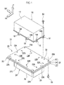
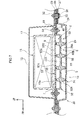
Fig. 1 is a perspective view showing a fuel cell stack and a battery frame that structures a battery mounting structure for a vehicle in accordance with present exemplary embodiments. -
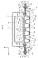
Fig. 2 is a front sectional diagram showing a battery mounting structure for a vehicle in accordance with a first exemplary embodiment. -
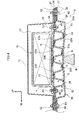
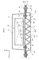
Fig. 3 is a side sectional diagram showing the battery mounting structure for a vehicle in accordance with the first exemplary embodiment. -
Fig. 4 is a side sectional diagram showing a state in which an interference object on a road surface is interfering, from the vehicle body lower side, with a battery frame that structures the battery mounting structure for a vehicle in accordance with the first exemplary embodiment. -
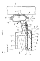
Fig. 5 is a front sectional diagram showing a state when a pole collides with a side face of the vehicle equipped with the battery mounting structure for a vehicle in accordance with the first exemplary embodiment. -
Fig. 6 is a side sectional diagram showing a battery mounting structure for a vehicle in accordance with a second exemplary embodiment. -
Fig. 7 is a side sectional diagram showing a battery mounting structure for a vehicle in accordance with the second exemplary embodiment. -
Fig. 8 is a side sectional diagram showing a battery mounting structure for a vehicle in accordance with a third exemplary embodiment. -
Fig. 9 is a side sectional diagram showing a battery mounting structure for a vehicle in accordance with the third exemplary embodiment. -
Fig. 10 is a perspective diagram showing a partial magnification of a battery frame that structures a battery mounting structure for a vehicle in accordance with a Reference Example. - Herebelow, exemplary embodiments relating to the present invention are described in detail in accordance with the drawings. For convenience of description, the arrow UP that is shown where appropriate in the drawings represents a vehicle body upward direction, the arrow FR represents a vehicle body forward direction, and the arrow OUT represents a vehicle width direction outer side. In the following descriptions, where the directions up, down, front, rear, left and right are used without being particularly specified, the same represent up and down in the vehicle body up-and-down direction, the front and rear in the vehicle body front-and-rear direction, and left and right in the vehicle body left-and-right direction (the vehicle width direction).
- A first exemplary embodiment is described. As shown in
Fig. 1 andFig. 2 , a battery mounting structure for avehicle 10 according to the present exemplary embodiment, which is employed in a vehicle such as an electric car or the like, is disposed at the vehicle body lower side of afloor panel 12 fabricated of metal, which structures a vehicle body floor. The battery mounting structure for avehicle 10 includes a battery frame (a stack frame) 20 fabricated of a fiber-reinforced resin, which supports afuel cell stack 16 that serves as a battery from the vehicle body lower side thereof. - Under members (side frames) 14 are disposed at a lower face of the
floor panel 12. The undermembers 14 structure a vehicle body framework structure that extends in the vehicle front-and-rear direction. The undermembers 14 are formed of metal with substantial hat shapes in a sectional view.Flange portions 15 of theunder members 14 that project in the vehicle width direction are joined, by welding or the like, to the lower face of thefloor panel 12 at each of two outer side end portions thereof in the vehicle width direction. -
Attachment holes 14A that penetrate through theunder members 14 are formed in plural numbers along the length direction of the under members 14 (the vehicle front-and-rear direction). The attachment holes 14A are for the insertion offlange bolts 50, which are described below. Welded nuts 52 are provided at the upper faces of theunder members 14, coaxially with the attachment holes 14A. - An
exterior part 17 of thefuel cell stack 16 is formed of metal (or may be formed of resin) in a rectangular box shape.Projection portions 18 are formed integrally at plural predetermined positions of lower end peripheral edge portions of theexterior part 17. Theprojection portions 18 project to the outer sides.Penetrating holes 18A are formed in theprojection portions 18 for insertion of theflange bolts 50. - As shown in
Fig. 1 to Fig. 3 , thebattery frame 20 includes anupper frame 22 in a flat board shape, alower frame 24 in a tray shape, and apartition member 30. Theupper frame 22 serves as a battery frame upper member, thelower frame 24 serves as a battery frame lower member, and thepartition member 30 serves as an intermediate member that is interposed between theupper frame 22 and thelower frame 24. - The
lower frame 24 includes a flat board-shapedfloor portion 25, flat board-shapedside wall portions 26 and flat board-shapedprojection portions 27. Theside wall portions 26 integrally stand at least from both of vehicle width direction end portions of thefloor portion 25. Theprojection portions 27 integrally project to the vehicle width direction outer sides from upper end portions of theside wall portions 26. Thepartition member 30 includes amain body portion 32, which is formed substantially in a waveform shape in a side view seen in the vehicle width direction. - The
main body portion 32 extends in the vehicle width direction (a length direction of themain body portion 32 is in the vehicle width direction). Themain body portion 32 is structured by a plural number (eight in the illustrated structure) ofvertical walls 32A, and flat board-shapedupper connecting portions 32B (upper end portions) and lower connectingportions 32C (lower end portions). Thevertical walls 32A are arranged in a row in the vehicle body front-and-rear direction in a plan view. Alternating between upper and lower, the upper connectingportions 32B integrally connect upper end portions of thevertical walls 32A to one another and the lower connectingportions 32C integrally connect lower end portions of thevertical walls 32A to one another. (Thevertical walls 32A are formed between the upper connectingportions 32B and the lower connectingportions 32C.) - In this structure, as shown in
Fig. 3 , neighboringvertical walls 32A (although standing substantially vertically) are inclined in opposite directions to one another at matching small angles in a side view. The upper connectingportions 32B and the lower connectingportions 32C connect, respectively, the upper end portions and the lower end portions of thevertical walls 32A to one another at the sides at which the spacings between thevertical walls 32A are smaller. In the case of thepartition member 30 shown in the drawings, three of the upper connectingportions 32B are provided and four of the lower connectingportions 32C are provided. - Upper faces (flat surfaces) of the upper connecting
portions 32B abut against or are disposed close to alower face 22A of theupper frame 22. Lower faces (flat surfaces) of the lower connectingportions 32C abut against or are disposed close to anupper face 24A of thelower frame 24. The upper faces of the upper connectingportions 32B are joined to thelower face 22A of theupper frame 22 with an adhesive G, and the lower faces of the lower connectingportions 32C are joined to theupper face 24A of thelower frame 24 with the adhesive G. - The
partition member 30 further includes flat board-shapedprojection portions 34 that integrally project to the vehicle width direction outer sides at least from outer side end portions in the vehicle width direction of themain body portion 32. Theprojection portions 34 of thepartition member 30 are joined to theprojection portions 27 of thelower frame 24 with the adhesive G.Outer periphery portions 23 of theupper frame 22, which are vehicle width direction outer side end portions thereof, are joined to theprojection portions 34 with the adhesive G. - Thus, the
battery frame 20 is structured with a rectangular closed cross section structure. Within the closed cross section (enclosure) of thebattery frame 20, a plural number (nine in the illustrated structure) of space regions S are partitioned by the partition member 30 (i.e., thevertical walls 32A spanning up and down between theupper frame 22 and the lower frame 24). Thus, the space regions S are formed with substantially the same shapes in a side view (and substantially the same volumes), and are arrayed in a single row in the vehicle front-and-rear direction. - If the upper faces of the upper connecting
portions 32B and the lower faces of the lower connectingportions 32C are disposed close to, respectively, thelower face 22A of theupper frame 22 and theupper face 24A of the lower frame 24 (for example, being separated by 0.5 mm), these faces can be joined by appropriate regulation of thickness of the adhesive G (specifying the thickness). - As shown in
Fig. 2 , each of two end faces in the vehicle width direction of thevertical walls 32A abuts against or is disposed close to the inner faces of theside wall portions 26. These faces may be not joined or may be joined. Herebelow, theprojection portions 27,projection portions 34 andouter periphery portions 23 that are joined to one another are referred to asflange portions 28 of the battery frame 20 (seeFig. 1 andFig. 2 ). Theflange portions 28 constitute portions of thebattery frame 20 that are fixed to the undermembers 14. - As shown in
Fig. 1 to Fig. 3 , penetratingholes 22B are formed at plural predetermined positions of theupper frame 22, excluding theouter periphery portions 23. Plural attachment holes 34B are formed at proximal ends (near thevertical walls 32A) of theprojection portions 34 of thepartition member 30. The attachment holes 34B communicate with the penetratingholes 22B.Tubular collar members 36 that are fabricated of metal are insertedly installed coaxially in the penetratingholes 22B and the attachment holes 34B. - That is,
flange nuts 48 are joined by adhesive to the lower faces of the proximal ends of theprojection portions 34, coaxially with the attachment holes 34B, and thecollar members 36 are integrally and coaxially provided at upper faces of the flange nuts 48. Thus, thecollar members 36 are insertedly installed in the attachment holes 34B and the penetratingholes 22B in association with the joining of theflange nuts 48 to theprojection portions 34. - Hence, the fuel cell stack 16 (the projection portions 18) is placed on an
upper face 22C of theupper frame 22 such that the penetratingholes 18A of theprojection portions 18 communicate with penetrating holes 36A of thecollar members 36. Theflange bolts 50 are inserted into the penetratingholes 18A and the penetrating holes 36A from the vehicle body upper side thereof, and are screwed into the flange nuts 48. Thus, thefuel cell stack 16 is fastened and fixed to the battery frame 20 (the upper frame 22). At this time, a cavity region T is formed between afloor face 17A of theexterior part 17 and theupper face 22C of theupper frame 22. - Plural numbers of penetrating
holes flange portions 28, which is to say in theouter periphery portions 23 of theupper frame 22, theprojection portions 34 of thepartition member 30 and theprojection portions 27 of thelower frame 24. The penetratingholes flange bolts 50.Tubular collar members 38 that are fabricated of metal are insertedly installed coaxially in the penetratingholes - Thus, by the
flange bolts 50 being inserted into penetrating holes 38A of thecollar members 38 and the attachment holes 14A from the vehicle body lower side thereof and screwed into the welded nuts 52, theflange portions 28 of thebattery frame 20 are fastened and fixed to the undermembers 14. - As shown in
Fig. 2 , outer side end portions in the vehicle width direction of thefloor panel 12 are formed as inflectedportions 12A, which are inflected upward. Theinflected portions 12A are joined by welding or the like toinner panels 42 ofrockers 40 that are fabricated of metal. Eachrocker 40 is structured by theinner panel 42, anouter panel 44 and areinforcement 46. Theinner panel 42 is formed in a substantial hat shape in cross section. Theouter panel 44 is formed in a substantial hat shape in cross section. Thereinforcement 46 is disposed between theinner panel 42 and theouter panel 44, and is formed in a substantial hat shape in cross section. - That is, an
upper flange portion 46A of thereinforcement 46 is joined to anupper flange portion 42A of theinner panel 42, and anupper flange portion 44A of theouter panel 44 is joined to theupper flange portion 46A. Further, alower flange portion 46B of thereinforcement 46 is joined to alower flange portion 42B of theinner panel 42, and alower flange portion 44B of theouter panel 44 is joined to thelower flange portion 46B. - Thus, in the
rocker 40, respective closed cross section structures are structured by theinner panel 42 and thereinforcement 46 and by thereinforcement 46 and theouter panel 44. - Now, operations of the battery mounting structure for a
vehicle 10 according to the first exemplary embodiment as described above are described. Operations are described for: a case in which, as shown inFig. 4 , an interference object N on a road surface such as a rock or the like that is sticking up interferes with thelower frame 24 of thebattery frame 20 during, for example, running of the vehicle on a poor road; and a case in which, as shown inFig. 5 , the vehicle has a side collision with a cylindrical pole P that extends in the vertical direction. - As shown in
Fig. 4 , when the interference object N on the road surface interferes with thelower frame 24 of thebattery frame 20, the battery frame 20 (the lower frame 24) resiliently deforms so as to bow upward. However, thebattery frame 20 is provided with thepartition member 30 that is formed in a substantial waveform shape in side view within the closed cross section (enclosure) that is structured by thelower frame 24 and theupper frame 22. - More specifically, the upper faces of the upper connecting
portions 32B and the lower faces of the lower connectingportions 32C of the partition member 30 (the main body portion 32) are joined by the adhesive G to, respectively, thelower face 22A of theupper frame 22 and theupper face 24A of the lower frame 24 (i.e., theupper frame 22 and thelower frame 24 are connected by the pluralvertical walls 32A. - Therefore, when the battery frame 20 (the lower frame 24) is resiliently deformed so as to bow upward, the partition member 30 (the main body portion 32) braces between the
lower frame 24 and theupper frame 22, and theupper frame 22 provides resistance to tension forces towards the outer sides. - In particular, because the upper faces of the upper connecting
portions 32B and the lower faces of the lower connectingportions 32C of the partition member 30 (the main body portion 32) are both formed as flat surfaces and joining areas thereof to thelower face 22A of theupper frame 22 and theupper face 24A of thelower frame 24 are assuredly large, joining strengths thereof are improved. - Therefore, strength (stiffness) of the
battery frame 20 with respect to a load inputted from the vehicle body lower side by the interference object N on the road surface may be improved. That is, the resilient deformation may be accordingly suppressed by both thelower frame 24 and the overall closed cross section structure of thebattery frame 20. - Because the cavity region T is formed between the
upper face 22C of theupper frame 22 and thefloor face 17A of theexterior part 17, even if thebattery frame 20 resiliently deforms slightly so as to bow upward, interference (abutting) of theupper face 22C with the floor face 17A may be suppressed or prevented. Thus, even when an interference object N on a road surface interferes with the lower portions of the vehicle, thefuel cell stack 16 may be protected from a load that is inputted as a result. - Alternatively, as shown in
Fig. 5 , when the vehicle has a side collision with the pole P, a large impact load F is inputted to therocker 40. As a result, therocker 40 plastically deforms while moving to an inner side in the vehicle width direction thereof, and a portion of the inputted impact load F is transmitted to thefloor panel 12 and thebattery frame 20. - Now, the
battery frame 20 is formed with a closed cross section structure, and the pluralvertical walls 32A that extend in the vehicle width direction and connect up-and-down between theupper frame 22 and thelower frame 24 are provided inside this closed cross section (enclosure). That is, within the closed cross section of thebattery frame 20, the plural space regions S that are arranged in a row in the vehicle body front-and-rear direction in side view are partitioned by the pluralvertical walls 32A that stand substantially vertically (seeFig. 3 ). - Therefore, a cross-sectional moment of inertia of the
battery frame 20 may be increased, and cross-sectional deformation (deformation that flexes in the vehicle body up-and-down direction) of theupper frame 22 andlower frame 24 may be suppressed. That is, cross-sectional strength of thebattery frame 20 may be improved. In particular, collision resistance performance with respect to impact loads inputted in the vehicle width direction may be improved. - Therefore, when a side collision of the vehicle occurs, even though a bending moment M (and torque) is inputted to the proximal end of the
flange portion 28 by the undermember 14 that has been subjected to a portion of the impact load F via thefloor panel 12, a deformation bending the proximal end of theflange portion 28 upward may be suppressed. - Thus, when the vehicle has a side collision, the portion of an impact load F that is inputted to the
flange portion 28 is efficiently transmitted to the battery frame 20 (to thevertical walls 32A of the main body portion 32), and thefuel cell stack 16 may be protected from the impact load F. Note that, because thepartition member 30 is formed of a fiber-reinforced resin material, similarly to theupper frame 22 and thelower frame 24, there is also an advantage in that an increase in weight of the vehicle may be moderated. - Now, a second exemplary embodiment is described. Portions that are the same as in the above-described first exemplary embodiment are assigned the same reference numerals and are not described in detail (nor operations thereof).
- As shown in
Fig. 6 andFig. 7 , themain body portion 32 of thepartition member 30 according to the second exemplary embodiment includes asupport member 33 inside the closed cross section that is disposed to be parallel with theupper frame 22 and thelower frame 24. At least outer side end portions in the vehicle width direction of thesupport member 33 serve as theprojection portions 34.Protrusion portions 35 are plurally formed at an upper face and a lower face of thesupport member 33. Theprotrusion portions 35 extend in the vehicle width direction (a length direction thereof is the vehicle width direction), and are formed in isosceles trapezoid shapes in a side sectional view. - The
protrusion portions 35 shown inFig. 6 do not protrude at the same positions above and below. Theprotrusion portions 35 at the lower face side (or upper face side) protrude at gaps between theprotrusion portions 35 at the upper face side (or lower face side), which are in a row in the vehicle front-and-rear direction. In contrast, theprotrusion portions 35 shown inFig. 7 protrude at the same positions above and below. Theprotrusion portions 35 at the lower face side (or upper face side) protrude at the opposite sides, upper and lower, from theprotrusion portions 35 at the upper face side (or lower face side), which are in a row in the vehicle front-and-rear direction. - Upper end faces 35A (upper end portions) of the
protrusion portions 35 protruding from the upper face of thesupport member 33 and lower end faces 35B (lower end portions) of theprotrusion portions 35 protruding from the lower face of thesupport member 33 are joined with an adhesive G to, respectively, thelower face 22A of theupper frame 22 and theupper face 24A of thelower frame 24. - Side walls of the
protrusion portions 35 facing in the vehicle body front-and-rear direction (that stand substantially vertically) serve as thevertical walls 32A. Thus, the interior of the closed cross section (the enclosure) is partitioned into plural space regions S by theprotrusion portions 35. In this second exemplary embodiment, the interior of the closed cross section is partitioned in the vehicle body up-and-down direction as well as in the vehicle body front-and-rear direction. Furthermore, because the upper end faces 35A and the lower end faces 35B are flat surfaces, similarly to the upper connectingportions 32B and lower connectingportions 32C of the first exemplary embodiment described above, joining areas may be assured. - Now, a third exemplary embodiment is described. Portions that are the same as in the above-described first exemplary embodiment are assigned the same reference numerals and are not described in detail (nor operations thereof).
- As shown in
Fig. 8 andFig. 9 , themain body portion 32 included in thepartition member 30 according to the third exemplary embodiment is formed in a waveform shape in a side view. That is,upper end portions 32D andlower end portions 32E of themain body portion 32 shown inFig. 8 are respectively formed in circular arc shapes in a side view. Theupper end portions 32D andlower end portions 32E of themain body portion 32 shown inFig. 9 are respectively formed in isosceles triangle shapes in a side sectional view. - That is, in the
partition member 30 according to the third exemplary embodiment, theupper end portions 32D and thelower end portions 32E of themain body portion 32 are joined with the adhesive G to, respectively, thelower face 22A of theupper frame 22 and theupper face 24A of thelower frame 24. Theupper end portions 32D andlower end portions 32E are not formed with flat surfaces (i.e., joining regions of theupper end portions 32D and thelower end portions 32E are formed in linear shapes in the vehicle width direction). - However, in the
partition member 30 according to the third exemplary embodiment, numbers of theupper end portions 32D andlower end portions 32E that are joined with an adhesive G to, respectively, thelower face 22A of theupper frame 22 and theupper face 24A of thelower frame 24 may be increased compared to the first exemplary embodiment described above. Therefore, a reduction in strength of thebattery frame 20 may be moderated. - Finally, a Reference Example is described. Portions that are the same as in the above-described first exemplary embodiment are assigned the same reference numerals and are not described in detail (nor operations thereof).
- As shown in
Fig. 10 , in the Reference Example,vertical walls 54 protrude from thelower face 22A of theupper frame 22. Thevertical walls 54 protrude in a grid pattern that extends in the vehicle body front-and-rear direction and in the vehicle width direction. - In addition,
vertical walls 56 protrude from theupper face 24A of thelower frame 24. Thevertical walls 56 protrude in the grid pattern that extends in the vehicle body front-and-rear direction and in the vehicle width direction. Lower end faces of thevertical walls 54 and upper end faces of thevertical walls 56 abut against or are disposed close to one another, and are joined with an adhesive G. - According to this structure, both cross-sectional strength of the
battery frame 20 with respect to impact loads inputted in the vehicle width direction and cross-sectional strength of thebattery frame 20 with respect to impact loads inputted in the vehicle body front-and-rear direction may be improved. That is, both impact loads inputted when the vehicle has a side collision and impact loads inputted when the vehicle has a front collision or a rear collision are efficiently transmitted to thebattery frame 20. Thus, collision resistance performance with respect both to side collisions of the vehicle and to front collisions and rear collisions may be improved. - A structure is also possible in which only the
vertical walls 54 protrude from thelower face 22A of theupper frame 22, to a height that reaches theupper face 24A of thelower frame 24, and a structure is possible in which only thevertical walls 56 protrude from theupper face 24A of thelower frame 24, to a height that reaches thelower face 22A of theupper frame 22. - The
upper frame 22 and thelower frame 24 may be connected by vertical walls that are separate bodies arranged in the grid pattern (not shown in the drawings). Further, thevertical walls - Hereabove, the battery mounting structure for a
vehicle 10 according to the present exemplary embodiments is described by reference to the drawings. However, the battery mounting structure for avehicle 10 according to the present exemplary embodiments is not limited to the structures shown in the drawings; suitable design modifications are possible without deviating from the scope of the present invention. For example, thecollar members 36 may be structured as separate bodies from the flange nuts 48. - Further, the upper connecting
portions 32B and lower connectingportions 32C, upper end faces 35A and lower end faces 35B, andupper end portions 32D andlower end portions 32E may be structures that are not joined to, respectively, thelower face 22A of theupper frame 22 and theupper face 24A of thelower frame 24. However, structures that are joined are more desirable with regard to improving the strength of thebattery frame 20. - When these portions/faces are joined, joining by rivets, welding or the like is possible. However, joining by an adhesive G is more desirable in being adaptable to cases in which there are gaps between these portions/faces and, respectively, the
lower face 22A of theupper frame 22 and theupper face 24A of thelower frame 24. Further yet, thebattery frame 20 according to the present exemplary embodiment is not limited to being a structure that supports thefuel cell stack 16. - In the first to third exemplary embodiments described above, the
vertical walls 32A of themain body portion 32 of thepartition member 30 extend in the vehicle width direction (the length direction thereof is the vehicle width direction). However, structures are possible in which thevertical walls 32A extend in the vehicle body front-and-rear direction (the length direction thereof is the vehicle body front-and-rear direction). In this case, collision resistance performance of thebattery frame 20 with respect to front collisions, rear collisions and the like of the vehicle may be improved.
Claims (5)
- A battery mounting structure for a vehicle, comprising:a battery frame upper member fabricated of fiber-reinforced resin to which a battery is attached, the battery being disposed at a vehicle body lower side of a floor panel;a battery frame lower member fabricated of fiber-reinforced resin that, with the battery frame upper member, structures a closed cross section structure; andan intermediate member fabricated of fiber-reinforced resin that is interposed between the battery frame upper member and the battery frame lower member, the intermediate member being provided with:a plurality of upper end portions that abut against or are disposed close to a lower face of the battery frame upper member, anda plurality of lower end portions that abut against or are disposed close to an upper face of the battery frame lower member.
- The battery mounting structure for a vehicle according to claim 1, wherein the upper end portions and the lower end portions of the intermediate member are joined to, respectively, the lower face of the battery frame upper member and the upper face of the battery frame lower member by adhesive.
- The battery mounting structure for a vehicle according to claim 1 or claim 2, wherein the upper end portions and the lower end portions of the intermediate member are respectively formed as flat surfaces.
- The battery mounting structure for a vehicle according to any one of claims 1 to 3, wherein vertical walls are formed between the upper end portions and the lower end portions of the intermediate member.
- The battery mounting structure for a vehicle according to claim 4, wherein the vertical walls extend in a vehicle width direction.
Applications Claiming Priority (1)
| Application Number | Priority Date | Filing Date | Title |
|---|---|---|---|
| PCT/JP2012/076731 WO2014061109A1 (en) | 2012-10-16 | 2012-10-16 | Cell installation structure for vehicle |
Publications (3)
| Publication Number | Publication Date |
|---|---|
| EP2910394A1 true EP2910394A1 (en) | 2015-08-26 |
| EP2910394A4 EP2910394A4 (en) | 2015-10-28 |
| EP2910394B1 EP2910394B1 (en) | 2018-12-26 |
Family
ID=50487698
Family Applications (1)
| Application Number | Title | Priority Date | Filing Date |
|---|---|---|---|
| EP12886620.9A Active EP2910394B1 (en) | 2012-10-16 | 2012-10-16 | Cell installation structure for vehicle |
Country Status (5)
| Country | Link |
|---|---|
| US (1) | US9281505B2 (en) |
| EP (1) | EP2910394B1 (en) |
| JP (1) | JP5783337B2 (en) |
| CN (1) | CN104884288B (en) |
| WO (1) | WO2014061109A1 (en) |
Cited By (15)
| Publication number | Priority date | Publication date | Assignee | Title |
|---|---|---|---|---|
| DE102016216050A1 (en) | 2016-08-25 | 2018-03-15 | Volkswagen Aktiengesellschaft | Battery assembly and vehicle with such a battery assembly |
| WO2018149762A1 (en) * | 2017-02-17 | 2018-08-23 | Mubea Carbo Tech Gmbh | Battery structure and protector |
| WO2018166762A1 (en) * | 2017-03-16 | 2018-09-20 | Audi Ag | Battery for a motor vehicle and motor vehicle |
| FR3071789A1 (en) * | 2017-10-04 | 2019-04-05 | Valeo Systemes Thermiques | BATTERY SUPPORT HOUSING |
| DE102017221345A1 (en) * | 2017-11-28 | 2019-05-29 | Thyssenkrupp Ag | Hybrid underbody protection device for battery case |
| WO2019105746A1 (en) * | 2017-11-28 | 2019-06-06 | Thyssenkrupp Steel Europe Ag | Battery housing for a vehicle |
| WO2019202018A1 (en) * | 2018-04-20 | 2019-10-24 | Thyssenkrupp Steel Europe Ag | Underrun-protection arrangement for a vehicle-battery arrangement, vehicle-battery arrangement, method for producing an underrun-protection arrangement, and method for producing a vehicle-battery arrangement |
| EP3587841A1 (en) * | 2018-06-27 | 2020-01-01 | Nio Nextev Limited | Floating nut, battery assembly and vehicle |
| WO2020025256A1 (en) * | 2018-08-03 | 2020-02-06 | Bayerische Motoren Werke Aktiengesellschaft | Assembly for securing a vehicle battery on a body of a motor vehicle, and method for mounting a vehicle battery in a motor vehicle |
| US10589614B2 (en) | 2018-01-10 | 2020-03-17 | Volvo Car Corporation | Reinforcement structure |
| DE102020103078A1 (en) * | 2020-02-06 | 2021-03-18 | Audi Aktiengesellschaft | Vehicle with an energy storage device |
| CN113085586A (en) * | 2019-12-19 | 2021-07-09 | 大众汽车股份公司 | High voltage battery for vehicle |
| DE102020212682A1 (en) | 2020-10-07 | 2022-04-07 | Volkswagen Aktiengesellschaft | High-voltage battery for an electrically powered vehicle |
| DE102022116978B3 (en) | 2022-07-07 | 2023-10-05 | Dr. Ing. H.C. F. Porsche Aktiengesellschaft | Underrun protection device and method for producing an underrun protection device |
| DE102022131035B3 (en) | 2022-11-23 | 2024-04-25 | Bayerische Motoren Werke Aktiengesellschaft | Housing base for a storage housing of an energy storage device of an electrically powered motor vehicle |
Families Citing this family (103)
| Publication number | Priority date | Publication date | Assignee | Title |
|---|---|---|---|---|
| DE102010051745B4 (en) * | 2010-11-19 | 2012-06-28 | Benteler Automobiltechnik Gmbh | Car with protection component |
| JP6135754B2 (en) * | 2013-04-12 | 2017-05-31 | 日産自動車株式会社 | Non-contact power feeding device |
| DE102013006702A1 (en) * | 2013-04-18 | 2014-10-23 | Volkswagen Aktiengesellschaft | Battery arrangement in a two-lane vehicle |
| FR3010383B1 (en) * | 2013-09-06 | 2017-05-05 | Plastic Omnium Cie | FLOOR OF MOTOR VEHICLE WITH UPPER REINFORCING SKIN AND OPENING ACCESSIBILITY TO HOLLOW BODIES |
| JP5870992B2 (en) * | 2013-12-25 | 2016-03-01 | トヨタ自動車株式会社 | Battery mounting structure for vehicles |
| JP5900481B2 (en) * | 2013-12-25 | 2016-04-06 | トヨタ自動車株式会社 | Vehicle panel structure |
| JP5811168B2 (en) * | 2013-12-25 | 2015-11-11 | トヨタ自動車株式会社 | Battery mounting structure for vehicles |
| JP6213331B2 (en) * | 2014-03-24 | 2017-10-18 | トヨタ自動車株式会社 | Electric vehicle |
| DE102014108160A1 (en) * | 2014-06-11 | 2015-12-17 | Dr. Ing. H.C. F. Porsche Aktiengesellschaft | Underbody unit for a motor vehicle |
| JP6177744B2 (en) * | 2014-09-03 | 2017-08-09 | 豊田鉄工株式会社 | Body frame structure |
| DE112015004834T5 (en) * | 2014-10-24 | 2017-07-06 | Aisin Keikinzoku Co., Ltd. | PROTECTION UNDER ARRANGEMENT |
| JP6210049B2 (en) * | 2014-11-04 | 2017-10-11 | トヨタ自動車株式会社 | vehicle |
| DE102015101096A1 (en) * | 2015-01-27 | 2016-07-28 | Dr. Ing. H.C. F. Porsche Aktiengesellschaft | Battery support structure |
| US10319964B2 (en) * | 2015-01-28 | 2019-06-11 | Ford Global Technologies, Llc | Battery array frame including frame rail insert |
| US10358169B2 (en) * | 2015-03-06 | 2019-07-23 | Ford Global Technologies, Llc | Coverless battery assembly for electrified vehicle |
| JP6681912B2 (en) * | 2015-03-17 | 2020-04-15 | オートテック・エンジニアリング・ソシエダッド・リミターダAutotech Engineering, S.L. | Motor vehicle lockers and vehicles equipped with such rockers |
| DE102015111749A1 (en) * | 2015-07-20 | 2017-01-26 | Dr. Ing. H.C. F. Porsche Aktiengesellschaft | Battery device and method |
| US9533600B1 (en) | 2015-09-03 | 2017-01-03 | GM Global Technology Operations LLC | Structurally integrated propulsion battery |
| JP6118381B2 (en) * | 2015-09-30 | 2017-04-19 | 富士重工業株式会社 | Automotive battery |
| JP6101768B1 (en) * | 2015-09-30 | 2017-03-22 | 富士重工業株式会社 | Collision load relaxation structure |
| DE102015121965A1 (en) * | 2015-12-16 | 2017-06-22 | Dr. Ing. H.C. F. Porsche Aktiengesellschaft | battery assembly |
| JP6215975B2 (en) * | 2016-01-12 | 2017-10-18 | 本田技研工業株式会社 | Battery fixing structure |
| US9673433B1 (en) * | 2016-01-26 | 2017-06-06 | Ford Global Technologies, Llc | Deformable battery pack enclosure |
| DE102016203209B4 (en) * | 2016-02-29 | 2020-11-19 | Ford Global Technologies, Llc | At least partially electrically operated motor vehicle |
| DE102016204223A1 (en) * | 2016-03-15 | 2017-09-21 | Bayerische Motoren Werke Aktiengesellschaft | motor vehicle |
| JP6512162B2 (en) * | 2016-04-21 | 2019-05-15 | トヨタ自動車株式会社 | Vehicle battery mounting structure |
| DE102016207231B4 (en) * | 2016-04-28 | 2022-05-05 | Bayerische Motoren Werke Aktiengesellschaft | Arrangement of an electrical high-voltage energy store on a motor vehicle |
| EP3261149B1 (en) * | 2016-06-20 | 2021-09-15 | Magna Steyr Fahrzeugtechnik AG & Co KG | Mounting assembly |
| JP6686758B2 (en) * | 2016-07-19 | 2020-04-22 | トヨタ自動車株式会社 | Battery case |
| JP6319672B2 (en) * | 2016-07-21 | 2018-05-09 | マツダ株式会社 | Body reinforcement structure |
| DE102016214974A1 (en) * | 2016-08-11 | 2018-02-15 | Thyssenkrupp Ag | battery case |
| US10632857B2 (en) | 2016-08-17 | 2020-04-28 | Shape Corp. | Battery support and protection structure for a vehicle |
| CN206201948U (en) * | 2016-08-31 | 2017-05-31 | 比亚迪股份有限公司 | A kind of Vehicular tray component, Vehicular battery inclusion and automobile |
| US20180065461A1 (en) * | 2016-09-07 | 2018-03-08 | Thunder Power New Energy Vehicle Development Company Limited | Cross member in the floor with special geometry for mounting the battery pack |
| US10431791B2 (en) * | 2016-11-01 | 2019-10-01 | Ford Global Technologies, Llc | Traction battery pack shield and shielding method |
| US10381621B2 (en) * | 2016-11-01 | 2019-08-13 | Ford Global Technologies, Llc | Traction battery energy absorbing method and assembly |
| JP6813348B2 (en) * | 2016-12-14 | 2021-01-13 | 株式会社Subaru | Car vehicle |
| EP3566253B1 (en) | 2017-01-04 | 2022-12-28 | Shape Corp. | Battery support structure for a vehicle |
| JP6475270B2 (en) * | 2017-01-20 | 2019-02-27 | 株式会社Subaru | Car |
| US9926017B1 (en) * | 2017-01-24 | 2018-03-27 | GM Global Technology Operations LLC | Structural enhancements of an electric vehicle |
| DE102017103653A1 (en) | 2017-02-22 | 2018-08-23 | Thyssenkrupp Ag | Battery housing for a vehicle battery and chassis for an electric vehicle |
| WO2018213383A1 (en) | 2017-05-16 | 2018-11-22 | Shape Corp. | Vehicle battery tray with integrated battery retention and support features |
| US10886513B2 (en) | 2017-05-16 | 2021-01-05 | Shape Corp. | Vehicle battery tray having tub-based integration |
| JP6541724B2 (en) * | 2017-07-10 | 2019-07-10 | 株式会社Subaru | Car vehicle |
| DE102017117726A1 (en) * | 2017-08-04 | 2019-02-07 | enfas GmbH | Housing device for energy storage systems |
| CN111108015A (en) | 2017-09-13 | 2020-05-05 | 形状集团 | Vehicle battery tray with tubular peripheral wall |
| JP6582025B2 (en) * | 2017-09-14 | 2019-09-25 | 本田技研工業株式会社 | Battery unit |
| JP7123537B2 (en) * | 2017-09-19 | 2022-08-23 | 株式会社Fts | battery case |
| US10494034B2 (en) * | 2017-09-25 | 2019-12-03 | Ford Global Technologies, Llc | Vehicle frame assembly |
| WO2019071013A1 (en) * | 2017-10-04 | 2019-04-11 | Shape Corp. | Battery tray floor assembly for electric vehicles |
| DE102017217960A1 (en) * | 2017-10-09 | 2019-04-11 | Bayerische Motoren Werke Aktiengesellschaft | Recording medium for an energy storage module with multiple energy storage cells |
| DE102017126949A1 (en) * | 2017-11-16 | 2019-05-16 | Dr. Ing. H.C. F. Porsche Aktiengesellschaft | Battery device for an at least partially electrically operated motor vehicle |
| JP6859933B2 (en) * | 2017-11-17 | 2021-04-14 | トヨタ自動車株式会社 | Vehicle battery case and its manufacturing method |
| JP6885316B2 (en) * | 2017-12-07 | 2021-06-16 | トヨタ自動車株式会社 | Retention structure for mounted parts on the floor panel |
| JP2019114469A (en) * | 2017-12-25 | 2019-07-11 | トヨタ自動車株式会社 | Fuel cell vehicle |
| JP7155168B2 (en) * | 2018-01-30 | 2022-10-18 | 三洋電機株式会社 | Power supply and electric vehicle equipped with power supply |
| JP6655638B2 (en) * | 2018-02-15 | 2020-02-26 | 本田技研工業株式会社 | Body structure |
| JP7095307B2 (en) * | 2018-02-23 | 2022-07-05 | トヨタ自動車株式会社 | Vehicle undercarriage |
| EP3759761A4 (en) | 2018-03-01 | 2021-09-08 | Shape Corp. | Cooling system integrated with vehicle battery tray |
| JP6996352B2 (en) * | 2018-03-06 | 2022-01-17 | トヨタ自動車株式会社 | Vehicle lower body structure |
| JP7006390B2 (en) * | 2018-03-09 | 2022-01-24 | トヨタ自動車株式会社 | Vehicle lower body structure |
| JP6988590B2 (en) * | 2018-03-09 | 2022-01-05 | トヨタ自動車株式会社 | Vehicle rear structure |
| JP7006771B2 (en) * | 2018-03-13 | 2022-01-24 | 日本製鉄株式会社 | Floor structure |
| US11688910B2 (en) | 2018-03-15 | 2023-06-27 | Shape Corp. | Vehicle battery tray having tub-based component |
| DE102018106399A1 (en) * | 2018-03-19 | 2019-09-19 | Muhr Und Bender Kg | Housing arrangement for receiving electrical storage means and method for producing a housing assembly |
| CN108528542B (en) * | 2018-03-27 | 2019-08-23 | 吉利汽车研究院(宁波)有限公司 | A kind of battery protecting plate and vehicle |
| JP6965812B2 (en) * | 2018-04-12 | 2021-11-10 | トヨタ自動車株式会社 | Battery pack |
| DE102018109508A1 (en) * | 2018-04-20 | 2019-10-24 | Bayerische Motoren Werke Aktiengesellschaft | Fastening device for fastening a high-voltage accumulator housing to a shell component of a motor vehicle and high-voltage accumulator housing |
| US10559793B2 (en) * | 2018-05-17 | 2020-02-11 | Ford Global Technologies, Llc | Battery array retention method and assembly |
| DE102018210121A1 (en) * | 2018-06-21 | 2019-12-24 | Volkswagen Aktiengesellschaft | Battery housing and motor vehicle with such a battery housing |
| JP7040338B2 (en) * | 2018-07-25 | 2022-03-23 | トヨタ自動車株式会社 | Floor structure with vehicle batteries |
| JP6881404B2 (en) * | 2018-08-13 | 2021-06-02 | マツダ株式会社 | Lower body structure |
| US10494030B1 (en) * | 2018-08-20 | 2019-12-03 | Ford Global Technologies, Llc | Collapsible battery pack support assembly and supporting method |
| US11059361B2 (en) * | 2018-09-04 | 2021-07-13 | Ford Global Technologies, Llc | High voltage battery pack support and isolation for electrified vehicles |
| US10559794B1 (en) * | 2018-10-26 | 2020-02-11 | Byton Limited | Battery sealing enclosure |
| WO2020102377A1 (en) * | 2018-11-13 | 2020-05-22 | Vignesh Sekar | Electric vehicle battery pack having bottom strike shield |
| CN111192985A (en) * | 2018-11-15 | 2020-05-22 | 宁德时代新能源科技股份有限公司 | A box and battery package for battery package |
| DE102018132255A1 (en) * | 2018-12-14 | 2020-06-18 | Bayerische Motoren Werke Aktiengesellschaft | Energy storage floor assembly for a car body shell |
| US10476061B1 (en) * | 2018-12-31 | 2019-11-12 | Chongqing Jinkang New Energy Vehicle Co., Ltd. | Electric vehicle cabin floor structure |
| DE102019106241A1 (en) * | 2019-03-12 | 2020-09-17 | Benteler Automobiltechnik Gmbh | Battery tray for holding an electrical battery module |
| CN111864131A (en) * | 2019-04-26 | 2020-10-30 | 爱信轻金属株式会社 | Protection structure of battery module |
| DE102019207435A1 (en) * | 2019-05-21 | 2020-11-26 | Volkswagen Aktiengesellschaft | Underrun protection |
| JP7272867B2 (en) | 2019-05-31 | 2023-05-12 | メルセデス・ベンツ グループ アクチェンゲゼルシャフト | frame for electric truck |
| FR3098022B1 (en) * | 2019-06-28 | 2021-05-28 | Faurecia Systemes Dechappement | Electricity storage battery and vehicle |
| JP7181165B2 (en) * | 2019-08-01 | 2022-11-30 | 株式会社神戸製鋼所 | car body structure |
| JP7194094B2 (en) * | 2019-09-10 | 2022-12-21 | 株式会社神戸製鋼所 | Battery case for electric vehicle |
| JP7252877B2 (en) * | 2019-10-18 | 2023-04-05 | 株式会社神戸製鋼所 | battery housing unit |
| KR20210057499A (en) * | 2019-11-12 | 2021-05-21 | 현대자동차주식회사 | Fuel cell vehicle |
| WO2021130523A1 (en) * | 2019-12-24 | 2021-07-01 | Arcelormittal | Protective element for a battery pack of a hybrid or electric vehicle and process for the assembling of a reinforced battery pack |
| JP7238820B2 (en) * | 2020-02-05 | 2023-03-14 | トヨタ自動車株式会社 | In-vehicle structure of battery pack |
| JP2021138187A (en) * | 2020-03-02 | 2021-09-16 | トヨタ自動車株式会社 | Vehicle body lower part structure |
| JP7413844B2 (en) | 2020-03-03 | 2024-01-16 | トヨタ自動車株式会社 | Vehicle undercarriage structure |
| US11975601B2 (en) * | 2020-04-28 | 2024-05-07 | Nissan Motor Co., Ltd. | Electric vehicle floor structure |
| KR20210149483A (en) * | 2020-06-02 | 2021-12-09 | 주식회사 엘지에너지솔루션 | Battery Pack, Electronic Device and Vehicle |
| DE102020119480A1 (en) | 2020-07-23 | 2022-01-27 | Benteler Automobiltechnik Gmbh | vehicle floor assembly |
| JP7396975B2 (en) * | 2020-10-15 | 2023-12-12 | トヨタ自動車株式会社 | vehicle |
| US20220194489A1 (en) * | 2020-12-18 | 2022-06-23 | Optimal, Inc. | Low floor electric vehicle |
| WO2022180675A1 (en) * | 2021-02-24 | 2022-09-01 | 日産自動車株式会社 | Vehicle-mounted battery pack structure |
| CN113246711B (en) * | 2021-06-23 | 2022-08-09 | 东风柳州汽车有限公司 | Battery package mounting structure and back floor assembly |
| CN113707977B (en) * | 2021-08-20 | 2023-04-14 | 上海派能能源科技股份有限公司 | Pole type lithium battery cover plate and pole type lithium battery |
| US20230322306A1 (en) * | 2022-04-06 | 2023-10-12 | Ford Global Technologies, Llc | Traction battery pack protection and load distribution strategies |
| CN115275488A (en) * | 2022-08-24 | 2022-11-01 | 浙江凌骁能源科技有限公司 | Lower box body of battery pack |
| DE102023104735A1 (en) * | 2023-02-27 | 2024-08-29 | Kautex Textron Gmbh & Co. Kg | Underbody protection for motor vehicles, battery housing for a traction battery, traction battery for motor vehicles and motor vehicle with underbody protection |
Family Cites Families (18)
| Publication number | Priority date | Publication date | Assignee | Title |
|---|---|---|---|---|
| US4726707A (en) * | 1983-11-26 | 1988-02-23 | Newton John R | Composite article |
| AU6296699A (en) | 1998-10-09 | 2000-05-01 | American Structural Composites, Inc. | Composite structural building panels and connection systems |
| JP2008155700A (en) * | 2006-12-21 | 2008-07-10 | Toyota Motor Corp | Vehicle body floor part structure |
| US7998299B2 (en) * | 2008-10-01 | 2011-08-16 | The Boeing Company | Method for making composite truss panel having a fluted core |
| JP4856731B2 (en) * | 2009-02-24 | 2012-01-18 | 本田技研工業株式会社 | Body floor structure |
| WO2010137150A1 (en) * | 2009-05-28 | 2010-12-02 | トヨタ自動車株式会社 | Fuel cell system, and vehicle |
| JP5408440B2 (en) * | 2010-01-18 | 2014-02-05 | 三菱自動車工業株式会社 | Battery case for vehicle |
| JP5408441B2 (en) * | 2010-01-18 | 2014-02-05 | 三菱自動車工業株式会社 | Battery case for vehicle |
| EP2599693B1 (en) * | 2010-07-26 | 2015-11-18 | Nissan Motor Co., Ltd | Structure for vehicle body lower portion |
| JP2012084447A (en) * | 2010-10-13 | 2012-04-26 | Mitsubishi Fuso Truck & Bus Corp | Vehicular battery container |
| JP2012089377A (en) * | 2010-10-20 | 2012-05-10 | Mitsubishi Fuso Truck & Bus Corp | Vehicle battery container |
| KR20120044853A (en) * | 2010-10-28 | 2012-05-08 | 현대자동차주식회사 | Battery pack case assembly for electric vehicles using plastic composite |
| DE102010051745B4 (en) | 2010-11-19 | 2012-06-28 | Benteler Automobiltechnik Gmbh | Car with protection component |
| KR101219399B1 (en) * | 2010-11-24 | 2013-01-11 | 기아자동차주식회사 | Integrated High Voltage Battery Case |
| DE102011002650B4 (en) | 2011-01-13 | 2023-12-07 | Ford Global Technologies, Llc | motor vehicle |
| US9331321B2 (en) * | 2011-03-31 | 2016-05-03 | GM Global Technology Operations LLC | Fabric composite support or enclosure for an automotive battery pack |
| JP5513445B2 (en) * | 2011-06-08 | 2014-06-04 | 本田技研工業株式会社 | Vehicle power supply |
| JP5692019B2 (en) * | 2011-11-22 | 2015-04-01 | トヨタ自動車株式会社 | Service hole cover mounting structure and vehicle battery mounting structure including the same |
-
2012
- 2012-10-16 EP EP12886620.9A patent/EP2910394B1/en active Active
- 2012-10-16 CN CN201280076326.1A patent/CN104884288B/en active Active
- 2012-10-16 WO PCT/JP2012/076731 patent/WO2014061109A1/en active Application Filing
- 2012-10-16 JP JP2014541857A patent/JP5783337B2/en active Active
- 2012-10-16 US US14/433,709 patent/US9281505B2/en active Active
Cited By (22)
| Publication number | Priority date | Publication date | Assignee | Title |
|---|---|---|---|---|
| DE102016216050B4 (en) | 2016-08-25 | 2023-11-09 | Volkswagen Aktiengesellschaft | Battery assembly and vehicle with such a battery assembly |
| DE102016216050A1 (en) | 2016-08-25 | 2018-03-15 | Volkswagen Aktiengesellschaft | Battery assembly and vehicle with such a battery assembly |
| US11034227B2 (en) | 2017-02-17 | 2021-06-15 | Mubea Carbo Tech Gmbh | Battery structure and protector |
| WO2018149762A1 (en) * | 2017-02-17 | 2018-08-23 | Mubea Carbo Tech Gmbh | Battery structure and protector |
| US11760182B2 (en) | 2017-02-17 | 2023-09-19 | Mubea Carbo Tech Gmbh | Battery structure and protector |
| EP3582989B1 (en) | 2017-02-17 | 2022-07-20 | Mubea Carbo Tech GmbH | Battery structure and protector |
| WO2018166762A1 (en) * | 2017-03-16 | 2018-09-20 | Audi Ag | Battery for a motor vehicle and motor vehicle |
| US11196124B2 (en) | 2017-03-16 | 2021-12-07 | Audi Ag | Battery for a motor vehicle and motor vehicle |
| FR3071789A1 (en) * | 2017-10-04 | 2019-04-05 | Valeo Systemes Thermiques | BATTERY SUPPORT HOUSING |
| WO2019068983A1 (en) * | 2017-10-04 | 2019-04-11 | Valeo Systemes Thermiques | Battery support housing |
| DE102017221345A1 (en) * | 2017-11-28 | 2019-05-29 | Thyssenkrupp Ag | Hybrid underbody protection device for battery case |
| WO2019105746A1 (en) * | 2017-11-28 | 2019-06-06 | Thyssenkrupp Steel Europe Ag | Battery housing for a vehicle |
| US10589614B2 (en) | 2018-01-10 | 2020-03-17 | Volvo Car Corporation | Reinforcement structure |
| WO2019202018A1 (en) * | 2018-04-20 | 2019-10-24 | Thyssenkrupp Steel Europe Ag | Underrun-protection arrangement for a vehicle-battery arrangement, vehicle-battery arrangement, method for producing an underrun-protection arrangement, and method for producing a vehicle-battery arrangement |
| EP3587841A1 (en) * | 2018-06-27 | 2020-01-01 | Nio Nextev Limited | Floating nut, battery assembly and vehicle |
| WO2020025256A1 (en) * | 2018-08-03 | 2020-02-06 | Bayerische Motoren Werke Aktiengesellschaft | Assembly for securing a vehicle battery on a body of a motor vehicle, and method for mounting a vehicle battery in a motor vehicle |
| US11760181B2 (en) | 2018-08-03 | 2023-09-19 | Bayerische Motoren Werke Aktiengesellschaft | Assembly for securing a vehicle battery on a body of a motor vehicle and method for mounting a vehicle battery in a motor vehicle |
| CN113085586A (en) * | 2019-12-19 | 2021-07-09 | 大众汽车股份公司 | High voltage battery for vehicle |
| DE102020103078A1 (en) * | 2020-02-06 | 2021-03-18 | Audi Aktiengesellschaft | Vehicle with an energy storage device |
| DE102020212682A1 (en) | 2020-10-07 | 2022-04-07 | Volkswagen Aktiengesellschaft | High-voltage battery for an electrically powered vehicle |
| DE102022116978B3 (en) | 2022-07-07 | 2023-10-05 | Dr. Ing. H.C. F. Porsche Aktiengesellschaft | Underrun protection device and method for producing an underrun protection device |
| DE102022131035B3 (en) | 2022-11-23 | 2024-04-25 | Bayerische Motoren Werke Aktiengesellschaft | Housing base for a storage housing of an energy storage device of an electrically powered motor vehicle |
Also Published As
| Publication number | Publication date |
|---|---|
| EP2910394A4 (en) | 2015-10-28 |
| JPWO2014061109A1 (en) | 2016-09-05 |
| CN104884288B (en) | 2017-05-31 |
| WO2014061109A1 (en) | 2014-04-24 |
| JP5783337B2 (en) | 2015-09-24 |
| US20150249240A1 (en) | 2015-09-03 |
| EP2910394B1 (en) | 2018-12-26 |
| CN104884288A (en) | 2015-09-02 |
| US9281505B2 (en) | 2016-03-08 |
Similar Documents
| Publication | Publication Date | Title |
|---|---|---|
| EP2910394B1 (en) | Cell installation structure for vehicle | |
| CN108058745B (en) | Vehicle lower structure | |
| US10723385B2 (en) | Vehicle body lower portion structure | |
| US10259506B2 (en) | Vehicle body lower portion structure | |
| EP3318471B1 (en) | Vehicle lower section structure | |
| US10766537B2 (en) | Vehicle side portion structure | |
| EP3557653A1 (en) | Battery pack | |
| US9809100B2 (en) | Vehicle battery mounting structure | |
| US10305076B2 (en) | On-vehicle battery pack | |
| RU2509022C1 (en) | Vehicle body front | |
| CN108407895B (en) | Vehicle floor structure | |
| EP2684780A1 (en) | Rear structure of car body | |
| US20080272619A1 (en) | Body Frame Structure for an Automotive Vehicle | |
| JP6136187B2 (en) | Battery mounting structure for vehicles | |
| CN110901362A (en) | Vehicle lower structure | |
| JP2018199471A (en) | Vehicle body front part structure | |
| JP5157833B2 (en) | Body front structure | |
| JP6899411B2 (en) | Body front structure | |
| US10065685B2 (en) | Body structure of a motor vehicle with reinforcements for distributing the forces linked to a rear shock absorber of the vehicle | |
| JP2007131143A (en) | Side member structure for vehicle | |
| JP6339397B2 (en) | Body front structure | |
| CN220391349U (en) | Suspension mounting structure and vehicle | |
| KR101272034B1 (en) | Reinforced structure of FEM carrier | |
| JP6062782B2 (en) | Body front structure |
Legal Events
| Date | Code | Title | Description |
|---|---|---|---|
| PUAI | Public reference made under article 153(3) epc to a published international application that has entered the european phase |
Free format text: ORIGINAL CODE: 0009012 |
|
| 17P | Request for examination filed |
Effective date: 20150410 |
|
| AK | Designated contracting states |
Kind code of ref document: A1 Designated state(s): AL AT BE BG CH CY CZ DE DK EE ES FI FR GB GR HR HU IE IS IT LI LT LU LV MC MK MT NL NO PL PT RO RS SE SI SK SM TR |
|
| AX | Request for extension of the european patent |
Extension state: BA ME |
|
| RA4 | Supplementary search report drawn up and despatched (corrected) |
Effective date: 20150930 |
|
| RIC1 | Information provided on ipc code assigned before grant |
Ipc: B60K 1/04 20060101AFI20150924BHEP Ipc: H01M 2/10 20060101ALI20150924BHEP |
|
| DAX | Request for extension of the european patent (deleted) | ||
| GRAP | Despatch of communication of intention to grant a patent |
Free format text: ORIGINAL CODE: EPIDOSNIGR1 |
|
| STAA | Information on the status of an ep patent application or granted ep patent |
Free format text: STATUS: GRANT OF PATENT IS INTENDED |
|
| INTG | Intention to grant announced |
Effective date: 20180709 |
|
| GRAS | Grant fee paid |
Free format text: ORIGINAL CODE: EPIDOSNIGR3 |
|
| GRAA | (expected) grant |
Free format text: ORIGINAL CODE: 0009210 |
|
| STAA | Information on the status of an ep patent application or granted ep patent |
Free format text: STATUS: THE PATENT HAS BEEN GRANTED |
|
| AK | Designated contracting states |
Kind code of ref document: B1 Designated state(s): AL AT BE BG CH CY CZ DE DK EE ES FI FR GB GR HR HU IE IS IT LI LT LU LV MC MK MT NL NO PL PT RO RS SE SI SK SM TR |
|
| RAP1 | Party data changed (applicant data changed or rights of an application transferred) |
Owner name: TOYOTA JIDOSHA KABUSHIKI KAISHA |
|
| REG | Reference to a national code |
Ref country code: GB Ref legal event code: FG4D |
|
| RIN1 | Information on inventor provided before grant (corrected) |
Inventor name: IWAMOTO, HIROAKI Inventor name: HIHARA, YASUYUKI |
|
| REG | Reference to a national code |
Ref country code: CH Ref legal event code: EP |
|
| REG | Reference to a national code |
Ref country code: AT Ref legal event code: REF Ref document number: 1080920 Country of ref document: AT Kind code of ref document: T Effective date: 20190115 |
|
| REG | Reference to a national code |
Ref country code: DE Ref legal event code: R096 Ref document number: 602012055316 Country of ref document: DE |
|
| REG | Reference to a national code |
Ref country code: IE Ref legal event code: FG4D |
|
| REG | Reference to a national code |
Ref country code: DE Ref legal event code: R084 Ref document number: 602012055316 Country of ref document: DE |
|
| REG | Reference to a national code |
Ref country code: GB Ref legal event code: 746 Effective date: 20190401 |
|
| PG25 | Lapsed in a contracting state [announced via postgrant information from national office to epo] |
Ref country code: HR Free format text: LAPSE BECAUSE OF FAILURE TO SUBMIT A TRANSLATION OF THE DESCRIPTION OR TO PAY THE FEE WITHIN THE PRESCRIBED TIME-LIMIT Effective date: 20181226 Ref country code: BG Free format text: LAPSE BECAUSE OF FAILURE TO SUBMIT A TRANSLATION OF THE DESCRIPTION OR TO PAY THE FEE WITHIN THE PRESCRIBED TIME-LIMIT Effective date: 20190326 Ref country code: LV Free format text: LAPSE BECAUSE OF FAILURE TO SUBMIT A TRANSLATION OF THE DESCRIPTION OR TO PAY THE FEE WITHIN THE PRESCRIBED TIME-LIMIT Effective date: 20181226 Ref country code: FI Free format text: LAPSE BECAUSE OF FAILURE TO SUBMIT A TRANSLATION OF THE DESCRIPTION OR TO PAY THE FEE WITHIN THE PRESCRIBED TIME-LIMIT Effective date: 20181226 Ref country code: LT Free format text: LAPSE BECAUSE OF FAILURE TO SUBMIT A TRANSLATION OF THE DESCRIPTION OR TO PAY THE FEE WITHIN THE PRESCRIBED TIME-LIMIT Effective date: 20181226 Ref country code: NO Free format text: LAPSE BECAUSE OF FAILURE TO SUBMIT A TRANSLATION OF THE DESCRIPTION OR TO PAY THE FEE WITHIN THE PRESCRIBED TIME-LIMIT Effective date: 20190326 |
|
| REG | Reference to a national code |
Ref country code: NL Ref legal event code: MP Effective date: 20181226 |
|
| REG | Reference to a national code |
Ref country code: LT Ref legal event code: MG4D |
|
| PG25 | Lapsed in a contracting state [announced via postgrant information from national office to epo] |
Ref country code: GR Free format text: LAPSE BECAUSE OF FAILURE TO SUBMIT A TRANSLATION OF THE DESCRIPTION OR TO PAY THE FEE WITHIN THE PRESCRIBED TIME-LIMIT Effective date: 20190327 Ref country code: RS Free format text: LAPSE BECAUSE OF FAILURE TO SUBMIT A TRANSLATION OF THE DESCRIPTION OR TO PAY THE FEE WITHIN THE PRESCRIBED TIME-LIMIT Effective date: 20181226 Ref country code: AL Free format text: LAPSE BECAUSE OF FAILURE TO SUBMIT A TRANSLATION OF THE DESCRIPTION OR TO PAY THE FEE WITHIN THE PRESCRIBED TIME-LIMIT Effective date: 20181226 Ref country code: SE Free format text: LAPSE BECAUSE OF FAILURE TO SUBMIT A TRANSLATION OF THE DESCRIPTION OR TO PAY THE FEE WITHIN THE PRESCRIBED TIME-LIMIT Effective date: 20181226 |
|
| REG | Reference to a national code |
Ref country code: AT Ref legal event code: MK05 Ref document number: 1080920 Country of ref document: AT Kind code of ref document: T Effective date: 20181226 |
|
| PG25 | Lapsed in a contracting state [announced via postgrant information from national office to epo] |
Ref country code: NL Free format text: LAPSE BECAUSE OF FAILURE TO SUBMIT A TRANSLATION OF THE DESCRIPTION OR TO PAY THE FEE WITHIN THE PRESCRIBED TIME-LIMIT Effective date: 20181226 |
|
| PG25 | Lapsed in a contracting state [announced via postgrant information from national office to epo] |
Ref country code: PL Free format text: LAPSE BECAUSE OF FAILURE TO SUBMIT A TRANSLATION OF THE DESCRIPTION OR TO PAY THE FEE WITHIN THE PRESCRIBED TIME-LIMIT Effective date: 20181226 Ref country code: ES Free format text: LAPSE BECAUSE OF FAILURE TO SUBMIT A TRANSLATION OF THE DESCRIPTION OR TO PAY THE FEE WITHIN THE PRESCRIBED TIME-LIMIT Effective date: 20181226 Ref country code: PT Free format text: LAPSE BECAUSE OF FAILURE TO SUBMIT A TRANSLATION OF THE DESCRIPTION OR TO PAY THE FEE WITHIN THE PRESCRIBED TIME-LIMIT Effective date: 20190426 Ref country code: IT Free format text: LAPSE BECAUSE OF FAILURE TO SUBMIT A TRANSLATION OF THE DESCRIPTION OR TO PAY THE FEE WITHIN THE PRESCRIBED TIME-LIMIT Effective date: 20181226 Ref country code: CZ Free format text: LAPSE BECAUSE OF FAILURE TO SUBMIT A TRANSLATION OF THE DESCRIPTION OR TO PAY THE FEE WITHIN THE PRESCRIBED TIME-LIMIT Effective date: 20181226 |
|
| PG25 | Lapsed in a contracting state [announced via postgrant information from national office to epo] |
Ref country code: SK Free format text: LAPSE BECAUSE OF FAILURE TO SUBMIT A TRANSLATION OF THE DESCRIPTION OR TO PAY THE FEE WITHIN THE PRESCRIBED TIME-LIMIT Effective date: 20181226 Ref country code: SM Free format text: LAPSE BECAUSE OF FAILURE TO SUBMIT A TRANSLATION OF THE DESCRIPTION OR TO PAY THE FEE WITHIN THE PRESCRIBED TIME-LIMIT Effective date: 20181226 Ref country code: EE Free format text: LAPSE BECAUSE OF FAILURE TO SUBMIT A TRANSLATION OF THE DESCRIPTION OR TO PAY THE FEE WITHIN THE PRESCRIBED TIME-LIMIT Effective date: 20181226 Ref country code: IS Free format text: LAPSE BECAUSE OF FAILURE TO SUBMIT A TRANSLATION OF THE DESCRIPTION OR TO PAY THE FEE WITHIN THE PRESCRIBED TIME-LIMIT Effective date: 20190426 Ref country code: RO Free format text: LAPSE BECAUSE OF FAILURE TO SUBMIT A TRANSLATION OF THE DESCRIPTION OR TO PAY THE FEE WITHIN THE PRESCRIBED TIME-LIMIT Effective date: 20181226 |
|
| REG | Reference to a national code |
Ref country code: DE Ref legal event code: R097 Ref document number: 602012055316 Country of ref document: DE |
|
| PG25 | Lapsed in a contracting state [announced via postgrant information from national office to epo] |
Ref country code: AT Free format text: LAPSE BECAUSE OF FAILURE TO SUBMIT A TRANSLATION OF THE DESCRIPTION OR TO PAY THE FEE WITHIN THE PRESCRIBED TIME-LIMIT Effective date: 20181226 Ref country code: DK Free format text: LAPSE BECAUSE OF FAILURE TO SUBMIT A TRANSLATION OF THE DESCRIPTION OR TO PAY THE FEE WITHIN THE PRESCRIBED TIME-LIMIT Effective date: 20181226 |
|
| PLBE | No opposition filed within time limit |
Free format text: ORIGINAL CODE: 0009261 |
|
| STAA | Information on the status of an ep patent application or granted ep patent |
Free format text: STATUS: NO OPPOSITION FILED WITHIN TIME LIMIT |
|
| 26N | No opposition filed |
Effective date: 20190927 |
|
| PG25 | Lapsed in a contracting state [announced via postgrant information from national office to epo] |
Ref country code: SI Free format text: LAPSE BECAUSE OF FAILURE TO SUBMIT A TRANSLATION OF THE DESCRIPTION OR TO PAY THE FEE WITHIN THE PRESCRIBED TIME-LIMIT Effective date: 20181226 |
|
| PG25 | Lapsed in a contracting state [announced via postgrant information from national office to epo] |
Ref country code: TR Free format text: LAPSE BECAUSE OF FAILURE TO SUBMIT A TRANSLATION OF THE DESCRIPTION OR TO PAY THE FEE WITHIN THE PRESCRIBED TIME-LIMIT Effective date: 20181226 |
|
| PG25 | Lapsed in a contracting state [announced via postgrant information from national office to epo] |
Ref country code: MC Free format text: LAPSE BECAUSE OF FAILURE TO SUBMIT A TRANSLATION OF THE DESCRIPTION OR TO PAY THE FEE WITHIN THE PRESCRIBED TIME-LIMIT Effective date: 20181226 |
|
| REG | Reference to a national code |
Ref country code: CH Ref legal event code: PL |
|
| PG25 | Lapsed in a contracting state [announced via postgrant information from national office to epo] |
Ref country code: CH Free format text: LAPSE BECAUSE OF NON-PAYMENT OF DUE FEES Effective date: 20191031 Ref country code: LU Free format text: LAPSE BECAUSE OF NON-PAYMENT OF DUE FEES Effective date: 20191016 Ref country code: LI Free format text: LAPSE BECAUSE OF NON-PAYMENT OF DUE FEES Effective date: 20191031 |
|
| REG | Reference to a national code |
Ref country code: BE Ref legal event code: MM Effective date: 20191031 |
|
| PG25 | Lapsed in a contracting state [announced via postgrant information from national office to epo] |
Ref country code: BE Free format text: LAPSE BECAUSE OF NON-PAYMENT OF DUE FEES Effective date: 20191031 |
|
| PG25 | Lapsed in a contracting state [announced via postgrant information from national office to epo] |
Ref country code: IE Free format text: LAPSE BECAUSE OF NON-PAYMENT OF DUE FEES Effective date: 20191016 |
|
| PG25 | Lapsed in a contracting state [announced via postgrant information from national office to epo] |
Ref country code: CY Free format text: LAPSE BECAUSE OF FAILURE TO SUBMIT A TRANSLATION OF THE DESCRIPTION OR TO PAY THE FEE WITHIN THE PRESCRIBED TIME-LIMIT Effective date: 20181226 |
|
| PG25 | Lapsed in a contracting state [announced via postgrant information from national office to epo] |
Ref country code: MT Free format text: LAPSE BECAUSE OF FAILURE TO SUBMIT A TRANSLATION OF THE DESCRIPTION OR TO PAY THE FEE WITHIN THE PRESCRIBED TIME-LIMIT Effective date: 20181226 Ref country code: HU Free format text: LAPSE BECAUSE OF FAILURE TO SUBMIT A TRANSLATION OF THE DESCRIPTION OR TO PAY THE FEE WITHIN THE PRESCRIBED TIME-LIMIT; INVALID AB INITIO Effective date: 20121016 |
|
| PG25 | Lapsed in a contracting state [announced via postgrant information from national office to epo] |
Ref country code: MK Free format text: LAPSE BECAUSE OF FAILURE TO SUBMIT A TRANSLATION OF THE DESCRIPTION OR TO PAY THE FEE WITHIN THE PRESCRIBED TIME-LIMIT Effective date: 20181226 |
|
| P01 | Opt-out of the competence of the unified patent court (upc) registered |
Effective date: 20230427 |
|
| PGFP | Annual fee paid to national office [announced via postgrant information from national office to epo] |
Ref country code: GB Payment date: 20230831 Year of fee payment: 12 |
|
| PGFP | Annual fee paid to national office [announced via postgrant information from national office to epo] |
Ref country code: FR Payment date: 20230911 Year of fee payment: 12 |
|
| PGFP | Annual fee paid to national office [announced via postgrant information from national office to epo] |
Ref country code: DE Payment date: 20230830 Year of fee payment: 12 |