EP2909856B1 - Uv light source having combined ionization and formation of excimers - Google Patents
Uv light source having combined ionization and formation of excimers Download PDFInfo
- Publication number
- EP2909856B1 EP2909856B1 EP13785385.9A EP13785385A EP2909856B1 EP 2909856 B1 EP2909856 B1 EP 2909856B1 EP 13785385 A EP13785385 A EP 13785385A EP 2909856 B1 EP2909856 B1 EP 2909856B1
- Authority
- EP
- European Patent Office
- Prior art keywords
- plasma chambers
- group
- chamber
- light
- plasma
- Prior art date
- Legal status (The legal status is an assumption and is not a legal conclusion. Google has not performed a legal analysis and makes no representation as to the accuracy of the status listed.)
- Active
Links
- 230000015572 biosynthetic process Effects 0.000 title description 4
- 239000007789 gas Substances 0.000 claims description 44
- 238000009413 insulation Methods 0.000 claims description 13
- 239000000203 mixture Substances 0.000 claims description 13
- 230000005284 excitation Effects 0.000 claims description 11
- 230000008878 coupling Effects 0.000 claims description 8
- 238000010168 coupling process Methods 0.000 claims description 8
- 238000005859 coupling reaction Methods 0.000 claims description 8
- QSHDDOUJBYECFT-UHFFFAOYSA-N mercury Chemical compound [Hg] QSHDDOUJBYECFT-UHFFFAOYSA-N 0.000 claims description 8
- 230000001939 inductive effect Effects 0.000 claims description 7
- 229910052753 mercury Inorganic materials 0.000 claims description 7
- 230000004888 barrier function Effects 0.000 claims description 5
- 150000001875 compounds Chemical class 0.000 claims description 2
- 229910052756 noble gas Inorganic materials 0.000 claims 2
- 150000002835 noble gases Chemical class 0.000 claims 2
- 229910052736 halogen Inorganic materials 0.000 claims 1
- 150000002367 halogens Chemical class 0.000 claims 1
- XLYOFNOQVPJJNP-UHFFFAOYSA-N water Substances O XLYOFNOQVPJJNP-UHFFFAOYSA-N 0.000 description 15
- IJGRMHOSHXDMSA-UHFFFAOYSA-N Atomic nitrogen Chemical compound N#N IJGRMHOSHXDMSA-UHFFFAOYSA-N 0.000 description 10
- 239000002351 wastewater Substances 0.000 description 9
- 239000011521 glass Substances 0.000 description 6
- 230000005855 radiation Effects 0.000 description 6
- 230000008901 benefit Effects 0.000 description 5
- 229910052757 nitrogen Inorganic materials 0.000 description 5
- 239000011248 coating agent Substances 0.000 description 4
- 238000000576 coating method Methods 0.000 description 4
- 230000000249 desinfective effect Effects 0.000 description 4
- 239000003651 drinking water Substances 0.000 description 4
- 230000001965 increasing effect Effects 0.000 description 4
- 238000004659 sterilization and disinfection Methods 0.000 description 4
- 230000006698 induction Effects 0.000 description 3
- 239000000463 material Substances 0.000 description 3
- 238000001816 cooling Methods 0.000 description 2
- 230000035622 drinking Effects 0.000 description 2
- 235000020188 drinking water Nutrition 0.000 description 2
- 230000000694 effects Effects 0.000 description 2
- 230000005283 ground state Effects 0.000 description 2
- 238000000034 method Methods 0.000 description 2
- 230000000813 microbial effect Effects 0.000 description 2
- 239000002245 particle Substances 0.000 description 2
- 230000008569 process Effects 0.000 description 2
- 241000894006 Bacteria Species 0.000 description 1
- BQCADISMDOOEFD-UHFFFAOYSA-N Silver Chemical compound [Ag] BQCADISMDOOEFD-UHFFFAOYSA-N 0.000 description 1
- 230000009471 action Effects 0.000 description 1
- 244000052616 bacterial pathogen Species 0.000 description 1
- 238000006243 chemical reaction Methods 0.000 description 1
- 238000010276 construction Methods 0.000 description 1
- 230000006378 damage Effects 0.000 description 1
- 230000007423 decrease Effects 0.000 description 1
- 230000001419 dependent effect Effects 0.000 description 1
- 239000000539 dimer Substances 0.000 description 1
- 230000009977 dual effect Effects 0.000 description 1
- 230000005684 electric field Effects 0.000 description 1
- 230000005670 electromagnetic radiation Effects 0.000 description 1
- 230000005281 excited state Effects 0.000 description 1
- 239000011261 inert gas Substances 0.000 description 1
- 230000002045 lasting effect Effects 0.000 description 1
- 239000007788 liquid Substances 0.000 description 1
- 230000005923 long-lasting effect Effects 0.000 description 1
- 238000004519 manufacturing process Methods 0.000 description 1
- 230000007246 mechanism Effects 0.000 description 1
- 239000005416 organic matter Substances 0.000 description 1
- 230000003647 oxidation Effects 0.000 description 1
- 238000007254 oxidation reaction Methods 0.000 description 1
- 230000002093 peripheral effect Effects 0.000 description 1
- 230000008832 photodamage Effects 0.000 description 1
- 229920001296 polysiloxane Polymers 0.000 description 1
- 239000010865 sewage Substances 0.000 description 1
- 229910052709 silver Inorganic materials 0.000 description 1
- 239000004332 silver Substances 0.000 description 1
- 239000007787 solid Substances 0.000 description 1
- 229910001220 stainless steel Inorganic materials 0.000 description 1
- 239000010935 stainless steel Substances 0.000 description 1
- 230000001954 sterilising effect Effects 0.000 description 1
- 239000000126 substance Substances 0.000 description 1
Images


Classifications
-
- C—CHEMISTRY; METALLURGY
- C02—TREATMENT OF WATER, WASTE WATER, SEWAGE, OR SLUDGE
- C02F—TREATMENT OF WATER, WASTE WATER, SEWAGE, OR SLUDGE
- C02F1/00—Treatment of water, waste water, or sewage
- C02F1/30—Treatment of water, waste water, or sewage by irradiation
- C02F1/32—Treatment of water, waste water, or sewage by irradiation with ultraviolet light
- C02F1/325—Irradiation devices or lamp constructions
-
- H—ELECTRICITY
- H01—ELECTRIC ELEMENTS
- H01J—ELECTRIC DISCHARGE TUBES OR DISCHARGE LAMPS
- H01J61/00—Gas-discharge or vapour-discharge lamps
- H01J61/02—Details
- H01J61/12—Selection of substances for gas fillings; Specified operating pressure or temperature
- H01J61/16—Selection of substances for gas fillings; Specified operating pressure or temperature having helium, argon, neon, krypton, or xenon as the principle constituent
-
- H—ELECTRICITY
- H01—ELECTRIC ELEMENTS
- H01J—ELECTRIC DISCHARGE TUBES OR DISCHARGE LAMPS
- H01J61/00—Gas-discharge or vapour-discharge lamps
- H01J61/02—Details
- H01J61/12—Selection of substances for gas fillings; Specified operating pressure or temperature
- H01J61/18—Selection of substances for gas fillings; Specified operating pressure or temperature having a metallic vapour as the principal constituent
- H01J61/20—Selection of substances for gas fillings; Specified operating pressure or temperature having a metallic vapour as the principal constituent mercury vapour
-
- H—ELECTRICITY
- H01—ELECTRIC ELEMENTS
- H01J—ELECTRIC DISCHARGE TUBES OR DISCHARGE LAMPS
- H01J61/00—Gas-discharge or vapour-discharge lamps
- H01J61/92—Lamps with more than one main discharge path
- H01J61/94—Paths producing light of different wavelengths, e.g. for simulating daylight
-
- H—ELECTRICITY
- H01—ELECTRIC ELEMENTS
- H01J—ELECTRIC DISCHARGE TUBES OR DISCHARGE LAMPS
- H01J65/00—Lamps without any electrode inside the vessel; Lamps with at least one main electrode outside the vessel
- H01J65/04—Lamps in which a gas filling is excited to luminesce by an external electromagnetic field or by external corpuscular radiation, e.g. for indicating plasma display panels
- H01J65/042—Lamps in which a gas filling is excited to luminesce by an external electromagnetic field or by external corpuscular radiation, e.g. for indicating plasma display panels by an external electromagnetic field
-
- C—CHEMISTRY; METALLURGY
- C02—TREATMENT OF WATER, WASTE WATER, SEWAGE, OR SLUDGE
- C02F—TREATMENT OF WATER, WASTE WATER, SEWAGE, OR SLUDGE
- C02F2201/00—Apparatus for treatment of water, waste water or sewage
- C02F2201/32—Details relating to UV-irradiation devices
- C02F2201/322—Lamp arrangement
- C02F2201/3221—Lamps suspended above a water surface or pipe
-
- C—CHEMISTRY; METALLURGY
- C02—TREATMENT OF WATER, WASTE WATER, SEWAGE, OR SLUDGE
- C02F—TREATMENT OF WATER, WASTE WATER, SEWAGE, OR SLUDGE
- C02F2201/00—Apparatus for treatment of water, waste water or sewage
- C02F2201/32—Details relating to UV-irradiation devices
- C02F2201/322—Lamp arrangement
- C02F2201/3227—Units with two or more lamps
-
- C—CHEMISTRY; METALLURGY
- C02—TREATMENT OF WATER, WASTE WATER, SEWAGE, OR SLUDGE
- C02F—TREATMENT OF WATER, WASTE WATER, SEWAGE, OR SLUDGE
- C02F2201/00—Apparatus for treatment of water, waste water or sewage
- C02F2201/32—Details relating to UV-irradiation devices
- C02F2201/322—Lamp arrangement
- C02F2201/3228—Units having reflectors, e.g. coatings, baffles, plates, mirrors
-
- C—CHEMISTRY; METALLURGY
- C02—TREATMENT OF WATER, WASTE WATER, SEWAGE, OR SLUDGE
- C02F—TREATMENT OF WATER, WASTE WATER, SEWAGE, OR SLUDGE
- C02F2303/00—Specific treatment goals
- C02F2303/04—Disinfection
Definitions
- UV light and VUV light by the excitation of gases or gas mixtures with high-frequency electrical waves, in particular with microwaves, is, for example, from the DE 10 2006 022 970 B3 known.
- This UV lamp is very simple and very reliable.
- the from the DE 10 2009 025 667 A1 known lamp works much like a gas-filled fluorescent tube.
- suitable excitation eg by high-energy electrons
- one or more electrons of the molecules in the gas will be lifted to a more energetic electron orbit.
- energy is released, which is emitted in the form of light, in particular UV light.
- JP 2010 218729 A shows a device for generating UV light or vacuum UV light with a plurality of gas-filled plasma chambers.
- the gas fillings include various excimer fillings, such as ion silver-containing ionizable gases.
- This light with a wavelength of 254 nm has a disinfecting effect. It is believed that this light damages or even destroys the DNA of, for example, the sewage or drinking water contaminating microbes. However, it is reported in the literature that the microbes treated in this way recover relatively quickly.
- An excimer emitter such as the one from the EP 0 458 140 A1 is known works on a different physical principle.
- an excimer (short for "excited dimer”) is a short-lived particle that consists of two or more connected atoms.
- the peculiarity of a molecule is that the excimer can only be formed if one of the binding partners is in an excited state. If this particle loses energy, the binding partners separate and return to their ground state. In the ground state, the former binding partners have a repulsive effect on each other.
- the excimer radiators used in the device according to the invention emit light having a wavelength which is specific to the gas or gas mixture introduced.
- the invention has for its object to provide a device for generating UV light, which is simple in construction and which allows a very effective and effective killing of germs, for example in wastewater.
- UV light is emitted with different wavelengths.
- the light resulting from the mercury-containing gas or gas mixture in the first group of plasma chambers has a wavelength of about 254 nm and can be generated with a very high efficiency of about 40%. Also, the disinfecting effect is very good because this ultraviolet light attacks the DNA of the microbes at least, if not destroyed.
- the UV light from the second group of plasma chambers has a shorter wavelength than the previously described UV light and is thus more energetic. It is believed that therefore the organic mass of the microbial cell is attacked. This is a lasting damage to the microbial cell and therefore also causes a sustainable sterilization.
- the microwave generators can excite the gases in both groups of plasma chambers to an electrical discharge. Overall, this leads to reduced manufacturing and operating costs and increases efficiency.
- Excitation of the first group of plasma chambers may be via electrodes via an inductive coupling and / or microwaves.
- gas filling may be accomplished by means of a dielectric barrier discharge (DBC), i. a dielectrically impeded discharge, a capacitive discharge, an inductive coupling and / or microwaves generate.
- DBC dielectric barrier discharge
- the boundary conditions of the application can be selected accordingly from the aforementioned possibilities.
- a very effective and efficient way to couple the microwaves into the plasma chambers is to bond the microwaves as surfaces Wave in, for example, an outer wall or another wall of the plasma chambers (surface-wave-sustained plasma). Then, the electromagnetic wave propagates along the boundary of the media with different refractive indices. In this case one of the media is the wall, the other the plasma and the third medium possibly the outside air.
- the electric field of the microwave radiation penetrates to a certain depth in the plasma gas (so-called evanescent wave) and there stimulates an electric charge and consequently a plasma formation.
- the magnetron for generating microwaves outside or inside the chamber. If the magnetron is located outside the chamber, then the chamber will typically have an opening through which the microwaves will enter the chamber. Alternatively, the gases in the plasma chambers can also be excited by surface-bound waves.
- DBD dielectric barrier discharge
- ICP inductive coupling
- the thermal insulation can be provided between a pane of the chamber and the first group of plasma chambers. This thermal insulation can be done for example by the gas in the device when the plasma chambers of the first group are arranged at a certain distance from the disc.
- a UV-transparent heat insulation in the form of a chamber which is, for example, vacuum-sealed or filled with nitrogen, to be placed between the two Disc and the or the plasma chambers of the first group are arranged by.
- This additional chamber serves as transparent to UV light thermal insulation.
- the plasma chambers of the second group are in direct and good heat-conducting contact with the disk of the device according to the invention.
- the device according to the invention can be designed as a rectangular structure with one or two flat panes. However, it is also possible to arrange all the components in the manner of a cylinder concentrically about a central axis. Then usually the interior of this annular arrangement is flowed through by the wastewater to be disinfected and the disc is a (cylindrical) tube of glass, through which flows the wastewater to be purified. Concentric around this tubular disk around the plasma chambers are then arranged in the form of annular chambers.
- UV light of different wavelengths emitted by the device according to the invention a wide variety of photochemical and photophysical processes can be excited in such a way that these processes proceed uniformly and at high reaction rates.
- the disinfection of drinking and waste water, exhaust gases and solid substances, such as food is particularly effective because the bacteria are attacked with two different mechanisms of action.
- the device according to the invention can also be installed in a channel, so that the medium flowing through the channel, such as drinking or waste water, can be irradiated with UV light and thereby disinfected.
- FIG. 1 a device 1 of an embodiment of a device according to the invention is shown cut in an isometric view.
- the device 1 consists of a peripheral frame 3. At a front side of the frame 3, a diaphragm 5 is screwed. The screw holes of this screw connection are provided with the reference numeral 7.
- the screen 5 is used to receive a disc 9.
- This disc 9 is made of a material which is transparent to UV light and / or VUV light.
- a grid (not shown) can be applied, which is impermeable to microwave radiation, but allows UV light to pass. By holding back the microwaves the efficiency is increased and a closed cage formed by Farraday.
- a series of plasma chambers 11 and two rows of plasma chambers 12 are arranged inside the device 1, a series of plasma chambers 11 and two rows of plasma chambers 12 are arranged.
- the plasma chambers 11 form a first group and the plasma chambers 12 form a second group.
- the plasma chambers 11 are arranged at a significant distance from the discs 9.1 and 9.2.
- the plasma chambers 11 of the first group are filled with a mercury-containing gas or gas mixture which emits more UV light with increasing operating temperature. Therefore, a cooling of this first group of plasma chambers 11 by the to be disinfected drinking water or wastewater, which flows past the discs 9, undesirable.
- the plasma chambers 12 of the second group also provide thermal insulation between the plasma chambers 11 and the discs 9.1 and 9.2.
- a diaphragm 5 and a disc 9 are also present.
- the structure corresponds to the front, so that can be dispensed with a detailed description.
- FIG. 2 the device 1 is not shown cut.
- the same components have the same reference numerals and it applies the respect FIG. 1 Said accordingly.
- one or more openings 10 are provided through which microwave radiation can be coupled into the interior of the chamber 1.
- the microwaves rain the gas in the plasma chambers 11 and 12 or Gas mixture for the emission of UV light and / or VUV light on.
- the wavelength of the light emitted by the plasma chambers 11 can be adjusted within wide ranges. In each case an excitation of the gases or gas mixtures takes place in the plasma chambers 11 and 12 of the first group and of the second group. Both lead to the emission of UV light, but at different wavelengths.
- FIG. 3 is a cross section through a device according to the invention shown. How out FIG. 3 can be seen, the disc 9 is attached to the panel 5 by means of a terminal block 13. The terminal block 13 is screwed to the panel 5 (not shown), so that the disc 9 is clamped between the terminal block 13 and the panel 5.
- a seal - for example made of silicone - between disc 9, aperture 5 and aperture 5 and frame 3 are provided.
- a waveguide 15 is placed on the opening 10 in the frame 3.
- the waveguide 15 serves to guide the microwaves emitted by one or more magnetrons 17 through the opening 10 into the interior of the chamber 1.
- the magnetron or 17 can be placed directly on the frame 3. The waveguide 15 is then unnecessary.
- FIG. 4 is an isometric view of a device according to the invention, consisting essentially of the chamber 1, waveguides 15 and magnetrons 17 shown.
- magnetrons 17 1 microwaves will be coupled into the chamber 1 over the entire length of the chamber, so that all the plasma chambers 11 and 12 are excited by the microwaves with approximately the same intensity.
- Other advantages of using multiple magnetrons 17 include the availability of low cost standard magnetrons and reliability due to multiple redundancy.
- the plasma chambers 11 and 12 Due to the reflection of the microwaves in the interior of the device 1, the plasma chambers 11 and 12 will be excited to illuminate or emit UV light with almost the same intensity. Therefore, it is also possible to dispense with reflectors or other devices for guiding the microwaves within the chamber 1. It is in any case advantageous if the inner walls of the chamber 1 consist of a material and / or have a grating which reflects microwaves or is provided with a corresponding microwave-reflecting coating.
- FIG. 5 a device 1 according to the invention is shown, which is installed in a sewer and used for disinfection of the water flowing through the sewer.
- the channel is in FIG. 5 designated by the reference numeral 19.
- the entire channel cross-section is filled with water (not shown).
- the device 1 is arranged in the channel 19 such that the longitudinal direction of the device 1 runs parallel to the flow direction of the water in the channel 19. In the cross section according to FIG. 5 the water flows perpendicular to the plane of the drawing through the channel 19.
- the microwaves generated by the magnetrons 17 pass through the waveguide 15 into the interior of the device 1. These microwaves are in FIG. 5 indicated by arrows 21. Inside the device 1, the microwaves hit the plasma chambers 11 and 12 and stimulate the gas or gas mixture in the plasma chambers, so that this gas emits UV light or vacuum UV light (excimer radiator).
- This emitted UV light is in FIG. 5 indicated by arrows 23.
- This light of different wavelengths has particularly good disinfection properties.
- the water in the channel 19 is efficiently and continuously disinfected by the UV light emitted from the plasma chambers 11 and 12.
- a UV-light reflective coating 25 may be provided on the side walls of the channel 19. This ensures that UV light, which has reached the side walls of the channel 19, is not absorbed by the side walls, but is reflected by the coating 25 and can again serve to disinfect the water. As a result, the efficiency of the device according to the invention is improved in a simple manner.
- guide bodies 27 are provided in the channel 19. This guide body 27 narrow in the region of the light source 1, the free flow cross-section to a level that is tuned to the dimensions of the disc 9.
- the entire water in the channel 19 flows past the disc 9 and thereby gets into the direction indicated by the arrows 23 radiation range of the UV light source according to the invention.
- FIG. 6 is a section through a further embodiment of a device 1 according to the invention shown.
- only one disc 9 is present.
- the other sides and walls 29 of the device 1 are made of a UV-opaque material, such as stainless steel. It can be seen very clearly from this illustration that the first group of plasma chambers 11 is arranged at a distance from the disk 9, so that no heat conduction takes place between the glass disk 9 and the plasma chambers 11.
- the interior of the device 1 is filled with nitrogen N 2 .
- This inert gas has good thermal insulation properties, so that the nitrogen N 2 located between the disk 9 and the plasma chambers 11 further improves the thermal insulation.
- the direction of flow of the water to be disinfected (not shown) is indicated by arrows 31.
- the microbes in the water in succession with UV light of different wavelength are applied, so that they effectively and sustainably killed and thus the water is disinfected.
- a further chamber 33 in which nitrogen is N 2 or a vacuum is disposed between the plasma chambers 11 of the first group and the disc 9, a further chamber 33 in which nitrogen is N 2 or a vacuum.
- This chamber 33 serves as thermal insulation and is arranged between the disk 9 and the plasma chamber 11.
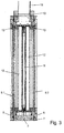
- FIGS. 1 to 7 illustrated embodiments are designed so that the disc 9 is formed as a flat surface. It is of course also possible to form the disc 9 as a tube and to let flow inside the glass tube, the water to be disinfected or the liquid to be disinfected. Such embodiments are in the FIGS. 8, 9 and 11 shown. The operation is similar to the previously illustrated embodiments. Only the geometry and the concentric arrangement around the one glass tube 35 is different.
- FIG. 8 a first embodiment of a tubular device 1 is shown inside this device 1. Inside this device 1, a glass tube 35 is arranged through which the water to be disinfected flows.
- the device 1 is surrounded by outer walls 29.
- an annular chamber 33 which is filled with nitrogen or in which there is a vacuum, arranged as a thermal insulation.
- Concentric with the chamber or chambers 33 is a likewise annular plasma chamber 11 which is filled with a mercury-containing gas or gas mixture arranged.
- the plasma chambers 11 and 12 emit UV light through the glass tube 35 radially inwardly into the water to be disinfected, so that the microbes located there are killed.
- the walls 29 may be reflective to UV rays or a reflective coating may be applied to the outer cylindrical wall of the plasma chambers 11 and 12.
- FIG. 9 an embodiment of plasma chambers 11 and 12 is shown, in which the plasma chambers 11 and 12 have a common wall. It is therefore a structure having substantially three parallel walls 37, 39, and 41st
- At least the walls 37 and 39 are permeable to UV light. If the gas or the gas mixtures located in the plasma chambers 11 and 12 are excited accordingly, UV light is produced in the plasma chamber 11 due to the ionization of the mercury-containing gas having a wavelength of about 254 nm
- the plasma chamber 12 serves as a thermal insulation for the plasma chamber 11. The disc 9, not shown, is thus left of the plasma chamber 12th
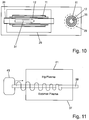
- Such a configuration may be planar, similar to the ones shown in FIGS FIGS. 1 to 7 , or as a cylindrical design, as in FIG. 10 indicated, executed.
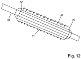
- FIGS. 11 to 13 further alternative possibilities for the coupling of energy are shown.
- FIG. 9 The configuration according to FIG. 9 , in which the plasma chambers 11 and 12 have a common wall 39, is particularly well suited to couple the microwaves via a surface-bound wave in the plasma chambers 11 and 12.
- FIG. 11 such a constellation is shown.
- the dielectric wall 39 is extended slightly beyond the actual chambers 11 and 12, so that a microwave generator 43 can be connected there.
- the electromagnetic radiation radiated by this microwave generator 43 propagates along the wall 39 as a surface-bound wave and thus reaches the plasma chambers 11 and 12. There, the desired excitation of the gases or gas mixtures in the chambers 11 and 12 takes place.
- FIG. 12 a tubular arrangement is indicated, in which the chambers 11 and 12 are excited without electrodeless induction, in particular by inductive coupling.
- the induction coil required for this purpose is designated by the reference numeral 45.
- FIG. 13 a further variant of the plasma chambers 11 and 12 is shown.
- the plasma chamber 11 via heated electrodes 47, 49 which are acted upon, for example, with an alternating voltage of 50 Hz, excited.
- This suggestion is very widespread, works well and is very reliable.
- the electrode 49 has a dual function in this embodiment, since it is also used in connection with the Dielectric Barrier Discharge - excitation of the plasma chamber 12.
- a DBD electrode 41 is arranged parallel to the wall 37.
- a high-frequency voltage having a frequency of several kHz up to, for example, 100 kHz is applied, thereby leading to the desired excimer formation in the plasma chamber 12.
- the DBD electrode is designed, for example, as a grid or network structure, so that the UV light 23 passes through the DBD electrode 51 can be emitted through.
- excitation be it via a magnetron 17, a microwave generator 43, an induction coil 45, as well as electrodes 47, 49 and 51 can of course be used correspondingly in all illustrated embodiments. In this case, the advantages of the invention are achieved in all cases.
Description
Die Erzeugung von UV-Licht und VUV-Licht durch die Anregung von Gasen oder Gasgemischen mit hochfrequenten elektrischen Wellen, insbesondere mit Mikrowellen, ist bspw. aus der
Aus
Aus der
Die aus der
Auch die
Diese herkömmlichen Entladungslampen sind hinlänglich bekannt und haben sich in der Praxis bewährt. Ein besonderer Vorteil solcher lonisationsstrahler mit einem Gas, das Quecksilber oder Verbindungen davon enthält, ist darin zu sehen, dass ein Großteil des emittierten Lichts eine Wellenlänge von etwa 254 nm hat und dieses Licht sehr effektiv, das heißt mit einem guten Wirkungsgrad erzeugt wird.These conventional discharge lamps are well known and have proven themselves in practice. A particular advantage of such ionization radiators with a gas containing mercury or compounds thereof is that much of the emitted light has a wavelength of about 254 nm and this light is generated very effectively, that is with good efficiency.
Dieses Licht mit einer Wellenlänge von 254 nm hat eine desinfizierende Wirkung. Es wird vermutet, dass dieses Licht die DNA der beispielsweise das Abwasser oder Trinkwasser verunreinigenden Mikroben beschädigt oder sogar zerstört. Allerdings wird in der Literatur berichtet, dass sich die derart behandelten Mikroben relativ rasch wieder erholen.This light with a wavelength of 254 nm has a disinfecting effect. It is believed that this light damages or even destroys the DNA of, for example, the sewage or drinking water contaminating microbes. However, it is reported in the literature that the microbes treated in this way recover relatively quickly.
Ein Excimer-Strahler, wie er beispielsweise aus der
Laut der Internet-Enzyklopädie Wikipedia handelt es sich bei einem Excimer (Kurzform von "excited dimer") um ein kurzlebiges Teilchen, das aus zwei oder mehr zusammenhängenden Atomen besteht. Die Besonderheit gegenüber einem Molekül besteht darin, dass das Excimer nur gebildet werden kann, wenn einer der Bindungspartner sich in einem angeregten Zustand befindet. Verliert dieses Teilchen Energie, trennen sich die Bindungspartner und kehren in den Grundzustand zurück. Im Grundzustand haben die vormaligen Bindungspartner eine abstoßende Wirkung auf einander.According to the Internet Encyclopaedia Wikipedia, an excimer (short for "excited dimer") is a short-lived particle that consists of two or more connected atoms. The peculiarity of a molecule is that the excimer can only be formed if one of the binding partners is in an excited state. If this particle loses energy, the binding partners separate and return to their ground state. In the ground state, the former binding partners have a repulsive effect on each other.
Die bei der erfindungsgemäßen Vorrichtung eingesetzten Excimer-Strahler emittieren Licht mit einer Wellenlänge, die spezifisch für das eingefüllte Gas beziehungsweise Gasgemisch ist.The excimer radiators used in the device according to the invention emit light having a wavelength which is specific to the gas or gas mixture introduced.
Der Erfindung liegt die Aufgabe zugrunde, eine Vorrichtung zur Erzeugung von UV-Licht bereitzustellen, die einfach aufgebaut ist und welche eine sehr effektive und wirksame Abtötung von Keimen, zum Beispiel in Abwasser, erlaubt.The invention has for its object to provide a device for generating UV light, which is simple in construction and which allows a very effective and effective killing of germs, for example in wastewater.
Diese Aufgabe wird mit einer Vorrichtung zur Erzeugung von UV-Licht gemäß Anspruchs 1 gelöst.This object is achieved with a device for generating UV light according to
Dies ist dies möglich, wenn die Plasmakammern der zweiten Gruppe zwischen einer Scheibe und den Plasmakammern der ersten Gruppe angeordnet sind.This is possible if the plasma chambers of the second group are arranged between a disk and the plasma chambers of the first group.
Durch die erfindungsgemäße Vorrichtung wird UV- Licht mit unterschiedlichen Wellenlängen emittiert.By the device according to the invention UV light is emitted with different wavelengths.
Das Licht, das aus dem quecksilberhaltigen Gas oder Gasgemisch in der ersten Gruppe von Plasmakammern entsteht, hat eine Wellenlänge von etwa 254 nm und kann mit einem sehr hohen Wirkungsgrad von etwa 40% erzeugt werden. Auch ist die Desinfektionswirkung sehr gut, weil dieses UV-Licht die DNA der Mikroben zumindest angreift, wenn nicht sogar zerstört.The light resulting from the mercury-containing gas or gas mixture in the first group of plasma chambers has a wavelength of about 254 nm and can be generated with a very high efficiency of about 40%. Also, the disinfecting effect is very good because this ultraviolet light attacks the DNA of the microbes at least, if not destroyed.
Das UV-Licht aus der zweiten Gruppe von Plasmakammern hat eine kürzere Wellenlänge als das zuvor beschriebene UV-Licht und ist somit energiereicher. Es wird vermutet, dass daher die organische Masse der mikrobiellen Zelle angegriffen wird. Dies ist eine nachhaltige Schädigung der mikrobiellen Zelle und bewirkt daher auch eine nachhaltige Entkeimung.The UV light from the second group of plasma chambers has a shorter wavelength than the previously described UV light and is thus more energetic. It is believed that therefore the organic mass of the microbial cell is attacked. This is a lasting damage to the microbial cell and therefore also causes a sustainable sterilization.
Durch diesen kombinierten Angriff einerseits auf die DNA der Mikroben und andererseits die Oxidation der organischen Masse der Mikroben wird eine sehr wirkungsvolle und langandauernde Desinfektionswirkung erreicht. Dabei verstärken sich die beiden "Angriffe" wechselseitig, so dass die desinfizierende Wirkung besser ist als wenn nur UV-Strahlung aus einer Lichtquelle eingesetzt wird.By this combined attack on the one hand on the DNA of the microbes and on the other hand, the oxidation of the organic matter of microbes a very effective and long-lasting disinfecting effect is achieved. The two "attacks" reinforce each other, so that the disinfecting effect is better than when only UV radiation from a light source is used.
Weil beide Lampentypen in einer gemeinsamen Vorrichtung zusammengefasst sind, ist der apparative Aufwand zudem niedriger; manche Komponenten können sogar doppelt genutzt werden. Beispielsweise können die Mikrowellen-Generatoren die in beiden Gruppen von Plasmakammern befindliche Gase zu einer elektrischen Entladung anregen. Dies führt insgesamt zu reduzierten Herstellungs- und Betriebskosten und erhöht die Effizienz.Because both lamp types are combined in a common device, the expenditure on equipment is also lower; some components can even be used twice. For example, the microwave generators can excite the gases in both groups of plasma chambers to an electrical discharge. Overall, this leads to reduced manufacturing and operating costs and increases efficiency.
Die Anregung der ersten Gruppe von Plasmakammern kann über Elektroden erfolgen, über eine induktive Kopplung und/oder Mikrowellen. Bei der zweiten Gruppe von Plasmakammern kann die Gasfüllung mit Hilfe einer Dielectric Barrier Discharge (DBC), d.h. einer dielektrisch behinderten Entladung, einer kapazitiven Entladung, einer induktiven Kopplung und/oder Mikrowellen erzeugen.Excitation of the first group of plasma chambers may be via electrodes via an inductive coupling and / or microwaves. In the second group of plasma chambers, gas filling may be accomplished by means of a dielectric barrier discharge (DBC), i. a dielectrically impeded discharge, a capacitive discharge, an inductive coupling and / or microwaves generate.
Grundsätzlich ist es auch möglich, die in der ersten Gruppe und der zweiten Gruppe von Plasmakammern befindlichen Gase oder Gasgemische auf unterschiedliche Arten und Weisen anzuregen, um UV-Licht zu erzeugen. Daher kann den Randbedingungen des Einsatzgebiets entsprechend aus den zuvor genannten Möglichkeiten ausgewählt werden.In principle, it is also possible to excite the gases or gas mixtures in the first group and the second group of plasma chambers in different ways in order to generate UV light. Therefore, the boundary conditions of the application can be selected accordingly from the aforementioned possibilities.
Eine sehr effektive und effiziente Art die Mikrowellen in die Plasmakammern einzukoppeln besteht darin, die Mikrowellen als Oberflächen gebundene Wellen in beispielsweise eine Außenwand oder eine andere Wand der Plasmakammern einzukoppeln (engl.: surface-wave-sustained plasma). Dann verbreitet sich die elektromagnetische Welle entlang der Grenze der Medien mit unterschiedlichen Brechungskoeffizienten. In diesem Fall ist eines der Medien die Wand, das andere das Plasma und das dritte Medium ggf. die Außenluft. Das elektrische Feld der Mikrowellenstrahlung dringt bis zu einer gewissen Tiefe in das Plasmagas ein (sogenannte evaneszente Welle) und regt dort eine elektrische Ladung und in folge dessen eine Plasmabildung an.A very effective and efficient way to couple the microwaves into the plasma chambers is to bond the microwaves as surfaces Wave in, for example, an outer wall or another wall of the plasma chambers (surface-wave-sustained plasma). Then, the electromagnetic wave propagates along the boundary of the media with different refractive indices. In this case one of the media is the wall, the other the plasma and the third medium possibly the outside air. The electric field of the microwave radiation penetrates to a certain depth in the plasma gas (so-called evanescent wave) and there stimulates an electric charge and consequently a plasma formation.
Es ist möglich, das Magnetron zur Erzeugung von Mikrowellen außerhalb oder innerhalb der Kammer anzuordnen. Wenn das Magnetron außerhalb der Kammer angeordnet ist, dann weist die Kammer in der Regel eine Öffnung auf, durch die die Mikrowellen in die Kammer gelangen. Alternativ können die in den Plasmakammern befindlichen Gase auch durch oberflächengebundene Wellen angeregt werden.It is possible to arrange the magnetron for generating microwaves outside or inside the chamber. If the magnetron is located outside the chamber, then the chamber will typically have an opening through which the microwaves will enter the chamber. Alternatively, the gases in the plasma chambers can also be excited by surface-bound waves.
Es ist jedoch auch ohne Weiteres möglich, außerhalb der Kammer Elektroden für eine Dielectric Barrier Discharge (DBD) und/oder einer kapazitiven Entladung oder Spulen zur induktiven Kopplung (ICP) vorzusehen.However, it is also readily possible to provide electrodes for a dielectric barrier discharge (DBD) and / or a capacitive discharge or coils for inductive coupling (ICP) outside the chamber.
Da die Lampeneffizienz der ersten Gruppe von Plasmakammern mit steigender Temperatur zunimmt und das zu desinfizierende Abwasser üblicherweise Temperaturen kleiner 20° C hat, ist in erfindungsgemäßer Weiterbildung vorgesehen, dass zwischen einer Scheibe der Kammer und der ersten Gruppe von Plasmakammern die Wärmedämmung vorgesehen ist. Diese Wärmedämmung kann beispielsweise durch das in der Vorrichtung befindliche Gas erfolgen, wenn die Plasmakammern der ersten Gruppe mit einem gewissen Abstand zu der Scheibe angeordnet sind.Since the lamp efficiency of the first group of plasma chambers increases with increasing temperature and the wastewater to be disinfected usually has temperatures below 20 ° C., provision is made according to the invention for the thermal insulation to be provided between a pane of the chamber and the first group of plasma chambers. This thermal insulation can be done for example by the gas in the device when the plasma chambers of the first group are arranged at a certain distance from the disc.
Zur weiteren Verbesserung der Wärmedämmung kann jedoch auch noch eine für UV-Licht transparente Wärmedämmung in Form einer Kammer, die beispielsweise vakuumiert ist oder mit Stickstoff gefüllt ist, zwischen die Scheibe und den oder die Plasmakammern der ersten Gruppe von angeordnet werden. Diese zusätzliche Kammer dient als für UV-Licht transparente Wärmedämmung.To further improve the thermal insulation, however, it is also possible for a UV-transparent heat insulation in the form of a chamber, which is, for example, vacuum-sealed or filled with nitrogen, to be placed between the two Disc and the or the plasma chambers of the first group are arranged by. This additional chamber serves as transparent to UV light thermal insulation.
Bei der zweiten Gruppe von Plasmakammern, in denen durch Anregung Excimer gebildet werden, ist es erstrebenswert, die Kühlwirkung des zu desinfizierenden Abwassers auszunützen, weil die Effizienz mit zunehmender Temperatur zurückgeht. Daher ist es vorteilhaft, wenn die Plasmakammern der zweiten Gruppe in direktem und gut wärmeleitendem Kontakt zu der Scheibe der erfindungsgemäßen Vorrichtung sind.In the second group of plasma chambers, in which excimer are formed by excitation, it is desirable to take advantage of the cooling effect of the waste water to be disinfected, because the efficiency decreases with increasing temperature. Therefore, it is advantageous if the plasma chambers of the second group are in direct and good heat-conducting contact with the disk of the device according to the invention.
Die erfindungsgemäße Vorrichtung kann als rechteckiges Gebilde mit einer oder zwei ebenen Scheiben ausgeführt sein. Es ist jedoch auch möglich, alle Bauteile in der Art eines Zylinders konzentrisch um eine Mittelachse anzuordnen. Dann ist üblicherweise das Innere dieser kreisringförmigen Anordnung von dem zu desinfizierenden Abwasser durchströmt und die Scheibe ist ein (zylindrisches) Rohr aus Glas, durch welches das zu reinigende Abwasser strömt. Konzentrisch um diese rohrförmige Scheibe herum sind dann die Plasmakammern in Form von ringförmigen Kammern angeordnet.The device according to the invention can be designed as a rectangular structure with one or two flat panes. However, it is also possible to arrange all the components in the manner of a cylinder concentrically about a central axis. Then usually the interior of this annular arrangement is flowed through by the wastewater to be disinfected and the disc is a (cylindrical) tube of glass, through which flows the wastewater to be purified. Concentric around this tubular disk around the plasma chambers are then arranged in the form of annular chambers.
Durch das von der erfindungsgemäßen Vorrichtung emittierte UV-Licht unterschiedlicher Wellenlänge können verschiedenste photochemische und photophysikalische Prozesse so angeregt werden, dass diese Prozesse gleichmäßig und mit hoher Reaktionsgeschwindigkeit ablaufen. Beispielsweise ist die Desinfektion von Trink- und Abwässern, Abgasen und von festen Stoffen, wie bspw. Lebensmitteln besonders wirksam, weil die Bakterien mit zwei verschiedenen Wirkmechanismen angegriffen werden.By the UV light of different wavelengths emitted by the device according to the invention, a wide variety of photochemical and photophysical processes can be excited in such a way that these processes proceed uniformly and at high reaction rates. For example, the disinfection of drinking and waste water, exhaust gases and solid substances, such as food is particularly effective because the bacteria are attacked with two different mechanisms of action.
Weitere vorteilhafte Ausgestaltungen der Erfindung sind den Unteransprüchen entnehmbar. Im Übrigen wird bezüglich der konstruktiven Ausgestaltung der Vorrichtung auf die
Die erfindungsgemäße Vorrichtung kann auch in einen Kanal eingebaut werden, sodass das durch den Kanal strömende Medium, wie beispielsweise Trink- oder Abwasser, mit UV-Licht bestrahlt und dadurch desinfiziert werden kann.The device according to the invention can also be installed in a channel, so that the medium flowing through the channel, such as drinking or waste water, can be irradiated with UV light and thereby disinfected.
Weitere Vorteile und vorteilhafte Ausgestaltungen der Erfindung sind der nachfolgenden Zeichnung, deren Beschreibung und den Patentansprüchen entnehmbar.Further advantages and advantageous embodiments of the invention are the following drawings, the description and the claims removable.
-
Figur 1 : eine isometrische Darstellung einer erfindungsgemäßen Kammer teilweise geschnitten;FIG. 1 : an isometric view of a chamber according to the invention partially cut; -
Figur 2 : eine isometrische Darstellung eine erfindungsgemäßen Kammer;FIG. 2 : an isometric view of a chamber according to the invention; -
Figur 3 : einen Querschnitt durch eine erfindungsgemäße Kammer;FIG. 3 a cross section through a chamber according to the invention; -
Figur 4 : eine isometrische Darstellung einer erfindungsgemäßen Vorrichtung mit Kammer, Wellenleiter und mehreren Magnetrons.FIG. 4 : An isometric view of a device according to the invention with chamber, waveguide and several magnetrons. -
Figur 5 : ein Querschnitt durch eine Einbausituation undFIG. 5 : a cross section through a mounting situation and -
Figuren 6 bis 12 : verschiedene Ausführungsbeispiele erfindungsgemäßer Vorrichtungen.FIGS. 6 to 12 : Various embodiments of devices according to the invention.
In
Die Vorrichtung 1 besteht aus einem umlaufenden Rahmen 3. An einer Vorderseite des Rahmens 3 ist eine Blende 5 angeschraubt. Die Schraubenlöcher dieser Schraubverbindung sind mit dem Bezugszeichen 7 versehen. Die Blende 5 dient zur Aufnahme einer Scheibe 9. Diese Scheibe 9 ist aus einem Material hergestellt, welches durchlässig für UV-Licht und/oder VUV-Licht ist. Auf der Scheibe 9 kann ein Gitter (nicht dargestellt) aufgebracht werden, welches undurchlässig für Mikrowellenstrahlung ist, jedoch UV-Licht passieren lässt. Durch das Zurückhalten der Mikrowellen werden die Effizienz erhöht und ein geschlossener Käfig nach Farraday gebildet.The
Im Inneren der Vorrichtung 1 sind eine Reihe von Plasmakammern 11 und zwei Reihen von Plasmakammern 12 angeordnet. Die Plasmakammern 11 bilden eine erste Gruppe und die Plasmakammern 12 bilden eine zweite Gruppe.Inside the
Die Plasmakammern 11 sind mit einem deutlichen Abstand zu den Scheiben 9.1 bzw. 9.2 angeordnet.The
Dadurch wird eine Wärmeübertragung von den Scheiben 9, auf die erste Gruppe von Plasmakammern 11 deutlich reduziert oder sogar vollständig unterbunden.As a result, a heat transfer from the
Dies ist deshalb vorteilhaft, weil die Plasmakammern 11 der ersten Gruppe mit einem quecksilberhaltigen Gas oder Gasgemisch gefüllt sind, welches mit zunehmender Betriebstemperatur mehr UV-Licht emittiert. Daher ist eine Kühlung dieser ersten Gruppe von Plasmakammern 11 durch das zu desinfizierende Trinkwasser oder Abwasser, welches an den Scheiben 9 vorbeiströmt, unerwünscht. Im Übrigen stellen die Plasmakammern 12 der zweiten Gruppe auch eine Wärmedämmung zwischen den Plasmakammern 11 und den Scheiben 9.1 bzw. 9.2 dar.This is advantageous because the
Auf der Rückseite des Rahmens 3 sind ebenfalls eine Blende 5 und eine Scheibe 9 vorhanden. Der Aufbau entspricht der Vorderseite, so dass auf eine detaillierte Beschreibung verzichtet werden kann.On the back of the
In
Durch die Öffnung 10 an der Oberseite der Kammer 1 gelangen Mikrowellenstrahlungen in das Innere der Kammer 1. Dort regen die Mikrowellen das in den Plasmakammern 11 und 12 befindliche Gas oder Gasgemisch zur Emission von UV-Licht und/oder VUV-Licht an. Durch die Wahl des Gases und des im Inneren der Plasmakammern 11 herrschenden Drucks, kann die Wellenlänge des von den Plasmakammern 11 emittierten Lichts in weiten Bereichen eingestellt werden. In den Plasmakammern 11 und 12 der ersten Gruppe und der der zweiten Gruppe findet jeweils eine Anregung der Gase beziehungsweise Gasgemische statt. Beides führt zur Emission von UV-Licht, allerdings bei unterschiedlichen Wellenlängen.Through the
In
Bei Bedarf kann eine Dichtung - beispielsweise aus Silikon - zwischen Scheibe 9, Blende 5 sowie Blende 5 und Rahmen 3 vorgesehen werden. Auf die Öffnung 10 in dem Rahmen 3 ist ein Wellenleiter 15 aufgesetzt.If necessary, a seal - for example made of silicone - between
Der Wellenleiter 15 dient dazu, die von einem oder mehreren Magnetrons 17 emittierten Mikrowellen durch die Öffnung 10 ins Innere der Kammer 1 zu leiten. Bei vielen Anwendungsfällen der erfindungsgemäßen Vorrichtung können das oder die Magnetrons 17 direkt auf den Rahmen 3 aufgesetzt werden. Der Wellenleiter 15 ist dann entbehrlich.The
In
Durch den Einsatz eines oder mehrerer von Magnetrons 17 wird über die gesamte Länge der Kammer 1 Mikrowellen in die Kammer 1 eingekoppelt werden, so dass alle Plasmakammern 11 und 12 mit etwa der gleichen Intensität von den Mikrowellen angeregt werden. Weitere Vorteile der Verwendung mehrer Magnetrons 17 sind die Verwendbarkeit kostengünstiger Standard-Magnetrons und die Betriebssicherheit wegen der mehrfachen Redundanz.Through the use of one or more of
Durch die Reflexion der Mikrowellen im Inneren der Vorrichtung 1 werden die Plasmakammern 11 und 12 nahezu mit gleicher Intensität zum Leuchten beziehungsweise zum Emittieren von UV-Licht angeregt werden. Daher kann auch auf Reflektoren oder sonstige Einrichtungen zur Lenkung der Mikrowellen innerhalb der Kammer 1 verzichtet werden. Es ist auf jeden Fall vorteilhaft, wenn die Innenwände der Kammer 1 aus einem Material bestehen und/oder ein Gitter aufweisen, welches Mikrowellen reflektiert oder mit einer entsprechenden Mikrowellen reflektierenden Beschichtung versehen sind.Due to the reflection of the microwaves in the interior of the
In
Der Kanal ist in
Die Vorrichtung 1 ist so in dem Kanal 19 angeordnet, dass die Längsrichtung der Vorrichtung 1 parallel zur Strömungsrichtung des Wassers im Kanal 19 verläuft. In dem Querschnitt gemäß
Dieses emittierte UV-Licht ist in
An den Seitenwänden des Kanals 19 kann eine UV-Licht reflektierende Beschichtung 25 vorgesehen sein. Dadurch wird gewährleistet, dass UV-Licht, welches an die Seitenwände des Kanals 19 gelangt ist, nicht von den Seitenwänden absorbiert wird, sondern von der Beschichtung 25 reflektiert wird und erneut zur Desinfektion des Wassers dienen kann. Dadurch wird auf einfache Weise der Wirkungsgrad der erfindungsgemäßen Vorrichtung verbessert.On the side walls of the
Um sicherzustellen, dass das gesamte durch den Kanal 19 strömende Wasser desinfiziert wird, sind in dem Kanal 19 Leitkörper 27 vorgesehen. Diese Leitkörper 27 verengen im Bereich der Lichtquelle 1 den freien Strömungsquerschnitt auf ein Maß, das auf die Abmessungen der Scheibe 9 abgestimmt ist.In order to ensure that all the water flowing through the
In Folge dessen strömt das gesamte in dem Kanal 19 befindliche Wasser an der Scheibe 9 vorbei und gerät dabei in den durch die Pfeile 23 angedeuteten Strahlungsbereich der erfindungsgemäßen UV-Lichtquelle.As a result, the entire water in the
In der
Bei dieser Ausführung ist nur eine Scheibe 9 vorhanden. Die anderen Seiten und Wände 29 der Vorrichtung 1 bestehen aus einem für UV-Licht undurchlässigen Material, wie beispielsweise Edelstahl. An dieser Darstellung ist sehr gut zu sehen, dass die erste Gruppe von Plasmakammern 11 beabstandet zur Scheibe 9 angeordnet ist, so dass keine Wärmeleitung zwischen der Glasscheibe 9 und der Plasmakammern 11 stattfindet. Das Innere der Vorrichtung 1 ist mit Stickstoff N2 gefüllt. Dieses Inertgas hat gute Wärmedämmeigenschaften, so dass der zwischen Scheibe 9 und Plasmakammern 11 befindliche Stickstoff N2 die Wärmedämmung weiter verbessert.In this embodiment, only one
Die zweite Gruppe von Plasmakammern 12, in denen durch die Anregung des darin befindlichen Gases oder Gasgemisches Excimer gebildet werden, sind dagegen in direktem Kontakt mit der Scheibe 9 angeordnet, so dass die Scheibe 9 bzw. das dahinter an der Scheibe 9 vorbeiströmende Wasser (nicht dargestellt) zunächst die Scheibe 9 und dadurch mittelbar auch die Plasmakammern 12 kühlt. Dadurch wird die Effizienz der UV-Lichterzeugung in den Plasmakammern 12 erhöht.The second group of
Die Fließrichtung des zu desinfizierenden Wassers (nicht dargestellt) ist durch Pfeile 31 angedeutet. Bei dieser seriellen Anordnung von Plasmakammern 11, in denen eine Ionisation stattfindet, und Plasmakammern 12, bei denen eine Bildung von Excimern stattfindet, werden die Mikroben in dem Wasser im Wechsel nacheinander mit UV-Licht unterschiedlicher Wellenlänge beaufschlagt, so dass sie wirksam und nachhaltig abgetötet werden und somit das Wasser desinfiziert wird.The direction of flow of the water to be disinfected (not shown) is indicated by
In dem Ausführungsbeispiel gemäß
Die in den
In der
Die Vorrichtung 1 ist von Außenwänden 29 umgeben. Im Innenraum der Vorrichtung 1 ist eine ringförmige Kammer 33, die mit Stickstoff gefüllt ist oder in der ein Vakuum herrscht, als Wärmedämmung angeordnet. Konzentrisch zu der oder den Kammern 33 ist eine ebenfalls ringförmig ausgebildete Plasmakammer 11, die mit einem quecksilberhaltigen Gas oder Gasgemisch gefüllt ist, angeordnet.The
Stromabwärts der Plasmakammer 11 ist eine weitere ringförmige Plasmakammer 12 angeordnet, in der sich ein Gas befindet, das Excimer bildet, wenn es entsprechend angeregt wird. Dies bedeutet, dass die Plasmakammern 11 und 12 UV-Licht durch das Glasrohr 35 hindurch radial nach innen in das zu desinfizierende Wasser emittieren, so dass die dort befindlichen Mikroben abgetötet werden. Um den Wirkungsgrad der Vorrichtung 1 zu erhöhen, können entweder die Wände 29 reflektierend für UV-Strahlen ausgebildet sein oder es wird an der zylindrischen Außenwand der Plasmakammern 11 und 12 eine reflektierende Beschichtung angebracht.Downstream of the
In der
Zumindest die Wände 37 und 39 sind durchlässig für UV-Licht. Wenn nun das in den Plasmakammern 11 und 12 befindliche Gas bzw. die dort befindlichen Gasgemische entsprechend angeregt werden, dann entsteht in der Plasmakammer 11 UV-Licht aufgrund der Ionisation des quecksilberhaltigen Gases mit einer Wellenlänge von etwa 254 nm. In der Plasmakammer 12 entsteht aufgrund der Excimerbildung ein kurzwelligeres UV-Licht mit einer Wellenlänge von etwa 200 nm. Die Plasmakammer 12 dient hierbei gleichzeitig als Wärmedämmung für die Plasmakammer 11. Die nicht dargestellte Scheibe 9 befindet sich also links der Plasmakammer 12.At least the
Eine solche Konfiguration kann planar, ähnlich wie in den
In den
Die Konfiguration gemäß
In der
In der
Die Elektrode 49 hat bei diesem Ausführungsbeispiel eine Doppelfunktion, da sie auch noch im Zusammenhang mit der Dielectric Barrier Discharge - Anregung der Plasmakammer 12 benutzt wird. Parallel zu der Wand 37 ist eine DBD-Elektrode 41 angeordnet. Zwischen der Elektrode 49 und der DBD-Elektrode 51 wird eine hochfrequente Spannung mit einer Frequenz von mehreren kHz bis hin zu beispielsweise 100 kHz angelegt und führt dadurch zu der gewünschten Excimerbildung in der Plasmakammer 12.The
Damit das UV-Licht 23 durch die Wand 37 und die DBD-Elektrode hindurch in das zu desinfizierende Abwasser gelangen kann, ist die DBD-Elektrode beispielsweise als Gitter- oder Netzstruktur ausgebildet, so dass das UV-Licht 23 durch die DBD-Elektrode 51 hindurch emittiert werden kann. Diese Arten der Anregung, sei es über ein Magnetron 17, einen Mikrowellengenerator 43, eine Induktionsspule 45, sowie Elektroden 47, 49 und 51 können selbstverständlich bei allen dargestellten Ausführungsformen entsprechend eingesetzt werden. Dabei werden in allen Fällen die erfindungsgemäßen Vorteile erreicht.In order for the
Claims (13)
- Device for producing UV light and/or vacuum-UV-light, comprising a chamber (1), comprising several gas-filled plasma chambers (11, 12), wherein a first group of plasma chambers (11) is filled with a mercury-containing ionizable gas, and a second group of plasma chambers (12) is filled with halogens or noble gases or mixtures or chemical compounds of these gases that form excimers upon suitable excitation and wherein the chamber (1) comprises at least one plate (9, 9.1, 9.2) that is transparent for UV light and/or vacuum-UV-light, characterized in that between the plasma chambers (11) of the first group and the plate (9, 9.1, 9.2) a thermal insulation that is transparent for UV light and/or VUV light is arranged, wherein a plasma chamber (12) of the second group serves as that thermal insulation for a plasma chamber (11) of the first group.
- Device according to claim 1, characterized in that the first group of plasma chambers (11) emits UV light at a wavelength of 254 nm and in that the second group of plasma chambers (12) emits UV light at a wavelength of less than 250 nm, preferably of less than 220 nm.
- Device according to claim 1 or 2, characterized in that the first group of plasma chambers (11) is excited by electrodes, wherein the frequency of excitation comprises a range between approximately 50 Hz up to 105 kHz, by means of inductive coupling (ICP), and/or microwaves.
- Device according to one of the preceding claims, characterized in that the second group of plasma chambers (12) is excited with a dielectric barrier discharge (DBC), a capacitive discharge, inductive coupling (ICP), and/or microwaves.
- Device according to one of the claims 3 or 4, characterized in that the microwaves are injected as surface-sustained wave into the plasma chambers (11, 12) .
- Device according to one of the preceding claims, characterized in that it comprises at least one magnetron (17) for generating microwaves and in that the at least one magnetron (17) is arranged outside or inside of the chamber (1).
- Device according to one of the preceding claims, characterized in that the chamber (1) comprises at least one opening (10) through which the microwaves can pass into the chamber (1).
- Device according to one of the claims 3 to 7, characterized in that outside of the chamber (1) electrodes for inductive coupling (ICP), a dielectric barrier discharge (DBC) and/or a capacitive discharge are provided.
- Device according to one of the preceding claims, characterized in that a first row of plasma chambers of the first group (11) is arranged parallel to a first plate (9.1).
- Device according to one of the preceding claims, characterized in that a second row of plasma chambers of the first group (11) is arranged parallel to a second plate (9.2).
- Device according to claim 6, characterized in that in the chamber (1) at least one opening (10) is provided and in that through the at least one opening (10) the microwaves generated by the at least one magnetron (17) are injected into the chamber (1).
- Device according to one of the preceding claims, characterized in that the plasma chambers (11) of the first group are filled with mercury vapor and noble gases.
- Device according to one of the preceding claims, characterized in that in the plasma chambers (11, 12) a pressure between 10-2 mbar and 10 bar exists.
Applications Claiming Priority (2)
| Application Number | Priority Date | Filing Date | Title |
|---|---|---|---|
| DE102012219064.3A DE102012219064A1 (en) | 2012-10-19 | 2012-10-19 | UV light source with combined ionization and formation of excimers |
| PCT/EP2013/071880 WO2014060592A1 (en) | 2012-10-19 | 2013-10-18 | Uv light source having combined ionization and formation of excimers |
Publications (2)
| Publication Number | Publication Date |
|---|---|
| EP2909856A1 EP2909856A1 (en) | 2015-08-26 |
| EP2909856B1 true EP2909856B1 (en) | 2018-02-21 |
Family
ID=49515327
Family Applications (1)
| Application Number | Title | Priority Date | Filing Date |
|---|---|---|---|
| EP13785385.9A Active EP2909856B1 (en) | 2012-10-19 | 2013-10-18 | Uv light source having combined ionization and formation of excimers |
Country Status (4)
| Country | Link |
|---|---|
| US (1) | US9718705B2 (en) |
| EP (1) | EP2909856B1 (en) |
| DE (1) | DE102012219064A1 (en) |
| WO (1) | WO2014060592A1 (en) |
Families Citing this family (3)
| Publication number | Priority date | Publication date | Assignee | Title |
|---|---|---|---|---|
| DE102014207688A1 (en) * | 2014-04-24 | 2015-10-29 | Fraunhofer-Gesellschaft zur Förderung der angewandten Forschung e.V. | Apparatus for the photochemical treatment of contaminated water |
| CZ2015815A3 (en) | 2015-11-16 | 2017-03-15 | Univerzita Tomáše Bati ve Zlíně | A device for generating UV radiation and the method of generating this radiation |
| KR101863166B1 (en) * | 2016-06-22 | 2018-06-01 | 한국에너지기술연구원 | Uv led photocatalysis water purifying device |
Family Cites Families (23)
| Publication number | Priority date | Publication date | Assignee | Title |
|---|---|---|---|---|
| DE102006C (en) | ||||
| US4255663A (en) * | 1977-03-24 | 1981-03-10 | Lewis James H | Disposable liquid sterilizer unit |
| DE3320597C2 (en) * | 1983-06-08 | 1986-11-27 | W.C. Heraeus Gmbh, 6450 Hanau | High pressure gas discharge lamp |
| CH677292A5 (en) | 1989-02-27 | 1991-04-30 | Asea Brown Boveri | |
| CH680099A5 (en) | 1990-05-22 | 1992-06-15 | Asea Brown Boveri | |
| DE4430300C1 (en) * | 1994-08-26 | 1995-12-21 | Abb Research Ltd | Excimer emitters and their use |
| GB9522686D0 (en) * | 1995-11-06 | 1996-01-10 | Jenton R A & Co Ltd | Ultraviolet bulb |
| JP2002537767A (en) * | 1999-02-15 | 2002-11-12 | フラウンホファー ゲセルシャフトツール フェールデルンク ダー アンゲヴァンテン フォルシュンク エー.ファオ. | Method and probe carrier system for splitting and concentrating substances in situ |
| US6193894B1 (en) * | 1999-06-23 | 2001-02-27 | Brad C. Hollander | Methods and apparatus for disinfecting and sterilizing water in water dispensers using ultraviolet radiation |
| JP3591393B2 (en) * | 1999-11-02 | 2004-11-17 | ウシオ電機株式会社 | Dielectric barrier discharge lamp device |
| GB0206673D0 (en) * | 2002-03-21 | 2002-05-01 | Jenact Ltd | Elongate ultraviolet light source |
| GB2413005B (en) * | 2004-04-07 | 2007-04-04 | Jenact Ltd | UV light source |
| JP2006040867A (en) * | 2004-06-23 | 2006-02-09 | Hoya Candeo Optronics株式会社 | Excimer lamp apparatus |
| DE102004057155B4 (en) * | 2004-11-26 | 2007-02-01 | Fraunhofer-Gesellschaft zur Förderung der angewandten Forschung e.V. | Process for the chemical functionalization of surfaces by plasma polymerization |
| WO2006114988A1 (en) * | 2005-04-22 | 2006-11-02 | Hoya Candeo Optronics Corporation | Excimer lamp |
| DE102006022970B3 (en) * | 2006-05-11 | 2007-11-22 | Fraunhofer-Gesellschaft zur Förderung der angewandten Forschung e.V. | UV-light source |
| GB2451873B (en) * | 2007-08-15 | 2009-08-12 | Jenact Ltd | UV irradiator |
| JP5271762B2 (en) * | 2009-03-13 | 2013-08-21 | 株式会社オーク製作所 | Discharge lamp |
| DE102009025667A1 (en) * | 2009-06-17 | 2010-12-23 | Heraeus Noblelight Gmbh | lamp unit |
| US8378323B1 (en) * | 2009-09-16 | 2013-02-19 | Robert L. Spann | Sterilizing toybox apparatus |
| US9168320B1 (en) * | 2010-01-08 | 2015-10-27 | Imaging Systems Technology, Inc. | Ultraviolet plasma-shells |
| US8269190B2 (en) * | 2010-09-10 | 2012-09-18 | Severn Trent Water Purification, Inc. | Method and system for achieving optimal UV water disinfection |
| US8357330B1 (en) * | 2011-08-22 | 2013-01-22 | Kelly Erdlen | Anti-microbial catheter system |
-
2012
- 2012-10-19 DE DE102012219064.3A patent/DE102012219064A1/en not_active Ceased
-
2013
- 2013-10-18 WO PCT/EP2013/071880 patent/WO2014060592A1/en active Application Filing
- 2013-10-18 EP EP13785385.9A patent/EP2909856B1/en active Active
- 2013-10-18 US US14/436,884 patent/US9718705B2/en active Active
Also Published As
| Publication number | Publication date |
|---|---|
| DE102012219064A8 (en) | 2014-07-31 |
| DE102012219064A1 (en) | 2014-04-24 |
| US20150274548A1 (en) | 2015-10-01 |
| EP2909856A1 (en) | 2015-08-26 |
| US9718705B2 (en) | 2017-08-01 |
| WO2014060592A1 (en) | 2014-04-24 |
Similar Documents
| Publication | Publication Date | Title |
|---|---|---|
| EP1048620B1 (en) | Device for the disinfection of water using a UV-C-gas discharge lamp | |
| EP0371304B1 (en) | High-power radiation device | |
| DE60310947T2 (en) | DEVICE FOR GENERATING RADIATION | |
| EP2909856B1 (en) | Uv light source having combined ionization and formation of excimers | |
| EP0482230B1 (en) | High power radiation device | |
| DE102010042670B4 (en) | Device for UV irradiation | |
| DE102005003041A1 (en) | Flash lamp with high radiation density | |
| DE60220086T2 (en) | METHOD AND APPARATUS FOR GENERATING VISIBLE LIGHT IN THE UV AND IR RANGE WITH AN ELECTRODELESS LAMP | |
| DE4302465C1 (en) | Appts. for producing dielectrically-hindered discharge - comprises gas-filled discharge space between two ignition voltage-admitted electrodes | |
| EP2297772A1 (en) | Dielectric barrier discharge lamp configured as a coaxial double tube having a getter | |
| DE102006022970B3 (en) | UV-light source | |
| WO2007128494A1 (en) | Device for treating fluids, especially water sterilization, comprising an electrode-less gas discharge lamp | |
| EP0592794B1 (en) | Apparatus for generating and emitting electromagnetic radiation | |
| EP3134350B1 (en) | Device for the photochemical treatment or cleaning of a liquid medium | |
| WO2015162264A1 (en) | Device for the photochemical treatment of polluted water | |
| DE4100462C2 (en) | ||
| EP2416346B1 (en) | Mercury vapour lamp for homogeneous lighting of an area | |
| WO2017008987A1 (en) | Method for operating a xenon excimer lamp and lamp system comprising an excimer lamp | |
| Varakin | Multiple photon excitation of adsorbed toluene by KrF laser | |
| Tarasenko et al. | Barrier-discharge excilamps: history, operating principle, prospects∗∗ To the radiant memory of Galina Arkad’evna Volkova (1935–2011). | |
| Ahlawat et al. | A dielectric barrier discharge based low pressure narrow band far UV-C 222 nm excimer lamp and its efficiency analysis | |
| DE10242049A1 (en) | Low pressure discharge lamp comprises a gas discharge vessel containing a noble gas filling as buffer gas, electrodes and devices for producing and maintaining a low pressure gas discharge, and a zinc halide | |
| DE102011106498B4 (en) | Irradiation module for microphotoreactors | |
| DE102009030310A1 (en) | Dielectric barrier discharge lamp with discharge spaces | |
| EP2618362B1 (en) | Light emitter and method for its operation |
Legal Events
| Date | Code | Title | Description |
|---|---|---|---|
| PUAI | Public reference made under article 153(3) epc to a published international application that has entered the european phase |
Free format text: ORIGINAL CODE: 0009012 |
|
| 17P | Request for examination filed |
Effective date: 20150226 |
|
| AK | Designated contracting states |
Kind code of ref document: A1 Designated state(s): AL AT BE BG CH CY CZ DE DK EE ES FI FR GB GR HR HU IE IS IT LI LT LU LV MC MK MT NL NO PL PT RO RS SE SI SK SM TR |
|
| AX | Request for extension of the european patent |
Extension state: BA ME |
|
| DAX | Request for extension of the european patent (deleted) | ||
| 17Q | First examination report despatched |
Effective date: 20160608 |
|
| RIC1 | Information provided on ipc code assigned before grant |
Ipc: H01J 61/16 20060101ALN20170428BHEP Ipc: H01J 61/20 20060101ALN20170428BHEP Ipc: C02F 1/32 20060101ALI20170428BHEP Ipc: H01J 61/94 20060101AFI20170428BHEP Ipc: H01J 65/04 20060101ALI20170428BHEP |
|
| GRAP | Despatch of communication of intention to grant a patent |
Free format text: ORIGINAL CODE: EPIDOSNIGR1 |
|
| RAP1 | Party data changed (applicant data changed or rights of an application transferred) |
Owner name: SICO TECHNOLOGY GMBH Owner name: FRAUNHOFER-GESELLSCHAFT ZUR FOERDERUNG DER ANGEWAN |
|
| INTG | Intention to grant announced |
Effective date: 20170914 |
|
| GRAS | Grant fee paid |
Free format text: ORIGINAL CODE: EPIDOSNIGR3 |
|
| GRAA | (expected) grant |
Free format text: ORIGINAL CODE: 0009210 |
|
| AK | Designated contracting states |
Kind code of ref document: B1 Designated state(s): AL AT BE BG CH CY CZ DE DK EE ES FI FR GB GR HR HU IE IS IT LI LT LU LV MC MK MT NL NO PL PT RO RS SE SI SK SM TR |
|
| REG | Reference to a national code |
Ref country code: GB Ref legal event code: FG4D Free format text: NOT ENGLISH |
|
| REG | Reference to a national code |
Ref country code: CH Ref legal event code: EP |
|
| REG | Reference to a national code |
Ref country code: AT Ref legal event code: REF Ref document number: 972572 Country of ref document: AT Kind code of ref document: T Effective date: 20180315 |
|
| REG | Reference to a national code |
Ref country code: IE Ref legal event code: FG4D Free format text: LANGUAGE OF EP DOCUMENT: GERMAN |
|
| REG | Reference to a national code |
Ref country code: DE Ref legal event code: R096 Ref document number: 502013009494 Country of ref document: DE |
|
| REG | Reference to a national code |
Ref country code: NL Ref legal event code: MP Effective date: 20180221 |
|
| REG | Reference to a national code |
Ref country code: LT Ref legal event code: MG4D |
|
| PG25 | Lapsed in a contracting state [announced via postgrant information from national office to epo] |
Ref country code: ES Free format text: LAPSE BECAUSE OF FAILURE TO SUBMIT A TRANSLATION OF THE DESCRIPTION OR TO PAY THE FEE WITHIN THE PRESCRIBED TIME-LIMIT Effective date: 20180221 Ref country code: NL Free format text: LAPSE BECAUSE OF FAILURE TO SUBMIT A TRANSLATION OF THE DESCRIPTION OR TO PAY THE FEE WITHIN THE PRESCRIBED TIME-LIMIT Effective date: 20180221 Ref country code: CY Free format text: LAPSE BECAUSE OF FAILURE TO SUBMIT A TRANSLATION OF THE DESCRIPTION OR TO PAY THE FEE WITHIN THE PRESCRIBED TIME-LIMIT Effective date: 20180221 Ref country code: FI Free format text: LAPSE BECAUSE OF FAILURE TO SUBMIT A TRANSLATION OF THE DESCRIPTION OR TO PAY THE FEE WITHIN THE PRESCRIBED TIME-LIMIT Effective date: 20180221 Ref country code: NO Free format text: LAPSE BECAUSE OF FAILURE TO SUBMIT A TRANSLATION OF THE DESCRIPTION OR TO PAY THE FEE WITHIN THE PRESCRIBED TIME-LIMIT Effective date: 20180521 Ref country code: LT Free format text: LAPSE BECAUSE OF FAILURE TO SUBMIT A TRANSLATION OF THE DESCRIPTION OR TO PAY THE FEE WITHIN THE PRESCRIBED TIME-LIMIT Effective date: 20180221 Ref country code: HR Free format text: LAPSE BECAUSE OF FAILURE TO SUBMIT A TRANSLATION OF THE DESCRIPTION OR TO PAY THE FEE WITHIN THE PRESCRIBED TIME-LIMIT Effective date: 20180221 |
|
| PG25 | Lapsed in a contracting state [announced via postgrant information from national office to epo] |
Ref country code: BG Free format text: LAPSE BECAUSE OF FAILURE TO SUBMIT A TRANSLATION OF THE DESCRIPTION OR TO PAY THE FEE WITHIN THE PRESCRIBED TIME-LIMIT Effective date: 20180521 Ref country code: RS Free format text: LAPSE BECAUSE OF FAILURE TO SUBMIT A TRANSLATION OF THE DESCRIPTION OR TO PAY THE FEE WITHIN THE PRESCRIBED TIME-LIMIT Effective date: 20180221 Ref country code: LV Free format text: LAPSE BECAUSE OF FAILURE TO SUBMIT A TRANSLATION OF THE DESCRIPTION OR TO PAY THE FEE WITHIN THE PRESCRIBED TIME-LIMIT Effective date: 20180221 Ref country code: SE Free format text: LAPSE BECAUSE OF FAILURE TO SUBMIT A TRANSLATION OF THE DESCRIPTION OR TO PAY THE FEE WITHIN THE PRESCRIBED TIME-LIMIT Effective date: 20180221 Ref country code: GR Free format text: LAPSE BECAUSE OF FAILURE TO SUBMIT A TRANSLATION OF THE DESCRIPTION OR TO PAY THE FEE WITHIN THE PRESCRIBED TIME-LIMIT Effective date: 20180522 |
|
| PG25 | Lapsed in a contracting state [announced via postgrant information from national office to epo] |
Ref country code: MT Free format text: LAPSE BECAUSE OF FAILURE TO SUBMIT A TRANSLATION OF THE DESCRIPTION OR TO PAY THE FEE WITHIN THE PRESCRIBED TIME-LIMIT Effective date: 20180221 |
|
| PG25 | Lapsed in a contracting state [announced via postgrant information from national office to epo] |
Ref country code: RO Free format text: LAPSE BECAUSE OF FAILURE TO SUBMIT A TRANSLATION OF THE DESCRIPTION OR TO PAY THE FEE WITHIN THE PRESCRIBED TIME-LIMIT Effective date: 20180221 Ref country code: IT Free format text: LAPSE BECAUSE OF FAILURE TO SUBMIT A TRANSLATION OF THE DESCRIPTION OR TO PAY THE FEE WITHIN THE PRESCRIBED TIME-LIMIT Effective date: 20180221 Ref country code: PL Free format text: LAPSE BECAUSE OF FAILURE TO SUBMIT A TRANSLATION OF THE DESCRIPTION OR TO PAY THE FEE WITHIN THE PRESCRIBED TIME-LIMIT Effective date: 20180221 Ref country code: EE Free format text: LAPSE BECAUSE OF FAILURE TO SUBMIT A TRANSLATION OF THE DESCRIPTION OR TO PAY THE FEE WITHIN THE PRESCRIBED TIME-LIMIT Effective date: 20180221 Ref country code: AL Free format text: LAPSE BECAUSE OF FAILURE TO SUBMIT A TRANSLATION OF THE DESCRIPTION OR TO PAY THE FEE WITHIN THE PRESCRIBED TIME-LIMIT Effective date: 20180221 |
|
| REG | Reference to a national code |
Ref country code: DE Ref legal event code: R097 Ref document number: 502013009494 Country of ref document: DE |
|
| PG25 | Lapsed in a contracting state [announced via postgrant information from national office to epo] |
Ref country code: DK Free format text: LAPSE BECAUSE OF FAILURE TO SUBMIT A TRANSLATION OF THE DESCRIPTION OR TO PAY THE FEE WITHIN THE PRESCRIBED TIME-LIMIT Effective date: 20180221 Ref country code: SM Free format text: LAPSE BECAUSE OF FAILURE TO SUBMIT A TRANSLATION OF THE DESCRIPTION OR TO PAY THE FEE WITHIN THE PRESCRIBED TIME-LIMIT Effective date: 20180221 Ref country code: CZ Free format text: LAPSE BECAUSE OF FAILURE TO SUBMIT A TRANSLATION OF THE DESCRIPTION OR TO PAY THE FEE WITHIN THE PRESCRIBED TIME-LIMIT Effective date: 20180221 Ref country code: SK Free format text: LAPSE BECAUSE OF FAILURE TO SUBMIT A TRANSLATION OF THE DESCRIPTION OR TO PAY THE FEE WITHIN THE PRESCRIBED TIME-LIMIT Effective date: 20180221 |
|
| PLBE | No opposition filed within time limit |
Free format text: ORIGINAL CODE: 0009261 |
|
| STAA | Information on the status of an ep patent application or granted ep patent |
Free format text: STATUS: NO OPPOSITION FILED WITHIN TIME LIMIT |
|
| 26N | No opposition filed |
Effective date: 20181122 |
|
| PG25 | Lapsed in a contracting state [announced via postgrant information from national office to epo] |
Ref country code: SI Free format text: LAPSE BECAUSE OF FAILURE TO SUBMIT A TRANSLATION OF THE DESCRIPTION OR TO PAY THE FEE WITHIN THE PRESCRIBED TIME-LIMIT Effective date: 20180221 |
|
| REG | Reference to a national code |
Ref country code: CH Ref legal event code: PL |
|
| GBPC | Gb: european patent ceased through non-payment of renewal fee |
Effective date: 20181018 |
|
| REG | Reference to a national code |
Ref country code: BE Ref legal event code: MM Effective date: 20181031 |
|
| PG25 | Lapsed in a contracting state [announced via postgrant information from national office to epo] |
Ref country code: MC Free format text: LAPSE BECAUSE OF FAILURE TO SUBMIT A TRANSLATION OF THE DESCRIPTION OR TO PAY THE FEE WITHIN THE PRESCRIBED TIME-LIMIT Effective date: 20180221 Ref country code: LU Free format text: LAPSE BECAUSE OF NON-PAYMENT OF DUE FEES Effective date: 20181018 |
|
| REG | Reference to a national code |
Ref country code: IE Ref legal event code: MM4A |
|
| PG25 | Lapsed in a contracting state [announced via postgrant information from national office to epo] |
Ref country code: BE Free format text: LAPSE BECAUSE OF NON-PAYMENT OF DUE FEES Effective date: 20181031 Ref country code: FR Free format text: LAPSE BECAUSE OF NON-PAYMENT OF DUE FEES Effective date: 20181031 Ref country code: CH Free format text: LAPSE BECAUSE OF NON-PAYMENT OF DUE FEES Effective date: 20181031 Ref country code: LI Free format text: LAPSE BECAUSE OF NON-PAYMENT OF DUE FEES Effective date: 20181031 |
|
| PG25 | Lapsed in a contracting state [announced via postgrant information from national office to epo] |
Ref country code: IE Free format text: LAPSE BECAUSE OF NON-PAYMENT OF DUE FEES Effective date: 20181018 Ref country code: GB Free format text: LAPSE BECAUSE OF NON-PAYMENT OF DUE FEES Effective date: 20181018 |
|
| REG | Reference to a national code |
Ref country code: DE Ref legal event code: R082 Ref document number: 502013009494 Country of ref document: DE Representative=s name: DREISS PATENTANWAELTE PARTG MBB, DE Ref country code: DE Ref legal event code: R081 Ref document number: 502013009494 Country of ref document: DE Owner name: SICO TECHNOLOGY GMBH, AT Free format text: FORMER OWNERS: FRAUNHOFER-GESELLSCHAFT ZUR FOERDERUNG DER ANGEWANDTEN FORSCHUNG E.V., 80686 MUENCHEN, DE; SICO TECHNOLOGY GMBH, BAD BLEIBERG, AT |
|
| REG | Reference to a national code |
Ref country code: AT Ref legal event code: MM01 Ref document number: 972572 Country of ref document: AT Kind code of ref document: T Effective date: 20181018 |
|
| PG25 | Lapsed in a contracting state [announced via postgrant information from national office to epo] |
Ref country code: AT Free format text: LAPSE BECAUSE OF NON-PAYMENT OF DUE FEES Effective date: 20181018 |
|
| PG25 | Lapsed in a contracting state [announced via postgrant information from national office to epo] |
Ref country code: TR Free format text: LAPSE BECAUSE OF FAILURE TO SUBMIT A TRANSLATION OF THE DESCRIPTION OR TO PAY THE FEE WITHIN THE PRESCRIBED TIME-LIMIT Effective date: 20180221 |
|
| PG25 | Lapsed in a contracting state [announced via postgrant information from national office to epo] |
Ref country code: PT Free format text: LAPSE BECAUSE OF FAILURE TO SUBMIT A TRANSLATION OF THE DESCRIPTION OR TO PAY THE FEE WITHIN THE PRESCRIBED TIME-LIMIT Effective date: 20180221 |
|
| PG25 | Lapsed in a contracting state [announced via postgrant information from national office to epo] |
Ref country code: HU Free format text: LAPSE BECAUSE OF FAILURE TO SUBMIT A TRANSLATION OF THE DESCRIPTION OR TO PAY THE FEE WITHIN THE PRESCRIBED TIME-LIMIT; INVALID AB INITIO Effective date: 20131018 Ref country code: MK Free format text: LAPSE BECAUSE OF NON-PAYMENT OF DUE FEES Effective date: 20180221 |
|
| PG25 | Lapsed in a contracting state [announced via postgrant information from national office to epo] |
Ref country code: IS Free format text: LAPSE BECAUSE OF FAILURE TO SUBMIT A TRANSLATION OF THE DESCRIPTION OR TO PAY THE FEE WITHIN THE PRESCRIBED TIME-LIMIT Effective date: 20180621 |
|
| PGFP | Annual fee paid to national office [announced via postgrant information from national office to epo] |
Ref country code: DE Payment date: 20231207 Year of fee payment: 11 |