EP2908549A1 - Hörgerätevorrichtung mit Sensorelement - Google Patents
Hörgerätevorrichtung mit Sensorelement Download PDFInfo
- Publication number
- EP2908549A1 EP2908549A1 EP14155022.8A EP14155022A EP2908549A1 EP 2908549 A1 EP2908549 A1 EP 2908549A1 EP 14155022 A EP14155022 A EP 14155022A EP 2908549 A1 EP2908549 A1 EP 2908549A1
- Authority
- EP
- European Patent Office
- Prior art keywords
- hearing aid
- aid device
- user
- hearing
- sensor member
- Prior art date
- Legal status (The legal status is an assumption and is not a legal conclusion. Google has not performed a legal analysis and makes no representation as to the accuracy of the status listed.)
- Withdrawn
Links
Images


Classifications
-
- H—ELECTRICITY
- H04—ELECTRIC COMMUNICATION TECHNIQUE
- H04R—LOUDSPEAKERS, MICROPHONES, GRAMOPHONE PICK-UPS OR LIKE ACOUSTIC ELECTROMECHANICAL TRANSDUCERS; DEAF-AID SETS; PUBLIC ADDRESS SYSTEMS
- H04R25/00—Deaf-aid sets, i.e. electro-acoustic or electro-mechanical hearing aids; Electric tinnitus maskers providing an auditory perception
- H04R25/30—Monitoring or testing of hearing aids, e.g. functioning, settings, battery power
- H04R25/305—Self-monitoring or self-testing
-
- H—ELECTRICITY
- H04—ELECTRIC COMMUNICATION TECHNIQUE
- H04R—LOUDSPEAKERS, MICROPHONES, GRAMOPHONE PICK-UPS OR LIKE ACOUSTIC ELECTROMECHANICAL TRANSDUCERS; DEAF-AID SETS; PUBLIC ADDRESS SYSTEMS
- H04R1/00—Details of transducers, loudspeakers or microphones
- H04R1/10—Earpieces; Attachments therefor ; Earphones; Monophonic headphones
- H04R1/1041—Mechanical or electronic switches, or control elements
-
- H—ELECTRICITY
- H04—ELECTRIC COMMUNICATION TECHNIQUE
- H04R—LOUDSPEAKERS, MICROPHONES, GRAMOPHONE PICK-UPS OR LIKE ACOUSTIC ELECTROMECHANICAL TRANSDUCERS; DEAF-AID SETS; PUBLIC ADDRESS SYSTEMS
- H04R1/00—Details of transducers, loudspeakers or microphones
- H04R1/20—Arrangements for obtaining desired frequency or directional characteristics
- H04R1/32—Arrangements for obtaining desired frequency or directional characteristics for obtaining desired directional characteristic only
- H04R1/40—Arrangements for obtaining desired frequency or directional characteristics for obtaining desired directional characteristic only by combining a number of identical transducers
- H04R1/406—Arrangements for obtaining desired frequency or directional characteristics for obtaining desired directional characteristic only by combining a number of identical transducers microphones
-
- H—ELECTRICITY
- H04—ELECTRIC COMMUNICATION TECHNIQUE
- H04R—LOUDSPEAKERS, MICROPHONES, GRAMOPHONE PICK-UPS OR LIKE ACOUSTIC ELECTROMECHANICAL TRANSDUCERS; DEAF-AID SETS; PUBLIC ADDRESS SYSTEMS
- H04R25/00—Deaf-aid sets, i.e. electro-acoustic or electro-mechanical hearing aids; Electric tinnitus maskers providing an auditory perception
- H04R25/40—Arrangements for obtaining a desired directivity characteristic
- H04R25/407—Circuits for combining signals of a plurality of transducers
-
- H—ELECTRICITY
- H04—ELECTRIC COMMUNICATION TECHNIQUE
- H04R—LOUDSPEAKERS, MICROPHONES, GRAMOPHONE PICK-UPS OR LIKE ACOUSTIC ELECTROMECHANICAL TRANSDUCERS; DEAF-AID SETS; PUBLIC ADDRESS SYSTEMS
- H04R25/00—Deaf-aid sets, i.e. electro-acoustic or electro-mechanical hearing aids; Electric tinnitus maskers providing an auditory perception
- H04R25/45—Prevention of acoustic reaction, i.e. acoustic oscillatory feedback
- H04R25/453—Prevention of acoustic reaction, i.e. acoustic oscillatory feedback electronically
-
- H—ELECTRICITY
- H04—ELECTRIC COMMUNICATION TECHNIQUE
- H04R—LOUDSPEAKERS, MICROPHONES, GRAMOPHONE PICK-UPS OR LIKE ACOUSTIC ELECTROMECHANICAL TRANSDUCERS; DEAF-AID SETS; PUBLIC ADDRESS SYSTEMS
- H04R25/00—Deaf-aid sets, i.e. electro-acoustic or electro-mechanical hearing aids; Electric tinnitus maskers providing an auditory perception
- H04R25/50—Customised settings for obtaining desired overall acoustical characteristics
- H04R25/505—Customised settings for obtaining desired overall acoustical characteristics using digital signal processing
-
- H—ELECTRICITY
- H04—ELECTRIC COMMUNICATION TECHNIQUE
- H04R—LOUDSPEAKERS, MICROPHONES, GRAMOPHONE PICK-UPS OR LIKE ACOUSTIC ELECTROMECHANICAL TRANSDUCERS; DEAF-AID SETS; PUBLIC ADDRESS SYSTEMS
- H04R25/00—Deaf-aid sets, i.e. electro-acoustic or electro-mechanical hearing aids; Electric tinnitus maskers providing an auditory perception
- H04R25/65—Housing parts, e.g. shells, tips or moulds, or their manufacture
-
- G—PHYSICS
- G01—MEASURING; TESTING
- G01C—MEASURING DISTANCES, LEVELS OR BEARINGS; SURVEYING; NAVIGATION; GYROSCOPIC INSTRUMENTS; PHOTOGRAMMETRY OR VIDEOGRAMMETRY
- G01C9/00—Measuring inclination, e.g. by clinometers, by levels
-
- H—ELECTRICITY
- H04—ELECTRIC COMMUNICATION TECHNIQUE
- H04R—LOUDSPEAKERS, MICROPHONES, GRAMOPHONE PICK-UPS OR LIKE ACOUSTIC ELECTROMECHANICAL TRANSDUCERS; DEAF-AID SETS; PUBLIC ADDRESS SYSTEMS
- H04R2225/00—Details of deaf aids covered by H04R25/00, not provided for in any of its subgroups
- H04R2225/021—Behind the ear [BTE] hearing aids
- H04R2225/0213—Constructional details of earhooks, e.g. shape, material
-
- H—ELECTRICITY
- H04—ELECTRIC COMMUNICATION TECHNIQUE
- H04R—LOUDSPEAKERS, MICROPHONES, GRAMOPHONE PICK-UPS OR LIKE ACOUSTIC ELECTROMECHANICAL TRANSDUCERS; DEAF-AID SETS; PUBLIC ADDRESS SYSTEMS
- H04R2225/00—Details of deaf aids covered by H04R25/00, not provided for in any of its subgroups
- H04R2225/31—Aspects of the use of accumulators in hearing aids, e.g. rechargeable batteries or fuel cells
-
- H—ELECTRICITY
- H04—ELECTRIC COMMUNICATION TECHNIQUE
- H04R—LOUDSPEAKERS, MICROPHONES, GRAMOPHONE PICK-UPS OR LIKE ACOUSTIC ELECTROMECHANICAL TRANSDUCERS; DEAF-AID SETS; PUBLIC ADDRESS SYSTEMS
- H04R2225/00—Details of deaf aids covered by H04R25/00, not provided for in any of its subgroups
- H04R2225/41—Detection or adaptation of hearing aid parameters or programs to listening situation, e.g. pub, forest
-
- H—ELECTRICITY
- H04—ELECTRIC COMMUNICATION TECHNIQUE
- H04R—LOUDSPEAKERS, MICROPHONES, GRAMOPHONE PICK-UPS OR LIKE ACOUSTIC ELECTROMECHANICAL TRANSDUCERS; DEAF-AID SETS; PUBLIC ADDRESS SYSTEMS
- H04R2225/00—Details of deaf aids covered by H04R25/00, not provided for in any of its subgroups
- H04R2225/55—Communication between hearing aids and external devices via a network for data exchange
-
- H—ELECTRICITY
- H04—ELECTRIC COMMUNICATION TECHNIQUE
- H04R—LOUDSPEAKERS, MICROPHONES, GRAMOPHONE PICK-UPS OR LIKE ACOUSTIC ELECTROMECHANICAL TRANSDUCERS; DEAF-AID SETS; PUBLIC ADDRESS SYSTEMS
- H04R2430/00—Signal processing covered by H04R, not provided for in its groups
- H04R2430/20—Processing of the output signals of the acoustic transducers of an array for obtaining a desired directivity characteristic
-
- H—ELECTRICITY
- H04—ELECTRIC COMMUNICATION TECHNIQUE
- H04R—LOUDSPEAKERS, MICROPHONES, GRAMOPHONE PICK-UPS OR LIKE ACOUSTIC ELECTROMECHANICAL TRANSDUCERS; DEAF-AID SETS; PUBLIC ADDRESS SYSTEMS
- H04R2460/00—Details of hearing devices, i.e. of ear- or headphones covered by H04R1/10 or H04R5/033 but not provided for in any of their subgroups, or of hearing aids covered by H04R25/00 but not provided for in any of its subgroups
- H04R2460/03—Aspects of the reduction of energy consumption in hearing devices
Definitions
- the present disclosure generally relates to a hearing aid device comprising a sensor member.
- the disclosure more particularly relates to a hearing aid device comprising a sensor member for detecting the movement and/or acceleration and/or orientation (or spatial position) of the hearing aid device.
- the disclosure also relates to a hearing aid system comprising a) two hearing aid devices and/or b) at least one hearing aid device and an auxiliary device the hearing aid device(s) comprising a sensor member for detecting the movement and/or acceleration and/or orientation (or spatial position) of the hearing aid device.
- Such optimization may be carried out by fitting the hearing aid device on the basis of a number of individual parameters, however, some parameters are difficult to access and quantify. Parameters such as the level of physical activity and the head movement of the user of the hearing aid device may be of great importance.
- Movement sensors and compasses are increasingly built into portable electronic devices, e.g. mobile telephones, tablet computers, cameras, etc., e.g. to adapt a screen image to a current orientation of the device in question.
- portable electronic devices e.g. mobile telephones, tablet computers, cameras, etc.
- Several uses of such sensors in hearing aid devices have likewise been proposed.
- US6330339 describes e.g. a hearing aid wherein outputs of a pulse sensor, a brain wave sensor, a conductivity sensor and an acceleration sensor are input to respectively corresponding condition detecting means, and the condition of the wearer (biological information, motion) is detected by the condition detecting means.
- EP1530402B1 describes e.g. a hearing aid having a plurality of microphones for recording input signals and a computing device for calculating at least one direction from which a predefined acoustic signal comes in, on the basis of the input signals and a position determining device for determining the current position of the head of the hearing aid wearer, so that with the aid of the position of the head the direction to be calculated in the calculating unit can be influenced.
- a movement sensor e.g. an acceleration sensor and/or a gyroscope
- a compass is built into a hearing aid device. It may e.g. be controlled by head movements, e.g. a nod or rotation of the head to a side, or a combination thereof.
- Such sensors can e.g. be used to control details of a directionality algorithm, to provide that a 'look direction' of a microphone system follows the head movement.
- This and other applications the use of such sensors in hearing aid devices are topics of the present application.
- Objects of the present disclosure can be achieved by a hearing aid device as defined in claim 1 and by a hearing aid system as defined in claims 18 and 19.
- Preferred embodiments are defined in the dependent sub claims and explained in the following description and illustrated in the accompanying drawings.
- the hearing aid device is a hearing aid device comprising means to improve, augment and/or protect the hearing capability of a user by receiving acoustic signals from the surroundings of the user, generating corresponding audio signals, possibly modifying the audio signals and providing the possibly modified audio signals as audible signals to at least one of the user's ears.
- the hearing aid device comprises a sensor member for detecting the movement and/or acceleration of the hearing aid device.
- This information can be used to continuously and automatically provide information about the level of physical activity of the user of the hearing aid device.
- the hearing aid device can also provide information about the orientation of the hearing aid device and detect if the hearing aid user is moving or turning his head.
- the sensor may be any suitable type of sensor capable of detecting movement and/or acceleration and/or orientation and/or position of the hearing aid device.
- the sensor may be an integrated part of the hearing aid device or be attached to the hearing aid device in any suitable way.
- movement and/or acceleration includes both linear and angular position, velocity and acceleration.
- “movement and/or acceleration” may include position, orientation as well as the first and second derivative (e.g. with respect to time) of these.
- orientation may e.g. indicate a direction in a stationary coordinate system relative to the earth, or relative to a reference direction, e.g. a direction of the force of gravity, on a particular location on (the surface of) the earth.
- a "position" of a device may e.g. indicate a set of coordinates in a stationary coordinate system relative to the earth, e.g. the surface of the earth (e.g. GPS-coordinates). These quantities may be expressed in any coordinate system and by means of any unit e.g. the International System of Units (SI).
- SI International System of Units
- a hearing aid device refers to a device, such as e.g. a hearing aid, a listening device or an active ear-protection device, which is adapted to improve, augment and/or protect the hearing capability of a user by receiving acoustic signals from the user's surroundings, generating corresponding audio signals, possibly modifying the audio signals and providing the possibly modified audio signals as audible signals to at least one of the user's ears.
- a “hearing aid device” may further refer to a device such as an earphone or a headset adapted to receive audio signals electronically, possibly modifying the audio signals and providing the possibly modified audio signals as audible signals to at least one of the user's ears.
- Such audible signals may e.g. be provided in the form of acoustic signals radiated into the user's outer ears, acoustic signals transferred as mechanical vibrations to the user's inner ears through the bone structure of the user's head and/or through parts of the middle ear as well as electric signals transferred directly or indirectly to the cochlear nerve and/or to the auditory cortex of the user.
- a hearing aid device may be configured to be worn in any known way, e.g. as a unit arranged behind the ear with a tube leading air-borne acoustic signals into the ear canal or with a loudspeaker arranged close to or in the ear canal, as a unit entirely or partly arranged in the pinna and/or in the ear canal, as a unit attached to a fixture implanted into the skull bone, as an entirely or partly implanted unit, etc.
- a hearing aid device may comprise a single unit or several units communicating electronically with each other.
- a hearing aid device comprises an input transducer for receiving an acoustic signal from a user's surroundings and providing a corresponding input audio signal and/or a receiver for electronically receiving an input audio signal, a signal processing circuit for processing the input audio signal and an output means for providing an audible signal to the user in dependence on the processed audio signal.
- Some hearing aid devices may comprise multiple input transducers, e.g. for providing direction-dependent audio signal processing.
- the receiver may be a wireless receiver.
- the receiver may be e.g. an input amplifier for receiving a wired signal.
- an amplifier may constitute the signal processing circuit.
- the output means may comprise an output transducer, such as e.g. a loudspeaker for providing an air-borne acoustic signal or a vibrator for providing a structure-borne or liquid-borne acoustic signal.
- the output means may comprise one or more output electrodes for providing electric signals.
- the vibrator may be adapted to provide a structure-borne acoustic signal transcutaneously or percutaneously to the skull bone.
- the vibrator may be implanted in the middle ear and/or in the inner ear.
- the vibrator may be adapted to provide a structure-borne acoustic signal to a middle-ear bone and/or to the cochlea.
- the vibrator may be adapted to provide a liquid-borne acoustic signal in the cochlear liquid, e.g. through the oval window.
- the output electrodes may be implanted in the cochlea or on the inside of the skull bone and may be adapted to provide the electric signals to the hair cells of the cochlea, to one or more hearing nerves and/or to the auditory cortex.
- hearing system refers to a system comprising one or two hearing aid devices
- a “binaural hearing system” refers to a system comprising one or two hearing aid devices and being adapted to cooperatively provide audible signals to both of the user's ears.
- Hearing systems or binaural hearing systems may further comprise "auxiliary devices", which communicate with the hearing aid devices and affect and/or benefit from the function of the hearing aid devices.
- Auxiliary devices may be e.g. remote controls, remote microphones, audio gateway devices, mobile phones, public-address systems, car audio systems or music players.
- Hearing aid devices, hearing systems or binaural hearing systems may e.g. be used for compensating for a hearing-impaired person's loss of hearing capability, augmenting or protecting a normal-hearing person's hearing capability and/or conveying electronic audio signals to a person.
- the hearing aid device may be any type of hearing aid device including a behind-the-ear (BTE) hearing aid, an in-the-ear (ITE) hearing aid, a completely-in-canal (CIC) hearing aid, an in-the-canal (ITC) hearing aid, a receiver-in-the-ear (RITE) hearing aid.
- BTE behind-the-ear
- ITE in-the-ear
- CIC completely-in-canal
- ITC in-the-canal
- RITE receiver-in-the-ear
- the hearing aid device comprises a BTE part (adapted for being located behind or at an era of a user) operationally connected to a loudspeaker (receiver) and a microphone located in an ear canal of the user.
- the sensor member is or comprises an accelerometer and/or a gyroscope.
- the sensor member is or comprises a compass, e.g. a magnetic compass, e.g. a magnetometer.
- the sensor member is or comprises a positioning system (e.g. a receiver of a satellite positioning system, e.g. a GPS receiver).
- a positioning system e.g. a receiver of a satellite positioning system, e.g. a GPS receiver.
- the accelerometer may be an accelerometer configured to measure linear acceleration in one, two or three directions
- the gyroscope may be a gyroscope configured to measure angular velocity in one, two or three directions.
- a compass preferably indicates a direction in a horizontal plane at a particular place on the surface of the earth, e.g. in a North, West, South, East framework.
- the hearing aid device contains both an accelerometer and a gyroscope so that both linear and rotational movement of the head of the user or of the hearing aid can be determined with high precision and accuracy.
- the hearing aid device (or a device in communication with the hearing aid device) additionally comprises a positioning system and/or a compass.
- Both accelerometers and gyroscopes are as components designed with specific x, y and z axis relative to their housing. Designing the sensors into hearing aids can be done in ways where the axis of orientations of the sensors directly matches the axis of orientations of the hearing aids (e.g. an axis defined by a 'direction of microphones') when they are placed on a person's ears. In this way no conversion of the accelerometer data is needed to achieve correct movement data (i.e. moving forward may e.g. correspond directly to the positive direction of the accelerometers x-axis).
- a fixed transformation of the data can be carried out by use of fixed spatial rotation of the axis, based on previous calculated placement of the sensors in the user situation relative to a characteristic direction of the hearing aid device (e.g. a direction defined by the housing of the hearing aid device, e.g. a an outer edge of the housing).
- a characteristic direction of the hearing aid device e.g. a direction defined by the housing of the hearing aid device, e.g. a an outer edge of the housing.
- a spatial rotation matrix may be determined from the combined data, and this can be used for spatial transformation of the sensors' axis to the users current head orientation.
- the transformation should preferably be continuously adapting to the user's head movements.
- the hearing aid device comprises means for detecting the level of physical activity of the hearing aid user.
- the hearing aid device in which the hearing aid device settings change automatically while the user is wearing and using the hearing aid device.
- the settings may be controlled on the basis of measurements made by the sensor member. This may be done in combination with simultaneous application of other detectors (sensor members). In this way it is possible to change settings when environment parameters change or when the level of physical activity of the hearing aid user wearing the hearing aid device changes.
- the hearing aid device automatically selects the most optimal settings based on the detected level of physical activity of the hearing aid user.
- the hearing aid device comprises means for logging and storing data representing the level of physical activity of the hearing aid user.
- the hearing aid device comprises means for providing communication with an external device (e.g. a mobile phone having means for logging and storing data representing the level of physical activity of the hearing aid user).
- an external device e.g. a mobile phone having means for logging and storing data representing the level of physical activity of the hearing aid user.
- the hearing aid device comprises means for setting the compression system of the hearing aid device and/or the noise reduction system on the basis of measurements provided by means of the sensor member.
- the hearing aid device can provide the wearer of the hearing aid device with an optimum sound experience.
- the hearing aid device comprises means for setting the speed of the compression system and/or the aggressiveness of the noise reduction system on the basis of information about the level of physical activity of the hearing aid user provided by means of the sensor member.
- the hearing aid device comprises means for setting the speed of the compression system and/or the aggressiveness of the noise reduction system on the basis of information about the level of physical activity of the hearing aid user provided by means of the sensor member.
- the hearing aid device user wears or otherwise is in contact with means for applying actual measurements of the level of physical activity as well as prior knowledge about the user's individual behaviour (e.g. on the basis of logged data) to optimise the hearing aid device settings on an individual basis.
- the hearing aid device comprises means for providing a number of predefined settings each corresponding to corresponding levels of physical activity of the hearing aid user measured on a predefined scale.
- the hearing aid device comprises means for providing predefined settings (such as fast time constants in the compression system or a more "aggressive" setting for the noise reduction) when the hearing aid device detects that the hearing aid user is physically active measured on a predefined scale.
- predefined settings such as fast time constants in the compression system or a more "aggressive" setting for the noise reduction
- the hearing aid device comprises means for providing other (e.g. less "aggressive") settings when the hearing aid device detects that the hearing aid user is physically less active measured on a predefined scale.
- the hearing aid device comprises means for changing the settings of the hearing aid device over time based on measurements provided by means of the sensor member.
- the hearing aid device constantly can provide the most optimal sound experience for the user.
- the most optimal settings can be applied by constantly changing the settings on the basis of measurements provided by means of the sensor member.
- the hearing aid device comprises means for changing the settings with a predefined speed over time based on the different input, including the level of physical activity detected by means of the hearing aid device.
- the hearing aid device comprises an accelerometer and/or a gyroscope that is built-in or integrated into the hearing aid device and that the hearing aid device is configured to be used as part of a fitting tool, where e.g. the activity level of the hearing aid user is combined with measurements of the environment provided by the hearing aid device or by another device (e.g. a mobile phone), e.g. in a situation where this information define preferences of the user of the hearing aid device. This may be done (e.g. automatically) while switching between different hearing aid device programs corresponding to different levels of activity or by changing the settings in a hearing aid device with a remote control or with a mobile phone.
- the hearing aid device comprises means for repeating a number of predefined measurements by means of the sensor member and that the hearing aid device comprises means for automatically adjust to the user's preferences determined on the basis of the predefined measurements.
- the hearing aid device settings may be able to automatically adjust to the user's preferences and thus provide an optimum sound experience for the hearing aid user.
- the hearing aid device comprises means for logging different user preferences in the hearing aid device.
- individual preferences may be further used in the development, where the preferred settings may be logged and used to find optimal settings for other similar users in similar environments.
- the hearing aid device comprises means for collecting these user preferences in a network (e.g. stored at a server).
- the hearing aid device comprises means for detecting if the hearing aid user is moving or turning the head, where the hearing aid device comprises means for improving and/or augmenting received acoustic signals from the surroundings of the hearing aid user by compensating for the head movement if it is detected that the hearing aid user is moving or turning the head.
- the hearing aid device comprises means for improving and/or augmenting received acoustic signals from the surroundings of the hearing aid user by compensating for the head movement if it is detected that the hearing aid user is moving or turning the head.
- the hearing aid device comprises means for improving and/or augmenting received acoustic signals from the surroundings of the hearing aid user by compensating for the head movement if it is detected that the hearing aid user is moving or turning the head.
- the hearing aid device comprises two hearing aid microphones and means for determining the vertical position of the hearing aid microphones and means for compensating for a possible dislocation of the hearing aid microphones.
- the hearing aid device can provide an optimum sound experience for the hearing aid user due to the fact that the hearing aid device can compensate for a dislocation of the hearing aid microphones (dislocation of the hearing aid microphones occurs when the hearing aid microphones are not arranged in the same horizontal plane).
- a 'vertical direction' is taken to coincide with a direction of the gravitational force on a body at a given location.
- a 'horizontal plane' is taken to be perpendicular to the vertical direction (and thus to a direction of the gravitational force on a body) at the given location.
- the means for determining the vertical position of the hearing aid microphones comprises an accelerometer.
- Dislocation of the hearing aid microphones can be determined by the accelerometer, and the noise reduction (e.g. including a directional) system of the hearing aid device may hereby be modified in order to compensate for the sub-optimal mounting. Therefore, when mounting a hearing aid device e.g. behind the ear, the positioning could be optimised in order to improve the performance of different algorithms.
- the hearing aid device comprises means for determining the direction of gravity.
- the noise reduction (e.g. including a directional) system of a hearing aid device to a certain extent relies on the assumption that the microphones are located in the horizontal plane
- optimal conditions for processing of the noise reduction (e.g. including a directional) system can be achieved when the microphones are located in the horizontal plane (see e.g. Fig. 4 ).
- the hearing aid device comprises means for detecting the direction of the hearing aid microphones of a pair of hearing aid device. This means that for both the right and the left hearing aid device the direction of the hearing aid microphones should be determined.
- the 'direction of the microphones' is taken to mean the direction defined by a straight line joining the two microphones (e.g. their geometrical centres).
- the hearing aid device comprises means for detecting movement of the head of the hearing aid user and means for change the adaptation speed in one or more adaptive algorithms applied by the hearing aid device.
- the hearing aid device can enhance the sound experience for the hearing aid user.
- the change in direction is used to change the directivity pattern according to the change in angle.
- the advantage is that the directivity pattern can be calculated (or alternatively loaded) solely based on the existing directivity pattern and the detected head movement, hereby applying a best guess for a directivity pattern. Hereby the sound from the expected direction can be cancelled out faster.
- the hearing aid device comprises a free fall detector and means for sending a signal to another device, e.g. another hearing aid device and/or an external (auxiliary) device.
- another device e.g. another hearing aid device and/or an external (auxiliary) device.
- the hearing aid device is capable of preventing that the hearing aid is lost.
- the hearing aid device may alert the hearing aid user and provide information that can be used to identify where and when the hearing aid device was lost.
- the hearing aid device comprises a free fall detector and means for sending a signal to a mobile phone.
- the hearing aid device comprises means for sending a signal when free fall is detected by means of the free fall detector.
- the free fall detector comprises means for sending a signal when free fall is detected by means of the free fall detector.
- the hearing aid device comprises means for determining the location of the hearing aid device.
- the hearing aid device comprises means for logging the location of the hearing aid device.
- the hearing aid device comprises means for wirelessly logging the location of the hearing aid device on an external (auxiliary) device e.g. a mobile phone.
- an external (auxiliary) device e.g. a mobile phone.
- the hearing aid device is configured to use the sensor member (e.g. a free-fall detector) to estimate an impact shock on the hearing device from impingement on a surface after a free fall, and to log such shock data.
- the configuration of the accelerometer is changed, when free fall is detected.
- the sample rate of the accelerometer should preferably be changed to its maximum sample rate.
- the sensitivity of the accelerometer is changed in order to record as high accelerations as possible. As an example, when free fall is detected, change sample rate from 30 times per second to 1000 times per second and change resolution from +/- 2g to +/- 16 g.
- the hearing aid device is configured use the sensor member to detect if the hearing aid device is being moved and to characterize the movement (e.g. fast/slow, up/down, etc.), and wherein the hearing aid device is configured to automatically turn off power or to be put into a 'low-power' or 'sleep mode' where the power consumption is minimal, when the sensor member detects that the hearing aid device is in a no-movement mode.
- the hearing aid device is configured use the sensor member to detect if the hearing aid device is being moved and to characterize the movement (e.g. fast/slow, up/down, etc.), and wherein the hearing aid device is configured to be automatically turned on in a full power-on mode or in a 'standby mode', when the sensor member detects that the hearing aid device is in a 'movement mode'.
- the hearing aid device is configured use the sensor member together with other sensors to detect whether or not the hearing aid device is located at or on the ears of a user, such detection being used to influence a change of power mode. Thereby the decision to turn the power fully or partially on or off can be influenced by other parameters (provided by the 'other sensors') than movement and thus be more taken on a more reliable basis.
- Objects of the present disclosure can be achieved by a hearing aid system that comprises two hearing aid devices according to one of the claims 1-16, where the hearing aid device comprises means for determining the angle between the hearing aid devices on the basis of measurements made by means of the sensor member.
- the hearing aid system further comprises an auxiliary device.
- the hearing aid system is configured to allow the hearing aid devices and the auxiliary device to communicate with each other (e.g. via wireless links, e.g. based on radiated fields and/or on near-field communication, e.g. inductive coupling).
- the auxiliary device also contains a movement sensor (e.g. an accelerometer), so that (based on the acceleration patterns in the hearing devices and the acceleration pattern in the auxiliary device) it can be determined if the auxiliary device is carried on the body (in which case both devices have the same movement pattern), and controlling the functionality according to that.
- a movement sensor e.g. an accelerometer
- the angle may be determined on the basis of the direction of the acceleration in each hearing aid device.
- the hearing aid system comprises means for determining the location of the hearing aid device(s).
- the hearing aid system is capable of logging information or sending information about the location of the hearing aid system. This may be an advantage if one of the hearing aid devices is lost or damaged.
- the hearing aid system comprises means to log the position where the free fall is detected.
- the hearing aid system can be used to track a lost hearing aid device in an easy way, since the position (and optionally the time) at which a free fall is available.
- the hearing aid system comprises a GPS device that receives Global Positioning System (GPS) signals to determine the location of the hearing aid devices.
- GPS Global Positioning System
- the hearing aid system comprises a mobile phone that comprises a GPS device capable of receiving Global Positioning System (GPS) signals to determine the location of the hearing aid device and means to log the position at which a free fall is detected.
- GPS Global Positioning System
- the location could be based on WiFi hotspots or whatever localization tool is available for the auxiliary device.
- the hearing aid system comprises means for determining the angle between the hearing aid devices on the basis of measurements made by means of the sensor member.
- the hearing aid devices comprise means for individually mapping overlapping parts of the sound scene surrounding the hearing aid user and that each of the hearing aid devices comprises means for exchanging information about directions and sound characteristics to the other hearing aid device.
- the hearing aid device may comprise means for detecting the hearing aid user's heartbeat.
- the hearing aid device moreover may comprise means for providing a signal processing based on the heartbeat information provided by the hearing aid device.
- a specific signal processing may be advantageous in order to ensure a good environmental awareness.
- the hearing aid user is performing outdoor sports and or if the hearing aid user faces dangerous situations, where the hearing aid user should not miss surrounding sounds, it may be of great importance to be able to provide an optimum sound experience.
- the signal processing can be adapted to give a smooth sound that supports this relaxed state.
- the hearing aid device may comprise means for detecting the heart beat by using a dedicated microphone that is placed next to the sound outlet in the ear canal. This microphone may be connected to the hearing aid device in which the signal processing is carried out.
- the microphone signal (from the dedicated microphone) is lowpass-filtered, because only very low frequencies (e.g. around or below 50 Hz) are relevant.
- very low frequencies e.g. around or below 50 Hz
- the environmental sound (direct sound) will be picked up by the "regular" hearing aid microphones. Therefore, it is possible to estimate the properties of the environmental sound picked up by the extra (dedicated) microphone in the ear canal and to suppress it.
- the regular microphone signal (or a signal derived therefrom, e.g. filtered or combined with another signal) that is played back by the hearing aid device is also known and can possibly be subtracted from the signal picked up by the extra microphone in the ear canal.
- the signal picked up by the extra microphone in the ear canal has been cleaned up from environmental sound and amplified sound from the hearing instrument, it can be used to detect fairly regular low-frequency level modulations in the order of up to 3 Hz.
- the robustness of this estimation can be increased in bilateral fittings, because the heart beat is assumed to be absolutely synchronous in the left and right ear canal.
- Closed fittings are advantageous, because they block out environmental sound and the closure of the ear canal may help to increase low frequency levels present in the ear canal.
- the blood flow in the ear canal may also change.
- the feedback path will also change, and the functionality of the hearing device can be controlled in dependence of such changes.
- a close-up view of hearing aid device 2 according to the disclosure is illustrated in Fig. 1 b) .
- the exemplary hearing aid device 2 is a BTE hearing aid device 2 comprising a BTE part adapted for being located at or behind and ear and an ear piece, e.g. an ear mould 10, inserted into the ear 6 (e.g. an ear canal) of a hearing aid user 4 as illustrated in Fig. 1 a) .
- the hearing aid user 4 is performing physical exercise, e.g. running.
- a tube 12 that acoustically connects a loudspeaker of the the casing of the BTE part of the hearing aid device 2 and the ear mould 10. It might alternatively or additionally comprise a cable for electrically connecting electric components in the BTE part of the hearing aid device 2 (e.g. a processor) to an electric component, e.g. a loudspeaker, located in the ear mould 10 (or otherwise positioned in the ear canal of the user, e.g. via an open mould, or a resilient dome).
- the hearing aid device 2 comprises a sensor member 8 that is configured to detect motion of the hearing aid device 2 and thus the level of physical activity of the hearing aid user 4.
- the sensor member 8 comprises an accelerometer or a gyroscope or both.
- the hearing aid device 2 is capable of determining the level of physical activity of the hearing aid user 4.
- the duration as well as the intensity of activities of the hearing aid user 4 may be determined by means of the sensor member 8 by logging measured data over time.
- Large linear and angular accelerations and velocities indicate a high level of activity, while low or moderate linear and angular accelerations and velocities indicate a moderate or low level of activity (threshold values between large and medium (and e.g. low) for each parameter being e.g. defined in advance of operation of the hearing aid device).
- Fig. 1 c illustrates a histogram 18 showing the level of physical activity of the hearing aid user 4 (as illustrated in Fig. 1a )) determined by using the hearing aid device 2 shown in Fig. 1 b) .
- the level of physical activity 16 is depicted as function of time 14.
- Fig. 1 d illustrates a view of a less active hearing aid user 4' watching television.
- the hearing aid user 4' is wearing a hearing aid device 2 according to the disclosure.
- Fig. 1 e illustrates a histogram 18 showing the physical activity 16 of the hearing aid user 4' shown in Fig. 1 d) .
- the physical activity of the hearing aid user 4' is determined by using the hearing aid device 2.
- the level of physical activity 16 is depicted as function of time 14.
- Fig. 1 c) is compared to Fig. 1 e) (e.g. by comparing averaged values of level over a specific time or some other statistical 'distance measure') it can be seen that the level of physical activity 16 generally is lower for hearing aid user 4' compared to hearing aid user 4.
- the hearing aid device 2 may log and store data representing the level of physical activity of the hearing aid users 4, 4'.
- the hearing aid device 2 makes it possible to set the preferred speed of the compression system and the preferred aggressiveness of the noise reduction system individually of hearing aid user 4, 4' based on actual measurements of the level of physical activity 16. Moreover, prior knowledge about the user's individual behaviour (e.g. on the basis of logged data) may be used to optimise the hearing aid device settings for each user on an individual basis.
- the hearing aid user 4 who is physically active may prefer a hearing aid device 2 with more aggressive settings (such as faster time constants in the compression system or a more aggressive setting for the noise reduction) compared to the other hearing aid user 4' who is less active during the day.
- the hearing aid settings for a particular user may be (dynamically) varied over time in dependence of the user's current level of activity.
- Fig. 2 a illustrates a schematical view of a number of parameters 22, 24, 26, 28, 30 used to define individual hearing aid device settings 20.
- These parameters may include the following categories: level of physical activity 22, age 24, cognitive skills 26 (e.g. cognitive (spare) capacity, such as working memory capacity), own voice program 28 and an extra "open" category 30 that may be used for any individually defined category.
- level of physical activity 22 22
- age 24 22
- cognitive skills 26 e.g. cognitive (spare) capacity, such as working memory capacity
- own voice program 28 e.g. cognitive (spare) capacity, such as working memory capacity
- an extra "open" category 30 that may be used for any individually defined category.
- the hearing aid settings depend on several parameters 22, 24, 26, 28, 30 including age 22, cognitive skills 24 or how much the hearing impaired person is talking.
- the hearing aid device settings individually, e.g. determined or influenced by one or more of these parameters in combination with the estimate of the user's current (or average) physical activity.
- An accelerometer and/or a gyroscope built-in to the hearing aid device 2 can be used to estimate the physical activity level of the individual hearing aid user 4, 4' during the day. Additionally, the activity level may be estimated by measuring the amount of loudness during the day (e.g. an accumulated sound dose) as well as e.g. the exposure to wind noise, e.g. by logging such parameters over time.
- the amount of loudness during the day e.g. an accumulated sound dose
- the exposure to wind noise e.g. by logging such parameters over time.
- an accelerometer and/or a gyroscope is built into the hearing aid device 2 compared to a hand held device (such as a mobile phone), because the hearing aid device is attached to the body of the hearing aid user during the whole day. Furthermore, contrary to e.g. a mobile phone, the hearing aids are always positioned in a similar way.
- the accelerometer and/or a gyroscope may provide a more accurate estimate of a hearing aid user's level of physical activity.
- An accelerometer and/or a gyroscope in a handheld device may, however; be used in connection with the hearing aid device according to the disclosure in order to estimate the level of physical activity.
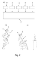
- Fig. 2 b illustrates a running hearing aid user 4' during a training session.
- the hearing aid user 4' is wearing a hearing aid device 2 according to the disclosure.
- the hearing aid device 2 comprises a sensor member (comprising an accelerometer and/or a gyroscope) that detects that the hearing aid user 4' has a high level of physical activity. Therefore, a predefined preferred set of settings P 1 is applied.
- Fig. 2 c illustrates a situation where the hearing aid user 4' has returned from the training session and is relaxing in front of a television.
- the hearing aid user 4' is wearing the same hearing aid device 2 as in Fig. 2 b ). Accordingly, the sensor member detects that the hearing aid user 4' has a low level of physical activity. Therefore, the predefined preferred set of settings is automatically changed from P 1 to P 2 .
- the hearing aid device 2 may comprise means for changing the settings Pi, P 2 (with a predefined speed) over time based on the different input, including the level of physical activity detected by means of the hearing aid device 2. It is possible to have a hearing aid device 2, in which the hearing aid device settings change automatically while the user 4' is wearing the hearing aid device 2 based on measurements from the sensor member. This may be done in combination with simultaneously application of other detectors. In this way it would be possible to change settings when environment parameters change and/or when the level of physical activity of the hearing aid user 4' wearing the hearing aid device 2 changes.
- the settings of the hearing aid device 2 may be optimised for user 4' of the hearing aid device 2. It is possible that the hearing aid device settings slowly adapt over time on the basis of measurements from the accelerometer and/or a gyroscope built-in to the hearing aid device 2. Hereby, these measurements optionally in combination with other detectors may change the hearing aid device settings when environment changes occur or when the activity level of the user 4' changes.
- Measurements from the accelerometer and/or a gyroscope built-in to the hearing aid device 2 may be used as part of a fitting tool, where the activity level might be combined with measurements of the environment provided by the hearing aid device 2 or by another device (e.g. a mobile phone) in a situation where this information define preferences of the user 4'. This may be done while switching between different hearing aid device programs corresponding to different levels of activity as shown in Fig. 2 b) and Fig. 2 c) or when changing the settings in a hearing aid device 2 with a remote control (e.g. implemented as an APP in a mobile phone, e.g. a SmartPhone).
- a remote control e.g. implemented as an APP in a mobile phone, e.g. a SmartPhone
- the hearing aid device settings may be able to automatically adjust to the user's 4' preferences.
- Different user's preferences may be logged by the hearing aid device 2 and collected in a network.
- individual preferences may be further used in the development, where the preferred settings may be logged and used to find optimal settings for other similar users in similar environments.
- the measurements may be analysed by a professional (hearing aid dispenser) and/or be used by the fitting software, and the hearing aid device settings could be individualised based on this.
- the measured activity may also be further labelled, e.g. situations where the user 4' is laying down, running or driving in a car may automatically be detected by the accelerometer and/or a gyroscope built-in to the hearing aid device 2 and be used as specific inputs for the hearing aid settings adjustment.
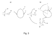
- Fig. 3 a illustrates a schematical top view of a hearing aid user 4 standing next to a loudspeaker 32 sending out sound 34 towards the left ear of the user.
- a hearing aid device 2 is arranged at or in both ears 2.
- Fig. 3 b) illustrates a schematical top view of the hearing aid user 4 shown in Fig. 3 a) turning his head. The head is moved from a first position I to a second position II.
- the accelerometers and/or gyroscopes will detect that the hearing aid devices 2 are moved.
- Artificial sounds 34 in the hearing aid device(s) 2 such as e.g. internal beeps or streamed stereo sounds may be convolved by head-related impulse responses (HRIR) in order to make the sounds appear as coming from a certain direction (such as appearing to the left of the hearing aid user 4).
- HRIR head-related impulse responses
- the accelerometer and/or a gyroscope built-in to the hearing aid device(s) 2 detect the degree of head movement. This information may be used to adaptively change the head-related impulse response in order to create the illusion that the artificial sound 34 appears to be at the same location IV in the room.
- a hearing aid device 2 with a built-in accelerometer and/or gyroscope is able to estimate such movement of the head of the hearing aid user 4. If such a movement is detected, the spatial perception of an artificial sound 34 or any sound which is not directly picked up by the hearing aid microphones may be improved when compensating for the head movement.
- Fig. 3 a illustrates how a built-in accelerometer and/or gyroscope may be used to improve the spatial perception of an artificial sound 34.
- An artificial sound 34 e.g. beep, streamed sound, TV sound signal, telecoil sound or an FM signal comprising a sound signal, e.g. from a microphone
- a head-related impulse response in order to create the illusion that the sound 34 is impinging from a certain direction (such as e.g. to the left side of the head indicated with position IV). If, however the hearing aid user 4 is turning his head, the sound will still seem to impinge from the left side, hereby partly ruining the externalization illusion.
- Continuous information about the degree of head movement obtained by an accelerometer and/or gyroscope may be used to adapt the head-related impulse response towards another direction.
- Fig. 4 a illustrates a schematical view of a hearing aid device 2 provided with an accelerometer and two microphones 38, 38' that are arranged in the same horizontal plane H indicated by a dotted line.
- the hearing aid device 2 is a BTE hearing aid device 2 arranged at or behind the ear 6.
- the hearing aid device is connected to an earpiece arranged in the ear canal via a tube 12.
- the noise reduction (e.g. including a directional) system of a hearing aid device often relies on the assumption that the microphones 38, 38' are actually located in the horizontal plane H as shown in Fig. 4 a) . Accordingly, optimal conditions for processing of the noise reduction (e.g. including a directional) system can be achieved when the microphones 38, 38' are located in the horizontal plane H. This is, however, not always achieved.
- the amount of dislocation can be determined by the accelerometer, and the noise reduction (e.g. including a directional) system may hereby be modified in order to compensate for the sub-optimal mounting.
- the positioning could be optimised in order to improve the performance of different algorithms.
- the accelerometer is able to estimate the direction of the gravity g .
- the positions of the microphones can be compensated based on an instant measurement of position, where the person is looking straight forward, but the position could also be determined as an average position based on how the person actually is carrying the hearing instruments. If e.g. the person most of the time is bending the head forward due to back problems, it is better adjusting the hearing instrument angle according to that.
- the noise reduction (e.g. including a directional) system assumes that the listener is listening to the sound impinging from the front (look direction), and the noise reduction (e.g. including a directional) system is thus optimized in order to provide a flat frequency response from the front direction. If the hearing aid microphones 38, 38' are not located along the horizontal axis H, the noise reduction (e.g. including a directional) system may be modified in order to provide a flat frequency response of the "new" look direction.
- Fig. 4 b illustrates a hearing aid device 2 provided with an accelerometer and arranged in a position in which the microphones 38, 38' are not arranged in the same horizontal plane H.
- the accelerometer will determine the direction of gravity g (e.g. relative to H) and the hearing aid device be configured to compensate for the misalignment (with respect to horizontal) of the microphones 38, 38' by modifying the noise reduction (e.g. including a directional) system.
- the directional microphone coefficients can be changed to an optimal configuration, which takes into account that the microphone configuration is not optimal.
- the noise reduction system comprises a multi-microphone beamformer (e.g. an MVDR beamformer) and a single channel post filter (as e.g. described in [Kjems & Jensen; 2012] (ISSN 2076-1465: Ulrik Kjems and Jesper Jensen, "Maximum likelihood based noise covariance matrix estimation for multi-microphone speech enhancement", 20th European Signal Processing Conference (EUSIPCO 2012), pp. 295-299, 2012 )).
- a multi-microphone beamformer e.g. an MVDR beamformer
- a single channel post filter as e.g. described in [Kjems & Jensen; 2012] (ISSN 2076-1465: Ulrik Kjems and Jesper Jensen, "Maximum likelihood based noise covariance matrix estimation for multi-microphone speech enhancement", 20th European Signal Processing Conference (EUSIPCO 2012), pp. 295-299, 2012 )).
- Fig. 5 a illustrates a view of a hearing aid user 4 wearing a BTE hearing aid device 2 having two microphones that are used to detect the voice of the hearing aid user 4.
- the detection of the voice of the hearing aid user 4 relies on the fact that one microphone is arranged in a larger distance from the mouth 36 than the other microphone. This is the case in Fig. 5 a) since the distance d 2 between the mouth 36 and the furthermost microphone of the hearing aid device 2 is larger than the distance d 1 between the mouth 36 and the nearest microphone of the hearing aid device 2. Because the mouth 36 is close to the hearing aid microphones, an intensity difference between the microphones can be detected. This difference may be used to detect the voice of the hearing aid user 4.
- the hearing aid device 2 is tilted and thus the microphones are no longer arranged in the same horizontal plane.
- the mouth direction may be close to perpendicular to the line crossing the hearing aid microphones.
- the distance d' 2 between the mouth 36 and the furthermost microphone of the hearing aid device 2 basically corresponds to the distance d' 1 between the mouth 36 and the nearest microphone of the hearing aid device 2. Accordingly, the microphones will have basically the same distance (d' 1 ⁇ d' 2 ) to the mouth 36, and the near-field cue for own voice detection is not reliable.
- the hearing aid device 2 comprises an accelerometer
- the direction of the hearing aid microphones can be estimated by means of the accelerometer. Accordingly, based on the detected direction of the hearing aid microphones it can be determined whether or not the own voice cue is reliable.
- the reliability of the own voice detection may be based on the detected direction of the hearing aid microphones of both hearing aid device 2 (left and right) of a binaural hearing aid system. It may be predefined that only in the case that detection for both ears is accessed and only if the angle of the hearing aid microphones with respect to the mouth 36 results in a reliable cue, the detection should be used (assuming that such information can be exchanged between the two hearing aid devices, e.g. via a wireless link, e.g. an interaural, e.g. inductive wireless link). This could e.g. be measured during fitting (or another calibration routine) because the angle should be measured when the person is looking straight ahead.
- a wireless link e.g. an interaural, e.g. inductive wireless link
- Fig. 6 a illustrates a side view of a hearing aid device 2 arranged behind the ear 6 of a hearing aid user.
- the hearing aid device 2 comprises a first microphone 38 and a second microphone 38'.
- the microphones 38, 38' are arranged along a line H s that is not parallel to horizontal plane or direction H.
- the angle ⁇ of the hearing aid device 2 is defined as the angle between the line H s and horizontal H.
- the BTE part and the ear piece of the hearing aid device are connected and arranged in the ear canal via a (typically resilient) tube 12.
- the length of the tube 12 influences the way the BTE part fits behind the ear, and thus also the positioning of the microphones 38, 38'.
- the optimal length of the tube 12 of the hearing aid device 2 can be determined by measuring the angle ⁇ of the hearing aid device 2 based on measurements provided by means of the accelerometer. This is illustrated in Fig. 6 .
- the initial guess of the length of tube 12 is too long and thus the hearing aid device 2 points upwards and the first microphone 38 and the second microphone 38' are not arranged in the same horizontal plane (when the user is standing in an upright position, e.g. on the ground (assuming a vertical direction)).
- the microphones 38, 38' are arranged along a line H s that is not parallel to horizontal H. Therefore, the angle ⁇ is non-zero (positive).
- the accelerometer of the hearing aid device 2 provides measurements of the acceleration acc having components 42, 44.
- the accelerometer of the hearing aid device 2 also detects the direction of gravity g . Based on these measurements the angle ⁇ of the hearing aid device 2 (angle of H s with H) can be established and it can be determined how much the current tube 12 should be adjusted in order to place the hearing aid device 2 in an optimal position.
- Fig. 6 b illustrates another side view of a hearing aid device 2 arranged behind the ear 6 of a hearing aid user.
- the initial tube 12 guess is too short and thus the hearing aid device 2 points downwards (the angle ⁇ between directions H s and H has an opposite sign than in the example of FIG. 6 a) ).
- the first microphone 38 and the second microphone 38' are not arranged in the same horizontal plane.
- the microphones 38, 38' are arranged along a line H s that is not parallel to horizontal H. Accordingly, the angle ⁇ is non-zero (negative). Based thereon, it can be determined how much the current tube 12 should be adjusted in order to place the hearing aid device 2 in an optimal position.
- Fig. 6 c illustrates another side view of a hearing aid device 2 arranged behind the ear 6 of a hearing aid user.
- the length of the tube 12 is optimal and thus both the first microphone 38 and the second microphone 38' are arranged in the horizontal plane H.
- the microphones 38, 38' are arranged along a line H s that is parallel to horizontal H. Accordingly, the angle ⁇ between H s and H is zero.
- the accelerometer of the hearing aid device 2 detects the direction of gravity g and the angle ⁇ of the hearing aid device 2. It can be verified that the current tube 12 has an optimum length and that no adjustment either of the length of the tube 12 or the position of the hearing aid device 2 is required.
- Based on the measured angle ⁇ of the hearing aid device 2 may similarly be applied to determine the optimal cable length of a (resilient, semirigid) electric cable connecting a BTE part and a loudspeaker located in the ear canal and electrically driven from (a processor of) the BTE part of the hearing aid device (e.g. a hearing aid device of the 'Receiver In The Ear' (RITE) type).
- a processor of the BTE part of the hearing aid device e.g. a hearing aid device of the 'Receiver In The Ear' (RITE) type.
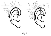
- Fig. 7 a illustrates a hearing aid device 2 provided with a small actuator 46 configured to change the orientation (inclination) of the hearing aid microphones 38, 38'.
- the actuator 46 is capable of bringing the hearing aid microphones 38, 38' into an optimal position.
- the hearing aid device 2 has a built-in accelerometer 8 adapted to determine the direction of gravity g and the orientation of the hearing aid device 2 relative to the direction of gravity g .
- Fig. 7 a the hearing aid microphones 38, 38' are arranged along a line H s that is parallel to horizontal H. Thus, there is no need to adjust the position of the microphones 38, 38' relative to each other.
- the actuator 46 is indicated with a dotted line in the first position I.
- the actuator 46 is indicated with a solid line in the second position II.
- the actuator 46 brings the hearing aid microphones 38, 38' from the first position I into the second position II and hereby bringing the hearing aid microphones 38, 38' into the desired position.
- the angular displacement of the line (H s ) crossing the hearing aid microphones 38, 38' corresponds to the indicated angle ⁇ .
- the hearing aid microphones 38, 38' are arranged along the non-horizontal line H s and the expected direction of gravity 42 does not correspond to the direction of gravity g .
- Gravity g indicated as a vector g corresponds to the sum of the components 42 and 44.
- Fig. 7 a) and Fig. 7 b) illustrate a hearing aid device 2 equipped with a small actuator 46 able to adjust the hearing aid microphones 38, 38' into e.g. a position where the hearing aid microphones 38, 38' are positioned in the same horizontal plane H, hereby optimising the effect of the directionality and/or the own voice detection of the hearing aid device 2.
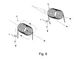
- Fig. 8 illustrates two coils 48, 48' arranged in a hearing system comprising two (first and second) hearing aid devices.
- the coils 48, 48' may be used to provide communication between the hearing aid devices via magnetic inductance.
- the distance between the hearing aids may also be determined on the basis of the received signal power (or signal strength; signal strength falls off with d 3 (signal power with d 6 ) where d is the distance between the exiting an the exited coils).
- the received signal strength by a second inductive coil from a first coil depends on the mutual orientations of the two coils. An optimum mutual induction between the two coils can be achieved, if the longitudinal directions of the coils are parallel (as is nearly the case in Fig. 8 ). If not, the mutual induction is decreased from the optimum.
- the distance may be determined more accurately if the angle ⁇ between the hearing aid devices (e.g. the coil antennas 48, 48') is determined (based on the transmitted and received signal strength and the angle a).
- the angle ⁇ may be determined on the basis of the direction of the acceleration acc in each hearing aid device.
- Fig. 8 illustrates how the angle ⁇ between two accelerometers - one in each hearing aid device can be used to improve the calculation of the distance between the two ears based on the strength of the interaural magnetic inductance.
- a hearing system comprising two hearing aid devices is equipped with accelerometers capable of determining the acceleration acc in each hearing aid device and to compare the direction of the detected the acceleration vectors acc ( acc1, acc2 ) to the direction of gravity g .
- Fig. 9 a illustrates a schematical top view of a hearing aid user 4 (wearing hearing aid devices 2, 2' at his left and right ear, respectively) standing in front of two individuals 5, 5' that are talking to him. Two individuals 5", 5"' are talking to each other in the hatched area behind the hearing aid user 4.
- Fig. 9 b illustrates a schematical top view of the hearing aid user 4 from Fig. 9 a) in a similar situation but where he is turning his head clockwise (cf. curved arrow).
- Each of the hearing aid devices 2, 2' comprises an accelerometer and/or a gyroscope that is configured to detect the acceleration of the hearing aids 2, 2' and thus the acceleration of the hearing aid user 4.
- Fig. 9 b shows a situation in which the hearing aid user 4 turns his head.
- spatial algorithms in the hearing aid devices 2, 2' e.g. a noise reduction (e.g. including a directional) algorithm for defining a resulting microphone characteristic, a noise reduction algorithm, or a feedback estimation algorithm
- the accelerometers and/or gyroscopes in the hearing aid devices are able to detect head movements. Based on the detected acceleration it is possible to adjust the adaptation speed for the adaptive algorithm applied within the hearing aid devices 2, 2'.
- the detected acceleration/movement can be used to provide the spatial algorithms with information concerning the change of the acoustic surrounding. Accordingly, the spatial algorithms can increase the adaptation speed for a while in order to provide a fast adaptation to the new acoustic environment.
- the directions to be attenuated by the hearing aid are indicated as the non-hatched the area.
- Both hearing aid devices 2, 2' detect sound from the surroundings of the hearing aid user.
- the hearing aid user 4 moves the head, it would be beneficial to have a 360 degree sound scene mapping corresponding to the movement of the head of the hearing aid user 4.
- Hearing instruments traditionally use directionality to emphasize sounds from the front and attenuate sounds from the sides and the back. Some systems, however, allow switching of focus to the sides or the back. In reality, the hearing aid user 4 will constantly turn the head to attend to objects of interest and the acoustic focus direction will turn with the head movements causing the focus sound source (e.g. the person 5 speaking) to get out of focus. The result is reduction or fluctuating audibility and intelligibility.
- a hearing aid system comprising two hearing aid devices 2, 2' that are configured to work together (supported by wireless interaural communication between them).
- the hearing aid system detects the movement and adjusts the focus direction(s) accordingly, to maintain audibility and intelligibility of the focus source 5 (or sources 5, 5', 5", 5"', in case all four sources 5, 5', 5", 5"' are defined as focus sources).
- the focus sources illustrated in Fig. 9 are individuals 5, 5', 5", 5"'.
- the focus sources may be a sound source (e.g. a person 5 speaking) primarily in front of the hearing aid user 5 (e.g. based on angle detections).
- the focus sources may be multiple sound sources (e.g. persons 5, 5' speaking) prioritised according to the time the hearing aid user 4 spends focusing the head in the direction of the sound source.
- the focus sources may be one or more sound sources that the hearing aid user 4 points out manually using a pointer device (not shown, e.g. a remote control device, e.g. implemented as an APP running on a SmartPhone).
- the hearing aid devices 2, 2' (alone or in combination with another device, e.g. a remote control, e.g. a SmartPhone, in communication with the hearing aid devices) individually map (overlapping) parts of the sound scene and exchange information about directions and sound characteristics with the other hearing aid devices 2, 2' (and possibly with other connected devices). This will allow the other hearing aid device 2, 2' to recognise the sound sources 5, 5', 5", 5"', when they enter their scope of acoustic view when the hearing aid user 4 is turning his head as illustrated in Fig. 9 b) .
- a remote control e.g. a SmartPhone
- the sound scene mapping may be constantly shared between the hearing aid devices 2, 2' and other connected devices.
- the directionality system in each hearing aid device 2, 2' may be constantly adjusted in order to give higher loudness to the focus sound sources 5, 5', 5", 5"'.
- the degree of prioritisation of focus sources may be automatically adapted according to environmental conditions and personal preference settings of the hearing aid user 4.
- Hearing aid devices 2 are small and expensive. Due to their small size and weight, it may not be noticed if the hearing aid device 2 is dropped and the hearing aid device 2 may not be easy to find.
- a hearing aid device 2 that is configured to communicate with a mobile phone (e.g. a SmartPhone) 40 when a hearing aid device 2 is falling is a major advantage.
- the hearing aid device 2 should comprise an accelerometer and/or gyroscope adapted to detect when the hearing aid device 2 is dropped.
- One possible criterion to determine that the hearing aid device 2 is dropped may be the detection of an acceleration corresponding to the acceleration of the force of gravity for a predefined time period e.g. a time period corresponding to that the hearing aid device 2 is moved more than 50 cm, e.g. more than 100 cm downwards in the vertical direction (this depends on the initial speed of the hearing aid device 2).
- Fig. 10 a illustrates a situation where a hearing aid device 2 is dropped by mistake by a hearing aid user 4 that is running.
- the hearing aid device 2 is provided with a free fall detector that sends a signal 35 to a mobile phone 40, e.g. a SmartPhone.
- the mobile phone 40 comprises a GPS device that receives Global Positioning System (GPS) signals to determine the location of the hearing aid device 2 and means to log the position where the hearing aid device 2 was lost.
- GPS Global Positioning System
- the hearing aid device 2 and the mobile phone 40 constitute an alarm system using a free fall detector that is indicating when and where the hearing aid device 2 is dropped.
- Many standard mobile phones on the market today have a built-in GPS device and means for storing a position where the GPS device has been used.
- Fig. 10 b illustrates a situation in which a hearing aid device 2 is dropped by a running hearing aid user 4.
- the hearing aid device 2 comprises an accelerometer and/or a gyroscope configured to determine the acceleration of the hearing aid device 2.
- the accelerometer and/or gyroscope constitute a free fall detector that sends a signal 35 to the other hearing aid device 2' of a binaural hearing aid system immediately after the hearing aid device 2 is dropped. This alarm signal is provided in the other hearing aid device 2' so that the hearing aid user 4 is warned by an audio signal.
- the acceleration patterns or the free fall detection could be interchanged. Hereby it can be detected if one or both hearing instruments are dropped. Only if one instrument is dropped, a warning in the opposite hearing instrument is necessary.
- the hearing aid user 4 is aware that the hearing aid device 2 has been lost.
- the alarm signal may also be also be displayed on the mobile phone 40 that the hearing aid user 4 is holding in his left hand or sent to a communication device of a caretaker. This may be beneficial for a caretaker to be noticed on her phone, e.g. if a child has lost a hearing aid device 2.
- the hearing aid device 2 may send a signal 35 to the mobile phone 40 that may comprise a GPS device so that the position where the hearing aid device 2 was lost can be logged.
- the mobile phone may assist to localise the spot, at which the hearing aid device 2 was lost.
- the hearing aid device 2 may comprise means for logging the last position where a wireless link was established between the two hearing aid devices 2, 2' or between the lost hearing aid device 2 and the mobile phone 40.
- the hearing aid device 2 is configured to provide a warning, which may be triggered even before a wireless link is lost, and hereby increasing the probability of noticing when and where the hearing aid was lost.
- An accelerometer and/or gyroscope built-in to the hearing aid device 2, 2' can be used to estimate if the hearing aid device is dropped (free fall detection).
- the hearing aid device 2 When the hearing aid device 2 is dropped through the air, a free fall is detected by the accelerometer and/or gyroscope, and the other hearing aid device 2' can be alarmed immediately. Furthermore, if the hearing aid user 4 is wearing a GPS device, e.g. a mobile phone with a built-in GPS device, the position of where the hearing aid device was dropped may be logged in the mobile phone 40, and afterwards be used to assist the hearing aid user 4 in tracking his hearing aid device 2. After a free fall has been detected, and it has been detected that the hearing instrument has had an impact and is lying without further movement, the hearing instrument can go into a low power mode, where the battery power solely is used for transmitting a wireless signal with maximum strength, hereby making it easier to localize the hearing instrument. E.g., the hearing instrument could transmit such a localization signal once every second in order to prolong the battery time and hereby increasing the probability of being found.
- a GPS device e.g. a mobile phone with a built-in GPS device
- the mobile phone 40 is configured to provide an alarm signal that is sent to an external device (e.g. a mobile phone of a caretaker or a server).
- an external device e.g. a mobile phone of a caretaker or a server.
- an automatic microphone matching routine should preferably be run after such a shock has been detected. This could be done e.g. by increasing the adaptation time of the automatic microphone matching system, or it could be done during a calibration of the hearing aid device.
- Some or all of the following data could preferably be detected and logged in a database.
- the determination of the parameters is based on the possibility of measuring acceleration in the hearing aid device(s).
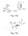
- Pitch, yaw and roll represent angles of rotation around respective orthogonal axes of a center of mass of an aircraft.
- these terms are used for a head of a user of a hearing aid device or a binaural hearing aid system comprising left and right hearing aid devices adapted for being located at or in left and right ears of a user respectively.
- a definition of the rotational movement parameters pitch, yaw and roll relative to the x, y and z axis of an orthogonal coordinate system is illustrated in the left graph of Fig. 11a .
- Roll is defined as a rotation around the x-axis.
- Pitch is defined as a rotation around the y-axis.
- Yaw is defined as a rotation around the z-axis.
- the corresponding parameters are exemplified relative to a head of a user in the right graph of Fig. 11a .
- Pitch is defined as a rotation of the head around the x-axis. Can be measured by either a single or a pair of hearing aid devices. A gyroscope in a hearing aid device can measure it directly. Measurements from a pair of gyroscopes in each their hearing aid device can be averaged to provide higher precision. An accelerometer will measure the direction of the gravity field and the pitch can then be determined by calculation of the difference between the actual directions of the gravity and a previous determined 'normal' direction i.e. the established z-axis. If two hearing aids both estimate pitch, they can combine their results for better precision.
- Yaw is defined as a rotation of the head around the y-axis. Can be measured by either a single or a pair of hearing aid devices. A gyroscope in a hearing aid device can measure it directly. Measurements from a pair of gyroscopes, one in each hearing aid device can be compared (e.g. averaged) to provide higher precision. With an accelerometer there are two ways to estimate yaw or more exact angular velocity ⁇ .
- a second way of estimating the angular velocity ⁇ is based on integration of the linear acceleration a x orthogonal to the radius of the movement as illustrated in Fig. 12a .
- Verlet or 4 th order Runge Kutta should advantageously be considered.
- Roll is defined as a rotation around the x-axis. Roll can be determined as yaw but using acceleration in the z-plane instead of the x-plane. But additionally, the gravity method used for 'Pitch' can also be applied here.
- This example deals with achieving a higher accuracy for linear head movement estimates using two or more accelerometers. If the acceleration measured in the same geometric plane by a pair or more accelerometers are averaged, the precision increases and unwanted rotational information can be removed.
- This example deals with estimating the distance between the hearing aids. If at least one accelerometer and one gyroscope are present (either in one hearing aid or in a pair), it is possible to estimate the distance from the center of rotation to the sensors.
- the center of rotation is following a normal distribution it is possible to estimate the radius and so the distance between the hearing aids (2xradius) by averaging a large number of radius values r.
- This example deals with overall necessary conditions when using sensors distributed in more devices as for example a pair of hearing aids where it is necessary to be able to exchange and analyze the data.
- the links between the devices are preferable wireless, but can also be established via wired connections.
- the data must be synchronized in time between the devices to ensure that the data to be analyzed are aligned in time.
- the analysis can take place in each device, in one device that transmits the result to the other devices, or distributed over more devices.
- the center of rotation is located on an imaginary line drawn between a pair of hearing aids. In reality we suspect that the center of rotation 'O' is placed off-line as indicated in Fig. 13 . This means that the estimate of angular velocity ⁇ is less accurate using integration of acceleration if no correction is applied. The gravity and the centripetal method are still correct even with 'O' off-line.
- Hearing aid device users often forget to turn their hearing instruments off and then the limited battery power is wasted. Especially rechargeable batteries have limited battery life. Users that have reduced dexterity and eye sight, find it difficult to turn on hearing instruments, with small buttons and battery drawers. Finally the hearing instrument can start hauling during insertion into the ear canal, if the gain is on before it is placed on/in the ear. There is thus a need for an 'intelligent' on-off mechanism for hearing aid devices.
- a movement detector e.g. an accelerometer built into the hearing instrument is able to detect if the hearing aid device is being moved and how it is moved (fast/slow, up/down, etc.). In a simple use case, this can be used to detect that the user has taken the hearing instrument out and left it on a table and the hearing instrument can be configured to automatically turn off or be put into a 'low-power' or 'sleep mode', where the power consumption is minimal.
- the user picks up the hearing instrument e.g. the next morning
- the movement sensor it is automatically turned on, e.g. in a 'standby mode', and when it is placed into the ear, the gain is automatically turned on.
- the detection using the accelerometer can be combined with a range of different detections for better and more reliable 'on-ear-detection'.
- Other detections could be:
- the first suggested version of the disclosure (system A) is mainly based on the accelerometer itself, combined with a timer. See Fig. 14a and sections A1, A2, A3, A4 below.
- the hearing instrument When the battery is placed in the hearing instrument, the hearing instrument is configured to start up in a standby mode where the power consumption is minimal.
- the accelerometer In a full automatic version, the accelerometer is used to detect that the hearing instrument is placed on the ear and then power up fully with full gain. The following three detections could preferably to be present:
- the hearing instrument can be woken up by tapping the hearing instrument with the fingers. This is detected by the accelerometer of the hearing instrument, which is powered up and full gain applied.
- the following detections are preferably present:
- the hearing instrument When the battery is placed in the hearing instrument, the hearing instrument is configured to start up in a 'standby mode', where the power consumption is minimal.
- the movement sensor e.g. an accelerometer
- the hearing instrument is placed on the ear and then configured to power up fully with full gain.
- the following three or four detections could preferably be present:
- the in-ear detection can also be combined with the own voice detection for a more reliable detection.
Priority Applications (11)
| Application Number | Priority Date | Filing Date | Title |
|---|---|---|---|
| EP14155022.8A EP2908549A1 (de) | 2014-02-13 | 2014-02-13 | Hörgerätevorrichtung mit Sensorelement |
| DK15154417.8T DK2908550T3 (en) | 2014-02-13 | 2015-02-10 | Hearing aid device comprising a sensor element |
| EP18165433.6A EP3370435B1 (de) | 2014-02-13 | 2015-02-10 | Hörgerätevorrichtung mit einem sensorelement |
| EP15154417.8A EP2908550B1 (de) | 2014-02-13 | 2015-02-10 | Hörgerätevorrichtung mit Sensorelement |
| US14/620,685 US9596551B2 (en) | 2014-02-13 | 2015-02-12 | Hearing aid device comprising a sensor member |
| US15/420,268 US9826318B2 (en) | 2014-02-13 | 2017-01-31 | Hearing aid device comprising a sensor member |
| US15/790,523 US10524061B2 (en) | 2014-02-13 | 2017-10-23 | Hearing aid device comprising a sensor member |
| US16/678,567 US11128961B2 (en) | 2014-02-13 | 2019-11-08 | Hearing aid device comprising a sensor member |
| US17/399,667 US11533570B2 (en) | 2014-02-13 | 2021-08-11 | Hearing aid device comprising a sensor member |
| US17/983,733 US11889265B2 (en) | 2014-02-13 | 2022-11-09 | Hearing aid device comprising a sensor member |
| US18/538,844 US20240121561A1 (en) | 2014-02-13 | 2023-12-13 | Hearing aid device comprising a sensor member |
Applications Claiming Priority (1)
| Application Number | Priority Date | Filing Date | Title |
|---|---|---|---|
| EP14155022.8A EP2908549A1 (de) | 2014-02-13 | 2014-02-13 | Hörgerätevorrichtung mit Sensorelement |
Publications (1)
| Publication Number | Publication Date |
|---|---|
| EP2908549A1 true EP2908549A1 (de) | 2015-08-19 |
Family
ID=50073060
Family Applications (3)
| Application Number | Title | Priority Date | Filing Date |
|---|---|---|---|
| EP14155022.8A Withdrawn EP2908549A1 (de) | 2014-02-13 | 2014-02-13 | Hörgerätevorrichtung mit Sensorelement |
| EP18165433.6A Active EP3370435B1 (de) | 2014-02-13 | 2015-02-10 | Hörgerätevorrichtung mit einem sensorelement |
| EP15154417.8A Active EP2908550B1 (de) | 2014-02-13 | 2015-02-10 | Hörgerätevorrichtung mit Sensorelement |
Family Applications After (2)
| Application Number | Title | Priority Date | Filing Date |
|---|---|---|---|
| EP18165433.6A Active EP3370435B1 (de) | 2014-02-13 | 2015-02-10 | Hörgerätevorrichtung mit einem sensorelement |
| EP15154417.8A Active EP2908550B1 (de) | 2014-02-13 | 2015-02-10 | Hörgerätevorrichtung mit Sensorelement |
Country Status (3)
| Country | Link |
|---|---|
| US (7) | US9596551B2 (de) |
| EP (3) | EP2908549A1 (de) |
| DK (1) | DK2908550T3 (de) |
Cited By (11)
| Publication number | Priority date | Publication date | Assignee | Title |
|---|---|---|---|---|
| CN106358131A (zh) * | 2016-08-29 | 2017-01-25 | 苏州倍声声学技术有限公司 | 一种骨传导助听器 |
| EP3229494A1 (de) * | 2016-04-06 | 2017-10-11 | Sivantos Pte. Ltd. | Verfahren zur physischen anpassung eines hörgeräts, hörgerät und hörgerätesystem |
| WO2017207044A1 (en) | 2016-06-01 | 2017-12-07 | Sonova Ag | Hearing assistance system with automatic side detection |
| EP3355593A1 (de) * | 2017-01-30 | 2018-08-01 | Sivantos Pte. Ltd. | Verfahren zum betreiben einer hörhilfevorrichtung und hörhilfevorrichtung |
| US10356542B2 (en) | 2014-05-28 | 2019-07-16 | Advanced Bionics Ag | Auditory prosthesis system including sound processor apparatus with position sensor |
| EP3576433A1 (de) * | 2018-05-30 | 2019-12-04 | Sivantos Pte. Ltd. | Verfahren zur verringerung eines auftretens einer akustischen rückkopplung in einem hörgerät |
| DE102018209801A1 (de) * | 2018-06-18 | 2019-12-19 | Sivantos Pte. Ltd. | Verfahren zum Betrieb eines Hörvorrichtungssystems und Hörvorrichtungssystem |
| US10623871B2 (en) | 2016-05-27 | 2020-04-14 | Sonova Ag | Hearing assistance system with automatic side detection |
| EP3684076A3 (de) * | 2019-03-29 | 2020-11-18 | Sonova AG | Beschleunigungsmesserbasierte auswahl einer audioquelle für ein hörgerät |
| WO2021144031A1 (en) | 2020-01-17 | 2021-07-22 | Sonova Ag | Hearing system and method of its operation for providing audio data with directivity |
| WO2024051970A1 (de) * | 2022-09-08 | 2024-03-14 | Sivantos Pte. Ltd. | Verfahren zur anpassung einer hörvorrichtung |
Families Citing this family (76)
| Publication number | Priority date | Publication date | Assignee | Title |
|---|---|---|---|---|
| KR102175180B1 (ko) * | 2013-09-04 | 2020-11-05 | 삼성전자주식회사 | 자세 검출에 기반한 피드백 방지 방법 및 상기 방법을 수행할 수 있는 장치들 |
| EP2908549A1 (de) | 2014-02-13 | 2015-08-19 | Oticon A/s | Hörgerätevorrichtung mit Sensorelement |
| EP2928210A1 (de) * | 2014-04-03 | 2015-10-07 | Oticon A/s | Binaurales Hörgerätesystem mit binauraler Rauschunterdrückung |
| EP2991380B1 (de) * | 2014-08-25 | 2019-11-13 | Oticon A/s | Hörhilfevorrichtung mit einer standortidentifizierungseinheit |
| EP3451705B1 (de) * | 2014-11-19 | 2020-10-14 | Sivantos Pte. Ltd. | Verfahren und vorrichtung zum schnellen erkennen der eigenen stimme |
| US10609475B2 (en) | 2014-12-05 | 2020-03-31 | Stages Llc | Active noise control and customized audio system |
| WO2016145261A1 (en) * | 2015-03-10 | 2016-09-15 | Ossic Corporation | Calibrating listening devices |
| DE102015204639B3 (de) * | 2015-03-13 | 2016-07-07 | Sivantos Pte. Ltd. | Verfahren zum Betrieb eines Hörgeräts sowie Hörgerät |
| US11426592B2 (en) * | 2015-05-14 | 2022-08-30 | Cochlear Limited | Functionality migration |
| US9844700B1 (en) * | 2015-06-14 | 2017-12-19 | Grady Burleson, Jr. | Avalanche self-rescue device |
| US9723415B2 (en) * | 2015-06-19 | 2017-08-01 | Gn Hearing A/S | Performance based in situ optimization of hearing aids |
| US9661426B2 (en) * | 2015-06-22 | 2017-05-23 | Gn Hearing A/S | Hearing aid having combined antennas |
| DE102015219582A1 (de) * | 2015-10-09 | 2016-11-17 | Sivantos Pte. Ltd. | Verfahren zum Betrieb eines Hörgerätesystems und Hörgerätesystem |
| DE102015219581A1 (de) * | 2015-10-09 | 2016-11-17 | Sivantos Pte. Ltd. | Verfahren zum Betrieb eines Hörgerätesystems und Hörgerätesystem |
| DE102015219572A1 (de) * | 2015-10-09 | 2017-04-13 | Sivantos Pte. Ltd. | Verfahren zum Betrieb einer Hörvorrichtung und Hörvorrichtung |
| US9913050B2 (en) | 2015-12-18 | 2018-03-06 | Cochlear Limited | Power management features |
| EP3185588A1 (de) * | 2015-12-22 | 2017-06-28 | Oticon A/s | Hörgerät mit einem rückkopplungsdetektor |
| US9749766B2 (en) * | 2015-12-27 | 2017-08-29 | Philip Scott Lyren | Switching binaural sound |
| EP3214856A1 (de) * | 2016-03-01 | 2017-09-06 | Oticon A/s | Für den betrieb in einem kommunikationssystem konfiguriertes hörgerät |
| EP3427495B1 (de) * | 2016-03-11 | 2023-08-09 | Sonova AG | Hörhilfevorrichtung und verfahren mit automatischer sicherheitskontrolle |
| CN108781320B (zh) * | 2016-03-14 | 2020-08-04 | 索诺瓦公司 | 具有丢失检测功能的无线身体佩戴式个人设备 |
| US11223910B2 (en) * | 2016-03-29 | 2022-01-11 | Cochlear Limited | Algorithm and wearing option interaction with a vibratory prosthesis |
| US10616695B2 (en) * | 2016-04-01 | 2020-04-07 | Cochlear Limited | Execution and initialisation of processes for a device |
| WO2017197156A1 (en) | 2016-05-11 | 2017-11-16 | Ossic Corporation | Systems and methods of calibrating earphones |
| US9848273B1 (en) | 2016-10-21 | 2017-12-19 | Starkey Laboratories, Inc. | Head related transfer function individualization for hearing device |
| US10945080B2 (en) | 2016-11-18 | 2021-03-09 | Stages Llc | Audio analysis and processing system |
| EP3552407A4 (de) | 2016-12-09 | 2020-07-15 | The Research Foundation for The State University of New York | Fasermikrofon |
| US10507137B2 (en) * | 2017-01-17 | 2019-12-17 | Karl Allen Dierenbach | Tactile interface system |
| US10133544B2 (en) | 2017-03-02 | 2018-11-20 | Starkey Hearing Technologies | Hearing device incorporating user interactive auditory display |
| US20190028817A1 (en) * | 2017-07-20 | 2019-01-24 | Wizedsp Ltd. | System and method for a directional speaker selection |
| US10771883B2 (en) * | 2018-02-07 | 2020-09-08 | Eargon, Inc. | Hearing assistance device that uses one or more sensors to autonomously change a power mode of the device |
| US11546731B2 (en) | 2018-02-28 | 2023-01-03 | Cochlear Limited | Locating wireless devices |
| DE102018206979A1 (de) * | 2018-05-04 | 2019-11-07 | Sivantos Pte. Ltd. | Verfahren zum Betrieb eines Hörgeräts und Hörgerät |
| DE102018206975A1 (de) * | 2018-05-04 | 2019-11-07 | Sivantos Pte. Ltd. | Verfahren zum Betrieb eines Hörgeräts und Hörgerät |
| US11438707B2 (en) | 2018-05-11 | 2022-09-06 | Sivantos Pte. Ltd. | Method for operating a hearing aid system, and hearing aid system |
| DE102018207343A1 (de) * | 2018-05-11 | 2019-11-14 | Sivantos Pte. Ltd. | Verfahren zum Betrieb eines Hörsystems sowie Hörsystem |
| WO2021089108A1 (de) * | 2019-11-04 | 2021-05-14 | Sivantos Pte. Ltd. | Verfahren zum betrieb eines hörsystems sowie hörsystem |
| EP3576434A1 (de) * | 2018-05-30 | 2019-12-04 | Oticon A/s | Körpertemperaturhörgerät |
| EP3588983B1 (de) | 2018-06-25 | 2023-02-22 | Oticon A/s | Hörgerät zur anpassung von eingangswandlern unter verwendung der stimme eines trägers des hörgeräts |
| US10795638B2 (en) | 2018-10-19 | 2020-10-06 | Bose Corporation | Conversation assistance audio device personalization |
| US11089402B2 (en) * | 2018-10-19 | 2021-08-10 | Bose Corporation | Conversation assistance audio device control |
| DK3668116T3 (da) * | 2018-12-11 | 2022-04-19 | Gn Hearing As | På hovedet bærbar høreindretning med stødaktiveret genstart |
| US11317222B2 (en) | 2019-12-17 | 2022-04-26 | Gn Hearing A/S | Method of determining a status of an acoustic feedback path of a head wearable hearing device and a head wearable hearing device |
| CN109889966A (zh) * | 2019-03-07 | 2019-06-14 | 钰太芯微电子科技(上海)有限公司 | 基于微机电系统的骨传导传感器 |
| EP3709115B1 (de) | 2019-03-13 | 2023-03-01 | Oticon A/s | Hörgerät oder system mit einer benutzeridentifizierungseinheit |
| CN109756813A (zh) * | 2019-03-19 | 2019-05-14 | 南昌科悦企业管理咨询有限公司 | 一种便于佩戴防掉落的蓝牙耳机 |
| EP3716648A1 (de) * | 2019-03-27 | 2020-09-30 | Sonova AG | Hörgerät und verfahren zur steuerung eines leistungsmodus davon |
| US10638210B1 (en) * | 2019-03-29 | 2020-04-28 | Sonova Ag | Accelerometer-based walking detection parameter optimization for a hearing device user |
| DK3684079T3 (da) * | 2019-03-29 | 2024-04-15 | Sonova Ag | Høreapparat til orienteringsestimering og metode til dets drift |
| EP4184949A1 (de) | 2019-04-17 | 2023-05-24 | Oticon A/s | Hörgerät mit einem sender |
| WO2020225644A1 (en) * | 2019-05-07 | 2020-11-12 | Cochlear Limited | Noise cancellation for balance prosthesis |
| CN113490524A (zh) | 2019-06-17 | 2021-10-08 | 科利耳有限公司 | 音频设备的接受者的音乐感知的改善 |
| EP3817404A3 (de) * | 2019-10-09 | 2021-07-14 | Oticon A/s | Mit ohrschale verbundene hörgerätebatterie |
| CN111079112B (zh) * | 2019-12-06 | 2022-06-03 | 北京小米移动软件有限公司 | 应用控制方法、应用控制装置及存储介质 |
| EP4085654A1 (de) | 2019-12-31 | 2022-11-09 | Starkey Laboratories, Inc. | Verfahren und systeme zur bewertung der einsetzposition einer ohrinternen anordnung eines hörgeräts |
| US11579165B2 (en) | 2020-01-23 | 2023-02-14 | Analog Devices, Inc. | Method and apparatus for improving MEMs accelerometer frequency response |
| US10993045B1 (en) | 2020-03-30 | 2021-04-27 | Sonova Ag | Hearing devices and methods for implementing automatic sensor-based on/off control of a hearing device |
| US11228853B2 (en) * | 2020-04-22 | 2022-01-18 | Bose Corporation | Correct donning of a behind-the-ear hearing assistance device using an accelerometer |
| US11200876B2 (en) * | 2020-05-14 | 2021-12-14 | Bose Corporation | Activity-based smart transparency |
| DE102020207585A1 (de) | 2020-06-18 | 2021-12-23 | Sivantos Pte. Ltd. | Hörsystem mit mindestens einem am Kopf des Nutzers getragenen Hörinstrument sowie Verfahren zum Betrieb eines solchen Hörsystems |
| DE102020209050B4 (de) * | 2020-07-20 | 2022-05-25 | Sivantos Pte. Ltd. | Verfahren zum Betrieb eines Hörsystems, Hörsystem, Hörgerät |
| EP3955595A1 (de) * | 2020-08-10 | 2022-02-16 | Oticon Medical A/S | Hörgerät mit sensor zum detektieren einer ausrichtung der hörgerätemikrofone |
| TWI824177B (zh) * | 2020-09-03 | 2023-12-01 | 鉭騏實業有限公司 | 多功能居家檢測助聽裝置及其方法 |
| US11115746B1 (en) * | 2020-09-25 | 2021-09-07 | Apple Inc. | Dynamic latching of hinged devices |
| US11617044B2 (en) | 2021-03-04 | 2023-03-28 | Iyo Inc. | Ear-mount able listening device with voice direction discovery for rotational correction of microphone array outputs |
| US11570539B2 (en) | 2021-03-20 | 2023-01-31 | International Business Machines Corporation | Safeguarding audio device based on detection of freefall or lost scenarios |
| EP4064730A1 (de) * | 2021-03-26 | 2022-09-28 | Oticon A/s | Bewegungsdatenbasierte signalverarbeitung |
| US11729540B2 (en) | 2021-12-16 | 2023-08-15 | Starkey Laboratories, Inc. | Water immune user-actuatable touch control for an ear-worn electronic device |
| EP4210348A1 (de) | 2022-01-06 | 2023-07-12 | Oticon A/s | Verfahren zur überwachung und erkennung, ob hörgeräte korrekt montiert sind |
| US11832059B2 (en) | 2022-02-10 | 2023-11-28 | Semiconductor Components Industries, Llc | Hearables and hearing aids with proximity-based adaptation |
| WO2023230588A1 (en) * | 2022-05-25 | 2023-11-30 | Earable, Inc. | Headband with bone conduction speakers |
| EP4340387A1 (de) * | 2022-09-13 | 2024-03-20 | GN Audio A/S | Kopfhörer und verfahren zur durchführung eines befehls durch einen kopfhörer |
| WO2024067994A1 (de) * | 2022-09-30 | 2024-04-04 | Mic Audio Solutions Gmbh | System und verfahren zum verarbeiten von mikrofonsignalen |
| EP4351171A1 (de) * | 2022-10-04 | 2024-04-10 | Oticon A/s | Hörgerät mit einer lautsprechereinheit |
| EP4354903A1 (de) | 2022-10-11 | 2024-04-17 | Oticon A/s | Optimierung der positionierung und konfiguration eines hörgeräts |
| EP4300996A1 (de) * | 2023-01-04 | 2024-01-03 | Oticon A/s | Verwendung einer spezifischen kopfneigung zur steuerung der hörgerätefunktion |
Citations (3)
| Publication number | Priority date | Publication date | Assignee | Title |
|---|---|---|---|---|
| US6330339B1 (en) | 1995-12-27 | 2001-12-11 | Nec Corporation | Hearing aid |
| WO2009049646A1 (en) * | 2007-10-16 | 2009-04-23 | Phonak Ag | Method and system for wireless hearing assistance |
| EP1530402B1 (de) | 2003-11-05 | 2009-07-01 | Siemens Audiologische Technik GmbH | Verfahren zur Adaption eines Hörgeräts unter Berücksichtigung der Kopfposition und entsprechendes Hörgerät |
Family Cites Families (31)
| Publication number | Priority date | Publication date | Assignee | Title |
|---|---|---|---|---|
| US4318245A (en) * | 1980-01-22 | 1982-03-09 | The Quaker Oats Company | Vocalizing apparatus |
| CA2207184A1 (en) * | 1997-05-27 | 1998-11-27 | Eugene Alexandrescu | Hearing instrument with head activated switch |
| DE19810043A1 (de) * | 1998-03-09 | 1999-09-23 | Siemens Audiologische Technik | Hörgerät mit einem Richtmikrofon-System |
| WO2002098169A1 (en) | 2001-05-30 | 2002-12-05 | Aliphcom | Detecting voiced and unvoiced speech using both acoustic and nonacoustic sensors |
| DE10148006A1 (de) | 2001-09-28 | 2003-06-26 | Siemens Ag | Tragbare Schallwiedergabeeinrichtung zur Erzeugung eines dreidimensionalen Höreindrucks |
| EP1825712B1 (de) | 2004-12-16 | 2010-03-03 | Widex A/S | Hörgerät mit modellierter rückkopplungsverstärkungsschätzung |
| DE102005032274B4 (de) | 2005-07-11 | 2007-05-10 | Siemens Audiologische Technik Gmbh | Hörvorrichtung und entsprechendes Verfahren zur Eigenstimmendetektion |
| DE102006028682A1 (de) | 2006-06-22 | 2008-01-03 | Siemens Audiologische Technik Gmbh | Hörvorrichtung mit MEMS-Sensor |
| DE102007005861B3 (de) | 2007-02-06 | 2008-08-21 | Siemens Audiologische Technik Gmbh | Hörvorrichtung mit automatischer Ausrichtung des Richtmikrofons und entsprechendes Verfahren |
| EP2597891B1 (de) * | 2007-09-18 | 2021-06-02 | Starkey Laboratories, Inc. | Verfahren und Vorrichtung für ein Hörgerät mit MEMS-Sensoren |
| DE102008028682A1 (de) | 2008-06-17 | 2010-02-25 | Airbus Deutschland Gmbh | Verfahren zum Vermessen von Gaskonzentrationen mittels eines Metalloxid-Gassensors, Sensorvorrichtung zum Durchführen des Verfahrens sowie Verwendung desselben |
| KR20100060550A (ko) * | 2008-11-27 | 2010-06-07 | 삼성전자주식회사 | 청각 보정 단말기 |
| US8879763B2 (en) * | 2008-12-31 | 2014-11-04 | Starkey Laboratories, Inc. | Method and apparatus for detecting user activities from within a hearing assistance device using a vibration sensor |
| US8515110B2 (en) * | 2010-09-30 | 2013-08-20 | Audiotoniq, Inc. | Hearing aid with automatic mode change capabilities |
| DE102011075006B3 (de) | 2011-04-29 | 2012-10-31 | Siemens Medical Instruments Pte. Ltd. | Verfahren zum Betrieb eines Hörgerätes mit verringerter Kammfilterwahrnehmung und Hörgerät mit verringerter Kammfilterwahrnehmung |
| JP5822115B2 (ja) * | 2011-07-20 | 2015-11-24 | 株式会社リコー | 定着装置および画像形成装置 |
| DE102011087984A1 (de) | 2011-12-08 | 2013-06-13 | Siemens Medical Instruments Pte. Ltd. | Hörvorrichtung mit Sprecheraktivitätserkennung und Verfahren zum Betreiben einer Hörvorrichtung |
| US8971554B2 (en) * | 2011-12-22 | 2015-03-03 | Sonion Nederland Bv | Hearing aid with a sensor for changing power state of the hearing aid |
| DK2613567T3 (da) * | 2012-01-03 | 2014-10-27 | Oticon As | Fremgangsmåde til forbedring af et langtidstilbagekoblingsvejestimat i en lytteanordning |
| US8781142B2 (en) * | 2012-02-24 | 2014-07-15 | Sverrir Olafsson | Selective acoustic enhancement of ambient sound |
| US20130223880A1 (en) | 2012-02-29 | 2013-08-29 | Mark C. Zaretsky | Output of a corona charger |
| US9185501B2 (en) * | 2012-06-20 | 2015-11-10 | Broadcom Corporation | Container-located information transfer module |
| US9426587B2 (en) | 2013-01-24 | 2016-08-23 | Sonion Nederland B.V. | Electronics in a receiver-in-canal module |
| US9781521B2 (en) | 2013-04-24 | 2017-10-03 | Oticon A/S | Hearing assistance device with a low-power mode |
| KR102021780B1 (ko) | 2013-07-02 | 2019-09-17 | 삼성전자주식회사 | 보청기 및 보청기 제어 방법 |
| KR102175180B1 (ko) * | 2013-09-04 | 2020-11-05 | 삼성전자주식회사 | 자세 검출에 기반한 피드백 방지 방법 및 상기 방법을 수행할 수 있는 장치들 |
| EP2908549A1 (de) * | 2014-02-13 | 2015-08-19 | Oticon A/s | Hörgerätevorrichtung mit Sensorelement |
| DK2947898T3 (da) * | 2014-05-20 | 2019-05-13 | Oticon As | Høreanordning |
| CN108781320B (zh) * | 2016-03-14 | 2020-08-04 | 索诺瓦公司 | 具有丢失检测功能的无线身体佩戴式个人设备 |
| US10623871B2 (en) * | 2016-05-27 | 2020-04-14 | Sonova Ag | Hearing assistance system with automatic side detection |
| DK3267695T3 (en) * | 2016-07-04 | 2019-02-25 | Gn Hearing As | AUTOMATED SCANNING OF HEARING PARAMETERS |
-
2014
- 2014-02-13 EP EP14155022.8A patent/EP2908549A1/de not_active Withdrawn
-
2015
- 2015-02-10 EP EP18165433.6A patent/EP3370435B1/de active Active
- 2015-02-10 EP EP15154417.8A patent/EP2908550B1/de active Active
- 2015-02-10 DK DK15154417.8T patent/DK2908550T3/en active
- 2015-02-12 US US14/620,685 patent/US9596551B2/en active Active
-
2017
- 2017-01-31 US US15/420,268 patent/US9826318B2/en active Active
- 2017-10-23 US US15/790,523 patent/US10524061B2/en active Active
-
2019
- 2019-11-08 US US16/678,567 patent/US11128961B2/en active Active
-
2021
- 2021-08-11 US US17/399,667 patent/US11533570B2/en active Active
-
2022
- 2022-11-09 US US17/983,733 patent/US11889265B2/en active Active
-
2023
- 2023-12-13 US US18/538,844 patent/US20240121561A1/en active Pending
Patent Citations (3)
| Publication number | Priority date | Publication date | Assignee | Title |
|---|---|---|---|---|
| US6330339B1 (en) | 1995-12-27 | 2001-12-11 | Nec Corporation | Hearing aid |
| EP1530402B1 (de) | 2003-11-05 | 2009-07-01 | Siemens Audiologische Technik GmbH | Verfahren zur Adaption eines Hörgeräts unter Berücksichtigung der Kopfposition und entsprechendes Hörgerät |
| WO2009049646A1 (en) * | 2007-10-16 | 2009-04-23 | Phonak Ag | Method and system for wireless hearing assistance |
Non-Patent Citations (1)
| Title |
|---|
| ULRIK KJEMS; JESPER JENSEN: "Maximum likelihood based noise covariance matrix estimation for multi-microphone speech enhancement", 20TH EUROPEAN SIGNAL PROCESSING CONFERENCE (EUSIPCO 2012, 2012, pages 295 - 299 |
Cited By (17)
| Publication number | Priority date | Publication date | Assignee | Title |
|---|---|---|---|---|
| US10356542B2 (en) | 2014-05-28 | 2019-07-16 | Advanced Bionics Ag | Auditory prosthesis system including sound processor apparatus with position sensor |
| US11039257B2 (en) | 2014-05-28 | 2021-06-15 | Advanced Bionics Ag | Auditory prosthesis system including sound processor apparatus with position sensor |
| EP3229494A1 (de) * | 2016-04-06 | 2017-10-11 | Sivantos Pte. Ltd. | Verfahren zur physischen anpassung eines hörgeräts, hörgerät und hörgerätesystem |
| CN107277725A (zh) * | 2016-04-06 | 2017-10-20 | 西万拓私人有限公司 | 用于物理匹配助听器的方法、助听器和助听器系统 |
| US10097935B2 (en) | 2016-04-06 | 2018-10-09 | Sivantos Pte. Ltd. | Method for physically adjusting a hearing device, hearing device and hearing device system |
| US10623871B2 (en) | 2016-05-27 | 2020-04-14 | Sonova Ag | Hearing assistance system with automatic side detection |
| WO2017207044A1 (en) | 2016-06-01 | 2017-12-07 | Sonova Ag | Hearing assistance system with automatic side detection |
| CN106358131A (zh) * | 2016-08-29 | 2017-01-25 | 苏州倍声声学技术有限公司 | 一种骨传导助听器 |
| US10575102B2 (en) | 2017-01-30 | 2020-02-25 | Sivantos Pte. Ltd. | Method for operating a hearing aid apparatus and hearing aid apparatus |
| EP3355593A1 (de) * | 2017-01-30 | 2018-08-01 | Sivantos Pte. Ltd. | Verfahren zum betreiben einer hörhilfevorrichtung und hörhilfevorrichtung |
| CN110557708A (zh) * | 2018-05-30 | 2019-12-10 | 西万拓私人有限公司 | 用于减少助听器中出现声反馈的方法 |
| US10873817B2 (en) | 2018-05-30 | 2020-12-22 | Sivantos Pte. Ltd. | Method for reducing the occurrence of acoustic feedback in a hearing device and hearing device |
| EP3576433A1 (de) * | 2018-05-30 | 2019-12-04 | Sivantos Pte. Ltd. | Verfahren zur verringerung eines auftretens einer akustischen rückkopplung in einem hörgerät |
| DE102018209801A1 (de) * | 2018-06-18 | 2019-12-19 | Sivantos Pte. Ltd. | Verfahren zum Betrieb eines Hörvorrichtungssystems und Hörvorrichtungssystem |
| EP3684076A3 (de) * | 2019-03-29 | 2020-11-18 | Sonova AG | Beschleunigungsmesserbasierte auswahl einer audioquelle für ein hörgerät |
| WO2021144031A1 (en) | 2020-01-17 | 2021-07-22 | Sonova Ag | Hearing system and method of its operation for providing audio data with directivity |
| WO2024051970A1 (de) * | 2022-09-08 | 2024-03-14 | Sivantos Pte. Ltd. | Verfahren zur anpassung einer hörvorrichtung |
Also Published As
| Publication number | Publication date |
|---|---|
| EP3370435B1 (de) | 2024-04-10 |
| EP3370435A1 (de) | 2018-09-05 |
| US11533570B2 (en) | 2022-12-20 |
| US11128961B2 (en) | 2021-09-21 |
| US9596551B2 (en) | 2017-03-14 |
| US11889265B2 (en) | 2024-01-30 |
| US20220014857A1 (en) | 2022-01-13 |
| DK2908550T3 (en) | 2018-10-22 |
| US9826318B2 (en) | 2017-11-21 |
| US20230073936A1 (en) | 2023-03-09 |
| US10524061B2 (en) | 2019-12-31 |
| US20150230036A1 (en) | 2015-08-13 |
| EP2908550A1 (de) | 2015-08-19 |
| US20240121561A1 (en) | 2024-04-11 |
| US20170142527A1 (en) | 2017-05-18 |
| US20180077502A1 (en) | 2018-03-15 |
| EP2908550B1 (de) | 2018-07-25 |
| US20200077204A1 (en) | 2020-03-05 |
Similar Documents
| Publication | Publication Date | Title |
|---|---|---|
| US11889265B2 (en) | Hearing aid device comprising a sensor member | |
| US10820121B2 (en) | Hearing device or system adapted for navigation | |
| US10431239B2 (en) | Hearing system | |
| US9860650B2 (en) | Hearing assistance device comprising a location identification unit | |
| US9781521B2 (en) | Hearing assistance device with a low-power mode | |
| US8391522B2 (en) | Method and system for wireless hearing assistance | |
| US8391523B2 (en) | Method and system for wireless hearing assistance | |
| EP2200342B1 (de) | Durch Verwendung eines Gehirnwellensignals gesteuertes Hörgerät | |
| US20170180882A1 (en) | Hearing device comprising a sensor for picking up electromagnetic signals from the body | |
| US11700493B2 (en) | Hearing aid comprising a left-right location detector | |
| EP3684079B1 (de) | Hörgerät zur ausrichtungsschätzung und verfahren zum betrieb davon | |
| CN113329312A (zh) | 确定话轮转换的助听器 | |
| EP3324644B1 (de) | Drahtloses hörgerät mit stabilisator zwischen tragus und antitragus | |
| WO2023087572A1 (zh) | 声学装置及其传递函数确定方法 | |
| CN114567845A (zh) | 包括声学传递函数数据库的助听器系统 | |
| CN115240697A (zh) | 声学装置 | |
| EP4354903A1 (de) | Optimierung der positionierung und konfiguration eines hörgeräts | |
| US20240122543A1 (en) | Optimizing positioning and configuration of a hearing device |
Legal Events
| Date | Code | Title | Description |
|---|---|---|---|
| PUAI | Public reference made under article 153(3) epc to a published international application that has entered the european phase |
Free format text: ORIGINAL CODE: 0009012 |
|
| AK | Designated contracting states |
Kind code of ref document: A1 Designated state(s): AL AT BE BG CH CY CZ DE DK EE ES FI FR GB GR HR HU IE IS IT LI LT LU LV MC MK MT NL NO PL PT RO RS SE SI SK SM TR |
|
| AX | Request for extension of the european patent |
Extension state: BA ME |
|
| STAA | Information on the status of an ep patent application or granted ep patent |
Free format text: STATUS: THE APPLICATION IS DEEMED TO BE WITHDRAWN |
|
| 18D | Application deemed to be withdrawn |
Effective date: 20160220 |