EP2908401A1 - Shovel and method for controlling shovel - Google Patents
Shovel and method for controlling shovel Download PDFInfo
- Publication number
- EP2908401A1 EP2908401A1 EP13845151.3A EP13845151A EP2908401A1 EP 2908401 A1 EP2908401 A1 EP 2908401A1 EP 13845151 A EP13845151 A EP 13845151A EP 2908401 A1 EP2908401 A1 EP 2908401A1
- Authority
- EP
- European Patent Office
- Prior art keywords
- electrical power
- power storage
- equalizing
- circuit
- switch
- Prior art date
- Legal status (The legal status is an assumption and is not a legal conclusion. Google has not performed a legal analysis and makes no representation as to the accuracy of the status listed.)
- Granted
Links
Images


Classifications
-
- B—PERFORMING OPERATIONS; TRANSPORTING
- B60—VEHICLES IN GENERAL
- B60L—PROPULSION OF ELECTRICALLY-PROPELLED VEHICLES; SUPPLYING ELECTRIC POWER FOR AUXILIARY EQUIPMENT OF ELECTRICALLY-PROPELLED VEHICLES; ELECTRODYNAMIC BRAKE SYSTEMS FOR VEHICLES IN GENERAL; MAGNETIC SUSPENSION OR LEVITATION FOR VEHICLES; MONITORING OPERATING VARIABLES OF ELECTRICALLY-PROPELLED VEHICLES; ELECTRIC SAFETY DEVICES FOR ELECTRICALLY-PROPELLED VEHICLES
- B60L3/00—Electric devices on electrically-propelled vehicles for safety purposes; Monitoring operating variables, e.g. speed, deceleration or energy consumption
- B60L3/04—Cutting off the power supply under fault conditions
-
- B—PERFORMING OPERATIONS; TRANSPORTING
- B60—VEHICLES IN GENERAL
- B60L—PROPULSION OF ELECTRICALLY-PROPELLED VEHICLES; SUPPLYING ELECTRIC POWER FOR AUXILIARY EQUIPMENT OF ELECTRICALLY-PROPELLED VEHICLES; ELECTRODYNAMIC BRAKE SYSTEMS FOR VEHICLES IN GENERAL; MAGNETIC SUSPENSION OR LEVITATION FOR VEHICLES; MONITORING OPERATING VARIABLES OF ELECTRICALLY-PROPELLED VEHICLES; ELECTRIC SAFETY DEVICES FOR ELECTRICALLY-PROPELLED VEHICLES
- B60L58/00—Methods or circuit arrangements for monitoring or controlling batteries or fuel cells, specially adapted for electric vehicles
- B60L58/10—Methods or circuit arrangements for monitoring or controlling batteries or fuel cells, specially adapted for electric vehicles for monitoring or controlling batteries
- B60L58/12—Methods or circuit arrangements for monitoring or controlling batteries or fuel cells, specially adapted for electric vehicles for monitoring or controlling batteries responding to state of charge [SoC]
- B60L58/13—Maintaining the SoC within a determined range
-
- B—PERFORMING OPERATIONS; TRANSPORTING
- B60—VEHICLES IN GENERAL
- B60L—PROPULSION OF ELECTRICALLY-PROPELLED VEHICLES; SUPPLYING ELECTRIC POWER FOR AUXILIARY EQUIPMENT OF ELECTRICALLY-PROPELLED VEHICLES; ELECTRODYNAMIC BRAKE SYSTEMS FOR VEHICLES IN GENERAL; MAGNETIC SUSPENSION OR LEVITATION FOR VEHICLES; MONITORING OPERATING VARIABLES OF ELECTRICALLY-PROPELLED VEHICLES; ELECTRIC SAFETY DEVICES FOR ELECTRICALLY-PROPELLED VEHICLES
- B60L58/00—Methods or circuit arrangements for monitoring or controlling batteries or fuel cells, specially adapted for electric vehicles
- B60L58/10—Methods or circuit arrangements for monitoring or controlling batteries or fuel cells, specially adapted for electric vehicles for monitoring or controlling batteries
- B60L58/12—Methods or circuit arrangements for monitoring or controlling batteries or fuel cells, specially adapted for electric vehicles for monitoring or controlling batteries responding to state of charge [SoC]
- B60L58/14—Preventing excessive discharging
-
- B—PERFORMING OPERATIONS; TRANSPORTING
- B60—VEHICLES IN GENERAL
- B60L—PROPULSION OF ELECTRICALLY-PROPELLED VEHICLES; SUPPLYING ELECTRIC POWER FOR AUXILIARY EQUIPMENT OF ELECTRICALLY-PROPELLED VEHICLES; ELECTRODYNAMIC BRAKE SYSTEMS FOR VEHICLES IN GENERAL; MAGNETIC SUSPENSION OR LEVITATION FOR VEHICLES; MONITORING OPERATING VARIABLES OF ELECTRICALLY-PROPELLED VEHICLES; ELECTRIC SAFETY DEVICES FOR ELECTRICALLY-PROPELLED VEHICLES
- B60L58/00—Methods or circuit arrangements for monitoring or controlling batteries or fuel cells, specially adapted for electric vehicles
- B60L58/10—Methods or circuit arrangements for monitoring or controlling batteries or fuel cells, specially adapted for electric vehicles for monitoring or controlling batteries
- B60L58/18—Methods or circuit arrangements for monitoring or controlling batteries or fuel cells, specially adapted for electric vehicles for monitoring or controlling batteries of two or more battery modules
- B60L58/22—Balancing the charge of battery modules
-
- E—FIXED CONSTRUCTIONS
- E02—HYDRAULIC ENGINEERING; FOUNDATIONS; SOIL SHIFTING
- E02F—DREDGING; SOIL-SHIFTING
- E02F3/00—Dredgers; Soil-shifting machines
- E02F3/04—Dredgers; Soil-shifting machines mechanically-driven
- E02F3/28—Dredgers; Soil-shifting machines mechanically-driven with digging tools mounted on a dipper- or bucket-arm, i.e. there is either one arm or a pair of arms, e.g. dippers, buckets
- E02F3/30—Dredgers; Soil-shifting machines mechanically-driven with digging tools mounted on a dipper- or bucket-arm, i.e. there is either one arm or a pair of arms, e.g. dippers, buckets with a dipper-arm pivoted on a cantilever beam, i.e. boom
- E02F3/32—Dredgers; Soil-shifting machines mechanically-driven with digging tools mounted on a dipper- or bucket-arm, i.e. there is either one arm or a pair of arms, e.g. dippers, buckets with a dipper-arm pivoted on a cantilever beam, i.e. boom working downwardly and towards the machine, e.g. with backhoes
-
- E—FIXED CONSTRUCTIONS
- E02—HYDRAULIC ENGINEERING; FOUNDATIONS; SOIL SHIFTING
- E02F—DREDGING; SOIL-SHIFTING
- E02F9/00—Component parts of dredgers or soil-shifting machines, not restricted to one of the kinds covered by groups E02F3/00 - E02F7/00
- E02F9/20—Drives; Control devices
- E02F9/2058—Electric or electro-mechanical or mechanical control devices of vehicle sub-units
- E02F9/2091—Control of energy storage means for electrical energy, e.g. battery or capacitors
-
- E—FIXED CONSTRUCTIONS
- E02—HYDRAULIC ENGINEERING; FOUNDATIONS; SOIL SHIFTING
- E02F—DREDGING; SOIL-SHIFTING
- E02F9/00—Component parts of dredgers or soil-shifting machines, not restricted to one of the kinds covered by groups E02F3/00 - E02F7/00
- E02F9/26—Indicating devices
- E02F9/267—Diagnosing or detecting failure of vehicles
- E02F9/268—Diagnosing or detecting failure of vehicles with failure correction follow-up actions
-
- H—ELECTRICITY
- H02—GENERATION; CONVERSION OR DISTRIBUTION OF ELECTRIC POWER
- H02J—CIRCUIT ARRANGEMENTS OR SYSTEMS FOR SUPPLYING OR DISTRIBUTING ELECTRIC POWER; SYSTEMS FOR STORING ELECTRIC ENERGY
- H02J7/00—Circuit arrangements for charging or depolarising batteries or for supplying loads from batteries
- H02J7/0013—Circuit arrangements for charging or depolarising batteries or for supplying loads from batteries acting upon several batteries simultaneously or sequentially
- H02J7/0014—Circuits for equalisation of charge between batteries
- H02J7/0018—Circuits for equalisation of charge between batteries using separate charge circuits
-
- H—ELECTRICITY
- H02—GENERATION; CONVERSION OR DISTRIBUTION OF ELECTRIC POWER
- H02J—CIRCUIT ARRANGEMENTS OR SYSTEMS FOR SUPPLYING OR DISTRIBUTING ELECTRIC POWER; SYSTEMS FOR STORING ELECTRIC ENERGY
- H02J7/00—Circuit arrangements for charging or depolarising batteries or for supplying loads from batteries
- H02J7/34—Parallel operation in networks using both storage and other dc sources, e.g. providing buffering
- H02J7/342—The other DC source being a battery actively interacting with the first one, i.e. battery to battery charging
-
- B—PERFORMING OPERATIONS; TRANSPORTING
- B60—VEHICLES IN GENERAL
- B60L—PROPULSION OF ELECTRICALLY-PROPELLED VEHICLES; SUPPLYING ELECTRIC POWER FOR AUXILIARY EQUIPMENT OF ELECTRICALLY-PROPELLED VEHICLES; ELECTRODYNAMIC BRAKE SYSTEMS FOR VEHICLES IN GENERAL; MAGNETIC SUSPENSION OR LEVITATION FOR VEHICLES; MONITORING OPERATING VARIABLES OF ELECTRICALLY-PROPELLED VEHICLES; ELECTRIC SAFETY DEVICES FOR ELECTRICALLY-PROPELLED VEHICLES
- B60L2200/00—Type of vehicles
- B60L2200/40—Working vehicles
-
- B—PERFORMING OPERATIONS; TRANSPORTING
- B60—VEHICLES IN GENERAL
- B60L—PROPULSION OF ELECTRICALLY-PROPELLED VEHICLES; SUPPLYING ELECTRIC POWER FOR AUXILIARY EQUIPMENT OF ELECTRICALLY-PROPELLED VEHICLES; ELECTRODYNAMIC BRAKE SYSTEMS FOR VEHICLES IN GENERAL; MAGNETIC SUSPENSION OR LEVITATION FOR VEHICLES; MONITORING OPERATING VARIABLES OF ELECTRICALLY-PROPELLED VEHICLES; ELECTRIC SAFETY DEVICES FOR ELECTRICALLY-PROPELLED VEHICLES
- B60L2210/00—Converter types
- B60L2210/10—DC to DC converters
- B60L2210/12—Buck converters
-
- B—PERFORMING OPERATIONS; TRANSPORTING
- B60—VEHICLES IN GENERAL
- B60L—PROPULSION OF ELECTRICALLY-PROPELLED VEHICLES; SUPPLYING ELECTRIC POWER FOR AUXILIARY EQUIPMENT OF ELECTRICALLY-PROPELLED VEHICLES; ELECTRODYNAMIC BRAKE SYSTEMS FOR VEHICLES IN GENERAL; MAGNETIC SUSPENSION OR LEVITATION FOR VEHICLES; MONITORING OPERATING VARIABLES OF ELECTRICALLY-PROPELLED VEHICLES; ELECTRIC SAFETY DEVICES FOR ELECTRICALLY-PROPELLED VEHICLES
- B60L2210/00—Converter types
- B60L2210/10—DC to DC converters
- B60L2210/14—Boost converters
-
- B—PERFORMING OPERATIONS; TRANSPORTING
- B60—VEHICLES IN GENERAL
- B60L—PROPULSION OF ELECTRICALLY-PROPELLED VEHICLES; SUPPLYING ELECTRIC POWER FOR AUXILIARY EQUIPMENT OF ELECTRICALLY-PROPELLED VEHICLES; ELECTRODYNAMIC BRAKE SYSTEMS FOR VEHICLES IN GENERAL; MAGNETIC SUSPENSION OR LEVITATION FOR VEHICLES; MONITORING OPERATING VARIABLES OF ELECTRICALLY-PROPELLED VEHICLES; ELECTRIC SAFETY DEVICES FOR ELECTRICALLY-PROPELLED VEHICLES
- B60L2240/00—Control parameters of input or output; Target parameters
- B60L2240/40—Drive Train control parameters
- B60L2240/54—Drive Train control parameters related to batteries
- B60L2240/547—Voltage
-
- B—PERFORMING OPERATIONS; TRANSPORTING
- B60—VEHICLES IN GENERAL
- B60L—PROPULSION OF ELECTRICALLY-PROPELLED VEHICLES; SUPPLYING ELECTRIC POWER FOR AUXILIARY EQUIPMENT OF ELECTRICALLY-PROPELLED VEHICLES; ELECTRODYNAMIC BRAKE SYSTEMS FOR VEHICLES IN GENERAL; MAGNETIC SUSPENSION OR LEVITATION FOR VEHICLES; MONITORING OPERATING VARIABLES OF ELECTRICALLY-PROPELLED VEHICLES; ELECTRIC SAFETY DEVICES FOR ELECTRICALLY-PROPELLED VEHICLES
- B60L2240/00—Control parameters of input or output; Target parameters
- B60L2240/80—Time limits
-
- H—ELECTRICITY
- H02—GENERATION; CONVERSION OR DISTRIBUTION OF ELECTRIC POWER
- H02J—CIRCUIT ARRANGEMENTS OR SYSTEMS FOR SUPPLYING OR DISTRIBUTING ELECTRIC POWER; SYSTEMS FOR STORING ELECTRIC ENERGY
- H02J7/00—Circuit arrangements for charging or depolarising batteries or for supplying loads from batteries
- H02J7/34—Parallel operation in networks using both storage and other dc sources, e.g. providing buffering
- H02J7/345—Parallel operation in networks using both storage and other dc sources, e.g. providing buffering using capacitors as storage or buffering devices
-
- Y—GENERAL TAGGING OF NEW TECHNOLOGICAL DEVELOPMENTS; GENERAL TAGGING OF CROSS-SECTIONAL TECHNOLOGIES SPANNING OVER SEVERAL SECTIONS OF THE IPC; TECHNICAL SUBJECTS COVERED BY FORMER USPC CROSS-REFERENCE ART COLLECTIONS [XRACs] AND DIGESTS
- Y02—TECHNOLOGIES OR APPLICATIONS FOR MITIGATION OR ADAPTATION AGAINST CLIMATE CHANGE
- Y02T—CLIMATE CHANGE MITIGATION TECHNOLOGIES RELATED TO TRANSPORTATION
- Y02T10/00—Road transport of goods or passengers
- Y02T10/60—Other road transportation technologies with climate change mitigation effect
- Y02T10/70—Energy storage systems for electromobility, e.g. batteries
-
- Y—GENERAL TAGGING OF NEW TECHNOLOGICAL DEVELOPMENTS; GENERAL TAGGING OF CROSS-SECTIONAL TECHNOLOGIES SPANNING OVER SEVERAL SECTIONS OF THE IPC; TECHNICAL SUBJECTS COVERED BY FORMER USPC CROSS-REFERENCE ART COLLECTIONS [XRACs] AND DIGESTS
- Y02—TECHNOLOGIES OR APPLICATIONS FOR MITIGATION OR ADAPTATION AGAINST CLIMATE CHANGE
- Y02T—CLIMATE CHANGE MITIGATION TECHNOLOGIES RELATED TO TRANSPORTATION
- Y02T10/00—Road transport of goods or passengers
- Y02T10/60—Other road transportation technologies with climate change mitigation effect
- Y02T10/72—Electric energy management in electromobility
-
- Y—GENERAL TAGGING OF NEW TECHNOLOGICAL DEVELOPMENTS; GENERAL TAGGING OF CROSS-SECTIONAL TECHNOLOGIES SPANNING OVER SEVERAL SECTIONS OF THE IPC; TECHNICAL SUBJECTS COVERED BY FORMER USPC CROSS-REFERENCE ART COLLECTIONS [XRACs] AND DIGESTS
- Y10—TECHNICAL SUBJECTS COVERED BY FORMER USPC
- Y10S—TECHNICAL SUBJECTS COVERED BY FORMER USPC CROSS-REFERENCE ART COLLECTIONS [XRACs] AND DIGESTS
- Y10S903/00—Hybrid electric vehicles, HEVS
- Y10S903/902—Prime movers comprising electrical and internal combustion motors
- Y10S903/903—Prime movers comprising electrical and internal combustion motors having energy storing means, e.g. battery, capacitor
Definitions
- the present invention relates to a shovel including an electrical power storage device formed by multiple electrical power storage cells for charging electricity generated by a generator and multiple equalizing circuits respectively connected to multiple electrical power storage cells and a method of controlling the shovel.
- capacitor unit including multiple electrical double layer capacitors (cells) connected in series and balance circuits (equalizing circuits) respectively provided for the cells (for example, Patent Document 1).
- PATENT DOCUMENT 1 Japanese Unexamined Patent Publication No. 2010-213417
- the equalizing circuit disclosed in Patent Document 1 performs equalization to the cell having a predetermined inter-electrode voltage value or greater at a certain time point. Said differently, the cell having the predetermined inter-electrode voltage value or greater is forcibly discharged to make the inter-electrode voltage a predetermined value so as to equalize the inter-electrode voltages among the multiple cells.
- the cell corresponding to the equalizing circuit may become in an over discharged state so as to give a bad influence to the capacitor unit.
- a shovel of an embodiment of the present invention includes an electrical power storage device that is made of a plurality of electrical power storage cells for charging electricity generated by a generator; equalizing circuits each of which is connected to corresponding one of the plurality of electrical power storage cells and includes a balancing switch and a circuit protecting switch; and an equalizing control part that outputs a balance control signal for switching between shutoff or conduction of the balancing switch and a circuit protection signal for shutting off the circuit protecting switch.
- a method of controlling a shovel of the embodiment of the present invention includes an electrical power storage device that is made of a plurality of electrical power storage cells for charging electricity generated by a generator, and equalizing circuits each of which is connected to corresponding one of the plurality of electrical power storage cells and includes a balancing switch and a circuit protecting switch, the method including steps of outputting a balance control signal for switching shutoff or conduction of the balancing switch, and outputting a circuit protection signal for shutting off the circuit protecting switch.
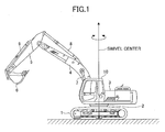
- FIG. 1 is a side view of the shovel of the embodiment.
- the shovel illustrated in FIG. 1 is a hybrid-type shovel.
- the present invention is not limited to the hybrid-type shovel and is applicable to any type of shovel as long as an electrical power storage device is provided as a driving power source for driving an electrical load.
- an upper-part swiveling body 3 is installed in a lower-part traveling body 1 of the hybrid-type shovel through a swivel mechanism 2.
- the upper-part swiveling body 3 includes a boom 4, an arm 5, a bucket 6, a boom cylinder 7 for hydraulically driving the boom 4, an arm cylinder 8 for hydraulically driving the arm 5, and a bucket cylinder 9 for hydraulically driving the bucket 6.
- a cabin 10 and a power source are mounted on the upper-part swiveling body 3.
- FIG. 2 is a block diagram illustrating a drive system of the working machine illustrated in FIG. 1 .
- a mechanical power system is indicated by a double line
- a high-pressure hydraulic line is indicated by a solid line
- a pilot line is indicated by a broken line
- an electrical drive and control system is indicated by a dot chain line.
- An engine 11 as a mechanical drive part and a motor generator 12 as an assist drive part are both connected to an input shaft of a transmission 13.
- a main pump 14 and a pilot pump 15 are connected to an output shaft of the transmission 13.
- a control valve 17 is connected to the main pump 14 through a high-pressure hydraulic line 16.
- the control valve 17 is a hydraulic control device that controls a hydraulic system. Hydraulic motors 1A (for the right) and 1B (for the left) for the lower-part traveling body 1, the boom cylinder 7, the arm cylinder 8, and the bucket cylinder 9 are connected to the control valve 17 through the high-pressure hydraulic line 16.
- An electrical power storage apparatus 120 including a capacitor unit for electrical power storage or a battery is connected to the motor generator 12 through an inverter 18.
- the electrical power storage apparatus 120 includes a capacitor unit 19 as an electrical power storage device, for example, a lithium ion capacitor (LIC) or electric double layer capacitor (EDLC) as an electrical power storage device.
- a swivel motor 21 is connected to the electrical power storage apparatus 120 through the invertor 20.
- the capacitor unit 19 is exemplified above as the electrical power storage device.
- a chargeable secondary battery such as a lithium ion battery (LIB) or another mode of a power source capable of exchanging the electrical power may be used instead of the capacitor unit 19.
- LIB lithium ion battery
- a resolver 22, a mechanical brake 23, and a swivel reduction transmission 24 are connected to a rotation shaft 21A of the swivel motor 21.
- An operation device 26 is connected to the pilot pump 15 through a pilot line 25.
- the control valve 17 and a pressure sensor 29 as a lever operation detection part are connected to the operation device 26 through hydraulic lines 27 and 28, respectively.
- the pressure sensor 29 is connected to a controller 30 that controls to drive an electrical system.
- the inverter 18, which is provided between the motor generator 12 and the electrical power storage apparatus 120 as described above, controls the operation of the motor generator 12 based on a command sent from the controller 30. Therefore, while the inverter 18 performs a drive control of power running of the motor generator 12, the inverter 18 supplies necessary electrical power to the motor generator 12 from the electrical power storage apparatus 120. While regeneration of the motor generator 12 is subjected to a drive control, electrical power generated by the motor generator 12 is stored in the capacitor unit 19 of the electrical power storage apparatus 120.
- the electrical power storage apparatus 120 is arranged between the inverter 18 and the inverter 20. With this, while at least one of the motor generator 12 and the swivel motor 21 performs a power running operation, the electrical power storage apparatus 120 supplies electrical power necessary for the power running. While at least one of the motor generator 12 and the swivel motor 21 performs a regeneration operation, the electrical power storage apparatus 120 stores regeneration electrical power generated by the regeneration operation.
- the inverter 20 is provided between the swivel motor 21 and the electrical power storage apparatus 120 as described above, controls the operation of the swivel motor 21 based on a command sent from the controller 30. Therefore, while the inverter 18 controls the power running of the swivel motor 21, the inverter 18 supplies necessary electrical power to the swivel motor 21 from the electrical power storage apparatus 120. While the swivel motor 21 performs the regeneration operation, the electrical power generated by the swivel motor 21 is stored in the capacitor unit 19 of the electrical power storage apparatus 120.
- a charge and discharge control for controlling the capacitor unit 19 of the electrical power storage apparatus 120 are performed by the controller 30 based on a charging condition of the capacitor unit 19, an operational condition of the motor generator 12 (the power running operation or the regeneration operation), and an operational condition of the swivel motor 21 (the power running operation or the regeneration operation).
- the controller 30 is a control device for performing a drive control of the shovel.
- the controller 30 includes a drive control apparatus 32, an electrical swivel control device 40, and a main control part 60.
- the controller 30 is made of an arithmetic processing unit including a central processing unit (CPU) and an internal memory.
- the drive control apparatus 32, the electrical swivel control device 40, and the main control part 60 are implemented by the CPU of the controller 30 when a program for the drive control stored in the internal memory is run.
- the arithmetic processing unit (not illustrated) converts a signal input from the pressure sensor 29 to a speed command.
- the operation amount of the lever 26A is converted to a speed command (rad/s) for rotating the swivel motor 21.
- This speed command is inputted into the drive control apparatus 32, the electrical swivel control device 40, and the main control part 60.
- the drive control apparatus 32 is a control apparatus for performing an operational control to control the motor generator 12 (a switchover between the power running operation and the regeneration operation) and a charge and discharge control of the capacitor unit 19.
- the drive control apparatus 32 switches between the power running operation and the regeneration operation depending on a state of a load of the engine 11 and the charging condition of the capacitor unit 19.
- the drive control apparatus 32 switches between the power running operation and the regeneration operation of the motor generator 12 so as to perform a charge and discharge control of the capacitor through the inverter 18.
- FIG. 3 is a circuit diagram of the electrical power storage apparatus 120.
- the electrical power storage apparatus 120 includes the capacitor unit 19 as the electrical power storage device, a buck-boost converter 100, and a DC bus 110.
- the DC bus 110 controls exchanges of electrical power among the capacitor unit 19, the motor generator 12, and the swivel motor 21.
- the capacitor unit 19 includes a capacitor voltage detection part 112 for detecting a capacitor voltage value and a capacitor current detection part 113 for detecting a capacitor current value.
- the capacitor voltage value and the capacitor current value which are detected by the capacitor voltage detection part 112 and the capacitor current detection part 113, respectively, are supplied to the controller 30.
- the buck-boost converter 100 switches between a boosting operation and a bucking operation so that a DC bus voltage value is within a predetermined range depending on the operational condition of the motor generator 12 and the swivel motor 21.
- the DC bus 110 is arranged among the inverter 18, the inverter 20, and the buck-boost converter 100 so as to give or receive the electrical power among the capacitor unit 19, the motor generator 12, and the swivel motor 21.
- a switchover control'between the boosting operation and the bucking operation in the buck-boost converter 100 is performed based on the DC bus voltage value detected by the DC bus voltage detection part 111, the capacitor voltage value detected by the capacitor voltage detection part 112, and the capacitor current value detected by the capacitor current detection part 113.
- the electrical power generated by the motor generator 12 being an assist motor is supplied to the DC bus 110 of the electrical power storage apparatus 120 through the inverter 18A and supplied to the capacitor unit 19 through the buck-boost converter 100.
- the regenerative electrical power generated by the swivel motor 21 is supplied to the DC bus 110 of an electrical power storage system 120 through the inverter 20 and supplied to the capacitor unit 19 through the buck-boost converter 100.
- the buck-boost converter 100 includes a reactor 101, a boost insulated gate bipolar transistor (IGBT) 102A for the boosting operation, a buck insulated gate bipolar transistor (IGBT) 102B for the bucking operation, power source connection terminals 104 for connecting the capacitor unit 19, output terminals 106 for connecting the inverters 105, and a smoothing capacitor 107 inserted in parallel to the pair of the output terminals 106.
- the DC bus 110 connects the output terminals 106 of the buck-boost converter 100 to the inverters 18 and 20.
- An end of the reactor 101 is connected to an intermediate point between the boost IGBT 102A and the buck IGBT 102B, and the other end of the reactor 101 is connected to the power source connection terminal 104.
- the reactor 101 is provided to supply an induced electromotive force generated when the boost IGBT 102A is turned on and off.
- the boost IGBT 102A and the buck IGBT 102B include a bipolar transistor having a gate in which a metal oxide semiconductor field effect transistor (MOSFET) is integrated.
- the boost IGBT 102A and the buck IGBT 102B are semiconductor elements (switching elements) which can perform high-power and high-speed switching.
- the boost IGBT 102A and the buck IGBT 102B are driven when a PWM voltage is applied to the gate terminals of the boost IGBT 102A and the buck IGBT 102B by the controller 30.
- Diodes 102a and 102b which are rectifying elements, are connected to the boost IGBT 102A and the buck IGBT 102B in parallel, respectively.
- the capacitor unit 19 may be an electrical power storage device, which can be charged and discharged so that the electrical power is exchanged between the capacitor unit 19 and the DC bus 110 through the buck-boost converter 100.
- the power source connection terminals 104 are terminals, to which the capacitor unit 19 is connectable, and the output terminals are terminals, to which the inverters 18 and 20 are connectable.
- the capacitor voltage detecting part 112 for detecting the capacitor voltage is connected between the pair of the power source connection terminals 104.
- the DC bus voltage detection part 111 for detecting the DC bus voltage is connected between the pair of output terminals 106.
- the capacitor voltage detection part 112 detects a voltage value Vcap of the capacitor unit 19.
- the DC bus voltage detection part 111 detects a voltage value Vdc of the DC bus 110.
- the smoothing capacitor 107 is an electrical power storage element for smoothing the DC bus voltage and inserted between a positive terminal and a negative terminal of the output terminals 106. The voltage of the DC bus 110 is maintained to be a predetermined voltage by the smoothing capacitor 107.
- the capacitor current detection part 113 detects a value of a current flowing between the capacitor unit 19 and the buck-boost converter 100 on a side of the positive electrode (a P terminal) of the capacitor unit 19 and includes a resistor for detecting the current.
- the capacitor current detection part 113 detects a current value I1 flowing through the positive electrode of the capacitor unit 19.
- the capacitor current detection part 116 detects a value of a current flowing between the capacitor unit 19 and the buck-boost converter 100 on a side of the negative electrode (a N terminal) of the capacitor unit 19 and includes a resistor for detecting the current.
- the capacitor current detection part 116 detects a current value I2 flowing through the negative electrode of the capacitor unit 19.
- the DC bus 110 When the DC bus 110 is boosted by the buck-boost converter 100, a PWM voltage is applied to the gate terminal of the boost IGBT 102A.
- the induced electromotive force is generated in the reactor 101 when the boost IGBT 102A is turned on or off, and is supplied to the DC bus 110 through the diode connected in parallel to the buck IGBT 102B.
- the voltage of the DC bus 110 is boosted up.
- a relay 130-1, 130-2 is provided as a shutoff switch for shutting off a power source line 114, which connects the positive terminal of the capacitor unit 19 to the power source connection terminal 104 of the buck-boost converter 100.
- the relay 130-1 is arranged between the positive terminal of the capacitor unit 19 and a connection point 115 of the capacitor voltage detection part 112 connected to the power source line 114.
- the relay 130-1 is operated by a signal from the controller 30. By shutting the power source line 114 from the capacitor unit 19 off, the capacitor unit 19 can be disconnected from the buck-boost converter 100.
- a relay 130-2 is provided as a shutoff switch for shutting off a power source line 117, which connects the negative terminal of the capacitor unit 19 to the power source connection terminal 104 of the buck-boost converter 100. Further, a relay 130-2 is arranged between the negative terminal of the capacitor unit 19 and a connection point 118 of the capacitor voltage detection part 112 connected to the power source line 117. The relay 130-2 is operated by a signal from the controller 30. By shutting the power source line 117 from the capacitor unit 19 off, the capacitor unit 19 can be disconnected from the buck-boost converter 100.
- the relay 130-1 and the relay 130-2 may be integrated as a single relay to enable simultaneously disconnecting both of the power source line 114 on the positive terminal side and the power source line 117 on the negative terminal side from the capacitor unit 19.
- the drive part for generating the PWM signal for driving the boost IGBT 102A and the buck IGBT 102B between the controller 30 and the boost IGBT and the buck IGBT 102A and 102B.
- the drive part is omitted from the illustration in FIG. 3 .
- This drive part may be substantialized by any one of an electronic circuit or an arithmetic processing unit.
- FIG. 4 is a schematic view illustrating a structure of the capacitor unit 19.
- the capacitor unit 19 as the electrical power storage device practically includes n capacitor cells (hereinafter, referred to as an electrical power storage cell or simply a cell) 19-1 to 19-n (n is an integer equal to 2 or greater) and an electrical power storage administration part 140.
- an electrical drive system is indicated by a solid line
- a control system is indicated by a broken line.
- the electrical power storage administration part 140 is provided to administrate power storage of the capacitor unit 19 and mainly includes an equalizing circuit part 141, an equalizing control part 142, and a voltage conversion part 143.
- the electrical power storage administration part 140 has an electrostatic capacitance measuring function of measuring the electrical capacities of the cells, an equalizing function of equalizing the electrical capacities of the cells, a circuit protecting function of preventing over discharge of the cells.
- all the n cells 19-1 to 19-n are connected in series and one electrical power storage administration part 140 is provided for all the cells.
- it may be structured such that cells connected in series are defined as a single group, multiple groups are connected in series or parallel, and a single electrical power storage administration part is provided for each group.
- another electrical power storage administration part may be provided to control the multiple electrical power storage administration parts as a superior authority.
- all the cells 19-1 to 19-n may be collectively called a cell 19-n or the n-th cell may be called a cell 19-n.
- the equalizing circuit part 141 and composing elements of the equalizing circuit parts 141 such as a balancing switch 146, a circuit protecting switch 147, a discharging resistor 148, a voltage measurement part 149, and so on are called in a manner similar thereto.
- the equalizing circuit part 141 is an electrical circuit substantializing the electrostatic capacitance measuring function, the equalizing function, and the circuit protecting function.
- the equalizing circuit part 141 is directly controlled by the equalizing control part 142 to perform the electrostatic capacitance measuring function and the equalizing function, and is indirectly controlled through the voltage conversion part 143 to perform the circuit protecting function.
- the indirect control through the voltage conversion part 143 is effective to enhance independence of the circuit protecting function. For example, even if a problem occurs at a part of the equalizing control part 142 and the equalizing function is erroneously operated, it is effective to securely operate the circuit protecting function.
- each of the equalizing circuit parts 141-n is connected to both ends of the corresponding one cell 19-n.
- two electrodes of a specific cell 19-m are connected to the equalizing circuit part 141-m.
- the equalizing circuit part 141-m includes a balancing switch 146-m, a circuit protecting switch 147-m, and a discharging resistor 148-m.
- the equalizing circuit part 141-m the balancing switch 146-m, the circuit protecting switch 147-m, and the discharging resistor 148-m are connected in series between the two electrodes of the cell 19-m and connected in parallel to the two electrodes of the cell 19-m.
- the balancing switch 146-m, the circuit protecting switch 147-m, and the discharging resistor 148-m may be connected in any order as long as these are connected in series.
- the equalizing circuit part 141-m incudes a voltage measurement part 149-m for measuring the inter-electrode voltage of the cell 19-m.
- the balancing switch 146-n is provided to control the discharge of the cell 19-n for equalizing the inter-electrode voltage of the cell so as to cause the cell 19-n to discharge when the balancing switch 146-n is in an ON (conduction) state and to cause the cell 19-n to stop discharging when the balancing switch 146-n is in an OFF (shutoff) state.
- the balancing switch 146-n is made of a field effect transistor (FET) and is switched between the ON (conduction) state the OFF (shutoff) state in response to a balance control signal sent by the equalizing control part 142.
- FET field effect transistor
- the circuit protecting switch 147-n is a switch (a shutoff part) for preventing the overdischarge of the cell 19-n, and enables the discharge of the cell 19-n in an ON (conduction) state and prohibits the discharge in an OFF (shutoff) state.
- the circuit protecting switch 147-n is made of a field effect transistor (FET), and is switched between an ON (conduction) state and an OFF (shutoff) state in response to a voltage applied to the gate of the circuit protecting switch 147-n by the voltage conversion part 143.
- FET field effect transistor
- the equalizing control part 142 is provided to control the electrostatic capacitance measuring function, the equalizing function, and the circuit protecting function. Within the embodiment, the equalizing control part 142 controls the equalizing circuit part 141 and the voltage conversion part 143. Specifically, the equalizing control part 142 outputs a voltage detection command to an equalizing circuit part 141-n and acquires a voltage detection value from the equalizing circuit part 141-n. Further, the equalizing control part 142 outputs the balance control signal to the balancing switch 146-n so as to switch between the ON (conduction) state and the OFF (shutoff) state.
- the equalizing control part 142 outputs an operation signal of a circuit protection signal to the voltage conversion part 143 so as to control a voltage applied to the gate of the circuit protecting switch 147-n by the voltage conversion part 143.
- the equalizing control part 142 is operated by a voltage derived from the capacitor unit 19.
- the equalizing control part 142 may be operated by a voltage derived from an external battery such as a 24 V battery.
- the voltage conversion part 143 is provided to control the circuit protecting function.
- the voltage conversion part 143 controls a voltage applied to the gate of the circuit protecting'switch 147-n.
- the voltage conversion part 143 converts the power source voltage of the power source 150 to a voltage (hereinafter, referred to as an "ON voltage") causing the circuit protecting switch 147-n to be in the ON (conduction) state when an operation signal is received from the equalizing control part 142.
- the ON voltage is applied to the gate of the circuit protecting switch 147-n, the circuit protecting switch 147-n becomes in the ON (conduction) state.
- the voltage conversion part 143 converts the power source voltage of the power source 150 to a voltage (hereinafter, referred to as an "OFF voltage") causing the circuit protecting switch 147-n to be in the OFF (shutoff) state when a circuit protection signal is received from the equalizing control part 142.
- OFF voltage a voltage
- the power source voltage of the power source 150 may be a voltage derived from the capacitor unit 19 or an external battery such as a 24 V battery. Further, as long as the voltage conversion part 143 is in an operating state, the power source voltage of the power source 150 may be converted to the ON voltage and applied to the gate of the circuit protecting switch 147-n regardless of whether the operation signal is received or not.
- the electrical power storage administration part 140 having the above structure can individually measure the electrostatic capacitance of the cells 19-n by the electrostatic capacitance measuring function.
- the equalizing control part 142 includes an electrostatic capacitance calculation part (not illustrated) for calculating the electrical capacities based on the voltages of the cells 19-n measured by the voltage measurement part 149-n.
- the voltage detection command detects the inter-electrode voltages (hereinafter, the inter-electrode voltage is referred to as a cell voltage Vn) of the cells 19-n and sends the detected cell voltages of the cells 19-n to the electrostatic capacitance calculation part.
- the inter-electrode voltage is referred to as a cell voltage Vn
- the electrostatic capacitance calculation part calculates the electrical capacities Cn of the cells 19-n based on the value of the cell voltages Vn of the cells 19-n sent from the voltage measurement part 149-n.
- the electrostatic capacitance Cn is calculated as follows.
- the cell voltage Vn0 of the cell 19-n subjected to the calculation of the electrostatic capacitance at a time of starting to calculate the electrostatic capacitance Cn. Then, the balance control signal is sent to the gate of the balancing FET 146-n as the balancing switch to close the balancing FET 146-n to be in the ON (conduction) state. Thus, the cell is short-circuited and electricity is discharged from the cell 19-n. Because the discharging resistor 148-n is provided in a short-circuiting line, a discharge current discharged from the cell 19-n is a very small electrical current. Therefore, the cell voltage Vn of the cell 19-n does not suddenly decrease but gradually decreases.
- R1 designates an internal resistance of the cell 19-n
- R2 designates an internal resistance of the discharging resistor 148-n.
- R1 can be ignored because R1 ⁇ R2.
- the following formula (2) can be introduced.
- Cn - T / R ⁇ 2 ⁇ ln - 1 Vn ⁇ 1 / Vn ⁇ 0
- the electrostatic capacitance becomes small and simultaneously the internal resistance increases.
- the cell voltages also become ununiform. Therefore, the voltages of the cells are partly high and partly low despite the application of the same current to the cells. As a result, the degraded cell is further degraded. Therefore, it is desirable to positively make the voltages of the cells uniform depending on the nonuniformity of degradation of the cells.
- the equalizing function of the electrical power storage administration part 140 determines degradation degrees of the cells 19-n based on the calculated electrostatic capacitance Cn at the present time. Then, the electrical power storage administration part 140 equalizes the cell voltages by causing only the cell, which requires the discharge depending on the degradation degree, to discharge electricity by the function of the equalizing circuit.
- the electrical power storage administration part 140 prevents the overdischarge of the cells 19-n by the circuit protecting function.
- FIG. 5 is a flowchart illustrating a flow of the circuit protection process.
- FIG. 6 illustrates a transition of the cell voltage when the circuit protection process is performed. In FIG.
- a transition of the cell voltage related to the balancing FET 146-1, which is in a defect state, is indicated by a solid line
- transitions of the cell voltage related to the balancing FET 146-2 and the balancing FET 146-3, which are in a normal state are indicated by a dot chain line and a two-dot chain line.
- the circuit protection process is performed in a state where a current is not input into or output from the capacitor unit 19, said differently, a charge and discharge current does not flow through the cells 19-n of the capacitor unit 19.
- the circuit protection process may be performed during the operation of the shovel in a state where there is no input of the current into the capacitor unit 19 and no output of the current from the capacitor unit 19.
- the electrical power storage administration part 140 determines whether there is a defect in the equalizing circuit part 141-n or not after the electrical power storage administration part 140 detects a charge and discharge stop state where there is no electrical current flowing between the capacitor unit 19 and the buck-boost converter 100 or actively making the charge and discharge stop state.
- the electrical power storage administration part 140 determines that there is a defect in the equalizing circuit part 141-n, the electrical power storage administration part 140 shuts off (breaks) connections between the equalizing circuit part 141-n and the two electrodes of the corresponding cell 19-n so as to prevent the overdischarge of the corresponding cell 19-n.
- step S1 of FIG. 5 the balance control signal is sent to the gates of the balancing FETs 146-n of all the cells 19-n to make the balancing FETs 146-n in the OFF (shutoff) state (see a time t0 of FIG. 6 ).
- step S2 the cell voltages of all the cells 19-n are checked (see a time t1 of FIG. 6 ). Subsequently, it is determined whether a check of the cell voltage is a first check in the circuit protection process at the present time in step S3. If the check of the cell voltage is a second check or later, the process goes to step S5. It is to prevent the cell voltage recorded at a time of starting the circuit protection process from being overwritten.
- step S3 If it is determined in step S3 that the detection of the cell voltage is the first check in the circuit protection process at the present time, the process goes to step S4.
- step S4 the cell voltages of all the cells 19-n are recorded as a cell voltage Vna-n.
- step S5 it is determined whether an elapsed time ⁇ Td after the balancing FET 146-n is in the OFF (shutoff) state is a predetermined time Td1 or longer. If the elapsed time ⁇ Td is shorter than the predetermined time Td1, it is determined that a condition enabling the detection of a malfunction such as the short circuit in the balancing FET 146-n or a fixture to the ON state in the balancing FET 146-n. Thus, the process returns to step S2 and a process on or after step S2 is performed again.
- step S6 the cell voltages of all the cells 19-n are recorded as the cell voltage Vnb-n (see a time t2 of FIG. 6 ). Specifically, the cell voltages of all the cells 19-n checked in the recent step S2 is recorded as the cell voltage Vnb-n.
- step S7 the equalizing control part 142 as an equalizing circuit defect determination part determines whether there is a defect in the equalizing circuit part 141-n. Specifically, it is determined that a difference Vdif-n between a cell voltage Vna-n at a time of starting the circuit protection process and a cell voltage Vnb-n after a passage of a predetermined time Td1 from the time of starting the circuit protection process is a predetermined voltage Va or greater.
- step S2 If it is determined that the difference Vdif-n between the cell voltage Vna-n and the cell voltage Vnb-n is not the predetermined voltage Va or greater, namely it is determined that the malfunction such as the short circuit or the fixture to the ON state in the balancing FET 146-n does not occur. Thus, it is determined that there is no defect in the equalizing circuit part 141-n, and the process returns to step S2 and a process on or after step S2 is performed again. This case corresponds to transitions of the cell voltages related to the balancing FET 146-2 and the balancing FET 146-3 in the normal state indicated by the dot chain line and the two-dot chain line of FIG. 6 .
- a difference Vdif-2 between the cell voltage Vna-2 and cell voltage Vnb-2 related to the balancing FET 146-2 and difference Vdif-3 between the cell voltage Vna-3 and cell voltage Vnb-3 related to the balancing FET 146-3 are smaller than the predetermined voltage Va and substantially zero.
- the difference Vdif-n between the cell voltage Vna-n and the cell voltage Vnb-n is the predetermined voltage Va or greater, it is determined that the malfunction such as the short circuit or the fixture to the ON state in the balancing FET 146-noccurs.
- the process goes to step S8. This is because it is possible to determine that the cell 19-n discharges electricity because the cell voltage drops even though the balancing FET 146-n is in the OFF (shutoff) state. This case corresponds to a transition of the cell voltage related to the balancing FET 146-1 in a defect state indicated by the solid line in FIG. 6 .
- the difference Vdif-1 between the cell voltage Vna-1 and the cell voltage Vnb-1 related to the balancing FET 146-1 is greater than the predetermined voltage Va.
- step S8 the circuit protection signal is output to the voltage conversion part 143.
- the voltage conversion part 143 receiving the circuit protection signal applies an OFF voltage to the gate of the circuit protecting switch 147-n corresponding to the balancing FET 146-n causing the malfunction such as the short circuit or the fixture to the ON state in the balancing switch 146-n.
- the circuit protecting switch 147-n corresponding to the balancing FET 146-n causing the malfunction such as the short circuit or the fixture to the ON state in the balancing switch 146-n becomes in the OFF (shutoff) state so as to prohibit discharge of the cell 19-n corresponding to the balancing FET 146-n causing the malfunction such as the short circuit or the fixture to the ON state in the balancing switch 146-n (see a time t3 of FIG. 6 ).
- This case corresponds to the transition of the cell voltage related to the balancing FET 146-1 in the defect state indicated by the solid line in FIG. 6 .
- a decrease of the cell voltage related to the balancing FET 146-1 is stopped as a result of the prohibition of the discharge of the cell 19-1 at the time t3.
- the electrical power storage administration part 140 causes the circuit protecting switch 147-n corresponding to the balancing FET 146-n causing the malfunction such as the short circuit or the fixture to the ON state in the balancing switch 146-n to be in the OFF (shutoff) state so as to prevent the over discharge of the cell 19-n.
- FIG. 7 is a schematic view of the structure of the capacitor unit 19 and corresponds to FIG. 4 . Therefore, the same reference symbols are attached to commonly used composing elements, and description thereof is omitted.
- the electrical power storage administration part 140A differs from the electrical power storage administration part 140 at a point that the voltage conversion part is omitted. Specifically, the equalizing control part 142 of the electrical power storage administration part 140A does not indirectly switch between the ON (conduction) state and the OFF (shutoff) state of the circuit protecting switch 147-n through the voltage conversion part but directly switches between the states of the circuit protecting switch 147-n.
- the circuit protection signal is output to the circuit protecting switch 147-n corresponding to the balancing switch 146-n causing the malfunction.
- the equalizing control part 142 sends the circuit protection signal to the gate of the circuit protection FET 147-n as the circuit protecting switch to make the circuit protection FET 147-n in the OFF (shutoff) state.
- the ON voltage is applied to the circuit protection FET 147-n to cause the circuit protection FET 147-n to be in the ON (conduction) state.
- the circuit protection FET 147-n may be operated by the same power source as that for the balancing FET 146-n as the balancing switch or may be operated by a power source different from the power source for the balancing FET 146-n.
- the circuit protection FET 147-n may be operated by a voltage derived from the capacitor unit 19 or a voltage derived from an external battery such as a 24 V battery.
Landscapes
- Engineering & Computer Science (AREA)
- Power Engineering (AREA)
- Mechanical Engineering (AREA)
- Sustainable Energy (AREA)
- Life Sciences & Earth Sciences (AREA)
- Transportation (AREA)
- Sustainable Development (AREA)
- Mining & Mineral Resources (AREA)
- Civil Engineering (AREA)
- General Engineering & Computer Science (AREA)
- Structural Engineering (AREA)
- Charge And Discharge Circuits For Batteries Or The Like (AREA)
- Secondary Cells (AREA)
- Operation Control Of Excavators (AREA)
Abstract
Description
- The present invention relates to a shovel including an electrical power storage device formed by multiple electrical power storage cells for charging electricity generated by a generator and multiple equalizing circuits respectively connected to multiple electrical power storage cells and a method of controlling the shovel.
- There is a capacitor unit including multiple electrical double layer capacitors (cells) connected in series and balance circuits (equalizing circuits) respectively provided for the cells (for example, Patent Document 1).
- PATENT DOCUMENT 1: Japanese Unexamined Patent Publication No.
2010-213417 - In a capacitor unit including a great number of cells, if the cells are degraded, nonuniformity occurs among the electric capacities of the cells. When charging and discharging are repeated while the nonuniformity occurs among the electric capacities of the cells, a load to the cell having a high degree of the degradation further increases. Thus, the nonuniformity becomes more conspicuous and the electrostatic capacitance of the cell having a high degree of the degradation further decreases. As a result, there occurs a problem that the electrostatic capacitance (i.e., an electrical power storage quantity) of the entire capacitor unit, which is the sum of the electric capacities of the multiple cells, decreases and the internal resistance increases.
- For this, the equalizing circuit disclosed in
Patent Document 1 performs equalization to the cell having a predetermined inter-electrode voltage value or greater at a certain time point. Said differently, the cell having the predetermined inter-electrode voltage value or greater is forcibly discharged to make the inter-electrode voltage a predetermined value so as to equalize the inter-electrode voltages among the multiple cells. - However, when the equalizing circuit short-circuits, the cell corresponding to the equalizing circuit may become in an over discharged state so as to give a bad influence to the capacitor unit.
- Therefore, in a case where there occurs a defect in the equalizing circuit, it is desired to prevent the cell corresponding to the equalizing circuit from being in the over discharged state.
- A shovel of an embodiment of the present invention includes an electrical power storage device that is made of a plurality of electrical power storage cells for charging electricity generated by a generator; equalizing circuits each of which is connected to corresponding one of the plurality of electrical power storage cells and includes a balancing switch and a circuit protecting switch; and an equalizing control part that outputs a balance control signal for switching between shutoff or conduction of the balancing switch and a circuit protection signal for shutting off the circuit protecting switch.
- Further, a method of controlling a shovel of the embodiment of the present invention includes an electrical power storage device that is made of a plurality of electrical power storage cells for charging electricity generated by a generator, and equalizing circuits each of which is connected to corresponding one of the plurality of electrical power storage cells and includes a balancing switch and a circuit protecting switch, the method including steps of outputting a balance control signal for switching shutoff or conduction of the balancing switch, and outputting a circuit protection signal for shutting off the circuit protecting switch.
- With the above means, there is provided a shovel that prevents the cell corresponding to the equalizing circuit causing the defect from being in the over discharged state and a method of controlling the shovel.
-
-
FIG. 1 is a side view of a hybrid-type shovel. -
FIG. 2 is a block diagram illustrating a structure of a drive system of the hybrid-type shovel of an embodiment of the present invention. -
FIG. 3 is a circuit diagram of an electrical power storage apparatus. -
FIG. 4 is a schematic view illustrating a structure of a capacitor unit. -
FIG. 5 is a flow chart illustrating a flow of a circuit protection process. -
FIG. 6 illustrates a transition of a cell voltage. -
FIG. 7 is a schematic view illustrating a structure of the capacitor unit. - An embodiment of the present invention is described with reference to figures.
-
FIG. 1 is a side view of the shovel of the embodiment. The shovel illustrated inFIG. 1 is a hybrid-type shovel. However, the present invention is not limited to the hybrid-type shovel and is applicable to any type of shovel as long as an electrical power storage device is provided as a driving power source for driving an electrical load. - Referring to
FIG. 1 , an upper-partswiveling body 3 is installed in a lower-part travelingbody 1 of the hybrid-type shovel through aswivel mechanism 2. The upper-partswiveling body 3 includes aboom 4, anarm 5, abucket 6, aboom cylinder 7 for hydraulically driving theboom 4, anarm cylinder 8 for hydraulically driving thearm 5, and abucket cylinder 9 for hydraulically driving thebucket 6. Further, acabin 10 and a power source are mounted on the upper-part swivelingbody 3. -
FIG. 2 is a block diagram illustrating a drive system of the working machine illustrated inFIG. 1 . Referring toFIG. 2 , a mechanical power system is indicated by a double line, a high-pressure hydraulic line is indicated by a solid line, a pilot line is indicated by a broken line, and an electrical drive and control system is indicated by a dot chain line. - An
engine 11 as a mechanical drive part and amotor generator 12 as an assist drive part are both connected to an input shaft of atransmission 13. Amain pump 14 and apilot pump 15 are connected to an output shaft of thetransmission 13. Acontrol valve 17 is connected to themain pump 14 through a high-pressurehydraulic line 16. - The
control valve 17 is a hydraulic control device that controls a hydraulic system.Hydraulic motors 1A (for the right) and 1B (for the left) for the lower-part travelingbody 1, theboom cylinder 7, thearm cylinder 8, and thebucket cylinder 9 are connected to thecontrol valve 17 through the high-pressurehydraulic line 16. - An electrical
power storage apparatus 120 including a capacitor unit for electrical power storage or a battery is connected to themotor generator 12 through aninverter 18. Within this embodiment, the electricalpower storage apparatus 120 includes acapacitor unit 19 as an electrical power storage device, for example, a lithium ion capacitor (LIC) or electric double layer capacitor (EDLC) as an electrical power storage device. Aswivel motor 21 is connected to the electricalpower storage apparatus 120 through theinvertor 20. Thecapacitor unit 19 is exemplified above as the electrical power storage device. However, a chargeable secondary battery such as a lithium ion battery (LIB) or another mode of a power source capable of exchanging the electrical power may be used instead of thecapacitor unit 19. - A
resolver 22, amechanical brake 23, and aswivel reduction transmission 24 are connected to arotation shaft 21A of theswivel motor 21. Anoperation device 26 is connected to thepilot pump 15 through apilot line 25. - The
control valve 17 and apressure sensor 29 as a lever operation detection part are connected to theoperation device 26 throughhydraulic lines pressure sensor 29 is connected to acontroller 30 that controls to drive an electrical system. - The
inverter 18, which is provided between themotor generator 12 and the electricalpower storage apparatus 120 as described above, controls the operation of themotor generator 12 based on a command sent from thecontroller 30. Therefore, while theinverter 18 performs a drive control of power running of themotor generator 12, theinverter 18 supplies necessary electrical power to themotor generator 12 from the electricalpower storage apparatus 120. While regeneration of themotor generator 12 is subjected to a drive control, electrical power generated by themotor generator 12 is stored in thecapacitor unit 19 of the electricalpower storage apparatus 120. - The electrical
power storage apparatus 120 is arranged between theinverter 18 and theinverter 20. With this, while at least one of themotor generator 12 and theswivel motor 21 performs a power running operation, the electricalpower storage apparatus 120 supplies electrical power necessary for the power running. While at least one of themotor generator 12 and theswivel motor 21 performs a regeneration operation, the electricalpower storage apparatus 120 stores regeneration electrical power generated by the regeneration operation. - The
inverter 20 is provided between theswivel motor 21 and the electricalpower storage apparatus 120 as described above, controls the operation of theswivel motor 21 based on a command sent from thecontroller 30. Therefore, while theinverter 18 controls the power running of theswivel motor 21, theinverter 18 supplies necessary electrical power to theswivel motor 21 from the electricalpower storage apparatus 120. While theswivel motor 21 performs the regeneration operation, the electrical power generated by theswivel motor 21 is stored in thecapacitor unit 19 of the electricalpower storage apparatus 120. - A charge and discharge control for controlling the
capacitor unit 19 of the electricalpower storage apparatus 120 are performed by thecontroller 30 based on a charging condition of thecapacitor unit 19, an operational condition of the motor generator 12 (the power running operation or the regeneration operation), and an operational condition of the swivel motor 21 (the power running operation or the regeneration operation). - The
controller 30 is a control device for performing a drive control of the shovel. Thecontroller 30 includes adrive control apparatus 32, an electricalswivel control device 40, and amain control part 60. Thecontroller 30 is made of an arithmetic processing unit including a central processing unit (CPU) and an internal memory. Thedrive control apparatus 32, the electricalswivel control device 40, and themain control part 60 are implemented by the CPU of thecontroller 30 when a program for the drive control stored in the internal memory is run. - The arithmetic processing unit (not illustrated) converts a signal input from the
pressure sensor 29 to a speed command. The operation amount of thelever 26A is converted to a speed command (rad/s) for rotating theswivel motor 21. This speed command is inputted into thedrive control apparatus 32, the electricalswivel control device 40, and themain control part 60. - The
drive control apparatus 32 is a control apparatus for performing an operational control to control the motor generator 12 (a switchover between the power running operation and the regeneration operation) and a charge and discharge control of thecapacitor unit 19. Thedrive control apparatus 32 switches between the power running operation and the regeneration operation depending on a state of a load of theengine 11 and the charging condition of thecapacitor unit 19. Thedrive control apparatus 32 switches between the power running operation and the regeneration operation of themotor generator 12 so as to perform a charge and discharge control of the capacitor through theinverter 18. -
FIG. 3 is a circuit diagram of the electricalpower storage apparatus 120. The electricalpower storage apparatus 120 includes thecapacitor unit 19 as the electrical power storage device, a buck-boost converter 100, and aDC bus 110. TheDC bus 110 controls exchanges of electrical power among thecapacitor unit 19, themotor generator 12, and theswivel motor 21. Thecapacitor unit 19 includes a capacitorvoltage detection part 112 for detecting a capacitor voltage value and a capacitorcurrent detection part 113 for detecting a capacitor current value. The capacitor voltage value and the capacitor current value, which are detected by the capacitorvoltage detection part 112 and the capacitorcurrent detection part 113, respectively, are supplied to thecontroller 30. - The buck-
boost converter 100 switches between a boosting operation and a bucking operation so that a DC bus voltage value is within a predetermined range depending on the operational condition of themotor generator 12 and theswivel motor 21. TheDC bus 110 is arranged among theinverter 18, theinverter 20, and the buck-boost converter 100 so as to give or receive the electrical power among thecapacitor unit 19, themotor generator 12, and theswivel motor 21. - A switchover control'between the boosting operation and the bucking operation in the buck-
boost converter 100 is performed based on the DC bus voltage value detected by the DC busvoltage detection part 111, the capacitor voltage value detected by the capacitorvoltage detection part 112, and the capacitor current value detected by the capacitorcurrent detection part 113. - In the above described structure, the electrical power generated by the
motor generator 12 being an assist motor is supplied to theDC bus 110 of the electricalpower storage apparatus 120 through the inverter 18A and supplied to thecapacitor unit 19 through the buck-boost converter 100. The regenerative electrical power generated by theswivel motor 21 is supplied to theDC bus 110 of an electricalpower storage system 120 through theinverter 20 and supplied to thecapacitor unit 19 through the buck-boost converter 100. - The buck-
boost converter 100 includes areactor 101, a boost insulated gate bipolar transistor (IGBT) 102A for the boosting operation, a buck insulated gate bipolar transistor (IGBT) 102B for the bucking operation, powersource connection terminals 104 for connecting thecapacitor unit 19,output terminals 106 for connecting the inverters 105, and a smoothingcapacitor 107 inserted in parallel to the pair of theoutput terminals 106. TheDC bus 110 connects theoutput terminals 106 of the buck-boost converter 100 to theinverters - An end of the
reactor 101 is connected to an intermediate point between theboost IGBT 102A and thebuck IGBT 102B, and the other end of thereactor 101 is connected to the powersource connection terminal 104. Thereactor 101 is provided to supply an induced electromotive force generated when theboost IGBT 102A is turned on and off. - The
boost IGBT 102A and thebuck IGBT 102B include a bipolar transistor having a gate in which a metal oxide semiconductor field effect transistor (MOSFET) is integrated. Theboost IGBT 102A and thebuck IGBT 102B are semiconductor elements (switching elements) which can perform high-power and high-speed switching. Theboost IGBT 102A and thebuck IGBT 102B are driven when a PWM voltage is applied to the gate terminals of theboost IGBT 102A and thebuck IGBT 102B by thecontroller 30.Diodes boost IGBT 102A and thebuck IGBT 102B in parallel, respectively. - The
capacitor unit 19 may be an electrical power storage device, which can be charged and discharged so that the electrical power is exchanged between thecapacitor unit 19 and theDC bus 110 through the buck-boost converter 100. - It is sufficient that the power
source connection terminals 104 are terminals, to which thecapacitor unit 19 is connectable, and the output terminals are terminals, to which theinverters voltage detecting part 112 for detecting the capacitor voltage is connected between the pair of the powersource connection terminals 104. The DC busvoltage detection part 111 for detecting the DC bus voltage is connected between the pair ofoutput terminals 106. - The capacitor
voltage detection part 112 detects a voltage value Vcap of thecapacitor unit 19. The DC busvoltage detection part 111 detects a voltage value Vdc of theDC bus 110. The smoothingcapacitor 107 is an electrical power storage element for smoothing the DC bus voltage and inserted between a positive terminal and a negative terminal of theoutput terminals 106. The voltage of theDC bus 110 is maintained to be a predetermined voltage by the smoothingcapacitor 107. - The capacitor
current detection part 113 detects a value of a current flowing between thecapacitor unit 19 and the buck-boost converter 100 on a side of the positive electrode (a P terminal) of thecapacitor unit 19 and includes a resistor for detecting the current. The capacitorcurrent detection part 113 detects a current value I1 flowing through the positive electrode of thecapacitor unit 19. The capacitorcurrent detection part 116 detects a value of a current flowing between thecapacitor unit 19 and the buck-boost converter 100 on a side of the negative electrode (a N terminal) of thecapacitor unit 19 and includes a resistor for detecting the current. The capacitorcurrent detection part 116 detects a current value I2 flowing through the negative electrode of thecapacitor unit 19. - When the
DC bus 110 is boosted by the buck-boost converter 100, a PWM voltage is applied to the gate terminal of theboost IGBT 102A. The induced electromotive force is generated in thereactor 101 when theboost IGBT 102A is turned on or off, and is supplied to theDC bus 110 through the diode connected in parallel to thebuck IGBT 102B. Thus, the voltage of theDC bus 110 is boosted up. - When the
DC bus 110 is bucked, a PWM voltage is applied to the gate terminal of thebuck IGBT 102B. The regenerative electrical power supplied through thebuck IGBT 102B and theinverters capacitor unit 19 from theDC bus 110. Then, the electrical power stored in theDC bus 110 is charged into thecapacitor unit 19 and theDC bus 110 is bucked. - Within this embodiment, a relay 130-1, 130-2 is provided as a shutoff switch for shutting off a
power source line 114, which connects the positive terminal of thecapacitor unit 19 to the powersource connection terminal 104 of the buck-boost converter 100. The relay 130-1 is arranged between the positive terminal of thecapacitor unit 19 and aconnection point 115 of the capacitorvoltage detection part 112 connected to thepower source line 114. The relay 130-1 is operated by a signal from thecontroller 30. By shutting thepower source line 114 from thecapacitor unit 19 off, thecapacitor unit 19 can be disconnected from the buck-boost converter 100. - Further, a relay 130-2 is provided as a shutoff switch for shutting off a
power source line 117, which connects the negative terminal of thecapacitor unit 19 to the powersource connection terminal 104 of the buck-boost converter 100. Further, a relay 130-2 is arranged between the negative terminal of thecapacitor unit 19 and aconnection point 118 of the capacitorvoltage detection part 112 connected to thepower source line 117. The relay 130-2 is operated by a signal from thecontroller 30. By shutting thepower source line 117 from thecapacitor unit 19 off, thecapacitor unit 19 can be disconnected from the buck-boost converter 100. The relay 130-1 and the relay 130-2 may be integrated as a single relay to enable simultaneously disconnecting both of thepower source line 114 on the positive terminal side and thepower source line 117 on the negative terminal side from thecapacitor unit 19. - Practically, there is a drive part for generating the PWM signal for driving the
boost IGBT 102A and thebuck IGBT 102B between thecontroller 30 and the boost IGBT and thebuck IGBT FIG. 3 . This drive part may be substantialized by any one of an electronic circuit or an arithmetic processing unit. -
FIG. 4 is a schematic view illustrating a structure of thecapacitor unit 19. Referring toFIG. 4 , thecapacitor unit 19 as the electrical power storage device practically includes n capacitor cells (hereinafter, referred to as an electrical power storage cell or simply a cell) 19-1 to 19-n (n is an integer equal to 2 or greater) and an electrical powerstorage administration part 140. Referring toFIG. 4 , an electrical drive system is indicated by a solid line, a control system is indicated by a broken line. - The electrical power
storage administration part 140 is provided to administrate power storage of thecapacitor unit 19 and mainly includes an equalizingcircuit part 141, an equalizingcontrol part 142, and avoltage conversion part 143. - The electrical power
storage administration part 140 has an electrostatic capacitance measuring function of measuring the electrical capacities of the cells, an equalizing function of equalizing the electrical capacities of the cells, a circuit protecting function of preventing over discharge of the cells. Within this embodiment, for the convenience of explanation, all the n cells 19-1 to 19-n are connected in series and one electrical powerstorage administration part 140 is provided for all the cells. However, it may be structured such that cells connected in series are defined as a single group, multiple groups are connected in series or parallel, and a single electrical power storage administration part is provided for each group. Further, another electrical power storage administration part may be provided to control the multiple electrical power storage administration parts as a superior authority. - Hereinafter, all the cells 19-1 to 19-n may be collectively called a cell 19-n or the n-th cell may be called a cell 19-n. The equalizing
circuit part 141 and composing elements of the equalizingcircuit parts 141 such as a balancingswitch 146, acircuit protecting switch 147, a dischargingresistor 148, avoltage measurement part 149, and so on are called in a manner similar thereto. - The equalizing
circuit part 141 is an electrical circuit substantializing the electrostatic capacitance measuring function, the equalizing function, and the circuit protecting function. Within the embodiment,'the equalizingcircuit part 141 is directly controlled by the equalizingcontrol part 142 to perform the electrostatic capacitance measuring function and the equalizing function, and is indirectly controlled through thevoltage conversion part 143 to perform the circuit protecting function. The indirect control through thevoltage conversion part 143 is effective to enhance independence of the circuit protecting function. For example, even if a problem occurs at a part of the equalizingcontrol part 142 and the equalizing function is erroneously operated, it is effective to securely operate the circuit protecting function. - Specifically, each of the equalizing circuit parts 141-n is connected to both ends of the corresponding one cell 19-n. For example, as illustrated in
FIG. 4 , two electrodes of a specific cell 19-m (m is an integer of one or greater and n or smaller) are connected to the equalizing circuit part 141-m. Further, the equalizing circuit part 141-m includes a balancing switch 146-m, a circuit protecting switch 147-m, and a discharging resistor 148-m. Further, in the equalizing circuit part 141-m, the balancing switch 146-m, the circuit protecting switch 147-m, and the discharging resistor 148-m are connected in series between the two electrodes of the cell 19-m and connected in parallel to the two electrodes of the cell 19-m. The balancing switch 146-m, the circuit protecting switch 147-m, and the discharging resistor 148-m may be connected in any order as long as these are connected in series. Further, the equalizing circuit part 141-m incudes a voltage measurement part 149-m for measuring the inter-electrode voltage of the cell 19-m. - The balancing switch 146-n is provided to control the discharge of the cell 19-n for equalizing the inter-electrode voltage of the cell so as to cause the cell 19-n to discharge when the balancing switch 146-n is in an ON (conduction) state and to cause the cell 19-n to stop discharging when the balancing switch 146-n is in an OFF (shutoff) state. Within this embodiment, the balancing switch 146-n is made of a field effect transistor (FET) and is switched between the ON (conduction) state the OFF (shutoff) state in response to a balance control signal sent by the equalizing
control part 142. - The circuit protecting switch 147-n is a switch (a shutoff part) for preventing the overdischarge of the cell 19-n, and enables the discharge of the cell 19-n in an ON (conduction) state and prohibits the discharge in an OFF (shutoff) state. Within the embodiment, the circuit protecting switch 147-n is made of a field effect transistor (FET), and is switched between an ON (conduction) state and an OFF (shutoff) state in response to a voltage applied to the gate of the circuit protecting switch 147-n by the
voltage conversion part 143. - The equalizing
control part 142 is provided to control the electrostatic capacitance measuring function, the equalizing function, and the circuit protecting function. Within the embodiment, the equalizingcontrol part 142 controls the equalizingcircuit part 141 and thevoltage conversion part 143. Specifically, the equalizingcontrol part 142 outputs a voltage detection command to an equalizing circuit part 141-n and acquires a voltage detection value from the equalizing circuit part 141-n. Further, the equalizingcontrol part 142 outputs the balance control signal to the balancing switch 146-n so as to switch between the ON (conduction) state and the OFF (shutoff) state. Further, the equalizingcontrol part 142 outputs an operation signal of a circuit protection signal to thevoltage conversion part 143 so as to control a voltage applied to the gate of the circuit protecting switch 147-n by thevoltage conversion part 143. Within the embodiment, the equalizingcontrol part 142 is operated by a voltage derived from thecapacitor unit 19. However, the equalizingcontrol part 142 may be operated by a voltage derived from an external battery such as a 24 V battery. - The
voltage conversion part 143 is provided to control the circuit protecting function. Within the embodiment, thevoltage conversion part 143 controls a voltage applied to the gate of the circuit protecting'switch 147-n. Specifically, thevoltage conversion part 143 converts the power source voltage of thepower source 150 to a voltage (hereinafter, referred to as an "ON voltage") causing the circuit protecting switch 147-n to be in the ON (conduction) state when an operation signal is received from the equalizingcontrol part 142. When the ON voltage is applied to the gate of the circuit protecting switch 147-n, the circuit protecting switch 147-n becomes in the ON (conduction) state. Meanwhile, thevoltage conversion part 143 converts the power source voltage of thepower source 150 to a voltage (hereinafter, referred to as an "OFF voltage") causing the circuit protecting switch 147-n to be in the OFF (shutoff) state when a circuit protection signal is received from the equalizingcontrol part 142. When the OFF voltage is applied to the gate of the circuit protecting switch 147-n, the circuit protecting switch 147-n becomes in the OFF (shutoff) state. The power source voltage of thepower source 150 may be a voltage derived from thecapacitor unit 19 or an external battery such as a 24 V battery. Further, as long as thevoltage conversion part 143 is in an operating state, the power source voltage of thepower source 150 may be converted to the ON voltage and applied to the gate of the circuit protecting switch 147-n regardless of whether the operation signal is received or not. - The electrical power
storage administration part 140 having the above structure can individually measure the electrostatic capacitance of the cells 19-n by the electrostatic capacitance measuring function. - In order to substantialize the electrostatic capacitance measuring function, the equalizing
control part 142 includes an electrostatic capacitance calculation part (not illustrated) for calculating the electrical capacities based on the voltages of the cells 19-n measured by the voltage measurement part 149-n. - When a voltage detection command is given to the voltage measurement part 149-n, the voltage detection command detects the inter-electrode voltages (hereinafter, the inter-electrode voltage is referred to as a cell voltage Vn) of the cells 19-n and sends the detected cell voltages of the cells 19-n to the electrostatic capacitance calculation part.
- The electrostatic capacitance calculation part calculates the electrical capacities Cn of the cells 19-n based on the value of the cell voltages Vn of the cells 19-n sent from the voltage measurement part 149-n. The electrostatic capacitance Cn is calculated as follows.
- At first, the cell voltage Vn0 of the cell 19-n subjected to the calculation of the electrostatic capacitance at a time of starting to calculate the electrostatic capacitance Cn. Then, the balance control signal is sent to the gate of the balancing FET 146-n as the balancing switch to close the balancing FET 146-n to be in the ON (conduction) state. Thus, the cell is short-circuited and electricity is discharged from the cell 19-n. Because the discharging resistor 148-n is provided in a short-circuiting line, a discharge current discharged from the cell 19-n is a very small electrical current. Therefore, the cell voltage Vn of the cell 19-n does not suddenly decrease but gradually decreases. After discharging for a predetermined time T, the cell voltage Vn1 at that time is detected. The electrostatic capacitance Cn of the cell 19-n can be calculated using the following formula (1):

- Here, R1 designates an internal resistance of the cell 19-n, and R2 designates an internal resistance of the discharging resistor 148-n. However, R1 can be ignored because R1<<R2. Then, the following formula (2) can be introduced.

- By comparing the calculated electrostatic capacitance Cn of the cell 19-n with an initial electrostatic capacitance Cn (electrostatic capacitance before starting use of the cell 19-n) of the cell 19-n previously acquired, it is possible to determine a degree of degradation of the cell at the present time.
- When the degradation of the cell proceeds, the electrostatic capacitance becomes small and simultaneously the internal resistance increases. When the electrostatic capacitances and the internal resistances are not uniform between the cells, the cell voltages also become ununiform. Therefore, the voltages of the cells are partly high and partly low despite the application of the same current to the cells. As a result, the degraded cell is further degraded. Therefore, it is desirable to positively make the voltages of the cells uniform depending on the nonuniformity of degradation of the cells.
- Within the embodiment, the equalizing function of the electrical power
storage administration part 140 determines degradation degrees of the cells 19-n based on the calculated electrostatic capacitance Cn at the present time. Then, the electrical powerstorage administration part 140 equalizes the cell voltages by causing only the cell, which requires the discharge depending on the degradation degree, to discharge electricity by the function of the equalizing circuit. - Further, the electrical power
storage administration part 140 prevents the overdischarge of the cells 19-n by the circuit protecting function. Here, referring toFIGs. 5-6 , described is the circuit protection process of preventing the overdischarge of the cells 19-n.FIG. 5 is a flowchart illustrating a flow of the circuit protection process.FIG. 6 illustrates a transition of the cell voltage when the circuit protection process is performed. InFIG. 6 , a transition of the cell voltage related to the balancing FET 146-1, which is in a defect state, is indicated by a solid line, and transitions of the cell voltage related to the balancing FET 146-2 and the balancing FET 146-3, which are in a normal state, are indicated by a dot chain line and a two-dot chain line. - The circuit protection process is performed in a state where a current is not input into or output from the
capacitor unit 19, said differently, a charge and discharge current does not flow through the cells 19-n of thecapacitor unit 19. The circuit protection process may be performed during the operation of the shovel in a state where there is no input of the current into thecapacitor unit 19 and no output of the current from thecapacitor unit 19. Specifically, the electrical powerstorage administration part 140 determines whether there is a defect in the equalizing circuit part 141-n or not after the electrical powerstorage administration part 140 detects a charge and discharge stop state where there is no electrical current flowing between thecapacitor unit 19 and the buck-boost converter 100 or actively making the charge and discharge stop state. In a case where the electrical powerstorage administration part 140 determines that there is a defect in the equalizing circuit part 141-n, the electrical powerstorage administration part 140 shuts off (breaks) connections between the equalizing circuit part 141-n and the two electrodes of the corresponding cell 19-n so as to prevent the overdischarge of the corresponding cell 19-n. - In step S1 of
FIG. 5 , the balance control signal is sent to the gates of the balancing FETs 146-n of all the cells 19-n to make the balancing FETs 146-n in the OFF (shutoff) state (see a time t0 ofFIG. 6 ). - Subsequently, in step S2, the cell voltages of all the cells 19-n are checked (see a time t1 of
FIG. 6 ). Subsequently, it is determined whether a check of the cell voltage is a first check in the circuit protection process at the present time in step S3. If the check of the cell voltage is a second check or later, the process goes to step S5. It is to prevent the cell voltage recorded at a time of starting the circuit protection process from being overwritten. - If it is determined in step S3 that the detection of the cell voltage is the first check in the circuit protection process at the present time, the process goes to step S4. In step S4, the cell voltages of all the cells 19-n are recorded as a cell voltage Vna-n.
- Next, in step S5, it is determined whether an elapsed time ΔTd after the balancing FET 146-n is in the OFF (shutoff) state is a predetermined time Td1 or longer. If the elapsed time ΔTd is shorter than the predetermined time Td1, it is determined that a condition enabling the detection of a malfunction such as the short circuit in the balancing FET 146-n or a fixture to the ON state in the balancing FET 146-n. Thus, the process returns to step S2 and a process on or after step S2 is performed again.
- On the other hand, if the elapsed time ΔTd is the predetermined time Td1 is longer, the process goes to step S6. In step S6, the cell voltages of all the cells 19-n are recorded as the cell voltage Vnb-n (see a time t2 of
FIG. 6 ). Specifically, the cell voltages of all the cells 19-n checked in the recent step S2 is recorded as the cell voltage Vnb-n. - Next, in step S7, the equalizing
control part 142 as an equalizing circuit defect determination part determines whether there is a defect in the equalizing circuit part 141-n. Specifically, it is determined that a difference Vdif-n between a cell voltage Vna-n at a time of starting the circuit protection process and a cell voltage Vnb-n after a passage of a predetermined time Td1 from the time of starting the circuit protection process is a predetermined voltage Va or greater. If it is determined that the difference Vdif-n between the cell voltage Vna-n and the cell voltage Vnb-n is not the predetermined voltage Va or greater, namely it is determined that the malfunction such as the short circuit or the fixture to the ON state in the balancing FET 146-n does not occur. Thus, it is determined that there is no defect in the equalizing circuit part 141-n, and the process returns to step S2 and a process on or after step S2 is performed again. This case corresponds to transitions of the cell voltages related to the balancing FET 146-2 and the balancing FET 146-3 in the normal state indicated by the dot chain line and the two-dot chain line ofFIG. 6 . A difference Vdif-2 between the cell voltage Vna-2 and cell voltage Vnb-2 related to the balancing FET 146-2 and difference Vdif-3 between the cell voltage Vna-3 and cell voltage Vnb-3 related to the balancing FET 146-3 are smaller than the predetermined voltage Va and substantially zero. - If it is determined that the difference Vdif-n between the cell voltage Vna-n and the cell voltage Vnb-n is the predetermined voltage Va or greater, it is determined that the malfunction such as the short circuit or the fixture to the ON state in the balancing FET 146-noccurs. Thus, it is determined that there is a defect in the equalizing circuit part 141-n, and the process goes to step S8. This is because it is possible to determine that the cell 19-n discharges electricity because the cell voltage drops even though the balancing FET 146-n is in the OFF (shutoff) state. This case corresponds to a transition of the cell voltage related to the balancing FET 146-1 in a defect state indicated by the solid line in
FIG. 6 . The difference Vdif-1 between the cell voltage Vna-1 and the cell voltage Vnb-1 related to the balancing FET 146-1 is greater than the predetermined voltage Va. - In step S8, the circuit protection signal is output to the
voltage conversion part 143. Thevoltage conversion part 143 receiving the circuit protection signal applies an OFF voltage to the gate of the circuit protecting switch 147-n corresponding to the balancing FET 146-n causing the malfunction such as the short circuit or the fixture to the ON state in the balancing switch 146-n. As a result, the circuit protecting switch 147-n corresponding to the balancing FET 146-n causing the malfunction such as the short circuit or the fixture to the ON state in the balancing switch 146-n becomes in the OFF (shutoff) state so as to prohibit discharge of the cell 19-n corresponding to the balancing FET 146-n causing the malfunction such as the short circuit or the fixture to the ON state in the balancing switch 146-n (see a time t3 ofFIG. 6 ). This case corresponds to the transition of the cell voltage related to the balancing FET 146-1 in the defect state indicated by the solid line inFIG. 6 . A decrease of the cell voltage related to the balancing FET 146-1 is stopped as a result of the prohibition of the discharge of the cell 19-1 at the time t3. - With the above structure, the electrical power
storage administration part 140 causes the circuit protecting switch 147-n corresponding to the balancing FET 146-n causing the malfunction such as the short circuit or the fixture to the ON state in the balancing switch 146-n to be in the OFF (shutoff) state so as to prevent the over discharge of the cell 19-n. - Next, referring to
FIG. 7 , anotherexemplary structure 140A of the electrical power storage administration part is described.FIG. 7 is a schematic view of the structure of thecapacitor unit 19 and corresponds toFIG. 4 . Therefore, the same reference symbols are attached to commonly used composing elements, and description thereof is omitted. - The electrical power
storage administration part 140A differs from the electrical powerstorage administration part 140 at a point that the voltage conversion part is omitted. Specifically, the equalizingcontrol part 142 of the electrical powerstorage administration part 140A does not indirectly switch between the ON (conduction) state and the OFF (shutoff) state of the circuit protecting switch 147-n through the voltage conversion part but directly switches between the states of the circuit protecting switch 147-n. - More specifically, when the equalizing
control part 142 determines that there occurs the malfunction such as the short circuit or the fixture to the ON state in the balancing switch 146-n as determined in the above circuit protection process, the circuit protection signal is output to the circuit protecting switch 147-n corresponding to the balancing switch 146-n causing the malfunction. - Within the embodiment, the equalizing
control part 142 sends the circuit protection signal to the gate of the circuit protection FET 147-n as the circuit protecting switch to make the circuit protection FET 147-n in the OFF (shutoff) state. Within the embodiment, when the equalizing circuit part 141-n is in the operating state, the ON voltage is applied to the circuit protection FET 147-n to cause the circuit protection FET 147-n to be in the ON (conduction) state. The circuit protection FET 147-n may be operated by the same power source as that for the balancing FET 146-n as the balancing switch or may be operated by a power source different from the power source for the balancing FET 146-n. The circuit protection FET 147-n may be operated by a voltage derived from thecapacitor unit 19 or a voltage derived from an external battery such as a 24 V battery. - This application claims the benefit of priority of the Japanese Patent Application No.
2012-225381 filed on October 10, 2012 -
- 1:
- lower-part traveling body
- 1A, 1B:
- hydraulic motor
- 2:
- swivel mechanism
- 3:
- upper-part swiveling body
- 4:
- boom
- 5:
- arm
- 6:
- bucket
- 7:
- boom cylinder
- 8:
- arm cylinder
- 9:
- bucket cylinder
- 10:
- cabin
- 11:
- engine
- 12:
- motor generator
- 13:
- transmission
- 14:
- main pump
- 15:
- pilot pump
- 16:
- high-pressure hydraulic line
- 17:
- control valve
- 18, 20:
- inverter
- 19:
- capacitor unit
- 19-n:
- cell
- 21:
- swivel motor
- 22:
- resolver
- 23:
- mechanical brake
- 24:
- swivel transmission
- 25:
- pilot line
- 26:
- operation device
- 26A, 26B:
- lever
- 26C:
- pedal
- 26D:
- button switch
- 27:
- hydraulic line
- 28:
- hydraulic line
- 29:
- pressure sensor
- 30:
- controller
- 32:
- drive control apparatus
- 40:
- electrical swivel control device
- 60:
- main control part
- 101:
- reactor
- 102A:
- boost IGBT
- 102B:
- buck IGBT
- 103:
- power source connection terminal
- 104:
- output terminal
- 105:
- capacitor
- 106:
- battery voltage detection part
- 107:
- battery current detection part
- 110:
- DC bus
- 111:
- DC bus voltage detection part
- 120:
- electrical power storage apparatus
- 140, 140A:
- electrical power storage administration part
- 141:
- equalizing circuit part
- 142:
- equalizing control part
- 143:
- voltage conversion part
- 146-1 to 146-n:
- balancing FET
- 147-1 to 147-n:
- circuit protecting switch
- 148-1 to 148-n:
- discharging resistor
- 149-1 to 149-n:
- voltage measurement part
- 150:
- power source
Claims (8)
- A shovel comprising:an electrical power storage device that is made of a plurality of electrical power storage cells for charging electricity generated by a generator; andan electrical power storage administration part that includes
equalizing circuits each of which is connected to corresponding one of the plurality of electrical power storage cells,
an equalizing circuit defect determination part which determines whether a defect exists in the equalizing circuit, and
a shutoff part which shuts off a connection between the equalizing circuit in which the defect is determined to exist and the electrical power storage cell connected to the equalizing circuit. - The shovel according to claim 1,
wherein the electrical power storage administration part continuously equalizes the electrical power storage cell by the equalizing circuit until the defect is determined to exist in the equalizing circuit. - The shovel according to claim 1,
wherein each of the equalizing circuits includes a balancing switch, a circuit protecting switch, and a resistor, which are connected to the corresponding electrical power storage cell in series,
wherein the electrical power storage administration part includes an equalizing control part for controlling the equalizing circuit,
wherein the equalizing control part equalizes the electrical power storage cells by controlling conduction or shutoff of the corresponding balancing switch and the corresponding circuit protecting switch and outputs a circuit protection signal for shutting off the corresponding circuit protecting switch when the defect occurs in the corresponding equalizing circuit. - The shovel according to claim 3,
wherein the equalizing control part outputs the circuit protection signal for shutting off the circuit protecting switch when the equalizing control part determines that there is a defect in the balancing switch of the equalizing circuit in a case where the equalizing control part outputs a balance control signal for shutting off the balancing switch. - The shovel according to claim 3,
wherein the equalizing control part outputs the circuit protection signal for shutting off the circuit protecting switch when an inter-electrode voltage of the corresponding electrical power storage cell decreases by a predetermined voltage or greater during a predetermined time in a case where the equalizing control part outputs a balance control signal for shutting off the balancing switch. - The shovel according to claim 1,
wherein the electrical power storage administration part detects a charge and discharge stop state, in which there is no electrical current flowing through the electrical power storage device and the buck-boost converter, or actively makes the charge and discharge stop state, and thereafter determines whether there exists the defect in the equalizing circuit. - A method of controlling a shovel including an electrical power storage device that is made of a plurality of electrical power storage cells for charging electricity generated by a generator, and equalizing circuits each of which is connected to corresponding one of the plurality of electrical power storage cells, and includes a balancing switch and a circuit protecting switch, the method comprising steps of:outputting a balance control signal for switching between shutoff or conduction of the balancing switch, andoutputting a circuit protection signal for shutting off the circuit protecting switch.
- The method according claim 7, further comprising
outputting the circuit protection signal for shutting off the corresponding circuit protection signal when an inter-electrode voltage of the corresponding electrical power storage cell decreases by a predetermined voltage or greater during a predetermined time in a case where a balance control signal for shutting off the balancing switch is output.
Applications Claiming Priority (2)
| Application Number | Priority Date | Filing Date | Title |
|---|---|---|---|
| JP2012225381 | 2012-10-10 | ||
| PCT/JP2013/070086 WO2014057724A1 (en) | 2012-10-10 | 2013-07-24 | Shovel and method for controlling shovel |
Publications (3)
| Publication Number | Publication Date |
|---|---|
| EP2908401A1 true EP2908401A1 (en) | 2015-08-19 |
| EP2908401A4 EP2908401A4 (en) | 2015-12-23 |
| EP2908401B1 EP2908401B1 (en) | 2017-05-10 |
Family
ID=50477200
Family Applications (1)
| Application Number | Title | Priority Date | Filing Date |
|---|---|---|---|
| EP13845151.3A Not-in-force EP2908401B1 (en) | 2012-10-10 | 2013-07-24 | Shovel and method of controlling shovel |
Country Status (6)
| Country | Link |
|---|---|
| US (1) | US9982416B2 (en) |
| EP (1) | EP2908401B1 (en) |
| JP (1) | JP6290092B2 (en) |
| KR (1) | KR102073677B1 (en) |
| CN (1) | CN104718681B (en) |
| WO (1) | WO2014057724A1 (en) |
Families Citing this family (6)
| Publication number | Priority date | Publication date | Assignee | Title |
|---|---|---|---|---|
| KR20140101279A (en) | 2013-02-08 | 2014-08-19 | 스미토모 겐키 가부시키가이샤 | Shovel and method for controlling shovel |
| EP3337001B1 (en) | 2016-12-14 | 2022-03-02 | GS Yuasa International Ltd. | System and method for discharging a defective battery cell |
| KR101780919B1 (en) | 2017-07-20 | 2017-09-21 | 강의석 | Capacitor Quick-charge Device |
| DE102017213020B4 (en) * | 2017-07-28 | 2024-10-02 | Bayerische Motoren Werke Aktiengesellschaft | DEVICE AND METHOD FOR SYMMETRIZING AN ENERGY STORAGE MODULE |
| JP6993911B2 (en) * | 2018-03-14 | 2022-02-03 | 日立建機株式会社 | Construction machinery |
| JP7565485B2 (en) | 2019-05-31 | 2024-10-11 | パナソニックIpマネジメント株式会社 | Energy Storage System |
Family Cites Families (22)
| Publication number | Priority date | Publication date | Assignee | Title |
|---|---|---|---|---|
| JPS5919122Y2 (en) * | 1981-04-23 | 1984-06-02 | 日立建機株式会社 | hydraulic drive circuit |
| JPH06331679A (en) * | 1993-05-18 | 1994-12-02 | Nippon Signal Co Ltd:The | Switching circuit fault detecting device |
| JP2001224138A (en) * | 2000-02-07 | 2001-08-17 | Hitachi Ltd | Electricity storage device and detecting method for voltage of capacitor |
| US6655136B2 (en) * | 2001-12-21 | 2003-12-02 | Caterpillar Inc | System and method for accumulating hydraulic fluid |
| JP4015041B2 (en) * | 2003-02-28 | 2007-11-28 | 株式会社デンソー | Self-diagnosis device for vehicles |
| JP4101816B2 (en) * | 2005-05-16 | 2008-06-18 | 日本テキサス・インスツルメンツ株式会社 | Battery protection circuit |
| JP2006351384A (en) * | 2005-06-16 | 2006-12-28 | Renesas Technology Corp | Charging control system |
| JP4600930B2 (en) * | 2005-11-24 | 2010-12-22 | 株式会社リコー | Image forming apparatus |
| WO2007119682A1 (en) * | 2006-04-13 | 2007-10-25 | Panasonic Corporation | Battery pack and method for detecting disconnection of same |
| JP5224095B2 (en) * | 2007-12-27 | 2013-07-03 | 株式会社Gsユアサ | Battery management device for battery pack |
| JP5015073B2 (en) * | 2008-06-20 | 2012-08-29 | 株式会社竹内製作所 | Charging system |
| JP2010088179A (en) * | 2008-09-30 | 2010-04-15 | Panasonic Corp | Battery equalization circuit, and battery power supply device |
| CN101409455B (en) * | 2008-11-19 | 2011-10-26 | 华为终端有限公司 | Voltage balance apparatus and method for battery system |
| JP5448472B2 (en) * | 2009-01-28 | 2014-03-19 | 住友重機械工業株式会社 | Hybrid work machine |
| WO2010087363A1 (en) * | 2009-01-28 | 2010-08-05 | 住友重機械工業株式会社 | Hybrid working machine and electricity storage control apparatus |
| JP5149826B2 (en) * | 2009-01-29 | 2013-02-20 | 住友重機械工業株式会社 | Hybrid work machine and servo control system |
| JP5449806B2 (en) | 2009-03-09 | 2014-03-19 | 住友重機械工業株式会社 | Hybrid work machine and control method thereof |
| KR101234059B1 (en) * | 2010-02-22 | 2013-02-15 | 주식회사 엘지화학 | Apparatus and Method for diagnosis of cell balancing unit |
| JP2011205865A (en) * | 2010-03-26 | 2011-10-13 | Furukawa Electric Co Ltd:The | Power supply device and power supply method |
| US9024586B2 (en) * | 2010-10-14 | 2015-05-05 | GM Global Technology Operations LLC | Battery fault tolerant architecture for cell failure modes series bypass circuit |
| US9568555B2 (en) * | 2010-12-06 | 2017-02-14 | Peter Fredrick Nortman | Electrochemical cell monitoring and balancing circuit with self-diagnostic feature |
| WO2012132220A1 (en) * | 2011-03-31 | 2012-10-04 | ルネサスエレクトロニクス株式会社 | Voltage monitoring module and voltage monitoring system using same |
-
2013
- 2013-07-24 JP JP2014540771A patent/JP6290092B2/en active Active
- 2013-07-24 EP EP13845151.3A patent/EP2908401B1/en not_active Not-in-force
- 2013-07-24 WO PCT/JP2013/070086 patent/WO2014057724A1/en active Application Filing
- 2013-07-24 KR KR1020157009337A patent/KR102073677B1/en active IP Right Grant
- 2013-07-24 CN CN201380053238.4A patent/CN104718681B/en not_active Expired - Fee Related
-
2015
- 2015-04-03 US US14/678,100 patent/US9982416B2/en not_active Expired - Fee Related
Also Published As
| Publication number | Publication date |
|---|---|
| KR20150063427A (en) | 2015-06-09 |
| US9982416B2 (en) | 2018-05-29 |
| JPWO2014057724A1 (en) | 2016-09-05 |
| KR102073677B1 (en) | 2020-02-05 |
| CN104718681A (en) | 2015-06-17 |
| EP2908401B1 (en) | 2017-05-10 |
| JP6290092B2 (en) | 2018-03-07 |
| EP2908401A4 (en) | 2015-12-23 |
| CN104718681B (en) | 2018-06-19 |
| US20150211212A1 (en) | 2015-07-30 |
| WO2014057724A1 (en) | 2014-04-17 |
Similar Documents
| Publication | Publication Date | Title |
|---|---|---|
| US9982416B2 (en) | Shovel and method of controlling shovel | |
| KR102008329B1 (en) | Shovel and method for controlling shovel | |
| WO2010087363A1 (en) | Hybrid working machine and electricity storage control apparatus | |
| JP5661810B2 (en) | Excavator, control method of excavator | |
| JP6150821B2 (en) | Excavator and control method of excavator | |
| KR101888044B1 (en) | Excavator and method for controlling excavator | |
| US20160276823A1 (en) | Power supply system | |
| US9037424B2 (en) | Systems and methods for detecting ultracapacitor cell short circuits | |
| US11085172B2 (en) | Construction machine | |
| JP6000883B2 (en) | Excavator | |
| JP6315545B2 (en) | Excavator | |
| JP5449806B2 (en) | Hybrid work machine and control method thereof | |
| KR102243723B1 (en) | Construction machinery | |
| JP6430100B2 (en) | Excavator |
Legal Events
| Date | Code | Title | Description |
|---|---|---|---|
| PUAI | Public reference made under article 153(3) epc to a published international application that has entered the european phase |
Free format text: ORIGINAL CODE: 0009012 |
|
| 17P | Request for examination filed |
Effective date: 20150410 |
|
| AK | Designated contracting states |
Kind code of ref document: A1 Designated state(s): AL AT BE BG CH CY CZ DE DK EE ES FI FR GB GR HR HU IE IS IT LI LT LU LV MC MK MT NL NO PL PT RO RS SE SI SK SM TR |
|
| AX | Request for extension of the european patent |
Extension state: BA ME |
|
| RA4 | Supplementary search report drawn up and despatched (corrected) |
Effective date: 20151120 |
|
| RIC1 | Information provided on ipc code assigned before grant |
Ipc: B60L 3/00 20060101ALI20151116BHEP Ipc: B60L 11/18 20060101ALI20151116BHEP Ipc: E02F 9/20 20060101ALI20151116BHEP Ipc: E02F 9/26 20060101ALI20151116BHEP Ipc: E02F 9/00 20060101ALI20151116BHEP Ipc: H02J 7/02 20060101ALI20151116BHEP Ipc: H02J 7/00 20060101AFI20151116BHEP Ipc: B60L 3/04 20060101ALI20151116BHEP |
|
| 17Q | First examination report despatched |
Effective date: 20151203 |
|
| DAX | Request for extension of the european patent (deleted) | ||
| GRAP | Despatch of communication of intention to grant a patent |
Free format text: ORIGINAL CODE: EPIDOSNIGR1 |
|
| INTG | Intention to grant announced |
Effective date: 20161117 |
|
| GRAS | Grant fee paid |
Free format text: ORIGINAL CODE: EPIDOSNIGR3 |
|
| GRAA | (expected) grant |
Free format text: ORIGINAL CODE: 0009210 |
|
| RIN1 | Information on inventor provided before grant (corrected) |
Inventor name: TAKEO, JITSUTAKA Inventor name: YANAGISAWA, MAKOTO |
|
| AK | Designated contracting states |
Kind code of ref document: B1 Designated state(s): AL AT BE BG CH CY CZ DE DK EE ES FI FR GB GR HR HU IE IS IT LI LT LU LV MC MK MT NL NO PL PT RO RS SE SI SK SM TR |
|
| REG | Reference to a national code |
Ref country code: GB Ref legal event code: FG4D |
|
| REG | Reference to a national code |
Ref country code: AT Ref legal event code: REF Ref document number: 893262 Country of ref document: AT Kind code of ref document: T Effective date: 20170515 Ref country code: CH Ref legal event code: EP |
|
| REG | Reference to a national code |
Ref country code: IE Ref legal event code: FG4D |
|
| REG | Reference to a national code |
Ref country code: DE Ref legal event code: R096 Ref document number: 602013021098 Country of ref document: DE |
|
| REG | Reference to a national code |
Ref country code: NL Ref legal event code: MP Effective date: 20170510 |
|
| REG | Reference to a national code |
Ref country code: LT Ref legal event code: MG4D |
|
| REG | Reference to a national code |
Ref country code: AT Ref legal event code: MK05 Ref document number: 893262 Country of ref document: AT Kind code of ref document: T Effective date: 20170510 |
|
| PG25 | Lapsed in a contracting state [announced via postgrant information from national office to epo] |
Ref country code: NO Free format text: LAPSE BECAUSE OF FAILURE TO SUBMIT A TRANSLATION OF THE DESCRIPTION OR TO PAY THE FEE WITHIN THE PRESCRIBED TIME-LIMIT Effective date: 20170810 Ref country code: HR Free format text: LAPSE BECAUSE OF FAILURE TO SUBMIT A TRANSLATION OF THE DESCRIPTION OR TO PAY THE FEE WITHIN THE PRESCRIBED TIME-LIMIT Effective date: 20170510 Ref country code: AT Free format text: LAPSE BECAUSE OF FAILURE TO SUBMIT A TRANSLATION OF THE DESCRIPTION OR TO PAY THE FEE WITHIN THE PRESCRIBED TIME-LIMIT Effective date: 20170510 Ref country code: ES Free format text: LAPSE BECAUSE OF FAILURE TO SUBMIT A TRANSLATION OF THE DESCRIPTION OR TO PAY THE FEE WITHIN THE PRESCRIBED TIME-LIMIT Effective date: 20170510 Ref country code: GR Free format text: LAPSE BECAUSE OF FAILURE TO SUBMIT A TRANSLATION OF THE DESCRIPTION OR TO PAY THE FEE WITHIN THE PRESCRIBED TIME-LIMIT Effective date: 20170811 Ref country code: LT Free format text: LAPSE BECAUSE OF FAILURE TO SUBMIT A TRANSLATION OF THE DESCRIPTION OR TO PAY THE FEE WITHIN THE PRESCRIBED TIME-LIMIT Effective date: 20170510 Ref country code: FI Free format text: LAPSE BECAUSE OF FAILURE TO SUBMIT A TRANSLATION OF THE DESCRIPTION OR TO PAY THE FEE WITHIN THE PRESCRIBED TIME-LIMIT Effective date: 20170510 |
|
| PG25 | Lapsed in a contracting state [announced via postgrant information from national office to epo] |
Ref country code: BG Free format text: LAPSE BECAUSE OF FAILURE TO SUBMIT A TRANSLATION OF THE DESCRIPTION OR TO PAY THE FEE WITHIN THE PRESCRIBED TIME-LIMIT Effective date: 20170810 Ref country code: SE Free format text: LAPSE BECAUSE OF FAILURE TO SUBMIT A TRANSLATION OF THE DESCRIPTION OR TO PAY THE FEE WITHIN THE PRESCRIBED TIME-LIMIT Effective date: 20170510 Ref country code: RS Free format text: LAPSE BECAUSE OF FAILURE TO SUBMIT A TRANSLATION OF THE DESCRIPTION OR TO PAY THE FEE WITHIN THE PRESCRIBED TIME-LIMIT Effective date: 20170510 Ref country code: PL Free format text: LAPSE BECAUSE OF FAILURE TO SUBMIT A TRANSLATION OF THE DESCRIPTION OR TO PAY THE FEE WITHIN THE PRESCRIBED TIME-LIMIT Effective date: 20170510 Ref country code: IS Free format text: LAPSE BECAUSE OF FAILURE TO SUBMIT A TRANSLATION OF THE DESCRIPTION OR TO PAY THE FEE WITHIN THE PRESCRIBED TIME-LIMIT Effective date: 20170910 Ref country code: NL Free format text: LAPSE BECAUSE OF FAILURE TO SUBMIT A TRANSLATION OF THE DESCRIPTION OR TO PAY THE FEE WITHIN THE PRESCRIBED TIME-LIMIT Effective date: 20170510 Ref country code: LV Free format text: LAPSE BECAUSE OF FAILURE TO SUBMIT A TRANSLATION OF THE DESCRIPTION OR TO PAY THE FEE WITHIN THE PRESCRIBED TIME-LIMIT Effective date: 20170510 |
|
| PG25 | Lapsed in a contracting state [announced via postgrant information from national office to epo] |
Ref country code: CZ Free format text: LAPSE BECAUSE OF FAILURE TO SUBMIT A TRANSLATION OF THE DESCRIPTION OR TO PAY THE FEE WITHIN THE PRESCRIBED TIME-LIMIT Effective date: 20170510 Ref country code: EE Free format text: LAPSE BECAUSE OF FAILURE TO SUBMIT A TRANSLATION OF THE DESCRIPTION OR TO PAY THE FEE WITHIN THE PRESCRIBED TIME-LIMIT Effective date: 20170510 Ref country code: RO Free format text: LAPSE BECAUSE OF FAILURE TO SUBMIT A TRANSLATION OF THE DESCRIPTION OR TO PAY THE FEE WITHIN THE PRESCRIBED TIME-LIMIT Effective date: 20170510 Ref country code: DK Free format text: LAPSE BECAUSE OF FAILURE TO SUBMIT A TRANSLATION OF THE DESCRIPTION OR TO PAY THE FEE WITHIN THE PRESCRIBED TIME-LIMIT Effective date: 20170510 Ref country code: SK Free format text: LAPSE BECAUSE OF FAILURE TO SUBMIT A TRANSLATION OF THE DESCRIPTION OR TO PAY THE FEE WITHIN THE PRESCRIBED TIME-LIMIT Effective date: 20170510 |
|
| REG | Reference to a national code |
Ref country code: DE Ref legal event code: R097 Ref document number: 602013021098 Country of ref document: DE |
|
| PG25 | Lapsed in a contracting state [announced via postgrant information from national office to epo] |
Ref country code: SM Free format text: LAPSE BECAUSE OF FAILURE TO SUBMIT A TRANSLATION OF THE DESCRIPTION OR TO PAY THE FEE WITHIN THE PRESCRIBED TIME-LIMIT Effective date: 20170510 |
|
| REG | Reference to a national code |
Ref country code: CH Ref legal event code: PL |
|
| PLBE | No opposition filed within time limit |
Free format text: ORIGINAL CODE: 0009261 |
|
| STAA | Information on the status of an ep patent application or granted ep patent |
Free format text: STATUS: NO OPPOSITION FILED WITHIN TIME LIMIT |
|
| 26N | No opposition filed |
Effective date: 20180213 |
|
| REG | Reference to a national code |
Ref country code: IE Ref legal event code: MM4A |
|
| REG | Reference to a national code |
Ref country code: FR Ref legal event code: ST Effective date: 20180330 |
|
| PG25 | Lapsed in a contracting state [announced via postgrant information from national office to epo] |
Ref country code: CH Free format text: LAPSE BECAUSE OF NON-PAYMENT OF DUE FEES Effective date: 20170731 Ref country code: IE Free format text: LAPSE BECAUSE OF NON-PAYMENT OF DUE FEES Effective date: 20170724 Ref country code: LI Free format text: LAPSE BECAUSE OF NON-PAYMENT OF DUE FEES Effective date: 20170731 |
|
| PG25 | Lapsed in a contracting state [announced via postgrant information from national office to epo] |
Ref country code: SI Free format text: LAPSE BECAUSE OF FAILURE TO SUBMIT A TRANSLATION OF THE DESCRIPTION OR TO PAY THE FEE WITHIN THE PRESCRIBED TIME-LIMIT Effective date: 20170510 Ref country code: FR Free format text: LAPSE BECAUSE OF NON-PAYMENT OF DUE FEES Effective date: 20170731 |
|
| REG | Reference to a national code |
Ref country code: BE Ref legal event code: MM Effective date: 20170731 |
|
| PG25 | Lapsed in a contracting state [announced via postgrant information from national office to epo] |
Ref country code: LU Free format text: LAPSE BECAUSE OF NON-PAYMENT OF DUE FEES Effective date: 20170724 |
|
| PG25 | Lapsed in a contracting state [announced via postgrant information from national office to epo] |
Ref country code: BE Free format text: LAPSE BECAUSE OF NON-PAYMENT OF DUE FEES Effective date: 20170731 |
|
| PG25 | Lapsed in a contracting state [announced via postgrant information from national office to epo] |
Ref country code: MT Free format text: LAPSE BECAUSE OF NON-PAYMENT OF DUE FEES Effective date: 20170724 |
|
| PG25 | Lapsed in a contracting state [announced via postgrant information from national office to epo] |
Ref country code: HU Free format text: LAPSE BECAUSE OF FAILURE TO SUBMIT A TRANSLATION OF THE DESCRIPTION OR TO PAY THE FEE WITHIN THE PRESCRIBED TIME-LIMIT; INVALID AB INITIO Effective date: 20130724 Ref country code: MC Free format text: LAPSE BECAUSE OF FAILURE TO SUBMIT A TRANSLATION OF THE DESCRIPTION OR TO PAY THE FEE WITHIN THE PRESCRIBED TIME-LIMIT Effective date: 20170510 |
|
| PG25 | Lapsed in a contracting state [announced via postgrant information from national office to epo] |
Ref country code: CY Free format text: LAPSE BECAUSE OF FAILURE TO SUBMIT A TRANSLATION OF THE DESCRIPTION OR TO PAY THE FEE WITHIN THE PRESCRIBED TIME-LIMIT Effective date: 20170510 |
|
| PGFP | Annual fee paid to national office [announced via postgrant information from national office to epo] |
Ref country code: IT Payment date: 20190719 Year of fee payment: 7 Ref country code: DE Payment date: 20190710 Year of fee payment: 7 |
|
| PG25 | Lapsed in a contracting state [announced via postgrant information from national office to epo] |
Ref country code: MK Free format text: LAPSE BECAUSE OF FAILURE TO SUBMIT A TRANSLATION OF THE DESCRIPTION OR TO PAY THE FEE WITHIN THE PRESCRIBED TIME-LIMIT Effective date: 20170510 |
|
| PGFP | Annual fee paid to national office [announced via postgrant information from national office to epo] |
Ref country code: GB Payment date: 20190724 Year of fee payment: 7 |
|
| PG25 | Lapsed in a contracting state [announced via postgrant information from national office to epo] |
Ref country code: TR Free format text: LAPSE BECAUSE OF FAILURE TO SUBMIT A TRANSLATION OF THE DESCRIPTION OR TO PAY THE FEE WITHIN THE PRESCRIBED TIME-LIMIT Effective date: 20170510 |
|
| PG25 | Lapsed in a contracting state [announced via postgrant information from national office to epo] |
Ref country code: PT Free format text: LAPSE BECAUSE OF FAILURE TO SUBMIT A TRANSLATION OF THE DESCRIPTION OR TO PAY THE FEE WITHIN THE PRESCRIBED TIME-LIMIT Effective date: 20170510 |
|
| PG25 | Lapsed in a contracting state [announced via postgrant information from national office to epo] |
Ref country code: AL Free format text: LAPSE BECAUSE OF FAILURE TO SUBMIT A TRANSLATION OF THE DESCRIPTION OR TO PAY THE FEE WITHIN THE PRESCRIBED TIME-LIMIT Effective date: 20170510 |
|
| REG | Reference to a national code |
Ref country code: DE Ref legal event code: R119 Ref document number: 602013021098 Country of ref document: DE |
|
| GBPC | Gb: european patent ceased through non-payment of renewal fee |
Effective date: 20200724 |
|
| PG25 | Lapsed in a contracting state [announced via postgrant information from national office to epo] |
Ref country code: GB Free format text: LAPSE BECAUSE OF NON-PAYMENT OF DUE FEES Effective date: 20200724 |
|
| PG25 | Lapsed in a contracting state [announced via postgrant information from national office to epo] |
Ref country code: DE Free format text: LAPSE BECAUSE OF NON-PAYMENT OF DUE FEES Effective date: 20210202 |
|
| PG25 | Lapsed in a contracting state [announced via postgrant information from national office to epo] |
Ref country code: IT Free format text: LAPSE BECAUSE OF NON-PAYMENT OF DUE FEES Effective date: 20200724 |