EP2908148A2 - Détection de défaillances de diode redresseuse dans des dispositifs d'excitation sans balais - Google Patents
Détection de défaillances de diode redresseuse dans des dispositifs d'excitation sans balais Download PDFInfo
- Publication number
- EP2908148A2 EP2908148A2 EP14198324.7A EP14198324A EP2908148A2 EP 2908148 A2 EP2908148 A2 EP 2908148A2 EP 14198324 A EP14198324 A EP 14198324A EP 2908148 A2 EP2908148 A2 EP 2908148A2
- Authority
- EP
- European Patent Office
- Prior art keywords
- fault
- diodes
- harmonic frequency
- occurred
- values
- Prior art date
- Legal status (The legal status is an assumption and is not a legal conclusion. Google has not performed a legal analysis and makes no representation as to the accuracy of the status listed.)
- Granted
Links
- 238000001514 detection method Methods 0.000 title claims description 31
- 238000000034 method Methods 0.000 claims abstract description 49
- 238000004804 winding Methods 0.000 claims description 67
- 230000001360 synchronised effect Effects 0.000 claims description 18
- 230000005284 excitation Effects 0.000 description 10
- 230000001276 controlling effect Effects 0.000 description 5
- 230000006378 damage Effects 0.000 description 4
- 238000005259 measurement Methods 0.000 description 4
- 238000004590 computer program Methods 0.000 description 3
- 230000006399 behavior Effects 0.000 description 2
- 230000000694 effects Effects 0.000 description 2
- 230000004048 modification Effects 0.000 description 2
- 238000012986 modification Methods 0.000 description 2
- 230000008439 repair process Effects 0.000 description 2
- 238000004088 simulation Methods 0.000 description 2
- 230000005540 biological transmission Effects 0.000 description 1
- 239000003990 capacitor Substances 0.000 description 1
- 230000001419 dependent effect Effects 0.000 description 1
- 238000010586 diagram Methods 0.000 description 1
- 238000003306 harvesting Methods 0.000 description 1
- 231100001261 hazardous Toxicity 0.000 description 1
- 230000006872 improvement Effects 0.000 description 1
- 230000006698 induction Effects 0.000 description 1
- 238000012423 maintenance Methods 0.000 description 1
- 238000010248 power generation Methods 0.000 description 1
- 230000008569 process Effects 0.000 description 1
- 238000012545 processing Methods 0.000 description 1
- 230000001105 regulatory effect Effects 0.000 description 1
- 230000004044 response Effects 0.000 description 1
- 230000009528 severe injury Effects 0.000 description 1
- 230000001052 transient effect Effects 0.000 description 1
Images


Classifications
-
- G—PHYSICS
- G01—MEASURING; TESTING
- G01R—MEASURING ELECTRIC VARIABLES; MEASURING MAGNETIC VARIABLES
- G01R31/00—Arrangements for testing electric properties; Arrangements for locating electric faults; Arrangements for electrical testing characterised by what is being tested not provided for elsewhere
- G01R31/26—Testing of individual semiconductor devices
- G01R31/2607—Circuits therefor
- G01R31/2632—Circuits therefor for testing diodes
-
- G—PHYSICS
- G01—MEASURING; TESTING
- G01R—MEASURING ELECTRIC VARIABLES; MEASURING MAGNETIC VARIABLES
- G01R31/00—Arrangements for testing electric properties; Arrangements for locating electric faults; Arrangements for electrical testing characterised by what is being tested not provided for elsewhere
- G01R31/34—Testing dynamo-electric machines
- G01R31/343—Testing dynamo-electric machines in operation
-
- G—PHYSICS
- G01—MEASURING; TESTING
- G01R—MEASURING ELECTRIC VARIABLES; MEASURING MAGNETIC VARIABLES
- G01R23/00—Arrangements for measuring frequencies; Arrangements for analysing frequency spectra
- G01R23/02—Arrangements for measuring frequency, e.g. pulse repetition rate; Arrangements for measuring period of current or voltage
-
- G—PHYSICS
- G01—MEASURING; TESTING
- G01R—MEASURING ELECTRIC VARIABLES; MEASURING MAGNETIC VARIABLES
- G01R31/00—Arrangements for testing electric properties; Arrangements for locating electric faults; Arrangements for electrical testing characterised by what is being tested not provided for elsewhere
- G01R31/40—Testing power supplies
-
- H—ELECTRICITY
- H02—GENERATION; CONVERSION OR DISTRIBUTION OF ELECTRIC POWER
- H02H—EMERGENCY PROTECTIVE CIRCUIT ARRANGEMENTS
- H02H7/00—Emergency protective circuit arrangements specially adapted for specific types of electric machines or apparatus or for sectionalised protection of cable or line systems, and effecting automatic switching in the event of an undesired change from normal working conditions
- H02H7/10—Emergency protective circuit arrangements specially adapted for specific types of electric machines or apparatus or for sectionalised protection of cable or line systems, and effecting automatic switching in the event of an undesired change from normal working conditions for converters; for rectifiers
- H02H7/12—Emergency protective circuit arrangements specially adapted for specific types of electric machines or apparatus or for sectionalised protection of cable or line systems, and effecting automatic switching in the event of an undesired change from normal working conditions for converters; for rectifiers for static converters or rectifiers
- H02H7/125—Emergency protective circuit arrangements specially adapted for specific types of electric machines or apparatus or for sectionalised protection of cable or line systems, and effecting automatic switching in the event of an undesired change from normal working conditions for converters; for rectifiers for static converters or rectifiers for rectifiers
- H02H7/1255—Emergency protective circuit arrangements specially adapted for specific types of electric machines or apparatus or for sectionalised protection of cable or line systems, and effecting automatic switching in the event of an undesired change from normal working conditions for converters; for rectifiers for static converters or rectifiers for rectifiers responsive to internal faults, e.g. by monitoring ripple in output voltage
-
- H—ELECTRICITY
- H02—GENERATION; CONVERSION OR DISTRIBUTION OF ELECTRIC POWER
- H02K—DYNAMO-ELECTRIC MACHINES
- H02K11/00—Structural association of dynamo-electric machines with electric components or with devices for shielding, monitoring or protection
- H02K11/20—Structural association of dynamo-electric machines with electric components or with devices for shielding, monitoring or protection for measuring, monitoring, testing, protecting or switching
Definitions
- the present invention relates to the detection of rectifier diode faults, for example in exciter circuits, in brushless generators such as brushless synchronous generators.
- the brushless synchronous generator (BLSG) is widely used in aircraft and marine vessels for onboard power generation and it is also used as a shaft generator in energy efficient hybrid propulsion systems for marine vessels.
- the brushless excitation offers increased reliability and reduced maintenance requirements for the generator.
- the exciter is a key component of a generator and the generator's output voltage is regulated by controlling the exciter's field current.
- the main function of the excitation system is to provide variable DC current to excite the main magnetic field in the rotor. Furthermore, it supports short time overload capability, controlling the terminal voltage with suitable accuracy, ensures stable operation and keep machine within permissible operating range.
- the exciter machine and the rectifier are mounted on the same shaft as the main alternator. Excitation systems have a significant impact on the generator dynamic performance, availability, quality of generator's voltage and reactive power.
- the present invention focuses on detecting a fault in a rotating diode of the rectifier.
- the failures could be single-diode failure or multiple-diodes failure, and each could be either short circuit or open circuit fault.
- the output capacity of the exciter is reduced during diode open circuit failure.
- the field current increases stress on other devices and also reduce the transient capability of the machine.
- the generator is not at any immediate risk of terminal serious damage, therefore it can continue to operate for limited time.
- this increases stresses on the other diodes and could lead to further diode failures.
- the voltage regulator could be damaged due to increased excitation.
- a diode short circuit is the most frequent failure condition. During diode short circuit, the output of the exciter is severely affected and the main alternator is unable to provide rated voltage without overloading the exciter. Furthermore, shorted diode is one of the most severe fault conditions, which requires a very large increase in exciter's field current to maintain the alternator voltage. If this fault condition persists, the exciter and/or the voltage regulator could be damaged. In most short circuit diode cases, the generator is forced to shutdown to prevent permanent damage to the overall system.
- the prior art discloses some techniques for detecting diode failures.
- US20110216449 discloses a method and apparatus for fault detection of series diode in rectifiers, wherein the voltage across one or both of the individual diodes, and/or the voltage across the pair of diodes are measured to determine a voltage ratio. The voltage ratio is then analysed to determine if a diode fault is present.
- the fault detection can be used at all possible operating voltages, corresponding to machine operating conditions ranging from no load to full load.
- FIG. 1 The schematic diagram of a synchronous machine with a plurality of diode detection modules and series module connected to a fault detection module are shown in Figure 1 and Figure 2 of US20110216449 .
- the transmission of the signal from the rotor to the stator is via a telemetry transmitter module 80 to a telemetry receiver module 90.
- the transmitter module 80 can sample, digitise and transmit data of the rotating elements, including that of the diode fault detection modules 20A-20F using wireless techniques.
- this proposed solution uses 12 voltage sensors arranged across the pairs of series diodes. These voltage sensors measure the diode voltage and determine the ratio between two of these voltages, which is then analyzed to determine the fault.
- this method is complex due to presence of larger number of sensors and due to the presence of series connected diodes.
- US5453901 discloses a diode short circuit detection and protection circuit for excitation system of brushless synchronous machine.
- An RC (resistor-capacitor) circuit is used for detecting AC voltages in an exciter field winding for the purpose of directly operating a circuit breaker to remove excitation to the field windings and supply, temporarily shorting the AC current through the exciter field winding.
- a shorted diode fault would generate a large AC voltage in the field windings.
- the protection circuit would respond to the generated AC voltage by temporary shorting a RC circuit to protect the field winding.
- the temporary shutdown of the field windings removes all excitation from the generator field, as well as the field supply, which eliminates further damage to the excitation system.
- the rotating rectifier adapts a non-standard bridge configuration of parallel-fused diodes redundant topology, which under diode shorted circuit, excessive current will burn the fuse, leaving the redundant branch taking all the rectification purpose, without the need of shutting down the entire generator.
- the present invention provides a method of detecting a diode fault in an AC signal rectifier circuit, the AC signal rectifier circuit including a plurality of diodes, and being arranged to supply a rectified output voltage to a load, wherein the method includes the steps of deriving an operating value indicative of the ratio of the voltage magnitudes of a first harmonic frequency and another harmonic frequency of the rectified output voltage; and determining whether a fault has occurred in one or more of the diodes on the basis of the derived operating value.
- the step of determining preferably includes the steps of: comparing the derived operating value with a predetermined range of known fault values; and determining that a fault has occurred in at least one of the plurality of diodes if the derived operating value lies within the predetermined range of known fault values (e.g. for a predetermined length of time).
- a fault in one or more diodes of the rectifier circuit can be detected quickly and accurately. This is particularly advantageous when the method is employed to detect faults in the rotating diode rectifiers on the rotor of a BLSG, for example.
- the method can be employed with only a single sensor, or detector, arranged to measure e.g. the voltage across the load, the circuit used to execute the method is relatively uncomplicated and inexpensive.
- the predetermined range of known fault values preferably includes: a first sub-range of known first fault values, and a second sub-range of known second fault values.
- the method preferably includes: determining that a first fault has occurred in at least one of the plurality of diodes if the derived operating value lies within the first sub-range (e.g. for the predetermined length of time); and/or determining that a second fault has occurred in at least one of the plurality of diodes if the derived operating value lies within the second sub-range (e.g. for the predetermined length of time), the first and second faults being different types of fault. Accordingly, a plurality of different types of fault can be detected quickly and accurately by employing the present invention.
- the first and second sub-ranges are preferably mutually exclusive sub-ranges.
- the first and second sub-ranges are consecutive sub-ranges.
- the first and second sub-ranges are preferably distinguished by a first threshold value, demarcating the boundary between the two sub-ranges.
- the predetermined range of known fault values is preferably consecutive with a predetermined range of known operational values.
- the predetermined range of known fault values and the predetermined range of known operational values are preferably distinguished by a second threshold value, demarcating the boundary between the two ranges.
- the second sub-range is preferably consecutive with the predetermined range of known operational values, for example to be bounded by the predetermined range of known operation values and the first sub-range.
- the method preferably includes the step of determining that a fault has not occurred in any of the plurality of diodes if the derived operating value lies within the predetermined range of known operational values (e.g. for the predetermined length of time).
- the first fault may be a short circuit in at least one of the plurality of diodes.
- the second fault may be an open circuit in at least one of the plurality of diodes.
- a fault is determined to have occurred (only) when the derived operational value lies within the predetermined range of known fault values for a predetermined length of time - for example, when the derived operation value lies within the predetermined first sub-range or the predetermined second sub-range for the predetermined length of time.
- the method is preferably executed so as to generate, over time, a sequence of operational values.
- a fault is only determined to have occurred if sequentially generated derived operational values lie within the predetermined range of known fault values for a predetermined length of time - for example, when sequentially generated derived operational values lie within the predetermined first sub-range or the predetermined second sub-range for the predetermined length of time.
- the deriving step may include the sub-steps of: acquiring (e.g. measuring) the magnitude of the first harmonic frequency of the voltage across the load, acquiring (e.g. measuring) the magnitude of another harmonic frequency of the voltage across the load, and calculating the ratio of the acquired (measured) magnitudes.
- the first harmonic frequency is the fundamental harmonic frequency.
- the another harmonic frequency is the 6 th harmonic frequency.
- the AC rectifier circuit may be a rotating diode circuit of a brushless synchronous generator (BLSG), and the load may be the rotor field winding of the BLSG.
- BLSG brushless synchronous generator
- a method of controlling the operation of a BLSG may include the method of detecting a diode fault in an AC signal rectifier circuit provided to rectify the AC signal provided by the exciter armature winding.
- the method of controlling the operation of the BLSG may include the step of stopping operation of the BLSG when it is determined that the fault is a first fault.
- the method of controlling the operation of the BLSG may include the step of allowing operation of the BLSG to continue when it is determined that the fault is a second fault.
- the AC signal rectifier circuit may be a multiphase AC signal rectifier circuit, for example a 3-phase AC signal rectifier circuit.
- the rectifier may have a respective rectifying diode branch for each phase. Where the number of phases on the AC signal to be rectified is N, the another harmonic frequency is preferably chosen to be 2N.
- the present invention provides a detection assembly arranged to detect a diode fault in an AC signal rectifier circuit, the AC signal rectifier circuit including a plurality of diodes, and being arranged to supply a rectified output voltage to a load, the detection assembly including: a sensor arranged to output a sensor signal indicative of the rectified output voltage applied across the load; a processor arranged to receive the sensor signal, to derive an operating value indicative of the ratio of the voltage magnitudes of a first harmonic frequency and another harmonic frequency of the rectified output voltage, and to determine whether a fault has occurred in one or more of the diodes on the basis of the derived operating value.
- the processor is arranged to compare the derived operating value with a predetermined range of known fault values, and to determine that a fault has occurred in at least one of the plurality of diodes if the derived operating value lies within the predetermined range of known fault values (e.g. for a predetermined length of time).
- the predetermined range of known fault values preferably includes a first sub-range of known first fault values, and a second sub-range of known second fault values.
- the processor is preferably arranged to determine that a first fault has occurred in at least one of the plurality of diodes if the derived operating value lies within the first sub-range (e.g. for the predetermined length of time); and to determine that a second fault has occurred in at least one of the plurality of diodes if the derived operating value lies within the second sub-range (e.g. for the predetermined length of time), the first and second faults being different types of fault.
- the first and second sub-ranges are preferably mutually exclusive sub-ranges.
- the first and second sub-ranges are preferably consecutive sub-ranges.
- the predetermined range of known fault values is preferably consecutive with a predetermined range of known operational values. Accordingly, the second sub-range is preferably consecutive with the predetermined range of known operational values.
- the processor is preferably arranged to determine that a fault has not occurred in at least one of the plurality of diodes if the derived operating value lies within the predetermined range of known operational values for the predetermined length of time.
- the first fault may be a short circuit in at least one of the plurality of diodes.
- the second fault may be an open circuit in at least one of the plurality of diodes.
- the processor is arranged to determine that a fault has occurred (only) when the derived operational value lies within the predetermined range of known fault values for a predetermined length of time - for example, when the derived operation value lies within the predetermined first sub-range or the predetermined second sub-range for the predetermined length of time.
- the processor is preferably arranged to generate, over time, a sequence of operational values.
- the processor is arranged to determine that a fault has occurred (only) when sequentially generated derived operational values lie within the predetermined range of known fault values for a predetermined length of time - for example, when sequentially generated derived operation value lie within the predetermined first sub-range or the predetermined second sub-range for the predetermined length of time.
- the processor may be arranged to measure the magnitude of the first harmonic frequency of the voltage across the load, to measure the magnitude of another harmonic frequency of the voltage across the load, and to calculate the ratio of the measured magnitudes.
- the first harmonic frequency is the fundamental harmonic frequency.
- the another harmonic frequency is the 6 th harmonic frequency.
- the AC rectifier circuit may be a rotating diode circuit of a brushless synchronous generator (BLSG), and the load may be the rotor field winding of the BLSG.
- BLSG brushless synchronous generator
- an assembly arranged to control the operation of a BLSG may be further arranged to detect a diode fault in an AC signal rectifier circuit provided to rectify the AC signal provided by the exciter armature winding.
- the assembly arranged to control the operation of the BLSG may be further arranged to stop operation of the BLSG when it is determined that the fault is a first fault.
- the assembly arranged to control the operation of the BLSG may be further arranged to allow operation of the BLSG to continue when it is determined that the fault is a second fault.
- the AC signal rectifier circuit may be a multiphase AC signal rectifier circuit, for example a 3-phase AC signal rectifier circuit.
- the rectifier may have a respective pair of rectifying diode branches for each phase. Where the number of phases on the AC signal to be rectified is N, the another harmonic frequency is preferably chosen to be 2N.
- a DC current is provided for a field winding (or coil) mounted on a rotor, so as to produce a rotor magnetic field.
- the rotor is then rotated about its axis, e.g. by external means.
- the rotor magnetic field is referred to as a rotating magnetic field.
- a stator is provided with a stator winding (or coil).
- the rotating magnetic field induces a voltage (an electromotive force) in the stator winding.
- the stator winding has a plurality of armatures, whereby the rotating magnetic field induces respectively different voltages in each arm at different parts of the cycle.
- the multi-armature stator winding will generate a multi-phase (or polyphase) output in accordance with the number of armatures and the spatial relationship between each armature and the rotating magnetic field.
- the DC current can be provided to the rotor field winding by means of brushes and slip rings.
- the DC current is provided by a supply circuit mounted on the rotor itself.
- the supply circuit is typically an AC signal rectifying circuit, for supplying a rectified signal to the rotor field winding.
- the supply circuit is provided with an AC signal from an exciter winding, also located on the rotor.
- the exciter winding has a voltage (an electromotive force) induced in by an exciter field winding located on the stator.
- the exciter field winding is supplied with a DC current.
- the exciter winding includes a plurality of armatures, thereby supplying the AC signal rectifying circuit with a multiphase AC signal.
- Most exciter armature windings are arranged to provide a 3-phase signal to the AC rectifying circuit.
- a respective rectifying sub-circuit (or branch) is provided by the AC rectifying circuit for each phase of the overall output of the exciter armature winding, and a single output is provided for the rotor field winding.
- the output of the AC rectifying is ideally DC.
- the output is not a pure DC signal. It is an approximation of a DC signal based on the frequency and phases of the respective outputs of the exciter armature winding.
- the AC rectifying circuit comprises a plurality of diodes suitably arranged to rectify the signals output by the armatures of the exciter armature winding.
- a fault in one or more diodes is therefore problematic, as it can strongly affect the nature of the DC signal fed to the rotor field winding.
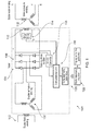
- a typical brushless synchronous generator 100 is shown in Fig. 1 with the present invention applied to it.
- the generator 100 includes an exciter field winding 102 located on a stator (not shown).
- Rotor element 104 includes an exciter armature winding 106.
- Armature winding 106 typically includes a plurality of armatures, so as to output a multiphase (or polyphase) AC signal.
- exciter armature winding 106 includes three armatures, each generating a respective phase of the overall signal output by the exciter armature winding 106.
- exciter armature winding 106 outputs a three-phase AC signal.
- Each phase of the AC signal is fed to a respective rectifying sub-circuit (or branch) of AC rectifying circuit 108.
- AC rectifying circuit 108 is mounted on rotor 104, and may thus be referred to as a rotating diode rectifier (circuit), and the individual diodes therein may be referred to as rotating diodes.
- the rectified outputs from each branch of the AC rectifying circuit combine to provide a rectified output signal to the main field winding 110 located on the rotor 104.
- Rotation of the rotor induces a current in the stator main armature winding 112.
- the stator main armature winding 112 typically includes a plurality of armatures, thereby generating a multiphase output signal.
- stator main armature winding includes three armatures, resulting in a three phase output signal.
- This present invention provides a fast (responsive) and accurate method to detect a rotating diode fault (or failure) in one or more of the rotating diodes provided in AC rectifying circuit 108. It also provides a circuit to measure and extract the fault signature from a measured signal which allows the type of rotating diode fault (or failure) to be detected. For example, the present invention provides, in an aspect, the ability to distinguish between open and short circuit diode faults (failures).
- the present invention is able to achieve this elegant solution employing only a single sensor, which is a significant improvement over the prior art.
- the proposed fault detection method relies on only a single voltage sensor 114, which is used to measure the voltage of the main field winding 110 as shown in Fig. 1 .
- the voltage sensor 114 outputs a signal indicative of the voltage measured across the rotor field winding 110 to a computational unit 116.
- Computational unit is arranged to process the signal received from the voltage sensor 114 to determine whether or not a fault (or a failure) has occurred in one or more of the rotating diodes. This will be explained in more detail below. But, in essence, the measured main field winding DC voltage (as shown in Fig. 4 ) is used to derive a diode failure indication signal based upon a proposed algorithm/methodology.
- a DC-DC converter 118 may also be connected across the main field winding, to supply power to the computational unit.
- the thermo electric generators or any other energy harvesting method could also be used to generate electrical power for supplying the computational unit 116.
- heat energy could be harvested from diode heat sink or bearing.
- Self-powered current sensors may be used to eliminate the need of power source.
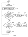
- Fig. 2 shows a flowchart of the proposed fault detection algorithm/methodology.
- the present invention allows detection of both rotating diode open circuit fault and rotating diode short circuit fault conditions.
- the voltage sensor 114 acquires (measures) the voltage across the rotor field winding 110, and transmits to the computational unit 116 a sensor signal indicative of the measured voltage.
- S101 may be thought of as a step of the computational unit 116 acquiring a (sensor) signal indicative of the voltage measured across a load, for example the rotor field winding.
- the load presents a frequency dependent impedance to the output of the AC signal rectifying circuit.
- the computational unit performs processing of the received sensor signal, to derive a value for the ratio of e.g. the fundamental harmonic frequency to another harmonic frequency, for example the 6 th harmonic frequency, of the measured voltage.
- the computational unit 116 may determine the magnitude (amplitude) of the fundamental harmonic frequency of the measured voltage.
- the computational unit 116 may determine the magnitude (amplitude) of the another harmonic frequency of the measured voltage, for example the 6 th harmonic frequency, of the measured voltage.
- the computational unit 116 thereafter calculates the ratio of the respective magnitudes (amplitudes).
- Steps S101 and S102 may be performed continuously, to generate a series of derived values over time.
- the computational unit checks whether or not the derived value(s) is within a predetermined range of fault values. For example, in practice, the computational unit 116 may check whether the derived value(s) is within a range of (fault) values defined by a first threshold value and a second threshold value. If the derived value(s) is within the first and second thresholds, then this may indicate that a fault has occurred with one or more rotating diodes.
- the computational unit 116 monitors whether or not a series of derived values, generated over time, remain within the range defined by the first and second threshold values for a predetermined length of time. If the derived values do so, then the computational unit 116 is configured to determine that a fault has occurred.
- the computational unit 116 is configured to determine that an open circuit fault (or failure) has occurred in one or more of the rotating diodes.
- the computational unit 116 is also configured to determine whether or not a different type of fault (or failure) has occurred in one or more of the rotating diodes. Specifically, the computational unit 116 is configured to determine that a short circuit fault (or failure) has occurred in one or more of the rotating diodes. The computational unit 116 makes this determination in step S106.
- Step S106 may be performed before, after or simultaneously with step 103.
- step S106 the computational unit checks whether or not the derived value(s) is within another predetermined range of fault values.
- the computational unit 116 may check whether the derived value(s) is within a range of (fault) values demarcated from the predetermined range of values referred to in S103 by the second threshold value. In other words, in a preferred embodiment, if the derived value(s) are greater than both the first and second thresholds, then this may indicate that the different type of fault has occurred with one or more rotating diodes.
- the computational unit 116 monitors whether or not a series of derived values, generated over time, remain within the range of values above the second threshold value (e.g. whether they exceed the second threshold value) for a predetermined length of time. If the derived values do so, then the computational unit 116 is configured to determine that the different type of fault (or failure) has occurred in one or more of the rotating diodes.
- the computational unit 116 when the series of derived values, generated over time, remain above the second threshold value for the predetermined length of time, the computational unit 116 is configured to determine that a short circuit fault (or failure) has occurred in one or more of the rotating diodes.
- the predetermined length of time in S103 is preferably the same as that in S104, but it may not be.
- the computational unit may conclude in S109 that the rotating diodes are operating normally.
- S109 may be performed simultaneously with S103 and/or S104. Or, it may not be positively performed at all. In other words, no conclusion regarding normal operation of the rotating diodes may be reached.
- the method may simply monitor for faults, or failures, in the rotating diodes, and thus may only reach a positive conclusion when a fault, or failure, is determined to have occurred.
- the conclusion may be that the rotating diodes are operating normally.
- the example of where the first and/or second thresholds are exceeded is used to determine when a fault has occurred.
- the same determination may be made when the derived value(s) are found to be less than both the first and second thresholds.
- the derived value(s) exceeding the first and second threshold values is indicative of one or more rotating diodes experiencing the fault (or failure).
- the computational unit may issue a control signal to control the generator's output, as in step S105, for example to define a reduced upper limit to the output of the generator, pending repair of the faulty or failed rotating diode.
- the control signal may be a trip signal for stopping operation of the generator.
- step S107 when it is determined in step S107 that an short circuit fault (or failure) has occurred, then the computational unit preferably issues a trip signal to stop operation of the generator, as in step S108, pending repair of the faulty or failed rotating diode.
- the rotating diode failure signature can be derived from a rotor field winding voltage measurement, where harmonic analysis is performed and a ratio of e.g. fundamental to e.g. sixth harmonic voltage magnitude is derived. This ratio can be used to detect the rotating diode failure according to the proposed algorithm/methodology by comparison with pre-defined threshold values to determine the faulty condition.
- the ratio is within predetermined normal values, it is detected as a diode normal operation. However, if the ratio is within the values of threshold 1 and threshold 2 for a predetermined time, it is detected as a rotating diode open circuit failure. Further, if the ratio exceeds the threshold value2 for more than a predetermined time, it is detected as a rotating diode short circuit failure.
- the measured data can be processed by a computational unit according to the described algorithm/methodology; and a final control signal can be transferred to a radio telemetry receiver 122 located on the stator via a rotating radio telemetry transmitter 120 located on the rotor.
- Receiver 122 collects the control signal from the rotor transmitter 120.
- the control signal is preferably arranged to trip the generator during diode short circuit failure. If a diode fails open-circuit, this will reduce the output capacity of the exciter. However, the alternator should still be able to deliver rated output with an open-circuit diode for limited period of time.
- the rotor transmitter 120 sends the control signal to the stationary receiver 122 and a generator control unit (not shown) decides the operation of the generator based on load condition and criticality of the load.
- the proposed algorithm/methodology is able to detect and identify the diode failure condition in a rotating rectifier circuit within a very short period of time compared to existing methods.
- the rotor field winding voltage is measured for the fast detection of diode failures.
- the present invention can be implemented using one voltage sensor mounted in the exciter armature, and optional single wireless control signals can be passed to the stator when a rotating diode failure is detected. This greatly reduces the number of sensors. And it reduces the number of transmitting signals used in the rotor.
- the proposed detection method is very fast due to direct measurement of main field winding voltage and it is particularly suitable for use with brushless synchronous machines, e.g. generators.
- the proposed algorithm/methodology has been verified by the inventors by way of simulation in a MATLAB/Simulink environment.
- a simulation model of the brushless synchronous generator (BLSG) has been developed to include a rotating rectifier circuit using MATLAB/Simulink software.
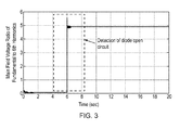
- Fig.3 shows the result of deriving a value for the ratio of the fundamental to sixth harmonic magnitude with one open circuited rotating diode.
- the threshold value may be taken to be 3 or 4 on the y-axis of the plot, for example.
- Failure (fault) detection is possible within a very short period of time due to direct measurement of main field winding voltage. For example, the fault can be detected with certainty within around 2 seconds of the fault occurring.
- Fig. 4 shows the result of deriving a value for the ratio of the fundamental to sixth harmonic magnitude with one short circuited rotating diode. Immediately, it is clear that the values on the y-axis are significantly larger than the values on the y-axis in the plot shown in Fig. 3 .
- the (higher) threshold value may be defined to be 7 or 8.
- the derived value persists above the two thresholds for many seconds, whilst failure detection is possible within a very short period of time.
- the present invention provides a method and apparatus suitable for detecting the occurrence of diode failure in an AC signal rectifier circuit, in particular a rotating rectifier provided in an exciter circuit for supply a rotor main winding in a brushless synchronous machine, e.g. a generator.
- a modified generator 100' may further include a current sensor 115 to measure the current flowing to the rotor field winding100.
- Current sensor 115 may be self-powered.
- the computational unit may receive a current sensor signal indicative of the current flowing to the rotor field winding 110 from the current sensor 115.
- Computational unit 116 may therefore be arranged to derive a value for the ratio of the rotor field voltage to rotor field current fundamental harmonic to another harmonic (e.g. 6 th harmonic) magnitude (amplitude), i.e. using both received signals.
- another harmonic e.g. 6 th harmonic
- Fig. 6 the algorithm/methodology for determining a fault (or a failure) in one or more rotating diodes is shown for the configuration in Fig. 5 .
- step S201 the voltage across the main field winding 110 is acquired, e.g. measured, and the current flowing to the main field winding 110 is acquired, e.g. measured.
- step 202 the ratio of the measured voltage to the measured current is calculated; and the ratio of the fundamental harmonic to the sixth harmonic magnitude of the calculated ratio of the measured voltage to the measured current is derived.
- This derived value is used to provide a fault indicator to detect rotating diode open and short circuit faults.
- the computational unit 116 may include a computer program for executing one or more of steps S101-S109.
- the computational unit 116 may include a computer program for executing one or more of steps S201-S209.
- the present invention may provide a computer program which when executed by a computer executes a method according to the present invention, for example as that described in the appended claims.
- the present invention may be embodied in software.
- the present invention may provide a computer readable medium, on which is stored a set of computer executable instructions, which when executed by a computer perform a method according to the present invention, for example as that described in the appended claims.
- the present invention is applicable to both small and large induction machines, e.g. BLSG machines) for the fast detection of rectifier failure.
- BLSG machines small and large induction machines
- requirements for civil and defence aircrafts are growing and driving the need for More Electric Aircraft (MEA).
- MEA More Electric Aircraft
- advances in power electronics and electrical machines have permitted the use of BLSG coupled to gas turbine engines.
- Such applications require fast detection of rectifier failure to avoid severe damage to the BLSG exciter circuit (including the exciter armature winding and the rotating diode rectifier circuit) and generator control unit.
- a current sensor provided to measure the current of the exciter field winding 102.
- the ratio of the fundamental to the sixth harmonic magnitude may be calculated from the single current measurement. The ratio may then be compared to the pre-determined ranges to determine whether there is a diode failure. In particular, to indicate if there is a short circuit, open circuit or no diode failure.
Applications Claiming Priority (1)
| Application Number | Priority Date | Filing Date | Title |
|---|---|---|---|
| GBGB1400702.5A GB201400702D0 (en) | 2014-01-16 | 2014-01-16 | Rectifier diode fault detection in brushless exciters |
Publications (3)
| Publication Number | Publication Date |
|---|---|
| EP2908148A2 true EP2908148A2 (fr) | 2015-08-19 |
| EP2908148A3 EP2908148A3 (fr) | 2015-09-23 |
| EP2908148B1 EP2908148B1 (fr) | 2019-04-03 |
Family
ID=50239017
Family Applications (1)
| Application Number | Title | Priority Date | Filing Date |
|---|---|---|---|
| EP14198324.7A Active EP2908148B1 (fr) | 2014-01-16 | 2014-12-16 | Détection de défaillances de diode redresseuse dans des dispositifs d'excitation sans balais |
Country Status (3)
| Country | Link |
|---|---|
| US (1) | US9910083B2 (fr) |
| EP (1) | EP2908148B1 (fr) |
| GB (1) | GB201400702D0 (fr) |
Cited By (4)
| Publication number | Priority date | Publication date | Assignee | Title |
|---|---|---|---|---|
| EP3214757A1 (fr) * | 2015-12-04 | 2017-09-06 | Rolls-Royce plc | Procédé et appareil de détection de défaillance de composant de machine électrique |
| CN107976616A (zh) * | 2017-08-25 | 2018-05-01 | 深圳奥特迅电力设备股份有限公司 | 一种智能充电模块输出二极管故障检测方法及装置 |
| CN108603916A (zh) * | 2016-01-27 | 2018-09-28 | 罗伯特·博世有限公司 | 用于识别发电机单元中的故障的方法 |
| WO2022007778A1 (fr) * | 2020-07-06 | 2022-01-13 | 南京航空航天大学 | Procédé de diagnostic de défaut de multiples circuits ouverts applicable à un dispositif d'entraînement de moteur électrique multiphase |
Families Citing this family (13)
| Publication number | Priority date | Publication date | Assignee | Title |
|---|---|---|---|---|
| GB201400701D0 (en) * | 2014-01-16 | 2014-03-05 | Rolls Royce Plc | Fault detection in brushless exciters |
| US9209741B2 (en) * | 2014-02-24 | 2015-12-08 | The Boeing Company | Method and system for controlling synchronous machine as generator/starter |
| US10305356B2 (en) | 2014-09-26 | 2019-05-28 | The Boeing Company | Synchronous machine with common motor/generator exciter stage |
| DE102015009312B4 (de) * | 2015-07-17 | 2017-05-18 | Audi Ag | Diodentest bei einem Kraftfahrzeug-Generator |
| CN105548856B (zh) * | 2015-12-28 | 2018-07-06 | 国电南瑞科技股份有限公司 | 无刷励磁型式发电机组旋转二极管检测系统及方法 |
| JP6483036B2 (ja) * | 2016-01-18 | 2019-03-13 | 東芝三菱電機産業システム株式会社 | 同期機の回転子励磁システム |
| GB201616900D0 (en) * | 2016-10-05 | 2016-11-16 | Rolls Royce Plc | Brushless synchronous generator stator winding fault |
| US20180172754A1 (en) * | 2016-12-16 | 2018-06-21 | Ge Aviation Systems Llc | Rotating diode fault detection |
| GB2560314B (en) * | 2017-03-06 | 2022-03-30 | Safran Electrical & Power | An electrical machine |
| EP3595167B1 (fr) * | 2018-07-11 | 2021-12-01 | ABB Schweiz AG | Surveillance de l'état d'une machine synchrone sans excitateur |
| CN109596936B (zh) * | 2018-12-21 | 2020-12-08 | 许昌学院 | 航空三相交流励磁系统双旋转二极管开路故障检测方法 |
| CN113311307B (zh) * | 2021-05-28 | 2023-04-07 | 华北电力大学(保定) | 一种三相无刷励磁机旋转整流器二极管开路故障检测方法 |
| ES2918074B2 (es) * | 2022-04-08 | 2023-04-12 | Univ Madrid Politecnica | Método y Sistema de supervisión del sistema de excitación indirecta de una máquina síncrona |
Family Cites Families (11)
| Publication number | Priority date | Publication date | Assignee | Title |
|---|---|---|---|---|
| DE1169577B (de) * | 1963-05-03 | 1964-05-06 | Lloyd Dynamowerke G M B H | Anordnung zur Fehlererfassung von Erreger-gleichrichtern einer schleifringlosen Synchronmaschine |
| JPS57142568A (en) * | 1981-02-27 | 1982-09-03 | Hitachi Ltd | Earth trouble detecting device for dc power transmission system |
| US4471308A (en) * | 1982-09-22 | 1984-09-11 | Ford Motor Company | Method of diagnosing component failure in a DC voltage regulator |
| US4816756A (en) * | 1987-09-03 | 1989-03-28 | Westinghouse Electric Corp. | Circuit and method for statically testing rotating rectifiers in brushless alternators |
| US5315527A (en) * | 1992-01-03 | 1994-05-24 | Beckwith Robert W | Method and apparatus providing half-cycle digitization of AC signals by an analog-to-digital converter |
| US5453901A (en) | 1993-10-12 | 1995-09-26 | General Electric Co. | Detection and protection of excitation system from diode failure |
| DE10244765A1 (de) * | 2001-10-22 | 2003-04-30 | Heidelberger Druckmasch Ag | Verfahren und Vorrichtung zur Überwachung von Zwischenkreisspannungen in Gleichrichtern |
| US8575942B2 (en) * | 2009-12-30 | 2013-11-05 | Electric Power Research Institute, Inc. | Non-contacting method and apparatus for determining contact voltage sources and providing a warning for same |
| US9160164B2 (en) | 2010-03-02 | 2015-10-13 | Accumetrics, Inc. | Method and apparatus for fault detection of series diodes in rectifiers |
| EP2542906B1 (fr) | 2010-03-02 | 2015-05-06 | Accumetrics, Inc. | Procédé et appareil de détection de défaillance de diodes en série dans redresseurs |
| CN103782509B (zh) * | 2011-07-04 | 2016-11-09 | Abb研究有限公司 | 用于检测同步发电机内部绕组故障的系统、计算机程序产品和方法 |
-
2014
- 2014-01-16 GB GBGB1400702.5A patent/GB201400702D0/en not_active Ceased
- 2014-12-16 EP EP14198324.7A patent/EP2908148B1/fr active Active
- 2014-12-17 US US14/573,759 patent/US9910083B2/en active Active
Cited By (6)
| Publication number | Priority date | Publication date | Assignee | Title |
|---|---|---|---|---|
| EP3214757A1 (fr) * | 2015-12-04 | 2017-09-06 | Rolls-Royce plc | Procédé et appareil de détection de défaillance de composant de machine électrique |
| US10082531B2 (en) | 2015-12-04 | 2018-09-25 | Rolls-Royce Plc | Electrical machine component failure detection apparatus and method |
| CN108603916A (zh) * | 2016-01-27 | 2018-09-28 | 罗伯特·博世有限公司 | 用于识别发电机单元中的故障的方法 |
| CN107976616A (zh) * | 2017-08-25 | 2018-05-01 | 深圳奥特迅电力设备股份有限公司 | 一种智能充电模块输出二极管故障检测方法及装置 |
| CN107976616B (zh) * | 2017-08-25 | 2020-02-14 | 深圳奥特迅电力设备股份有限公司 | 一种智能充电模块输出二极管故障检测方法及装置 |
| WO2022007778A1 (fr) * | 2020-07-06 | 2022-01-13 | 南京航空航天大学 | Procédé de diagnostic de défaut de multiples circuits ouverts applicable à un dispositif d'entraînement de moteur électrique multiphase |
Also Published As
| Publication number | Publication date |
|---|---|
| US20150198655A1 (en) | 2015-07-16 |
| EP2908148B1 (fr) | 2019-04-03 |
| EP2908148A3 (fr) | 2015-09-23 |
| GB201400702D0 (en) | 2014-03-05 |
| US9910083B2 (en) | 2018-03-06 |
Similar Documents
| Publication | Publication Date | Title |
|---|---|---|
| EP2908148B1 (fr) | Détection de défaillances de diode redresseuse dans des dispositifs d'excitation sans balais | |
| US9459320B2 (en) | Fault detection in brushless exciters | |
| EP3306330B1 (fr) | Défaut d'enroulement de stator de générateur synchrone sans balai | |
| US8924170B2 (en) | Method and system for detecting a failed rectifier in an AC/DC converter | |
| RU2563964C2 (ru) | Система, компьютерный программный продукт и способ обнаружения внутренних неисправностей обмотки синхронного генератора | |
| EP2565659B1 (fr) | Système de détection de défaillance pour un générateur | |
| EP2077613B1 (fr) | Détection et protection de diode rotative réduite | |
| EP3480610B1 (fr) | Diagnostic d'un ensemble d'enroulement d'un stator | |
| EP2077612A2 (fr) | Système et procédé de suppression de formation de tension de lien CC due à une réaction d'armature de générateur | |
| US10473708B2 (en) | Methods and systems for real-time monitoring of the insulation state of wind-powered generator windings | |
| US10746803B2 (en) | Fault detection and isolation in generator modules | |
| US9270219B2 (en) | Voltage-controlled DC link for variable frequency generator excitation | |
| US20130194101A1 (en) | System and method for health monitoring of power cables | |
| US7005833B2 (en) | Method of and apparatus for detecting sensor loss in a generator control system | |
| US10082531B2 (en) | Electrical machine component failure detection apparatus and method | |
| EP2772770A1 (fr) | Dispositif de protection contre les défauts de terre de rotor destiné à une machine à induction à double alimentation à vitesse variable électrique | |
| CN110062889A (zh) | 用于检测交流电机中的定子故障的系统和方法 | |
| CN107894549B (zh) | 差分故障检测系统 | |
| US10972030B2 (en) | Multi-stage synchronous generator | |
| US9065270B2 (en) | Ground fault protection systems and methods | |
| RU2734165C1 (ru) | Способ регистрации образования изолированной сети |
Legal Events
| Date | Code | Title | Description |
|---|---|---|---|
| PUAI | Public reference made under article 153(3) epc to a published international application that has entered the european phase |
Free format text: ORIGINAL CODE: 0009012 |
|
| AK | Designated contracting states |
Kind code of ref document: A2 Designated state(s): AL AT BE BG CH CY CZ DE DK EE ES FI FR GB GR HR HU IE IS IT LI LT LU LV MC MK MT NL NO PL PT RO RS SE SI SK SM TR |
|
| AX | Request for extension of the european patent |
Extension state: BA ME |
|
| PUAL | Search report despatched |
Free format text: ORIGINAL CODE: 0009013 |
|
| AK | Designated contracting states |
Kind code of ref document: A3 Designated state(s): AL AT BE BG CH CY CZ DE DK EE ES FI FR GB GR HR HU IE IS IT LI LT LU LV MC MK MT NL NO PL PT RO RS SE SI SK SM TR |
|
| AX | Request for extension of the european patent |
Extension state: BA ME |
|
| RIC1 | Information provided on ipc code assigned before grant |
Ipc: G01R 31/34 20060101AFI20150819BHEP Ipc: H02K 11/04 20060101ALI20150819BHEP Ipc: H02H 7/06 20060101ALI20150819BHEP |
|
| 17P | Request for examination filed |
Effective date: 20160321 |
|
| RBV | Designated contracting states (corrected) |
Designated state(s): AL AT BE BG CH CY CZ DE DK EE ES FI FR GB GR HR HU IE IS IT LI LT LU LV MC MK MT NL NO PL PT RO RS SE SI SK SM TR |
|
| GRAP | Despatch of communication of intention to grant a patent |
Free format text: ORIGINAL CODE: EPIDOSNIGR1 |
|
| STAA | Information on the status of an ep patent application or granted ep patent |
Free format text: STATUS: GRANT OF PATENT IS INTENDED |
|
| INTG | Intention to grant announced |
Effective date: 20190111 |
|
| GRAS | Grant fee paid |
Free format text: ORIGINAL CODE: EPIDOSNIGR3 |
|
| GRAA | (expected) grant |
Free format text: ORIGINAL CODE: 0009210 |
|
| STAA | Information on the status of an ep patent application or granted ep patent |
Free format text: STATUS: THE PATENT HAS BEEN GRANTED |
|
| AK | Designated contracting states |
Kind code of ref document: B1 Designated state(s): AL AT BE BG CH CY CZ DE DK EE ES FI FR GB GR HR HU IE IS IT LI LT LU LV MC MK MT NL NO PL PT RO RS SE SI SK SM TR |
|
| REG | Reference to a national code |
Ref country code: GB Ref legal event code: FG4D |
|
| REG | Reference to a national code |
Ref country code: CH Ref legal event code: EP Ref country code: AT Ref legal event code: REF Ref document number: 1116392 Country of ref document: AT Kind code of ref document: T Effective date: 20190415 |
|
| REG | Reference to a national code |
Ref country code: DE Ref legal event code: R096 Ref document number: 602014043944 Country of ref document: DE |
|
| REG | Reference to a national code |
Ref country code: IE Ref legal event code: FG4D |
|
| REG | Reference to a national code |
Ref country code: NL Ref legal event code: MP Effective date: 20190403 |
|
| REG | Reference to a national code |
Ref country code: LT Ref legal event code: MG4D |
|
| REG | Reference to a national code |
Ref country code: AT Ref legal event code: MK05 Ref document number: 1116392 Country of ref document: AT Kind code of ref document: T Effective date: 20190403 |
|
| PG25 | Lapsed in a contracting state [announced via postgrant information from national office to epo] |
Ref country code: NL Free format text: LAPSE BECAUSE OF FAILURE TO SUBMIT A TRANSLATION OF THE DESCRIPTION OR TO PAY THE FEE WITHIN THE PRESCRIBED TIME-LIMIT Effective date: 20190403 |
|
| PG25 | Lapsed in a contracting state [announced via postgrant information from national office to epo] |
Ref country code: LT Free format text: LAPSE BECAUSE OF FAILURE TO SUBMIT A TRANSLATION OF THE DESCRIPTION OR TO PAY THE FEE WITHIN THE PRESCRIBED TIME-LIMIT Effective date: 20190403 Ref country code: ES Free format text: LAPSE BECAUSE OF FAILURE TO SUBMIT A TRANSLATION OF THE DESCRIPTION OR TO PAY THE FEE WITHIN THE PRESCRIBED TIME-LIMIT Effective date: 20190403 Ref country code: CZ Free format text: LAPSE BECAUSE OF FAILURE TO SUBMIT A TRANSLATION OF THE DESCRIPTION OR TO PAY THE FEE WITHIN THE PRESCRIBED TIME-LIMIT Effective date: 20190403 Ref country code: SE Free format text: LAPSE BECAUSE OF FAILURE TO SUBMIT A TRANSLATION OF THE DESCRIPTION OR TO PAY THE FEE WITHIN THE PRESCRIBED TIME-LIMIT Effective date: 20190403 Ref country code: HR Free format text: LAPSE BECAUSE OF FAILURE TO SUBMIT A TRANSLATION OF THE DESCRIPTION OR TO PAY THE FEE WITHIN THE PRESCRIBED TIME-LIMIT Effective date: 20190403 Ref country code: FI Free format text: LAPSE BECAUSE OF FAILURE TO SUBMIT A TRANSLATION OF THE DESCRIPTION OR TO PAY THE FEE WITHIN THE PRESCRIBED TIME-LIMIT Effective date: 20190403 Ref country code: NO Free format text: LAPSE BECAUSE OF FAILURE TO SUBMIT A TRANSLATION OF THE DESCRIPTION OR TO PAY THE FEE WITHIN THE PRESCRIBED TIME-LIMIT Effective date: 20190703 Ref country code: PT Free format text: LAPSE BECAUSE OF FAILURE TO SUBMIT A TRANSLATION OF THE DESCRIPTION OR TO PAY THE FEE WITHIN THE PRESCRIBED TIME-LIMIT Effective date: 20190803 Ref country code: AL Free format text: LAPSE BECAUSE OF FAILURE TO SUBMIT A TRANSLATION OF THE DESCRIPTION OR TO PAY THE FEE WITHIN THE PRESCRIBED TIME-LIMIT Effective date: 20190403 |
|
| PG25 | Lapsed in a contracting state [announced via postgrant information from national office to epo] |
Ref country code: LV Free format text: LAPSE BECAUSE OF FAILURE TO SUBMIT A TRANSLATION OF THE DESCRIPTION OR TO PAY THE FEE WITHIN THE PRESCRIBED TIME-LIMIT Effective date: 20190403 Ref country code: PL Free format text: LAPSE BECAUSE OF FAILURE TO SUBMIT A TRANSLATION OF THE DESCRIPTION OR TO PAY THE FEE WITHIN THE PRESCRIBED TIME-LIMIT Effective date: 20190403 Ref country code: GR Free format text: LAPSE BECAUSE OF FAILURE TO SUBMIT A TRANSLATION OF THE DESCRIPTION OR TO PAY THE FEE WITHIN THE PRESCRIBED TIME-LIMIT Effective date: 20190704 Ref country code: BG Free format text: LAPSE BECAUSE OF FAILURE TO SUBMIT A TRANSLATION OF THE DESCRIPTION OR TO PAY THE FEE WITHIN THE PRESCRIBED TIME-LIMIT Effective date: 20190703 Ref country code: RS Free format text: LAPSE BECAUSE OF FAILURE TO SUBMIT A TRANSLATION OF THE DESCRIPTION OR TO PAY THE FEE WITHIN THE PRESCRIBED TIME-LIMIT Effective date: 20190403 |
|
| PG25 | Lapsed in a contracting state [announced via postgrant information from national office to epo] |
Ref country code: AT Free format text: LAPSE BECAUSE OF FAILURE TO SUBMIT A TRANSLATION OF THE DESCRIPTION OR TO PAY THE FEE WITHIN THE PRESCRIBED TIME-LIMIT Effective date: 20190403 Ref country code: IS Free format text: LAPSE BECAUSE OF FAILURE TO SUBMIT A TRANSLATION OF THE DESCRIPTION OR TO PAY THE FEE WITHIN THE PRESCRIBED TIME-LIMIT Effective date: 20190803 |
|
| REG | Reference to a national code |
Ref country code: DE Ref legal event code: R097 Ref document number: 602014043944 Country of ref document: DE |
|
| PG25 | Lapsed in a contracting state [announced via postgrant information from national office to epo] |
Ref country code: RO Free format text: LAPSE BECAUSE OF FAILURE TO SUBMIT A TRANSLATION OF THE DESCRIPTION OR TO PAY THE FEE WITHIN THE PRESCRIBED TIME-LIMIT Effective date: 20190403 Ref country code: SK Free format text: LAPSE BECAUSE OF FAILURE TO SUBMIT A TRANSLATION OF THE DESCRIPTION OR TO PAY THE FEE WITHIN THE PRESCRIBED TIME-LIMIT Effective date: 20190403 Ref country code: EE Free format text: LAPSE BECAUSE OF FAILURE TO SUBMIT A TRANSLATION OF THE DESCRIPTION OR TO PAY THE FEE WITHIN THE PRESCRIBED TIME-LIMIT Effective date: 20190403 Ref country code: DK Free format text: LAPSE BECAUSE OF FAILURE TO SUBMIT A TRANSLATION OF THE DESCRIPTION OR TO PAY THE FEE WITHIN THE PRESCRIBED TIME-LIMIT Effective date: 20190403 |
|
| PLBE | No opposition filed within time limit |
Free format text: ORIGINAL CODE: 0009261 |
|
| STAA | Information on the status of an ep patent application or granted ep patent |
Free format text: STATUS: NO OPPOSITION FILED WITHIN TIME LIMIT |
|
| RAP2 | Party data changed (patent owner data changed or rights of a patent transferred) |
Owner name: ROLLS-ROYCE PLC |
|
| PG25 | Lapsed in a contracting state [announced via postgrant information from national office to epo] |
Ref country code: IT Free format text: LAPSE BECAUSE OF FAILURE TO SUBMIT A TRANSLATION OF THE DESCRIPTION OR TO PAY THE FEE WITHIN THE PRESCRIBED TIME-LIMIT Effective date: 20190403 Ref country code: SM Free format text: LAPSE BECAUSE OF FAILURE TO SUBMIT A TRANSLATION OF THE DESCRIPTION OR TO PAY THE FEE WITHIN THE PRESCRIBED TIME-LIMIT Effective date: 20190403 |
|
| 26N | No opposition filed |
Effective date: 20200106 |
|
| PG25 | Lapsed in a contracting state [announced via postgrant information from national office to epo] |
Ref country code: TR Free format text: LAPSE BECAUSE OF FAILURE TO SUBMIT A TRANSLATION OF THE DESCRIPTION OR TO PAY THE FEE WITHIN THE PRESCRIBED TIME-LIMIT Effective date: 20190403 |
|
| PG25 | Lapsed in a contracting state [announced via postgrant information from national office to epo] |
Ref country code: SI Free format text: LAPSE BECAUSE OF FAILURE TO SUBMIT A TRANSLATION OF THE DESCRIPTION OR TO PAY THE FEE WITHIN THE PRESCRIBED TIME-LIMIT Effective date: 20190403 |
|
| REG | Reference to a national code |
Ref country code: CH Ref legal event code: PL |
|
| REG | Reference to a national code |
Ref country code: BE Ref legal event code: MM Effective date: 20191231 |
|
| PG25 | Lapsed in a contracting state [announced via postgrant information from national office to epo] |
Ref country code: MC Free format text: LAPSE BECAUSE OF FAILURE TO SUBMIT A TRANSLATION OF THE DESCRIPTION OR TO PAY THE FEE WITHIN THE PRESCRIBED TIME-LIMIT Effective date: 20190403 |
|
| PG25 | Lapsed in a contracting state [announced via postgrant information from national office to epo] |
Ref country code: IE Free format text: LAPSE BECAUSE OF NON-PAYMENT OF DUE FEES Effective date: 20191216 Ref country code: LU Free format text: LAPSE BECAUSE OF NON-PAYMENT OF DUE FEES Effective date: 20191216 |
|
| PG25 | Lapsed in a contracting state [announced via postgrant information from national office to epo] |
Ref country code: LI Free format text: LAPSE BECAUSE OF NON-PAYMENT OF DUE FEES Effective date: 20191231 Ref country code: CH Free format text: LAPSE BECAUSE OF NON-PAYMENT OF DUE FEES Effective date: 20191231 Ref country code: BE Free format text: LAPSE BECAUSE OF NON-PAYMENT OF DUE FEES Effective date: 20191231 |
|
| PG25 | Lapsed in a contracting state [announced via postgrant information from national office to epo] |
Ref country code: CY Free format text: LAPSE BECAUSE OF FAILURE TO SUBMIT A TRANSLATION OF THE DESCRIPTION OR TO PAY THE FEE WITHIN THE PRESCRIBED TIME-LIMIT Effective date: 20190403 |
|
| PG25 | Lapsed in a contracting state [announced via postgrant information from national office to epo] |
Ref country code: MT Free format text: LAPSE BECAUSE OF FAILURE TO SUBMIT A TRANSLATION OF THE DESCRIPTION OR TO PAY THE FEE WITHIN THE PRESCRIBED TIME-LIMIT Effective date: 20190403 Ref country code: HU Free format text: LAPSE BECAUSE OF FAILURE TO SUBMIT A TRANSLATION OF THE DESCRIPTION OR TO PAY THE FEE WITHIN THE PRESCRIBED TIME-LIMIT; INVALID AB INITIO Effective date: 20141216 |
|
| PG25 | Lapsed in a contracting state [announced via postgrant information from national office to epo] |
Ref country code: MK Free format text: LAPSE BECAUSE OF FAILURE TO SUBMIT A TRANSLATION OF THE DESCRIPTION OR TO PAY THE FEE WITHIN THE PRESCRIBED TIME-LIMIT Effective date: 20190403 |
|
| PGFP | Annual fee paid to national office [announced via postgrant information from national office to epo] |
Ref country code: DE Payment date: 20221227 Year of fee payment: 9 |
|
| P01 | Opt-out of the competence of the unified patent court (upc) registered |
Effective date: 20230528 |
|
| PGFP | Annual fee paid to national office [announced via postgrant information from national office to epo] |
Ref country code: GB Payment date: 20231219 Year of fee payment: 10 |
|
| PGFP | Annual fee paid to national office [announced via postgrant information from national office to epo] |
Ref country code: FR Payment date: 20231226 Year of fee payment: 10 |