EP2077612A2 - Système et procédé de suppression de formation de tension de lien CC due à une réaction d'armature de générateur - Google Patents
Système et procédé de suppression de formation de tension de lien CC due à une réaction d'armature de générateur Download PDFInfo
- Publication number
- EP2077612A2 EP2077612A2 EP08254191A EP08254191A EP2077612A2 EP 2077612 A2 EP2077612 A2 EP 2077612A2 EP 08254191 A EP08254191 A EP 08254191A EP 08254191 A EP08254191 A EP 08254191A EP 2077612 A2 EP2077612 A2 EP 2077612A2
- Authority
- EP
- European Patent Office
- Prior art keywords
- voltage
- controller
- generator
- short
- field winding
- Prior art date
- Legal status (The legal status is an assumption and is not a legal conclusion. Google has not performed a legal analysis and makes no representation as to the accuracy of the status listed.)
- Granted
Links
- 238000000034 method Methods 0.000 title claims description 10
- 238000004804 winding Methods 0.000 claims abstract description 62
- 230000005284 excitation Effects 0.000 claims abstract description 14
- 230000001360 synchronised effect Effects 0.000 claims abstract description 6
- 230000010363 phase shift Effects 0.000 claims description 4
- 238000012544 monitoring process Methods 0.000 claims description 3
- 238000001514 detection method Methods 0.000 claims description 2
- 238000004590 computer program Methods 0.000 claims 2
- 238000010586 diagram Methods 0.000 description 6
- 238000007493 shaping process Methods 0.000 description 6
- 238000001914 filtration Methods 0.000 description 4
- 238000012546 transfer Methods 0.000 description 4
- 230000000694 effects Effects 0.000 description 3
- 230000010354 integration Effects 0.000 description 2
- 230000009286 beneficial effect Effects 0.000 description 1
- 230000001143 conditioned effect Effects 0.000 description 1
- 230000003247 decreasing effect Effects 0.000 description 1
- 238000013461 design Methods 0.000 description 1
- 230000004069 differentiation Effects 0.000 description 1
- 238000012545 processing Methods 0.000 description 1
- 208000024891 symptom Diseases 0.000 description 1
- 230000001960 triggered effect Effects 0.000 description 1
Images


Classifications
-
- H—ELECTRICITY
- H02—GENERATION; CONVERSION OR DISTRIBUTION OF ELECTRIC POWER
- H02P—CONTROL OR REGULATION OF ELECTRIC MOTORS, ELECTRIC GENERATORS OR DYNAMO-ELECTRIC CONVERTERS; CONTROLLING TRANSFORMERS, REACTORS OR CHOKE COILS
- H02P9/00—Arrangements for controlling electric generators for the purpose of obtaining a desired output
- H02P9/10—Control effected upon generator excitation circuit to reduce harmful effects of overloads or transients, e.g. sudden application of load, sudden removal of load, sudden change of load
-
- H—ELECTRICITY
- H02—GENERATION; CONVERSION OR DISTRIBUTION OF ELECTRIC POWER
- H02H—EMERGENCY PROTECTIVE CIRCUIT ARRANGEMENTS
- H02H7/00—Emergency protective circuit arrangements specially adapted for specific types of electric machines or apparatus or for sectionalised protection of cable or line systems, and effecting automatic switching in the event of an undesired change from normal working conditions
- H02H7/06—Emergency protective circuit arrangements specially adapted for specific types of electric machines or apparatus or for sectionalised protection of cable or line systems, and effecting automatic switching in the event of an undesired change from normal working conditions for dynamo-electric generators; for synchronous capacitors
- H02H7/065—Emergency protective circuit arrangements specially adapted for specific types of electric machines or apparatus or for sectionalised protection of cable or line systems, and effecting automatic switching in the event of an undesired change from normal working conditions for dynamo-electric generators; for synchronous capacitors against excitation faults
-
- H—ELECTRICITY
- H02—GENERATION; CONVERSION OR DISTRIBUTION OF ELECTRIC POWER
- H02P—CONTROL OR REGULATION OF ELECTRIC MOTORS, ELECTRIC GENERATORS OR DYNAMO-ELECTRIC CONVERTERS; CONTROLLING TRANSFORMERS, REACTORS OR CHOKE COILS
- H02P9/00—Arrangements for controlling electric generators for the purpose of obtaining a desired output
- H02P9/14—Arrangements for controlling electric generators for the purpose of obtaining a desired output by variation of field
- H02P9/26—Arrangements for controlling electric generators for the purpose of obtaining a desired output by variation of field using discharge tubes or semiconductor devices
- H02P9/30—Arrangements for controlling electric generators for the purpose of obtaining a desired output by variation of field using discharge tubes or semiconductor devices using semiconductor devices
- H02P9/305—Arrangements for controlling electric generators for the purpose of obtaining a desired output by variation of field using discharge tubes or semiconductor devices using semiconductor devices controlling voltage
-
- G—PHYSICS
- G01—MEASURING; TESTING
- G01R—MEASURING ELECTRIC VARIABLES; MEASURING MAGNETIC VARIABLES
- G01R31/00—Arrangements for testing electric properties; Arrangements for locating electric faults; Arrangements for electrical testing characterised by what is being tested not provided for elsewhere
- G01R31/34—Testing dynamo-electric machines
- G01R31/343—Testing dynamo-electric machines in operation
-
- G—PHYSICS
- G01—MEASURING; TESTING
- G01R—MEASURING ELECTRIC VARIABLES; MEASURING MAGNETIC VARIABLES
- G01R31/00—Arrangements for testing electric properties; Arrangements for locating electric faults; Arrangements for electrical testing characterised by what is being tested not provided for elsewhere
- G01R31/50—Testing of electric apparatus, lines, cables or components for short-circuits, continuity, leakage current or incorrect line connections
- G01R31/52—Testing for short-circuits, leakage current or ground faults
Definitions
- the present invention is related to generators and in particular to control schemes for suppressing DC link voltage build-up in generators due to unbalanced short circuit conditions.
- an alternating current (AC) output voltage is controlled based on the magnitude of an exciter current provided as an input to an exciter field winding.
- a permanent magnet generator and a rectifier circuit are used to provide a DC link voltage.
- the DC link voltage is employed to provide a DC current of a desired magnitude to the exciter field winding.
- An AC voltage induced in the exciter rotor windings is converted to a DC voltage by a rotating rectifier circuit and provided as excitation to a main field winding.
- an AC output voltage is generated in the main armature winding that is then provided to a load.
- the output voltage and/or output current of the generator are provided as feedback to a controller that controls the magnitude of the DC current provided to the exciter field winding. In this way, the output voltage of the generator is maintained at a desired magnitude.
- the controller may also monitor the DC link voltage. In response to an increase in the magnitude of the DC link voltage, the controller orders a shutdown of the generator.
- problems arise when unbalanced short circuit faults at the output of the generator are transmitted through armature reaction to the DC link voltage.
- the unbalanced short-circuit fault results in the magnitude of the DC link voltage increasing such that a shutdown of the generator is triggered by a condition in which it is preferable to maintain the operation of the generator. It would therefore be beneficial to prevent the buildup of DC link voltage in response to an unbalanced short-circuit fault to prevent the improper shutdown of the generator.
- a controller for use in a synchronous generator system that includes an exciter field winding, an exciter armature winding, a main field winding, and a main armature winding.
- the controller includes a first input operably connected to monitor the output voltage of the synchronous generator and a voltage calculator operably connected to the first inputs to calculate a value representative of the average output voltage.
- the controller includes a compensation loop operably connected to the voltage calculator that detects voltage ripples, if any, in the average output voltage and modifies the shape of the voltage ripple to generate a compensated signal.
- the controller further includes an output operably connected to control the excitation provided to the exciter field winding based on the compensated signal. Proper shaping of the voltage ripple by the control loop results in a compensated signal that will counteract armature reaction voltage ripple generated as a result of an unbalanced short-circuit fault, thereby preventing the build-up of voltage on the DC link.
- FIG. 1 is a block diagram of a simplified generator system.
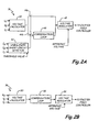
- FIGS. 2A and 2B are block diagrams illustrating an exemplary embodiment of the controller of the present invention.
- FIG. 3 is a block diagram of a compensation loop employed by the controller of the present invention to provide the proper shaping of the monitored output voltage such that application of the resulting compensated signal prevents the buildup of DC link voltage.
- FIG. 1 is a block diagram of simplified generator system 10 of the present invention, which includes permanent magnet generator (PMG) 12, rectifier circuit 14, active switch circuit 16, and generator 18.
- generator 18 includes exciter field winding 20, rotating module 22, exciter armature winding 24, rotating rectifier 26, main field winding 28, and main armature winding 30.
- generator system 10 includes controller 36 and exciter field controller 38.
- a rotating shaft (not shown) provides mechanical energy to PMG 12 and rotating module 22.
- the mechanical energy provided to PMG 12 is converted to alternating current (AC) voltage.
- Rectifier circuit 14 converts the AC voltage to a direct current (DC) voltage that is provided to active switch circuit 16. This DC voltage is commonly referred to as the DC link voltage.
- Controller 36 and exciter current loop 38 based on feedback received at the output of main generator 30, provide pulse width modulated (PWM) control signals to switch circuit 16 to control the DC current (commonly referred to as the exciter field current) provided to exciter field winding 20. Based on the magnitude of the DC current provided to exciter field windings 20, the magnitude of the AC output voltage provided to load 34 can be controlled.
- PWM pulse width modulated
- controller 36 monitors the output voltage of generator 18 and adjusts the excitation provided to exciter field windings 20 to control the generator output voltage as desired. In particular, controller 36 typically converts the monitored AC output voltage to a steady-state or DC representation of the output voltage.
- controller 36 causes exciter current loop 38 to selectively increase or decrease the excitation provided to exciter field winding 20. In this way, the AC output voltage generated by generator 10 is controlled to a desired value.
- another type of fault known as a line-to-line, line-to-line-to-neutral fault or line-to-neutral fault on the output of generator 18 causes a similar increase in the DC link voltage.
- An unbalanced fault such as a line-to-line fault, line-to-line-to-neutral fault or a line-to-neutral fault causes the voltage on the shorted phase to decrease to a level less than the voltage on the non-shorted phases, resulting in an unbalanced fault.
- the average value of the output voltage will include a voltage ripple effect that is transmitted by armature reaction within generator 18 to exciter field winding 20 (referred to hereinafter as the "armature reaction voltage ripple").
- the DC link voltage increases in magnitude.
- circuit breakers located downstream from generating system 10 will trip, thereby isolating the fault without requiring the shutdown of generating system 10.
- the problem therefore, is that two (or more) different types of faults share a common symptom: the increase in the magnitude of the DC link voltage.
- the present invention is therefore directed towards a control scheme that reduces or prevents entirely the increase in the DC link voltage caused by unbalanced short-circuit conditions.
- the present invention is directed to a simplified solution to the problem that does not require any changes to the hardware of generating system 10.
- the present invention is directed to a control scheme that will cancel out or reduce the armature reaction voltage ripple on the exciter field winding 20, thereby preventing the increase of the DC link voltage in response to an unbalanced short-circuit fault.
- control scheme makes use of the monitored output voltage of generator 18 to generate a compensated signal that is used to counteract the armature reaction voltage ripple. In this way, the control scheme of the present invention prevents the build-up of DC link voltage as a result of unbalanced short-circuit faults, and prevents the untimely shutdown of generating system 10.
- controller 36 monitors the output voltage (labeled V a , V b , and V c ) of generator 18 and (at least in one embodiment) the output current (labeled I a , I b , and I c ) of generator 18.
- the monitored output voltage is provided to a compensation loop that isolates and shapes voltage ripples, if any, within the monitored output voltage.
- the resulting compensated signal is provided to a voltage regulator that compares the signal to a reference value, and provides the error or difference to exciter field controller 38.
- exciter field controller 38 controls the excitation provided to exciter field winding 20.
- the resulting excitation provided to the exciter field winding 20 will counteract or cancel armature reaction voltage ripple caused by unbalanced short-circuit conditions, thereby preventing the buildup of voltage on the DC link.
- FIGS. 2A and 2B are block diagrams illustrating two exemplary embodiments of the operation of controller 36 in generating a compensated signal.
- controller 36 comprises a digital signal processor (DSP) that executes software instructions to perform the functions described with respect to FIGS. 2A and 2B .
- DSP digital signal processor
- a benefit of the present invention is in controllers that already include a DSP only changes to the software executed by the DSP are required to add the functionality of the present invention to an existing generator system.
- other well-known digital signal processing or dedicated circuits may be used to perform the functions described with respect to FIGS. 2A and 2B .
- controller 36 includes voltage calculator 40, unbalanced short-circuit detector 42, switches 44a and 44b, compensation loop 46, and voltage regulator 48.
- unbalanced short-circuit detector 42 monitors the output currents I a , I b , and I c of generator 18.
- an unbalanced short-circuit is typically accompanied by the voltage at one or two phases of the generator output decreasing with respect to the other phases.
- the current associated with the phase of power on which the fault occurs will increase in magnitude.
- detector 42 compares the monitored output current of each phase with a threshold value to determine whether a short-circuit condition exists on any of the monitored phases. Detection of an unbalanced short-circuit condition is conditioned on one or two, but not all three (for instance, in a three-phase system), of the monitored output currents exceeding the threshold value.
- detector 42 determines that an unbalanced short-circuit condition exists. Similarly, if monitored output current I a and I b both exceed the threshold value, while monitored output current I c does not, then detector 42 once again determines that an unbalanced short-circuit condition exists. However, if all three monitored currents I a , I b , and I c exceed the threshold value then detector 42 determines that a short-circuit condition exists, but that the short-circuit condition is balanced rather than unbalanced.
- line-to-line short-circuit conditions line-to-line-to-neutral and/or line-to-neutral short-circuit conditions can be differentiated from balanced short-circuit conditions in which all three phases are shorted.
- the monitored output currents of generator 18 are employed to detect unbalanced short-circuit conditions
- the monitored output voltage may be used either alone or in conjunction with the monitored output current to detect unbalanced short-circuit faults.
- the monitored output voltages V a , V b , and V c of generator 18 are provided as input to voltage calculator 40, which calculates a steady-state or DC value representing the average magnitude of the monitored output voltages.
- the average output voltage may be the root mean square, average mean square, rectified output of the monitored AC output voltages, or any other well known method of representing the average magnitude of an AC output voltage.
- the average voltage value detected by voltage calculation 40 is either provided as an input to compensation loop 46 or voltage regulator 48.
- a determination by detector 42 that no unbalanced short-circuit condition exists results in the average voltage value being supplied (via switch 44a) directly to voltage regulator 48, which compares the average voltage value to a reference value.
- the resulting error signal is provided as an input to exciter field controller 38 (shown in FIG. 1 ). As discussed above, based on the provided error signal, exciter field controller 38 controls the excitation provided to exciter field winding 16, ultimately controlling the output voltage of generator 18.
- a determination by detector 42 that an unbalanced short-circuit condition exists results in the average voltage value being provided (via switch 44b) as an input to compensation loop 46.
- the presence of an unbalanced short-circuit condition will create a voltage ripple within the average voltage value.
- Compensation loop 46 identifies the voltage ripple within the average voltage value, and modifies the phase and magnitude of the identified voltage ripple.
- a compensated signal is provided as an input to voltage regulator 48.
- the compensated signal will include a DC component that represents the average voltage value of the monitored output voltage and an AC component that is a result of the "shaping" functions applied to the voltage ripple component by compensation loop 46.
- Voltage regulator 48 compares the compensated signal provided by compensation loop 46 to a reference value, and the resulting error signal is provided as an input to exciter field controller 38.
- the resulting excitation generated on exciter field winding 20 will include a ripple component properly phased to counteract or cancel the armature reaction voltage ripple that would otherwise cause the DC link voltage to build-up.
- FIG. 2B illustrates another embodiment of controller 36 for generating a compensated signal that will cancel or counteract an armature reaction voltage signal generated as a result of an unbalanced short-circuit fault.
- the embodiment of controller 36 shown in FIG. 2 applies compensation loop 52 to the average voltage value regardless of whether an unbalanced short-circuit fault has been detected.
- compensation loop 52 acts to isolate voltage ripple within the average voltage value provided by voltage calculator 50. In situations in which no unbalanced short-circuit fault exists, no voltage ripple will be present within the average voltage value. As a result, compensation loop 52 should have no effect on the monitored output voltage. However, if an unbalanced short-circuit condition is present such that a voltage ripple exists within the monitored output voltage, compensation loop 52 will act to identify and shape the voltage ripple within the average voltage value.
- the compensated signal is provided as an input to voltage regulator 54, which compares the compensated signal to a reference value to calculate an error value.
- the error value is provided to exciter winding controller 38 (shown in FIG. 1 ).
- exciter winding controller 38 By properly shaping the phase and magnitude of the voltage ripple included within the compensated signal, exciter winding controller 38 causes the excitation provided to exciter field winding 20 to include a ripple component properly phased to counteract or cancel the armature reaction voltage ripple that would otherwise cause the DC link voltage to build-up.
- FIG. 3 is a block diagram illustrating an exemplary embodiment of a compensation loop 60 implemented by controller 36 to prevent the buildup of voltage on the DC link caused by an unbalanced fault condition.
- Compensation loop 60 may be employed in either of the embodiments described with respect to FIGS. 2A and 2B .
- the embodiment shown in FIG. 3 illustrates one method of providing the proper filtering, phase shifting and gain application to the detected ripple voltage such that the compensated signal generated as a result of compensation loop 60 can be used to cancel the armature reaction voltage ripple.
- Other configurations of control functions may be employed to provide the proper filtering, phase shifting, and gain application to a detected voltage ripple.
- compensation loop 60 includes as an input the average voltage 62, gain block 64, summer block 66, saturation block 68, integration block 70, gain block 72, gain block 74, summer block 76, gain block 78, sample rate delay block 80, summer block 82 and compensated signal 84.
- Compensation loop 60 may be applied to the average voltage value only in response to a detected unbalanced short-circuit fault (as shown in FIG. 2A ) or may be applied to the average voltage value regardless of whether an unbalanced short-circuit has been detected (as shown in FIG. 2B ).
- the average voltage value is provided as an input to the compensation loop 60.
- An unbalanced short-circuit fault will generate a voltage ripple in the average voltage value, which compensation loop 60 seeks to identify and shape such that the resulting compensated signal includes a voltage ripple component that has a phase and magnitude that will cancel the armature reaction ripple voltage on the exciter field windings 20.
- the transfer function can be described by the following equation; K • S + Z S + P wherein K represents a gain value, Z represents the zero of the transfer function, and P represents the pole of the transfer function.
- K represents a gain value
- Z represents the zero of the transfer function
- P represents the pole of the transfer function.
- the particular form and values of the transfer function may vary depending on the specifics of the application, but the goal of providing a compensated signal that provides an AC or ripple component properly phased to counteract the effects of armature reaction remains the same.
- the filtering and phase shifting of the average voltage value is provided by gain block 64, summer block 66, saturation block 68, integration block 70 and gain block 72.
- the filtering function isolates the voltage ripple component within the average voltage value.
- the phase shift function modifies the phase of the isolated, voltage ripple component such that the phase of the compensation signal is designed to cancel out the armature reaction voltage ripple generated on exciter stator windings 20.
- the gain function scales the magnitude of the ripple component such that the compensated signal has an AC component of sufficient magnitude to cancel the armature reaction voltage ripple.
- the output of compensation loop 60 (i.e., compensated signal 84) is properly shaped (in phase and magnitude) to counteract the armature reaction voltage ripple transmitted by way of armature reaction through generator 18 to exciter field windings 20.
- the compensated signal 84 is shaped such that it is a desired number of degrees out of phase with the armature reaction voltage ripple. In this way, the compensated signal is phased such that when applied to exciter field windings 20, it acts to cancel out the armature reaction voltage ripple.
- the present invention provides a method and system for preventing a voltage build-up in the DC link voltage as a result of an unbalanced short-circuit faults.
- this allows for the differentiation between faults that require the shut-down of the generator (e.g., rotating rectifier diode faults) and unbalanced short-circuit faults which do not require the shutdown of the generator.
- the present invention does not require any changes to the design of the generator, and can be implemented as part of the controller in either software or programmable hardware logic.
Landscapes
- Engineering & Computer Science (AREA)
- Power Engineering (AREA)
- Control Of Eletrric Generators (AREA)
Applications Claiming Priority (1)
| Application Number | Priority Date | Filing Date | Title |
|---|---|---|---|
| US12/006,430 US7746038B2 (en) | 2008-01-02 | 2008-01-02 | System and method for suppressing DC link voltage buildup due to generator armature reaction |
Publications (3)
| Publication Number | Publication Date |
|---|---|
| EP2077612A2 true EP2077612A2 (fr) | 2009-07-08 |
| EP2077612A3 EP2077612A3 (fr) | 2013-10-16 |
| EP2077612B1 EP2077612B1 (fr) | 2018-12-19 |
Family
ID=40551466
Family Applications (1)
| Application Number | Title | Priority Date | Filing Date |
|---|---|---|---|
| EP08254191.3A Active EP2077612B1 (fr) | 2008-01-02 | 2008-12-30 | Système et procédé de suppression de formation de tension de lien cc due à une réaction d'armature de générateur |
Country Status (2)
| Country | Link |
|---|---|
| US (1) | US7746038B2 (fr) |
| EP (1) | EP2077612B1 (fr) |
Cited By (2)
| Publication number | Priority date | Publication date | Assignee | Title |
|---|---|---|---|---|
| EP2477293A3 (fr) * | 2011-01-17 | 2015-12-02 | General Electric Company | Procédés et systèmes impliquant la surveillance de connectivité de circuit |
| EP3716433A4 (fr) * | 2017-11-22 | 2021-01-06 | Universidad Politécnica De Madrid | Système et procédé de protection contre des défauts entre spires dans des bobinages d'excitation de machines synchrones à l'aide de l'excitation statique |
Families Citing this family (27)
| Publication number | Priority date | Publication date | Assignee | Title |
|---|---|---|---|---|
| US8115441B2 (en) * | 2007-07-19 | 2012-02-14 | Hamilton Sundstrand Corporation | On-line measurement of an induction machine's rotor time constant by small signal d-axis current injection |
| US8410739B2 (en) * | 2008-09-15 | 2013-04-02 | Caterpillar Inc. | Method and apparatus for determining the operating condition of generator rotating diodes |
| US9059647B2 (en) | 2010-11-16 | 2015-06-16 | Hamilton Sundstrand Corporation | High voltage DC power generation |
| US8773080B2 (en) | 2010-12-16 | 2014-07-08 | Kohler Co. | Resonant commutation system for exciting a three-phase alternator |
| US8970183B2 (en) * | 2011-01-14 | 2015-03-03 | Hamilton Sundstrand Corporation | Overvoltage limiter in an aircraft electrical power generation system |
| CN102223131B (zh) * | 2011-06-17 | 2013-05-08 | 江苏大学 | 一种容错式磁通切换永磁电机的驱动控制方法 |
| EP2769462B1 (fr) | 2011-10-21 | 2015-12-30 | ABB Research Ltd. | Procédé et système de détection d'un redresseur défaillant dans un convertisseur alternatif-continu |
| FR2984039B1 (fr) * | 2011-12-08 | 2015-01-16 | Valeo Equip Electr Moteur | Procede et systeme de regulation d'un alternateur de vehicule automobile, et alternateur de vehicule automobile comprenant un tel systeme |
| US9178383B2 (en) * | 2012-01-24 | 2015-11-03 | Fca Us Llc | Control and diagnostics of multiple electrical generating machines using an external voltage regulator |
| CN103378783A (zh) * | 2012-04-16 | 2013-10-30 | 台达电子企业管理(上海)有限公司 | 一种励磁控制电路、控制方法及其电励磁风电系统 |
| EP2677651B1 (fr) * | 2012-06-22 | 2020-07-08 | Delta Electronics (Thailand) Public Co., Ltd. | Convertisseur CA/CA isolé synchronisé avec une tension de sortie régulée variable |
| US9548693B2 (en) * | 2012-10-18 | 2017-01-17 | Regal Beloit America, Inc. | Methods and voltage regulator for power distribution in a hybrid system |
| JP5903633B2 (ja) * | 2012-10-31 | 2016-04-13 | パナソニックIpマネジメント株式会社 | 電源装置及び該電源装置を用いた車両用照明装置 |
| FR3013528B1 (fr) * | 2013-11-19 | 2016-01-01 | Valeo Equip Electr Moteur | Boucle de regulation porportionnelle integrale pour un dispositif regulateur numerique de machine electrique tournante a excitation de vehicule automobile |
| FR3022416B1 (fr) * | 2014-06-11 | 2017-08-25 | Valeo Equip Electr Moteur | Boucle de regulation d'un dispositif regulateur numerique de machine electrique tournante a excitation de vehicule automobile |
| US9590548B2 (en) * | 2014-09-25 | 2017-03-07 | Nxp Usa, Inc. | Method and apparatus for regulating an output voltage of an alternator |
| TWI641205B (zh) * | 2015-09-30 | 2018-11-11 | 財團法人工業技術研究院 | 漣波補償控制方法與應用此漣波補償控制之電能轉換裝置 |
| DE102015223211A1 (de) * | 2015-11-24 | 2017-05-24 | Robert Bosch Gmbh | Verfahren zum Erkennen eines Fehlers in einer Generatoreinheit |
| GB201710390D0 (en) * | 2017-06-29 | 2017-08-16 | Trw Ltd | Monitoring system for electric power assisted steering |
| DE102017214363A1 (de) * | 2017-08-17 | 2019-02-21 | Robert Bosch Gmbh | Verfahren zum Erkennen eines Fehlerzustands einer elektrischen Maschine |
| AU201812225S (en) | 2017-10-27 | 2018-05-07 | Assa Abloy New Zealand Ltd | Window stay |
| CN109406987A (zh) * | 2018-10-30 | 2019-03-01 | 深圳中广核工程设计有限公司 | 核电站旋转整流桥的故障检测方法、装置及存储介质 |
| CN109586630B (zh) * | 2018-11-16 | 2020-12-22 | 广东核电合营有限公司 | 励磁调节器、励磁系统 |
| CN110752804B (zh) * | 2019-09-30 | 2021-05-11 | 许昌学院 | 一种航空三相交流励磁系统直流励磁闭环控制方法 |
| CN112737445B (zh) * | 2020-12-25 | 2022-11-22 | 中车永济电机有限公司 | 一种永磁辅助同步磁阻电机振荡抑制的控制方法 |
| CN113533817B (zh) * | 2021-07-19 | 2022-08-12 | 武汉盛帆电子股份有限公司 | 一种电子式电压互感设备及其电能计量设备 |
| US11885850B2 (en) * | 2021-11-08 | 2024-01-30 | Hamilton Sundstrand Corporation | Generator failure detection method |
Citations (2)
| Publication number | Priority date | Publication date | Assignee | Title |
|---|---|---|---|---|
| GB1426522A (en) * | 1973-02-20 | 1976-03-03 | Newage Engineers Ltd | Thyristor control circuits |
| US4559487A (en) * | 1984-09-07 | 1985-12-17 | Sundstrand Corporation | Voltage regulator with independent peak and average voltage sensing |
Family Cites Families (17)
| Publication number | Priority date | Publication date | Assignee | Title |
|---|---|---|---|---|
| DE2234681C3 (de) * | 1972-07-14 | 1975-07-31 | Siemens Ag, 1000 Berlin Und 8000 Muenchen | Verfahren und Schaltungsanordnung zum Herabsetzen der Drehmomenten-Welligkeit einer Drehfeldmaschine |
| US4044284A (en) * | 1975-08-19 | 1977-08-23 | General Electric Company | Alternating current motor control method and system |
| JPS5344777A (en) * | 1976-10-03 | 1978-04-21 | Ricoh Co Ltd | Closed loop servo-controlling system |
| US4088934A (en) * | 1976-10-04 | 1978-05-09 | General Electric Company | Means for stabilizing an a-c electric motor drive system |
| US4088935A (en) * | 1976-10-04 | 1978-05-09 | General Electric Company | Stabilizing scheme for an a-c electric motor drive system |
| US4243927A (en) * | 1978-10-02 | 1981-01-06 | General Electric Company | Gain normalization technique for controlled current induction motor system |
| US4215304A (en) * | 1978-10-02 | 1980-07-29 | General Electric Company | Motor/brake transitioning for an inverter driven a-c induction motor |
| US4215305A (en) * | 1978-10-02 | 1980-07-29 | General Electric Company | Excitation commanding for current fed motor drives |
| US4418308A (en) * | 1982-08-09 | 1983-11-29 | General Electric Company | Scalar decoupled control for an induction machine |
| US5428275A (en) * | 1993-05-12 | 1995-06-27 | Sundstrand Corporation | Controlled starting method for a gas turbine engine |
| US7890284B2 (en) * | 2002-06-24 | 2011-02-15 | Analog Devices, Inc. | Identification system and method for recognizing any one of a number of different types of devices |
| DE10304022A1 (de) | 2003-02-01 | 2004-08-05 | Alstom Technology Ltd | Verfahren und Vorrichtung zur Kompensation der Anker-Reaktion eines rotierenden Erregers |
| US7990120B2 (en) * | 2006-08-04 | 2011-08-02 | Linear Technology Corporation | Circuits and methods for adjustable peak inductor current and hysteresis for burst mode in switching regulators |
| US7593243B2 (en) * | 2006-10-09 | 2009-09-22 | Honeywell International Inc. | Intelligent method for DC bus voltage ripple compensation for power conversion units |
| US7808215B2 (en) * | 2007-07-02 | 2010-10-05 | Hamilton Sundstrand Corporation | Active damping for synchronous generator torsional oscillations |
| US8115441B2 (en) * | 2007-07-19 | 2012-02-14 | Hamilton Sundstrand Corporation | On-line measurement of an induction machine's rotor time constant by small signal d-axis current injection |
| US8072191B2 (en) * | 2008-01-02 | 2011-12-06 | Hamilton Sundstrand Corporation | Shorted rotating diode detection and protection |
-
2008
- 2008-01-02 US US12/006,430 patent/US7746038B2/en active Active
- 2008-12-30 EP EP08254191.3A patent/EP2077612B1/fr active Active
Patent Citations (2)
| Publication number | Priority date | Publication date | Assignee | Title |
|---|---|---|---|---|
| GB1426522A (en) * | 1973-02-20 | 1976-03-03 | Newage Engineers Ltd | Thyristor control circuits |
| US4559487A (en) * | 1984-09-07 | 1985-12-17 | Sundstrand Corporation | Voltage regulator with independent peak and average voltage sensing |
Cited By (3)
| Publication number | Priority date | Publication date | Assignee | Title |
|---|---|---|---|---|
| EP2477293A3 (fr) * | 2011-01-17 | 2015-12-02 | General Electric Company | Procédés et systèmes impliquant la surveillance de connectivité de circuit |
| EP3716433A4 (fr) * | 2017-11-22 | 2021-01-06 | Universidad Politécnica De Madrid | Système et procédé de protection contre des défauts entre spires dans des bobinages d'excitation de machines synchrones à l'aide de l'excitation statique |
| US11336082B2 (en) | 2017-11-22 | 2022-05-17 | Universidad Politécnica de Madrid | System and method for protecting against faults between turns in excitation windings of synchronous machines with static excitation |
Also Published As
| Publication number | Publication date |
|---|---|
| US7746038B2 (en) | 2010-06-29 |
| EP2077612B1 (fr) | 2018-12-19 |
| EP2077612A3 (fr) | 2013-10-16 |
| US20090167256A1 (en) | 2009-07-02 |
Similar Documents
| Publication | Publication Date | Title |
|---|---|---|
| EP2077612B1 (fr) | Système et procédé de suppression de formation de tension de lien cc due à une réaction d'armature de générateur | |
| CN110114951B (zh) | 电源系统 | |
| KR101129072B1 (ko) | 순시전압저하 보상회로, 전력변환장치, 순시전압저하 보상방법 및 순시전압저하 보상프로그램을 기록한 컴퓨터에 의해 판독 가능한 기록매체 | |
| US9910083B2 (en) | Rectifier diode fault detection in brushless exciters | |
| EP2464002B1 (fr) | Estimation du couple actuel dans une commande de moteur électrique | |
| US9178458B2 (en) | Controller of AC motor | |
| MX2010008236A (es) | Metodo y sistema para detectar corriente polifasica. | |
| EP1724913B1 (fr) | Une unité de commande pour générateur à aimant permanent en combinaison avec cette unité de commande | |
| JP5418961B2 (ja) | 誘導電動機の制御装置 | |
| US9998029B2 (en) | Inverter and inverter device | |
| JP2002233180A (ja) | 電力変換装置 | |
| US10404198B2 (en) | Controlling the energy flow from an electrical machine with unbalanced impedance | |
| CN111418144B (zh) | 电动机的控制方法以及电动机的控制装置 | |
| EP2744100B1 (fr) | Systèmes et procédés de détection et de contrôle de défaillance de transformateur | |
| JPH09294380A (ja) | 偏磁抑制制御装置 | |
| JP2007089261A (ja) | 電力変換装置 | |
| JP6453556B2 (ja) | 交流電気信号検出装置および交流電気信号検出方法 | |
| JP7051575B2 (ja) | 制御装置、自励式電力変換器の制御方法、およびプログラム | |
| JP3862889B2 (ja) | 同期発電機制御装置および同期発電機制御方法 | |
| JP2013059147A (ja) | 電力変換装置 | |
| JPH06141470A (ja) | 系統連系インバータの保護装置 | |
| JPH06245388A (ja) | 系統連系インバータの逆充電保護装置 | |
| US11936286B2 (en) | Systems and methods for power generation control | |
| JP3686273B2 (ja) | 交流電力系統設備 | |
| JPH0398497A (ja) | 発電機励磁装置、同期機制御装置、その異常検出方法 |
Legal Events
| Date | Code | Title | Description |
|---|---|---|---|
| PUAI | Public reference made under article 153(3) epc to a published international application that has entered the european phase |
Free format text: ORIGINAL CODE: 0009012 |
|
| AK | Designated contracting states |
Kind code of ref document: A2 Designated state(s): AT BE BG CH CY CZ DE DK EE ES FI FR GB GR HR HU IE IS IT LI LT LU LV MC MT NL NO PL PT RO SE SI SK TR |
|
| AX | Request for extension of the european patent |
Extension state: AL BA MK RS |
|
| PUAL | Search report despatched |
Free format text: ORIGINAL CODE: 0009013 |
|
| AK | Designated contracting states |
Kind code of ref document: A3 Designated state(s): AT BE BG CH CY CZ DE DK EE ES FI FR GB GR HR HU IE IS IT LI LT LU LV MC MT NL NO PL PT RO SE SI SK TR |
|
| AX | Request for extension of the european patent |
Extension state: AL BA MK RS |
|
| RIC1 | Information provided on ipc code assigned before grant |
Ipc: G01R 31/02 20060101ALI20130906BHEP Ipc: H02P 9/30 20060101ALI20130906BHEP Ipc: H02P 9/10 20060101AFI20130906BHEP Ipc: H02H 7/06 20060101ALI20130906BHEP |
|
| 17P | Request for examination filed |
Effective date: 20140416 |
|
| RBV | Designated contracting states (corrected) |
Designated state(s): AT BE BG CH CY CZ DE DK EE ES FI FR GB GR HR HU IE IS IT LI LT LU LV MC MT NL NO PL PT RO SE SI SK TR |
|
| RBV | Designated contracting states (corrected) |
Designated state(s): AT BE BG CH CY CZ DE DK EE ES FI FR GB GR HR HU IE IS IT LI LT LU LV MC MT NL NO PL PT RO SE SI SK TR |
|
| RBV | Designated contracting states (corrected) |
Designated state(s): AT BE BG CH CY CZ DE DK EE ES FI FR GB GR HR HU IE IS IT LI LT LU LV MC MT NL NO PL PT RO SE SI SK TR |
|
| AKX | Designation fees paid |
Designated state(s): AT BE BG CH CY CZ DE DK EE ES FI FR GB GR HR HU IE IS IT LI LT LU LV MC MT NL NO PL PT RO SE SI SK TR |
|
| GRAP | Despatch of communication of intention to grant a patent |
Free format text: ORIGINAL CODE: EPIDOSNIGR1 |
|
| INTG | Intention to grant announced |
Effective date: 20180713 |
|
| GRAS | Grant fee paid |
Free format text: ORIGINAL CODE: EPIDOSNIGR3 |
|
| GRAA | (expected) grant |
Free format text: ORIGINAL CODE: 0009210 |
|
| AK | Designated contracting states |
Kind code of ref document: B1 Designated state(s): DE FR GB IT SE |
|
| REG | Reference to a national code |
Ref country code: GB Ref legal event code: FG4D |
|
| REG | Reference to a national code |
Ref country code: DE Ref legal event code: R096 Ref document number: 602008058370 Country of ref document: DE |
|
| PG25 | Lapsed in a contracting state [announced via postgrant information from national office to epo] |
Ref country code: SE Free format text: LAPSE BECAUSE OF FAILURE TO SUBMIT A TRANSLATION OF THE DESCRIPTION OR TO PAY THE FEE WITHIN THE PRESCRIBED TIME-LIMIT Effective date: 20181219 |
|
| REG | Reference to a national code |
Ref country code: DE Ref legal event code: R119 Ref document number: 602008058370 Country of ref document: DE |
|
| PG25 | Lapsed in a contracting state [announced via postgrant information from national office to epo] |
Ref country code: IT Free format text: LAPSE BECAUSE OF FAILURE TO SUBMIT A TRANSLATION OF THE DESCRIPTION OR TO PAY THE FEE WITHIN THE PRESCRIBED TIME-LIMIT Effective date: 20181219 |
|
| PLBE | No opposition filed within time limit |
Free format text: ORIGINAL CODE: 0009261 |
|
| STAA | Information on the status of an ep patent application or granted ep patent |
Free format text: STATUS: NO OPPOSITION FILED WITHIN TIME LIMIT |
|
| PG25 | Lapsed in a contracting state [announced via postgrant information from national office to epo] |
Ref country code: DE Free format text: LAPSE BECAUSE OF NON-PAYMENT OF DUE FEES Effective date: 20190702 |
|
| 26N | No opposition filed |
Effective date: 20190920 |
|
| P01 | Opt-out of the competence of the unified patent court (upc) registered |
Effective date: 20230522 |
|
| PGFP | Annual fee paid to national office [announced via postgrant information from national office to epo] |
Ref country code: GB Payment date: 20231121 Year of fee payment: 16 |
|
| PGFP | Annual fee paid to national office [announced via postgrant information from national office to epo] |
Ref country code: FR Payment date: 20231122 Year of fee payment: 16 |