EP2907556B1 - Vorderbacken einer Sicherheitsskibindung - Google Patents
Vorderbacken einer Sicherheitsskibindung Download PDFInfo
- Publication number
- EP2907556B1 EP2907556B1 EP15153604.2A EP15153604A EP2907556B1 EP 2907556 B1 EP2907556 B1 EP 2907556B1 EP 15153604 A EP15153604 A EP 15153604A EP 2907556 B1 EP2907556 B1 EP 2907556B1
- Authority
- EP
- European Patent Office
- Prior art keywords
- base plate
- clamp assembly
- ski
- toe piece
- piece clamp
- Prior art date
- Legal status (The legal status is an assumption and is not a legal conclusion. Google has not performed a legal analysis and makes no representation as to the accuracy of the status listed.)
- Active
Links
Images


Classifications
-
- A—HUMAN NECESSITIES
- A63—SPORTS; GAMES; AMUSEMENTS
- A63C—SKATES; SKIS; ROLLER SKATES; DESIGN OR LAYOUT OF COURTS, RINKS OR THE LIKE
- A63C9/00—Ski bindings
- A63C9/08—Ski bindings yieldable or self-releasing in the event of an accident, i.e. safety bindings
- A63C9/081—Ski bindings yieldable or self-releasing in the event of an accident, i.e. safety bindings with swivel sole-plate
-
- A—HUMAN NECESSITIES
- A63—SPORTS; GAMES; AMUSEMENTS
- A63C—SKATES; SKIS; ROLLER SKATES; DESIGN OR LAYOUT OF COURTS, RINKS OR THE LIKE
- A63C9/00—Ski bindings
- A63C9/08—Ski bindings yieldable or self-releasing in the event of an accident, i.e. safety bindings
- A63C9/085—Ski bindings yieldable or self-releasing in the event of an accident, i.e. safety bindings with sole hold-downs, e.g. swingable
- A63C9/08507—Ski bindings yieldable or self-releasing in the event of an accident, i.e. safety bindings with sole hold-downs, e.g. swingable with a plurality of mobile jaws
- A63C9/08521—Ski bindings yieldable or self-releasing in the event of an accident, i.e. safety bindings with sole hold-downs, e.g. swingable with a plurality of mobile jaws pivoting about a vertical axis, e.g. side release
-
- A—HUMAN NECESSITIES
- A63—SPORTS; GAMES; AMUSEMENTS
- A63C—SKATES; SKIS; ROLLER SKATES; DESIGN OR LAYOUT OF COURTS, RINKS OR THE LIKE
- A63C9/00—Ski bindings
- A63C9/007—Systems preventing accumulation of forces on the binding when the ski is bending
Definitions
- the invention relates to a toe piece of a safety ski binding which is provided with a housing receiving a release mechanism, at least one pair of sole support arms which engage the front end portion of the sole edge of a ski boot, and a base plate on which a base plate for supporting the front portion of a ski boot sole is arranged.
- the front base plate or sole support plate with the base plate firmly and immovably, for example by screwing.
- the sole plate is mounted on pivoting scenes, which each have a ski workede, arcuate slide track. The sole plate should therefore not stiffen the ski at a Skissenbiegung, but also at least a limited mobility of the plate in the ski longitudinal direction allows.
- a tour suitable ski binding known, which has a skifestes base part on which a touring frame is pivotally mounted.
- a bearing plate is mounted on the touring frame, on which a support plate for supporting the front portion of the ski boot sole is secondarily displaced in the transverse direction.
- the invention is therefore based on the object to run and arrange a base plate for a toe of a safety ski binding so that even with a Ski whobiegung a flat support for the ski boot is available and still the best possible power transmission, even with heavily folded skis, ensured is.
- the base plate is limited to the base plate along a concave in the ski longitudinal direction with respect to the ski top curved path about an ideal axis of rotation, which is located in the region of the sole holder arms.
- the ski boot can tilt the base plate counterclockwise and it remains the contact surface between the ski boot sole and the base plate in a Ski barnbiegung obtained. At the same time, the ski boot retains its hold in the toe, so that good power transmission from the ski boot to the ski binding is ensured even when the ski is bent up.
- the track is curved in a circular arc.
- the base plate In the case of an arcuate curvature of the movement path of the base plate relative to the base plate, therefore, the base plate is limitedly rotatable about an axis of rotation.
- This axis is an ideal axis, which should be in the area of the sole holder arms.
- the position of the axis of rotation is important because the ski boot causes the tilting or rotational movement of the sole plate in a Ski bebiegung.
- Usual and standardized ski boot soles have a front end portion, which is inclined upwards.
- the base plate is raised in its front section and there forms or provides a contact point positioned in front of the axis of rotation for the foremost section of the ski boot sole.
- this raised portion is formed by a forwardly rising front portion of the base plate.
- the contact point may be a contact surface or merely linear.
- the path for the movable arrangement of the base plate on the base plate is formed by at least one guideway provided on the one component, along which a guide element provided on the other component is guided. It is particularly advantageous if two pairs of guideways or guide elements are formed on the base plate and the base plate. For example, an embodiment is advantageous in which on each side of the base plate at least one arcuate guide track is formed on the inside of a recess facing the ski top side, with a guide element formed on the base plate being in contact with each guide track.
- the provided on the base plate guide elements also have circular arc-shaped guideways, wherein alternatively provided on the base plate guide elements bolts, pins or the like can be.
- the turning radius of the base plate should be 30 mm to 40 mm, wherein it is particularly advantageous if the axis of rotation extends in the region of the rearmost contact points of the sole holder of a ski boot used with the sole holder arms.
- the base plate can be pressed under the action of at least one spring element in its normal position or its normal operating position.
- This spring causes and supports a return of the base plate during flexing of the ski.
- This Spring element can simultaneously limit the extent of mobility of the base plate relative to the base plate.
- the spring element may be a coil spring or tension spring, but it may also be an element made of an elastic material.
- the spring element can be structurally simple to accommodate, for example, by being installed between the base plate and the base plate and supported or arranged according to these two parts.
- the figures show a toe of a safety ski binding designed as an alpine downhill ski binding, whose second binding part, a heel-bake, can be made in a conventional manner and arranged in a manner known per se on the ski, not shown.
- the front jaw 1 has a housing 2 with a base plate 3, by means of which the toe 1 can be arranged on the ski in a manner not shown and known per se.
- the base plate 3 may also be a separate component, which is firmly connected to the housing 2, for example screwed, is.
- two sole holders 4 are arranged rotatably about vertical axis forming bolts 5.
- the sole holders 4, which are formed in the embodiment shown as an angle lever, cooperate with a trigger mechanism which ensures a safety release, and have sole holder arms 4a, which contact the sole edge at least from above when the ski boot is inserted.
- the trigger mechanism is not the subject of the invention, its constituents can be embodied in a manner known per se and are therefore largely not shown or not designated separately.
- a rocker base plate 6 On the base plate 3 is a movable or pivotable in the manner of a rocker base plate 6 is arranged.
- Fig. 1 shows, the top of the base plate 6 on a flat and horizontal surface 7a, with which the front portion of a ski boot sole comes into contact flat.
- the base plate 6 also has two openings through which mounting of the base plate 3 on the ski is made possible.
- a second section 7b closes towards the front, which in the embodiment shown is an inclined surface which is inclined relative to the horizontal at an angle ⁇ of about 5 ° to 20 °, in particular likewise flat, and which rises to the front.
- the two sections 7a, 7b are therefore adapted to the usual front end portions of ski boot soles, which have at their top a short slightly upwardly bent portion to facilitate walking.
- the base plate 6 also has two side parts 8, which extend in the mounted base plate 6 substantially in the ski longitudinal direction and perpendicular to the base 7.
- On the inner sides of the side parts 8 are, in particular Fig. 6 shows, in each case a front guide element 9 and a rear guide element 9 'is formed.
- the guide elements 9, 9 ' are in the embodiment shown, short, inwardly facing projections of the side parts 8, which have a certain longitudinal extent and at whose in the direction of the inside of the standing surface 7 oriented inner surfaces guideways 9a and 9b are formed, the along sections of circular arcs.
- the guideways 9a and 9b associated with a particular side part 8 are each located on a circle with a radius of 30 mm to 40 mm, the two circles of the guideways 9a, 9b of each side part 8 have matching radii, the centers of the circles are located on one Axle 10, which extends transversely to the ski longitudinal direction and parallel to the ski top, wherein the axis 10 forms the axis of rotation for a limited rotational mobility of the base plate 6.
- the axle 10 preferably extends such that it contacts the two sole holders 4 at their furthest rearward locations, which come into contact with the upper edge of the shoe sole when the ski boot is inserted. This ideal axis 10 thus connects these two points of contact to the sole holders 4.
- the axis of rotation 10 should be located in the region of the rear end portions of the sole holder arms 4a coming into contact with the ski boot sole, as far as their position in the longitudinal direction of the ski is concerned. As far as the altitude, ie the position relative to the ski top or the base 7 of the base plate 6, this may differ from the preferred location, in particular by ⁇ 1 cm.
- the axle 10 can therefore also extend below or above the sole holder arms 4a.
- the relative position of the axis of rotation 10 to the base plate 6 should be such that in a Ski pleabiegung the foremost slightly upwardly inclined tip portion of the shoe sole of the ski binding used in the ski binding by contact with the section 7b, the base plate 6 can tilt counterclockwise about the axis 10 ,
- the contact point of the ski boot sole should therefore be located in front of the axis of rotation 10.
- This contact point can be a contact surface between the foremost upwardly inclined portion of the shoe sole and the portion 7b, the contact point can also be linear or substantially linearly-transverse to the longitudinal direction of the ski.
- the guide tracks 9a and 9b formed on the stand plate 6 cooperate with a pair of front guide tracks 12a and a pair of rear guide tracks 12b on side portions 11 of the base plate 3.
- Fig. 1 combined with Fig. 2 and Fig. 3 shows the guideways 12a and 12b formed on the upper inner wall of recesses or recesses 11a of the side parts 11 of the base plate 3, have direction Skioberseite and are on each side part 11 circular arcs, the centers of which are located on the axis 10.
- the guide elements 9 and 9 engage in the recesses 11a of the side parts 11 so that the guideways 9a, 9b are in contact with the guideways 12a, 12b.
- the base plate 6 is held on the base plate 3 against lifting in the vertical direction and relative to the base plate 3 about the axis 10 as a rotation axis by a certain angular range, in particular by up to 10 °, rotatable, the initial position, the front end position of Stand plate 6 is.
- the front end position of the base plate 6 is determined in the embodiment shown by stop surfaces 13 and 16 on the base plate 3 and the inside of the base plate 6, which come into contact with each other in the normal operating position and therefore in this position a rotational movement of the base plate 6 relative to Prevent base plate 3 clockwise.
- the base plate 6 is additionally pressed forward under the action of a spring element.
- a compression spring 14 is provided which is inserted both in a longitudinal direction of the base plate 3 extending recess 15 and in a recess 17 on the inside of the base plate 6, with its one end to the base plate 3 and with their other End is supported on the base plate 6.
- the rocker-like rotational mobility of the base plate 6 ensures that a flat contact of the ski boot sole at the portion 7a of the base 7 of the base plate 6 is maintained even with a Ski malbiegung, since in a Ski bebiegung the base plate 6 is pivoted by the ski boot counterclockwise , In a Ski malbieg réelle therefore a good power transmission from the ski boot remains on the toe 1, even with heavily-theanteten skis, guaranteed, especially if by the choice of the position of the axis 10, the distance of the sole holder 4 to the base plate 6 at Ski malbiegung can remain at least substantially constant.
- the guide elements on the base plate 6 can be performed as a short guide pin, which protrude inwards on the side parts and, as described, interact with the guideways on the base plate.
- the spring loading of the base plate can be done by a leaf spring or a tension spring or other resilient element.
- the invention is also applicable to toe shoes having a sole sole holder rotatable about both sides on a central vertical axis.
- only one pair of guideways and guide elements may be formed on the base plate and the sole plate.
- a single guide track is provided which cooperates with a single guide element on the base plate accordingly.
Landscapes
- Footwear And Its Accessory, Manufacturing Method And Apparatuses (AREA)
Description
- Die Erfindung betrifft einen Vorderbacken einer Sicherheitsskibindung, welcher mit einem einen Auslösemechanismus aufnehmenden Gehäuse, zumindest einem Paar von Sohlenhalterarmen, welche den vorderen Endbereich des Sohlenrandes eines Skischuhs erfassen, und mit einer Grundplatte versehen ist, auf welcher eine Standplatte zur Auflage des vorderen Abschnittes einer Skischuhsohle angeordnet ist.
- Es ist üblich, die vordere Standplatte bzw. Sohlenauflageplatte mit der Grundplatte fest und unbeweglich, beispielsweise durch Verschrauben, zu verbinden. Darüber hinaus ist es beispielsweise aus der
DE 10004914 A1 bekannt, eine Sohlenplatte, auf welcher beide Bindungsbacken befestigt werden, auf dem Ski derart zu lagern, dass zumindest ein Plattenabschnitt mittels eines Stützelementes gehalten wird, welches bei Flex- bzw. Counterflexbewegungen des Skis relativ zum Ski und in Seitenansicht des Skis betrachtet auf einer skifesten Bogenbahn und relativ zur Platte auf einer zur Plattenebene parallelen Bahn bewegt wird. Insbesondere wird die Sohlenplatte an Schwenkkulissen gelagert, welche jeweils eine skiseitige, bogenförmige Kulissenbahn aufweisen. Die Sohlenplatte soll daher bei einer Skidurchbiegung den Ski nicht versteifen, sondern zusätzlich zumindest eine begrenzte Beweglichkeit der Platte in Skilängsrichtung ermöglicht sein. Aus derDE 10 2009 018 853 A1 ist eine tourengeeignete Skibindung bekannt, welche ein skifestes Basisteil aufweist, an welchem ein Tourengestell schwenkbar gelagert ist. Im Bereich vor dem Vorderbacken der Skibindung ist auf dem Tourengestell eine Lagerplatte befestigt, auf welcher eine Stützplatte zur Abstützung des vorderen Bereiches der Skischuhsohle in Querrichtung verschiebbar abgeordnet ist. - Bei der üblichen, dem Vorderbacken zugeordneten Standplatte geht durch die starre Verbindung der Standplatte mit der Grundplatte bei einer Skidurchbiegung die flächige Auflage des vorderen Abschnittes der Skischuhsohle auf der Standplatte verloren, sodass eine optimale Kraftübertragung vom Skischuh auf die Skibindung bzw. den Vorderbacken insbesondere bei stark aufgekanteten Skiern nicht mehr gewährleistet ist.
- Der Erfindung liegt somit die Aufgabe zugrunde, eine Standplatte für einen Vorderbacken einer Sicherheitsskibindung derart auszuführen und anzuordnen, dass auch bei einer Skidurchbiegung eine flächige Auflage für den Skischuh zur Verfügung steht und nach wie vor eine möglichst optimale Kraftübertragung, auch bei stark aufgekanteten Skiern, sichergestellt ist.
- Gelöst wird die gestellte Aufgabe erfindungsgemäß dadurch, dass die Standplatte an der Grundplatte entlang einer in Skilängsrichtung bezüglich der Skioberseite konkav gekrümmten Bahn um eine ideelle Drehachse begrenzt drehbar ist, welche sich im Bereich der Sohlenhalterarme befindet.
- Bei einer erfindungsgemäß ausgeführten und angeordneten Standplatte kann der Skischuh die Standplatte gegen den Uhrzeigersinn kippen und es bleibt die Kontaktfläche zwischen der Skischuhsohle und der Standplatte bei einer Skidurchbiegung erhalten. Gleichzeitig behält der Skischuh seinen Halt im Vorderbacken, sodass eine gute Kraftübertragung vom Skischuh auf die Skibindung auch bei stark aufgekanteten Skiern gewährleistet ist.
- Um einen optimalen Halt des Skischuhs bei einer Skidurchbiegung zu gewährleisten, ist es vorteilhaft, wenn die Bahn kreisbogenförmig gekrümmt ist.
- Bei einer kreisbogenförmigen Krümmung der Bewegungsbahn der Standplatte relativ zur Grundplatte ist daher die Standplatte um eine Drehachse begrenzt drehbar. Diese Achse ist eine ideelle Achse, welche sich im Bereich der Sohlenhalterarme befinden sollte. Die Position der Drehachse ist von Bedeutung, da der Skischuh bei einer Skidurchbiegung die Kipp- bzw. Drehbewegung der Sohlenplatte veranlasst.
- Übliche und genormt ausgeführte Skischuhsohlen weisen einen vorderen Endabschnitt auf, welcher nach oben geneigt ist. Für die Kraftübertragung vom Skischuh auf die Standplatte zum Einleiten der Kipp- bzw. Drehbewegung ist es vorteilhaft, wenn die Standplatte in ihrem vorderen Abschnitt erhöht ist und dort eine vor der Drehachse positionierte Kontaktstelle für den vordersten Abschnitt der Skischuhsohle bildet bzw. zur Verfügung stellt.
- Bei einer bevorzugten Ausführungsform der Erfindung wird dieser erhöhte Abschnitt durch einen nach vorne ansteigend verlaufenden vorderen Abschnitt der Standplatte gebildet. Die Kontaktstelle kann dabei je nach Ausführung der Standplatte eine Kontaktfläche oder lediglich linienförmig sein.
- Die vom Skischuh auf die Standplatte wirkenden Kräfte können bei Skidurchbiegung relativ hoch sein und es ist daher wesentlich, die Standplatte auf eine stabile und sichere Weise an der Grundplatte zu lagern. In diesem Zusammenhang ist es vorteilhaft, wenn die Bahn zur beweglichen Anordnung der Standplatte an der Grundplatte von zumindest einer an dem einen Bauteil vorgesehenen Führungsbahn gebildet ist, entlang welcher ein am anderen Bauteil vorgesehenes Führungselement geführt ist. Besonders günstig ist es, wenn an der Standplatte und der Grundplatte jeweils zwei Paare von Führungsbahnen bzw. Führungselementen ausgebildet werden. Vorteilhaft ist beispielsweise eine Ausführung, bei der an jeder Seite der Grundplatte zumindest eine kreisbogenförmige Führungsbahn an der der Skioberseite zugewandten Innenseite einer Vertiefung ausgebildet ist, wobei mit jeder Führungsbahn ein an der Standplatte ausgebildetes Führungselement in Kontakt steht.
- Besonders stabil und funktionell ist eine Ausführung, bei der die an der Standplatte vorgesehenen Führungselemente ebenfalls kreisbogenförmige Führungsbahnen aufweisen, wobei alternativ die an der Standplatte vorgesehenen Führungselemente Bolzen, Zapfen oder dergleichen sein können.
- Der Drehradius der Standplatte sollte 30 mm bis 40 mm betragen, wobei besonders günstig ist, wenn die Drehachse im Bereich der am weitesten rückwärtig befindlichen Kontaktstellen des Sohlenhalters eines eingesetzten Skischuhs mit den Sohlenhalterarmen verläuft.
- Die Standplatte kann unter der Wirkung zumindest eines Federelementes in ihre Normalstellung bzw. ihre normale Betriebsstellung gedrückt werden. Diese Feder bewirkt und unterstützt eine Rückführung der Standplatte bei Flexbewegungen des Skis. Dieses Federelement kann gleichzeitig das Ausmaß der Beweglichkeit der Standplatte relativ zur Grundplatte begrenzen. Das Federelement kann eine Spiralfeder oder Zugfeder sein, es kann aber auch ein aus einem elastischen Material gefertigtes Element sein. Das Federelement lässt sich baulich einfach unterbringen, beispielsweise indem es zwischen der Grundplatte und der Standplatte eingebaut und an diesen beiden Teilen entsprechend abgestützt bzw. angeordnet wird.
- Weitere Merkmale, Vorteile und Einzelheiten der Erfindung werden nun anhand der Zeichnung, die ein Ausführungsbeispiel darstellt, näher beschrieben. Dabei zeigen
-
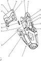
Fig. 1 in einer Explosionsdarstellung Bestandteile eines Vorderbackens einer erfindungsgemäßen Skibindung, -
Fig. 2 eine Draufsicht auf den Vorderbacken, -
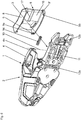
Fig. 3 eine Schrägansicht des Vorderbackens, -
Fig. 4 eine Seitenansicht des Vorderbackens, -
Fig. 5 eine Seitenansicht des Vorderbackens ohne Standplatte und -
Fig. 6 eine Unteransicht des Vorderbackens mit entfernter Standplatte. - In der nachfolgenden Beschreibung verwendete Begriffe wie "vorne", "rückwärtig", "vertikal" und "waagrecht" beziehen sich auf die Positionen der betreffenden Bauteile in den Darstellungen und auf eine am Ski für das Abfahren montierte Skibindung.
- Die Figuren zeigen einen Vorderbacken einer als alpine Abfahrtsskibindung ausgeführten Sicherheitsskibindung, deren zweiter Bindungsteil, ein Fersenbacken, auf herkömmliche Weise ausgeführt und in an sich bekannter Weise am nicht gezeigten Ski angeordnet sein kann.
- Der Vorderbacken 1 weist ein Gehäuse 2 mit einer Grundplatte 3 auf, mittels welcher der Vorderbacken 1 am Ski auf nicht gezeigte und an sich bekannte Weise angeordnet werden kann. Die Grundplatte 3 kann auch ein gesonderter Bauteil sein, welcher mit dem Gehäuse 2 fest verbunden, beispielsweise verschraubt, wird. Im Gehäuse 2 sind zwei Sohlenhalter 4 um vertikale Achsen bildenden Bolzen 5 drehbar angeordnet. Die Sohlenhalter 4, die bei der gezeigten Ausführungsform als Winkelhebel ausgebildet sind, wirken mit einem Auslösemechanismus zusammen, der eine Sicherheitsauslösung gewährleistet, und weisen Sohlenhalterarme 4a auf, die bei eingesetztem Skischuh den Sohlenrand zumindest von oben kontaktieren. Der Auslösemechanismus ist nicht Gegenstand der Erfindung, seine Bestandteile können in an sich bekannter Weise ausgeführt sein und sind daher Grossteils nicht dargestellt bzw. nicht gesondert bezeichnet.
- An der Grundplatte 3 ist eine in der Art einer Wippe bewegbare bzw. schwenkbare Standplatte 6 angeordnet. Wie insbesondere
Fig. 1 zeigt, weist die Oberseite der Standplatte 6 eine ebene und waagrechte Standfläche 7a auf, mit welcher der vordere Abschnitt einer Skischuhsohle flächig in Kontakt kommt. Bei der gezeigten Ausführungsform weist die Standplatte 6 ferner zwei Öffnungen auf, durch die hindurch eine Montage der Grundplatte 3 am Ski ermöglicht wird. An den Abschnitt 7a schließt nach vorne ein zweiter Abschnitt 7b an, welcher bei der gezeigten Ausführung eine gegenüber der Waagrechten unter einem Winkel α von etwa 5° bis 20° geneigte, insbesondere ebenfalls ebene Fläche ist, die nach vorne ansteigt. Die beiden Abschnitte 7a, 7b sind daher an die üblichen vorderen Endabschnitte von Skischuhsohlen angepasst, die an ihrer Spitze einen kurzen leicht nach oben gebogenen Abschnitt aufweisen, um das Gehen zu erleichtern. Die Standplatte 6 weist ferner zwei Seitenteile 8 auf, die bei montierter Standplatte 6 im Wesentlichen in Skilängsrichtung und senkrecht zur Standfläche 7 verlaufen. An den Innenseiten der Seitenteile 8 sind, wie insbesondereFig. 6 zeigt, jeweils ein vorderes Führungselement 9 und ein rückwärtiges Führungselement 9' ausgebildet. Die Führungselemente 9, 9' sind bei der gezeigten Ausführungsform kurze, nach innen weisende Vorsprünge der Seitenteile 8, die eine gewisse Längserstreckung aufweisen und an deren in Richtung zur Innenseite der Standfläche 7 orientierten Innenflächen Führungsbahnen 9a und 9b ausgebildet sind, die entlang von Abschnitten von Kreisbögen verlaufen. Die einem bestimmten Seitenteil 8 zugehörigen Führungsbahnen 9a und 9b befinden sich jeweils auf einem Kreis mit einem Radius von 30 mm bis 40 mm, die beiden Kreise der Führungsbahnen 9a, 9b jedes Seitenteils 8 weisen übereinstimmende Radien auf, die Mittelpunkte der Kreise befinden sich auf einer Achse 10, die quer zur Skilängsrichtung und parallel zur Skioberseite verläuft, wobei die Achse 10 die Drehachse für eine begrenzte Drehbeweglichkeit der Standplatte 6 bildet. Die Achse 10 verläuft vorzugsweise derart, dass sie die beiden Sohlenhalter 4 an deren am weitesten rückwärtig befindlichen Stellen berührt, die bei eingesetztem Skischuh mit dem oberen Rand der Schuhsohle in Kontakt kommen. Diese ideelle Achse 10 verbindet somit diese beiden Berührungspunkte an den Sohlenhaltern 4. Grundsätzlich sollte sich die Drehachse 10 im Bereich der rückwärtigen Endabschnitte der mit der Skischuhsohle in Kontakt kommenden Sohlenhalterarme 4a befinden, was ihre Lage in Skilängsrichtung betrifft. Was die Höhenlage, also die Lage relativ zur Skioberseite oder zur Standfläche 7 der Standplatte 6 betrifft, kann diese von der bevorzugten Lage, insbesondere um ± 1 cm, abweichen. Die Achse 10 kann daher auch unterhalb oder oberhalb der Sohlenhalterarme 4a verlaufen. Die relative Lage der Drehachse 10 zur Standplatte 6 sollte derart sein, dass bei einer Skidurchbiegung der vorderste leicht nach oben geneigte Spitzenabschnitt der Schuhsohle des in die Skibindung eingesetzten Skischuhs durch Kontakt mit dem Abschnitt 7b die Standplatte 6 gegen den Uhrzeigersinn um die Achse 10 kippen kann. Die Kontaktstelle der Skischuhsohle sollte sich daher vor der Drehachse 10 befinden. Diese Kontaktstelle kann eine Kontaktfläche zwischen dem vordersten nach oben geneigten Abschnitt der Schuhsohle und dem Abschnitt 7b sein, die Kontaktstelle kann auch linienförmig bzw. im Wesentlichen linienförmig -quer zur Skilängsrichtung verlaufend- sein. Dabei kann je nach der Neigung des Abschnittes 7b bei eingesetztem Skischuh noch kein Kontakt zwischen dem vordersten Abschnitt der Skischuhsohle und dem Standflächenabschnitt vorhanden sein, dieser stellt sich erst bei einer Skidurchbiegung ein. Bei einer alternativen Ausführungsform der Erfindung kann anstelle eines geneigten vorderen Abschnittes 7b auf der Oberseite der Standplatte 6 auch eine Rippe oder ein sonstiges Abstützelement ausgebildet oder angeordnet sein, welche bzw. welches mit der Skischuhsohle wie beschreiben zusammenwirkt. - Die an der Standplatte 6 ausgebildeten Führungsbahnen 9a und 9b wirken mit einem Paar vorderer Führungsbahnen 12a und einem Paar rückwärtiger Führungsbahnen 12b an Seitenteilen 11 der Grundplatte 3 zusammen. Wie insbesondere
Fig. 1 in Verbindung mitFig. 2 undFig. 3 zeigt, sind die Führungsbahnen 12a und 12b an der oberen Innenwand von Vertiefungen bzw. Ausnehmungen 11a der Seitenteile 11 der Grundplatte 3 ausgebildet, weisen Richtung Skioberseite und sind an jedem Seitenteil 11 Kreisbögen, deren Mittelpunkte sich auf der Achse 10 befinden. Bei auf der Grundplatte 3 positionierter Standplatte 6 greifen die Führungselemente 9 und 9' in die Vertiefungen 11a der Seitenteile 11, sodass die Führungsbahnen 9a, 9b in Kontakt mit den Führungsbahnen 12a, 12b sind. Auf diese Weise ist die Standplatte 6 an der Grundplatte 3 gegen ein Abheben in vertikaler Richtung gehalten und gegenüber der Grundplatte 3 um die Achse 10 als Drehachse um einen gewissen Winkelbereich, insbesondere um bis zu 10°, drehbar, wobei die Ausgangslage die vordere Endstellung der Standplatte 6 ist. Die vordere Endstellung der Standplatte 6 wird bei der gezeigten Ausführung durch Anschlagflächen 13 und 16 an der Grundplatte 3 und der Innenseite der Standplatte 6 bestimmt, die in der normalen Betriebsstellung miteinander flächig in Kontakt kommen und daher in dieser Lage eine Drehbewegung der Standplatte 6 relativ zur Grundplatte 3 im Uhrzeigersinn unterbinden. Die Standplatte 6 wird zusätzlich unter der Wirkung eines Federelementes nach vorne gedrückt. Bei der gezeigten Ausführungsform ist eine Druckfeder 14 vorgesehen, die sowohl in einer sich in Längsrichtung der Grundplatte 3 erstreckenden Vertiefung 15 als auch in einer Vertiefung 17 an der Innenseite der Standplatte 6 eingesetzt ist, mit ihrem einen Ende an der Grundplatte 3 und mit ihrem anderen Ende an der Standplatte 6 abgestützt ist. - Die mit der Erfindung ermöglichte wippenartige Drehbeweglichkeit der Standplatte 6 stellt sicher, dass ein flächiger Kontakt der Skischuhsohle am Abschnitt 7a der Standfläche 7 der Standplatte 6 auch bei einer Skidurchbiegung erhalten bleibt, da bei einer Skidurchbiegung die Standplatte 6 durch den Skischuh gegen den Uhrzeigersinn verschwenkt wird. Bei einer Skidurchbiegung bleibt daher eine gute Kraftübertragung vom Skischuh auf den Vorderbacken 1, auch bei stark aufgekanteten Skiern, gewährleistet, insbesondere, wenn durch die Wahl der Lage der Achse 10 der Abstand der Sohlenhalter 4 zur Standplatte 6 bei Skidurchbiegung zumindest im Wesentlichen konstant bleiben kann.
- Bei einer nicht dargestellten Ausführungsform ist es möglich, die Führungselemente an der Standplatte 6 als kurze Führungsbolzen auszuführen, die an den Seitenteilen nach innen ragen und, wie beschrieben, mit den Führungsbahnen an der Grundplatte zusammenwirken. Des Weiteren kann die Federbeaufschlagung der Standplatte durch eine Blattfeder oder eine Zugfeder oder ein sonstiges federndes Element erfolgen. Die Erfindung ist ferner auch bei Vorderbacken anwendbar, die einen einzigen um eine zentrale Hochachse nach beiden Seiten drehbaren Sohlenhalter aufweisen. Des Weiteren kann jeweils an der Grundplatte und der Sohlenplatte nur ein Paar von Führungsbahnen und Führungselementen ausgebildet sein. Möglich ist auch eine Ausführungsform, bei der, insbesondere mittig an der Grundplatte, eine einzige Führungsbahn vorgesehen ist, die mit einem einzigen Führungselement an der Standplatte entsprechend zusammenwirkt.
-
- 1
- Vorderbacken
- 2
- Gehäuse
- 3
- Grundplatte
- 4
- Sohlenhalter
- 4a
- Sohlenhalterarme
- 5
- Bolzen
- 6
- Standplatte
- 7
- Standfläche
- 7a
- Abschnitt
- 7b
- Abschnitt
- 8
- Seitenteil
- 9, 9'
- Führungselement
- 9a, 9b
- Führungsbahn
- 10
- Achse
- 11
- Seitenteil
- 11a
- Vertiefung
- 12a
- Führungsbahn
- 12b
- Führungsbahn
- 13
- Anschlagfläche
- 14
- Druckfeder
- 15
- Vertiefung
- 16
- Anschlagfläche
- 17
- Vertiefung
Claims (13)
- Vorderbacken (1) für eine Sicherheitsskibindung, welcher mit einem einen Auslösemechanismus aufnehmenden Gehäuse (2), zumindest einem Paar von Sohlenhalterarmen (4a), welche den vorderen Endbereich des Sohlenrandes eines Skischuhs erfassen können, und mit einer Grundplatte (3) versehen ist, auf welcher eine Standplatte (6) zur Auflage des vorderen Abschnittes einer Skischuhsohle angeordnet ist,
dadurch gekennzeichnet,
dass die Standplatte (6) an der Grundplatte (3) entlang einer in Skilängsrichtung bezüglich der Skioberseite konkav gekrümmten Bahn um eine ideelle Drehachse (10) begrenzt drehbar ist, welche sich im Bereich der Sohlenhalterarme (4a) befindet. - Vorderbacken (1) nach Anspruch 1, dadurch gekennzeichnet, dass die Bahn kreisbogenförmig gekrümmt ist.
- Vorderbacken (1) nach Anspruch 1, dadurch gekennzeichnet, dass die Standplatte (6) in ihrem vorderen Abschnitt (7b) erhöht ist und eine vor der Drehachse (10) positionierte Kontaktstelle für den vordersten Abschnitt der Skischuhsohle bildet bzw. zur Verfügung stellt.
- Vorderbacken (1) nach einem der Ansprüche 1 bis 3, dadurch gekennzeichnet, dass der vorderer Abschnitt (7b) der Standplatte (7) nach vorne ansteigend verläuft.
- Vorderbacken (1) nach einem der Ansprüche 1 bis 4, dadurch gekennzeichnet, dass die Bahn zur beweglichen Anordnung der Standplatte (6) an der Grundplatte (3) von zumindest einer an dem einen Bauteil vorgesehenen Führungsbahn (12a, 12b) gebildet ist, entlang welcher ein am anderen Bauteil vorgesehenes Führungselement (9, 9') geführt ist.
- Vorderbacken (1) nach einem der Ansprüche 1 bis 5, dadurch gekennzeichnet, dass an jeder Seite der Grundplatte (3) zumindest eine kreisbogenförmige Führungsbahn (12a, 12b) an der der Skioberseite zugewandten Innenseite einer Vertiefung (15) ausgebildet ist, wobei mit jeder Führungsbahn (12, 12b) ein an der Standplatte (6) ausgebildetes Führungselement (9, 9') in Kontakt ist.
- Vorderbacken (1) nach Anspruch 6, dadurch gekennzeichnet, dass die an der Standplatte (6) vorgesehenen Führungselemente (9, 9') ebenfalls kreisbogenförmige Führungsbahnen (9a, 9b) aufweisen.
- Vorderbacken (1) nach Anspruch 6 oder 7, dadurch gekennzeichnet, dass die an der Standplatte (6) vorgesehenen Führungselemente (9, 9') Bolzen, Zapfen oder dergleichen sind.
- Vorderbacken (1) nach einem der Ansprüche 1 bis 8, dadurch gekennzeichnet, dass der Drehradius der Standplatte (6) 30 mm bis 40 mm beträgt.
- Vorderbacken (1) nach Anspruch 1 oder 3, dadurch gekennzeichnet, dass die Drehachse (10) im Bereich der am Weitesten rückwärtig befindlichen Kontaktstellen des Sohlenrandes eines eingesetzten Skischuhs mit den Sohlenhalterarmen (4a) verläuft.
- Vorderbacken (1) nach einem der Ansprüche 1 bis 10, dadurch gekennzeichnet, dass die Standplatte (6) unter der Wirkung zumindest eines Federelementes in ihre Normalstellung gedrückt wird.
- Vorderbacken (1) nach Anspruch 11, dadurch gekennzeichnet, dass das Federelement das Ausmaß der Beweglichkeit der Standplatte (6) gegenüber der Grundplatte (3) begrenzt.
- Vorderbacken (1) nach Anspruch 11 oder 12, dadurch gekennzeichnet, dass das Federelement zwischen der Grundplatte (3) und der Standplatte (6) eingebaut und an diesen beiden Teilen abgestützt ist.
Applications Claiming Priority (1)
| Application Number | Priority Date | Filing Date | Title |
|---|---|---|---|
| ATA50111/2014A AT515397B1 (de) | 2014-02-13 | 2014-02-13 | Vorderbacken einer Sicherheitsskibindung |
Publications (2)
| Publication Number | Publication Date |
|---|---|
| EP2907556A1 EP2907556A1 (de) | 2015-08-19 |
| EP2907556B1 true EP2907556B1 (de) | 2017-08-30 |
Family
ID=52464193
Family Applications (1)
| Application Number | Title | Priority Date | Filing Date |
|---|---|---|---|
| EP15153604.2A Active EP2907556B1 (de) | 2014-02-13 | 2015-02-03 | Vorderbacken einer Sicherheitsskibindung |
Country Status (2)
| Country | Link |
|---|---|
| EP (1) | EP2907556B1 (de) |
| AT (1) | AT515397B1 (de) |
Family Cites Families (7)
| Publication number | Priority date | Publication date | Assignee | Title |
|---|---|---|---|---|
| US2172669A (en) * | 1939-09-12 | Ski harness | ||
| FR2739301B1 (fr) * | 1995-09-28 | 1997-12-12 | Salomon Sa | Element et ensemble de retenue d'une chaussure sur une planche de glisse |
| DE10004914B4 (de) | 2000-02-04 | 2005-02-03 | Marker Deutschland Gmbh | Abstützung einer biegesteifen Stand- bzw. Sohlenplatte auf einem Ski |
| FR2815547B1 (fr) * | 2000-10-24 | 2003-02-07 | Salomon Sa | Dispositif interface entre un ski et des elements de retenue d'une chaussure sur un ski |
| DE502006007529D1 (de) * | 2006-05-12 | 2010-09-09 | Fritschi Ag Swiss Bindings | Skibindung |
| DE102009018853A1 (de) * | 2009-04-24 | 2010-10-28 | Marker Deutschland Gmbh | Skibindung |
| AT510021B1 (de) * | 2010-09-17 | 2012-01-15 | Tyrolia Technology Gmbh | Sohlenauflageplatte und skibindung mit einer sohlenauflageplatte |
-
2014
- 2014-02-13 AT ATA50111/2014A patent/AT515397B1/de not_active IP Right Cessation
-
2015
- 2015-02-03 EP EP15153604.2A patent/EP2907556B1/de active Active
Non-Patent Citations (1)
| Title |
|---|
| None * |
Also Published As
| Publication number | Publication date |
|---|---|
| EP2907556A1 (de) | 2015-08-19 |
| AT515397B1 (de) | 2015-11-15 |
| AT515397A1 (de) | 2015-08-15 |
Similar Documents
| Publication | Publication Date | Title |
|---|---|---|
| DE202011110813U1 (de) | Fersenautomat | |
| DE102012201812B4 (de) | Vordereinheit für eine Gleitbrettbindung, Tourenbindung und Skisprungbindung | |
| DE2849359A1 (de) | Sicherheitsskibindung | |
| EP3928842B1 (de) | Vordereinheit für eine tourenbindung | |
| DE102012208915A1 (de) | Ferseneinheit mit Steighilfe und Bremsanordnung | |
| DE102011082612A1 (de) | Ferseneinheit für eine Tourenbindung | |
| EP3554656B1 (de) | Langlauf- oder tourenskibindung | |
| EP3120903B1 (de) | Fersenautomat | |
| EP0320854B1 (de) | Vorderbacken einer Sicherheitsskibindung | |
| EP3345659B1 (de) | Fersenautomat für eine skibindung | |
| DE3939634C2 (de) | Sicherheitsskibindung zum Halten des vorderen Endes eines auf dem Ski montierten Schuhs | |
| EP3167943B1 (de) | Fersenautomat mit fersenabstützstruktur | |
| DE10255499A1 (de) | Auslösbare Skibindung | |
| AT515397B1 (de) | Vorderbacken einer Sicherheitsskibindung | |
| DE2364298A1 (de) | Ausloese-haltevorrichtung fuer sicherheitsskibindungen | |
| DE69705804T2 (de) | Abstützungsplatte für Schuhe auf Skis | |
| EP0394380B1 (de) | Sicherheitsskibindung | |
| EP3117881A1 (de) | Vorderbacken einer sicherheitsskibindung | |
| EP3135351B1 (de) | Vorderbacken einer sicherheitsskibindung | |
| EP1022037A1 (de) | Telemark-Skibindung | |
| DE2637871A1 (de) | Sicherheitsskibindung | |
| AT526522B1 (de) | Vorderbacken und Sicherheitsskibindung mit einem Vorderbacken | |
| EP0408824A2 (de) | Skistiefel-Sicherheitsskibindungsanordnung | |
| DE2550459A1 (de) | Lageranordnung fuer die trittplatte oder den drehteller von ausloesenden skibindungen | |
| DE69720318T2 (de) | Vorderbackensystem für Schuhe auf Skis |
Legal Events
| Date | Code | Title | Description |
|---|---|---|---|
| PUAI | Public reference made under article 153(3) epc to a published international application that has entered the european phase |
Free format text: ORIGINAL CODE: 0009012 |
|
| AK | Designated contracting states |
Kind code of ref document: A1 Designated state(s): AL AT BE BG CH CY CZ DE DK EE ES FI FR GB GR HR HU IE IS IT LI LT LU LV MC MK MT NL NO PL PT RO RS SE SI SK SM TR |
|
| AX | Request for extension of the european patent |
Extension state: BA ME |
|
| 17P | Request for examination filed |
Effective date: 20160212 |
|
| RBV | Designated contracting states (corrected) |
Designated state(s): AL AT BE BG CH CY CZ DE DK EE ES FI FR GB GR HR HU IE IS IT LI LT LU LV MC MK MT NL NO PL PT RO RS SE SI SK SM TR |
|
| GRAP | Despatch of communication of intention to grant a patent |
Free format text: ORIGINAL CODE: EPIDOSNIGR1 |
|
| INTG | Intention to grant announced |
Effective date: 20170412 |
|
| GRAS | Grant fee paid |
Free format text: ORIGINAL CODE: EPIDOSNIGR3 |
|
| GRAA | (expected) grant |
Free format text: ORIGINAL CODE: 0009210 |
|
| AK | Designated contracting states |
Kind code of ref document: B1 Designated state(s): AL AT BE BG CH CY CZ DE DK EE ES FI FR GB GR HR HU IE IS IT LI LT LU LV MC MK MT NL NO PL PT RO RS SE SI SK SM TR |
|
| REG | Reference to a national code |
Ref country code: GB Ref legal event code: FG4D Free format text: NOT ENGLISH |
|
| REG | Reference to a national code |
Ref country code: CH Ref legal event code: EP |
|
| REG | Reference to a national code |
Ref country code: AT Ref legal event code: REF Ref document number: 922985 Country of ref document: AT Kind code of ref document: T Effective date: 20170915 |
|
| REG | Reference to a national code |
Ref country code: IE Ref legal event code: FG4D Free format text: LANGUAGE OF EP DOCUMENT: GERMAN |
|
| REG | Reference to a national code |
Ref country code: DE Ref legal event code: R096 Ref document number: 502015001758 Country of ref document: DE |
|
| REG | Reference to a national code |
Ref country code: NL Ref legal event code: MP Effective date: 20170830 |
|
| REG | Reference to a national code |
Ref country code: LT Ref legal event code: MG4D |
|
| PG25 | Lapsed in a contracting state [announced via postgrant information from national office to epo] |
Ref country code: SE Free format text: LAPSE BECAUSE OF FAILURE TO SUBMIT A TRANSLATION OF THE DESCRIPTION OR TO PAY THE FEE WITHIN THE PRESCRIBED TIME-LIMIT Effective date: 20170830 Ref country code: FI Free format text: LAPSE BECAUSE OF FAILURE TO SUBMIT A TRANSLATION OF THE DESCRIPTION OR TO PAY THE FEE WITHIN THE PRESCRIBED TIME-LIMIT Effective date: 20170830 Ref country code: LT Free format text: LAPSE BECAUSE OF FAILURE TO SUBMIT A TRANSLATION OF THE DESCRIPTION OR TO PAY THE FEE WITHIN THE PRESCRIBED TIME-LIMIT Effective date: 20170830 Ref country code: HR Free format text: LAPSE BECAUSE OF FAILURE TO SUBMIT A TRANSLATION OF THE DESCRIPTION OR TO PAY THE FEE WITHIN THE PRESCRIBED TIME-LIMIT Effective date: 20170830 Ref country code: NO Free format text: LAPSE BECAUSE OF FAILURE TO SUBMIT A TRANSLATION OF THE DESCRIPTION OR TO PAY THE FEE WITHIN THE PRESCRIBED TIME-LIMIT Effective date: 20171130 |
|
| REG | Reference to a national code |
Ref country code: FR Ref legal event code: PLFP Year of fee payment: 4 |
|
| PG25 | Lapsed in a contracting state [announced via postgrant information from national office to epo] |
Ref country code: LV Free format text: LAPSE BECAUSE OF FAILURE TO SUBMIT A TRANSLATION OF THE DESCRIPTION OR TO PAY THE FEE WITHIN THE PRESCRIBED TIME-LIMIT Effective date: 20170830 Ref country code: RS Free format text: LAPSE BECAUSE OF FAILURE TO SUBMIT A TRANSLATION OF THE DESCRIPTION OR TO PAY THE FEE WITHIN THE PRESCRIBED TIME-LIMIT Effective date: 20170830 Ref country code: IS Free format text: LAPSE BECAUSE OF FAILURE TO SUBMIT A TRANSLATION OF THE DESCRIPTION OR TO PAY THE FEE WITHIN THE PRESCRIBED TIME-LIMIT Effective date: 20171230 Ref country code: GR Free format text: LAPSE BECAUSE OF FAILURE TO SUBMIT A TRANSLATION OF THE DESCRIPTION OR TO PAY THE FEE WITHIN THE PRESCRIBED TIME-LIMIT Effective date: 20171201 Ref country code: ES Free format text: LAPSE BECAUSE OF FAILURE TO SUBMIT A TRANSLATION OF THE DESCRIPTION OR TO PAY THE FEE WITHIN THE PRESCRIBED TIME-LIMIT Effective date: 20170830 Ref country code: BG Free format text: LAPSE BECAUSE OF FAILURE TO SUBMIT A TRANSLATION OF THE DESCRIPTION OR TO PAY THE FEE WITHIN THE PRESCRIBED TIME-LIMIT Effective date: 20171130 |
|
| PG25 | Lapsed in a contracting state [announced via postgrant information from national office to epo] |
Ref country code: NL Free format text: LAPSE BECAUSE OF FAILURE TO SUBMIT A TRANSLATION OF THE DESCRIPTION OR TO PAY THE FEE WITHIN THE PRESCRIBED TIME-LIMIT Effective date: 20170830 |
|
| PG25 | Lapsed in a contracting state [announced via postgrant information from national office to epo] |
Ref country code: DK Free format text: LAPSE BECAUSE OF FAILURE TO SUBMIT A TRANSLATION OF THE DESCRIPTION OR TO PAY THE FEE WITHIN THE PRESCRIBED TIME-LIMIT Effective date: 20170830 Ref country code: RO Free format text: LAPSE BECAUSE OF FAILURE TO SUBMIT A TRANSLATION OF THE DESCRIPTION OR TO PAY THE FEE WITHIN THE PRESCRIBED TIME-LIMIT Effective date: 20170830 Ref country code: PL Free format text: LAPSE BECAUSE OF FAILURE TO SUBMIT A TRANSLATION OF THE DESCRIPTION OR TO PAY THE FEE WITHIN THE PRESCRIBED TIME-LIMIT Effective date: 20170830 Ref country code: CZ Free format text: LAPSE BECAUSE OF FAILURE TO SUBMIT A TRANSLATION OF THE DESCRIPTION OR TO PAY THE FEE WITHIN THE PRESCRIBED TIME-LIMIT Effective date: 20170830 |
|
| PG25 | Lapsed in a contracting state [announced via postgrant information from national office to epo] |
Ref country code: EE Free format text: LAPSE BECAUSE OF FAILURE TO SUBMIT A TRANSLATION OF THE DESCRIPTION OR TO PAY THE FEE WITHIN THE PRESCRIBED TIME-LIMIT Effective date: 20170830 Ref country code: SK Free format text: LAPSE BECAUSE OF FAILURE TO SUBMIT A TRANSLATION OF THE DESCRIPTION OR TO PAY THE FEE WITHIN THE PRESCRIBED TIME-LIMIT Effective date: 20170830 Ref country code: SM Free format text: LAPSE BECAUSE OF FAILURE TO SUBMIT A TRANSLATION OF THE DESCRIPTION OR TO PAY THE FEE WITHIN THE PRESCRIBED TIME-LIMIT Effective date: 20170830 |
|
| REG | Reference to a national code |
Ref country code: DE Ref legal event code: R097 Ref document number: 502015001758 Country of ref document: DE |
|
| PLBE | No opposition filed within time limit |
Free format text: ORIGINAL CODE: 0009261 |
|
| STAA | Information on the status of an ep patent application or granted ep patent |
Free format text: STATUS: NO OPPOSITION FILED WITHIN TIME LIMIT |
|
| 26N | No opposition filed |
Effective date: 20180531 |
|
| PG25 | Lapsed in a contracting state [announced via postgrant information from national office to epo] |
Ref country code: SI Free format text: LAPSE BECAUSE OF FAILURE TO SUBMIT A TRANSLATION OF THE DESCRIPTION OR TO PAY THE FEE WITHIN THE PRESCRIBED TIME-LIMIT Effective date: 20170830 |
|
| PG25 | Lapsed in a contracting state [announced via postgrant information from national office to epo] |
Ref country code: MT Free format text: LAPSE BECAUSE OF FAILURE TO SUBMIT A TRANSLATION OF THE DESCRIPTION OR TO PAY THE FEE WITHIN THE PRESCRIBED TIME-LIMIT Effective date: 20170830 Ref country code: MC Free format text: LAPSE BECAUSE OF FAILURE TO SUBMIT A TRANSLATION OF THE DESCRIPTION OR TO PAY THE FEE WITHIN THE PRESCRIBED TIME-LIMIT Effective date: 20170830 |
|
| REG | Reference to a national code |
Ref country code: IE Ref legal event code: MM4A |
|
| REG | Reference to a national code |
Ref country code: BE Ref legal event code: MM Effective date: 20180228 |
|
| PG25 | Lapsed in a contracting state [announced via postgrant information from national office to epo] |
Ref country code: LU Free format text: LAPSE BECAUSE OF NON-PAYMENT OF DUE FEES Effective date: 20180203 |
|
| PG25 | Lapsed in a contracting state [announced via postgrant information from national office to epo] |
Ref country code: IE Free format text: LAPSE BECAUSE OF NON-PAYMENT OF DUE FEES Effective date: 20180203 |
|
| PG25 | Lapsed in a contracting state [announced via postgrant information from national office to epo] |
Ref country code: BE Free format text: LAPSE BECAUSE OF NON-PAYMENT OF DUE FEES Effective date: 20180228 |
|
| GBPC | Gb: european patent ceased through non-payment of renewal fee |
Effective date: 20190203 |
|
| PG25 | Lapsed in a contracting state [announced via postgrant information from national office to epo] |
Ref country code: GB Free format text: LAPSE BECAUSE OF NON-PAYMENT OF DUE FEES Effective date: 20190203 |
|
| PG25 | Lapsed in a contracting state [announced via postgrant information from national office to epo] |
Ref country code: TR Free format text: LAPSE BECAUSE OF FAILURE TO SUBMIT A TRANSLATION OF THE DESCRIPTION OR TO PAY THE FEE WITHIN THE PRESCRIBED TIME-LIMIT Effective date: 20170830 |
|
| PG25 | Lapsed in a contracting state [announced via postgrant information from national office to epo] |
Ref country code: PT Free format text: LAPSE BECAUSE OF FAILURE TO SUBMIT A TRANSLATION OF THE DESCRIPTION OR TO PAY THE FEE WITHIN THE PRESCRIBED TIME-LIMIT Effective date: 20170830 |
|
| PG25 | Lapsed in a contracting state [announced via postgrant information from national office to epo] |
Ref country code: CY Free format text: LAPSE BECAUSE OF FAILURE TO SUBMIT A TRANSLATION OF THE DESCRIPTION OR TO PAY THE FEE WITHIN THE PRESCRIBED TIME-LIMIT Effective date: 20170830 Ref country code: MK Free format text: LAPSE BECAUSE OF NON-PAYMENT OF DUE FEES Effective date: 20170830 Ref country code: HU Free format text: LAPSE BECAUSE OF FAILURE TO SUBMIT A TRANSLATION OF THE DESCRIPTION OR TO PAY THE FEE WITHIN THE PRESCRIBED TIME-LIMIT; INVALID AB INITIO Effective date: 20150203 |
|
| PG25 | Lapsed in a contracting state [announced via postgrant information from national office to epo] |
Ref country code: AL Free format text: LAPSE BECAUSE OF FAILURE TO SUBMIT A TRANSLATION OF THE DESCRIPTION OR TO PAY THE FEE WITHIN THE PRESCRIBED TIME-LIMIT Effective date: 20170830 |
|
| REG | Reference to a national code |
Ref country code: CH Ref legal event code: U11 Free format text: ST27 STATUS EVENT CODE: U-0-0-U10-U11 (AS PROVIDED BY THE NATIONAL OFFICE) Effective date: 20260301 |
|
| PGFP | Annual fee paid to national office [announced via postgrant information from national office to epo] |
Ref country code: DE Payment date: 20260218 Year of fee payment: 12 |
|
| PGFP | Annual fee paid to national office [announced via postgrant information from national office to epo] |
Ref country code: AT Payment date: 20260219 Year of fee payment: 12 |
|
| PGFP | Annual fee paid to national office [announced via postgrant information from national office to epo] |
Ref country code: IT Payment date: 20260224 Year of fee payment: 12 |
|
| PGFP | Annual fee paid to national office [announced via postgrant information from national office to epo] |
Ref country code: FR Payment date: 20260218 Year of fee payment: 12 |
|
| PGFP | Annual fee paid to national office [announced via postgrant information from national office to epo] |
Ref country code: CH Payment date: 20260301 Year of fee payment: 12 |