EP2907375A1 - Eine Bewässerungseinrichtung für die kontrollierte Freisetzung einer Flüssigkeit - Google Patents
Eine Bewässerungseinrichtung für die kontrollierte Freisetzung einer Flüssigkeit Download PDFInfo
- Publication number
- EP2907375A1 EP2907375A1 EP14199156.2A EP14199156A EP2907375A1 EP 2907375 A1 EP2907375 A1 EP 2907375A1 EP 14199156 A EP14199156 A EP 14199156A EP 2907375 A1 EP2907375 A1 EP 2907375A1
- Authority
- EP
- European Patent Office
- Prior art keywords
- irrigation device
- stabilizing
- stabilizing flange
- elongated body
- respect
- Prior art date
- Legal status (The legal status is an assumption and is not a legal conclusion. Google has not performed a legal analysis and makes no representation as to the accuracy of the status listed.)
- Withdrawn
Links
- 230000002262 irrigation Effects 0.000 title claims abstract description 67
- 238000003973 irrigation Methods 0.000 title claims abstract description 67
- 239000007788 liquid Substances 0.000 title claims abstract description 17
- 238000013270 controlled release Methods 0.000 title claims abstract description 12
- 230000000087 stabilizing effect Effects 0.000 claims abstract description 144
- 238000004891 communication Methods 0.000 claims abstract description 3
- 239000012530 fluid Substances 0.000 claims abstract description 3
- 230000003313 weakening effect Effects 0.000 claims description 19
- 230000008878 coupling Effects 0.000 claims description 16
- 238000010168 coupling process Methods 0.000 claims description 16
- 238000005859 coupling reaction Methods 0.000 claims description 16
- 230000000670 limiting effect Effects 0.000 claims description 16
- 230000000295 complement effect Effects 0.000 claims description 10
- 230000002441 reversible effect Effects 0.000 claims description 8
- 230000008859 change Effects 0.000 claims description 5
- 230000002427 irreversible effect Effects 0.000 claims description 4
- 238000003780 insertion Methods 0.000 claims description 3
- 230000037431 insertion Effects 0.000 claims description 3
- 230000001419 dependent effect Effects 0.000 claims 3
- 239000003381 stabilizer Substances 0.000 claims 1
- 230000000284 resting effect Effects 0.000 description 5
- 230000007423 decrease Effects 0.000 description 3
- 230000005484 gravity Effects 0.000 description 3
- 238000000034 method Methods 0.000 description 3
- 230000009471 action Effects 0.000 description 1
- 230000008901 benefit Effects 0.000 description 1
- 230000003247 decreasing effect Effects 0.000 description 1
- 230000000694 effects Effects 0.000 description 1
- 238000009434 installation Methods 0.000 description 1
- 238000004519 manufacturing process Methods 0.000 description 1
- 239000000203 mixture Substances 0.000 description 1
- 230000008439 repair process Effects 0.000 description 1
- 238000000926 separation method Methods 0.000 description 1
- 230000006641 stabilisation Effects 0.000 description 1
- 238000011105 stabilization Methods 0.000 description 1
Images


Classifications
-
- A—HUMAN NECESSITIES
- A01—AGRICULTURE; FORESTRY; ANIMAL HUSBANDRY; HUNTING; TRAPPING; FISHING
- A01G—HORTICULTURE; CULTIVATION OF VEGETABLES, FLOWERS, RICE, FRUIT, VINES, HOPS OR SEAWEED; FORESTRY; WATERING
- A01G27/00—Self-acting watering devices, e.g. for flower-pots
- A01G27/006—Reservoirs, separate from plant-pots, dispensing directly into rooting medium
Definitions
- the object of the present invention is an irrigation device for the controlled release of a liquid towards the ground and coming from any container.
- the object of the present invention is constituted by an irrigation device with improved stability, for example suitable for use in pots or containers.
- said devices have connecting means on one end for connection with the neck of a bottle, and a wedge on the other end, by means of which they can be set into the ground. It is important that such devices are positioned perpendicularly to the ground, which often coincides with the force of gravity, and that they remain aligned with the same perpendicular in the course of operation, as possible inclination of the device-container system with respect to gravity and/or the ground could make the dripping procedure inefficient.
- External agents such as gusts of wind or landslides or other external causes can trigger rotation of the above-mentioned system, which is further magnified owing to the heavy weight of the container, particularly if the latter is full of liquid.
- Rotation of the device can be due for example to instability of the equilibrium position of the mass of the container, - the mass can tend to magnify even very small misalignments between the direction of gravity and the axis of the container - or to other external causes such as relative movements of the ground.
- the possibility that the device will rotate increases as the length of the wedge to be inserted in the ground decreases, in that the resistance that the ground opposes to rotation of the device is directly proportional to the surface area of contact with the wedge and to its extension in depth, which increases with the relative length thereof. With decreasing depth of the ground below the irrigation device, particularly in the case of small pots, resistance to possible rotation of the device can decrease significantly.
- Irrigation devices for the controlled release of a liquid do not currently provide measures hindering and possibly preventing the inclination thereof with respect to the ground once they have been set therein.
- One objective of the present invention is to provide an irrigation device for the controlled release of a liquid that is stable on the ground and thus capable of preventing rotation, tilting with respect to the vertical, once the same device has been set into the ground or in any case, fixed with respect to the ground.
- a further objective of the present invention is to provide an irrigation device that is simple, economical and unlikely to undergo wear and tear.
- an irrigation device comprising a stabilizing flange defining a planar stabilizing surface that extends perpendicularly to the longitudinal axis of the elongated body of the irrigation device away from the elongated body itself and that is configured to be rested on the ground to be irrigated, in which the stabilizing flange delimits the irrigation portion with respect to the longitudinal axis of the elongated body.
- the irrigation portion that is, the portion designed to be inserted in the ground, is properly and unequivocally defined, and together with the presence of the stabilizing surface, it effectively makes it possible to prevent inclination of the device, even when the weight is a high owing to the mass of the liquid present therein.
- the use of the stabilizing flange makes it possible to realize a structure that is unlikely to undergo wear and tear and that is simple in that it is constituted mainly by the elongated body and the stabilizing flange.
- the present invention concerns a stabilizing flange for an irrigation device for the controlled release of a liquid and suitable for being partially inserted into the ground to be irrigated.
- the stabilizing flange comprises coupling means for coupling with an elongated body of the irrigation device and it defines a planar stabilizing surface suitable for extension perpendicularly to a longitudinal axis of the elongated body away from the elongated body itself and that is configured to be rested on the ground to be irrigated.
- One or more of the following characteristics can be comprised in one or more of the aspects indicated above.
- the stabilizing flange preferably comprises a central portion, which is proximal with respect to the longitudinal axis, and at least three projecting portions projecting from the central portion away from the longitudinal axis and preferably distributed uniformly with respect to the longitudinal axis.
- This configuration and distribution enable stable support in at least three portions distributed around the longitudinal axis.
- the support is further improved in the case in which the three projecting portions are uniformly distributed around the longitudinal axis, for example at about 120° with respect to each other.
- the stabilizing flange comprises means for varying geometry configured to change the planar stabilizing surface from an extended configuration to a contained configuration and/or vice versa.
- the means for varying geometry is intended as at least one means that is suitable for varying the geometry, and preferably suitable for varying the extension and the plan dimensions of the stabilizing flange.
- the means for varying geometry can operate in a reversible manner or in an irreversible manner.
- the means for varying geometry comprises at least a first part of the stabilizing flange that is detachable from at least a second part of the stabilizing flange.
- the means for varying geometry preferably comprises a weakening line interposed between the first part and the second part and configured so as to facilitate detachment of the first part from the second part.
- At least a first part of the stabilizing flange can be at least partially detached at least from a second part of the stabilizing flange, for example by means of a removable connection that allows for removal of the first part and for subsequent and thus reversible reattachment, or as a line of weakening that enables convenient separation of the first part from the second part definitively, and thus irreversibly, unless repairs are made.
- the means for varying geometry comprises at least a first part of the stabilizing flange that is suitable for being moved with respect to at least a second part of the stabilizing flange, so as to pass at least from a first position, in which the first and second parts are substantially aligned so as to form said planar stabilizing surface, to a second position, in which the planar stabilizing surface is substantially defined by the second part.
- the first part of the stabilizing flange is suitable for being rotated with respect to the second part of the stabilizing flange so as to pass at least from the first position to the second position, in which the first and second parts are inclined with respect to each other.
- the first part of the stabilizing flange is suitable for being moved with respect to the second part of the stabilizing flange by means of at least one rigid motion, preferably a rigid rotation.
- the means for varying geometry preferably comprises a hinge.
- At least a first part of the stabilizing flange can be moved with respect to at least a second part of the stabilizing flange by means of at least one rigid motion, as could be the case of a hinge that makes it possible to rigidly rotate for example a projecting portion of the stabilizing flange with respect to a central portion thereof and then reversibly have it return to the starting position.
- the stabilizing flange is suitable for being moved, preferably rotated, with respect to the second part of the stabilizing flange by means of at least one deformation of a portion of the stabilizing flange.
- the means for varying geometry preferably comprises a line of weakening interposed between the first part and the second part, in which the line of weakening is configured so as to facilitate the rotation of the first part with respect to the second part.
- At least a first part of the stabilizing flange can be moved with respect to at least a second part of the stabilizing flange by means of at least a deformation, which could be a line of weakening that enables the stabilizing flange to be bent by moving for example a projecting portion thereof with respect to a central portion thereof.
- a limiting means configured so as to limit at least partially and along at least one direction, the movement, preferably the rotation, of the first part with respect to the second part.
- the limiting means provides the stabilizing flange with resistance to rotation, when the stabilizing flange is in the most extended configuration, a resistance that is substantially similar to the resistance that would be obtained if the means for varying geometry were not present. This makes it possible to avoid the occurrence of a possible drawback such that when the stabilizing flange tends to tilt on the ground, the part on which the greatest pressure is exerted is not capable of opposing the rotation of the irrigation device given that the first part is raised with respect to second part.
- the limiting means is preferably configured so as to keep the first part in the first position during insertion of the elongated body into the ground and/or in the case of inclination of the stabilizing flange on the ground.
- the limiting means preferably comprises at least one abutment portion of the first part that is suitable for overlapping at least partially the second part in the first position.
- the abutment portion limits at least partially and at least in one direction, the rotation of the first part abutting against the second part.
- at least one seat at least partially complementary to the abutment portion is afforded in the second part and the seat is configured so as to receive the abutment portion in the first position of the first part.
- the seat opens at least partially along a surface of the stabilizing flange, opposite the planar stabilizing surface. The presence of an abutment surface makes the resistance of the stabilizing flange substantially similar to that of a stabilizing flange that is not equipped with movable parts.
- the first and second parts are substantially aligned in the first position.
- the means for varying geometry is configured so as to define a second position of the first part, in which the first part is suitable for being wedged into the ground. In this manner, it is possible to obtain an additional stabilizing effect that cooperates with the presence of the stabilizing surface.
- each projecting portion comprises a first part that is detachable from at least a second part of the projecting portion and/or of said central portion.
- each projecting portion comprises a first part that is movable with respect to at least a second part of the projecting portion and/or of the central portion.
- the first part of the stabilizing flange can consist of a part of the projecting portion or the entire projecting portion. In the case of a number of projecting portions projecting from a central portion, the central portion defines the second part of the stabilizing flange for all the projecting portions.
- the edge of at least one projecting portion is at least partly curved in shape and at least two consecutive projecting portions are connected by a curved line, the convexity of which faces the longitudinal axis.
- This shape enables convenient installation even in tight or in any case, rather small spaces, including for example near the structural parts of a pot, other plants and/or corners.
- a recess oriented towards the centre of the stabilizing flange and that is preferably a curve, the convexity of which is directed towards the longitudinal axis, enables the creation of a free zone for the possible presence of external elements which would otherwise interfere with the positioning of the stabilizing flange.
- the stabilizing flange is preferably fashioned as a single piece with at least one portion of the elongated body.
- the coupling means for coupling the elongated body and the stabilizing flange fashioned as a separate piece with respect to the elongated body.
- the coupling means comprises an opening afforded in the stabilizing flange and that is complementary to the outer outline of the elongated body.
- irrigation devices already in use can also be adapted simply and quickly.
- the coupling means comprises a fork afforded in the stabilizing flange and extending centrally in the opening, said fork being complementary to a portion of the outline of the elongated body.
- An irrigation device for the controlled release of a liquid suitable for being partially inserted in the ground 2 to be irrigated and comprising an elongated body 3 extending along a longitudinal axis X, is indicated in its entirety by the number 1.
- elongated body is understood as a body that extends prevalently in one direction, particularly along the direction defined by the longitudinal axis X.
- the elongated body 3 has a prevalent direction with respect to the others; in particular, the dimensions of the elongated body 3 measured transversely to the longitudinal axis X are smaller than the length of the elongated body 3 measured along the longitudinal axis X.
- connection portion configured to be associated with a container of liquid (unillustrated) is indicated by the number 4.
- An irrigation portion configured to be inserted in the ground is indicated by the number 4a.
- the connection portion 4 is opposite the irrigation portion along the longitudinal axis X.
- the irrigation device 1 comprises means (unillustrated) for the controlled release of the liquid; said means is arranged inside the elongated body 3 and is suitable for being set in fluid communication with the container.
- the irrigation device 1 comprises a stabilizing flange 5 defining a planar stabilizing surface 6 that extends perpendicularly to the longitudinal axis X of the elongated body 3 away from the elongated body itself and that is configured to be rested on the ground 2 to be irrigated.
- the stabilizing flange 5 delimits the irrigation portion 4a with respect to the longitudinal axis X of the elongated body 3.
- the elongated body 3, without the stabilizing flange is inserted in the ground 2 and it is inclined with respect to the ground, in that it is not capable of opposing rotation about any axis that is more or less parallel to the ground and that in this case is perpendicular to the plane appearing in the figures.
- the irrigation device 1 comprising the stabilizing flange 5, which, owing to the presence of the stabilizing surface 6, fully resists rotation in the plane of Figure 2 .
- FIGS 3 and 4 illustrate the irrigation device 1 in which the elongated body 3 and the stabilizing flange 5 are shown separated from each other and constrained to each other, respectively.
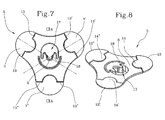
- reference numbers 7, 7' and 7" respectively indicate three projecting portions that extend away from a central portion 8, which is proximal with respect to the longitudinal axis X.
- the projecting portions 7, 7' and 7", as illustrated in Figures 5 and 6 are distributed uniformly with respect to the longitudinal axis X, that is, at about 120° with respect to each other in the case in which there are three projecting portions.
- the inclination between the lines of extension of two consecutive projecting portions is approximately 120°.
- the inclination of the lines of extension of two consecutive projecting portions is such as to ensure the presence of at least three resting points that are not aligned and not arranged in the arc of 180°.
- the stabilizing flange 5 has at least three resting points for resting it on the ground and that are distributed angularly and spaced about the longitudinal axis X so as to ensure the stability thereof.
- these resting points are identifiable at the three respective projecting portions 7, 7', 7", if present, which extend and develop prevalently along three different respective lines of extension that are inclined with respect to each other in such a manner that the arrangement of the projecting portions 7, 7', 7" ensures good stability of the stabilizing flange 5.
- the first line of extension is inclined at an angle greater or equal to 90 degrees with respect to the second line, and the latter, in turn, is inclined at an angle greater or equal to 90 degrees with respect to the third line, in such a manner as to achieve good resting efficacy and the creation of sufficient opposing action of the ground to possible inclinations of the irrigation device.
- At least two consecutive projecting portions are connected by a respective curved line 11, 11', 11", the convexity of which faces the longitudinal axis X.
- an edge 12, 12', 12" of at least one projecting portion 7, 7', 7" is at least partly curved in shape, comprising for example a circular arc.
- At least a first part of the stabilizing flange is detachable from at least a second part of the stabilizing flange.
- reference numbers 9, 9' and 9" indicate lines of weakening, each being interposed between a first part and a second part of the stabilizing flange.
- Each line of weakening is preferably configured so as to facilitate detachment of the first part from the second part.
- each projecting portion 7, 7', 7" can comprise a first part that is detachable from at least a second part of the projecting portion and/or of the central portion.
- each projecting portion 7, 7', 7" defines a first part that is detachable from a single central portion 8.
- FIG. 7 and 8 differs from that appearing in Figures 5 and 6 in terms of the procedures for fastening and moving the first part of the stabilizing flange 5 with respect to the second part of the stabilizing flange.
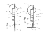
- at least a first part of the stabilizing flange is suitable for being moved with respect to at least a second part of the stabilizing flange so as to pass at least from a first position ( Figures 7-8 ), in which the first and second parts are substantially aligned so as to form the planar stabilizing surface, to a second position ( Figure 10 ), in which the planar stabilizing surface 6 is substantially defined by the second part.
- the first part of the stabilizing flange 5 is suitable for being rotated with respect to the second part of the stabilizing flange so as to pass at least from the first position to the second position, in which the first and second parts are inclined with respect to each other ( Figure 10 ).
- reference numbers 13, 13', 13" indicate respective hinges, each one being interposed between a first and a second part of the stabilizing flange, so that the first part of the stabilizing flange is suitable for being moved with respect to the second part of the stabilizing flange by means of at least one rigid motion, particularly a rigid rotation.
- first part of the stabilizing flange is suitable for being moved, preferably rotated, with respect to the second part of the stabilizing flange, by means of at least one deformation of a portion of the stabilizing flange.
- each projecting portion 7, 7', 7" can comprise a first part that is movable/rotatable with respect to at least a second part of the projecting portion and/or of the central portion.
- each projecting portion 7, 7', 7" defines a first part that is rotatable with respect to a single central portion 8.
- the first embodiment illustrates the projecting portions 7, 7' and 7" (first parts) once they have been separated from the central portion 8 of the stabilizing flange 5 (second part) for the purpose of reducing the plan area thereof to a minimum
- the projecting portions 7, 7' and 7" are turned downwards with respect to the central portion 8 (that is, on the stabilizing surface 6 side) for the same purpose.
- the fact that only some of the projecting portions 7, 7' and 7" can be detached or turned allows for a flexibility of use of the stabilizing flange 5.
- the stabilizing flange 5 comprises means for varying geometry configured to change the planar stabilizing surface 6 from an extended configuration ( Figures 5-8 ) to a contained configuration ( Figures 9-10 ) and/or vice versa.
- the means for varying geometry comprises at least the first part and at least the second part associated one with the other, for example as described previously.
- the means for varying geometry can be configured so as to define a second position ( Figure 10 ), in which the first part is suitable for being wedged into the ground.
- a second position Figure 10
- the downward rotation of the first part with respect to the second part can bring about a useful effect of fastening it to the ground derived from its being wedged into the ground.
- the means for varying geometry can be configured to operate in a reversible or irreversible manner.
- the use of a line of weakening for detaching the first part from the second part can generate means for varying geometry of a removable and irreversible type
- the use of a hinge for rotating the first part with respect to the second part can generate reversible means for varying geometry defining a rigid connection.
- limiting means configured to limit at least partially and along at least one direction, the movement, preferably the rotation, of the first part with respect to the second part.
- the means for varying geometry be capable of guaranteeing a resistance to rotation between the first part and the second part of the stabilizing flange, when the latter is in the extended configuration, a resistance that is substantially equal to the resistance that would be obtained in the absence of a means for varying geometry.
- the limiting means can be configured so as to keep the first part in its first position during insertion of the elongated body 3 into the ground 2 and/or in the case of inclination of the stabilizing flange 5 with respect to the ground 2.
- the limiting means can comprise at least one abutment portion 14, 14', 14" of the first part.
- the abutment portion 14, 14', 14" is suitable for overlapping at least partially the second part when the first part is found in the first position.
- the abutment portion 14, 14', 14" limits at least partially and at least in one direction, the rotation of the first part abutting against the second part.
- the limiting means can be configured to limit the rotation of the first part along a direction opposite the direction of the rotation that brings the first part from the first position to the second position, as illustrated for example in Figures 7 and 8 .
- At least one seat 15, 15', 15" at least partially complementary to the abutment portion14, 14', 14" is afforded in the second part.
- the seat 15, 15', 15" is configured so as to receive the abutment portion 14, 14', 14" in the first position of the first part.
- the seat 15, 15', 15" opens at least partially along a surface 16 of the stabilizing flange 5, opposite the planar stabilizing surface 6.
- the seats 15, 15' and 15" afforded in the second part of the stabilizing flange 5, preferably in the central portion 8 of the stabilizing flange 5, are also observable in Figure 10 .
- the limiting means described hereinabove in particular comprising abutment portions and possibly seats configured so as to receive the abutment portions, can also be utilized in different embodiments, for example embodiments in which the first parts, in particular the projecting portions 7, 7', 7", are rotated by means of deformation, and thus they do not have hinges.
- the projecting portion 7' which has not been sectioned, represents a first part that proves to be turned downwards, while the projecting portion 7", which has been sectioned, represents a first part that is aligned with the central portion 8 of the stabilizing flange 5.
- the coupling of the seat 15" afforded in the central portion 8 with the abutment portion 14" of the projecting portion 7" acts in such a manner that when the stabilizing flange tends to rotate so as to tilt downwards towards the projecting portion 7", the lower face of the abutment portion 14" presses on the seat 15", so that the projecting portion 7" resists rotation, as if the hinge were not present and the stabilizing flange were monolithic.
- a stabilizing flange with at least one projecting portion 7 (first part) that is detachable and at least one projecting portion (first part) that rotates rigidly, or with any combination of types of rigid or deformable constraints or a mixture thereof, which in any case, enable movement between the first part and the second part.
- the limiting means can be integrated in the same weakening lines.
- the weakening lines can be configured so as to limit rotation between the first and the second parts; for example, the lines of weakening can be suitably reinforced and resistant for that purpose.
- a line of weakening can be configured to resist the rotation of the first part and the second part with respect to each other, in such a manner that for example the line of weakening can be split only if it is subjected to a stress of a given magnitude and/or along a given direction, so that it can be broken only by the user.
- the stabilizing flange 5 is fashioned as a single piece with at least one portion of the elongated body 3.
- a coupling means for coupling the elongated body 3 and the stabilizing flange 5 fashioned as a separate piece with respect to the elongated body.
- the coupling means comprises an opening 17 afforded in the stabilizing flange 5 and that is complementary to the outer outline of the elongated body 3.
- a fork 18 afforded in the stabilizing flange 5 and extending centrally in the opening 17.
- the fork 18 is complementary to a portion of the outline of the elongated body 3.
Landscapes
- Engineering & Computer Science (AREA)
- Water Supply & Treatment (AREA)
- Life Sciences & Earth Sciences (AREA)
- Environmental Sciences (AREA)
- Nozzles (AREA)
Applications Claiming Priority (1)
| Application Number | Priority Date | Filing Date | Title |
|---|---|---|---|
| ITMO20140035 | 2014-02-18 |
Publications (1)
| Publication Number | Publication Date |
|---|---|
| EP2907375A1 true EP2907375A1 (de) | 2015-08-19 |
Family
ID=50630916
Family Applications (1)
| Application Number | Title | Priority Date | Filing Date |
|---|---|---|---|
| EP14199156.2A Withdrawn EP2907375A1 (de) | 2014-02-18 | 2014-12-19 | Eine Bewässerungseinrichtung für die kontrollierte Freisetzung einer Flüssigkeit |
Country Status (1)
| Country | Link |
|---|---|
| EP (1) | EP2907375A1 (de) |
Citations (3)
| Publication number | Priority date | Publication date | Assignee | Title |
|---|---|---|---|---|
| GB720949A (en) * | 1952-05-03 | 1954-12-29 | Harry Sigurd Valdemar Jaerund | Apparatus for irrigating pot plants or the like |
| FR2673356A1 (fr) * | 1991-03-01 | 1992-09-04 | Stroppa Mauro | Bouchon irrigateur pour bacs a plantes. |
| US5806240A (en) * | 1997-07-23 | 1998-09-15 | Racine; Pierre | System for supplying dripping water to plant growing media |
-
2014
- 2014-12-19 EP EP14199156.2A patent/EP2907375A1/de not_active Withdrawn
Patent Citations (3)
| Publication number | Priority date | Publication date | Assignee | Title |
|---|---|---|---|---|
| GB720949A (en) * | 1952-05-03 | 1954-12-29 | Harry Sigurd Valdemar Jaerund | Apparatus for irrigating pot plants or the like |
| FR2673356A1 (fr) * | 1991-03-01 | 1992-09-04 | Stroppa Mauro | Bouchon irrigateur pour bacs a plantes. |
| US5806240A (en) * | 1997-07-23 | 1998-09-15 | Racine; Pierre | System for supplying dripping water to plant growing media |
Similar Documents
| Publication | Publication Date | Title |
|---|---|---|
| ES2200840T3 (es) | Dispositivo de soporte en voladizo de un recipiente. | |
| ES2834076T3 (es) | Dispositivo de vaciado | |
| AU2020223745B2 (en) | Adhesive tape dispenser and an adhesive tape roll | |
| ES2684389T3 (es) | Utilización de un elemento de fijación rápida | |
| EP2904303B1 (de) | Ständer für eine videofotografievorrichtung | |
| EP2907375A1 (de) | Eine Bewässerungseinrichtung für die kontrollierte Freisetzung einer Flüssigkeit | |
| ES2638594T3 (es) | Recipiente y ensamblaje de tapa | |
| EP2576419B1 (de) | Ausgussvorrichtung für flaschen und ausrichtungsvorrichtung für verkorkungsanlagen | |
| JP6139499B2 (ja) | カート式液体散布装置 | |
| EP3639975B1 (de) | Stangenklemme | |
| US1017109A (en) | Disk furrow-opener. | |
| US555820A (en) | Self-measuring-faucet attachment | |
| US20190002261A1 (en) | Bottle opener and stabilizer | |
| US10631684B2 (en) | Splatter screen | |
| KR200450967Y1 (ko) | 거치대 | |
| EP1974636A1 (de) | Stützvorrichtung für Flaschenhalterbehälter | |
| US20160213169A1 (en) | Product display device | |
| EP3395220B1 (de) | Schinkenständer | |
| US1326077A (en) | Oil-barbel support | |
| JP3185595U (ja) | 歩行型管理機 | |
| WO2008079026A2 (en) | Bottle mount | |
| JP3215218U (ja) | 開缶装置 | |
| KR101607382B1 (ko) | 도마 절단장치 | |
| JP2011230858A (ja) | フレキシブルコンテナの懸吊具 | |
| GB1576606A (en) | Bracket for a shower handset |
Legal Events
| Date | Code | Title | Description |
|---|---|---|---|
| PUAI | Public reference made under article 153(3) epc to a published international application that has entered the european phase |
Free format text: ORIGINAL CODE: 0009012 |
|
| AK | Designated contracting states |
Kind code of ref document: A1 Designated state(s): AL AT BE BG CH CY CZ DE DK EE ES FI FR GB GR HR HU IE IS IT LI LT LU LV MC MK MT NL NO PL PT RO RS SE SI SK SM TR |
|
| AX | Request for extension of the european patent |
Extension state: BA ME |
|
| 17P | Request for examination filed |
Effective date: 20160202 |
|
| RBV | Designated contracting states (corrected) |
Designated state(s): AL AT BE BG CH CY CZ DE DK EE ES FI FR GB GR HR HU IE IS IT LI LT LU LV MC MK MT NL NO PL PT RO RS SE SI SK SM TR |
|
| RIN1 | Information on inventor provided before grant (corrected) |
Inventor name: RIGHI, CESARE MATTIA |
|
| GRAP | Despatch of communication of intention to grant a patent |
Free format text: ORIGINAL CODE: EPIDOSNIGR1 |
|
| INTG | Intention to grant announced |
Effective date: 20180518 |
|
| STAA | Information on the status of an ep patent application or granted ep patent |
Free format text: STATUS: THE APPLICATION IS DEEMED TO BE WITHDRAWN |
|
| 18D | Application deemed to be withdrawn |
Effective date: 20180929 |