EP2906339B1 - Procédé pour surveiller et réguler la réaction chimique exothermique entre ammoniac et l' hypochlorite de sodium - Google Patents
Procédé pour surveiller et réguler la réaction chimique exothermique entre ammoniac et l' hypochlorite de sodium Download PDFInfo
- Publication number
- EP2906339B1 EP2906339B1 EP13774012.2A EP13774012A EP2906339B1 EP 2906339 B1 EP2906339 B1 EP 2906339B1 EP 13774012 A EP13774012 A EP 13774012A EP 2906339 B1 EP2906339 B1 EP 2906339B1
- Authority
- EP
- European Patent Office
- Prior art keywords
- reactant
- temperature
- temperature difference
- reaction
- reaction product
- Prior art date
- Legal status (The legal status is an assumption and is not a legal conclusion. Google has not performed a legal analysis and makes no representation as to the accuracy of the status listed.)
- Active
Links
Images


Classifications
-
- C—CHEMISTRY; METALLURGY
- C01—INORGANIC CHEMISTRY
- C01B—NON-METALLIC ELEMENTS; COMPOUNDS THEREOF; METALLOIDS OR COMPOUNDS THEREOF NOT COVERED BY SUBCLASS C01C
- C01B21/00—Nitrogen; Compounds thereof
- C01B21/082—Compounds containing nitrogen and non-metals and optionally metals
- C01B21/087—Compounds containing nitrogen and non-metals and optionally metals containing one or more hydrogen atoms
- C01B21/088—Compounds containing nitrogen and non-metals and optionally metals containing one or more hydrogen atoms containing also one or more halogen atoms
- C01B21/09—Halogeno-amines, e.g. chloramine
- C01B21/091—Chloramine, i.e. NH2Cl or dichloramine, i.e. NHCl2
-
- B—PERFORMING OPERATIONS; TRANSPORTING
- B01—PHYSICAL OR CHEMICAL PROCESSES OR APPARATUS IN GENERAL
- B01J—CHEMICAL OR PHYSICAL PROCESSES, e.g. CATALYSIS OR COLLOID CHEMISTRY; THEIR RELEVANT APPARATUS
- B01J14/00—Chemical processes in general for reacting liquids with liquids; Apparatus specially adapted therefor
-
- B—PERFORMING OPERATIONS; TRANSPORTING
- B01—PHYSICAL OR CHEMICAL PROCESSES OR APPARATUS IN GENERAL
- B01J—CHEMICAL OR PHYSICAL PROCESSES, e.g. CATALYSIS OR COLLOID CHEMISTRY; THEIR RELEVANT APPARATUS
- B01J19/00—Chemical, physical or physico-chemical processes in general; Their relevant apparatus
- B01J19/0006—Controlling or regulating processes
- B01J19/0013—Controlling the temperature of the process
-
- B—PERFORMING OPERATIONS; TRANSPORTING
- B01—PHYSICAL OR CHEMICAL PROCESSES OR APPARATUS IN GENERAL
- B01J—CHEMICAL OR PHYSICAL PROCESSES, e.g. CATALYSIS OR COLLOID CHEMISTRY; THEIR RELEVANT APPARATUS
- B01J2219/00—Chemical, physical or physico-chemical processes in general; Their relevant apparatus
- B01J2219/00049—Controlling or regulating processes
- B01J2219/00051—Controlling the temperature
- B01J2219/00054—Controlling or regulating the heat exchange system
- B01J2219/00056—Controlling or regulating the heat exchange system involving measured parameters
- B01J2219/00058—Temperature measurement
- B01J2219/00063—Temperature measurement of the reactants
-
- B—PERFORMING OPERATIONS; TRANSPORTING
- B01—PHYSICAL OR CHEMICAL PROCESSES OR APPARATUS IN GENERAL
- B01J—CHEMICAL OR PHYSICAL PROCESSES, e.g. CATALYSIS OR COLLOID CHEMISTRY; THEIR RELEVANT APPARATUS
- B01J2219/00—Chemical, physical or physico-chemical processes in general; Their relevant apparatus
- B01J2219/00049—Controlling or regulating processes
- B01J2219/00164—Controlling or regulating processes controlling the flow
-
- B—PERFORMING OPERATIONS; TRANSPORTING
- B01—PHYSICAL OR CHEMICAL PROCESSES OR APPARATUS IN GENERAL
- B01J—CHEMICAL OR PHYSICAL PROCESSES, e.g. CATALYSIS OR COLLOID CHEMISTRY; THEIR RELEVANT APPARATUS
- B01J2219/00—Chemical, physical or physico-chemical processes in general; Their relevant apparatus
- B01J2219/00049—Controlling or regulating processes
- B01J2219/00191—Control algorithm
- B01J2219/00193—Sensing a parameter
- B01J2219/00195—Sensing a parameter of the reaction system
- B01J2219/00198—Sensing a parameter of the reaction system at the reactor inlet
-
- B—PERFORMING OPERATIONS; TRANSPORTING
- B01—PHYSICAL OR CHEMICAL PROCESSES OR APPARATUS IN GENERAL
- B01J—CHEMICAL OR PHYSICAL PROCESSES, e.g. CATALYSIS OR COLLOID CHEMISTRY; THEIR RELEVANT APPARATUS
- B01J2219/00—Chemical, physical or physico-chemical processes in general; Their relevant apparatus
- B01J2219/00049—Controlling or regulating processes
- B01J2219/00191—Control algorithm
- B01J2219/00193—Sensing a parameter
- B01J2219/00195—Sensing a parameter of the reaction system
- B01J2219/00202—Sensing a parameter of the reaction system at the reactor outlet
-
- B—PERFORMING OPERATIONS; TRANSPORTING
- B01—PHYSICAL OR CHEMICAL PROCESSES OR APPARATUS IN GENERAL
- B01J—CHEMICAL OR PHYSICAL PROCESSES, e.g. CATALYSIS OR COLLOID CHEMISTRY; THEIR RELEVANT APPARATUS
- B01J2219/00—Chemical, physical or physico-chemical processes in general; Their relevant apparatus
- B01J2219/00049—Controlling or regulating processes
- B01J2219/00191—Control algorithm
- B01J2219/00211—Control algorithm comparing a sensed parameter with a pre-set value
- B01J2219/00213—Fixed parameter value
-
- B—PERFORMING OPERATIONS; TRANSPORTING
- B01—PHYSICAL OR CHEMICAL PROCESSES OR APPARATUS IN GENERAL
- B01J—CHEMICAL OR PHYSICAL PROCESSES, e.g. CATALYSIS OR COLLOID CHEMISTRY; THEIR RELEVANT APPARATUS
- B01J2219/00—Chemical, physical or physico-chemical processes in general; Their relevant apparatus
- B01J2219/00049—Controlling or regulating processes
- B01J2219/00191—Control algorithm
- B01J2219/00211—Control algorithm comparing a sensed parameter with a pre-set value
- B01J2219/0022—Control algorithm comparing a sensed parameter with a pre-set value calculating difference
-
- B—PERFORMING OPERATIONS; TRANSPORTING
- B01—PHYSICAL OR CHEMICAL PROCESSES OR APPARATUS IN GENERAL
- B01J—CHEMICAL OR PHYSICAL PROCESSES, e.g. CATALYSIS OR COLLOID CHEMISTRY; THEIR RELEVANT APPARATUS
- B01J2219/00—Chemical, physical or physico-chemical processes in general; Their relevant apparatus
- B01J2219/00049—Controlling or regulating processes
- B01J2219/00191—Control algorithm
- B01J2219/00222—Control algorithm taking actions
- B01J2219/00225—Control algorithm taking actions stopping the system or generating an alarm
-
- B—PERFORMING OPERATIONS; TRANSPORTING
- B01—PHYSICAL OR CHEMICAL PROCESSES OR APPARATUS IN GENERAL
- B01J—CHEMICAL OR PHYSICAL PROCESSES, e.g. CATALYSIS OR COLLOID CHEMISTRY; THEIR RELEVANT APPARATUS
- B01J2219/00—Chemical, physical or physico-chemical processes in general; Their relevant apparatus
- B01J2219/00049—Controlling or regulating processes
- B01J2219/00191—Control algorithm
- B01J2219/00222—Control algorithm taking actions
- B01J2219/00227—Control algorithm taking actions modifying the operating conditions
- B01J2219/00229—Control algorithm taking actions modifying the operating conditions of the reaction system
- B01J2219/00231—Control algorithm taking actions modifying the operating conditions of the reaction system at the reactor inlet
Definitions
- the present invention relates generally to the field of monitoring and controlling an exothermic chemical reaction wherein ammonia is reacted with sodium hypochlorite and the reaction product comprises monochloramine.
- the minimum amount of monochloramine that can be produced by commercial generation equipment available today is over one hundred pounds (45 kg) of NH 2 Cl per day. While this quantity is appropriate for large-scale industrial applications (paper mills, electric utility generating plants, and the like), there are many smaller-scale applications (reverse-osmosis systems, cooling towers for office buildings, and the like) that require only one-tenth (or less) of the minimum amount that existing commercial units produce. Reducing the size of the equipment is not straightforward, because the safety features of the existing equipment rely upon the use of pumps and flow meters that can reliably deliver precise flow rates. Pumps and flow meters are available that will work with a similar level of precision at these low mL/minute flow rates; however, these devices would be expensive and would tend to be too delicate for typical industrial applications.
- EP 2 495 260 A1 discloses a reactor and a method of controlling it during a vapor-phase polymerization process, wherein the temperature is measured by sensors along a reactor, but does not relate to bleach:ammonia reactions.
- the deficiencies mentioned above are overcome by a method that uses temperature differences to monitor and control an exothermic chemical reaction. It is an object of the present invention to provide a robust, low-maintenance, low-cost method for monitoring and controlling the combination of ammonia and sodium hypochlorite that will undergo an exothermic reaction.
- the present method is useful in preventing damage and/or injury that could result from violent, uncontrolled reactions and are also useful in optimizing a combination of reactants used to generate a desired product.
- an electronic device is used to monitor the combination of bleach with an ammonia solution to ensure that the ratio of sodium hypochlorite to ammonia is correct.
- An increase in the temperature of the reaction mixture beyond that which is expected for the desired reaction can be detected and used to generate a signal that can be used to adjust a flow rate or shut off one or more chemical feed pumps until the error is corrected.
- the apparatus can be configured so that the adjustment or shut down occurs automatically.
- a desired reaction of bleach with ammonia to form monochloramine results in a temperature change, in this case, a temperature rise, of approximately one centigrade degree when the reactants are mixed at a proper ratio. If a greater temperature increase or lesser temperature increase is detected, adjustments to the flow rate of one or more of the reactants can be used to provide a more proper ratio of reactants, a more desired reaction, and a better yield of reaction product.
- the method can be used to provide safe and reliable systems for generating monochloramine solutions, for example, relatively small volumes of monochloramine solutions (5-10 lbs or 2.25-4.5 kg NH 2 Cl/day) for water treatment or other applications.
- the present invention provides a method for mixing at least two reactants or components to form a reaction product.
- the method and apparatus can be useful in controlling reactions that are inherently dangerous, for example, wherein the mixing of the components has the potential to produce hazardous compounds or components.
- precautions are taken to ensure that the molar ratio of each reactant is precisely metered, as well as incoming makeup water if used in the reaction.
- the method comprises mixing an ammonia-containing chemical (i.e., ammonia) and a hypochlorite-containing chemical (i.e., comprising sodium hypochlorite), the nature of which is inherently dangerous.
- the mixing of an ammonia-containing chemical and a hypochlorite-containing chemical must be controlled carefully to avoid the production of hazardous compounds such as dichloramine, trichloramine, and chlorine gas.
- a differential temperature method of controlling the exothermic chemical reaction includes measuring a temperature of the first reactant flowing at a first flow rate, contacting the first reactant with the second reactant, and then measuring the temperature of a reaction product formed by a reaction between the first and second reactants.
- the temperature difference between the measured temperature of the first reactant and the measured temperature of the reaction product can be used to monitor the reaction, and adjustments are made based on the temperature difference.
- the flow rate of the first reactant is adjusted based on the temperature difference.
- the second reactant can be made to flow at a second flow rate, and the flow rate of the first reactant and the second reactant are adjusted based on the temperature difference.
- the first temperature reading can occur right before (e.g., 1 second or several seconds before) the second reactant is brought into contact (e.g., combined) with the first reactant.
- the first temperature reading can optionally be right at the initial time that the reactants are brought together or some other time if desired.
- the second reading, used to obtain the temperature differential can be a time where maximum temperature increase occurs from the reaction. The present invention uses this temperature difference from the reaction to determine and/control the reaction to ensure that the reaction and the product from the reaction is the desired reaction product and/or to ensure that reaction is proceeding in an efficient or correct manner.
- a time can be selected for the second temperature reading to take place, depending on the reaction.
- the second temperature reading can occur anywhere from about 5 seconds to about 30 minutes or more, and can depend on the speed of the reaction and reactants involved.
- this temperature difference can be monitored on a continuous or nearly continuous basis (e.g., meaning that delta T readings are being made/determined continuously or nearly continuously) to ensure that the reaction product being semi-continuously or continuously formed is the desired product based on determining/monitoring the temperature difference as described herein.
- the contacting of the first and second reactants occurs under conditions that cause the first and second reactants to react with one another and form a reaction product.
- One or more additional reactants or reagents can also be a part of the reaction; and the flow rate of at least one of the additional reactants or reagents can also, or instead, be adjusted based on the temperature difference.
- the flow rate of a reactant or reagent can be controlled by controlling the speed of one or more metering pumps.
- the method further includes combining the reaction product with an aqueous source such as industrial water, process water, cooling tower water, or potable water.
- the present invention comprises the reaction between ammonia, as the first reactant, and sodium hypochlorite or bleach, as the second reactant; and the reaction product obtained is monochloramine.
- the concentration of the reactants one or both of them can be diluted, for example, with dilution water. Dilution can occur just prior to the reaction, or one or more of the reactants can be prediluted.
- a supply of diluent can be provided and configured to flow through the apparatus even in the event that one or both of the supplies of reactants is shut down.
- the first reactant can be prepared by diluting an ammonia solution with dilution water or makeup water; and in such a case the temperature of the first reactant can be is measured at the point where the ammonia solution is contacted with the makeup water.
- the apparatus used in the present invention can include a reactor, a reactor system, a generator, a small-volume generator, a vessel, or an in-line mixer.
- the apparatus can include a first conduit through which the first reactant flows, and a second conduit through which the second reactant flows.
- the first and second conduits can each be in fluid communication with a reactor or an in-line mixer, in which contact between the first and second reactants can occur.
- the first reactant can be a diluted ammonia solution, and the second reactant comprises sodium hypochlorite.
- the apparatus can be configured to produce any amount of monochloramine including, but not limited to, 20 pounds (9 kg) or more of monochloramine per day, or less than this amount.
- the temperature difference monitored by the method and apparatus can be compared to acceptable and unacceptable values or ranges to determine whether adjustments should be made.
- the target temperature difference that would indicate a proper ratio of reactants can be dependent on the reaction being carried out but can be about 10.0 °C or less, for example, a temperature difference of about 2.0 °C or less.
- the apparatus can be configured such that, if it is determined that the temperature difference is outside an acceptable range, an alarm can be activated indicating that the temperature difference is outside the acceptable range.
- the apparatus can be configured such that, if it is determined that the temperature difference is above a maximum value, a first alarm can be activated indicating that the temperature difference is above the maximum value.
- the apparatus can be configured such that, if it is determined that the temperature difference is below a minimum value, a second alarm can be activated, that differs from the first alarm, indicating that the temperature difference is below the minimum value.
- the apparatus can be configured to measure the temperatures of the first and second reactants, determine first and second temperature differences between the measured temperatures of the first and second reactants, respectively, and the measured temperature of the reaction product.
- the flow rate of the first reactant and/or the second reactant can then be adjusted based on either or both of the first and second temperature differences.
- the apparatus can include a reactor, for example, a conduit, a vessel, an in-line mixer, or any combination thereof.
- a first conduit can be in fluid communication with the reactor and a first pump can be configured to move a first reactant through the first conduit and into the reactor.
- a first temperature sensor can be configured to measure the temperature of a first reactant flowing through the first conduit.
- a second conduit can also be in fluid communication with the reactor.
- a second pump can be configured to move a second reactant through the second conduit and into the reactor.
- a second temperature sensor can be configured to measure the temperature of a reaction product in, exiting, or after having exited, the reactor.
- a control unit can be configured to determine a temperature difference between a temperature measured by the first temperature sensor and a temperature measured by the second temperature sensor and can be configured to adjust the first pump, the second pump, or both, based on the temperature difference.
- the apparatus can include, independently, as each of the first temperature sensor and the second temperature sensor, thermocouple sensors, platinum resistance thermometers, thermistors, or a combination thereof.
- the apparatus can be in fluid communication with a source of the first reactant, i.e., an ammonia solution.
- a first conduit can provide a fluid communication between the source and the reactor.
- a source of the second reactant comprising sodium hypochlorite, can be provided in fluid communication with a second conduit which, in turn, is in fluid communication with the reactor.
- the apparatus can further include a third pump configured to pump diluent, such as dilution water, through one or both of the first conduit and the second conduit.
- the control unit can be configured or programmed to maintain operation of the third pump and stop operation of the first pump, the second pump, or both, in the event of an alarm condition.
- the apparatus can include one or more alarms or alarm systems.
- the apparatus can include an alarm configured to be activated by the control unit in the event that the control unit determines an unacceptable temperature difference.
- Each of the first pump, the second pump, and optionally a third pump can be a peristaltic pump.
- the apparatus can include a graphical user interface configured for a user to input one or more processing parameters, for instance, one or more flow rates, pump speeds, metering quantities, temperatures, temperature differentials, or temperature thresholds.
- the graphical user interface can be configured for a user to input (1) a first flow rate of a first reactant, (2) a second flow rate of a second reactant, and (3) acceptable ranges of temperature differentials.
- the temperature differentials can be differences between a temperature measured by the first temperature sensor and a temperature measured by the second temperature sensor.
- the control unit can be configured to control the first pump based on the inputted first flow rate and to control the second pump based on the inputted second flow rate.
- the control unit can be configured to control a third pump for diluent, one or more valves, one or more regulators, one or more calibration columns, one or more calibration systems, one or more shut-off valves, one or more thresholds, or any combinations thereof.
- the method of the present invention can provide for the safe operation of equipment for a chemical reaction.
- the operation of equipment for the on-site generation of monochloramine is enabled and can be achieved by precisely controlling the flow rates of dilution water, bleach, and ammonia solution so the reactants are contacted together at a proper ratio.
- the contact can be made merging flows of the reactants together in a conduit, by an online static mixer, within a reactor, or in a similar vessel or container. Once pump speeds, flow controls, or both, have been set, the apparatus can regulate the flows of dilution water, bleach, and ammonia to provide a desired mixture.
- the controls can be set properly when a 1:1 molar ratio of sodium hypochlorite to ammonia is obtained, and the feed system can precisely regulate the flows to maintain the 1:1 molar ratio. If an event occurs that alters these reaction conditions, such as an interruption in the flow of dilution water, the apparatus can be configured to automatically shut down so as to eliminate the possibility of combining the bleach and ammonia solution in a ratio that might lead to a violent, uncontrolled reaction.
- a rapid temperature increase of the reaction product, relative to the first or second reactant can occur, for example, an increase of more than one degree centigrade or of several degrees centigrade.
- the apparatus can be configured such that, when an unacceptable temperature increase is detected, the apparatus takes steps to control the reaction, activate an alarm, or both.
- the chemical feed pumps can be adjusted or shut down.
- the flow of bleach, ammonia, dilution water, or any combination thereof can independently be increased, decreased, or shut down.
- an alarm circuit can be activated. A combination of these steps and alerts can be implemented, For example, the chemical feed pumps can be shut down and/or an alarm can be activated.
- the apparatus can be set so that an unacceptable temperature increase can fluctuate with conditions, be dependent on reactor conditions, and/or depend on the starting temperature of one or more reactants, or depend on any combination thereof.
- An unacceptable temperature increase can be a temperature increase of 1.1 degrees centigrade or more, a temperature increase of 1.2 degrees centigrade or more, a temperature increase of 1.3 degrees centigrade or more, a temperature increase of 1.4 degrees centigrade or more, a temperature increase of 1.5 degrees centigrade or more, a temperature increase of 1.75 degrees centigrade or more, a temperature increase of 2.0 degrees centigrade or more, a temperature increase of 2.5 degrees centigrade or more, a temperature increase of 3.0 degrees centigrade or more, or even a higher temperature increase.
- the apparatus can be configured such that, when a temperature increase of less than one degree is detected, the apparatus takes steps to control the reaction, activate an alarm, or both.
- the steps can include adjusting or shutting down the chemical feed pumps.
- the flow of bleach, ammonia and/or dilution water, or any combination thereof, can independently be increased, decreased, or shut down.
- an alarm circuit can be activated.
- a combination of these steps and alerts can be implemented, for example, the chemical feed pumps can be shut down and an alarm can be activated. In the event of too little of a temperature increase, an alarm circuit can be activated to alert the operator to the error that is different from the alarm circuit activated for too high or rapid a temperature increase.
- a temperature increase of significantly less than one degree centigrade can be designated as unacceptable.
- a temperature increase of significantly less than one degree centigrade can be a temperature increase of only 0.9 degree centigrade or less, a temperature increase of only 0.8 degree centigrade or less, a temperature increase of only 0.7 degree centigrade or less, a temperature increase of only 0.6 degree centigrade or less, a temperature increase of only 0.5 degree centigrade or less, a temperature increase of only 0.25 degree centigrade or less, no temperature increase, or a temperature decrease.
- the differential temperature measurement method can offer several advantages over alternative techniques.
- the temperature differential provides an instantaneous indication of an incorrect ratio of reactants, allowing corrective action to be taken before a serious hazard can develop.
- the measurement procedure does not require any chemical additions, such as titrants or color-development reagents that are required by many existing methods. As a result of these advantages, routine maintenance is significantly reduced. Without the moving parts of on-line titration or colorimetric equipment, the apparatus of the present invention has fewer failure modes and is consequently more reliable than existing systems.
- the method can monitor the increase in temperature and use the temperature increase as a triggering parameter, rather than using the absolute temperature of the reaction product.
- the present invention involves acquiring a differential temperature measurement.
- a first temperature can be measured at the point where an ammonia solution is combined with dilution water.
- a second temperature measurement can be made where the bleach subsequently comes into contact with the diluted ammonia solution, or downstream thereof.
- the contact between these reactants, and the second measurement can occur in, or downstream of, a static in-line mixer, or, for example, in a reactor.
- the difference between the first temperature and the second temperature can be determined electronically and can be used to monitor and control the reactant/chemical feed pumps.
- the temperature of the second reactant for example, the bleach in the exemplary reaction described above, can be monitored and taken into consideration when determining whether an unacceptable temperature increase or decrease has occurred. If one reactant is warmer than another reactant, the reaction product between the two reactants can be at a temperature that is between the two. The reaction product temperature can thus be cooler than the temperature of the warmer reactant. This can be the result despite the fact that an exothermic reaction has taken place. Thus, in some cases, the temperatures of two or more reactants are considered and monitored when determining acceptable limits of temperature increases or decreases to form the reaction product.
- the reaction product (monochloramine) is at a temperature that is lower than the temperature of one of the reactants (the ammonia solution).
- the reaction product temperature is less than the temperature of one of the reactants despite an exothermic reaction having taken place.
- thermocouple sensors can be used to measure the temperatures of the solutions. It is to be understood that other electronic temperature sensors can be used as well. Platinum resistance thermometers (RTDs) or thermistors can be used, for example, if additional resolution or accuracy is desired or needed.
- the method can be used to provide safe and reliable systems for generating relatively small volumes of monochloramine solutions (2.25-4.5 kg NH 2 Cl/day) for water treatment or other applications.
- the method can be used to produce products for industrial water treatment, cooling water treatment, influent/effluent treatment, in reverse-osmosis systems, in the treatment of process waters, in the treatment of pulp and paper materials, in the disinfection of potable water, in disinfection for food-processing applications, and generally in any industrial process that involves an endothermic or exothermic chemical reaction.
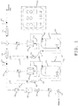
- FIG. 1 is a schematic flow diagram of an example of a small-volume monochloramine generator.
- a small-volume generator is exemplified below, large-volume or larger-volume generators can implement the methods of the present invention.
- the same generator, or a similar generator and set-up, can be used to monitor and control other reactions, in accordance with the present invention.
- dilution water or makeup water from a water-in source can be made to flow through a pressure regulator 18, a check valve 20, a needle valve 26, and an in-line flow meter 28 en route to a flow switch 24.
- These components can be used to precisely control the flow of dilution water into a tee connection 60.
- a source of an ammonia solution can be stored in a chemical storage tank 44 that is positioned within a secondary containment chemical tank 42.
- Ammonia solution from chemical storage tank 44 can exit the tank through a chemical tank valve 46 and pass through a tee connection 30 en route to a metering pump 38.
- Metering pump 38 can be contained within a secondary pump container 50.
- a pump exhaust line 48 can be provided in fluid communication with metering pump 38 and chemical storage tank 44 to complete a priming loop between chemical storage tank 44 and metering pump 38.
- Tee connection 30 can also be in fluid communication with a calibration column 36 through a ball valve 40. Calibration column 36 can be used to calibrate metering pump 38.
- Ammonia solution can be pumped by metering pump 38 through a check valve 22 and into tee connection 60 where the ammonia solution can be contacted with and diluted by the makeup water.
- the temperature of the diluted ammonia solution downstream of tee connection 60 can be measured by a dual output thermocouple 62 (perfluoroalkoxy-coated) positioned immediately downstream of tee connection 60. Thermocouple 62 can be used to attain the first temperature described herein.
- Downstream of thermocouple 62 and tee connection 60 is an in-line static mixer 64 that is configured to thoroughly mix the ammonia solution with the dilution water.
- a supply of bleach stored in a chemical storage tank 45 can be directed to merge with the diluted ammonia solution at a tee connection 61.
- Chemical storage tank 45 is contained within a secondary containment chemical tank 43. Bleach from inside chemical storage tank 45 can flow through a chemical tank valve 47 to a tee connection 31 and from tee connection 31 to a metering pump 39.
- Metering pump 39 is contained within a secondary pump container 51.
- a pump exhaust line 49 is provided in fluid communication with metering pump 39 and chemical storage tank 45 to complete a priming loop for metering pump 39.
- a calibration column 37 is provided in fluid communication with tee connection 31 through a ball valve 41, and can be used to calibrate metering pump 39 or other aspects of the generator. From metering pump 39, bleach can be directed toward and through check valve 23 to tee connection 61 where it contacts the diluted ammonia solution.
- the diluted ammonia solution and the bleach can be made to contact each other at tee connection 61 and flow downstream together toward and through an in-line static mixer 65.
- In-line static mixer 65 can ensure that the diluted ammonia solution and the bleach are thoroughly mixed together.
- the thorough mixing by in-line static mixer 65 facilitates a homogeneous mixture of the reactants, maximizes the yield of reaction product, and ensures a more accurate downstream temperature measurement.
- the generator shown in Fig. 1 is also provided with a control unit or controller 52 that is operably connected to many components of the generator.
- Control unit 52 is configured to control the speed of metering pumps 38 and 39, and the various valves and regulators used to control the flow of dilution water.
- Controller 52 can be in electrical communication with thermocouples 62 and 63 and can be configured to receive temperature signals from thermocouples 62 and 63.
- Controller 52 can include a processor that can determine the difference between a temperature detected by thermocouple 63 and a temperature detected by thermocouple 62, and can use the temperature difference to maintain, adjust, or shut down the speed of metering pump 38, metering pump 39, or both.
- thermocouple 62 and thermocouple 63 can be used by controller 52 to determine a temperature differential and control one or more of chemical tank valves 46 and 47, check valves 20, 22, and 23, needle valve 26, in-line flow meter 28, flow switch 24, ball valves 40 and 41, and in-line static mixers 64 and 65. Operable connections can be made between controller 52 and any or all of these components.
- In-line flow meter 28 can be in electrical communication with controller 52 and a flow signal generated by in-line flow meter 28 can be used by controller 52 to control one or more components of the generator.
- the small-volume generator depicted in Fig. 1 has great flexibility and can be used for carrying out many chemical reactions besides the monochloramine reaction exemplified in detail herein.
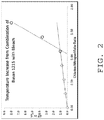
- FIG. 2 is a graph demonstrating that when using a proper ratio of bleach to ammonia and thus a proper molar ratio of chlorine to nitrogen a temperature rise of approximately one centigrade degree results.
- FIG. 2 also shows that at molar ratios greater than 1:1, much more rapid temperature increases result.
- Precise control over the molar ratio of the reactants can be important in controlling a desired reaction. Precise control is provided by using the method and apparatus of the present invention.
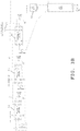
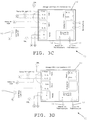
- FIGS. 3A-3G are schematic diagrams of a control scheme for controlling a small-volume generator useful in the production of monochloramine, according to an example of the present invention.
- a three-part control scheme can be built into the controls of the apparatus. Such a control scheme can prevent a potentially dangerous situation from occurring.
- the three-part control scheme can include: control 1 - redundant dual output temperature monitoring; control 2 - makeup water flow switch; and control 3 - low temperature indicators.
- An example of such a control scheme is shown in the electrical circuits depicted in FIGS. 3A-3G .
- the circuitry shown can be used in controlling the apparatus shown in FIG. 1 .
- FIGS. 3A-3G are schematic diagrams of a control scheme that is useful, for example, in a small-volume generator for the production of monochloramine from bleach, an ammonia solution, and dilution (makeup) water.
- the first control feature of the control scheme shown in FIGS. 3A-3G involves redundant dual output temperature monitoring.
- FIG. 3A shows a portion of the control scheme including a circuit having a control block line 66 and a terminal block line 68 exemplary of the respective lines that are wired to the control block lines (CBL) and terminal block lines (TBL) shown in FIGS. 3B-3G .
- the control scheme includes two sets (70 shown in FIG. 3C and 72 shown in FIG.
- thermocouples 74, 76, 78, 80 are wired in series to an Omega process controller 82, 84 (also shown in FIGS. 3C and 3D ) from Omega Engineering, Inc., of Stamford, Connecticut.
- Omega process controller 82, 84 has independent control over the chemical feed pumps so if either controller 82, 84 determines an unsafe condition the chemical feed pumps can be shut down.
- controllers 82, 84 are wired to latching relays 82,84 from which power out line to latching relay 86 is wired.
- Latching relay 86 is controlled by the flow switch 90, which will sense a low flow condition for the dilution water.
- the power out line 88 for powering the chemical feed pumps (shown in FIG. 3B ) is wired through latching relay 82 (controlled by the Omega process controller 82 shown in FIG. 3C ), through latching relay 84 (controlled by Omega process controller 84 shown in FIG. 3D ), and through latching relay 86 (controlled by the dilution water flow switch 90).
- the control scheme can indicate the operating state of the chemical pumps. Whether the chemical pumps are on or off can be indicated by a chemical pumps ON light 92 and a chemical pumps OFF light 94, which are wired to the chemical pumps and to a non-latching relay 96 as shown in FIG. 3E .
- FIGS. 3F and 3G The electrical outlets and circuits therefore are shown in FIGS. 3F and 3G , as are the lines and switches wired to the outlets.
- the pump outlet 97 for powering the ammonia solution pump depicted as 1215 Pump Outlet
- the pump outlet 99 for powering the bleach pump depicted as Bleach Outlet
- the pump outlet 105 for powering the water pump is not wired to a switch.
- FIG. 3G shows that the pump outlet 105, which is also for powering the bleach pump, is wired to a switch 106 that inturn is wired to terminal block line 108.
- thermocouples monitor the temperature increase or differential between two chemical feed points, and for the monochloramine reaction scheme shown, the feed points are where an ammonia solution is diluted with dilution water and where the bleach contacts the diluted ammonia solution. If the temperature increase extends beyond a user programmed setpoint, the controllers 82, 84 will turn off both of the chemical feed pumps while keeping the makeup water pump on. This enables the makeup water to continue to flow and sweep away any hazardous chemical present in the reactor or reaction conduits, and in-line static mixers. An operator can manually restart the chemical pumps once it is safe for proper operation. Using this setup, if one controller 82, 84 or one thermocouple 74, 76, 78, 80 were to fail, the other controller 82, 84 would still provide proper safety should the temperature increase be indicative of unsafe process conditions.
- the second control feature of the control scheme shown in FIGS. 3A-3G involves the use of a makeup water flow switch 90, as shown in FIG. 3B .
- Flow switch 90 can be mounted in the makeup water inlet and wired to latching relay 86. If the makeup water flow were to fall below a minimum user programmed set point, or stop flowing completely, flow switch 90 would activate latching relay 86 thereby shutting off power to the chemical feed pumps. An operator can restart the apparatus manually once it is safe for proper operation.
- the third control feature of the control scheme shown in FIGS. 3A-3G involves the use of low temperature indicator lights 92, 94, shown in the circuits of FIGS. 3C and 3D .
- the temperature increase between the two feed points is expected to be within certain parameters. If the differential temperature falls below these parameters, either or both low temperature indicator lights 92, 94 will turn on, thereby alerting the operator that the unit is not performing optimally.
- the apparatus can be configured such that low temperature indicator lights 92, 94 turn on when one of the chemical feed pumps has malfunctioned, when the makeup water flow rate is too great, or under either condition.
- control unit can include one or more low temperature indicator lights configured to turn on when any chemical pump is not working properly or when a makeup water flow rate exceeds a threshold level.
- the threshold level can be set by an operator through a graphical user interface that may be a part of the control unit.
- the apparatus can further be configured such that when one or both of low temperature indicator lights 92, 94 comes on power is not disabled to the chemical feed pumps if a low temperature differential is not inherently dangerous in view of the reaction being carried out. If one of the chemical pumps were to fail or the makeup water flow were to become too great, it may be better to feed one of the reactants as a biocide or as a more diluted product mixture. The operator could still be alerted that the unit is not properly functioning but the result may be more desirable than disabling the pumps completely.
Landscapes
- Chemical & Material Sciences (AREA)
- Organic Chemistry (AREA)
- Chemical Kinetics & Catalysis (AREA)
- Inorganic Chemistry (AREA)
- Physical Or Chemical Processes And Apparatus (AREA)
- Treatment Of Water By Oxidation Or Reduction (AREA)
- Agricultural Chemicals And Associated Chemicals (AREA)
- Investigating Or Analyzing Non-Biological Materials By The Use Of Chemical Means (AREA)
- Organic Low-Molecular-Weight Compounds And Preparation Thereof (AREA)
Claims (9)
- Procédé de commande d'une réaction chimique exothermique comprenant :la mesure d'une température d'un premier réactif s'écoulant à un premier débit ;le contact ultérieur du premier réactif avec un second réactif s'écoulant à un second débit, le contact apparaissant dans des conditions qui amènent les premier et second réactifs à réagir l'un avec l'autre dans une réaction chimique exothermique et former un produit de réaction, dans lequel le premier réactif comprend de l'ammoniaque, le second réactif comprend de l'hypochlorite de sodium, et le produit de réaction comprend de la monochloramine ;la mesure de la température du produit de réaction dans, ou en aval de, un mélangeur en ligne statique ou dans un réacteur ;la détermination de la différence de température entre la température mesurée du premier réactif et la température mesurée du produit de réaction ;l'ajustement du débit d'au moins un parmi le premier réactif et le second actif si la différence de température atteint une différence de température prédéterminée ; etla combinaison du produit de réaction avec une source d'eau industrielle, eau de traitement, eau de tour de refroidissement, eau potable, ou pulpe et matériaux de papier.
- Procédé selon la revendication 1, comprenant en outre la préparation du premier réactif par dilution d'une solution d'ammoniaque avec de l'eau de dilution, dans lequel la température du premier réactif est mesurée au moment où la solution d'ammoniaque est en contact avec l'eau de dilution.
- Procédé selon la revendication 1, dans lequel le premier réactif s'écoule au travers d'un premier conduit, le second réactif s'écoule au travers d'un second conduit, les premier et second conduits sont chacun en communication fluidique avec un réacteur, et le contact se produit dans le réacteur.
- Procédé selon la revendication 3, dans lequel le premier réactif est une solution d'ammoniaque diluée, le second réactif est de l'hypochlorite de sodium, et le réacteur est configuré pour ne pas produire plus de dix livres (4,5 kg) de monochloramine par jour.
- Procédé selon la revendication 1, dans lequel la différence de température est de 10,0 °C ou moins.
- Procédé selon la revendication 1, comprenant en outre la détermination que la différence de température est en dehors d'une plage présentant une valeur maximum et une valeur minimum pour la différence de température et l'activation d'une alarme indiquant que la différence de température est en dehors de la plage.
- Procédé selon la revendication 1, comprenant en outre la détermination que la différence de température est supérieure à une valeur maximum et l'activation d'une première alarme indiquant que la différence de température est supérieure à la valeur maximum.
- Procédé selon la revendication 7, comprenant en outre la détermination que la différence de température est inférieure à une valeur minimum et l'activation d'une seconde alarme, qui diffère de la première alarme, indiquant que la différence de température est inférieure à la valeur minimum.
- Procédé selon la revendication 1, comprenant en outre la mesure de la température du second réactif, la détermination d'une seconde différence de température entre la température mesurée du second réactif et la température mesurée du produit de réaction, et l'ajustement du débit d'au moins un parmi le premier réactif et le second réactif si la seconde différence de température atteint une différence de température prédéterminée.
Applications Claiming Priority (2)
| Application Number | Priority Date | Filing Date | Title |
|---|---|---|---|
| US201261713189P | 2012-10-12 | 2012-10-12 | |
| PCT/US2013/061268 WO2014058607A2 (fr) | 2012-10-12 | 2013-09-24 | Procédé et appareil pour surveiller et réguler des réactions chimiques exothermiques et endothermiques |
Publications (2)
| Publication Number | Publication Date |
|---|---|
| EP2906339A2 EP2906339A2 (fr) | 2015-08-19 |
| EP2906339B1 true EP2906339B1 (fr) | 2019-05-15 |
Family
ID=49305193
Family Applications (1)
| Application Number | Title | Priority Date | Filing Date |
|---|---|---|---|
| EP13774012.2A Active EP2906339B1 (fr) | 2012-10-12 | 2013-09-24 | Procédé pour surveiller et réguler la réaction chimique exothermique entre ammoniac et l' hypochlorite de sodium |
Country Status (14)
| Country | Link |
|---|---|
| US (1) | US9630847B2 (fr) |
| EP (1) | EP2906339B1 (fr) |
| JP (1) | JP6214665B2 (fr) |
| CN (1) | CN104918880B (fr) |
| AU (1) | AU2013330291B2 (fr) |
| BR (1) | BR112015008137B1 (fr) |
| CA (1) | CA2886807C (fr) |
| ES (1) | ES2728476T3 (fr) |
| MX (1) | MX370460B (fr) |
| NZ (1) | NZ706653A (fr) |
| PT (1) | PT2906339T (fr) |
| SG (1) | SG11201502308QA (fr) |
| WO (1) | WO2014058607A2 (fr) |
| ZA (1) | ZA201501971B (fr) |
Families Citing this family (14)
| Publication number | Priority date | Publication date | Assignee | Title |
|---|---|---|---|---|
| US10155662B2 (en) * | 2014-10-28 | 2018-12-18 | Acel S.R.L. | Plant for the production of monochloramine and process thereof |
| US10727374B2 (en) | 2015-09-04 | 2020-07-28 | Seoul Semiconductor Co., Ltd. | Transparent conductive structure and formation thereof |
| US10315381B2 (en) * | 2016-03-25 | 2019-06-11 | Medhat N. Elmasry | Three layer test tube and associated methods |
| US10981800B2 (en) | 2016-04-14 | 2021-04-20 | Seoul Semiconductor Co., Ltd. | Chamber enclosure and/or wafer holder for synthesis of zinc oxide |
| US10407315B2 (en) | 2016-04-14 | 2019-09-10 | Seoul Semiconductor Co., Ltd. | Method and/or system for synthesis of zinc oxide (ZnO) |
| US10981801B2 (en) * | 2016-04-14 | 2021-04-20 | Seoul Semiconductor Co., Ltd. | Fluid handling system for synthesis of zinc oxide |
| CN106197713A (zh) * | 2016-07-12 | 2016-12-07 | 中国石油化工股份有限公司 | 一种用于双氧水纯化之树脂吸附罐的温度监控方法 |
| IT201600092675A1 (it) | 2016-09-14 | 2018-03-14 | Acel S R L | Impianto di produzione di monoclorammina per trattamento di fluidi |
| US20180081972A1 (en) * | 2016-09-19 | 2018-03-22 | Sap Se | Filtering and processing data related to internet of things |
| WO2021202625A1 (fr) * | 2020-03-31 | 2021-10-07 | Ecolab Usa Inc. | Procédé de désactivation de réactions d'emballement d'acide peroxycarboxylique |
| US11857939B2 (en) | 2020-09-04 | 2024-01-02 | Buckman Laboratories International, Inc. | Predictive systems and methods for proactive intervention in chemical processes |
| CN112556306B (zh) * | 2020-12-05 | 2022-01-14 | 江阴市新艺彩印包装有限公司 | 一种独立制冷型防潮啤酒瓦楞纸箱 |
| CN113960107A (zh) * | 2021-08-12 | 2022-01-21 | 四川大学 | 化学反应的制热/制冷效果验证实验装置及实验方法 |
| CN119735255B (zh) * | 2025-03-05 | 2025-07-29 | 深圳市龙岗区东江工业废物处置有限公司 | 废氢氟酸与渗滤液协同处理系统 |
Citations (1)
| Publication number | Priority date | Publication date | Assignee | Title |
|---|---|---|---|---|
| US3257375A (en) * | 1960-09-06 | 1966-06-21 | Phillips Petroleum Co | Control of catalyst addition to polymerization reactions |
Family Cites Families (14)
| Publication number | Priority date | Publication date | Assignee | Title |
|---|---|---|---|---|
| US3254952A (en) * | 1962-08-17 | 1966-06-07 | Fmc Corp | Preparation of chloramine |
| US5075092A (en) * | 1987-07-20 | 1991-12-24 | Ethyl Corporation | Process for preparation of silane |
| EP0785908B1 (fr) * | 1994-10-03 | 2001-01-24 | Weinstock, David | Procede de traitement de liquide inhibiteur de la croissance d'organismes vivants |
| FR2769016B1 (fr) * | 1997-09-30 | 1999-10-29 | Adir | Procede de synthese de chloramine haute teneur |
| DE10141776A1 (de) * | 2001-08-25 | 2003-03-06 | Ballard Power Systems | Verfahren zum Starten eines katalytischen Reaktors |
| JP4323406B2 (ja) * | 2004-10-04 | 2009-09-02 | 住友化学株式会社 | 連続重合装置およびそれを用いた連続重合方法 |
| DE102006046257A1 (de) * | 2006-09-28 | 2008-04-10 | J. Eberspächer GmbH & Co. KG | Brennstoffzellensystem |
| US7547421B2 (en) * | 2006-10-18 | 2009-06-16 | Ecolab Inc. | Apparatus and method for making a peroxycarboxylic acid |
| US9388044B2 (en) * | 2006-12-29 | 2016-07-12 | Nalco Company | Methods for the on-site production of chloramine and uses thereof |
| US20080156740A1 (en) * | 2006-12-29 | 2008-07-03 | Amit Gupta | Method for producing a stable oxidizing biocide |
| US20090314484A1 (en) | 2008-06-18 | 2009-12-24 | Akz Technologies Llc | Standalone flow rate controller for controlling flow rate of cooling or heating fluid through a heat exchanger |
| CN102032166B (zh) * | 2008-11-26 | 2013-10-09 | 东明机电(深圳)有限公司 | 负压泵控制信号的检测方法 |
| DE102009042994A1 (de) * | 2009-09-25 | 2011-03-31 | Linde Aktiengesellschaft | Verfahren und Vorrichtung zur sicherheitstechnischen Überwachung eines thermisch belasteten Apparates |
| WO2011052757A1 (fr) * | 2009-10-29 | 2011-05-05 | 日本ポリプロ株式会社 | Procédé de fabrication de polymère de propylène |
-
2013
- 2013-09-24 NZ NZ706653A patent/NZ706653A/en not_active IP Right Cessation
- 2013-09-24 ES ES13774012T patent/ES2728476T3/es active Active
- 2013-09-24 US US14/034,581 patent/US9630847B2/en active Active
- 2013-09-24 CN CN201380064837.6A patent/CN104918880B/zh active Active
- 2013-09-24 SG SG11201502308QA patent/SG11201502308QA/en unknown
- 2013-09-24 PT PT13774012T patent/PT2906339T/pt unknown
- 2013-09-24 MX MX2015004295A patent/MX370460B/es active IP Right Grant
- 2013-09-24 AU AU2013330291A patent/AU2013330291B2/en not_active Ceased
- 2013-09-24 BR BR112015008137-1A patent/BR112015008137B1/pt not_active IP Right Cessation
- 2013-09-24 EP EP13774012.2A patent/EP2906339B1/fr active Active
- 2013-09-24 JP JP2015536791A patent/JP6214665B2/ja not_active Expired - Fee Related
- 2013-09-24 WO PCT/US2013/061268 patent/WO2014058607A2/fr not_active Ceased
- 2013-09-24 CA CA2886807A patent/CA2886807C/fr active Active
-
2015
- 2015-03-23 ZA ZA2015/01971A patent/ZA201501971B/en unknown
Patent Citations (1)
| Publication number | Priority date | Publication date | Assignee | Title |
|---|---|---|---|---|
| US3257375A (en) * | 1960-09-06 | 1966-06-21 | Phillips Petroleum Co | Control of catalyst addition to polymerization reactions |
Also Published As
| Publication number | Publication date |
|---|---|
| BR112015008137B1 (pt) | 2020-11-10 |
| SG11201502308QA (en) | 2015-04-29 |
| CN104918880A (zh) | 2015-09-16 |
| CN104918880B (zh) | 2018-10-16 |
| ZA201501971B (en) | 2018-05-30 |
| ES2728476T3 (es) | 2019-10-24 |
| CA2886807A1 (fr) | 2014-04-17 |
| CA2886807C (fr) | 2018-10-23 |
| BR112015008137A2 (pt) | 2017-07-04 |
| JP6214665B2 (ja) | 2017-10-18 |
| JP2016500556A (ja) | 2016-01-14 |
| AU2013330291A1 (en) | 2015-04-30 |
| WO2014058607A2 (fr) | 2014-04-17 |
| MX2015004295A (es) | 2015-08-07 |
| NZ706653A (en) | 2018-09-28 |
| MX370460B (es) | 2019-12-13 |
| EP2906339A2 (fr) | 2015-08-19 |
| US9630847B2 (en) | 2017-04-25 |
| US20140105808A1 (en) | 2014-04-17 |
| PT2906339T (pt) | 2019-06-19 |
| WO2014058607A3 (fr) | 2014-09-12 |
| AU2013330291B2 (en) | 2016-03-31 |
Similar Documents
| Publication | Publication Date | Title |
|---|---|---|
| EP2906339B1 (fr) | Procédé pour surveiller et réguler la réaction chimique exothermique entre ammoniac et l' hypochlorite de sodium | |
| US20240279088A1 (en) | Monochloramine water disinfection system and method | |
| KR20080100379A (ko) | 유체를 제어식으로 혼합하고 셋포인트를 멀티플렉싱하는 장치 및 방법 | |
| US8307845B2 (en) | Flow rate controller | |
| US8784733B2 (en) | Chlorine dioxide generation systems and methods | |
| US20050102067A1 (en) | Diluting system and method | |
| WO2006052902A2 (fr) | Procede de traitement d'un systeme aqueux avec du dioxyde de chlore | |
| KR20050035865A (ko) | 공정 재료를 혼합하기 위한 방법 및 장치 | |
| US4031912A (en) | Reactants addition and concentration control system | |
| KR20180101365A (ko) | 공급 액체 제조 장치 및 공급 액체 제조 방법 | |
| EP4065313A1 (fr) | Mélange en ligne et distribution de produits chimiques à la demande | |
| US6352725B1 (en) | Continuous processes for preparing concentrated aqueous liquid biocidal composition | |
| US20110052480A1 (en) | Chlorine dioxide generation systems and methods | |
| JPS6070195A (ja) | 塩素‐アルカリセル装置の操作を制御する方法および装置 | |
| US20120070365A1 (en) | Process and apparatus for preparing molecular bromine | |
| JP2001264277A (ja) | 濃度検知方法及び濃度検知装置並びに薬剤の希釈調合装置 | |
| JPH08295504A (ja) | 硫酸稀釈装置 | |
| US20150323938A1 (en) | Temperature-based level detection and control method and apparatus | |
| CN104865996B (zh) | 一种超临界水反应温度控制方法及装置以及超临界水反应器系统 | |
| WO2013067570A1 (fr) | Introduction dosée d'une solution tampon chimique dans des fluides géothermiques extraits | |
| CN112601720A (zh) | 臭氧水输送系统及其使用方法 | |
| CA2564275A1 (fr) | Appareil de surveillance de gaz mettant en oeuvre une cellule electrochimique et procede d'exploitation associe | |
| EP4111171B1 (fr) | Dosage automatique de sucre | |
| KR20160010099A (ko) | 유량 제어 장치 | |
| CN112174091B (zh) | 用于生产二氧化氯的方法和装置 |
Legal Events
| Date | Code | Title | Description |
|---|---|---|---|
| PUAI | Public reference made under article 153(3) epc to a published international application that has entered the european phase |
Free format text: ORIGINAL CODE: 0009012 |
|
| 17P | Request for examination filed |
Effective date: 20150413 |
|
| AK | Designated contracting states |
Kind code of ref document: A2 Designated state(s): AL AT BE BG CH CY CZ DE DK EE ES FI FR GB GR HR HU IE IS IT LI LT LU LV MC MK MT NL NO PL PT RO RS SE SI SK SM TR |
|
| AX | Request for extension of the european patent |
Extension state: BA ME |
|
| DAX | Request for extension of the european patent (deleted) | ||
| STAA | Information on the status of an ep patent application or granted ep patent |
Free format text: STATUS: EXAMINATION IS IN PROGRESS |
|
| 17Q | First examination report despatched |
Effective date: 20170120 |
|
| GRAP | Despatch of communication of intention to grant a patent |
Free format text: ORIGINAL CODE: EPIDOSNIGR1 |
|
| STAA | Information on the status of an ep patent application or granted ep patent |
Free format text: STATUS: GRANT OF PATENT IS INTENDED |
|
| RAP1 | Party data changed (applicant data changed or rights of an application transferred) |
Owner name: BUCKMAN LABORATORIES INTERNATIONAL, INC. |
|
| INTG | Intention to grant announced |
Effective date: 20181127 |
|
| GRAS | Grant fee paid |
Free format text: ORIGINAL CODE: EPIDOSNIGR3 |
|
| GRAA | (expected) grant |
Free format text: ORIGINAL CODE: 0009210 |
|
| STAA | Information on the status of an ep patent application or granted ep patent |
Free format text: STATUS: THE PATENT HAS BEEN GRANTED |
|
| AK | Designated contracting states |
Kind code of ref document: B1 Designated state(s): AL AT BE BG CH CY CZ DE DK EE ES FI FR GB GR HR HU IE IS IT LI LT LU LV MC MK MT NL NO PL PT RO RS SE SI SK SM TR |
|
| REG | Reference to a national code |
Ref country code: CH Ref legal event code: EP |
|
| REG | Reference to a national code |
Ref country code: DE Ref legal event code: R096 Ref document number: 602013055466 Country of ref document: DE |
|
| REG | Reference to a national code |
Ref country code: IE Ref legal event code: FG4D |
|
| REG | Reference to a national code |
Ref country code: PT Ref legal event code: SC4A Ref document number: 2906339 Country of ref document: PT Date of ref document: 20190619 Kind code of ref document: T Free format text: AVAILABILITY OF NATIONAL TRANSLATION Effective date: 20190611 |
|
| REG | Reference to a national code |
Ref country code: SE Ref legal event code: TRGR |
|
| REG | Reference to a national code |
Ref country code: NL Ref legal event code: MP Effective date: 20190515 |
|
| REG | Reference to a national code |
Ref country code: LT Ref legal event code: MG4D |
|
| REG | Reference to a national code |
Ref country code: ES Ref legal event code: FG2A Ref document number: 2728476 Country of ref document: ES Kind code of ref document: T3 Effective date: 20191024 |
|
| PG25 | Lapsed in a contracting state [announced via postgrant information from national office to epo] |
Ref country code: AL Free format text: LAPSE BECAUSE OF FAILURE TO SUBMIT A TRANSLATION OF THE DESCRIPTION OR TO PAY THE FEE WITHIN THE PRESCRIBED TIME-LIMIT Effective date: 20190515 Ref country code: LT Free format text: LAPSE BECAUSE OF FAILURE TO SUBMIT A TRANSLATION OF THE DESCRIPTION OR TO PAY THE FEE WITHIN THE PRESCRIBED TIME-LIMIT Effective date: 20190515 Ref country code: NL Free format text: LAPSE BECAUSE OF FAILURE TO SUBMIT A TRANSLATION OF THE DESCRIPTION OR TO PAY THE FEE WITHIN THE PRESCRIBED TIME-LIMIT Effective date: 20190515 Ref country code: NO Free format text: LAPSE BECAUSE OF FAILURE TO SUBMIT A TRANSLATION OF THE DESCRIPTION OR TO PAY THE FEE WITHIN THE PRESCRIBED TIME-LIMIT Effective date: 20190815 Ref country code: HR Free format text: LAPSE BECAUSE OF FAILURE TO SUBMIT A TRANSLATION OF THE DESCRIPTION OR TO PAY THE FEE WITHIN THE PRESCRIBED TIME-LIMIT Effective date: 20190515 |
|
| PG25 | Lapsed in a contracting state [announced via postgrant information from national office to epo] |
Ref country code: LV Free format text: LAPSE BECAUSE OF FAILURE TO SUBMIT A TRANSLATION OF THE DESCRIPTION OR TO PAY THE FEE WITHIN THE PRESCRIBED TIME-LIMIT Effective date: 20190515 Ref country code: GR Free format text: LAPSE BECAUSE OF FAILURE TO SUBMIT A TRANSLATION OF THE DESCRIPTION OR TO PAY THE FEE WITHIN THE PRESCRIBED TIME-LIMIT Effective date: 20190816 Ref country code: RS Free format text: LAPSE BECAUSE OF FAILURE TO SUBMIT A TRANSLATION OF THE DESCRIPTION OR TO PAY THE FEE WITHIN THE PRESCRIBED TIME-LIMIT Effective date: 20190515 Ref country code: BG Free format text: LAPSE BECAUSE OF FAILURE TO SUBMIT A TRANSLATION OF THE DESCRIPTION OR TO PAY THE FEE WITHIN THE PRESCRIBED TIME-LIMIT Effective date: 20190815 |
|
| PG25 | Lapsed in a contracting state [announced via postgrant information from national office to epo] |
Ref country code: CZ Free format text: LAPSE BECAUSE OF FAILURE TO SUBMIT A TRANSLATION OF THE DESCRIPTION OR TO PAY THE FEE WITHIN THE PRESCRIBED TIME-LIMIT Effective date: 20190515 Ref country code: RO Free format text: LAPSE BECAUSE OF FAILURE TO SUBMIT A TRANSLATION OF THE DESCRIPTION OR TO PAY THE FEE WITHIN THE PRESCRIBED TIME-LIMIT Effective date: 20190515 Ref country code: EE Free format text: LAPSE BECAUSE OF FAILURE TO SUBMIT A TRANSLATION OF THE DESCRIPTION OR TO PAY THE FEE WITHIN THE PRESCRIBED TIME-LIMIT Effective date: 20190515 Ref country code: DK Free format text: LAPSE BECAUSE OF FAILURE TO SUBMIT A TRANSLATION OF THE DESCRIPTION OR TO PAY THE FEE WITHIN THE PRESCRIBED TIME-LIMIT Effective date: 20190515 Ref country code: SK Free format text: LAPSE BECAUSE OF FAILURE TO SUBMIT A TRANSLATION OF THE DESCRIPTION OR TO PAY THE FEE WITHIN THE PRESCRIBED TIME-LIMIT Effective date: 20190515 |
|
| REG | Reference to a national code |
Ref country code: DE Ref legal event code: R097 Ref document number: 602013055466 Country of ref document: DE |
|
| PG25 | Lapsed in a contracting state [announced via postgrant information from national office to epo] |
Ref country code: SM Free format text: LAPSE BECAUSE OF FAILURE TO SUBMIT A TRANSLATION OF THE DESCRIPTION OR TO PAY THE FEE WITHIN THE PRESCRIBED TIME-LIMIT Effective date: 20190515 |
|
| PLBE | No opposition filed within time limit |
Free format text: ORIGINAL CODE: 0009261 |
|
| STAA | Information on the status of an ep patent application or granted ep patent |
Free format text: STATUS: NO OPPOSITION FILED WITHIN TIME LIMIT |
|
| PG25 | Lapsed in a contracting state [announced via postgrant information from national office to epo] |
Ref country code: TR Free format text: LAPSE BECAUSE OF FAILURE TO SUBMIT A TRANSLATION OF THE DESCRIPTION OR TO PAY THE FEE WITHIN THE PRESCRIBED TIME-LIMIT Effective date: 20190515 |
|
| 26N | No opposition filed |
Effective date: 20200218 |
|
| PG25 | Lapsed in a contracting state [announced via postgrant information from national office to epo] |
Ref country code: PL Free format text: LAPSE BECAUSE OF FAILURE TO SUBMIT A TRANSLATION OF THE DESCRIPTION OR TO PAY THE FEE WITHIN THE PRESCRIBED TIME-LIMIT Effective date: 20190515 |
|
| PG25 | Lapsed in a contracting state [announced via postgrant information from national office to epo] |
Ref country code: MC Free format text: LAPSE BECAUSE OF FAILURE TO SUBMIT A TRANSLATION OF THE DESCRIPTION OR TO PAY THE FEE WITHIN THE PRESCRIBED TIME-LIMIT Effective date: 20190515 Ref country code: SI Free format text: LAPSE BECAUSE OF FAILURE TO SUBMIT A TRANSLATION OF THE DESCRIPTION OR TO PAY THE FEE WITHIN THE PRESCRIBED TIME-LIMIT Effective date: 20190515 |
|
| REG | Reference to a national code |
Ref country code: CH Ref legal event code: PL |
|
| PG25 | Lapsed in a contracting state [announced via postgrant information from national office to epo] |
Ref country code: LU Free format text: LAPSE BECAUSE OF NON-PAYMENT OF DUE FEES Effective date: 20190924 Ref country code: LI Free format text: LAPSE BECAUSE OF NON-PAYMENT OF DUE FEES Effective date: 20190930 Ref country code: CH Free format text: LAPSE BECAUSE OF NON-PAYMENT OF DUE FEES Effective date: 20190930 Ref country code: IE Free format text: LAPSE BECAUSE OF NON-PAYMENT OF DUE FEES Effective date: 20190924 |
|
| PG25 | Lapsed in a contracting state [announced via postgrant information from national office to epo] |
Ref country code: CY Free format text: LAPSE BECAUSE OF FAILURE TO SUBMIT A TRANSLATION OF THE DESCRIPTION OR TO PAY THE FEE WITHIN THE PRESCRIBED TIME-LIMIT Effective date: 20190515 |
|
| PG25 | Lapsed in a contracting state [announced via postgrant information from national office to epo] |
Ref country code: IS Free format text: LAPSE BECAUSE OF FAILURE TO SUBMIT A TRANSLATION OF THE DESCRIPTION OR TO PAY THE FEE WITHIN THE PRESCRIBED TIME-LIMIT Effective date: 20190915 |
|
| PG25 | Lapsed in a contracting state [announced via postgrant information from national office to epo] |
Ref country code: MT Free format text: LAPSE BECAUSE OF FAILURE TO SUBMIT A TRANSLATION OF THE DESCRIPTION OR TO PAY THE FEE WITHIN THE PRESCRIBED TIME-LIMIT Effective date: 20190515 Ref country code: HU Free format text: LAPSE BECAUSE OF FAILURE TO SUBMIT A TRANSLATION OF THE DESCRIPTION OR TO PAY THE FEE WITHIN THE PRESCRIBED TIME-LIMIT; INVALID AB INITIO Effective date: 20130924 |
|
| REG | Reference to a national code |
Ref country code: AT Ref legal event code: UEP Ref document number: 1132795 Country of ref document: AT Kind code of ref document: T Effective date: 20190515 |
|
| PG25 | Lapsed in a contracting state [announced via postgrant information from national office to epo] |
Ref country code: MK Free format text: LAPSE BECAUSE OF FAILURE TO SUBMIT A TRANSLATION OF THE DESCRIPTION OR TO PAY THE FEE WITHIN THE PRESCRIBED TIME-LIMIT Effective date: 20190515 |
|
| PGFP | Annual fee paid to national office [announced via postgrant information from national office to epo] |
Ref country code: SE Payment date: 20220927 Year of fee payment: 10 Ref country code: PT Payment date: 20220907 Year of fee payment: 10 Ref country code: GB Payment date: 20220927 Year of fee payment: 10 Ref country code: FI Payment date: 20220928 Year of fee payment: 10 Ref country code: AT Payment date: 20220901 Year of fee payment: 10 |
|
| PG25 | Lapsed in a contracting state [announced via postgrant information from national office to epo] |
Ref country code: FI Free format text: LAPSE BECAUSE OF NON-PAYMENT OF DUE FEES Effective date: 20230924 Ref country code: PT Free format text: LAPSE BECAUSE OF NON-PAYMENT OF DUE FEES Effective date: 20240325 |
|
| REG | Reference to a national code |
Ref country code: SE Ref legal event code: EUG |
|
| REG | Reference to a national code |
Ref country code: AT Ref legal event code: MM01 Ref document number: 1132795 Country of ref document: AT Kind code of ref document: T Effective date: 20230924 |
|
| GBPC | Gb: european patent ceased through non-payment of renewal fee |
Effective date: 20230924 |
|
| PG25 | Lapsed in a contracting state [announced via postgrant information from national office to epo] |
Ref country code: GB Free format text: LAPSE BECAUSE OF NON-PAYMENT OF DUE FEES Effective date: 20230924 |
|
| PG25 | Lapsed in a contracting state [announced via postgrant information from national office to epo] |
Ref country code: AT Free format text: LAPSE BECAUSE OF NON-PAYMENT OF DUE FEES Effective date: 20230924 |
|
| PG25 | Lapsed in a contracting state [announced via postgrant information from national office to epo] |
Ref country code: GB Free format text: LAPSE BECAUSE OF NON-PAYMENT OF DUE FEES Effective date: 20230924 Ref country code: AT Free format text: LAPSE BECAUSE OF NON-PAYMENT OF DUE FEES Effective date: 20230924 |
|
| PG25 | Lapsed in a contracting state [announced via postgrant information from national office to epo] |
Ref country code: SE Free format text: LAPSE BECAUSE OF NON-PAYMENT OF DUE FEES Effective date: 20230925 |
|
| PGFP | Annual fee paid to national office [announced via postgrant information from national office to epo] |
Ref country code: DE Payment date: 20250929 Year of fee payment: 13 |
|
| PGFP | Annual fee paid to national office [announced via postgrant information from national office to epo] |
Ref country code: IT Payment date: 20250919 Year of fee payment: 13 |
|
| PGFP | Annual fee paid to national office [announced via postgrant information from national office to epo] |
Ref country code: BE Payment date: 20250929 Year of fee payment: 13 |
|
| PGFP | Annual fee paid to national office [announced via postgrant information from national office to epo] |
Ref country code: FR Payment date: 20250925 Year of fee payment: 13 |
|
| PGFP | Annual fee paid to national office [announced via postgrant information from national office to epo] |
Ref country code: ES Payment date: 20251001 Year of fee payment: 13 |