EP2906061B1 - Closure system for articles - Google Patents
Closure system for articles Download PDFInfo
- Publication number
- EP2906061B1 EP2906061B1 EP13805222.0A EP13805222A EP2906061B1 EP 2906061 B1 EP2906061 B1 EP 2906061B1 EP 13805222 A EP13805222 A EP 13805222A EP 2906061 B1 EP2906061 B1 EP 2906061B1
- Authority
- EP
- European Patent Office
- Prior art keywords
- base part
- plate
- closure
- closure system
- zipper
- Prior art date
- Legal status (The legal status is an assumption and is not a legal conclusion. Google has not performed a legal analysis and makes no representation as to the accuracy of the status listed.)
- Not-in-force
Links
- 239000004575 stone Substances 0.000 claims description 5
- 238000005034 decoration Methods 0.000 claims 1
- 230000003993 interaction Effects 0.000 claims 1
- 238000013461 design Methods 0.000 description 12
- 238000000034 method Methods 0.000 description 7
- 230000008569 process Effects 0.000 description 7
- 230000008859 change Effects 0.000 description 5
- 238000004519 manufacturing process Methods 0.000 description 5
- 238000003860 storage Methods 0.000 description 5
- 230000007246 mechanism Effects 0.000 description 4
- 230000006378 damage Effects 0.000 description 3
- 238000003780 insertion Methods 0.000 description 3
- 230000037431 insertion Effects 0.000 description 3
- 239000000463 material Substances 0.000 description 3
- 230000002265 prevention Effects 0.000 description 3
- 230000008901 benefit Effects 0.000 description 2
- 238000011161 development Methods 0.000 description 2
- 230000018109 developmental process Effects 0.000 description 2
- 239000010437 gem Substances 0.000 description 2
- 229910001751 gemstone Inorganic materials 0.000 description 2
- 239000011521 glass Substances 0.000 description 2
- 230000000007 visual effect Effects 0.000 description 2
- 208000027418 Wounds and injury Diseases 0.000 description 1
- 230000009471 action Effects 0.000 description 1
- 230000006978 adaptation Effects 0.000 description 1
- 239000000853 adhesive Substances 0.000 description 1
- 230000001070 adhesive effect Effects 0.000 description 1
- 230000004323 axial length Effects 0.000 description 1
- 239000011324 bead Substances 0.000 description 1
- 230000000903 blocking effect Effects 0.000 description 1
- 239000000919 ceramic Substances 0.000 description 1
- 238000010276 construction Methods 0.000 description 1
- 230000000694 effects Effects 0.000 description 1
- 208000014674 injury Diseases 0.000 description 1
- 238000005304 joining Methods 0.000 description 1
- 239000002184 metal Substances 0.000 description 1
- 230000003287 optical effect Effects 0.000 description 1
- 239000004033 plastic Substances 0.000 description 1
- 238000009751 slip forming Methods 0.000 description 1
- 230000008719 thickening Effects 0.000 description 1
- 238000012546 transfer Methods 0.000 description 1
Images


Classifications
-
- A—HUMAN NECESSITIES
- A44—HABERDASHERY; JEWELLERY
- A44B—BUTTONS, PINS, BUCKLES, SLIDE FASTENERS, OR THE LIKE
- A44B19/00—Slide fasteners
- A44B19/24—Details
- A44B19/26—Sliders
- A44B19/30—Sliders with means for locking in position
-
- A—HUMAN NECESSITIES
- A44—HABERDASHERY; JEWELLERY
- A44B—BUTTONS, PINS, BUCKLES, SLIDE FASTENERS, OR THE LIKE
- A44B19/00—Slide fasteners
- A44B19/24—Details
- A44B19/26—Sliders
- A44B19/30—Sliders with means for locking in position
- A44B19/301—Sliders with means for locking in position at the end of their upward travel with any suitable device, e.g. pull member combined with a press-button, a hook, a key-operated lock
-
- A—HUMAN NECESSITIES
- A41—WEARING APPAREL
- A41F—GARMENT FASTENINGS; SUSPENDERS
- A41F1/00—Fastening devices specially adapted for garments
- A41F1/008—Adjustable fasteners comprising a track and a slide member
-
- A—HUMAN NECESSITIES
- A41—WEARING APPAREL
- A41F—GARMENT FASTENINGS; SUSPENDERS
- A41F1/00—Fastening devices specially adapted for garments
- A41F1/02—Buttonholes; Eyelets for buttonholes
-
- A—HUMAN NECESSITIES
- A44—HABERDASHERY; JEWELLERY
- A44B—BUTTONS, PINS, BUCKLES, SLIDE FASTENERS, OR THE LIKE
- A44B13/00—Hook or eye fasteners
- A44B13/0058—Eyelets or grommets
-
- A—HUMAN NECESSITIES
- A44—HABERDASHERY; JEWELLERY
- A44B—BUTTONS, PINS, BUCKLES, SLIDE FASTENERS, OR THE LIKE
- A44B19/00—Slide fasteners
- A44B19/24—Details
- A44B19/26—Sliders
-
- A—HUMAN NECESSITIES
- A44—HABERDASHERY; JEWELLERY
- A44B—BUTTONS, PINS, BUCKLES, SLIDE FASTENERS, OR THE LIKE
- A44B19/00—Slide fasteners
- A44B19/24—Details
- A44B19/26—Sliders
- A44B19/262—Pull members; Ornamental attachments for sliders
-
- Y—GENERAL TAGGING OF NEW TECHNOLOGICAL DEVELOPMENTS; GENERAL TAGGING OF CROSS-SECTIONAL TECHNOLOGIES SPANNING OVER SEVERAL SECTIONS OF THE IPC; TECHNICAL SUBJECTS COVERED BY FORMER USPC CROSS-REFERENCE ART COLLECTIONS [XRACs] AND DIGESTS
- Y10—TECHNICAL SUBJECTS COVERED BY FORMER USPC
- Y10T—TECHNICAL SUBJECTS COVERED BY FORMER US CLASSIFICATION
- Y10T24/00—Buckles, buttons, clasps, etc.
- Y10T24/25—Zipper or required component thereof
- Y10T24/2511—Zipper or required component thereof with distinct, stationary means for anchoring slider
- Y10T24/2513—Zipper or required component thereof with distinct, stationary means for anchoring slider and for aligning surfaces or obstructing slider movement
Definitions
- the invention relates to a closure system with a zipper, a slider and a zipper handle, as described in claim 1.
- a closure system for a garment which includes a zipper, a slider and a button-shaped zipper pull.
- the zipper pull is at least partially passed through a closure piece formed on the utility item.
- the slider is kept positioned in this closed position of the zipper on the utility object.
- Similar closure systems in which the slider of the zipper is held with its zipper handle on a closure piece formed on the utility item are for example in the CN 202445259 U , of the CN 201691194 U , of the CN 201860831 U , of the US 5,400,480 A , of the GB 1,144,678 A , of the DE 102 40 715 A1 , as well as the JP 2010 057689 A , of the US 3,271,832 A and the JP H03 85911 U described.
- JP 2010 057689 A discloses a zipper system for a storage container which includes a zipper, a slider and a pin-shaped zipper handle.
- the pin In a closed position of the zipper, the pin can be passed through an insertion opening of an arranged inside the container slide prevention element.
- the slip prevention element or the insertion opening is arranged close to an inner wall of the storage container.
- the US 3,271,832 A discloses a garment, such as trousers or the like, having a zipper system disposed on the fly.
- the zipper system has a slider and a slide fastener connected to the slider.
- the zipper handle is designed such that it can be locked or hooked to a designed on the inner flap of the waistband eyelet.
- a hook is formed on the inner waistband facing the inside of the tab of the outer waistband, which cooperates with the eyelet on the inner waistband to close the fly.
- a suitcase or similar storage or transport article is shown, which is closable by means of a zipper system.
- the zipper has two slides, by means of which by opposite movement of the case can be closed.
- a combination lock number is arranged on the suitcase.
- Zipper handles are arranged on each of the two sliders, with an eyelet being configured on a first zipper pull.
- an opening is designed through which the eyelet of the first zipper handle can be passed.
- a pin is arranged to lock the eyelet of the first zipper handle.
- the case can be locked by passing the eyelet of the first zipper handle through the opening of the other zipper handle, and locking it by means of the pin of the combination lock, so that both zipper grips are held by the combination lock.
- a closure system for a garment has become known in which the zipper is closed with a slider.
- a zipper handle On the slide a zipper handle is arranged, in which an element of the zipper handle is pivotally mounted on that element of the zipper handle, which is connected to the slider.
- the relative position or position of the pivotable element with respect to the slider can be changed.
- Clothing closures for example for pants or skirts, are known in various forms. Usually the garments are either with buttons of any kind or closed with zippers in combination with buttons and an associated opening in the garment (buttonhole).
- closure system By providing the closure system can be dispensed with the attachment of buttons, Schangeem or buckles for additional security of garments.
- the garments are held together and fastened exclusively by a zipper and the associated slider with zipper pull (zipper puller).
- zipper pull zipper puller
- the present invention has for its object to provide a closure system, which in addition to its protection against unintentional opening of the zipper can be easily and individually adapted to different purposes or wearing conditions even by the user to this a high degree of design options available put.
- a simple change possibility of the plate can be made possible depending on the application or purpose, whereby one or more appropriately designed plates can be selected to easily change the individual appearance of the closure system and adapt to the wishes of the user can.
- the color, the shape and the design and the visual appearance of the plate to other clothing accessories such as belts, glasses, handbag, shoes or the like to be able to customize individually to the particular case of need.
- By forming a base part it is possible to provide a further design possibility, wherein the plate does not have to be removed from the closure piece by arranging the plate directly on the closure piece for the opening of the closure system.
- the plate projects beyond the base part at least radially and thus can be arranged very close to the surface of the commodity.
- the plate Viewed in the axial direction with respect to the base part, the plate is dimensioned such that it preferably terminates approximately flush with the base part on the side facing away from the slide, or ends shortly before it, or else projects slightly beyond the end in the axial direction. In a planar or recessed arrangement of the plate, this can be protected from damage starting from the zipper handle. Thus, a direct contact of the zipper handle with the plate can be avoided in its locked position.
- the design of the plate as an application element ensures that a high degree of design options for the user and thus an individual adaptation to his needs is created.
- a further advantage is an embodiment according to claim 3, since this provides the user with even greater design options for a wide variety of applications.
- additional design options can be created, since thus the combination variety can be further increased.
- a modular system can be created, which allows the user to be able to combine not only designed as a support plate plate, but also a variety of different application elements.
- the support device may also be referred to as a socket or enclosure, as is often the case in the jewelry industry for stones or gemstones
- the locking element can be formed.
- This locking element may be formed as a bead or thickening, whereby an additional optical design option is already possible on the base part in this area.
- the holding element serves not only for positioning or fixing of the application element on the support device but forms in cooperation with the arranged on the base part first locking element, the locking device for the attached to the support application element.
- a further detent position between the application element or its support device and the base part of the Ver be reached.
- a distancing of the disk-shaped base plate from the side of the object of use facing away from the zipper can thus be achieved.
- at least one further plate or a further application element are arranged on the base part, wherein the latching or mounting can be carried out by the support device.
- an embodiment according to claim 10 proves advantageous because thereby the application element or the support device is acted upon on the side facing away from the zipper of the utensil with a force, whereby pressed when applying the zipper handle on the application element, the slider to the zippered side facing the commodity becomes. By this bias inadvertent release of the zipper handle is additionally prevented in its locked position.
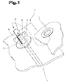
- a first embodiment of a closure system 5 is shown, which is basically used for a variety of commodities.
- the closure system 5 is shown as an application to a garment.
- the garment is closed by means of a zipper 1, the slider 2 of which serves as a support for the closure system 5, by which the garment is held together and fastened.
- the zipper handle 3 fastened to the slider 2 assumes the button function by being guided and folded over by an opening, for example a buttonhole or eyelet, created on the item of clothing to be closed.
- the zipper handle 3 consists of two interconnected elements 3a, 3b, which can be set and fixed at an angle of 90 ° to each other.
- the slider 2 is adapted in its function and size so that it serves in addition to its original function in addition as a carrier of the zipper handle 3, the two interconnected elements 3a, 3b, up to an angle of 90 ° and, if necessary, on it out to each other and can be fixed, there is.
- the slide 2 or closer is designed in size so that it serves as a counterpart and stop to the closure piece 6, for example an eyelet or a buttonhole embroidered.
- the two-part zipper handle 3 after passing through the opening of the clothing counterpart to be closed, is folded and locked at an angle of up to 90 ° and, if necessary, beyond.
- the locking is effected by a mechanically generated resistance, for example by a resistance generated by spring, by a Einrastsystem by means of a spring-biased ball or other closure mechanisms and Einrastsysteme, or by the outgoing from the body of the clothing wearer pressure.
- the slide 2 or closer is designed so that it partially takes over the handle function and is connected to a zipper handle 3 so that a part of the slider 2 is guided with the zipper handle 3 through the opening of the clothing counterpart to be closed and the zipper handle 3 as individual, connected to the slider 2 element at an angle up to 90 ° and, if necessary, in addition folded over and locked.
- This folding and locking the slider 2 is kept positioned in this closed position of the zipper 1 on the commodity.
- the zipper handle 3 can be secured in the closed state by a plate 4, which can serve as a support plate for the attachment of various decorative items, such as art ornaments, motifs, sculptures, stones, at the same time. These can be individually attached to the support plate as a clothing accessory.
- the garment accessory may also be referred to as the application element 7, as is the case in the description below.
- This plate 4 can either be designed as an accessory or application element 7 itself or serve as a support plate for attachment of accessories or application elements 7.
- the application element 7 or the plate 4 may further be made of a variety of materials, such as. Metal, glass, ceramic, plastic, sintered materials, stone, gemstone and any combination thereof may be formed. Also, the room shape and the appearance can be chosen freely.
- the patch plate 4 prevents the zipper handle 3 from being released from the lock.
- the plate 4 is fastened and secured on the zipper handle 3, for example by means of a spring mechanism, ball bearings, locking mechanisms, locking systems and the like.
- the slider 2 and the zipper handle 3 can be secured in the closed state by the plate 4, which is placed on a part of the slider 2 and the zipper handle 3.
- the article of daily use may in particular be clothing, bags, suitcases, coverings, covers, tarpaulins, mattress covers, or the like.
- the closure system 5 shown here also comprises in this embodiment, in turn, the zipper 1, the slide 2 and the zipper handle 3 with its two elements 3a, 3b and the closure piece 6.
- the zipper 1 can also be arranged on a piece of clothing shown in simplified, in a partial region or partial section of the garment, the closure piece 6, for example in the form an eyelet is positioned.
- the closing process takes place here analogously, as previously detailed in the Fig. 1 to 3 has been described.
- the zipper 1 is closed via the slider 2 in a known manner, wherein the operation is performed by the zipper handle 3.
- the zipper handle 3 is passed through the opening formed by the closure piece 6 and for locking the second element 3b pivoted relative to the first element 3a in an angular position thereto.
- the fact that the longitudinal extent of the second or further element 3b is selected to be longer or larger than the opening diameter of the closure piece 6 results in a locking of the zipper grip 3 with the closure piece 6. In this way, the zipper grip 3 with the slider 2 is connected, in turn, an unwanted loosening or opening of the zipper 1 can be prevented.
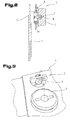
- FIG. 7 to 9 a further and possibly independent embodiment of the closure system 5 is shown, again for like parts, the same reference numerals or component designations as in the preceding Fig. 1 to 6 be used. In order to avoid unnecessary repetition, the detailed description in the previous ones will be used Fig. 1 to 6 referred or referred.
- the closure piece 6 here comprises a hollow profile-shaped or tubular-shaped base part 8, which in turn is connected to the utility object. This is usually done in a stationary arrangement in order to obtain a correspondingly strong, stable seat.
- the base part 8 may have on its side facing the utility object an annular flange 9, which has a planar contact surface for supporting on the utility object.
- the base part 8 can be connected via the annular flange 9 with a ring 10, for example in the form of a riveting operation, so as to form the closure piece 6.
- the riveting process or the components used to form the ring rivets can be arbitrarily selected from the known prior art and used.
- the base part 8 usually has a circular cross-sectional shape, wherein differences in diameter in the direction of its longitudinal axis 11 are possible.
- the base part 8 has a first end 12 facing the article of daily use or the annular flange 9 and a further end 13 which is distanced therefrom.
- the base part 8 and optionally the annular flange 9 are arranged on the side facing away from the zipper 1 side of the commodity, wherein the further or second end 13 of the base part 8 is formed protruding on the side facing away from the zipper 1 side.
- the plate 4 described above is arranged or connected to the base part 8.
- This attachment or holder is preferably on the outside on the side facing away from the longitudinal axis of the base part 8. If the plate 4 itself as an application element 7, in particular as a decorative item, art ornament, motif, stone or clothing accessory formed, so a direct recording and mounting of the plate 4 done on the base part 8.
- the support device 14 for the application element 7 comprises in this embodiment shown here a disk-shaped base plate 15 and at least one connected thereto and in the vertical direction with respect to the base plate 15 extending holding member 16.
- the application element or elements 7 can be fastened or held on the carrying device 14.
- the holding element 16 may preferably be formed as a circumferentially continuously formed wall part in a tubular shape, wherein in addition to the side facing away from the base plate 15, a collar 17 or more collar elements may be provided or may. But it would also be possible, instead of the circumferential wall portion distributed over the circumference arranged holding elements 16 provide, by means of which the application element 7 on the support device 14, in particular the base plate 15, can be fixed or held.
- the one or more holding elements 16 are arranged in the region of the base plate 15 in the region of the opening 18 passing through the base plate 15.
- a latching device 19 is provided between the support device 14 and the base part 8.
- a first locking element 20 is arranged or formed on the base part 8.
- a second latching element 21 is arranged or formed on the carrying device 14, in particular the holding element 16. In this way, the carrying device 14 and subsequently the application element 7 can be kept positioned in at least one direction aligned in the axial direction of the base part 8.
- the second latching element 21 is arranged or formed on the application element 7. This is illustrated with the reference numeral 21, which is shown in dashed lines, in the application element 7.
- the application element 7 also has an opening 22 in its center, which is designed in such a way that it can either be placed directly on the holding element 16 on the outside or fastened or held on the base part 8 without the carrier 14 being interposed.
- the first locking element 20 is arranged at a side facing away from the closer 2 end of the base part 8 at this or formed.
- the at least second latching element 21 of the latching device 19 is arranged or formed on the support device 14 at a side facing away from the slider 2 end of the holding element 16.
- FIG. 10 a further and possibly independent embodiment of the closure system 5 is shown, again for like parts, the same reference numerals or component designations as in the preceding Fig. 1 to 9 be used. In order to avoid unnecessary repetition, the detailed description in the previous ones will be used Fig. 1 to 9 referred or referred.
- this variant embodiment shown here is similar, as previously in the Fig. 7 to 9 , in particular the Fig. 9 , has been described.
- the at least second latching element 21 of the latching device 19 is arranged on an inner surface 23 of the disk-shaped base plate 15 or formed there.
- this second locking element 21 may be formed either by its own component, which is arranged in the form of a securing ring or the like on the inner surface 23 or part of the base plate 15.
- the support device 14 is applied to the application element 7 arranged thereon by a built-up by a spring element 24 actuating force in the axial direction relative to the base part 8 on the side facing away from the slider 2 side.
- the application element 7 can also be acted upon by a corresponding actuating force by means of the spring element 24 alone on the side of the base part 8 facing away from the slide 2.
- the spring element 24 it is achieved that the carrying device 14 or the application element 7 is pressed solely against the above-described, pivoted element 3b of the zipper handle 3.
- a tense or biased position of the zipper handle 3 in the closed position of the zipper 1 is always achieved.
- closure piece 6 forms, for example, with the annular flange 9 an eyelet, wherein the base part 8 optionally forms a structural unit with the interposition of the annular flange 9 with the ring 10.
- This can also be referred to as a ring rivet or ring eyelet.
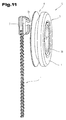
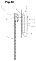
- FIG. 11 and 12 a further and possibly independent embodiment of the closure system 5 is shown, again for like parts, the same reference numerals or component designations as in the preceding Fig. 1 to 10 be used. In order to avoid unnecessary repetition, the detailed description in the previous ones will be used Fig. 1 to 10 referred or referred.
- a further closure system 5 which comprises the zipper 1, the slider 2 and the zipper grip 3.
- the connected to the slider 2 element 3a of the zipper handle 3 is rod-shaped and extends through the closure piece 6, which is optionally arranged stationary on the commodity, as has already been described above.
- the closure member 6 directly the application element 7 is arranged or held without interposition of the support device 14.
- the cross-sectional shape of the application element 7 can be chosen arbitrarily, and here again, as in the embodiments described above, simply a change or replacement of the application elements 7 on the closure piece 6 by the user is possible. This is achieved by the locking device 19 described above.
- the zipper handle 3 here comprises, in addition to the rod-shaped first element 3a, which is movably connected to the slider 2, the further element 3b, which is designed as a preferably annular or partially annular body.
- the further element 3b is hingedly connected to the first element 3a on its side facing away from the slider 2 and pivotally connected thereto.
- the element 3b is flexible and thus elastically deformable in its spatial form.
- the passage of the element 3b can be facilitated by the closure piece 6, since so the ring can be brought into a slightly oval shape.
- the flexibly formed element 3b can return automatically to its original initial shape.
- the flexible deformability of the element 3b can also serve for locking it on or in the closure piece 6, in particular its base part 8.
- the plate 4 and / or the application element 7 and / or the support device 14 for the application element 7 in cooperation with the closure piece 6 and at least one blocking element form a closing or locking device.
- the zipper 1 can be additionally secured secured against unauthorized opening.
- the closure system 5 with the zipper 1, the slider 2 and the zipper handle 3 in the region of the closure piece 6 educate so that only by a person authorized to unlock the locking device is made possible.
- closure system 5 of this or its components has been shown partially unevenly and / or enlarged and / or reduced in size.
Description
Die Erfindung betrifft ein Verschlusssystem mit einem Reißverschluss, einem Schieber sowie einem Reißverschlussgriff, wie dieses im Anspruch 1 beschrieben ist.The invention relates to a closure system with a zipper, a slider and a zipper handle, as described in
Aus der
Ähnliche Verschlusssysteme, bei denen der Schieber des Reißverschlusses mit seinem Reißverschlussgriff an einem am Gebrauchsgegenstand ausgebildeten Verschlussstück gehalten ist, sind beispielsweise in der
Zum Beispiel ist in der
Die
In der
Aus der
Bekleidungsverschlüsse, beispielsweise für Hosen oder Röcke, sind in verschiedensten Formen bekannt. Meist werden die Bekleidungsstücke entweder mit Knöpfen jedweder Art oder mit Reißverschlüssen in Kombination mit Knöpfen und einer dazugehörigen Öffnung im Bekleidungsteil (Knopfloch) verschlossen.Clothing closures, for example for pants or skirts, are known in various forms. Usually the garments are either with buttons of any kind or closed with zippers in combination with buttons and an associated opening in the garment (buttonhole).
Durch das Vorsehen des Verschlusssystems kann auf die Anbringung von Knöpfen, Schließem oder Schnallen zur zusätzlichen Sicherung von Bekleidungsstücken verzichtet werden. Die Bekleidungsstücke werden ausschließlich durch einen Reißverschluss und dem damit verbundenen Schieber samt Reißverschlussgriff (Reißverschlussanhänger) zusammengehalten und befestigt. Hierdurch kann einerseits auf das zusätzliche Anbringen von Knöpfen verzichtet werden und gleichzeitig das Phänomen offener Reißverschlüsse im Tragegebrauch vermieden werden. Dies hilft mit, peinliche Unannehmlichkeiten dieser Art zu vermeiden.By providing the closure system can be dispensed with the attachment of buttons, Schließem or buckles for additional security of garments. The garments are held together and fastened exclusively by a zipper and the associated slider with zipper pull (zipper puller). As a result, on the one hand to dispense with the additional attachment of buttons and at the same time the phenomenon of open zippers are avoided in wear use. This helps to avoid embarrassing inconveniences of this kind.
Der vorliegenden Erfindung liegt die Aufgabe zugrunde, ein Verschlusssystem zu schaffen, welches zusätzlich zu seiner Sicherung gegen unbeabsichtigtes Öffnen des Reißverschlusses einfach und individuell an unterschiedliche Einsatzzwecke bzw. Tragebedingungen selbst durch den Benutzer angepasst werden kann, um diesem ein hohes Ausmaß an Gestaltungsmöglichkeit zur Verfügung zu stellen.The present invention has for its object to provide a closure system, which in addition to its protection against unintentional opening of the zipper can be easily and individually adapted to different purposes or wearing conditions even by the user to this a high degree of design options available put.
Diese Aufgabe der Erfindung wird durch die Merkmale des Anspruches 1 gelöst. Der sich durch die Merkmale des Anspruches 1 ergebende Vorteil liegt darin, dass so nach dem gesicherten Verschluss und der Halterung des Schiebers über den Reißverschlussgriff am Verschlussstück des Gebrauchsgegenstandes an der vom Schieber abgewendeten Seite des Gebrauchsgegenstandes ein plattenförmiger Körper angeordnet werden kann. So kann z.B. mit einem einfachen Verbindungsvorgang das Anbringen und damit auch die individuelle Gestaltung des Verschlusssystems für den Benutzer einfach ermöglicht werden. Durch das Vorsehen der Platte kann aber darüber hinaus auch noch eine zusätzliche Sicherung des Reißverschlussgriffs in seiner Sperrstellung im Bereich des Verschlussstücks erreicht werden. Darüber hinaus kann so aber auch eine Abdeckung bzw. Abschirmung des Verschlusssystems im Bereich des Verschlussstücks erzielt werden. Durch den Einsatz unterschiedlichster Rastsysteme kann eine einfache Wechselmöglichkeit der Platte je nach Anwendungsfall bzw. Einsatzzweck ermöglicht werden, wodurch eine oder mehrere entsprechend ausgestalteten Platten gewählt werden können, um so einfach das individuelle Aussehen des Verschlusssystems verändern und an die Wünsche des Benutzers anpassen zu können. So wäre es beispielsweise möglich, die Farbe, die Form sowie die Gestaltung und das optische Aussehen der Platte an weitere Bekleidungsaccessoires wie z.B. Gürtel, Brille, Handtasche, Schuhe oder dergleichen individuell an den jeweiligen Bedarfsfall anpassen zu können. Durch die Ausbildung eines Basisteils es möglich, eine weitere Gestaltungsmöglichkeit bereit zu stellen, wobei durch das Anordnen der Platte direkt am Verschlussstück für das Öffnen des Verschlusssystems die Platte nicht mehr vom Verschlussstück abgenommen werden muss. In diesem Anwendungsfall kann ein optisch ansprechendes Aussehen erreicht werden, da die Platte den Basisteil zumindest radial überragt und damit sehr oberflächennah zum Gebrauchsgegenstand angeordnet werden kann. In axialer Richtung bezüglich des Basisteils gesehen wird die Platte so dimensioniert, dass diese bevorzugt mit dem Basisteil auf der vom Schieber abgewendeten Seite in etwa bündig abschließt bzw. kurz vor diesem endet oder aber auch das Ende in axialer Richtung geringfügig überragt. Bei einer ebenflächigen bzw. rückspringenden Anordnung der Platte kann diese vor Beschädigungen ausgehend vom Reißverschlussgriff geschützt werden. Damit kann ein direkter Kontakt des Reißverschlussgriffes mit der Platte in seiner verrasteten Stellung vermieden werden. Durch die Ausgestaltung der Platte als Applikationselement wird erreicht, dass so ein hohes Ausmaß an Gestaltungsmöglichkeiten für den Benutzer und damit eine individuelle Anpassung an seine Bedürfnisse geschaffen wird.This object of the invention is solved by the features of
Vorteilhaft ist auch eine weitere Ausführungsform nach Anspruch 2, da damit durch das Verbinden bzw. Halten der Platte am Reißverschlussgriff dieser zusätzlich vor einem ungewollten Öffnen gesichert werden kann. Darüber hinaus wird aber auch eine verbesserte Optik geschaffen, da kein direkter Sichtkontakt zum Verschlusssystem, insbesondere dem Verschlussstück, ermöglicht wird. Weiters kann damit aber auch die Verletzungsgefahr herabgesetzt werden.Also advantageous is a further embodiment according to
Vorteilhaft ist weiters eine Ausbildung nach Anspruch 3, da dadurch für den Benutzer eine noch höhere Gestaltungsmöglichkeit für die unterschiedlichsten Anwendungsfälle geschaffen wird. Damit können noch zusätzliche Gestaltungsmöglichkeiten geschaffen werden, da damit die Kombinationsvielfalt weiter erhöht werden kann. So kann ein Baukastensystem geschaffen werden, welches es dem Benutzer ermöglicht, nicht nur die als Trägerplatte ausgebildete Platte, sondern auch eine Vielzahl unterschiedlicher Applikationselemente damit kombinieren zu können.A further advantage is an embodiment according to
Vorteilhaft ist auch eine Weiterbildung nach Anspruch 4, da damit die Möglichkeit geschaffen wird, auch ansonsten leicht zu beschädigende Applikationselemente am Basisteil anzubringen bzw. dort zu halten. So kann die Tragvorrichtung auch als Fassung bzw. Einfassung bezeichnet werden, wie dies in der Schmuckindustrie bei Steinen oder Edelsteinen häufig der Fall istAlso advantageous is a development according to
Bei der Ausgestaltung nach Anspruch 5 ist von Vorteil, dass so im Einsatzfall bzw. bei der Verwendung eine gesicherte Halterung des Applikationselements gegebenenfalls unter Zwischenschaltung der Tragvorrichtung am Basisteil des Verschlussstückes erzielt werden kann. Darüber hinaus kann aber so ein werkzeugloser Wechsel des Applikationselements bzw. der Platte vom Anwender bzw. Benutzer durchgeführt werden.In the embodiment according to
Durch die Weiterbildung nach Anspruch 6 wird erreicht, dass so gleich bei der Herstellung des Basisteils an diesem einfach und in einem Arbeitsgang das Rastelement ausgebildet werden kann. Dieses Rastelement kann als Wulst bzw. Verdickung ausgebildet sein, wodurch auch in diesem Bereich eine zusätzliche optische Gestaltungsmöglichkeit bereits am Basisteil ermöglicht wird.Through the development according to
Durch die Ausbildung nach Anspruch 7 können auch sensible bzw. bruchgefährdete Applikationselemente eingesetzt werden, da die Tragvorrichtung eine gewisse Stütz- und/oder Haltefunktion für derartige Bauteile ausübt.Due to the design according to
Vorteilhaft ist auch eine Ausbildung nach Anspruch 8, da damit durch das oder die Halteelemente der Tragvorrichtung eine Doppelfunktion ausgeübt werden kann. Damit dient das Halteelement nicht nur zur Positionierung bzw. Fixierung des Applikationselementes an der Tragvorrichtung sondern bildet im Zusammenwirken mit dem am Basisteil angeordneten ersten Rastelement die Rastvorrichtung für das an der Tragvorrichtung befestigte Applikationselement aus.Also advantageous is an embodiment according to
Gemäß einer Ausbildung, wie im Anspruch 9 beschrieben, kann eine weitere Raststellung zwischen dem Applikationselement bzw. dessen Tragvorrichtung und dem Basisteil des Ver schlussstücks erreicht werden. Je nach axialer Länge des Basisteils kann so eine Distanzierung der scheibenförmig ausgebildeten Grundplatte von der vom Reißverschluss abgewendeten Seite des Gebrauchsgegenstandes erzielt werden. Damit kann aufgrund dieser Distanzierung zwischen der Grundplatte und dem Gebrauchsgegenstand zumindest eine weitere Platte bzw. ein weiteres Applikationselement am Basisteil angeordnet werden, wobei die Verrastung bzw. Halterung durch die Tragvorrichtung erfolgen kann.According to one embodiment, as described in claim 9, a further detent position between the application element or its support device and the base part of the Ver be reached. Depending on the axial length of the base part, a distancing of the disk-shaped base plate from the side of the object of use facing away from the zipper can thus be achieved. Thus, due to this distancing between the base plate and the utility object at least one further plate or a further application element are arranged on the base part, wherein the latching or mounting can be carried out by the support device.
Dabei erweist sich eine Ausgestaltung nach Anspruch 10 vorteilhaft, weil dadurch das Applikationselement bzw. die Tragvorrichtung auf die vom Reißverschluss abgewendete Seite des Gebrauchsgegenstandes mit einer Stellkraft beaufschlagt ist, wodurch bei Anlage des Reißverschlussgriffs am Applikationselement der Schieber an die dem Reißverschluss zugewendete Seite des Gebrauchsgegenstandes gedrückt wird. Durch diese Vorspannung wird ein unbeabsichtigtes Lösen des Reißverschlussgriffs in seiner Sperrstellung zusätzlich verhindert.In this case, an embodiment according to claim 10 proves advantageous because thereby the application element or the support device is acted upon on the side facing away from the zipper of the utensil with a force, whereby pressed when applying the zipper handle on the application element, the slider to the zippered side facing the commodity becomes. By this bias inadvertent release of the zipper handle is additionally prevented in its locked position.
Es wäre aber auch eine Ausbildung, wie diese im Anspruch 11 beschrieben ist möglich, da so über einen einfachen Verbindungsvorgang, wie dieser bereits bei bekannten Nietverbindungen eingesetzt wird, eine kostengünstige Befestigungsmöglichkeit am Gebrauchsgegenstand geschaffen wird.But it would also be an education, as described in
Schließlich ist aber auch eine Ausbildung, wie im Anspruch 12 beschrieben möglich, da so das Verschlusssystem vor einer unberechtigten Öffnung geschützt werden kann.Finally, however, an embodiment as described in
Zum besseren Verständnis der Erfindung wird diese anhand der nachfolgenden Figuren näher erläutert.For a better understanding of the invention, this will be explained in more detail with reference to the following figures.
Es zeigen jeweils in stark vereinfachter, schematischer Darstellung:
- Fig. 1
- eine mögliche Ausbildung eines Verschlusssystems, in schaubildlicher Darstellung;
- Fig. 2
- ein weiteres Verschlusssystem mit einer im Bereich des Verschlussstücks zusätzlich angeordneten Platte, in Seitenansicht geschnitten;
- Fig. 3
- das Verschlusssystem nach
Fig. 2 vor dem Anbringen der Platte, in schaubildlicher Darstellung; - Fig. 4
- eine andere mögliche Ausbildung eines Verschlusssystems, bei noch geöffnetem Reißverschluss, in schaubildlicher Darstellung;
- Fig. 5
- das Verschlusssystem nach
Fig. 4 , während des Schließvorganges, in schaubildlicher Darstellung; - Fig. 6
- das Verschlusssystem nach den
Fig. 4 und 5 in der Schließstellung, in schaubildlicher Darstellung; - Fig. 7
- ein am Gebrauchsgegenstand angebrachtes Verschlussstück, in Seitenansicht geschnitten;
- Fig. 8
- ein Applikationselement sowie eine Tragvorrichtung vor deren Fügevorgang, in Seitenansicht geschnitten;
- Fig. 9
- das mittels der Tragvorrichtung am Verschlussstück gehaltene Applikationselement nach den
Fig. 7 , in Seitenansicht geschnitten;und 8 - Fig. 10
- eine weitere mögliche Ausbildung eines Applikationselements sowie einer Tragvorrichtung, mit einem dazwischen angeordneten Federelement, in Seitenansicht geschnitten;
- Fig. 11
- ein weiteres mögliches Verschlusssystem mit Verschlussstück und verrastetem Reißverschlussgriff, in schaubildlicher Darstellung;
- Fig. 12
- das Verschlusssystem nach
Fig. 11 , in Seitenansicht geschnitten.
- Fig. 1
- a possible design of a closure system, in perspective view;
- Fig. 2
- a further closure system with a plate additionally arranged in the region of the closure piece, cut in side view;
- Fig. 3
- the locking system after
Fig. 2 before attaching the plate, in a diagrammatic view; - Fig. 4
- another possible design of a closure system, with the zipper still open, in a perspective view;
- Fig. 5
- the locking system after
Fig. 4 during the closing process, in a diagrammatic representation; - Fig. 6
- the closure system after the
4 and 5 in the closed position, in a perspective view; - Fig. 7
- a piece attached to the utility item, cut in side view;
- Fig. 8
- an application element and a support device before the joining process, cut in side view;
- Fig. 9
- held by means of the support device on the closure piece application element after the
FIGS. 7 and 8 , cut in side view; - Fig. 10
- another possible embodiment of an application element and a support device, with a spring element arranged therebetween, cut in side view;
- Fig. 11
- Another possible locking system with locking piece and latched zipper handle, in perspective view;
- Fig. 12
- the locking system after
Fig. 11 , cut in side view.
Einführend sei festgehalten, dass in den unterschiedlich beschriebenen Ausführungsformen gleiche Teile mit gleichen Bezugszeichen bzw. gleichen Bauteilbezeichnungen versehen werden, wobei die in der gesamten Beschreibung enthaltenen Offenbarungen sinngemäß auf gleiche Teile mit gleichen Bezugszeichen bzw. gleichen Bauteilbezeichnungen übertragen werden können. Auch sind die in der Beschreibung gewählten Lageangaben, wie z.B. oben, unten, seitlich usw. auf die unmittelbar beschriebene sowie dargestellte Figur bezogen und sind diese Lageangaben bei einer Lageänderung sinngemäß auf die neue Lage zu übertragen.By way of introduction, it should be noted that in the differently described embodiments, the same parts are provided with the same reference numerals or the same component names, wherein the disclosures contained in the entire description can be mutatis mutandis to the same parts with the same reference numerals or component names. Also, the location information selected in the description, such as above, below, laterally, etc. related to the immediately described and illustrated figure and these position information in a change in position mutatis mutandis to transfer to the new location.
In der
Das Bekleidungsstück wird mittels eines Reißverschlusses 1 verschlossen, dessen Schieber 2 als Träger des Verschlusssystems 5 dient, durch das das Bekleidungsstück zusammengehalten und befestigt wird. Der am Schieber 2 befestigte Reißverschlussgriff 3 übernimmt die Knopffunktion, indem er durch eine an dem zu verschließenden Bekleidungsstück geschaffene Öffnung, beispielsweise ein Knopfloch oder eine Öse, geführt wird und umgelegt wird. Der Reißverschlussgriff 3 besteht aus zwei miteinander verbundenen Elementen 3a, 3b, die in einem Winkel von 90° zueinander gestellt und fixiert werden können. Hierdurch wird das Bekleidungsstück bzw. die Öse wie durch einen Knopf festgehalten und lässt sich ohne einen bewusst durchgeführten mechanischen Aufwand nicht lösen.The garment is closed by means of a
Der Schieber 2 ist in seiner Funktion und Größe so angepasst, dass er neben seiner ursprünglichen Funktion zusätzlich als Träger des Reißverschlussgriffs 3 dient, der aus zwei miteinander verbundenen Elementen 3a, 3b, die bis zu einem Winkel von 90° und, sofern erforderlich, darüber hinaus zueinander gestellt und fixiert werden können, besteht. Der Schieber 2 bzw. Schließer ist in seiner Größe so gestaltet, dass er als Gegenstück und Halt zum Verschlussstück 6, beispielsweise einer Öse oder einem eingefassten Knopfloch, dient. Der zweigeteilte Reißverschlussgriff 3 wird nach dem Durchführen durch die Öffnung des zu verschließenden Bekleidungsgegenstücks im Winkel bis zu 90° und, sofern erforderlich, darüber hinaus umgelegt und verriegelt. Die Verriegelung erfolgt durch einen mechanisch erzeugten Widerstand, beispielsweise durch einen mittels Feder erzeugten Widerstand, durch ein Einrastsystem mittels einer mit Feder vorgespannten Kugel oder durch andere Verschlussmechanismen und Einrastsysteme, oder durch den vom Körper des Bekleidungsträgers ausgehenden Druck.The
Der Schieber 2 bzw. Schließer ist so gestaltet, dass er teilweise die Grifffunktion mit übernimmt und mit einem Reißverschlussgriff 3 so verbunden ist, dass ein Teil des Schiebers 2 mit dem Reißverschlussgriff 3 durch die Öffnung des zu verschließenden Bekleidungsgegenstücks geführt wird und der Reißverschlussgriff 3 als einzelnes, mit dem Schieber 2 verbundenes Element im Winkel bis zu 90° und, sofern erforderlich, darüber hinaus umgelegt und verriegelt wird. Durch dieses Umlegen und Verriegeln ist der Schieber 2 in dieser geschlossenen Stellung des Reißverschlusses 1 am Gebrauchsgegenstand positioniert gehalten.The
Zusätzlich kann der Reißverschlussgriff 3 im verschlossenen Zustand durch eine Platte 4 gesichert werden, die gleichzeitig als Trägerplatte für das Anbringen diverser Ziergegenstände, beispielsweise Kunstverzierungen, Motive, Plastiken, Steine, dienen kann. Diese können individuell an der Trägerplatte als Bekleidungsaccessoire befestigt werden. Das Bekleidungsaccessoire kann auch als Applikationselement 7 bezeichnet werden, wie dies in der nachfolgenden Beschreibung der Fall ist.In addition, the zipper handle 3 can be secured in the closed state by a
Damit ist zumindest in der geschlossenen Stellung des Reißverschlusses 1 im Bereich des Verschlussstücks 6 zumindest eine Platte 4 angeordnet. Diese Platte 4 kann entweder selbst als Accessoire bzw. Applikationselement 7 ausgebildet sein oder aber als Trägerplatte zur Befestigung von Accessoires bzw. Applikationselementen 7 dienen. Das Applikationselement 7 bzw. die Platte 4 kann weiters aus den unterschiedlichsten Werkstoffen, wie z.B. Metall, Glas, Keramik, Kunststoff, Sinterwerkstoffen, Stein, Edelstein sowie einer beliebigen Kombination daraus gebildet sein. Auch kann die Raumform sowie das Erscheinungsbild frei gewählt werden.Thus, at least in the closed position of the
So wird der Reißverschlussgriff 3 im verschlossenen Zustand durch die Platte 4, die auf den Reißverschlussgriff 3 aufgesetzt wird, gesichert. Durch die aufgesetzte Platte 4 wird verhindert, dass sich der Reißverschlussgriff 3 aus der Verriegelung lösen kann. Die Platte 4 wird auf dem Reißverschlussgriff 3 befestigt und gesichert, beispielsweise mittels Federmechanismus, Kugellager, Verschlussmechanismen, Einrastsysteme und dergleichen.Thus, the zipper handle 3 in the closed state by the
Weiters kann der Schieber 2 und der Reißverschlussgriff 3 im verschlossenen Zustand durch die Platte 4, die auf einen Teil des Schiebers 2 und den Reißverschlussgriff 3 aufgesetzt wird, gesichert werden.Furthermore, the
Dadurch, dass der Reißverschlussgriff (3) im geschlossenen Zustand mit dem Gegenstück (durch Hindurchführung durch das Knopfloch oder die Öse) des Bekleidungsstücks verbunden ist, ist es ausgeschlossen, dass sich der Reißverschluss (1) während des Tragens unerwünscht öffnen kann, da er am oberen Ende des geschlossenen Reißverschlusses (1) am Bekleidungsstück fixiert ist.The fact that the zipper handle (3) in the closed state with the counterpart (by passing through the buttonhole or eyelet) is connected to the garment, it is impossible that the zipper (1) can open undesirably during wear, since he upper end of the closed zipper (1) is fixed to the garment.
Es sei hier angemerkt, dass die Anwendung nicht auf Reißverschlüsse 1 im Bekleidungsbereich beschränkt ist, sondern auch für industriell genutzte Verschlusssysteme mittels Reißverschluss Anwendung findet.It should be noted here that the application is not limited to
Bei der Herstellung von Bekleidungsstücken, wie z.B. Hosen und Röcken, kann auf einen Produktionsvorgang wie das Anbringen von Knöpfen oder anderen Verschlussmechanismen verzichtet werden, was zu Einsparungen in der Produktion sowie zur Fehlervermeidung beim Produktionsprozess beiträgt.In the manufacture of garments, e.g. Pants and skirts, can be dispensed with a production process such as the attachment of buttons or other closure mechanisms, which contributes to savings in production and error prevention in the production process.
Bei dem Gebrauchsgegenstand kann es sich insbesondere um Bekleidungsstücke, Taschen, Koffer, Verkleidungen, Abdeckungen, Planen, Matratzenüberzüge, oder dgl. handeln.The article of daily use may in particular be clothing, bags, suitcases, coverings, covers, tarpaulins, mattress covers, or the like.
In den
Das hier gezeigte Verschlusssystem 5 umfasst auch bei diesem Ausführungsbeispiel wiederum den Reißverschluss 1, den Schieber 2 sowie den Reißverschlussgriff 3 mit seinen beiden Elementen 3a, 3b sowie das Verschlussstück 6. Der Reißverschluss 1 kann auch wiederum an einem vereinfacht dargestellten Bekleidungsstück angeordnet sein, wobei in einem Teilbereich bzw. Teilabschnitt des Bekleidungsstücks das Verschlussstück 6 beispielsweise in Form einer Öse positioniert angeordnet ist. Der Schließvorgang erfolgt hier analog, wie dies bereits zuvor detailliert in den
Zuerst wird der Reißverschluss 1 über den Schieber 2 in bekannter Weise verschlossen, wobei die Betätigung durch den Reißverschlussgriff 3 erfolgt. Nach dem Verbinden der Reißverschlusselemente durch den Schieber 2 wird der Reißverschlussgriff 3 durch die vom Verschlussstück 6 ausgebildete Öffnung hindurchgeführt und zum Verriegeln das zweite Element 3b relativ gegenüber dem ersten Element 3a in eine dazu winkelige Lage verschwenkt. Dadurch, dass die Längserstreckung des zweiten bzw. weiteren Elements 3b länger bzw. größer gewählt ist als der Öffnungsdurchmesser des Verschlussstücks 6, kommt es hier zu einer Verriegelung des Reißverschlussgriffs 3 mit dem Verschlussstück 6. Da auf diese Weise der Reißverschlussgriff 3 mit dem Schieber 2 verbunden ist, kann auch hier wiederum ein ungewolltes Lösen bzw. Öffnen des Reißverschlusses 1 verhindert werden.First, the
In den
So ist in der
Der Basisteil 8 weist zumeist eine kreisrunde Querschnittsform auf, wobei Durchmesserunterschiede in Richtung seiner Längsachse 11 möglich sind.The
Der Basisteil 8 weist in Richtung der Längsachse 11 gesehen, ein dem Gebrauchsgegenstand bzw. dem Ringflansch 9 zugewendetes, erstes Ende 12 sowie ein davon distanziertes, weiteres Ende 13 auf. Der Basisteil 8 sowie gegebenenfalls der Ringflansch 9 sind auf der vom Reißverschluss 1 abgewendeten Seite des Gebrauchsgegenstandes angeordnet, wobei das weitere bzw. zweite Ende 13 des Basisteils 8 auf die vom Reißverschluss 1 abgewendete Seite vorragend ausgebildet ist.Seen in the direction of the
Weiters ist es möglich, dass am Basisteil 8 die zuvor beschriebene Platte 4 angeordnet bzw. damit verbunden ist. Diese Befestigung bzw. Halterung erfolgt bevorzugt außenseitig auf der von der Längsachse abgewendeten Seite des Basisteils 8. Ist die Platte 4 selbst als Applikationselement 7, insbesondere als Ziergegenstand, Kunstverzierung, Motiv, Stein oder Bekleidungsaccessoire ausgebildet, kann so eine direkte Aufnahme und Halterung der Platte 4 am Basisteil 8 erfolgen.Furthermore, it is possible that the
In den
Die Tragvorrichtung 14 für das Applikationselement 7 umfasst bei diesem hier gezeigten Ausführungsbeispiel eine scheibenförmig ausgebildete Grundplatte 15 sowie zumindest ein damit verbundenes und sich in senkrechter Richtung bezüglich der Grundplatte 15 erstreckendes Halteelement 16. Bevorzugt ist das bzw. sind die Halteelemente 16 bezüglich der inneren Öffnung der Grundplatte 15 in Axialrichtung dazu ausgerichtet. Mittels des Halteelements 16 kann das oder die Applikationselemente 7 an der Tragvorrichtung 14 befestigt bzw. gehalten sein.The
Unabhängig davon wäre es aber auch möglich, lediglich die scheibenförmig ausgebildete Grundplatte 15 zu verwenden und das oder die Applikationselemente 7 über eine stoffschlüssige Verbindung, wie beispielsweise eine Klebeverbindung oder dergleichen miteinander zu verbinden.Regardless, it would also be possible to use only the disc-shaped
Das Halteelement 16 kann bevorzugt als über den Umfang durchlaufend ausgebildeter Wandteil in rohrförmiger Form ausgebildet sein, wobei zusätzlich auf der von der Grundplatte 15 abgewendeten Seite ein Bund 17 bzw. mehrere Bundelemente vorgesehen sein kann bzw. können. Es wäre aber auch möglich, anstatt des umlaufenden Wandteils nur über den Umfang verteilt angeordnete Halteelemente 16 vorzusehen, mittels welcher das Applikationselement 7 an der Tragvorrichtung 14, insbesondere der Grundplatte 15, befestigt bzw. gehalten werden kann.The holding
Das oder die Halteelemente 16 sind im Bereich der Grundplatte 15 im Bereich der die Grundplatte 15 durchsetzenden Öffnung 18 angeordnet.The one or
Die zusammengefügte Stellung des Applikationselements 7 mit der Tragvorrichtung 14 ist aus der
Wie nun aus dieser verrasteten Stellung der
Wäre das Applikationselement 7 alleinig und ohne der Tragvorrichtung 14 am Basisteil 8 angeordnet, ist dann das zweite Rastelement 21 am Applikationselement 7 angeordnet bzw. ausgebildet. Dies ist mit dem in strichlierten Linien eingetragen Bezugszeichen 21 beim Applikationselement 7 veranschaulicht.If the
Das Applikationselement 7 weist in seinem Zentrum ebenfalls eine Öffnung 22 auf, welche derart ausgebildet ist, dass diese entweder direkt außenseitig auf das Haltelement 16 aufgesetzt werden kann oder ohne Zwischenschaltung der Tragvorrichtung 14 am Basisteil 8 befestigt bzw. daran gehalten werden kann.The
Somit ist das erste Rastelement 20 an einem vom Schließer 2 abgewendeten Ende des Basisteils 8 an diesem angeordnet bzw. ausgebildet. Das zumindest zweite Rastelement 21 der Rastvorrichtung 19 ist an der Tragvorrichtung 14 an einem vom Schieber 2 abgewendeten Ende des Halteelements 16 angeordnet bzw. ausgebildet.Thus, the
In der
Diese hier gezeigte Ausführungsvariante ist ähnlich ausgebildet, wie dies bereits zuvor in den
Weiters ist in der
Ist keine Tragvorrichtung 14 vorgesehen, kann aber unabhängig davon aber auch das Applikationselement 7 alleinig mittels des Federelements 24 auf die vom Schieber 2 abgewendete Seite des Basisteils 8 mit einer entsprechenden Stellkraft beaufschlagt werden. Durch das Federelement 24 wird erreicht, dass die Tragvorrichtung 14 bzw. das Applikationselement 7 alleinig gegen das zuvor beschriebene, verschwenkte Element 3b des Reißverschlussgriffs 3 gedrückt wird. Damit wird stets eine gespannte bzw. vorgespannte Stellung des Reißverschlussgriffs 3 in der geschlossenen Stellung des Reißverschlusses 1 erzielt.If no carrying
Das in den
In den
Auch hier ist ein weiteres Verschlusssystem 5 gezeigt, welches den Reißverschluss 1, den Schieber 2 sowie den Reißverschlussgriff 3 umfasst. Das mit dem Schieber 2 verbundene Element 3a des Reißverschlussgriffes 3 ist stangenförmig ausgebildet und durchragt das Verschlussstück 6, welches gegebenenfalls am Gebrauchsgegenstand feststehend angeordnet ist, wie dies bereits zuvor beschrieben worden ist.Here too, a
Weiters ist bei diesem Ausführungsbeispiel gezeigt, dass am Verschlussstück 6 direkt das Applikationselement 7 ohne Zwischenschaltung der Tragvorrichtung 14 angeordnet bzw. gehalten ist. Die Querschnittsform des Applikationselements 7 kann beliebig gewählt werden, wobei auch hier wiederum, wie bei den zuvor beschriebenen Ausführungsbeispielen, einfach ein Wechsel bzw. Austausch der Applikationselemente 7 am Verschlussstück 6 durch den Benutzer selbst möglich ist. Dies wird durch die zuvor beschriebene Rastvorrichtung 19 erreicht.Furthermore, it is shown in this embodiment that the
Der Reißverschlussgriff 3 umfasst hier zusätzlich zu dem stangenförmig ausgebildeten ersten Element 3a, welches mit dem Schieber 2 bewegungsverbunden ist, das weitere Element 3b, welches als bevorzugt ringförmiger oder teilringförmiger Körper ausgebildet ist. Das weitere Element 3b ist mit dem ersten Element 3a auf seiner vom Schieber 2 abgewendeten Seite gelenkig bzw. schwenkbar damit verbunden. Bei diesem Ausführungsbeispiel ist es vorteilhaft, wenn das Element 3b flexibel und somit in seiner Raumform elastisch umformbar ist. Damit kann das Hindurchführen des Elements 3b durch das Verschlussstück 6 erleichtert werden, da so der Ring in eine leicht ovale Form gebracht werden kann. Nach dem Hindurchführen durch die innere Öffnung des Verschlussstücks 6 kann sich das flexibel ausgebildete Element 3b wieder in seine ursprüngliche Ausgangsform selbsttätig zurückstellen. So kann bereits in dieser ursprünglichen Raumform eine gewisse Haltewirkung und damit verbunden, ein unbeabsichtigtes Öffnen des Reißverschlusses 1 verhindert werden. Die flexible Verformbarkeit des Elements 3b kann aber auch zum Arretieren desselben am bzw. im Verschlussstück 6, insbesondere dessen Basisteil 8, dienen.The zipper handle 3 here comprises, in addition to the rod-shaped
Dadurch wird es möglich, für den Verschlussvorgang des Gebrauchsgegenstandes das Verschlussstück 6 gegebenenfalls mit den daran angeordneten bzw. gehaltenen Applikationselementen 7 nach dem Schließen des Reißverschlusses 1 so zu positionieren, dass der Reißverschlussgriff 3 mit seinem weiteren Element 3b durch die innere Öffnung des Verschlussstücks 6 hindurchgeführt werden kann. Das erste Element 3a des Reißverschlussgriffs 3 wird dabei ebenfalls zumindest zum Teil durch das Verschlussstück 6 hindurchgeführt. Nach diesem Verschlussvorgang und dem damit verbundenen Halten des Schiebers 2 relativ bezüglich des Verschlussstücks 6 kann das weitere Element 3b in eine in etwa rechtwinkelige Lage bezüglich der Längsachse 11 des Basisteils 8 des Verschlussstücks 6 verbracht werden. Im Zuge dieses Umklappens des weiteren Elements 3b kann dieses zusätzlich noch an der Tragvorrichtung 14 und/oder dem Applikationselement 7 verrastet gehalten werden.This makes it possible, for the closing process of the article of daily use, to position the
Es wäre aber auch eine Kombination der Ausführungsform gemäß der
Darüber hinaus wäre es aber auch noch möglich, dass die Platte 4 und/oder das Applikationselement 7 und/oder die Tragvorrichtung 14 für das Applikationselement 7 im Zusammenwirken mit dem Verschlussstück 6 sowie zumindest einem Sperrelement eine Schließ- bzw. Sperrvorrichtung bilden. So kann mit dem Vorsehen eines oder mehrerer Sperrelemente erreicht werden, dass der Reißverschluss 1 zusätzlich vor einem unberechtigten Öffnen gesichert abgesperrt werden kann. Dies wäre eine mögliche weitere Aufgabe der Erfindung, nämlich das Verschlusssystem 5 mit dem Reißverschluss 1, dem Schieber 2 sowie dem Reißverschlussgriff 3 im Bereich des Verschlussstücks 6 so weiterzubilden, dass nur durch eine dazu berechtigte Person das Aufschließen der Sperrvorrichtung ermöglicht wird. Dies wäre z.B. bei Matratzenüberzügen im Gefängnisbereich, bei Auto- und LKW-Planen oder dgl. ein Einsatzgebiet.In addition, it would also be possible that the
Die Ausführungsbeispiele zeigen mögliche Ausführungsvarianten des Verschlusssystems 5, wobei an dieser Stelle bemerkt sei, dass die Erfindung nicht auf die speziell dargestellten Ausführungsvarianten derselben eingeschränkt ist, sondern vielmehr auch diverse Kombinationen der einzelnen Ausführungsvarianten untereinander möglich sind und diese Variationsmöglichkeit aufgrund der Lehre zum technischen Handeln durch gegenständliche Erfindung im Können des auf diesem technischen Gebiet tätigen Fachmannes liegt.The embodiments show possible embodiments of the
Weiters können auch Einzelmerkmale oder Merkmalskombinationen aus den gezeigten und beschriebenen unterschiedlichen Ausführungsbeispielen für sich eigenständige, erfinderische oder erfindungsgemäße Lösungen darstellen.Furthermore, individual features or combinations of features from the different exemplary embodiments shown and described can also represent independent, inventive or inventive solutions.
Die den eigenständigen erfinderischen Lösungen zugrundeliegende Aufgabe kann der Beschreibung entnommen werden.The task underlying the independent inventive solutions can be taken from the description.
Sämtliche Angaben zu Wertebereichen in gegenständlicher Beschreibung sind so zu verstehen, dass diese beliebige und alle Teilbereiche daraus mitumfassen, z.B. ist die Angabe 1 bis 10 so zu verstehen, dass sämtliche Teilbereiche, ausgehend von der unteren Grenze 1 und der oberen Grenze 10 mit umfasst sind, d.h. sämtliche Teilbereiche beginnen mit einer unteren Grenze von 1 oder größer und enden bei einer oberen Grenze von 10 oder weniger, z.B. 1 bis 1,7, oder 3,2 bis 8,1, oder 5,5 bis 10.All statements of value ranges in the present description should be understood to include any and all sub-ranges thereof, e.g. is the
Vor allem können die einzelnen in den
Der Ordnung halber sei abschließend darauf hingewiesen, dass zum besseren Verständnis des Aufbaus Verschlusssystems 5 dieses bzw. dessen Bestandteile teilweise unmaßstäblich und/oder vergrößert und/oder verkleinert dargestellt wurden.For the sake of the order, it should finally be pointed out that, for a better understanding of the construction, the
- 11
- Reißverschlusszipper
- 22
- Schieberpusher
- 33
- Reißverschlussgriffzip pull
- 3a3a
- Elementelement
- 3b3b
- Elementelement
- 44
- Platteplate
- 55
- Verschlusssystemlocking system
- 66
- Verschlussstückclosing piece
- 77
- Applikationselementapplication element
- 88th
- Basisteilbase
- 99
- Ringflanschannular flange
- 1010
- Ringring
- 1111
- Längsachselongitudinal axis
- 1212
- EndeThe End
- 1313
- EndeThe End
- 1414
- Tragvorrichtungcarrying device
- 1515
- Grundplattebaseplate
- 1616
- Halteelementretaining element
- 1717
- BundFederation
- 1818
- Öffnungopening
- 1919
- Rastvorrichtunglocking device
- 2020
- Rastelementlocking element
- 2121
- Rastelementlocking element
- 2222
- Öffnungopening
- 2323
- Innenflächepalm
- 2424
- Federelementspring element
Claims (12)
- A closure system (5) for an article, particularly articles of clothing, bags, suitcases, coverings, covers, tarpaulins, mattress covers, said closure system (5) having a zip fastener (1), a slider (2) and a zip pull tab (3), and with which, when the zip fastener (1) is in the closed position, the zip pull tab (3) is passed, at least in part, through a closure piece (6) formed or arranged on the article, while the slider (2) is held positioned on the article in said closed position of the zip fastener (1), the closure piece (6) comprising a base part (8) in the form of a hollow profile, which base part (8) is connected to the article,
characterised in that,
at least when the zip fastener (1) is in the closed position, at least one plate (4) is arranged in the region of the closure piece (6), which plate (4) is in the form of an application element (7), particularly as a decorative object, artistic decoration, motif, stone, clothing accessory, wherein the plate (4) in the form of an application element (7) is fastened to the base part (8) of the closure piece (6) on the side facing away from the slider (2), on the outside of the article. - The closure system (5) according to claim 1, characterised in that the plate (4) is set onto the zip pull tab (3) of the zip fastener (1) and held on said zip pull tab (3) by means of an engagement system.
- The closure system (5) according to claim 1 or 2, characterised in that the plate (4) is in the form of a support plate, to which at least one application element (7) is fastened.
- The closure system (5) according to any one of the preceding claims, characterised in that the application element (7) is arranged on a support device (14) and the application element (7) is held on the base part (8) by means of the support device (14).
- The closure system (5) according to claim 4, characterised in that the application element (7) and/or the support device (14) is/are held on the base part (8), positioned in at least one direction oriented in the axial direction of the base part (8), by means of interacting first and second engagement elements (20, 21) of an engagement device (19).
- The closure part (5) according to claim 5, characterised in that the at least first engagement element (20) is arranged or formed on the base part (8) at an end (13) thereof that faces away from the slider (2).
- The closure system (5) according to one of claims 4 to 6, characterised in that the support device (14) comprises a disc-shaped base plate (15) and at least one holding element (16) connected thereto and extending in the perpendicular direction in relation to the base plate (15), and the application element (7) is held by the holding element (16).
- The closure system (5) according to claim 5 or 6 and according to claim 7, characterised in that the at least second engagement element (21) of the engagement device (19) is formed by an end of the holding element (16) of the support device (14), which end faces away from the slider (2).
- The closure system (5) according to claim 5 or 6, characterised in that the at least second engagement element (21) of the engagement device (19) is arranged or formed on an inside surface (23) of the disc-shaped base plate (15).
- The closure system (5) according to claim 4, characterised in that a setting force built up by a spring element (24) in the axial direction in relation to the base part (8) is applied to the application element (7) and/or the support device (14) with the application element (7) arranged thereon, on the side facing away from the slider (2).
- The closure system (5) according to any one of the preceding claims, characterised in that the closure piece (6), in addition to the base part (8), which is formed by an eye, furthermore comprises a ring (10) connected to the base part (8), and the base part (8) together with the ring (10) form a grommet.
- The closure system (5) according to claim 4, characterised in that the plate (4) and/or the application element (7) and/or the support device (14) for the application element (7) form a closing or locking device in interaction with the closure piece (6) and at least one locking element.
Applications Claiming Priority (3)
| Application Number | Priority Date | Filing Date | Title |
|---|---|---|---|
| AT11152012 | 2012-10-15 | ||
| ATA50458/2013A AT513445B1 (en) | 2012-10-15 | 2013-07-18 | Closure system for utensils |
| PCT/AT2013/050203 WO2014059459A1 (en) | 2012-10-15 | 2013-10-15 | Closure system for articles |
Publications (3)
| Publication Number | Publication Date |
|---|---|
| EP2906061A1 EP2906061A1 (en) | 2015-08-19 |
| EP2906061B1 true EP2906061B1 (en) | 2016-11-23 |
| EP2906061B8 EP2906061B8 (en) | 2017-03-15 |
Family
ID=49765183
Family Applications (1)
| Application Number | Title | Priority Date | Filing Date |
|---|---|---|---|
| EP13805222.0A Not-in-force EP2906061B8 (en) | 2012-10-15 | 2013-10-15 | Closure system for articles |
Country Status (9)
| Country | Link |
|---|---|
| US (1) | US9578933B2 (en) |
| EP (1) | EP2906061B8 (en) |
| CN (1) | CN104853633B (en) |
| AT (1) | AT513445B1 (en) |
| ES (1) | ES2616654T3 (en) |
| HK (1) | HK1213157A1 (en) |
| IL (1) | IL238281A0 (en) |
| IN (1) | IN2015DN04081A (en) |
| WO (1) | WO2014059459A1 (en) |
Families Citing this family (6)
| Publication number | Priority date | Publication date | Assignee | Title |
|---|---|---|---|---|
| GB2531727B (en) * | 2014-10-27 | 2017-06-07 | Coveris Flexibles Uk Ltd | Child-resistant bag |
| JP6628591B2 (en) * | 2015-12-15 | 2020-01-08 | Ykk株式会社 | Slide fastener slider |
| JP6789632B2 (en) * | 2016-01-15 | 2020-11-25 | Ykk株式会社 | Ceramic parts, fastener stringers containing them, and methods for manufacturing fastener stringers. |
| US10750830B1 (en) * | 2017-07-03 | 2020-08-25 | Yevgeniy Blekherman | Device and method for axial fixation of elements |
| WO2021260893A1 (en) * | 2020-06-25 | 2021-12-30 | 株式会社日立製作所 | Elevator system, and installation method for elevator wireless communication device |
| US11737524B2 (en) * | 2021-01-09 | 2023-08-29 | Crystal Murrell | Baby onesie having zipper locking mechanism |
Family Cites Families (42)
| Publication number | Priority date | Publication date | Assignee | Title |
|---|---|---|---|---|
| US1570281A (en) * | 1926-01-19 | Two-head rotatablb fastening device | ||
| US1357186A (en) * | 1919-12-31 | 1920-10-26 | Mattatuck Mfg Company | Curtain-fastener |
| US1729489A (en) * | 1928-07-23 | 1929-09-24 | Frederick C Rile | Fastener |
| GB411459A (en) * | 1932-12-06 | 1934-06-06 | Leonard Cox | Improvements in or relating to sliding clasp fasteners |
| DE646037C (en) * | 1935-03-31 | 1937-06-07 | Louis Witte & Co | Twist lock |
| US2111924A (en) * | 1935-09-03 | 1938-03-22 | Nicholas L Etten | Slide fastener attachment |
| US2223347A (en) * | 1938-01-26 | 1940-12-03 | Waldes Kohinoor Inc | Interlocking fastener slider |
| US2675559A (en) * | 1950-02-02 | 1954-04-20 | Warren J Miller | Slider latch for slide fasteners |
| US2656579A (en) * | 1952-01-08 | 1953-10-27 | David E Wilson | Retaining device for slide fasteners |
| GB1038973A (en) * | 1962-04-16 | 1966-08-17 | Parsons Frank | Improvements in or relating to fastening devices |
| FR1427169A (en) * | 1964-12-22 | 1966-02-04 | Pyraplastic | Turnstile for securing canvas, tarpaulins and the like |
| US3255503A (en) | 1965-01-06 | 1966-06-14 | Vincent M Sozzi | Slide fastener locking assembly |
| US3271832A (en) | 1965-05-05 | 1966-09-13 | Francis J Yankers | Locking slide fastener |
| US3325869A (en) * | 1965-11-09 | 1967-06-20 | Franklin F Younger | Magnetized zipper pull tab |
| GB1144678A (en) * | 1967-05-20 | 1969-03-05 | Martin Frederick Francis Dixon | Sliding clasp fastener in combination with a press stud for securing the slider thereof |
| US4580298A (en) * | 1983-10-31 | 1986-04-08 | Tuisl Richard M | Waist band extender |
| US4575873A (en) | 1984-11-05 | 1986-03-18 | Smith James R | Pants closure |
| JPH054530Y2 (en) * | 1987-10-01 | 1993-02-04 | ||
| US4928363A (en) * | 1989-06-26 | 1990-05-29 | Wayne Easton | Zipper securing ring |
| JPH0385911U (en) | 1989-12-25 | 1991-08-30 | ||
| US5083349A (en) * | 1991-03-08 | 1992-01-28 | Talon, Inc. | Slide fastener slider |
| US5263201A (en) | 1992-12-02 | 1993-11-23 | Hood Stephen G | Trousers having zipper slide with button |
| US5400480A (en) * | 1993-12-16 | 1995-03-28 | Futch, Iii; James M. | Device for attaching an article of clothing |
| US5586368A (en) * | 1995-05-08 | 1996-12-24 | Nelson; Richard L. | Locking attachment |
| CN2423774Y (en) * | 2000-04-13 | 2001-03-21 | 黄瑞铭 | Button with replaceable button covering |
| DE10240715A1 (en) * | 2002-01-03 | 2003-07-10 | Roth Bettina | Trousers slide fastener has device fixed to slide to loop round top trouser button holing button to keep slide securely closed. |
| US7111714B1 (en) * | 2003-07-07 | 2006-09-26 | Nike, Inc. | Slide fastener pull handle |
| US7200901B2 (en) * | 2004-05-18 | 2007-04-10 | Quiksilver, Inc. | Zipper securing devices |
| US8533866B1 (en) * | 2005-05-25 | 2013-09-17 | VF Jeanswear Limited Partnership | Article having an improved closure device |
| US20070289110A1 (en) * | 2006-06-19 | 2007-12-20 | Sean Christopher Bekeschus | Slide fastener for garments |
| US7971279B2 (en) * | 2008-01-14 | 2011-07-05 | Abanto Edward A | Automatic zipper mechanism for clothing |
| US20090276984A1 (en) * | 2008-05-12 | 2009-11-12 | Chad Alan Rabe | Security attachment and method of using same |
| DE102008041781B4 (en) * | 2008-09-03 | 2013-01-17 | Glaskoch B. Koch Jr. Gmbh + Co. Kg | Reversible tote |
| JP2010057689A (en) * | 2008-09-03 | 2010-03-18 | Young Sangyo Co Ltd | Zipper device |
| CN201388614Y (en) * | 2009-03-16 | 2010-01-27 | 杨萍 | Novel button |
| FR2961071A1 (en) * | 2010-06-14 | 2011-12-16 | Wilms L | LUGGAGE CONTAINER, BAG OR THE LIKE |
| CN201691194U (en) * | 2010-06-17 | 2011-01-05 | 曹庆立 | Fastener fitting |
| US20120017402A1 (en) * | 2010-07-23 | 2012-01-26 | Gordon Feinberg | Automatic Zipper |
| CN201860831U (en) * | 2010-09-10 | 2011-06-15 | 温宏宇 | Integrated pants door for preventing zipper from being zipped |
| CN202445259U (en) * | 2011-11-30 | 2012-09-26 | 辽东学院 | Trouser zipper |
| US8533918B1 (en) * | 2012-05-16 | 2013-09-17 | Meridee Ketter | Automatic zipper |
| US9232835B2 (en) * | 2013-02-08 | 2016-01-12 | Kevel Incorporated | Zipper pull attachment |
-
2013
- 2013-07-18 AT ATA50458/2013A patent/AT513445B1/en not_active IP Right Cessation
- 2013-10-15 WO PCT/AT2013/050203 patent/WO2014059459A1/en active Application Filing
- 2013-10-15 ES ES13805222.0T patent/ES2616654T3/en active Active
- 2013-10-15 CN CN201380065001.8A patent/CN104853633B/en not_active Expired - Fee Related
- 2013-10-15 US US14/435,493 patent/US9578933B2/en active Active
- 2013-10-15 EP EP13805222.0A patent/EP2906061B8/en not_active Not-in-force
-
2015
- 2015-04-14 IL IL238281A patent/IL238281A0/en unknown
- 2015-05-13 IN IN4081DEN2015 patent/IN2015DN04081A/en unknown
-
2016
- 2016-02-04 HK HK16101311.2A patent/HK1213157A1/en unknown
Non-Patent Citations (1)
| Title |
|---|
| None * |
Also Published As
| Publication number | Publication date |
|---|---|
| CN104853633B (en) | 2017-12-26 |
| IN2015DN04081A (en) | 2015-10-09 |
| WO2014059459A1 (en) | 2014-04-24 |
| EP2906061B8 (en) | 2017-03-15 |
| AT513445B1 (en) | 2014-09-15 |
| HK1213157A1 (en) | 2016-06-30 |
| CN104853633A (en) | 2015-08-19 |
| AT513445A2 (en) | 2014-04-15 |
| US9578933B2 (en) | 2017-02-28 |
| US20150265006A1 (en) | 2015-09-24 |
| EP2906061A1 (en) | 2015-08-19 |
| IL238281A0 (en) | 2015-06-30 |
| ES2616654T3 (en) | 2017-06-13 |
| AT513445A3 (en) | 2014-06-15 |
Similar Documents
| Publication | Publication Date | Title |
|---|---|---|
| EP2906061B1 (en) | Closure system for articles | |
| AT517344B1 (en) | locking system | |
| DE102013017892B4 (en) | Detachable closure | |
| DE102011017410A1 (en) | Bag i.e. handbag, for carrying object i.e. home key, has bag main portion detachably attached to rotated flap, where flap at main portion is exchanged by another flap and provided with loops, which are connected with caps by bar | |
| DE102021213554B3 (en) | connecting device | |
| DE202014104176U1 (en) | pocket arrangement | |
| AT512989B1 (en) | Antitheft device | |
| DE202013101845U1 (en) | pocket arrangement | |
| DE102021213555B3 (en) | webbing closure | |
| DE202016006658U1 (en) | Bags with carrying devices for transporting objects | |
| DE102021213556B3 (en) | webbing closure | |
| DE102016117640A1 (en) | Device for holding earrings | |
| DE102022120484A1 (en) | General congruence tab | |
| WO2023099265A1 (en) | Connection device | |
| WO2020001724A1 (en) | Facing element | |
| DE102012013758B4 (en) | helmet | |
| WO2023098979A1 (en) | Connecting apparatus | |
| DE202020107111U1 (en) | Bicycle bag with concealed holder | |
| DE202021003574U1 (en) | Device for buttoning clothing | |
| DE102021108454A1 (en) | Belt | |
| DE202021101786U1 (en) | belt | |
| DE202017106200U1 (en) | work trousers | |
| DE19707536C2 (en) | Lock for a band or chain that can be put around an object or body part of a human or animal | |
| DE102010038243B4 (en) | holding unit | |
| DE102008010842A1 (en) | Press button for a piece of clothing comprises an accessory to be fixed to a piece of clothing connected to a further part |
Legal Events
| Date | Code | Title | Description |
|---|---|---|---|
| PUAI | Public reference made under article 153(3) epc to a published international application that has entered the european phase |
Free format text: ORIGINAL CODE: 0009012 |
|
| 17P | Request for examination filed |
Effective date: 20150512 |
|
| AK | Designated contracting states |
Kind code of ref document: A1 Designated state(s): AL AT BE BG CH CY CZ DE DK EE ES FI FR GB GR HR HU IE IS IT LI LT LU LV MC MK MT NL NO PL PT RO RS SE SI SK SM TR |
|
| AX | Request for extension of the european patent |
Extension state: BA ME |
|
| DAX | Request for extension of the european patent (deleted) | ||
| GRAP | Despatch of communication of intention to grant a patent |
Free format text: ORIGINAL CODE: EPIDOSNIGR1 |
|
| INTG | Intention to grant announced |
Effective date: 20160405 |
|
| GRAJ | Information related to disapproval of communication of intention to grant by the applicant or resumption of examination proceedings by the epo deleted |
Free format text: ORIGINAL CODE: EPIDOSDIGR1 |
|
| GRAS | Grant fee paid |
Free format text: ORIGINAL CODE: EPIDOSNIGR3 |
|
| GRAP | Despatch of communication of intention to grant a patent |
Free format text: ORIGINAL CODE: EPIDOSNIGR1 |
|
| INTC | Intention to grant announced (deleted) | ||
| INTG | Intention to grant announced |
Effective date: 20160830 |
|
| GRAA | (expected) grant |
Free format text: ORIGINAL CODE: 0009210 |
|
| AK | Designated contracting states |
Kind code of ref document: B1 Designated state(s): AL AT BE BG CH CY CZ DE DK EE ES FI FR GB GR HR HU IE IS IT LI LT LU LV MC MK MT NL NO PL PT RO RS SE SI SK SM TR |
|
| REG | Reference to a national code |
Ref country code: GB Ref legal event code: FG4D Free format text: NOT ENGLISH |
|
| REG | Reference to a national code |
Ref country code: CH Ref legal event code: EP |
|
| REG | Reference to a national code |
Ref country code: IE Ref legal event code: FG4D Free format text: LANGUAGE OF EP DOCUMENT: GERMAN |
|
| REG | Reference to a national code |
Ref country code: AT Ref legal event code: REF Ref document number: 847034 Country of ref document: AT Kind code of ref document: T Effective date: 20161215 |
|
| RIN2 | Information on inventor provided after grant (corrected) |
Inventor name: WELLER, KARL CHRISTIAN |
|
| REG | Reference to a national code |
Ref country code: DE Ref legal event code: R096 Ref document number: 502013005517 Country of ref document: DE |
|
| PG25 | Lapsed in a contracting state [announced via postgrant information from national office to epo] |
Ref country code: LV Free format text: LAPSE BECAUSE OF FAILURE TO SUBMIT A TRANSLATION OF THE DESCRIPTION OR TO PAY THE FEE WITHIN THE PRESCRIBED TIME-LIMIT Effective date: 20161123 |
|
| REG | Reference to a national code |
Ref country code: LT Ref legal event code: MG4D |
|
| REG | Reference to a national code |
Ref country code: NL Ref legal event code: MP Effective date: 20161123 |
|
| PG25 | Lapsed in a contracting state [announced via postgrant information from national office to epo] |
Ref country code: LT Free format text: LAPSE BECAUSE OF FAILURE TO SUBMIT A TRANSLATION OF THE DESCRIPTION OR TO PAY THE FEE WITHIN THE PRESCRIBED TIME-LIMIT Effective date: 20161123 Ref country code: SE Free format text: LAPSE BECAUSE OF FAILURE TO SUBMIT A TRANSLATION OF THE DESCRIPTION OR TO PAY THE FEE WITHIN THE PRESCRIBED TIME-LIMIT Effective date: 20161123 Ref country code: NO Free format text: LAPSE BECAUSE OF FAILURE TO SUBMIT A TRANSLATION OF THE DESCRIPTION OR TO PAY THE FEE WITHIN THE PRESCRIBED TIME-LIMIT Effective date: 20170223 Ref country code: GR Free format text: LAPSE BECAUSE OF FAILURE TO SUBMIT A TRANSLATION OF THE DESCRIPTION OR TO PAY THE FEE WITHIN THE PRESCRIBED TIME-LIMIT Effective date: 20170224 Ref country code: NL Free format text: LAPSE BECAUSE OF FAILURE TO SUBMIT A TRANSLATION OF THE DESCRIPTION OR TO PAY THE FEE WITHIN THE PRESCRIBED TIME-LIMIT Effective date: 20161123 |
|
| PG25 | Lapsed in a contracting state [announced via postgrant information from national office to epo] |
Ref country code: RS Free format text: LAPSE BECAUSE OF FAILURE TO SUBMIT A TRANSLATION OF THE DESCRIPTION OR TO PAY THE FEE WITHIN THE PRESCRIBED TIME-LIMIT Effective date: 20161123 Ref country code: FI Free format text: LAPSE BECAUSE OF FAILURE TO SUBMIT A TRANSLATION OF THE DESCRIPTION OR TO PAY THE FEE WITHIN THE PRESCRIBED TIME-LIMIT Effective date: 20161123 Ref country code: PT Free format text: LAPSE BECAUSE OF FAILURE TO SUBMIT A TRANSLATION OF THE DESCRIPTION OR TO PAY THE FEE WITHIN THE PRESCRIBED TIME-LIMIT Effective date: 20170323 Ref country code: HR Free format text: LAPSE BECAUSE OF FAILURE TO SUBMIT A TRANSLATION OF THE DESCRIPTION OR TO PAY THE FEE WITHIN THE PRESCRIBED TIME-LIMIT Effective date: 20161123 Ref country code: PL Free format text: LAPSE BECAUSE OF FAILURE TO SUBMIT A TRANSLATION OF THE DESCRIPTION OR TO PAY THE FEE WITHIN THE PRESCRIBED TIME-LIMIT Effective date: 20161123 |
|
| REG | Reference to a national code |
Ref country code: ES Ref legal event code: FG2A Ref document number: 2616654 Country of ref document: ES Kind code of ref document: T3 Effective date: 20170613 |
|
| PG25 | Lapsed in a contracting state [announced via postgrant information from national office to epo] |
Ref country code: CZ Free format text: LAPSE BECAUSE OF FAILURE TO SUBMIT A TRANSLATION OF THE DESCRIPTION OR TO PAY THE FEE WITHIN THE PRESCRIBED TIME-LIMIT Effective date: 20161123 Ref country code: RO Free format text: LAPSE BECAUSE OF FAILURE TO SUBMIT A TRANSLATION OF THE DESCRIPTION OR TO PAY THE FEE WITHIN THE PRESCRIBED TIME-LIMIT Effective date: 20161123 Ref country code: SK Free format text: LAPSE BECAUSE OF FAILURE TO SUBMIT A TRANSLATION OF THE DESCRIPTION OR TO PAY THE FEE WITHIN THE PRESCRIBED TIME-LIMIT Effective date: 20161123 Ref country code: EE Free format text: LAPSE BECAUSE OF FAILURE TO SUBMIT A TRANSLATION OF THE DESCRIPTION OR TO PAY THE FEE WITHIN THE PRESCRIBED TIME-LIMIT Effective date: 20161123 Ref country code: DK Free format text: LAPSE BECAUSE OF FAILURE TO SUBMIT A TRANSLATION OF THE DESCRIPTION OR TO PAY THE FEE WITHIN THE PRESCRIBED TIME-LIMIT Effective date: 20161123 |
|
| REG | Reference to a national code |
Ref country code: DE Ref legal event code: R097 Ref document number: 502013005517 Country of ref document: DE |
|
| PG25 | Lapsed in a contracting state [announced via postgrant information from national office to epo] |
Ref country code: BG Free format text: LAPSE BECAUSE OF FAILURE TO SUBMIT A TRANSLATION OF THE DESCRIPTION OR TO PAY THE FEE WITHIN THE PRESCRIBED TIME-LIMIT Effective date: 20170223 Ref country code: SM Free format text: LAPSE BECAUSE OF FAILURE TO SUBMIT A TRANSLATION OF THE DESCRIPTION OR TO PAY THE FEE WITHIN THE PRESCRIBED TIME-LIMIT Effective date: 20161123 |
|
| PLBE | No opposition filed within time limit |
Free format text: ORIGINAL CODE: 0009261 |
|
| STAA | Information on the status of an ep patent application or granted ep patent |
Free format text: STATUS: NO OPPOSITION FILED WITHIN TIME LIMIT |
|
| 26N | No opposition filed |
Effective date: 20170824 |
|
| PG25 | Lapsed in a contracting state [announced via postgrant information from national office to epo] |
Ref country code: SI Free format text: LAPSE BECAUSE OF FAILURE TO SUBMIT A TRANSLATION OF THE DESCRIPTION OR TO PAY THE FEE WITHIN THE PRESCRIBED TIME-LIMIT Effective date: 20161123 |
|
| REG | Reference to a national code |
Ref country code: FR Ref legal event code: PLFP Year of fee payment: 5 |
|
| PG25 | Lapsed in a contracting state [announced via postgrant information from national office to epo] |
Ref country code: MC Free format text: LAPSE BECAUSE OF FAILURE TO SUBMIT A TRANSLATION OF THE DESCRIPTION OR TO PAY THE FEE WITHIN THE PRESCRIBED TIME-LIMIT Effective date: 20161123 |
|
| REG | Reference to a national code |
Ref country code: CH Ref legal event code: PL |
|
| REG | Reference to a national code |
Ref country code: IE Ref legal event code: MM4A |
|
| REG | Reference to a national code |
Ref country code: DE Ref legal event code: R082 Ref document number: 502013005517 Country of ref document: DE Representative=s name: ABP BURGER RECHTSANWALTSGESELLSCHAFT MBH, DE |
|
| PG25 | Lapsed in a contracting state [announced via postgrant information from national office to epo] |
Ref country code: CH Free format text: LAPSE BECAUSE OF NON-PAYMENT OF DUE FEES Effective date: 20171031 Ref country code: LU Free format text: LAPSE BECAUSE OF NON-PAYMENT OF DUE FEES Effective date: 20171015 Ref country code: LI Free format text: LAPSE BECAUSE OF NON-PAYMENT OF DUE FEES Effective date: 20171031 |
|
| REG | Reference to a national code |
Ref country code: BE Ref legal event code: MM Effective date: 20171031 |
|
| PG25 | Lapsed in a contracting state [announced via postgrant information from national office to epo] |
Ref country code: BE Free format text: LAPSE BECAUSE OF NON-PAYMENT OF DUE FEES Effective date: 20171031 |
|
| PG25 | Lapsed in a contracting state [announced via postgrant information from national office to epo] |
Ref country code: MT Free format text: LAPSE BECAUSE OF FAILURE TO SUBMIT A TRANSLATION OF THE DESCRIPTION OR TO PAY THE FEE WITHIN THE PRESCRIBED TIME-LIMIT Effective date: 20161123 |
|
| REG | Reference to a national code |
Ref country code: FR Ref legal event code: PLFP Year of fee payment: 6 |
|
| PG25 | Lapsed in a contracting state [announced via postgrant information from national office to epo] |
Ref country code: IE Free format text: LAPSE BECAUSE OF NON-PAYMENT OF DUE FEES Effective date: 20171015 |
|
| PG25 | Lapsed in a contracting state [announced via postgrant information from national office to epo] |
Ref country code: HU Free format text: LAPSE BECAUSE OF FAILURE TO SUBMIT A TRANSLATION OF THE DESCRIPTION OR TO PAY THE FEE WITHIN THE PRESCRIBED TIME-LIMIT; INVALID AB INITIO Effective date: 20131015 |
|
| PG25 | Lapsed in a contracting state [announced via postgrant information from national office to epo] |
Ref country code: CY Free format text: LAPSE BECAUSE OF FAILURE TO SUBMIT A TRANSLATION OF THE DESCRIPTION OR TO PAY THE FEE WITHIN THE PRESCRIBED TIME-LIMIT Effective date: 20161123 |
|
| PG25 | Lapsed in a contracting state [announced via postgrant information from national office to epo] |
Ref country code: MK Free format text: LAPSE BECAUSE OF FAILURE TO SUBMIT A TRANSLATION OF THE DESCRIPTION OR TO PAY THE FEE WITHIN THE PRESCRIBED TIME-LIMIT Effective date: 20161123 |
|
| REG | Reference to a national code |
Ref country code: AT Ref legal event code: MM01 Ref document number: 847034 Country of ref document: AT Kind code of ref document: T Effective date: 20181015 |
|
| PG25 | Lapsed in a contracting state [announced via postgrant information from national office to epo] |
Ref country code: AT Free format text: LAPSE BECAUSE OF NON-PAYMENT OF DUE FEES Effective date: 20181015 |
|
| PGFP | Annual fee paid to national office [announced via postgrant information from national office to epo] |
Ref country code: GB Payment date: 20200113 Year of fee payment: 7 Ref country code: IT Payment date: 20200115 Year of fee payment: 7 |
|
| PGFP | Annual fee paid to national office [announced via postgrant information from national office to epo] |
Ref country code: TR Payment date: 20200122 Year of fee payment: 7 |
|
| PG25 | Lapsed in a contracting state [announced via postgrant information from national office to epo] |
Ref country code: AL Free format text: LAPSE BECAUSE OF FAILURE TO SUBMIT A TRANSLATION OF THE DESCRIPTION OR TO PAY THE FEE WITHIN THE PRESCRIBED TIME-LIMIT Effective date: 20161123 Ref country code: IS Free format text: LAPSE BECAUSE OF FAILURE TO SUBMIT A TRANSLATION OF THE DESCRIPTION OR TO PAY THE FEE WITHIN THE PRESCRIBED TIME-LIMIT Effective date: 20170323 |
|
| GBPC | Gb: european patent ceased through non-payment of renewal fee |
Effective date: 20201015 |
|
| PG25 | Lapsed in a contracting state [announced via postgrant information from national office to epo] |
Ref country code: GB Free format text: LAPSE BECAUSE OF NON-PAYMENT OF DUE FEES Effective date: 20201015 |
|
| PG25 | Lapsed in a contracting state [announced via postgrant information from national office to epo] |
Ref country code: IT Free format text: LAPSE BECAUSE OF NON-PAYMENT OF DUE FEES Effective date: 20201015 |
|
| PGFP | Annual fee paid to national office [announced via postgrant information from national office to epo] |
Ref country code: FR Payment date: 20210927 Year of fee payment: 9 |
|
| PGFP | Annual fee paid to national office [announced via postgrant information from national office to epo] |
Ref country code: DE Payment date: 20211001 Year of fee payment: 9 Ref country code: ES Payment date: 20211103 Year of fee payment: 9 |
|
| PG25 | Lapsed in a contracting state [announced via postgrant information from national office to epo] |
Ref country code: TR Free format text: LAPSE BECAUSE OF NON-PAYMENT OF DUE FEES Effective date: 20201015 |
|
| REG | Reference to a national code |
Ref country code: DE Ref legal event code: R119 Ref document number: 502013005517 Country of ref document: DE |
|
| PG25 | Lapsed in a contracting state [announced via postgrant information from national office to epo] |
Ref country code: FR Free format text: LAPSE BECAUSE OF NON-PAYMENT OF DUE FEES Effective date: 20221031 Ref country code: DE Free format text: LAPSE BECAUSE OF NON-PAYMENT OF DUE FEES Effective date: 20230503 |
|
| REG | Reference to a national code |
Ref country code: ES Ref legal event code: FD2A Effective date: 20231201 |
|
| PG25 | Lapsed in a contracting state [announced via postgrant information from national office to epo] |
Ref country code: ES Free format text: LAPSE BECAUSE OF NON-PAYMENT OF DUE FEES Effective date: 20221016 |
|
| PG25 | Lapsed in a contracting state [announced via postgrant information from national office to epo] |
Ref country code: ES Free format text: LAPSE BECAUSE OF NON-PAYMENT OF DUE FEES Effective date: 20221016 |