EP2905412B2 - Fensterkomplettmodul, integriertes Lüftungsmodul sowie Dämmelement - Google Patents
Fensterkomplettmodul, integriertes Lüftungsmodul sowie Dämmelement Download PDFInfo
- Publication number
- EP2905412B2 EP2905412B2 EP15153568.9A EP15153568A EP2905412B2 EP 2905412 B2 EP2905412 B2 EP 2905412B2 EP 15153568 A EP15153568 A EP 15153568A EP 2905412 B2 EP2905412 B2 EP 2905412B2
- Authority
- EP
- European Patent Office
- Prior art keywords
- module
- complete window
- window module
- housing
- slide
- Prior art date
- Legal status (The legal status is an assumption and is not a legal conclusion. Google has not performed a legal analysis and makes no representation as to the accuracy of the status listed.)
- Active
Links
Images


Classifications
-
- E—FIXED CONSTRUCTIONS
- E06—DOORS, WINDOWS, SHUTTERS, OR ROLLER BLINDS IN GENERAL; LADDERS
- E06B—FIXED OR MOVABLE CLOSURES FOR OPENINGS IN BUILDINGS, VEHICLES, FENCES OR LIKE ENCLOSURES IN GENERAL, e.g. DOORS, WINDOWS, BLINDS, GATES
- E06B7/00—Special arrangements or measures in connection with doors or windows
- E06B7/02—Special arrangements or measures in connection with doors or windows for providing ventilation, e.g. through double windows; Arrangement of ventilation roses
- E06B2007/023—Air flow induced by fan
Definitions
- the invention relates to a complete window module for installation in a building.
- a complete window module for installation in a building wherein the complete window module is manufactured using an insulating material, has a recess in the insulating material, in which an integrated ventilation module can be arranged at least partially.
- This avoids having to create additional space in the masonry for ventilation modules.
- the surrounding insulating material also ensures improved soundproofing of the ventilation module.
- the solution according to the invention creates the possibility of providing the ventilation module, optionally including a control and operating unit, preassembled. This eliminates the need for state-of-the-art work across trades during installation in new buildings or renovations, which also avoids problems that could arise from warranty issues. It goes without saying that the solution according to the invention also reduces the risk of assembly errors and, overall, faster assembly of a ventilation system or its retrofitting becomes possible.
- the recess has a gradient towards the outside of the building. In this way, any condensation that may occur in a ventilation module can drain off optimally.
- the gradient can be in particular between 1% and 5%.
- the complete window module also has a ventilation module which has a plug-in housing and a motor unit and at least one heat accumulator.
- the integrated design of the ventilation module makes it easy to insert the module into the recess provided in the insulating material of the complete window module.
- the plug-in housing is provided with an air outlet, which is arranged in such a way that the air outlet is aligned with a window reveal of the complete window module. This reduces the visual impairment of the facade and the interior wall. Furthermore, the risk of a draft from outside to inside is reduced, since the speed of the incoming air is reduced by the deflection; furthermore, there are acoustic advantages.
- a ventilation module integrated in the complete window module has a slide-in housing and at least one motor unit arranged in the slide-in housing and at least one heat accumulator also arranged in the slide-in housing.
- the slide-in housing of an integrated ventilation module is advantageously designed as a part that can be shortened.
- the slide-in housing can be installed at any point in a building with almost any thickness. When inserted into a superordinate component, it can be shortened to the desired length in a simple manner, for example using a jigsaw, saber saw or hand-held circular saw.
- the slide-in housing of the integrated ventilation module is designed as a telescope or with a telescopic duct.
- the integrated ventilation module can be adjusted to the width of the desired installation location by simply sliding the telescopic elements against each other.
- An integrated ventilation module preferably has a plurality of air passages in the area of at least one of its end faces, at least one of which is closed by a deflection or soundproofing element. In this way, it can be decided individually on which side an air outlet remains open.
- the slide-in housing of the integrated ventilation module has an inner panel with at least one rod on its side facing the inside of a building, which is inserted into a guide groove in the slide-in housing. This ensures easy assembly and disassembly of the inner panel and possible cleaning of the individual components of the ventilation module.
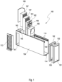
- FIG. 1 shows an integrated ventilation module 100 in a first embodiment of the invention.
- the ventilation module 100 shows a slide-in housing 104, which can be designed, for example, as an injection-molded plastic part, in particular using a plastic of fire protection class 1.
- the plug-in housing 104 has three air passages 141, 142 and 143 on its end face facing an outer wall of a building, one of which is arranged on the end face itself and the other two are arranged on the side of the end face of the plug-in housing 104.
- these air passages 141, 142, 143 allow air to be exchanged with the surroundings in different directions.
- the two openings 141 and 143 can be usefully used in conjunction with window reveals and allow installation on either the right or left side of the window.
- a horizontal installation below or above a window is also conceivable.
- the slide-in housing 104 is designed as a part that can be shortened, which means that it can be easily shortened to the desired length when inserted into a superordinate component, for example using a jigsaw, saber saw or hand-held circular saw.
- an embodiment of the slide-in housing 104 as a telescope or with a telescope channel is also conceivable.
- the air passages 141, 142 and 143 can initially be formed with inserts that can be broken out, not shown in the figure, so that the correspondingly required air passage can be broken free during or before the assembly of the ventilation module according to the invention.
- the deflection or soundproofing element 108 is arranged, which can be used in such a way that it closes two of the three air passages 141, 142, 143.
- a weather protection grille 113 can be inserted into the free air passage 141, 142 or 143 and serves on the one hand to prevent the effects of the weather on the interior of the slide-in housing 104 and also to make a further contribution to soundproofing.
- the two heat accumulators 107 which are designed as ceramic heat accumulators in the example shown, adjoin the sound insulation element 108.
- the heat accumulator 107 is followed in the interior of the slide-in housing 104 by the motor unit 106, which in the example shown here has two fans arranged one above the other and in a sandwich construction between two soundproofing elements 161 and 162 are used.
- Another soundproofing element 105 is connected to the motor unit 106; in principle, the use of several soundproofing elements is also conceivable.
- the sound insulation element 105 can be followed by an air filter, not shown in the figure, to which a panel sound insulation element 102 is connected.
- the screen sound insulation element 102 is also not absolutely necessary.
- the inner screen 101 is placed on the plug-in housing 104 and optionally the screen sound insulation element 102 .
- the inner panel 101 has three rods 103 for this purpose, which can optionally be inserted through corresponding openings in the panel sound-insulating element 102 into guide grooves 114 provided for this purpose in the slide-in housing 104 .
- the guide grooves 114 extend over a considerable distance along the slide-in housing 104, sawing off the slide-in housing 104 for the purpose of adjusting the thickness to the outer wall for fastening the inner panel 101 and the panel sound-insulating element 102 is not critical.
- the guide grooves 114 can also be inserted into the slide-in housing 104 as a separate component, in particular glued in place.
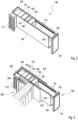
- figure 2 shows the integrated ventilation module 100 according to the invention once again in an assembled representation.
- the compact design which can be shortened in length, is clearly recognizable; in the figure 2 the reference numbers used correspond to those in FIG figure 1 already known.
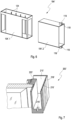
- figure 3 shows them off figure 1 known assembly group after integration into a complete window module 200, for example the above-mentioned ROKA-KOMPAKT module from Beck & Heun GmbH.
- a complete window module 200 for example the above-mentioned ROKA-KOMPAKT module from Beck & Heun GmbH.
- Such complete window modules are predominantly manufactured using an insulating material and have defined internal dimensions for the installation of practically any commercially available window.
- the complete window modules often already contain a roller shutter box (and possibly also a roller shutter already located there) as well as possible rails for roller shutters or tension cables for blinds.
- Well recognizable in figure 3 is that the ventilation module 100 integrated according to the invention is inserted into a recess 210 in the insulating material 220 of the complete window module 200 .
- the integrated ventilation module 100 can be integrated into the complete window module 200 with a certain gradient towards the outside, so that any condensate that forms can easily flow away to the outside and either evaporate or drip off on the outer shell of the building.
- the complete window module 200 is provided with stabilizing rails 216, which ensure the necessary strength in a segmented structure of the complete window module.
- FIG 5 shows a variant of the invention, in which the slide-in housing 104 'in contrast to that in the Figures 1 to 4 shown embodiment cannot be shortened by sawing off or separating off parts, but rather is formed in two parts from a base part 104'.1 and a telescopic channel 104'.2, wherein the telescopic channel 104'.2 can be pushed over the base part 104'.1.
- Both the base part 104'.1 and the telescopic channel 104'.2 can have soundproofing material, and in particular can also be made entirely of soundproofing material. Insulation layer thicknesses in the range between 10 and 20 mm are particularly advantageous.
- the two-part design with a telescopic duct allows the integrated ventilation module 100 to be adapted to wall thicknesses between 300 and 490 mm; Of course, given a suitable length of the telescopic channel 104'.2, larger wall thicknesses are also conceivable.
- Essential components of the ventilation module 100 can be accommodated in the base part 104'.1, in particular a deflection element designed as a soundproofing element, heat accumulator, motor unit, etc.
- the figure clearly shows the front end of the telescopic duct 104' facing the interior. 2 the two mounting brackets 119 provided with bores 118, which are used for mounting an inner panel.
- the inner screen can be attached to the telescope channel 104'.2 easily and without tools.
- figure 6 shows this for further clarification figure 5 known base part 104'.1 and the telescopic channel 104'.2 individually.
- the base part 104'.1 has a plurality of air passages in order to allow maximum flexibility with regard to the installation of the associated integrated ventilation module, in particular on a window. In particular, even shortly before installing the ventilation module, it can still be decided on which side of a window it should be attached.
- the base part 104'.1 is designed in such a way that both a straight air duct to the outside and a 90° air deflection can be implemented.
- both the situation that an external air outlet is arranged in the region of a window reveal and the situation that the external air outlet is arranged on the building facade pointing outwards can be taken into account.
- An advantageous length of the base part 104'.1 is in the range of 300 mm; Of course, other lengths are also conceivable, depending on structural requirements.
- Both the base part 104'.1 and the telescopic channel 104'.2 can be made of plastic in combination with an insulating material, or they can be made entirely of plastic or insulating material.
- the base part has guide ribs 124 for easy and defined insertion of the heat accumulator, the motor unit and the soundproofing elements.
- figure 7 shows a window complete module 200 ', in which one from the figures 5 and 6 known plug-in housing 104 'can be used. Essentially, it corresponds to that figure 3 known window complete module, but here in the insulating material 220 'recesses 218' for the fastening tabs 119 of the telescopic channel 104 '.2 are provided.
- figure 8 shows a built-in slide-in housing according to the Figures 5 to 7 in the insulating material 220' of a window module 200'.
- the base part 104'.1 with the telescopic channel 104'.2, two heat accumulators 107, a motor unit 106 and the inner panel 101' are clearly visible.
- the installation with an outward gradient is also clearly visible, so that any condensate that may occur can flow off to the outside.
- the gradient can also be provided in the slide-in housing, so that a gradient does not necessarily have to be provided in the complete window module.
- the lower part of the plug-in housing can be designed so that it rises towards the interior of the room, for example in the form of an inclined plane.
- the outer basic shape of the slide-in housing can remain cuboid, so that comfortable insertion into the corresponding recess and a simple configuration of the recess remain possible.
- FIG 9 shows a detailed representation of an integrated ventilation module 100' inserted into a complete window module 200' with an inner screen 101' attached on the room side with a screen sound insulation element 102'.
- the inner screen 101' is attached to the telescopic channel 104'.2 itself and not to the building wall, which considerably simplifies assembly.
- the screen soundproofing element 102′ allows on the one hand an efficient shielding of noises generated by the engine unit as well as an airtight closure by simply pressing shut by hand.
- the distance between the inner screen 101' and the wall can be chosen to be variable in the range from approximately 0 to 30 mm, but a further distance is also conceivable. For inspection purposes, such as changing the filter of the ventilation module, the inner panel 101' can be removed and reinstalled easily and without tools.
- figure 10 also shows in a detailed representation the part of a complete window module 200' according to the invention which faces the facade, with an integrated ventilation module 100'.
- the drip nose 122 arranged in the lower part of the weather protection grille, which ensures that, for example, raindrops or condensate can drip freely from the window reveal. Ideally, the distance between the drip nose 122 and the wall is about 20-50 mm.
- the weather protection grille 113' can in particular be made of aluminum or stainless steel. There are no special requirements for installing the weather protection grille 113'; in particular, easy detachability is not absolutely necessary, since the inspection of the ventilation module according to the invention takes place from the inside of the room. Aspects such as burglary security or protection against vandalism can thus also be advantageously taken into account.
- figure 11 shows in a further variant of the invention an integrated ventilation module 100" used in a window module, in which all air passages are arranged both on the room side and on the outside on the window reveal, which results in a visually pleasing image of the system according to the invention both inside and outside.
- Easily recognizable in figure 11 are the two symmetrically designed deflection elements 108, the heat accumulators 107 and the motor unit 106 adjacent to the heat accumulators 107, as well as an optional soundproofing element 105.
- the air passages not shown in the figure are covered by simple grilles 113".
- a filter 125 is arranged on the grid 113".
- a cover 123 pointing towards the inside of the room is designed to be detachable and allows easy revision of the integrated ventilation module 100" according to the invention.
- figure 12 shows a sectional view of a complete window module 200" according to the invention without an integrated ventilation module inserted, so that the simple structure of the recess 210" in the insulating material 220" can be seen.
- the recess 210" is temporarily closed with a separate filling body, for example made of an insulating material, for example for a later, subsequent installation of a ventilation module.
- a separate filling body for example made of an insulating material
- This can also take into account a later change in use of the associated room.
- this possibility is not open in the figure 12 shown embodiment limited, but can be applied generally.
- This variant of the invention allows the installation of a ventilation module to be postponed to a later date both in new construction and in the case of renovation, but at least provides the possibility of simple, inexpensive retrofitting in this case.
- the stability of the component is also ensured and simple insertion into the environment--in particular on the inside of the room, for example in connection with a layer of plaster--is made possible.
- it can be provided with non-destructively detectable markings, particularly in the area of its room-side end face, such as individual, possibly insulated electrical conductors or a network or mesh made of such conductors or a conductive foil, which can be easily detected with appropriate detectors can also be localized behind a layer of plaster.
- figure 13 shows in a separate representation in the figures 11 and 12 preferably to be used plug-in housing 104", which can be designed as a plastic part.
- FIG 14 shows a section through a window module of the embodiment according to FIGS Figures 11 to 13 in the plane of the motor unit 106.
- the arrangement of two fans one above the other is clearly visible.
- the motor unit 106 is equipped with insulating or decoupling elements 127 .
- the insulating or decoupling elements 127 allow electrical connecting lines to be laid. In the example shown, the fans are arranged in the same direction and in a neutral preferred direction.
- figure 15 shows a longitudinal section through a ventilation module 100" according to the invention installed in a window module.
- Insulation element shown can be provided for the control and for the entire cable routing recesses.
- the device operating unit can also be integrated in the complete window module or in the insulating element. This means that the entire unit can be electrically prepared at the factory, only the power supply has to be provided on site in this case.
- the installation housing described above can have a cover, for example an insulating mat, in particular on its upper side. If a sufficiently soft material is selected, the insulating mat can allow further components, such as plug connections, to be accommodated. The components can be easily pressed into the material of the cover.
Landscapes
- Engineering & Computer Science (AREA)
- Civil Engineering (AREA)
- Structural Engineering (AREA)
- Specific Sealing Or Ventilating Devices For Doors And Windows (AREA)
- Building Environments (AREA)
- Cooling Or The Like Of Electrical Apparatus (AREA)
Description
- Die Erfindung betrifft ein Fensterkomplettmodul zum Einbau in ein Gebäude.
- Im Neubau- wie auch im Renovierungsbereich haben in jüngerer Zeit modulare Lösungen für einzelne Gebäudeelemente vermehrt Verbreitung gefunden. So wird beispielsweise in der deutschen Offenlegungsschrift
DE 10 2008 048 585 A1 eine in eine vorgegebene Gebäudeöffnung einbaubare Einfassung für Fenster und/oder Türen vorgeschlagen, welche sich entlang des gesamten Umfangs der Gebäudeöffnung erstreckt und die Gebäudeöffnung vollständig umgibt, ein wärmeisolierendes Material aufweist und abgedichtet in die Gebäudeöffnung einbaubar ist. Die genannte Einfassung wird unter dem Handelsnamen "ROKA KOMPAKT" von der Beck+Heun GmbH gefertigt und vertrieben. - Parallel entstand aufgrund der immer dichter werdenden Gebäudeaußenhüllen ein gesteigerter Bedarf an Lüftungssystemen zur Zwangsbelüftung von Gebäuden. Insbesondere werden Lüftungssysteme mit Energierückgewinnungseinheiten für den Neubau sowie als Nachrüstungselemente im Gebäudebau immer wichtiger und gefragter und entsprechende Lösungen werden vermehrt am Markt angeboten und nachgefragt. Allerdings stellt sich bei der Erstausrüstung und insbesondere bei der Nachrüstung von Gebäuden oftmals das Problem fehlenden Bauraums beziehungswiese erhöhten Installationsaufwandes in Verbindung mit dem Einbau von Lüftungssystemen. Das Dokument
EP 0 132 779 A2 betrifft eine Fensterzarge aus Hohlprofilen, die ganz oder teilweise mit Dämmmaterial gefüllt sein können. DieDE 10 2012 104198 A1 beschreibt ein Rahmenlüftungsgerät, das in die Fensterlaibung, d.h. in die seitliche Mauer, die den Fensterrahmen umgibt, eingebaut wird. - Es ist daher eine Aufgabe der Erfindung, den Einbau oder die Nachrüstung von Lüftungssystemen - insbesondere in Verbindung mit den oben beschriebenen modularen Lösungen - weiter zu vereinfachen.
- Diese Aufgabe wird gelöst durch ein Fensterkomplettmodul mit den Merkmalen des Anspruchs 1. Die Unteransprüche betreffen vorteilhafte Ausführungsformen und Varianten der Erfindung.
- Ein Fensterkomplettmodul zum Einbau in ein Gebäude, wobei das Fensterkomplettmodul unter Verwendung eines Dämmmaterials gefertigt ist, weist im Dämmmaterial eine Ausnehmung auf, in welcher ein integriertes Lüftungsmodul mindestens teilweise anordenbar ist. Dadurch wird vermieden, dass für Lüftungsmodule zusätzlich Platz im Mauerwerk geschaffen werden muss. Das umgebende Dämmmaterial sorgt darüber hinaus auch für eine verbesserte Schalldämmung des Lüftungsmoduls. Ferner schafft die erfindungsgemäße Lösung die Möglichkeit, das Lüftungsmodul gegebenenfalls inklusive einer Steuer- und Bedieneinheit vormontiert bereitzustellen. Hierdurch entfallen bei der Montage im Neubau oder bei der Sanierung die nach dem Stand der Technik erforderlichen gewerkübergreifenden Arbeiten, wodurch auch Probleme, die sich aus Fragen der Gewährleistung ergeben könnten, vermieden werden. Es versteht sich von selbst, dass durch die erfindungsgemäße Lösung auch das Risiko von Montagefehlern verringert wird und insgesamt eine schnellere Montage eines Lüftungssystems bzw. dessen Nachrüstung möglich wird.
- In einer vorteilhaften Ausführungsform des erfindungsgemäßen Fensterkomplettmoduls weist die Ausnehmung ein Gefälle zur Gebäudeaußenseite hin auf. So kann das in einem Lüftungsmodul eventuell anfallende Kondenswasser optimal abfließen.
- Dabei kann das Gefälle insbesondere zwischen 1% und 5% betragen.
- Das Fensterkomplettmodul weist weiterhin erfindungsgemäß ein Lüftungsmodul auf, welches ein Einschubgehäuse sowie eine Motoreinheit und mindestens einen Wärmespeicher aufweist. Durch die integrierte Ausführung des Lüftungsmoduls wird ein einfaches Einsetzen des Moduls in die dafür vorgesehene Ausnehmung im Dämmmaterial des Fensterkomplettmoduls ermöglicht.
- Von Vorteil ist es, wenn das Einschubgehäuse mit einem Luftdurchlass versehen ist, welches derart angeordnet ist, dass der Luftdurchlass zu einer Fensterlaibung des Fensterkomplettmoduls hin ausgerichtet ist. So wird die optische Beeinträchtigung der Fassade sowie der Innenwand verringert. Weiterhin wird die Gefahr eines Luftzugs von außen nach innen vermindert, da die Geschwindigkeit der eintretenden Luft durch die Umlenkung verringert wird; ferner ergeben sich schalltechnische Vorteile.
- Ein in dem Fensterkomplettmodul integriertes Lüftungsmodul weist erfindungsgemäß ein Einschubgehäuse sowie mindestens eine in dem Einschubgehäuse angeordnete Motoreinheit und mindestens einen ebenfalls in dem Einschubgehäuse angeordneten Wärmespeicher auf.
- Das Einschubgehäuse eines integrierten Lüftungsmoduls ist in vorteilhafter Weise als kürzbares Teil ausgeführt. So kann das Einschubgehäuse an jede beliebige Stelle eines Gebäudes mit nahezu jeder beliebigen Stärke eingebaut werden. Beim Einsetzen in ein übergeordnetes Bauelement kann es auf einfache Weise, beispielsweise mittels einer Stich-, Säbel- oder Handkreissäge, auf die gewünschte Länge gekürzt werden.
- Weiterhin denkbar ist, dass das Einschubgehäuse des integrierten Lüftungsmoduls als Teleskop bzw. mit einem Teleskopkanal ausgeführt ist. So ist die Anpassung des integrierten Lüftungsmoduls an die Breite der gewünschten Einbaustelle durch bloßes Verschieben der Teleskopelemente gegeneinander durchführbar.
- Ein erfindungsgemäßes integriertes Lüftungsmodul weist bevorzugt im Bereich mindestens einer seiner Stirnseiten mehrere Luftdurchlässe auf, von welchen mindestens einer durch ein Umlenk- bzw. Schalldämmelement verschlossen ist. So kann individuell entschieden werden, an welcher Seite ein Luftdurchlass offen bleibt.
- Darüber hinaus ist es von Vorteil, wenn das Einschubgehäuse des integrierten Lüftungsmoduls auf seiner der Innenseite eines Gebäudes zugewandten Seite eine Innenblende mit mindestens einer Stange aufweist, welche in eine Führungsnut im Einschubgehäuse eingeführt ist. Dies gewährleistet eine einfache Montage und Demontage der Innenblende sowie eventuelle Reinigung der einzelnen Bestandteile des Lüftungsmoduls.
- Nachfolgend werden Varianten der Erfindung anhand der Zeichnung näher erläutert.
Es zeigt: - Figur 1:
- eine schematische Darstellung einer ersten Ausführungsform eines integrierten Lüftungsmoduls,
- Figur 2:
- eine zusammengesetzte Darstellung des integrierten Lüftungsmoduls,
- Figur 3:
- eine schematische Darstellung des in ein Fensterkomplettmodul integrierten Lüftungsmoduls,
- Figur 4:
- eine schematische Darstellung einer Variante der Erfindung integriert in ein Dämmelement,
- Figur 5:
- eine schematische Darstellung eines Einschubgehäuses,
- Figur 6:
- eine schematische Darstellung eines Basisteils und eines Teleskopkanals eines Einschubgehäuses,
- Figur 7:
- eine schematische Darstellung eines Fensterkomplettmoduls,
- Figur 8:
- eine schematische Darstellung eines eingebauten Einschubgehäuses im Längsschnitt,
- Figur 9:
- eine schematische Detaildarstellung eines erfindungsgemäßen Lüftungsmoduls integriert in ein Fensterkomplettmodul,
- Figur 10:
- eine weitere Detaildarstellung eines erfindungsgemäßen Lüftungsmoduls integriert in ein Fensterkomplettmodul,
- Figur 11:
- eine schematische Darstellung einer weiteren Variante eines in ein Fensterkomplettmodul eingesetzten integrierten Lüftungsmoduls,
- Figur 12:
- eine schematische Schnittdarstellung eines Fensterkomplettmoduls ohne integriertes Lüftungsmodul,
- Figur 13:
- eine schematische Darstellung einer Variante eines Einschubgehäuses,
- Figur 14:
- eine schematische Schnittdarstellung durch ein Fensterkomplettmodul mit integriertem Lüftungsmodul; und
- Figur 15:
- eine schematische Darstellung eines Längsschnitts durch ein Fensterkomplettmodul mit integriertem Lüftungsmodul.
-
Figur 1 zeigt in einer ersten Ausführungsform der Erfindung ein integriertes Lüftungsmodul 100. Dabei zeigt das Lüftungsmodul 100 ein Einschubgehäuse 104, welches beispielsweise als spritzgegossenes Kunststoffteil insbesondere unter Verwendung eines Kunststoffes der Brandschutzklasse 1 ausgeführt sein kann. Das Einschubgehäuse 104 weist an seiner einer Außenwand eines Gebäudes zugewandten Stirnseite drei Luftdurchlässe 141, 142 und 143 auf, von denen einer an der Stirnseite selbst und die beiden anderen seitlich der Stirnseite des Einschubgehäuses 104 angeordnet sind. Diese Luftdurchlässe 141, 142, 143 ermöglichen es je nach Einbausituation Luft mit der Umgebung in verschiedene Richtungen auszutauschen. Insbesondere können die beiden Öffnungen 141 und 143 sinnvoll in Verbindung mit Fensterlaibungen verwendet werden und gestatten den Einbau entweder auf der rechten oder der linken Seite des Fensters. Selbstverständlich ist auch ein liegender Einbau unterhalb oder oberhalb eines Fensters denkbar. Das Einschubgehäuse 104 ist im gezeigten Beispiel als kürzbares Teil ausgeführt, das heißt, dass es beim Einsetzen in ein übergeordnetes Bauelement auf einfache Weise, beispielsweise mittels einer Stich-, Säbel- oder Handkreissäge, auf die gewünschte Länge gekürzt werden kann. Selbstverständlich ist auch eine Ausführung des Einschubgehäuses 104 als Teleskop bzw. mit einem Teleskopkanal denkbar. Die Luftdurchlässe 141, 142 und 143 können zunächst mit in der Figur nicht dargestellten herausbrechbaren Einsätzen ausgebildet sein, so dass bei bzw. vor der Montage des erfindungsgemäßen Lüftungsmoduls der entsprechend benötigte Luftdurchlass freigebrochen werden kann. Unmittelbar im Bereich der Luftdurchlässe 141, 142 und 143 ist das Umlenk- bzw. Schalldämmelement 108 angeordnet, welches so eingesetzt werden kann, dass es zwei der drei Luftdurchlässe 141, 142, 143 schließt. Damit besteht alternativ zu der vorstehend beschriebenen Möglichkeit der herausbrechbaren Einsätze auch die Möglichkeit, alle drei Öffnungen 141, 142, 143 ohne Einsätze vorzusehen und lediglich mittels des Schalldämmelements 108 je nach Einbausituation geeignet abzudecken bzw. ein für die jeweilige Einbausituation geeignetes Schalldämmelement zu verwenden. Ein Wetterschutzgitter 113 kann in den freien Luftdurchlass 141, 142 oder 143 eingesetzt werden und dient einerseits dazu, das Einwirken von Witterungseinflüssen in das Innere des Einschubgehäuses 104 zu unterbinden und darüber hinaus einen weiteren Beitrag zum Schallschutz zu leisten. Zusätzlich oder alternativ ist auch die Montage einer Wetterschutzhaube mit optionaler zusätzlicher Schalldämmung möglich. - Im Innenbereich des Einschubgehäuses 104 schließen sich an das Schalldämmelement 108 die beiden Wärmespeicher 107 an, die im gezeigten Beispiel als Keramikwärmespeicher ausgeführt sind. Auch alternative Materialien/Ausführungsformen der Wärmespeicher 107, beispielsweise unter Verwendung von Aluminium, sind denkbar.
- Auf die Wärmespeicher 107 folgt im Inneren des Einschubgehäuses 104 die Motoreneinheit 106, welche im vorliegend gezeigten Beispiel zwei übereinander angeordnete Lüfter aufweist und in einer Sandwichbauweise zwischen zwei Schalldämmelementen 161 und 162 eingesetzt ist. An die Motoreneinheit 106 schließt sich ein weiteres Schalldämmelement 105 an; grundsätzlich ist auch die Verwendung mehrerer Schalldämmelemente denkbar. Im weiteren Verlauf kann auf das Schalldämmelement 105 ein in der Figur nicht dargestellter Luftfilter folgen, an welchen sich ein Blendenschalldämmelement 102 anschließt. Das Blendenschalldämmelement 102 ist ebenfalls nicht zwingend erforderlich. Schließlich ist an der Rauminnenseite auf das Einschubgehäuse 104 und gegebenenfalls das Blendenschalldämmelement 102 die Innenblende 101 aufgesetzt. Die Innenblende 101 zeigt dazu drei Stangen 103, welche gegebenenfalls durch entsprechende Öffnungen im Blendenschalldämmelement 102 in hierfür vorgesehene Führungsnuten 114 im Einschubgehäuse 104 eingesetzt werden können. Auf diese Weise wird eine werkzeug- und dübellose Montage der Innenblende 101 und des Blendenschalldämmelements 102 ermöglicht. Da sich die Führungsnuten 114 über einen erheblichen Weg längs des Einschubgehäuses 104 erstrecken, ist auch ein Absägen des Einschubgehäuses 104 zum Zweck der Dickenanpassung an die Außenwand für die Befestigung der Innenblende 101 und des Blendenschalldämmelements 102 unkritisch. Alternativ können die Führungsnuten 114 auch als separates Bauteil in das Einschubgehäuse 104 eingesetzt, insbesondere eingeklebt sein.
-
Figur 2 zeigt noch einmal in einer zusammengesetzten Darstellung das erfindungsgemäße integrierte Lüftungsmodul 100. Gut erkennbar wird die kompakte, in der Länge kürzbare Bauform; die inFigur 2 verwendeten Bezugsziffern entsprechen den ausFigur 1 bereits bekannten. -
Figur 3 zeigt die ausFigur 1 bekannte Baugruppe nach der Integration in ein Fensterkomplettmodul 200, beispielsweise das oben bereits erwähnte Modul ROKA-KOMPAKT von der Beck & Heun GmbH. Derartige Fensterkomplettmodule sind überwiegend unter Verwendung eines Dämmmaterials gefertigt und zeigen definierte Innenabmessungen zum Einbau praktisch beliebiger handelsüblicher Fenster. Die Fensterkomplettmodule enthalten dabei oftmals bereits einen Rollladenkasten (und gegebenenfalls auch einen dort bereits befindlichen Rollladen) sowie eventuelle Schienen für Rollläden bzw. Spannseile für Jalousien. Gut erkennbar inFigur 3 wird, dass das erfindungsgemäß integrierte Lüftungsmodul 100 in eine Ausnehmung 210 im Dämmmaterial 220 des Fensterkomplettmoduls 200 eingesetzt ist. Insbesondere kann das erfindungsgemäße integrierte Lüftungsmodul 100 mit einem gewissen Gefälle nach außen hin in das Fensterkomplettmodul 200 integriert werden, so dass sich eventuell bildendes Kondensat auf einfache Weise nach außen wegströmen kann und an der Gebäudeaußenhülle entweder verdunstet oder abtropft. Ferner ist aus derFigur 3 erkennbar, dass das Fensterkomplettmodul 200 mit Stabilisierungsschienen 216 versehen ist, welche bei einem segmentierten Aufbau des Fensterkomplettmoduls die notwendige Festigkeit gewährleisten. -
Figur 4 zeigt eine weitere Variante der Erfindung, bei welcher das bereits bekannte integrierte Lüftungsmodul 100 in einem Dämmelement 300 unabhängig von einem Fensterkomplettmodul integriert ist. Auch hier werden die aus den vorstehenden Figuren bereits bekannten Bezugsziffern verwendet. Dabei kann in dem Dämmelement prinzipiell jedes der vorliegend gezeigten integrierten Lüftungsmodule verwendet werden. Derartige Dämmelemente können in einer Vielzahl von Anwendungsfällen zum Einsatz kommen. Insbesondere sind folgende Fälle denkbar: - Nachträglicher Einbau in Bestandsgebäuden, bei welchen die Fenster nicht oder erst zu einem späteren Zeitpunkt getauscht werden sollen
- Nachträglicher Einbau in Bestandsgebäude, bei denen die bestehende Fensteröffnung im Mauerwerk nicht verkleinert werden soll
- Einbau in Gebäude unabhängig bzw. beabstandet von Fensteröffnungen an einen beliebigen Ort in der Außenwand.
- In den nachfolgend beschriebenen Figuren wurden korrespondierende Bauteile verschiedener Ausführungsformen mit gestrichenen Bezugsziffern versehen. Dabei werden in einer vorangegangenen Ausführungsform bereits beschriebene Elemente in den nachfolgenden Ausführungsformen nicht mehr gesondert diskutiert.
-
Figur 5 zeigt eine Variante der Erfindung, bei welcher das Einschubgehäuse 104' im Unterschied zu der in denFiguren 1 bis 4 gezeigten Ausführungsform nicht durch Absägen oder Abtrennen von Teilen kürzbar, sondern vielmehr zweiteilig aus einem Basisteil 104'.1 und einem Teleskopkanal 104'.2 ausgebildet ist, wobei der Teleskopkanal 104'.2 über das Basisteil 104'.1 geschoben werden kann. Sowohl Basisteil 104'.1 als auch der Teleskopkanal 104'.2 können Schalldämmmaterial aufweisen, insbesondere auch vollständig aus Schalldämmmaterial gebildet sein. Besonders vorteilhaft sind dabei Dämmschichtdicken im Bereich zwischen 10 bis 20 mm. Die zweiteilige Ausführung mit Teleskopkanal erlaubt insbesondere eine Anpassung des integrierten Lüftungsmoduls 100 an Wandstärken zwischen 300 und 490 mm; selbstverständlich sind bei geeigneter Länge des Teleskopkanals 104'.2 auch größere Wandstärken denkbar. Wesentliche Komponenten des Lüftungsmoduls 100 können dabei in dem Basisteil 104'.1 untergebracht sein, insbesondere ein als Schalldämmelement ausgebildetes Umlenkelement, Wärmespeicher, Motoreneinheit, u. ä. In der Figur gut erkennbar sind am stirnseitigen, dem Innenraum zugewandten Ende des Teleskopkanals 104'.2 die beiden mit Bohrungen 118 versehenen Befestigungslaschen 119, welche der Befestigung einer Innenblende dienen. Die Innenblende kann dabei einfach und werkzeuglos am Teleskopkanal 104'.2 angebracht sein. -
Figur 6 zeigt zur weiteren Verdeutlichung das ausFigur 5 bekannte Basisteil 104'.1 und den Teleskopkanal 104'.2 einzeln. Gut erkennbar wird dabei, dass das Basisteil 104'.1 eine Mehrzahl von Luftdurchlässen aufweist, um eine maximale Flexibilität im Hinblick auf die Montage des zugehörigen integrierten Lüftungsmoduls insbesondere an einem Fenster zu ermöglichen. Insbesondere kann selbst kurz vor Einbau des Lüftungsmoduls noch entschieden werden, an welcher Seite eines Fensters es angebracht werden soll. Im gezeigten Beispiel ist das Basisteil 104'.1 derart ausgebildet, dass sowohl eine gerade Luftführung nach außen als auch eine 90° Luftumlenkung realisiert werden können. Mit anderen Worten kann sowohl der Situation Rechnung getragen werden, dass ein äußerer Luftdurchlass im Bereich einer Fensterlaibung angeordnet ist als auch der Situation, dass der äußere Luftdurchlass an der Gebäudefassade nach außen weisend angeordnet ist. Eine vorteilhafte Länge des Basisteils 104'.1 liegt im Bereich von 300 mm; selbstverständlich sind auch andere Längen je nach baulicher Anforderung denkbar. Sowohl Basisteil 104'.1 als auch Teleskopkanal 104'.2 können aus Kunststoff in Verbund mit einem Dämmmaterial wie auch vollständig aus Kunststoff bzw. Dämmmaterial gebildet sein. Weiterhin weist das Basisteil Führungsrippen 124 zum einfachen und definierten Einsetzen der Wärmespeicher, der Motoreneinheit und der Schalldämmelemente auf. -
Figur 7 zeigt ein Fensterkomplettmodul 200', in welches ein aus denFiguren 5 und6 bekanntes Einschubgehäuse 104' eingesetzt werden kann. Im Wesentlichen entspricht es dem ausFigur 3 bekannten Fensterkomplettmodul, wobei jedoch hier im Dämmmaterial 220' Ausnehmungen 218' für die Befestigungslaschen 119 des Teleskopkanals 104'.2 vorgesehen sind. -
Figur 8 zeigt ein eingebautes Einschubgehäuse nach denFiguren 5 bis 7 im Dämmmaterial 220' eines Fenstermoduls 200'. Gut erkennbar sind das Basisteil 104'.1 mit dem Teleskopkanal 104'.2, zwei Wärmespeicher 107, eine Motoreinheit 106 sowie die Innenblende 101'. Ebenfalls gut erkennbar ist der Einbau mit Gefälle nach außen, so dass evtl. anfallendes Kondensat nach außen abfließen kann. - Das Gefälle kann alternativ auch im Einschubgehäuse vorgesehen sein, so dass im Fensterkomplettmodul nicht zwingend ein Gefälle vorzusehen ist. Dabei kann insbesondere der untere Teil des Einschubgehäuses in seinem Innenbereich zum Rauminneren hin ansteigend ausgebildet sein, bspw. in Form einer schiefen Ebene. Die äußere Grundform des Einschubgehäuses kann dabei quaderförmig verbleiben, so dass nach wie vor ein komfortables Einführen in die entsprechende Ausnehmung und eine einfache Gestaltung der Ausnehmung möglich bleibt.
-
Figur 9 zeigt in einer Detaildarstellung ein in ein Fensterkomplettmodul 200' eingesetztes integriertes Lüftungsmodul 100' mit einer raumseitig angebrachten Innenblende 101' mit einem Blendenschalldämmelement 102'. Die Innenblende 101' wird dabei am Teleskopkanal 104'.2 selbst und nicht an der Gebäudewand angebracht, was die Montage erheblich vereinfacht. Das Blendenschalldämmelement 102' erlaubt einerseits eine effiziente Abschirmung von seitens der Motoreneinheit erzeugten Geräuschen wie auch eine luftdichte Verschließung durch einfaches Zudrücken von Hand. Dabei kann der Abstand der Innenblende 101' von der Wand variabel im Bereich von ca. 0 bis 30 mm gewählt werden, auch ein weiterer Abstand ist denkbar. Zu Revisionszwecken, wie beispielsweise zum Filterwechsel des Lüftungsmoduls, kann die Innenblende 101' einfach und werkzeuglos entfernt und wieder montiert werden. -
Figur 10 zeigt ebenfalls in einer Detaildarstellung den der Fassade zugewandten Teil eines erfindungsgemäßen Fensterkomplettmoduls 200' mit integriertem Lüftungsmodul 100'. Gut erkennbar ist dabei das Wetterschutzgitter 113' mit starren, nicht verstellbaren Lamellen, welche nach innen angeordnet sind, so dass sich keine überstehenden Elemente ergeben. Auch verstellbare Lamellen oder andere Formen von Lamellen wie beispielsweise eine waagerechte oder senkrechte Anordnung der Lamellen sind denkbar. Ebenfalls gut erkennbar inFigur 10 ist die im unteren Teil des Wetterschutzgitters angeordnete Abtropfnase 122, welche gewährleistet, dass beispielsweise Regentropfen oder anfallendes Kondensat frei von der Fensterlaibung abtropfen kann. Idealerweise beträgt der Abstand der Abtropfnase 122 zur Wand ca. 20 - 50 mm. Das Wetterschutzgitter 113' kann insbesondere aus Aluminium oder Edelstahl gebildet sein. An die Montage des Wetterschutzgitters 113' sind keine besondere Anforderungen zu stellen; insbesondere ist auch eine leichte Lösbarkeit nicht zwingend erforderlich, da die Revision des erfindungsgemäßen Lüftungsmoduls von der Rauminnenseite her erfolgt. Somit kann auch Aspekten wie beispielsweise Einbruchsicherheit oder Schutz gegen Vandalismus vorteilhaft Rechnung getragen werden. -
Figur 11 zeigt in einer weiteren Variante der Erfindung ein in ein Fenstermodul eingesetztes integriertes Lüftungsmodul 100", bei welchem sämtliche Luftdurchlässe sowohl raumseitig wie auch außenseitig an der Fensterlaibung angeordnet sind, wodurch sich innen wie außen ein optisch gefälliges Bild des erfindungsgemäßen Systems ergibt. Gut erkennbar inFigur 11 sind die beiden symmetrisch ausgebildeten Umlenkelemente 108, die Wärmespeicher 107 und die den Wärmespeichern 107 benachbarte Motoreneinheit 106 sowie ein optionales Schalldämmelement 105. Im Innen- wie im Außenbereich sind die in der Figur nicht bezeichneten Luftdurchlässe durch einfache Gitter 113" abgedeckt. Im Bereich des raumseitigen Gitters 113" ist ein Filter 125 angeordnet. Eine zur Rauminnenseite hin weisende Abdeckung 123 ist lösbar ausgebildet und ermöglicht eine einfache Revision des erfindungsgemäßen integrierten Lüftungsmoduls 100". -
Figur 12 zeigt in einer Schnittdarstellung ein erfindungsgemäßes Fensterkomplettmodul 200" ohne eingesetztes integriertes Lüftungsmodul, so dass der einfache Aufbau der Ausnehmung 210" im Dämmmaterial 220" erkennbar wird. - Insgesamt ist denkbar, dass die Ausnehmung 210" mit einem separaten Füllkörper beispielsweise aus einem Dämmmaterial vorübergehend verschlossen wird, beispielweise für einen späteren, nachträglichen Einbau eines Lüftungsmoduls. Hierdurch kann auch einer späteren Nutzungsänderung des zugehörigen Raumes Rechnung getragen werden. Selbstverständlich ist diese Möglichkeit nicht auf die in
Figur 12 gezeigte Ausführungsform beschränkt, sondern kann allgemein zur Anwendung kommen. Diese Variante der Erfindung erlaubt es sowohl im Neubaubereich wie auch im Fall einer Sanierung, den Einbau eines Lüftungsmoduls zunächst auf einen späteren Zeitpunkt zu verschieben, jedoch für diesen Fall zumindest die Möglichkeit der einfachen, kostengünstigen Nachrüstung zu schaffen. Dadurch, dass in der Ausnehmung ein separater Füllkörper vorhanden ist, wird darüber hinaus die Stabilität des Bauelementes sichergestellt und ein einfaches Einfügen in die Umgebung - insbesondere auf der Rauminnenseite, bspw. in Verbindung mit einer Putzschicht - ermöglicht. Zur besseren späteren Auffindbarkeit des Füllkörpers kann dieser insbesondere im Bereich seiner raumseitigen Stirnseite mit zerstörungsfrei auffindbaren Markierungen versehen sein, wie beispielsweise einzelnen, gegebenenfalls isolierten elektrischen Leitern oder einem Netz bzw. Geflecht aus derartigen Leitern oder auch einer leitenden Folie, welche mit entsprechenden Detektoren ohne Schwierigkeiten auch hinter einer Putzschicht lokalisiert werden können. -
Figur 13 zeigt in einer gesonderten Darstellung das in denFiguren 11 und12 vorzugsweise zu verwendende Einschubgehäuse 104", welches als Kunststoffteil ausgebildet sein kann. -
Figur 14 zeigt einen Schnitt durch ein Fenstermodul der Ausführungsform nach denFiguren 11 bis 13 in der Ebene der Motoreneinheit 106. Gut erkennbar wird die Anordnung zweier Lüfter übereinander. Die Motoreneinheit 106 ist mit Dämm- bzw. Entkoppelelementen 127 ausgestattet. Die Dämm- bzw. Entkoppelelemente 127 erlauben das Verlegen elektrischer Verbindungsleitungen. Die Lüfter sind im gezeigten Beispiel richtungsgleich und vorzugsrichtungsneutral angeordnet. -
Figur 15 zeigt einen Längsschnitt durch ein in ein Fenstermodul eingebautes erfindungsgemäßes Lüftungsmodul 100". Gut erkennbar sind die Umlenkelemente 108 sowie die Wärmespeicher 107 wie auch die Motoreneinheit 106 und das Schalldämmelement 105. - Es versteht sich von selbst, dass der Fachmann die anhand einer der vorstehend beschriebenen Ausführungsformen erläuterten Detaillösungen ohne Weiteres auf die übrigen gezeigten Ausführungsformen - soweit technisch sinnvoll - übertragen kann.
- Sowohl im Fensterkomplettmodul als auch in dem in
Figur 4 gezeigten Dämmelement können für die Steuerung sowie für die gesamte Kabelführung Ausnehmungen vorgesehen sein. Zudem kann auch die Gerätebedieneinheit im Fensterkomplettmodul oder im Dämmelement integriert werden. Dadurch kann die gesamte Einheit ab Werk elektrisch vorbereitet werden, lediglich die Stromzufuhr hat in diesem Fall bauseits zu erfolgen. - Ferner kann das vorstehend beschriebene Einbaugehäuse insbesondere an seiner Oberseite eine Abdeckung, beispielsweise eine Dämmmatte, aufweisen. Dabei kann es die Dämmmatte bei der Wahl eines hinreichend weichen Materials erlauben, weitere Komponenten, wie bspw. Steckverbindungen, aufzunehmen. Die Komponenten können dabei auf einfache Weise in das Material der Abdeckung eingedrückt werden.
Claims (11)
- Fensterkomplettmodul (200, 200', 200") zum Einbau in ein Gebäude, wobei das Fensterkomplettmodul (200, 200', 200") unter Verwendung eines Dämmmaterials (220, 220', 220") gefertigt ist und in eine vorgegebene Gebäudeöffnung derart einbaubar ist, dass es die Gebäudeöffnung vollständig umgibt, wobei das Fensterkomplettmodul eine Öffnung mit definierten Innenabmessungen zum Einbau handelsüblicher Fenster aufweist, wobei das Dämmmaterial (220, 220', 220") eine Ausnehmung (210, 210',210") aufweist, wobei ein integriertes Lüftungsmodul (100,100', 100") zumindest teilweise in die Ausnehmung integriert ist, dadurch gekennzeichnet, dass das integrierte Lüftungsmodul ein Einschubgehäuse (104, 104',104") sowie eine in dem Einschubgehäuse (104, 104', 104") angeordnete Motoreinheit (106) und mindestens einen ebenfalls in dem Einschubgehäuse (104, 104', 104") angeordneten Wärmespeicher (107) aufweist.
- Fensterkomplettmodul nach Anspruch 1, dadurch gekennzeichnet, dass das Fensterkomplettmodul einen Rollladenkasten aufweist.
- Fensterkomplettmodul nach Anspruch 1 oder 2, dadurch gekennzeichnet, dass das Lüftungsmodul eine Steuer- und Bedieneinheit aufweist.
- Fensterkomplettmodul, nach einem der Ansprüche 1 bis 3, dadurch gekennzeichnet, dass das Lüftungsmodul ein Einschubgehäuse aufweist, welches mit einem Luftdurchlass versehen ist, welcher derart angeordnet ist, dass der Luftdurchlass zu einer Fensterlaibung des Fensterkomplettmoduls hin ausgerichtet ist.
- Fensterkomplettmodul (200, 200', 200") nach einem der Ansprüche 1 bis 4, dadurch gekennzeichnet, dass die Ausnehmung (210, 210', 210") ein Gefälle zur Gebäudeaußenseite hin aufweist.
- Fensterkomplettmodul (200, 200', 200") nach Anspruch 5, dadurch gekennzeichnet, dass das Gefälle zwischen 1% und 5% beträgt.
- Fensterkomplettmodul (200, 200', 200") nach einem der vorangehenden Ansprüche 1-6, dadurch gekennzeichnet, dass die Ausnehmung (210, 210', 210") mit einem separaten Füllkörper, insbesondere aus einem Dämmmaterial, verschlossen ist.
- Fensterkomplettmodul (200, 200', 200") nach Anspruch 7, wobei das Einschubgehäuse (104, 104', 104") als kürzbares Teil ausgeführt ist.
- Fensterkomplettmodul (200, 200', 200") nach Anspruch 7, wobei das Einschubgehäuse (104, 104', 104") als Teleskop bzw. mit einem Teleskopkanal ausgeführt ist.
- Fensterkomplettmodul (200, 200', 200") nach einem der Ansprüche 7 bis 9, wobei das Lüftungsmodul (100, 100', 100") im Bereich mindestens einer seiner Stirnseiten mehrere Luftdurchlässe (141,142, 143) aufweist, von welchen mindestens einer durch ein Umlenk- bzw. Schalldämmelement (108) verschlossen ist.
- Fensterkomplettmodul (200, 200', 200") nach einem der Ansprüche 7-10, wobei das Einschubgehäuse (104, 104', 104") auf seiner der Innenseite eines Gebäudes zugewandten Seite eine Innenblende (101) mit mindestens einer Stange (103) aufweist, welche in eine Führungsnut (114) im Einschubgehäuse (104, 104',104") eingeführt ist.
Applications Claiming Priority (1)
| Application Number | Priority Date | Filing Date | Title |
|---|---|---|---|
| DE102014101544.4A DE102014101544A1 (de) | 2014-02-07 | 2014-02-07 | Fensterkomplettmodul, integriertes Lüftungsmodul sowie Dämmelement |
Publications (4)
| Publication Number | Publication Date |
|---|---|
| EP2905412A2 EP2905412A2 (de) | 2015-08-12 |
| EP2905412A3 EP2905412A3 (de) | 2015-11-04 |
| EP2905412B1 EP2905412B1 (de) | 2019-01-09 |
| EP2905412B2 true EP2905412B2 (de) | 2023-05-31 |
Family
ID=52595043
Family Applications (1)
| Application Number | Title | Priority Date | Filing Date |
|---|---|---|---|
| EP15153568.9A Active EP2905412B2 (de) | 2014-02-07 | 2015-02-03 | Fensterkomplettmodul, integriertes Lüftungsmodul sowie Dämmelement |
Country Status (2)
| Country | Link |
|---|---|
| EP (1) | EP2905412B2 (de) |
| DE (1) | DE102014101544A1 (de) |
Families Citing this family (6)
| Publication number | Priority date | Publication date | Assignee | Title |
|---|---|---|---|---|
| DE202016101081U1 (de) | 2016-03-01 | 2017-06-02 | Beck + Heun Gmbh | Lüftungsvorrichtung für ein Gebäude |
| DE102016103950B4 (de) | 2016-03-04 | 2022-05-19 | Beck+Heun Gmbh | Anordnung zur Be- und Entlüftung von Räumen im Bereich eines Fensters |
| DE102017124111A1 (de) * | 2016-10-25 | 2018-04-26 | Meltem Wärmerückgewinnung GmbH & Co. KG | Montagevorrichtung zur Montage einer Lüftungsvorrichtung |
| DE102019110282A1 (de) * | 2019-04-18 | 2020-10-22 | Vestaxx Gmbh | Fassadenelement |
| DE102020106629A1 (de) | 2020-03-11 | 2021-09-16 | Stiebel Eltron Gmbh & Co. Kg | Lüftungskanalmodul, Lüftungssystem, Gebäudewand |
| AT524146A1 (de) * | 2020-09-04 | 2022-03-15 | Kalch Reinhard | Lüftungsgerät mit Fassadenanschluss |
Citations (6)
| Publication number | Priority date | Publication date | Assignee | Title |
|---|---|---|---|---|
| DE8701661U1 (de) † | 1987-02-04 | 1987-06-25 | Kiparski, Heinz | Ab- und Zuluftmauerkasten |
| EP1486637A2 (de) † | 2003-06-12 | 2004-12-15 | Lidartech Co., Ltd. | Fenster mit Lüftungsvorrichtung |
| DE10341098A1 (de) † | 2003-09-05 | 2005-06-30 | Erwin Müller GmbH | Lüftungseinheit zur Integration in ein Rahmenprofil |
| EP1840478A1 (de) † | 2006-03-29 | 2007-10-03 | Fensterfabrik Albisrieden Ag | Fensterbereich |
| JP2011242067A (ja) † | 2010-05-19 | 2011-12-01 | Panasonic Corp | 通気パイプユニット |
| DE102012200571A1 (de) † | 2011-01-14 | 2012-07-19 | Profine Gmbh | Montagegehäuse für ein Lüftungsmodul und Verfahren zur Montage eines Lüftungsmoduls |
Family Cites Families (7)
| Publication number | Priority date | Publication date | Assignee | Title |
|---|---|---|---|---|
| EP0132779A3 (de) * | 1983-07-23 | 1985-10-23 | Hans Schlitzberger | Fensterzarge |
| NL186462C (nl) * | 1987-02-10 | 1990-12-03 | Compri Aluminium | Ventilatieschuif. |
| DE102004001313A1 (de) * | 2003-01-10 | 2004-07-22 | Lüftomatic GmbH Lüftungs- und Klimatechnik | Lüftungsvorrichtung |
| DE102004062053A1 (de) * | 2004-12-23 | 2006-07-13 | Hydro Building Systems Gmbh | Elementmodul zum Einbau in Fassaden und dergleichen |
| DE102008048585A1 (de) | 2008-09-23 | 2010-03-25 | Beck, Bernd | Einfassung für Gebäudeöffnungen |
| DE102009057355B4 (de) * | 2009-12-07 | 2025-01-02 | Ventomaxx Gmbh | Lüftungseinrichtung zum Zuführen und/oder Abführen von Luft |
| DE102012104198A1 (de) * | 2012-05-14 | 2013-11-14 | Hautau Gmbh | Rahmenlüftungsgerät, Fensteranordnung und eingebautes Fenster mit Lüftungsgerät zum Lüften und zum Erhalt der regulären Verglasungsgröße und auch Rahmenmaße |
-
2014
- 2014-02-07 DE DE102014101544.4A patent/DE102014101544A1/de active Pending
-
2015
- 2015-02-03 EP EP15153568.9A patent/EP2905412B2/de active Active
Patent Citations (6)
| Publication number | Priority date | Publication date | Assignee | Title |
|---|---|---|---|---|
| DE8701661U1 (de) † | 1987-02-04 | 1987-06-25 | Kiparski, Heinz | Ab- und Zuluftmauerkasten |
| EP1486637A2 (de) † | 2003-06-12 | 2004-12-15 | Lidartech Co., Ltd. | Fenster mit Lüftungsvorrichtung |
| DE10341098A1 (de) † | 2003-09-05 | 2005-06-30 | Erwin Müller GmbH | Lüftungseinheit zur Integration in ein Rahmenprofil |
| EP1840478A1 (de) † | 2006-03-29 | 2007-10-03 | Fensterfabrik Albisrieden Ag | Fensterbereich |
| JP2011242067A (ja) † | 2010-05-19 | 2011-12-01 | Panasonic Corp | 通気パイプユニット |
| DE102012200571A1 (de) † | 2011-01-14 | 2012-07-19 | Profine Gmbh | Montagegehäuse für ein Lüftungsmodul und Verfahren zur Montage eines Lüftungsmoduls |
Also Published As
| Publication number | Publication date |
|---|---|
| DE102014101544A1 (de) | 2015-08-13 |
| EP2905412B1 (de) | 2019-01-09 |
| EP2905412A2 (de) | 2015-08-12 |
| EP2905412A3 (de) | 2015-11-04 |
Similar Documents
| Publication | Publication Date | Title |
|---|---|---|
| EP2905412B2 (de) | Fensterkomplettmodul, integriertes Lüftungsmodul sowie Dämmelement | |
| DE102015113453A1 (de) | Einbausatz für einen französischen Balkon | |
| DE102010004254A1 (de) | Fenster, Tür oder Glaselement mit hochgedämmten Blendrahmen sowie deren Einbau in Gebäudeöffnungen | |
| DE102009045668B3 (de) | Plattenförmiges Dämmelement zur Wärmedämmung von Gebäuden | |
| DE102008020941A1 (de) | Lüftungselement zum Zuführen und/oder Abführen von Luft sowie Lüftungseinrichtung für eine dezentrale Schalldämmlüftung | |
| DE202016100528U1 (de) | Fassadenanschlusseinrichtung für eine Lüftungseinrichtung sowie Lüftungseinrichtung | |
| DE102017112908A1 (de) | Rollladenkasten oder Raffstorekasten | |
| DE102015014351A1 (de) | Belüftungselement für Fenster mit als Schikane wirkender Klappe | |
| AT500631A1 (de) | Einbaublock, einbausatz und verfahren zum einbau einer belüftungsvorrichtung in eine wand | |
| EP2149666A2 (de) | Einrichtung für den Einbau eines Aussen-Schutzelementes zum fallweisen Bedecken oder Freigeben einer Maueröffnung | |
| EP4491842B1 (de) | Rollo- oder jalousiekasten | |
| DE202016100569U1 (de) | Modularer Wandeinsatz zur Aufnahme eines Klimatisierungsgerätes | |
| DE10214239A1 (de) | Vorrichtung zur Belüftung von Räumen | |
| EP2439371B1 (de) | Anordnung bestehend aus einer Dichtungsanordnung und einem Schiebefenster oder einer Schiebetür | |
| DE202016008921U1 (de) | Fensterdämmelement | |
| DE202016008451U1 (de) | Vorrichtung zur Be- und Entlüftung von Räumen im Bereich eines Fensters | |
| DE10361123B4 (de) | Verlorene Schalung zur Aufnahme eines Rollladens oder einer Jalousie | |
| EP1878866B1 (de) | Leibungselement | |
| DE202006004425U1 (de) | Rahmenbaugruppe | |
| DE102020106629A1 (de) | Lüftungskanalmodul, Lüftungssystem, Gebäudewand | |
| DE202010012838U1 (de) | System zur Raumbelüftung | |
| EP1947286A2 (de) | Rolladenkasten | |
| EP1953331A1 (de) | Gehäuse für einen Rolladenkasten sowie Rolladenkasten mit einem derartigen Gehäuse | |
| DE102018111937A1 (de) | Verstellbare Anschlussschiene | |
| DE102015118179A1 (de) | Wandmodul |
Legal Events
| Date | Code | Title | Description |
|---|---|---|---|
| PUAI | Public reference made under article 153(3) epc to a published international application that has entered the european phase |
Free format text: ORIGINAL CODE: 0009012 |
|
| AK | Designated contracting states |
Kind code of ref document: A2 Designated state(s): AL AT BE BG CH CY CZ DE DK EE ES FI FR GB GR HR HU IE IS IT LI LT LU LV MC MK MT NL NO PL PT RO RS SE SI SK SM TR |
|
| AX | Request for extension of the european patent |
Extension state: BA ME |
|
| PUAL | Search report despatched |
Free format text: ORIGINAL CODE: 0009013 |
|
| AK | Designated contracting states |
Kind code of ref document: A3 Designated state(s): AL AT BE BG CH CY CZ DE DK EE ES FI FR GB GR HR HU IE IS IT LI LT LU LV MC MK MT NL NO PL PT RO RS SE SI SK SM TR |
|
| AX | Request for extension of the european patent |
Extension state: BA ME |
|
| RIC1 | Information provided on ipc code assigned before grant |
Ipc: E06B 7/02 20060101AFI20150928BHEP |
|
| 17P | Request for examination filed |
Effective date: 20160504 |
|
| RBV | Designated contracting states (corrected) |
Designated state(s): AL AT BE BG CH CY CZ DE DK EE ES FI FR GB GR HR HU IE IS IT LI LT LU LV MC MK MT NL NO PL PT RO RS SE SI SK SM TR |
|
| STAA | Information on the status of an ep patent application or granted ep patent |
Free format text: STATUS: EXAMINATION IS IN PROGRESS |
|
| 17Q | First examination report despatched |
Effective date: 20170130 |
|
| GRAP | Despatch of communication of intention to grant a patent |
Free format text: ORIGINAL CODE: EPIDOSNIGR1 |
|
| STAA | Information on the status of an ep patent application or granted ep patent |
Free format text: STATUS: GRANT OF PATENT IS INTENDED |
|
| INTG | Intention to grant announced |
Effective date: 20181019 |
|
| GRAS | Grant fee paid |
Free format text: ORIGINAL CODE: EPIDOSNIGR3 |
|
| GRAA | (expected) grant |
Free format text: ORIGINAL CODE: 0009210 |
|
| STAA | Information on the status of an ep patent application or granted ep patent |
Free format text: STATUS: THE PATENT HAS BEEN GRANTED |
|
| AK | Designated contracting states |
Kind code of ref document: B1 Designated state(s): AL AT BE BG CH CY CZ DE DK EE ES FI FR GB GR HR HU IE IS IT LI LT LU LV MC MK MT NL NO PL PT RO RS SE SI SK SM TR |
|
| REG | Reference to a national code |
Ref country code: GB Ref legal event code: FG4D Free format text: NOT ENGLISH |
|
| REG | Reference to a national code |
Ref country code: CH Ref legal event code: EP Ref country code: AT Ref legal event code: REF Ref document number: 1087515 Country of ref document: AT Kind code of ref document: T Effective date: 20190115 |
|
| REG | Reference to a national code |
Ref country code: IE Ref legal event code: FG4D Free format text: LANGUAGE OF EP DOCUMENT: GERMAN |
|
| REG | Reference to a national code |
Ref country code: DE Ref legal event code: R096 Ref document number: 502015007570 Country of ref document: DE |
|
| REG | Reference to a national code |
Ref country code: NL Ref legal event code: MP Effective date: 20190109 |
|
| REG | Reference to a national code |
Ref country code: LT Ref legal event code: MG4D |
|
| PG25 | Lapsed in a contracting state [announced via postgrant information from national office to epo] |
Ref country code: NL Free format text: LAPSE BECAUSE OF FAILURE TO SUBMIT A TRANSLATION OF THE DESCRIPTION OR TO PAY THE FEE WITHIN THE PRESCRIBED TIME-LIMIT Effective date: 20190109 |
|
| PG25 | Lapsed in a contracting state [announced via postgrant information from national office to epo] |
Ref country code: SE Free format text: LAPSE BECAUSE OF FAILURE TO SUBMIT A TRANSLATION OF THE DESCRIPTION OR TO PAY THE FEE WITHIN THE PRESCRIBED TIME-LIMIT Effective date: 20190109 Ref country code: LT Free format text: LAPSE BECAUSE OF FAILURE TO SUBMIT A TRANSLATION OF THE DESCRIPTION OR TO PAY THE FEE WITHIN THE PRESCRIBED TIME-LIMIT Effective date: 20190109 Ref country code: ES Free format text: LAPSE BECAUSE OF FAILURE TO SUBMIT A TRANSLATION OF THE DESCRIPTION OR TO PAY THE FEE WITHIN THE PRESCRIBED TIME-LIMIT Effective date: 20190109 Ref country code: NO Free format text: LAPSE BECAUSE OF FAILURE TO SUBMIT A TRANSLATION OF THE DESCRIPTION OR TO PAY THE FEE WITHIN THE PRESCRIBED TIME-LIMIT Effective date: 20190409 Ref country code: PT Free format text: LAPSE BECAUSE OF FAILURE TO SUBMIT A TRANSLATION OF THE DESCRIPTION OR TO PAY THE FEE WITHIN THE PRESCRIBED TIME-LIMIT Effective date: 20190509 Ref country code: PL Free format text: LAPSE BECAUSE OF FAILURE TO SUBMIT A TRANSLATION OF THE DESCRIPTION OR TO PAY THE FEE WITHIN THE PRESCRIBED TIME-LIMIT Effective date: 20190109 Ref country code: FI Free format text: LAPSE BECAUSE OF FAILURE TO SUBMIT A TRANSLATION OF THE DESCRIPTION OR TO PAY THE FEE WITHIN THE PRESCRIBED TIME-LIMIT Effective date: 20190109 |
|
| PG25 | Lapsed in a contracting state [announced via postgrant information from national office to epo] |
Ref country code: IS Free format text: LAPSE BECAUSE OF FAILURE TO SUBMIT A TRANSLATION OF THE DESCRIPTION OR TO PAY THE FEE WITHIN THE PRESCRIBED TIME-LIMIT Effective date: 20190509 Ref country code: BG Free format text: LAPSE BECAUSE OF FAILURE TO SUBMIT A TRANSLATION OF THE DESCRIPTION OR TO PAY THE FEE WITHIN THE PRESCRIBED TIME-LIMIT Effective date: 20190409 Ref country code: GR Free format text: LAPSE BECAUSE OF FAILURE TO SUBMIT A TRANSLATION OF THE DESCRIPTION OR TO PAY THE FEE WITHIN THE PRESCRIBED TIME-LIMIT Effective date: 20190410 Ref country code: HR Free format text: LAPSE BECAUSE OF FAILURE TO SUBMIT A TRANSLATION OF THE DESCRIPTION OR TO PAY THE FEE WITHIN THE PRESCRIBED TIME-LIMIT Effective date: 20190109 Ref country code: RS Free format text: LAPSE BECAUSE OF FAILURE TO SUBMIT A TRANSLATION OF THE DESCRIPTION OR TO PAY THE FEE WITHIN THE PRESCRIBED TIME-LIMIT Effective date: 20190109 Ref country code: LV Free format text: LAPSE BECAUSE OF FAILURE TO SUBMIT A TRANSLATION OF THE DESCRIPTION OR TO PAY THE FEE WITHIN THE PRESCRIBED TIME-LIMIT Effective date: 20190109 |
|
| REG | Reference to a national code |
Ref country code: CH Ref legal event code: PL |
|
| REG | Reference to a national code |
Ref country code: DE Ref legal event code: R026 Ref document number: 502015007570 Country of ref document: DE |
|
| PLBI | Opposition filed |
Free format text: ORIGINAL CODE: 0009260 |
|
| PLAX | Notice of opposition and request to file observation + time limit sent |
Free format text: ORIGINAL CODE: EPIDOSNOBS2 |
|
| PG25 | Lapsed in a contracting state [announced via postgrant information from national office to epo] |
Ref country code: AL Free format text: LAPSE BECAUSE OF FAILURE TO SUBMIT A TRANSLATION OF THE DESCRIPTION OR TO PAY THE FEE WITHIN THE PRESCRIBED TIME-LIMIT Effective date: 20190109 Ref country code: MC Free format text: LAPSE BECAUSE OF FAILURE TO SUBMIT A TRANSLATION OF THE DESCRIPTION OR TO PAY THE FEE WITHIN THE PRESCRIBED TIME-LIMIT Effective date: 20190109 Ref country code: DK Free format text: LAPSE BECAUSE OF FAILURE TO SUBMIT A TRANSLATION OF THE DESCRIPTION OR TO PAY THE FEE WITHIN THE PRESCRIBED TIME-LIMIT Effective date: 20190109 Ref country code: SK Free format text: LAPSE BECAUSE OF FAILURE TO SUBMIT A TRANSLATION OF THE DESCRIPTION OR TO PAY THE FEE WITHIN THE PRESCRIBED TIME-LIMIT Effective date: 20190109 Ref country code: EE Free format text: LAPSE BECAUSE OF FAILURE TO SUBMIT A TRANSLATION OF THE DESCRIPTION OR TO PAY THE FEE WITHIN THE PRESCRIBED TIME-LIMIT Effective date: 20190109 Ref country code: RO Free format text: LAPSE BECAUSE OF FAILURE TO SUBMIT A TRANSLATION OF THE DESCRIPTION OR TO PAY THE FEE WITHIN THE PRESCRIBED TIME-LIMIT Effective date: 20190109 Ref country code: CZ Free format text: LAPSE BECAUSE OF FAILURE TO SUBMIT A TRANSLATION OF THE DESCRIPTION OR TO PAY THE FEE WITHIN THE PRESCRIBED TIME-LIMIT Effective date: 20190109 Ref country code: LU Free format text: LAPSE BECAUSE OF NON-PAYMENT OF DUE FEES Effective date: 20190203 |
|
| 26 | Opposition filed |
Opponent name: SUEDTIROL FENSTER GMBH Effective date: 20191008 |
|
| REG | Reference to a national code |
Ref country code: BE Ref legal event code: MM Effective date: 20190228 |
|
| REG | Reference to a national code |
Ref country code: IE Ref legal event code: MM4A |
|
| PG25 | Lapsed in a contracting state [announced via postgrant information from national office to epo] |
Ref country code: SM Free format text: LAPSE BECAUSE OF FAILURE TO SUBMIT A TRANSLATION OF THE DESCRIPTION OR TO PAY THE FEE WITHIN THE PRESCRIBED TIME-LIMIT Effective date: 20190109 |
|
| GBPC | Gb: european patent ceased through non-payment of renewal fee |
Effective date: 20190409 |
|
| PG25 | Lapsed in a contracting state [announced via postgrant information from national office to epo] |
Ref country code: LI Free format text: LAPSE BECAUSE OF NON-PAYMENT OF DUE FEES Effective date: 20190228 Ref country code: CH Free format text: LAPSE BECAUSE OF NON-PAYMENT OF DUE FEES Effective date: 20190228 |
|
| PG25 | Lapsed in a contracting state [announced via postgrant information from national office to epo] |
Ref country code: GB Free format text: LAPSE BECAUSE OF NON-PAYMENT OF DUE FEES Effective date: 20190409 Ref country code: IE Free format text: LAPSE BECAUSE OF NON-PAYMENT OF DUE FEES Effective date: 20190203 |
|
| PLBB | Reply of patent proprietor to notice(s) of opposition received |
Free format text: ORIGINAL CODE: EPIDOSNOBS3 |
|
| PG25 | Lapsed in a contracting state [announced via postgrant information from national office to epo] |
Ref country code: BE Free format text: LAPSE BECAUSE OF NON-PAYMENT OF DUE FEES Effective date: 20190228 Ref country code: SI Free format text: LAPSE BECAUSE OF FAILURE TO SUBMIT A TRANSLATION OF THE DESCRIPTION OR TO PAY THE FEE WITHIN THE PRESCRIBED TIME-LIMIT Effective date: 20190109 |
|
| PG25 | Lapsed in a contracting state [announced via postgrant information from national office to epo] |
Ref country code: TR Free format text: LAPSE BECAUSE OF FAILURE TO SUBMIT A TRANSLATION OF THE DESCRIPTION OR TO PAY THE FEE WITHIN THE PRESCRIBED TIME-LIMIT Effective date: 20190109 |
|
| PG25 | Lapsed in a contracting state [announced via postgrant information from national office to epo] |
Ref country code: MT Free format text: LAPSE BECAUSE OF FAILURE TO SUBMIT A TRANSLATION OF THE DESCRIPTION OR TO PAY THE FEE WITHIN THE PRESCRIBED TIME-LIMIT Effective date: 20190109 |
|
| PG25 | Lapsed in a contracting state [announced via postgrant information from national office to epo] |
Ref country code: CY Free format text: LAPSE BECAUSE OF FAILURE TO SUBMIT A TRANSLATION OF THE DESCRIPTION OR TO PAY THE FEE WITHIN THE PRESCRIBED TIME-LIMIT Effective date: 20190109 |
|
| PG25 | Lapsed in a contracting state [announced via postgrant information from national office to epo] |
Ref country code: HU Free format text: LAPSE BECAUSE OF FAILURE TO SUBMIT A TRANSLATION OF THE DESCRIPTION OR TO PAY THE FEE WITHIN THE PRESCRIBED TIME-LIMIT; INVALID AB INITIO Effective date: 20150203 |
|
| PG25 | Lapsed in a contracting state [announced via postgrant information from national office to epo] |
Ref country code: MK Free format text: LAPSE BECAUSE OF FAILURE TO SUBMIT A TRANSLATION OF THE DESCRIPTION OR TO PAY THE FEE WITHIN THE PRESCRIBED TIME-LIMIT Effective date: 20190109 |
|
| PUAH | Patent maintained in amended form |
Free format text: ORIGINAL CODE: 0009272 |
|
| STAA | Information on the status of an ep patent application or granted ep patent |
Free format text: STATUS: PATENT MAINTAINED AS AMENDED |
|
| 27A | Patent maintained in amended form |
Effective date: 20230531 |
|
| AK | Designated contracting states |
Kind code of ref document: B2 Designated state(s): AL AT BE BG CH CY CZ DE DK EE ES FI FR GB GR HR HU IE IS IT LI LT LU LV MC MK MT NL NO PL PT RO RS SE SI SK SM TR |
|
| REG | Reference to a national code |
Ref country code: DE Ref legal event code: R102 Ref document number: 502015007570 Country of ref document: DE |
|
| PGFP | Annual fee paid to national office [announced via postgrant information from national office to epo] |
Ref country code: DE Payment date: 20260216 Year of fee payment: 12 |
|
| PGFP | Annual fee paid to national office [announced via postgrant information from national office to epo] |
Ref country code: AT Payment date: 20260219 Year of fee payment: 12 |
|
| PGFP | Annual fee paid to national office [announced via postgrant information from national office to epo] |
Ref country code: IT Payment date: 20260224 Year of fee payment: 12 |
|
| PGFP | Annual fee paid to national office [announced via postgrant information from national office to epo] |
Ref country code: FR Payment date: 20260218 Year of fee payment: 12 |