EP2905236B1 - Hexagonal bottom sack with carrying handle, bottom lining and tear strip - Google Patents
Hexagonal bottom sack with carrying handle, bottom lining and tear strip Download PDFInfo
- Publication number
- EP2905236B1 EP2905236B1 EP14179507.0A EP14179507A EP2905236B1 EP 2905236 B1 EP2905236 B1 EP 2905236B1 EP 14179507 A EP14179507 A EP 14179507A EP 2905236 B1 EP2905236 B1 EP 2905236B1
- Authority
- EP
- European Patent Office
- Prior art keywords
- sack
- bag
- cover sheet
- valve
- cross
- Prior art date
- Legal status (The legal status is an assumption and is not a legal conclusion. Google has not performed a legal analysis and makes no representation as to the accuracy of the status listed.)
- Active
Links
- 239000000463 material Substances 0.000 claims description 30
- 238000009423 ventilation Methods 0.000 claims description 24
- 239000000853 adhesive Substances 0.000 claims description 8
- 230000001070 adhesive effect Effects 0.000 claims description 8
- 229920002472 Starch Polymers 0.000 claims description 3
- 239000008107 starch Substances 0.000 claims description 3
- 235000019698 starch Nutrition 0.000 claims description 3
- 229920002994 synthetic fiber Polymers 0.000 claims 1
- 238000013022 venting Methods 0.000 description 32
- 239000000123 paper Substances 0.000 description 24
- 239000004033 plastic Substances 0.000 description 5
- 229920003023 plastic Polymers 0.000 description 5
- -1 polyethylene Polymers 0.000 description 3
- 239000002689 soil Substances 0.000 description 3
- 239000000126 substance Substances 0.000 description 3
- 239000004743 Polypropylene Substances 0.000 description 2
- 230000004888 barrier function Effects 0.000 description 2
- 239000013590 bulk material Substances 0.000 description 2
- 239000006185 dispersion Substances 0.000 description 2
- 239000000945 filler Substances 0.000 description 2
- 229920001155 polypropylene Polymers 0.000 description 2
- 239000004698 Polyethylene Substances 0.000 description 1
- 239000004568 cement Substances 0.000 description 1
- 239000012707 chemical precursor Substances 0.000 description 1
- 238000010276 construction Methods 0.000 description 1
- 239000000428 dust Substances 0.000 description 1
- 230000000694 effects Effects 0.000 description 1
- 239000004744 fabric Substances 0.000 description 1
- 239000003337 fertilizer Substances 0.000 description 1
- 239000011888 foil Substances 0.000 description 1
- 235000013305 food Nutrition 0.000 description 1
- 239000003292 glue Substances 0.000 description 1
- 239000008187 granular material Substances 0.000 description 1
- 239000010440 gypsum Substances 0.000 description 1
- 229910052602 gypsum Inorganic materials 0.000 description 1
- 239000002655 kraft paper Substances 0.000 description 1
- 238000004519 manufacturing process Methods 0.000 description 1
- 239000002985 plastic film Substances 0.000 description 1
- 229920006255 plastic film Polymers 0.000 description 1
- 229920000573 polyethylene Polymers 0.000 description 1
Images


Classifications
-
- B—PERFORMING OPERATIONS; TRANSPORTING
- B65—CONVEYING; PACKING; STORING; HANDLING THIN OR FILAMENTARY MATERIAL
- B65D—CONTAINERS FOR STORAGE OR TRANSPORT OF ARTICLES OR MATERIALS, e.g. BAGS, BARRELS, BOTTLES, BOXES, CANS, CARTONS, CRATES, DRUMS, JARS, TANKS, HOPPERS, FORWARDING CONTAINERS; ACCESSORIES, CLOSURES, OR FITTINGS THEREFOR; PACKAGING ELEMENTS; PACKAGES
- B65D33/00—Details of, or accessories for, sacks or bags
- B65D33/06—Handles
-
- B—PERFORMING OPERATIONS; TRANSPORTING
- B65—CONVEYING; PACKING; STORING; HANDLING THIN OR FILAMENTARY MATERIAL
- B65D—CONTAINERS FOR STORAGE OR TRANSPORT OF ARTICLES OR MATERIALS, e.g. BAGS, BARRELS, BOTTLES, BOXES, CANS, CARTONS, CRATES, DRUMS, JARS, TANKS, HOPPERS, FORWARDING CONTAINERS; ACCESSORIES, CLOSURES, OR FITTINGS THEREFOR; PACKAGING ELEMENTS; PACKAGES
- B65D31/00—Bags or like containers made of paper and having structural provision for thickness of contents
- B65D31/08—Bags or like containers made of paper and having structural provision for thickness of contents with block bottoms
-
- B—PERFORMING OPERATIONS; TRANSPORTING
- B65—CONVEYING; PACKING; STORING; HANDLING THIN OR FILAMENTARY MATERIAL
- B65D—CONTAINERS FOR STORAGE OR TRANSPORT OF ARTICLES OR MATERIALS, e.g. BAGS, BARRELS, BOTTLES, BOXES, CANS, CARTONS, CRATES, DRUMS, JARS, TANKS, HOPPERS, FORWARDING CONTAINERS; ACCESSORIES, CLOSURES, OR FITTINGS THEREFOR; PACKAGING ELEMENTS; PACKAGES
- B65D31/00—Bags or like containers made of paper and having structural provision for thickness of contents
- B65D31/14—Valve bags, i.e. with valves for filling
-
- B—PERFORMING OPERATIONS; TRANSPORTING
- B65—CONVEYING; PACKING; STORING; HANDLING THIN OR FILAMENTARY MATERIAL
- B65D—CONTAINERS FOR STORAGE OR TRANSPORT OF ARTICLES OR MATERIALS, e.g. BAGS, BARRELS, BOTTLES, BOXES, CANS, CARTONS, CRATES, DRUMS, JARS, TANKS, HOPPERS, FORWARDING CONTAINERS; ACCESSORIES, CLOSURES, OR FITTINGS THEREFOR; PACKAGING ELEMENTS; PACKAGES
- B65D33/00—Details of, or accessories for, sacks or bags
- B65D33/16—End- or aperture-closing arrangements or devices
- B65D33/1691—End- or aperture-closing arrangements or devices using adhesive applied to attached closure elements
-
- B—PERFORMING OPERATIONS; TRANSPORTING
- B65—CONVEYING; PACKING; STORING; HANDLING THIN OR FILAMENTARY MATERIAL
- B65D—CONTAINERS FOR STORAGE OR TRANSPORT OF ARTICLES OR MATERIALS, e.g. BAGS, BARRELS, BOTTLES, BOXES, CANS, CARTONS, CRATES, DRUMS, JARS, TANKS, HOPPERS, FORWARDING CONTAINERS; ACCESSORIES, CLOSURES, OR FITTINGS THEREFOR; PACKAGING ELEMENTS; PACKAGES
- B65D75/00—Packages comprising articles or materials partially or wholly enclosed in strips, sheets, blanks, tubes, or webs of flexible sheet material, e.g. in folded wrappers
- B65D75/52—Details
- B65D75/58—Opening or contents-removing devices added or incorporated during package manufacture
- B65D75/66—Inserted or applied tearing-strings or like flexible elements
- B65D75/68—Inserted or applied tearing-strings or like flexible elements extending through wrapper closure or between wrapper layers
Definitions
- the application relates to a cross-bottom bag with handle, inner bar and tear strip and its manufacture and use.
- a paper bag with cross bottom with handle, inner bar and tear strip is from the EP 2 403 772 A1 known.
- the crosssoil bag described here additionally has a ground cover sheet, which is provided over its entire length with the tear strip. After tearing open the cover sheet by means of the tear strip of the paper bag is still completely closed by the inner bar. Only after removing the inner bar, the product is released.
- this paper bag is provided with a carrying handle, which runs parallel to the tear strip, wherein the tear strip is not arranged in the middle of the cover sheet in the case.
- the object of the present invention was to provide a bag, in particular paper bag, which does not have the disadvantages of the prior art.
- the handling, especially the tangibility of the bags as well as their opening should as simple as possible and can be done without technical aids or tools.
- the product should be protected against external influences and unintentional opening or damage of the bag should be avoided.
- the cross-bottom bag is a paper bag, particularly preferably a valve bag, in particular a valve bag with a cross bottom made of paper.
- the bag according to the invention consists in the filled state of a substantially rectangular bottom, a so-called. Standing floor and an opposite upper part, which is also substantially rectangular. Between the bottom and the upper part extends a tubular bag body with a substantially rectangular cross-section, each with two opposite wide or narrow wall parts.
- valve In the case of a valve bag, the valve is preferably in the upper part.
- the filling device comprises a thermo-valve. It is a valve, which is coated with plastic, so that after filling the paper bag, this can be thermally sealed.
- the filling device comprises a thermo-outer valve, that is, this protrudes outward with respect to the bottom impact and / or the side flaps.
- the cover sheet forms the outermost layer, or the conclusion of the bag or the bag closure.
- the cover sheet is firmly connected to the underlying, folded side flaps. In some areas, the connection can only be made at one point or, in one embodiment, one or more unlinked areas can be present between the cover page and the side flap.
- the cover sheet on the bottom of the valve is additionally firmly connected to the filling device, the valve.
- the cover sheet is formed or made of a tear and / or tensile material. Such a material is used in particular in the cover sheet with integrated carrying handle. The use of this material prevents tearing of the cover sheet when using the carrying handle. In addition, the material has a sufficiently high load capacity, which prevents tearing of the handle.
- the cover sheet is made of plastic reinforced paper or formed. This is a plastic layer, preferably made of polyethylene or polypropylene and / or in net form, which is incorporated in paper layers. The plastic net preferably lies between at least two paper layers (layers).
- the reinforced paper contains as a further layer a plastic film. It is preferably so-called ribbon fabric.
- the cover sheet is formed from at least two layers.
- the cross-bottom bag according to the invention has at least one cover sheet in which the carrying handle is integrated.
- the cover sheet containing the carrying handle is preferably adhesively bonded to the underlying side flaps.
- the cover sheet protrudes in the longitudinal direction beyond the folded side flaps and is in this area also with the side impact and optionally connected to the inner bar.
- On a transverse side of the cover sheet is in the region of the tear strip no connection with the inner bar, so that a slight picking up of the tear strip is made possible.
- the punched cuts or side edges can be straight, but also convex / concave.
- the handle hal a length in the direction of the longitudinal axis of the bag bottom of 40 cm, 30 cm, 25, cm, 20 cm, preferably 15 cm, 14 cm, 13 cm, more preferably 12.5 cm, 12 cm or shorter and a width in vertical Direction of 7 cm, 6 cm, preferably 5 cm, 4 cm, 3 cm, 2.5 cm, particularly preferably 3.5 cm or 3 cm at the widest point.
- the cover sheet with integrated carrying handle is preferably connected by means of adhesive to the underlying elements of the cross-bottom bag.
- the adhesive used is starch adhesive or dispersion adhesive.
- the cross bottom bag according to the invention has at least in the ground floor, opposite the upper part or valve bottom, an inner latch.
- the inner bar is a substantially rectangular sheet or piece of paper, preferably made of paper, which forms the bottom of the bag the bottom of the bag and has direct contact with the contents.
- the inner bar is connected all around with the side flaps and the ground covers.
- the inner latch has an envelope, that is to say a fold on a transverse side, that is to say in the region of a bottom impact toward the interior of the bag.
- the tear strip is mounted on the inner bar and connected thereto.
- the inner bar is connected to the above-mentioned bag elements so that the tear strip points to the interior of the bag.
- the tear strip preferably extends along the entire length of the inner bar along the stand.
- holes or other predetermined breaking points are attached, which allow easy tearing.
- these predetermined breaking points, in particular cuts can only be found at the edge of the inner bar.
- the folding may be 0.1-5 cm, preferably 0.5-3 cm, more preferably 0.5-2.5 cm.
- the predetermined breaking points extend over the region of the folding, preferably in a smaller range of 0.1-2.5, particularly preferably 0.1-2 cm, in particular 0.1-1 cm.
- the inner bar is folded together with the side straps.
- the inner bar extends in width to a maximum of the edge of the side flap.
- the side flaps are folded together with the inner bar so that the side edges are in abutment.
- the side flaps are folded together with the inner bar so that the side edges are at a distance which is at least equal to the width of the tear strip or equal to or 2%, 2.5%, 3%, 4%, 5%, 6%, 7%, 8%, 9%, 10%, 15% 20% is greater or less than the width of the tear strip.
- the superimposed folded surfaces of the inner bar are connected together. Likewise, the beyond projecting surfaces of the side flaps are firmly connected to the inner bar.
- the tear strip is located in the center of the inner bar, with the inner bar being mounted symmetrically to the longitudinal axis of the floor so that the tear strip is in the longitudinal axis of the floor.
- the side flaps are also formed symmetrically, so that after their folding in one embodiment, the free area is also in the longitudinal axis of the soil by the non-overlapping side edges of the side flaps.
- asymmetrical folds are also possible, wherein the tear-open thread is preferably to be found below a non-overlapping region of the side flaps, in particular parallel to the longitudinal axis of the base.
- the tear strip is formed from a material with higher tear and / or tensile strength than the inner bar. This ensures that the inner bar before the tear strip under use of tensile forces, as they are used when opening the bag breaks.
- the tear strip is made of plastic, in particular polypropylene.
- the tear strip may be formed in the form of a flat strip or else be round, for example in the form of a string or a thread.
- Another variant relates to the inventive cross-bottom bag, in which the tear strip and the carrying handle are arranged one above the other and centrally to the cover sheet.
- the cross-bottom bag according to the invention has at least one ventilation device.
- it is a cross-bottom bag with a handle on the floor and a ventilation device in the upper part or in the valve bottom.
- the cross-bottom bag is characterized in that the bag-facing surface of the valve is partially connected to the inside of the sack facing surface of the venting device of type A, so that a part of the inwardly facing surface of the venting device type A, the inner Bottom surface of the valve bag in this area forms and the venting device A forms a vent chamber along the bottom, wherein the vent chamber is closed on the side of the valve.
- the ventilation device (A) is designed as a tubular venting chamber.
- the inner surface of the breather chamber is completely or almost completely formed by a piece of air-permeable material, which is preferably referred to as a slip, which ensures only the passage of air or other similar gaseous substances.
- the air-permeable material is attached over the entire opening of the valve bottom, in particular glued, so that escape of the filler is not possible.
- the air-permeable material preferably has a rectangular shape and is on the side flaps (tabs) of the bag, preferably symmetrically mounted, in particular glued.
- the size of the slip of air-permeable material depends on the size of the tabs. In one embodiment of the invention depends on the size of the air-permeable material after the opening which form the tabs, so that along this tab from unpermitted by the air-permeable material strip from 0.1 to 5.0 cm, preferably 0.2 to 2.5 cm; 0.2 to 2.0 cm; 0.5 to 1.5 cm; more preferably 1.0 cm remains.
- the tabs are then folded and joined together so as to have an overlap, the inner surface of the venting chamber being formed almost entirely by a slip of air permeable material except for an air-permeable non-covered strip described above. This uncovered by the air-permeable material strip is the free edge of a tab.
- the overlap of the tabs in this embodiment also has an effect on the size of the tab, in particular on the width of the strip, not covered by the air-permeable material, of the second, outer tab. Accordingly, this strip must not be so wide that it is part of the inner surface of the venting chamber. Furthermore, in one embodiment of the invention, the label on the outer flap after
- the air-permeable material is larger than the opening formed by the tabs and protrudes beyond the edge of one or both tabs. After folding over and overlapping the tabs here is the inner surface of the breather chamber completely formed by the slip of air-permeable material.
- the slip of air-permeable material closes with the edge of one or both tabs.
- Essential to the venting device of type A is the tubular construction, which is closed at the end at which it is connected to the filling device and at the other end, towards the outside of the bag, open. Through the area of the venting chamber of type A forming the bag bottom, the air or gas escapes from the bag interior first into the chamber and then through the opening into the surrounding atmosphere.
- the slip of air and / or gas permeable material is positively connected with the side facing the outside of the bag filling device on the other side with the bottom impact.
- these are on one side, above the Filling, with the filling device and optionally with the underlying slip of the air and / or gas-permeable material, and optionally in the region of the overlap, firmly bonded together, preferably glued or glued.
- the folded parts of the air-permeable material are optionally firmly connected to one another at the edge of the filling device, preferably glued or glued.
- the opposite side remains open, so that the venting chamber according to the invention is formed. The valve floor mixing against the valve is thus not connected to the tabs.
- the crossfloor bag according to the invention has in a further embodiment, a venting device of the type B in the form of an open to the bag interior pocket between bottom impact and the two tabs formed from the side walls.
- the venting device B in the form of a bag open to the bag interior, which is arranged between the bottom flap and the two tabs.
- the breather B is connected to the bottom flap and the tabs, preferably glued.
- the breather B is completely or almost completely formed from a designated as a label or filter rectangular, air and / or gas-permeable material, which ensures only the passage of air or other similar gaseous substances. In an alternative, it is the same material from which the venting device A is formed.
- This piece of paper is folded parallel to a side edge, preferably in the middle. But also an asymmetric folding is possible.
- the two sides bordering the fold are closed at the edges perpendicular to the fold, preferably glued together, so that a pocket with three closed edges is formed, the fourth side being an opening parallel to the fold.
- the venting device B forms a pocket.
- the opening may extend over the entire length of the edges of the paper or only over a partial region, preferably in the middle.
- the border areas become then closed, preferably glued together.
- the upper and lower side of the bag is now connected to ground impact and tabs, preferably glued.
- the venting device B is arranged so that the opening facing the interior of the bag, or is located in the bag interior. Furthermore, it is important to ensure that the edge of the upper and lower outer surface of the breather B are completely connected to the bag elements, preferably glued. So the bulk material can not escape. Along the fold is thus an unbonded area, through which the air can escape from the bag interior and thus serves as a filter.
- Essential for the venting device of the type B is the pocket-like configuration, which has an opening to the bag interior and is closed to the outside of the bag. Through the opening, the air or gas escapes from the interior of the bag first in the bag of the breather B and then on the not connected to other elements of the valve bag portion of the air and / or gas-permeable material (ie corresponds to a bottom pocket) in the surrounding atmosphere ,
- the filling device and the ventilation device B are arranged one above the other, preferably the ventilation device B is arranged between the filling device and the bottom impact.
- the edge of the pointing into the bag interior surface of the filling device is connected to a surface of the breather B, preferably glued. That is, the edge of the venting device B is connected here with the filling device instead of the tabs.
- the other surface of the breather B is connected to the ground impact, preferably glued.
- venting devices A and B are arranged one above the other, preferably venting device B is arranged between venting device A and the interior of the bag or bottom flap.
- valve bag according to the invention comprises at least two ventilation devices B.
- a ventilation device B is then in the corner fold, in which the filling device is to be found and another venting device B, for example, in the corner fold with the venting device A or at the opposite end.
- another venting device B for example, in the corner fold with the venting device A or at the opposite end.
- three or four deaerators B are also possible.
- the folded slip of the breather B is folded at the side edges perpendicular to the first fold corresponding to the flaps of the valve bag. This second folding can also take place around the filling device or the valve or around the ventilation device A.
- the areas, at least the edges of these subregions of the booklet, are connected to one another and preferably to the filling device or the valve or venting device A and the tabs.
- filling device and venting device B are arranged in the same corner fold, the valve bag having no venting device A. Again, even more ventilation devices B are possible.
- valve bottom over the tabs can also be provided with an additional cover sheet.
- the connection preferably bonding, the overlap of the tab for the venting chamber and the connection takes place Side flap cover sheet in the region of the inner flap with respect to the overlap, preferably not continuously, to allow the air outlet over these adhesive-free areas. That is, in a range in imaginary extension of the opening of the venting device A, the cover sheet is not connected to the underlying side flap.
- the openings are sections of 10 cm, 9 cm, 8 cm, 7 cm, 6 cm, 5 cm, 4 cm, 3.5 cm, 3 cm, 2.5 cm, 2 cm, 1.5 cm, 1 cm, preferably in proportion to the length of the bag bottom, both with respect to the opening in the venting device A in the longitudinal direction of the bottom to the bag exterior and the opening between the cover sheet of the valve bottom and the underlying side flap.
- an adhesion to the overlapping areas of the tabs is not required, but can take place. If the tabs do not overlap, the non-continuous connection is on any side.
- the cover sheet is also firmly connected, preferably glued to the side facing the bag exterior surface of the filling and bag wall. This also causes a safe lifting of the bag bottom for automated opening of the valve for the filler neck.
- the opposite side of the cover sheet is not connected to the bag. As a result, the vent chamber remains open and the air outlet is not hindered. On this page, the cover page can be shortened compared to the opposite side, so not symmetrical to the bag center.
- Variants of the cross-bottom bag each have one of the venting devices A, B or C or any combination: A and B, A and C, or A and B and C. Further variants contain 2, 3 or 4 venting devices B and optionally additionally A and / or C.
- the cover sheet has on one or both sides an envelope on the side walls which form the tabs. Furthermore, the cover sheet may have a longitudinal impact.
- the above-described embodiments of the cross-bottom bag have the advantage that optimum ventilation is ensured. Because only air or other, similar gaseous substances can pass through the air-permeable material. On the other hand, the filter paper is protected by the airtight layer above it. Damage when handling the paper bag are thus largely prevented.
- the arrangement of the ventilation device directly in the region of the filling hose has the advantage that an optimized ventilation is ensured, even in airtight bags. A filling of the paper bag is thus considerably easier.
- conventional adhesives are used for bonding the outwardly facing surface of the elements of the cross-bottom sack, for example glue, starch adhesive, dispersion adhesive, etc.
- the paper bag according to the invention contains a barrier layer.
- This barrier layer is a foil or a coated material.
- the film may consist of one or two or more webs extending parallel to each other from the top to the bottom of the bag.
- One edge of a web can be attached to the inner or outer layer of paper, while each free edge can overlap a fixed edge.
- the film may also be glued along the longitudinal seam, whereby the bag would be hermetically sealed.
- the filling device and the venting device can be arranged at the top or bottom and be inserted left or right.
- the bags according to the invention are used for bulk goods, preferably fine-grained bulk material such as food, animal feed, gypsum, cement, granules, fertilizers, chemical precursors, etc., which are granulated, granulated, powdered or broken up as packaged goods.
- fine-grained bulk material such as food, animal feed, gypsum, cement, granules, fertilizers, chemical precursors, etc.
- the cross-bottom bag 1 is closed with wall parts 2 and 3 at one end by means of an inner bar 7 which is connected to side flaps 10, 11 and bottom cover 8, 9, so that no filling material can escape.
- Side flaps 10, 11 and inner bars are folded and glued along folds 16, 17 parallel to the longitudinal direction 14 of the bottom so that a gap between the side edges 12 and 13 of the side flaps remains above the tear strip. Then the cover sheet 4 is attached.
- Inner bar and cover sheet can be mounted independently of each other symmetrically or asymmetrically with respect to the longitudinal axis 14 or the transverse axis 15.
- the cover sheet 4 has the integrated carrying handle 5, which is formed between the cuts 5 '.
- At tear strip 6 can be opened by pulling the bag, wherein the inner bar 7 breaks and cover sheet 4 is detached without tearing.
Description
Die Anmeldung betrifft einen Kreuzbodensack mit Tragegriff, Innenriegel und Aufreißstreifen sowie dessen Herstellung und Verwendung.The application relates to a cross-bottom bag with handle, inner bar and tear strip and its manufacture and use.
Ein Papiersack mit Kreuzboden mit Tragegriff, Innenriegel und Aufreißstreifen ist aus der
In der
Aus der
Aufgabe der vorliegenden Erfindung war es, einen Sack zur Verfügung zu stellen, insbesondere Papiersack, der die Nachteile des Standes der Technik nicht aufweist. Die Handhabung, besonders die Greifbarkeit der Säcke ebenso wie deren Öffnung soll möglichst einfach und ohne technische Hilfsmittel oder Werkzeuge erfolgen können. Trotz des leichten Zugangs zum Produkt im Sackinneren soll das Produkt vor äußeren Einwirkungen geschützt sein und ein nicht beabsichtigtes Öffnen oder Beschädigen des Sackes vermieden werden.The object of the present invention was to provide a bag, in particular paper bag, which does not have the disadvantages of the prior art. The handling, especially the tangibility of the bags as well as their opening should as simple as possible and can be done without technical aids or tools. Despite the easy access to the product inside the bag, the product should be protected against external influences and unintentional opening or damage of the bag should be avoided.
Des Weiteren soll eine störungsfreie Befüllung, d. h. ohne Staubentwicklung, Sackplatzer sowie mit optimalen Abfüllzeiten und entsprechendem Produktschutz gewährleistet werden.Furthermore, a trouble-free filling, d. H. be guaranteed without dust, Sackplatzer and with optimal filling times and appropriate product protection.
Die Aufgabe wird erfüllt durch einen Kreuzbodensack gemäß Anspruch 1. Bevorzugt handelt es sich bei dem Kreuzbodensack um einen Papiersack, besonders bevorzugt um einen Ventilsack, insbesondere um einen Ventilsack mit Kreuzboden aus Papier.The object is fulfilled by a cross-bottom bag according to
Der erfindungsgemäße Sack besteht in befülltem Zustand aus einem im Wesentlichen rechteckigen Boden, einem sog. Standboden und einem gegenüberliegenden Oberteil, welches ebenfalls im Wesentlichen rechteckig ist. Zwischen dem Boden und dem Oberteil erstreckt sich ein schlauchförmiger Sackkörper mit im Wesentlichen rechteckigen Querschnitt, mit jeweils zwei gegenüberliegenden breiten bzw. schmalen Wandteilen.The bag according to the invention consists in the filled state of a substantially rectangular bottom, a so-called. Standing floor and an opposite upper part, which is also substantially rectangular. Between the bottom and the upper part extends a tubular bag body with a substantially rectangular cross-section, each with two opposite wide or narrow wall parts.
Im Falle eines Ventilsacks befindet sich das Ventil bevorzugt im Oberteil.In the case of a valve bag, the valve is preferably in the upper part.
In einer Alternative umfasst die Einfüllvorrichtung ein Thermo-Ventil. Dabei handelt es sich um ein Ventil, das so mit Kunststoffbeschichtet ist, so dass nach Befüllen des Papiersacks dieser thermisch verschlossen werden kann. Bevorzugt umfasst die Einfüllvorrichtung ein Thermo-Außenventil, das heisst, dieses ragt nach außen in Bezug auf den Bodeneinschlag und/oder die Seitenlaschen.In an alternative, the filling device comprises a thermo-valve. It is a valve, which is coated with plastic, so that after filling the paper bag, this can be thermally sealed. Preferably, the filling device comprises a thermo-outer valve, that is, this protrudes outward with respect to the bottom impact and / or the side flaps.
In einer Ausführung der vorliegenden Erfindung ist am Standboden und/oder auf dem Oberteil jeweils ein Deckblatt angebracht.In one embodiment of the present invention is on the floor and / or on the floor Upper part each attached a cover sheet.
Das Deckblatt bildet die äußerste Schicht, bzw. den Abschluss des Sacks bzw. des Sackverschlusses.The cover sheet forms the outermost layer, or the conclusion of the bag or the bag closure.
Das Deckblatt ist fest verbunden mit den darunter liegenden, gefalteten Seitenlaschen. In einigen Bereichen kann die Verbindung lediglich punktuell erfolgen bzw. können in einer Ausführung ein oder mehrere nicht verknüpfte Bereiche zwischen Deckblatt und Seitenlasche vorliegen.The cover sheet is firmly connected to the underlying, folded side flaps. In some areas, the connection can only be made at one point or, in one embodiment, one or more unlinked areas can be present between the cover page and the side flap.
Das Deckblatt am Ventilboden ist zusätzlich mit der Einfüllvorrichtung, dem Ventil, fest verbunden.The cover sheet on the bottom of the valve is additionally firmly connected to the filling device, the valve.
Das Deckblatt ist aus einem reiß- und/oder zugfesten Material gebildet bzw. hergestellt. Ein solches Material wird insbesondere bei dem Deckblatt mit integriertem Tragegriff verwendet. Die Verwendung dieses Materials verhindert das Einreißen des Deckblattes bei Verwendung des Tragegriffs. Außerdem weist das Material eine genügend hohe Tragfähigkeit auf, die ein Abreißen des Tragegriffs verhindert. Bevorzugt wird das Deckblatt aus mit Kunststoff verstärktem Papier hergestellt bzw. gebildet. Dabei handelt es sich um eine Kunststoffschicht, bevorzugt aus Polyethylen oder Polypropylen und/oder in Netzform, die in Papierschichten eingearbeitet ist. Bevorzugt liegt das Kunststoffnetz zwischen mindestens zwei Papierschichten (Lagen). Gegebenenfalls enthält das verstärkte Papier als weitere Schicht eine Kunststofffolie. Bevorzugt handelt es sich um sogenanntes Bändchengewebe.The cover sheet is formed or made of a tear and / or tensile material. Such a material is used in particular in the cover sheet with integrated carrying handle. The use of this material prevents tearing of the cover sheet when using the carrying handle. In addition, the material has a sufficiently high load capacity, which prevents tearing of the handle. Preferably, the cover sheet is made of plastic reinforced paper or formed. This is a plastic layer, preferably made of polyethylene or polypropylene and / or in net form, which is incorporated in paper layers. The plastic net preferably lies between at least two paper layers (layers). Optionally, the reinforced paper contains as a further layer a plastic film. It is preferably so-called ribbon fabric.
In einer Variante der vorliegenden Erfindung ist das Deckblatt aus mindestens zwei Schichten gebildet. Der erfindungsgemäße Kreuzbodensack weist mindestens ein Deckblatt aus, in welchem der Tragegriff integriert ist.In a variant of the present invention, the cover sheet is formed from at least two layers. The cross-bottom bag according to the invention has at least one cover sheet in which the carrying handle is integrated.
Das den Tragegriff enthaltende Deckblatt wird mit den darunter liegenden Seitenlaschen fest verbunden bevorzugt verklebt.The cover sheet containing the carrying handle is preferably adhesively bonded to the underlying side flaps.
In einer Variante ragt das Deckblatt in Längsrichtung über die gefalteten Seitenlaschen hinaus und wird in diesem Bereich auch mit dem Seiteneinschlag und gegebenenfalls mit dem Innenriegel verbunden. Auf einer Querseite des Deckblattes erfolgt im Bereich des Aufreißstreifens keine Verbindung mit dem Innenriegel, so dass ein leichtes Aufgreifen des Aufreißstreifens ermöglicht wird.In a variant, the cover sheet protrudes in the longitudinal direction beyond the folded side flaps and is in this area also with the side impact and optionally connected to the inner bar. On a transverse side of the cover sheet is in the region of the tear strip no connection with the inner bar, so that a slight picking up of the tear strip is made possible.
Zur Bildung des Tragegriffs sind in dem Deckblatt zwei Schnitte ausgestanzt, die die Seitenkanten des Tragegriffs bilden. Die ausgestanzten Schnitte bzw. Seitenkanten können gerade, aber auch konvex/konkav sein.To form the carrying handle two sections are punched in the cover sheet, which form the side edges of the handle. The punched cuts or side edges can be straight, but also convex / concave.
Der Tragegriff hal eine Länge in Richtung Längsachse des Sackbodens von 40 cm, 30 cm, 25, cm, 20 cm, bevorzugt 15 cm, 14 cm, 13 cm, besonders bevorzugt 12,5 cm, 12 cm oder kürzer und eine Breite in senkrechter Richtung dazu von 7 cm, 6 cm, bevorzugt 5 cm, 4 cm, 3 cm, 2,5 cm, besonders bevorzugt 3,5 cm oder 3 cm an der breitesten Stelle.The handle hal a length in the direction of the longitudinal axis of the bag bottom of 40 cm, 30 cm, 25, cm, 20 cm, preferably 15 cm, 14 cm, 13 cm, more preferably 12.5 cm, 12 cm or shorter and a width in vertical Direction of 7 cm, 6 cm, preferably 5 cm, 4 cm, 3 cm, 2.5 cm, particularly preferably 3.5 cm or 3 cm at the widest point.
Das Deckblatt mit integriertem Tragegriff wird bevorzugt mittels Kleber mit den darunter liegenden Elementen des Kreuzbodensacks verbunden. Bevorzugt wird als Kleber Stärke-Kleber oder Dispersions-Kleber verwendet.The cover sheet with integrated carrying handle is preferably connected by means of adhesive to the underlying elements of the cross-bottom bag. Preferably, the adhesive used is starch adhesive or dispersion adhesive.
Der erfindungsgemäße Kreuzbodensack weist mindestens im Standboden, gegenüber dem Oberteil bzw. Ventilboden, einen Innenriegel auf.The cross bottom bag according to the invention has at least in the ground floor, opposite the upper part or valve bottom, an inner latch.
Der Innenriegel ist ein im Wesentlichen rechteckiges Blatt oder Zettel, bevorzugt aus Papier, das im Sackinneren den Sackboden bildet und direkten Kontakt zum Füllgut hat. Der Innenriegel wird ringsum mit den Seitenlaschen und den Bodeneinschlägen verbunden. In einer Ausführung weist der Innenriegel einen Umschlag, also eine Faltung an einer Querseite, also im Bereich eines Bodeneinschlags zum Sackinneren hin, auf.The inner bar is a substantially rectangular sheet or piece of paper, preferably made of paper, which forms the bottom of the bag the bottom of the bag and has direct contact with the contents. The inner bar is connected all around with the side flaps and the ground covers. In one embodiment, the inner latch has an envelope, that is to say a fold on a transverse side, that is to say in the region of a bottom impact toward the interior of the bag.
Der Aufreißstreifen ist auf dem Innenriegel angebracht und mit diesem verbunden. Der Innenriegel wird so mit den o.g. Sackelementen verbunden, dass der Aufreißstreifen zum Sackinneren hinweist. Der Aufreißstreifen erstreckt sich bevorzugt über die gesamte Länge des Innenriegels längs des Standbodens. An einer Querseite des Innenriegels, also senkrecht zur Längsachse des Bodens, wird der Innenriegel an einem Ende des Aufreißstreifens nicht mit dem darunter liegenden Bodeneinschlag verbunden. Bevorzugt erfolgt dies an der Querseite mit der oben beschriebenen Faltung des Innenriegels zum Sackinneren hin. An diesem Ende ist der Aufreißstreifen leicht greifbar.The tear strip is mounted on the inner bar and connected thereto. The inner bar is connected to the above-mentioned bag elements so that the tear strip points to the interior of the bag. The tear strip preferably extends along the entire length of the inner bar along the stand. On a transverse side of the Inside bar, so perpendicular to the longitudinal axis of the soil, the inner bar is not connected at one end of the tear strip with the underlying ground impact. This is preferably done on the transverse side with the above-described folding of the inner bar towards the interior of the bag. At this end, the tear strip is easily accessible.
In einer Ausführung sind neben dem Aufreißstreifen Schnitte, Löcher oder andere Sollbruchstellen angebracht, die ein leichtes Aufreißen ermöglichen. In einer Variante sind diese Sollbruchstellen, insbesondere Schnitte, lediglich am Rande des Innenriegels zu finden. Die Faltung kann 0,1 - 5 cm, bevorzugt 0,5 - 3 cm, besonders bevorzugt 0,5 - 2,5 cm betragen. Die Sollbruchstellen erstrecken sich über den Bereich der Faltung, bevorzugt in einem kleineren Bereich von 0,1 - 2,5, besonders bevorzugt 0,1 - 2 cm, insbesondere 0,1 - 1 cm.In one embodiment, in addition to the tear strip cuts, holes or other predetermined breaking points are attached, which allow easy tearing. In one variant, these predetermined breaking points, in particular cuts, can only be found at the edge of the inner bar. The folding may be 0.1-5 cm, preferably 0.5-3 cm, more preferably 0.5-2.5 cm. The predetermined breaking points extend over the region of the folding, preferably in a smaller range of 0.1-2.5, particularly preferably 0.1-2 cm, in particular 0.1-1 cm.
Zum Verschließen des Sackbodens wird der Innenriegel zusammen mit den Seitenlaschen gefaltet. Der Innenriegel erstreckt sich in der Breite bis maximal zur Kante der Seitenlasche.To close the bottom of the bag, the inner bar is folded together with the side straps. The inner bar extends in width to a maximum of the edge of the side flap.
In einer Variante werden die Seitenlaschen zusammen mit dem Innenriegel so gefaltet, dass die Seitenkanten auf Stoß liegen. In einer weiteren Alternative werden die Seitenlaschen zusammen mit dem Innenriegel so gefaltet, dass die Seitenkanten in einem Abstand zueinander liegen, der mindestens der Breite des Aufreißstreifens entspricht bzw. gleich ist oder um 2%, 2,5%, 3%, 4%, 5%, 6%, 7%, 8%, 9%, 10%, 15% 20% größer oder kleiner als die Breite des Aufreißstreifens ist.In one variant, the side flaps are folded together with the inner bar so that the side edges are in abutment. In a further alternative, the side flaps are folded together with the inner bar so that the side edges are at a distance which is at least equal to the width of the tear strip or equal to or 2%, 2.5%, 3%, 4%, 5%, 6%, 7%, 8%, 9%, 10%, 15% 20% is greater or less than the width of the tear strip.
Die übereinander gefalteten Flächen des Innenriegels werden miteinander verbunden. Ebenso werden die darüber hinaus ragenden Flächen der Seitenlaschen mit dem Innenriegel fest verbunden.The superimposed folded surfaces of the inner bar are connected together. Likewise, the beyond projecting surfaces of the side flaps are firmly connected to the inner bar.
In einer Ausführung befindet sich der Aufreißstreifen in der Mitte des Innenriegels, wobei der Innenriegel symmetrisch zur Längsachse des Bodens angebracht ist, so dass sich der Aufreißstreifen in der Längsachse des Bodens befindet.In one embodiment, the tear strip is located in the center of the inner bar, with the inner bar being mounted symmetrically to the longitudinal axis of the floor so that the tear strip is in the longitudinal axis of the floor.
Die Seitenlaschen sind ebenfalls symmetrisch ausgebildet, so dass nach deren Faltung in einer Ausführung sich der freie Bereich durch den nicht überlappenden Seitenkanten der Seitenlaschen ebenfalls in der Längsachse des Bodens befindet.The side flaps are also formed symmetrically, so that after their folding in one embodiment, the free area is also in the longitudinal axis of the soil by the non-overlapping side edges of the side flaps.
In einer weiteren Ausführung sind jedoch auch asymmetrische Faltungen möglich, wobei der Aufreißfaden bevorzugt unterhalb eines nicht überlappenden Bereiches der Seitenlaschen vorzufinden ist, insbesondere parallel zur Längsachse des Bodens.In a further embodiment, however, asymmetrical folds are also possible, wherein the tear-open thread is preferably to be found below a non-overlapping region of the side flaps, in particular parallel to the longitudinal axis of the base.
Der Aufreißstreifen ist aus einem Material mit höherer Reiß- und/oder Zugfestigkeit als der Innenriegel gebildet. Dadurch ist sichergestellt, dass der Innenriegel vor dem Aufreißstreifen bei Anwendung von Zugkräften, wie sie bei Öffnen des Sacks eingesetzt werden, reißt. Bevorzugt ist der Aufreißstreifen aus Kunststoff, insbesondere Polypropylen.The tear strip is formed from a material with higher tear and / or tensile strength than the inner bar. This ensures that the inner bar before the tear strip under use of tensile forces, as they are used when opening the bag breaks. Preferably, the tear strip is made of plastic, in particular polypropylene.
Der Aufreißstreifen kann in Form eines flachen Streifens ausgebildet sein oder aber auch rund sein, zum Beispiel in Form einer Schnur oder eines Fadens.The tear strip may be formed in the form of a flat strip or else be round, for example in the form of a string or a thread.
Eine weitere Variante betrifft den erfindungsgemäßen Kreuzbodensack, bei welchem der Aufreißstreifen und der Tragegriff übereinander und mittig zum Deckblatt angeordnet sind.Another variant relates to the inventive cross-bottom bag, in which the tear strip and the carrying handle are arranged one above the other and centrally to the cover sheet.
In einer Ausführung weist der erfindungsgemäße Kreuzbodensack mindestens eine Entlüftungsvorrichtung auf.In one embodiment, the cross-bottom bag according to the invention has at least one ventilation device.
In einer weiteren Variante handelt es sich um einen Kreuzbodensack mit einem Tragegriff am Standboden und einer Entlüftungsvorrichtung im Oberteil bzw. im Ventilboden.In a further variant, it is a cross-bottom bag with a handle on the floor and a ventilation device in the upper part or in the valve bottom.
In einer weiteren Ausführung ist der Kreuzbodensack dadurch gekennzeichnet, dass die zum Sackäußeren weisende Fläche des Ventils teilweise mit der in das Sackinnere weisenden Fläche der Entlüftungsvorrichtung des Typs A verbunden ist, so dass ein Teil der nach innen weisenden Fläche der Entlüftungsvorrichtung des Typs A die innere Bodenfläche des Ventilsacks in diesem Bereich bildet und die Entlüftungsvorrichtung A eine Entlüftungskammer entlang des Bodens bildet, wobei die Entlüftungskammer auf der Seite des Ventils geschlossen ist.In another embodiment, the cross-bottom bag is characterized in that the bag-facing surface of the valve is partially connected to the inside of the sack facing surface of the venting device of type A, so that a part of the inwardly facing surface of the venting device type A, the inner Bottom surface of the valve bag in this area forms and the venting device A forms a vent chamber along the bottom, wherein the vent chamber is closed on the side of the valve.
Erfindungsgemäß wird die Entlüftungsvorrichtung (A) als schlauchförmige Entlüftungskammer ausgebildet. Hierbei wird die innere Oberfläche der Entlüftungskammer vollständig oder fast vollständig durch ein Stück luftdurchlässigen Materials gebildet, welches bevorzugt als Zettel bezeichnet wird, das lediglich den Durchtritt von Luft oder anderen, ähnlichen gasförmigen Stoffen gewährleistet. Ferner wird erfindungsgemäß das luftdurchlässige Material über die gesamte Öffnung des Ventilbodens befestigt, insbesondere verklebt, so dass ein Entweichen des Füllstoffes nicht möglich ist.According to the invention, the ventilation device (A) is designed as a tubular venting chamber. Here, the inner surface of the breather chamber is completely or almost completely formed by a piece of air-permeable material, which is preferably referred to as a slip, which ensures only the passage of air or other similar gaseous substances. Further, according to the invention, the air-permeable material is attached over the entire opening of the valve bottom, in particular glued, so that escape of the filler is not possible.
In einer Alternative der Erfindung hat das luftdurchlässige Material bevorzugt eine rechteckige Form und wird auf die Seitenklappen (Laschen) des Sackes, bevorzugt symmetrisch, angebracht, insbesondere geklebt. Die Größe des Zettels luftdurchlässigen Materials richtet sich nach der Größe der Laschen.
In einer Ausführung der Erfindung richtet sich nach der Größe des luftdurchlässigen Materials nach der Öffnung welche die Laschen bilden, so daß entlang dieser Lasche ein vom luftdurchlässigen Material nichtbedeckter Streifen von 0,1 bis 5,0 cm, bevorzugt 0,2 bis 2,5 cm; 0,2 bis 2,0 cm; 0,5 bis 1,5 cm; besonders bevorzugt 1,0 cm bleibt. Die Laschen werden dann so gefaltet und miteinander verbunden, daß sie eine Überlappung aufweisen, wobei die innere Oberfläche der Entlüftungskammer bis auf einen oben beschriebenen vom luftdurchlässigen Material nichtbedeckter Streifen fast vollständig durch einen Zettel luftdurchlässigen Materials gebildet wird. Dieser vom luftdurchlässigen Material nichtbedeckter Streifen ist der freie Rand einer Lasche.In an alternative of the invention, the air-permeable material preferably has a rectangular shape and is on the side flaps (tabs) of the bag, preferably symmetrically mounted, in particular glued. The size of the slip of air-permeable material depends on the size of the tabs.
In one embodiment of the invention depends on the size of the air-permeable material after the opening which form the tabs, so that along this tab from unpermitted by the air-permeable material strip from 0.1 to 5.0 cm, preferably 0.2 to 2.5 cm; 0.2 to 2.0 cm; 0.5 to 1.5 cm; more preferably 1.0 cm remains. The tabs are then folded and joined together so as to have an overlap, the inner surface of the venting chamber being formed almost entirely by a slip of air permeable material except for an air-permeable non-covered strip described above. This uncovered by the air-permeable material strip is the free edge of a tab.
Die Überlappung der Laschen wirkt sich in dieser Ausführung auch auf die Größe des Zettels aus, insbesondere auf die Breite des vom luftdurchlässigen Material nichtbedeckten Streifens der zweiten, äußeren Lasche. Dieser Streifen darf demgemäß nicht so breit sein, dass er Teil der inneren Oberfläche der Entlüftungskammer ist. Ferner soll in einer Ausführung der Erfindung der Zettel auf der äußeren Lasche nachThe overlap of the tabs in this embodiment also has an effect on the size of the tab, in particular on the width of the strip, not covered by the air-permeable material, of the second, outer tab. Accordingly, this strip must not be so wide that it is part of the inner surface of the venting chamber. Furthermore, in one embodiment of the invention, the label on the outer flap after
Faltung die innere Lasche ebenfalls überlappen.Folding the inner flap also overlap.
In einer anderen Alternative ist das luftdurchlässige Material größer als die von den Laschen gebildete Öffnung und ragt über den Rand einer oder beider Laschen hinaus. Nach Umfalten und Überlappen der Laschen wird hier die innere Oberfläche der Entlüftungskammer vollständig durch den Zettel luftdurchlässigen Materials gebildet.In another alternative, the air-permeable material is larger than the opening formed by the tabs and protrudes beyond the edge of one or both tabs. After folding over and overlapping the tabs here is the inner surface of the breather chamber completely formed by the slip of air-permeable material.
In einer weiteren Alternative schließt der Zettel luftdurchlässigen Materials mit dem Rand einer oder beider Laschen ab.
Wesentlich für die Entlüftungsvorrichtung des Typs A ist die schlauchförmige Ausgestaltung, die an jenem Ende, an der sie mit der Einfüllvorrichtung verbunden ist, geschlossen ist und an dem anderen Ende, zum Sackäußeren hin, offen ist. Durch den Bereich der Entlüftungskammer des Typs A der den Sackboden bildet entweicht die Luft bzw. das Gas aus dem Sackinneren zunächst in die Kammer und anschließend über die Öffnung in die umgebende Atmosphäre.In another alternative, the slip of air-permeable material closes with the edge of one or both tabs.
Essential to the venting device of type A is the tubular construction, which is closed at the end at which it is connected to the filling device and at the other end, towards the outside of the bag, open. Through the area of the venting chamber of type A forming the bag bottom, the air or gas escapes from the bag interior first into the chamber and then through the opening into the surrounding atmosphere.
In jeder der oben beschriebenen Varianten bezüglich der Entlüftungsvorrichtung ist jeweils eine Ausführung möglich, in der die Laschen nach dem Umfalten nicht überlappen. Auch hier sind zwei Varianten möglich, nämlich dass die bündig zueinander abschließen oder in einem freien Abstand zueinander angeordnet sind.In each of the variants described above with respect to the ventilation device, an embodiment is possible in each case in which the tabs do not overlap after folding. Again, two variants are possible, namely that they are flush with each other or arranged at a free distance from each other.
In der anderen, zu den Laschen senkrechten Ausrichtung oberhalb der Ventilbodeneinschläge, also zwischen Bodeneinschlag und Ventilkante, richtet sich die Ausmaße des luft- und/oder gasdurchlässigen Materials nach der Breite der Laschen, nämlich bis zu den Bodeneinschnitten, so dass ein Entweichen des Füllguts nicht möglich ist.In the other, perpendicular to the lugs alignment above the valve bottom, ie between bottom impact and valve edge, the dimensions of the air and / or gas-permeable material according to the width of the tabs, namely up to the bottom incisions, so that an escape of the contents not is possible.
Auf der einen Seite ist der Zettel luft- und/oder gasdurchlässigen Materials formschlüssig mit der zum Sackäußeren weisenden Fläche der Einfüllvorrichtung verbunden auf der anderen Seite mit dem Bodeneinschlag.On the one hand, the slip of air and / or gas permeable material is positively connected with the side facing the outside of the bag filling device on the other side with the bottom impact.
Nach der Faltung der Laschen werden diese auf der einen Seite, oberhalb der Einfüllvorrichtung, mit der Einfüllvorrichtung und gegebenenfalls mit dem darunter liegenden Zettel des luft- und/oder gasdurchlässigen Materials, und gegebenenfalls im Bereich der Überlappung, fest miteinander verbunden, bevorzugt verleimt bzw verklebt. Auch die gefalteten Teile des luftdurchlässigen Materials werden gegebenenfalls am Rand der Einfüllvorrichtung fest miteinander verbunden, bevorzugt verleimt bzw verklebt. Die gegenüber liegende Seite bleibt offen, so dass die erfindungsgemäße Entlüftungskammer gebildet wird. Der Ventilbodeneischlag gegenüber dem Ventil wird somit nicht mit den Laschen verbunden.After folding the tabs, these are on one side, above the Filling, with the filling device and optionally with the underlying slip of the air and / or gas-permeable material, and optionally in the region of the overlap, firmly bonded together, preferably glued or glued. The folded parts of the air-permeable material are optionally firmly connected to one another at the edge of the filling device, preferably glued or glued. The opposite side remains open, so that the venting chamber according to the invention is formed. The valve floor mixing against the valve is thus not connected to the tabs.
Der erfindungsgemäße Kreuzbodensack hat in einer weiteren Ausführung eine Entlüftungsvorrichtung des Typs B in Form einer zum Sackinneren geöffneten Tasche zwischen Bodeneinschlag und den beiden Laschen gebildet aus den Seitenwänden aufweist.
Die Entlüftungsvorrichtung B die Form einer zum Sackinneren geöffneten Tasche auf, die zwischen Bodeneinschlag und den beiden Laschen angeordnet ist. Die Entlüftungsvorrichtung B ist mit dem Bodeneinschlag und den Laschen verbunden, bevorzugt verklebt.The crossfloor bag according to the invention has in a further embodiment, a venting device of the type B in the form of an open to the bag interior pocket between bottom impact and the two tabs formed from the side walls.
The venting device B in the form of a bag open to the bag interior, which is arranged between the bottom flap and the two tabs. The breather B is connected to the bottom flap and the tabs, preferably glued.
Die Entlüftungsvorrichtung B wird vollständig oder fast vollständig aus einem als Zettel oder Filter bezeichneten rechteckigen, luft- und/oder gasdurchlässigen Material gebildet, das lediglich den Durchtritt von Luft oder anderen, ähnlichen gasförmigen Stoffen gewährleistet. In einer Alternative handelt es sich um dasselbe Material aus dem auch die Entlüftungsvorrichtung A gebildet ist.The breather B is completely or almost completely formed from a designated as a label or filter rectangular, air and / or gas-permeable material, which ensures only the passage of air or other similar gaseous substances. In an alternative, it is the same material from which the venting device A is formed.
Dieser Zettel wird parallel zu einem Seitenrand, vorzugsweise in der Mitte, gefaltet. Aber auch eine asymmetrische Faltung ist möglich.
Die beiden Seiten, die an die Faltung grenzen, werden and den Rändern senkrecht zur Faltung verschlossen, bevorzugt miteinander verklebt, so dass sich eine Tasche mit drei verschlossenen Rändern bildet, wobei die vierte Seite eine Öffnung parallel zur Faltung darstellt. Somit bildet die Entlüftungsvorrichtung B eine Tasche.
Die Öffnung kann sich über die gesamte Länge der Ränder des Zettels oder lediglich über einen Teilbereich, bevorzugt in der Mitte, erstrecken. Die Randbereiche werden dann verschlossen, bevorzugt miteinander verklebt.This piece of paper is folded parallel to a side edge, preferably in the middle. But also an asymmetric folding is possible.
The two sides bordering the fold are closed at the edges perpendicular to the fold, preferably glued together, so that a pocket with three closed edges is formed, the fourth side being an opening parallel to the fold. Thus, the venting device B forms a pocket.
The opening may extend over the entire length of the edges of the paper or only over a partial region, preferably in the middle. The border areas become then closed, preferably glued together.
Die obere und untere Seite der Tasche wird nun mit Bodeneinschlag und Laschen verbunden, bevorzugt verklebt. Dabei wird die Entlüftungsvorrichtung B so angeordnet, dass die Öffnung zum Sackinneren weist, bzw. sich im Sackinneren befindet. Ferner ist darauf zu achten, dass der Rand der oberen und unteren äußeren Fläche der Entlüftungsvorrichtung B vollständig mit den Sackelementen verbunden, bevorzugt verklebt werden. So kann das Schüttgut nicht entweichen. Entlang der Faltung liegt somit ein nichtverbundener Bereich vor, durch den die Luft aus dem Sackinneren entweichen kann und der somit als Filter dient.The upper and lower side of the bag is now connected to ground impact and tabs, preferably glued. In this case, the venting device B is arranged so that the opening facing the interior of the bag, or is located in the bag interior. Furthermore, it is important to ensure that the edge of the upper and lower outer surface of the breather B are completely connected to the bag elements, preferably glued. So the bulk material can not escape. Along the fold is thus an unbonded area, through which the air can escape from the bag interior and thus serves as a filter.
Wesentlich für die Entlüftungsvorrichtung des Typs B ist die taschenförmige Ausgestaltung, die eine Öffnung zum Sackinneren hat und zum Sackäußeren hin verschlossen ist. Durch die Öffnung entweicht die Luft bzw. das Gas aus dem Sackinneren zunächst in die Tasche der Entlüftungsvorrichtung B und anschließend über den nicht mit anderen Elementen des Ventilsacks verbundenen Bereich des luft- und/oder gasdurchlässige Material (entspricht also einem Taschenboden) in die umgebende Atmosphäre.Essential for the venting device of the type B is the pocket-like configuration, which has an opening to the bag interior and is closed to the outside of the bag. Through the opening, the air or gas escapes from the interior of the bag first in the bag of the breather B and then on the not connected to other elements of the valve bag portion of the air and / or gas-permeable material (ie corresponds to a bottom pocket) in the surrounding atmosphere ,
In einer Ausführung sind Einfüllvorrichtung und Entlüftungsvorrichtung B übereinander angeordnet, bevorzugt ist Entlüftungsvorrichtung B zwischen Einfüllvorrichtung und dem Bodeneinschlag angeordnet. Dabei ist der Rand der in das Sackinnere weisenden Fläche der Einfüllvorrichtung mit einer Fläche der Entlüftungsvorrichtung B verbunden, bevorzugt verklebt. Das heisst, der Rand der Entlüftungsvorrichtung B ist statt mit den Laschen hier mit der Einfüllvorrichtung verbunden. Die andere Fläche der Entlüftungsvorrichtung B ist mit dem Bodeneinschlag verbunden, bevorzugt verklebt.In one embodiment, the filling device and the ventilation device B are arranged one above the other, preferably the ventilation device B is arranged between the filling device and the bottom impact. In this case, the edge of the pointing into the bag interior surface of the filling device is connected to a surface of the breather B, preferably glued. That is, the edge of the venting device B is connected here with the filling device instead of the tabs. The other surface of the breather B is connected to the ground impact, preferably glued.
In einer anderen Ausführung sind beide Entlüftungsvorrichtungen A und B übereinander angeordnet, bevorzugt ist Entlüftungsvorrichtung B zwischen Entlüftungsvorrichtung A und dem Sackinneren, beziehungsweise Bodeneinschlag angeordnet.In another embodiment, both venting devices A and B are arranged one above the other, preferably venting device B is arranged between venting device A and the interior of the bag or bottom flap.
In einer weiteren Alternative ist mindestens eine Entlüftungsvorrichtung B in einer Eckfaltung angeordnet, die sich an dem Sackende befindet, das keine Einfüllvorrichtung aufweist.In a further alternative, at least one ventilation device B in one Corner folded arranged, which is located at the bag end, which has no filling device.
In weiteren Alternativen umfasst der erfindungsgemäße Ventilsack mindestens zwei Entlüftungsvorrichtungen B. Eine Entlüftungsvorrichtung B befindet sich dann in der Eckfaltung, in welchem die Einfüllvorrichtung zu finden ist und eine weitere Entlüftungsvorrichtung B zum Beispiel in der Eckfaltung mit der Entlüftungsvorrichtung A oder am entgegengesetzte Ende. Möglich sind auch drei oder vier Entlüftungsvorrichtungen B.In further alternatives, the valve bag according to the invention comprises at least two ventilation devices B. A ventilation device B is then in the corner fold, in which the filling device is to be found and another venting device B, for example, in the corner fold with the venting device A or at the opposite end. Also possible are three or four deaerators B.
In einer Ausführung der Erfindung wird der gefaltete Zettel der Entlüftungsvorrichtung B an den Seitenrändern senkrecht zur ersten Faltung, entsprechend den Laschen des Ventilsacks, gefaltet. Diese zweite Faltung kann auch um die Einfüllvorrichtung bzw. das Ventil oder um die Entlüftungsvorrichtung A erfolgen. Die Bereiche, mindestens die Ränder dieser Teilbereiche des Zettels, werden miteinander sowie mit Einfüllvorrichtung bzw. das Ventil oder Entlüftungsvorrichtung A und den Laschen verbunden, bevorzugt verklebt.In one embodiment of the invention, the folded slip of the breather B is folded at the side edges perpendicular to the first fold corresponding to the flaps of the valve bag. This second folding can also take place around the filling device or the valve or around the ventilation device A. The areas, at least the edges of these subregions of the booklet, are connected to one another and preferably to the filling device or the valve or venting device A and the tabs.
In einer Ausführung sind Einfüllvorrichtung und Entlüftungsvorrichtung B in derselben Eckfaltung angeordnet, wobei der Ventilsack keine Entlüftungsvorrichtung A aufweist. Auch hier sind noch weitere Entlüftungsvorrichtungen B möglich.In one embodiment, filling device and venting device B are arranged in the same corner fold, the valve bag having no venting device A. Again, even more ventilation devices B are possible.
Erfindungsgemäß kann der Ventilboden über den Laschen auch mit einem zusätzlichen Deckblatt versehen werden.According to the invention, the valve bottom over the tabs can also be provided with an additional cover sheet.
In einer Ausführung des erfindungsgemäßen Kreuzbodensacks liegt eine weitere Entlüftungsvorrichtung des Typs C in Verbindung mit Typ A vor, enthaltend eine Öffnung in der Entlüftungsvorrichtung A in Längsrichtung des Bodens zum Sackäußeren hin und eine Öffnung zwischen Deckblatt des Ventilbodens und der darunterliegenden Seitenlasche.
In einer Ausführung erfolgt somit die Verbindung, bevorzugt Verklebung, der Überlappung des Zettels für die Entlüftungskammer sowie die Verbindung Seitenlasche-Deckblatt im Bereich des bezüglich der Überlappung inneren Lasche, vorzugsweise nicht durchgängig, um den Luftaustritt über diese klebstoff-freien Bereiche zu ermöglichen.
Das heißt in einem Bereich in gedachter Verlängerung der Öffnung der Entlüftungsvorrichtung A ist das Deckblatt nicht mit der darunterliegenden Seitenlasche verbunden. Bei den Öffnungen, also den Bereichen die nicht verbunden sind, handelt es sich um Abschnitte von 10 cm, 9 cm, 8 cm, 7 cm, 6 cm, 5 cm, 4 cm, 3,5 cm, 3 cm, 2,5 cm, 2 cm, 1,5 cm, 1 cm, bevorzugt proportional zur Länge des Sackbodens, sowohl bezüglich der Öffnung in der Entlüftungsvorrichtung A in Längsrichtung des Bodens zum Sackäußeren hin sowie der Öffnung zwischen Deckblatt des Ventilbodens und der darunterliegenden Seitenlasche.
In diesem Falle ist eine Verklebung an den überlappenden Bereichen der Laschen nicht erforderlich, kann aber erfolgen. Falls die Laschen nicht überlappen erfolgt die nicht durchgängige Verbindung auf einer beliebigen Seite.In one embodiment of the crosshead sack of the present invention, there is another Type C venting device in conjunction with Type A, including an opening in the venting device A in the longitudinal direction of the bottom toward the bag exterior and an opening between the cover sheet of the valve bottom and the underlying side flap.
In one embodiment, therefore, the connection, preferably bonding, the overlap of the tab for the venting chamber and the connection takes place Side flap cover sheet in the region of the inner flap with respect to the overlap, preferably not continuously, to allow the air outlet over these adhesive-free areas.
That is, in a range in imaginary extension of the opening of the venting device A, the cover sheet is not connected to the underlying side flap. The openings, ie the areas that are not connected, are sections of 10 cm, 9 cm, 8 cm, 7 cm, 6 cm, 5 cm, 4 cm, 3.5 cm, 3 cm, 2.5 cm, 2 cm, 1.5 cm, 1 cm, preferably in proportion to the length of the bag bottom, both with respect to the opening in the venting device A in the longitudinal direction of the bottom to the bag exterior and the opening between the cover sheet of the valve bottom and the underlying side flap.
In this case, an adhesion to the overlapping areas of the tabs is not required, but can take place. If the tabs do not overlap, the non-continuous connection is on any side.
Das Deckblatt ist ferner fest verbunden, bevorzugt verklebt mit dem zum Sackäußeren weisenden Fläche der Einfüllvorrichtung und Sackwand. Auch dies bewirkt ein sicheres Anheben des Sackbodens zum automatisierten Öffnen des Ventil für den Einfüllstutzen. Die gegenüber liegende Seite des Deckblatt wird nicht mit dem Sack verbunden. Dadurch bleibt die Entlüftungskammer offen und der Luftaustritt wird nicht gehindert. Auf dieser Seite kann das Deckblatt verkürzt sein im Vergleich zur gegenüber liegenden Seite, also nicht symmetrisch zur Sackmitte.The cover sheet is also firmly connected, preferably glued to the side facing the bag exterior surface of the filling and bag wall. This also causes a safe lifting of the bag bottom for automated opening of the valve for the filler neck. The opposite side of the cover sheet is not connected to the bag. As a result, the vent chamber remains open and the air outlet is not hindered. On this page, the cover page can be shortened compared to the opposite side, so not symmetrical to the bag center.
Varianten des Kreuzbodensacks weisen jeweils eine der Entlüftungsvorrichtungen A, B oder C auf oder jede beliebige Kombination: A und B, A und C, oder A und B und C. Weitere Varianten enthalten 2, 3 oder 4 Entlüftungsvorrichtungen B und gegebenenfalls zusätzlich A und/oder C.Variants of the cross-bottom bag each have one of the venting devices A, B or C or any combination: A and B, A and C, or A and B and C. Further variants contain 2, 3 or 4 venting devices B and optionally additionally A and / or C.
In einer weiteren Variante der Erfindung weist das Deckblatt einseitig oder beidseitig einen Umschlag auf die Seitenwände welche die Laschen bilden auf.
Ferner kann das Deckblatt einen Längseinschlag aufweisen.In a further variant of the invention, the cover sheet has on one or both sides an envelope on the side walls which form the tabs.
Furthermore, the cover sheet may have a longitudinal impact.
Die oben beschriebenen Ausgestaltungen des Kreuzbodensacks haben den Vorteil, dass eine optimale Entlüftung gewährleistet ist. Denn durch das luftdurchlässige Material können nur Luft oder andere, ähnliche gasförmige Stoffe hindurch treten. Auf der anderen Seite ist das Filterpapier durch die darüber angeordnete luftundurchlässige feste Schicht geschützt. Beschädigungen beim Handhaben des Papiersacks werden damit weitgehend verhindert. Zudem hat die Anordnung der Entlüftungsvorrichtung unmittelbar im Bereich des Einfüllschlauchs den Vorteil, dass eine optimierte Entlüftung gewährleistet ist, auch bei luftdichten Säcken. Ein Befüllen des Papiersacks ist damit erheblich erleichtert.The above-described embodiments of the cross-bottom bag have the advantage that optimum ventilation is ensured. Because only air or other, similar gaseous substances can pass through the air-permeable material. On the other hand, the filter paper is protected by the airtight layer above it. Damage when handling the paper bag are thus largely prevented. In addition, the arrangement of the ventilation device directly in the region of the filling hose has the advantage that an optimized ventilation is ensured, even in airtight bags. A filling of the paper bag is thus considerably easier.
Allgemein werden für das Verkleben der nach außen weisenden Fläche der Elemente des Kreuzbodensacks übliche Klebstoffe eingesetzt zum Beispiel Leim, Stärke-Kleber, Dispersionskleber usw..In general, conventional adhesives are used for bonding the outwardly facing surface of the elements of the cross-bottom sack, for example glue, starch adhesive, dispersion adhesive, etc.
Als Material für die Papiersäcke kommen übliche Stoffe in Betracht, zum Beispiel Kraftsackpapier.As material for the paper sacks usual materials come into consideration, for example sack kraft paper.
In einer Ausführung enthält der erfindungsgemäße Papiersack eine Sperrschicht. Diese Sperrschicht ist eine Folie oder ein beschichtetes Material ist.In one embodiment, the paper bag according to the invention contains a barrier layer. This barrier layer is a foil or a coated material.
In einer Ausführung kann sich zwischen den Doppellagen aus Papier eine Folie befinden. Die Folie kann aus einer oder zwei oder mehreren Bahnen bestehen die parallel zueinander vom Oberteil zum Unterteil des Sacks verlaufen. Jeweils ein Rand einer Bahn kann an die Innen -oder Außenlage aus Papier befestigt sein, während jeweils ein freier Rand einen befestigten Rand überlappen kann. Die Folie kann entlang der Längsnaht auch verklebt sein, womit der Sack hermetisch abgeschlossen wäre.In one embodiment, there may be a film between the double layers of paper. The film may consist of one or two or more webs extending parallel to each other from the top to the bottom of the bag. One edge of a web can be attached to the inner or outer layer of paper, while each free edge can overlap a fixed edge. The film may also be glued along the longitudinal seam, whereby the bag would be hermetically sealed.
Ausgehend von der gemäß GemPSI (Gemeinschaft Papiersackindustrie eV) verwendeten Bezeichnung, bei welcher der Ventilsack so auf seiner Längsnaht liegt, daß diese sich von oben gesehen in der rechten Sackhälfte befindet, kann erfindungsgemäß die Einfüllvorrichtung und die Entlüftungsvorrichtung oben oder unten und links oder rechts eingefügt sein.Starting from the designation used in accordance with GemPSI (Community Paper Bag Industry), in which the valve bag lies on its longitudinal seam so that it is located in the right-hand side of the bag, as seen from above, the filling device and the venting device can be arranged at the top or bottom and be inserted left or right.
Die erfindungsgemäßen Säcke werden verwendet für Schüttgut, bevorzugt feinkörniges Schüttgut wie Lebensmittel, Tierfutter, Gips, Zement, Granulat, Düngemittel, chemische Grundstoffe usw. die gekörnt, granuliert, pulverförmig oder in Brocken als Packgut anfallen.The bags according to the invention are used for bulk goods, preferably fine-grained bulk material such as food, animal feed, gypsum, cement, granules, fertilizers, chemical precursors, etc., which are granulated, granulated, powdered or broken up as packaged goods.
Im Folgenden wird die Erfindung unter Bezugnahme auf die Figuren näher beschrieben. Es handelt sich dabei um eine lediglich schematische Darstellung in welcher sie Maßstäbe und Verhältnisse der einzelnen Elemente zueinander zu Gunsten einer besseren Erkennung vernachlässigt wurden:
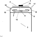
Figur 1- zeigt den Boden des erfindungsgemäßen Sacks mit Innenriegel, Aufreißstreifen und Deckblatt mit Tragegriff.
Figur 2- zeigt die Fixierung des Innenriegels
Figur 3- zeigt Seitenansicht breites Wandteil
Figur 4- zeigt Seitenansicht schmales Wandteil
- FIG. 1
- shows the bottom of the bag according to the invention with inner bar, tear strip and cover sheet with handle.
- FIG. 2
- shows the fixation of the inner bar
- FIG. 3
- shows side view wide wall part
- FIG. 4
- shows side view narrow wall part
- 1 - Kreuzbodensack1 - cross soil bag
- 2, 3 - breites bzw. schmales Wandteil Sack2, 3 - wide or narrow wall section sack
- 4 - Deckblatt4 - cover sheet
- 5 - Tragegriff mit Schnitte 5'5 - carrying handle with cuts 5 '
- 6 - Aufreißstreifen6 - tear strips
- 7 - Innenriegel7 - internal latch
- 8, 9 - Bodeneinschlag8, 9 - Ground impact
- 10, 11 - Seitenlaschen10, 11 - side tabs
- 12, 13 - Seitenkanten der Seitenaschen 10, 1112, 13 - side edges of the side flaps 10, 11
- 14 - Längsachse Boden14 - longitudinal axis of the ground
- 15 - Querachse Boden, senkrecht zu Längsachse15 - transverse axis bottom, perpendicular to the longitudinal axis
- 16, 17 - Falz16, 17 - fold
Gemäß Figuren wird der Kreuzbodensack 1 mit Wandteilen 2 und 3 an einem Ende mittels eines Innenriegels 7 verschlossen, der mit Seitenlaschen 10, 11 und Bodeneinschlag 8, 9 so verbunden ist, so dass kein Füllgut entweichen kann. Seitenlaschen 10, 11 und Innenriegel werden entlang Falz 16, 17 parallel zu Längssache 14 des Bodens gefaltet und verklebt, so dass ein Spalt zwischen den Seitenkanten 12 und 13 der Seitenlaschen über dem Aufreißstreifen bleibt. Darauf wird das Deckblatt 4 angebracht.According to figures, the
Innenriegel und Deckblatt können unabhängig voneinander symmetrisch oder asymmetrisch bezüglich der Längsachse 14 oder der Querachse 15 angebracht werden.Inner bar and cover sheet can be mounted independently of each other symmetrically or asymmetrically with respect to the
Das Deckblatt 4 weist den integrierten Tragegriff 5 auf, der zwischen den Schnitten 5' gebildet wird.The
An Aufreißstreifen 6 kann durch Ziehen der Sack geöffnet werden, wobei der Innenriegel 7 reißt und Deckblatt 4 ohne Einreißen abgelöst wird.At
Claims (15)
- Cross bottom sack having a carrying handle (5) integrated into a cover sheet (4) and having an inner latch (7) with a tear-off strip (6) characterized in that the tear-off strip is fixed on the surface of the inner latch, in the direction of the interior of the sack,
the inner latch and the carrying handle, integrated into the cover sheet, being located in the rigid base and the cover sheet being made of a tear-proof and/or high-tensile material. - The cross bottom sack as claimed in claim 1, characterized in that it is a paper sack.
- The cross bottom sack as claimed in one of the preceding claims, characterized in that it is a valve sack.
- The cross bottom sack as claimed in the preceding claim, characterized in that a cover sheet is fixed to the valve bottom.
- The cross bottom sack as claimed in claim 4, characterized in that the inner latch has a folding at the transverse side in the direction of the interior of the sack.
- The cross bottom sack as claimed in claim 1, characterized in that, in the cover sheet, two cuts are punched out which form the lateral edges of the carrying handle.
- The cross bottom sack as claimed in claim 1, characterized in that the inner latch is folded together with the lateral flaps (10,11) and the surfaces of the inner latch, folded upon each other, are connected with each other.
- The cross bottom sack as claimed in claim 7, characterized in that the paper cover sheet is formed from paper which is reinforced with synthetic material.
- The cross bottom sack as claimed in one of the preceding claims 3 to 5, characterized in that a cover sheet is connected by means of a starch adhesive with the lateral latches and/or the lateral folding.
- The cross bottom sack as claimed in one of the preceding claims, characterized in that the tear-off strip and the carrying handle are arranged one upon the other centrally to the cover sheet.
- The cross bottom sack as claimed in one of the preceding claims, characterized in that it has at least one ventilation device.
- The cross bottom sack as claimed in one of the preceding claims, characterized in that the sack -opposite to the bottom with the carrying handle-has a bottom with a valve and at least one ventilation device A.
- The cross bottom sack as claimed in the preceding claim, characterized in that the surface of the valve, in direction of the exterior of the sack, is partly connected with the ventilation device A, in direction of the interior of the sack, so that one part of the to the interior directing surface of the ventilation device A forms the inner bottom surface of the valve sack in this area and the ventilation device forms a ventilation chamber along the bottom whereby the ventilation chamber is closed on the side of the valve.
- The cross bottom sack as claimed in one of the preceding claims, characterized in that it has a ventilation device B in form of a pocket - open to the interior of the sack - between the folding of the bottom and the two lateral latches, formed by the lateral edges.
- The cross bottom sack as claimed in one of the preceding claims, characterized in that it has a ventilation device C, having an opening in the ventilation device A lengthwise of the bottom, and an opening between the cover sheet of the valve bottom and the underlying lateral latch.
Priority Applications (1)
| Application Number | Priority Date | Filing Date | Title |
|---|---|---|---|
| PL14179507T PL2905236T3 (en) | 2014-02-11 | 2014-08-01 | Hexagonal bottom sack with carrying handle, bottom lining and tear strip |
Applications Claiming Priority (1)
| Application Number | Priority Date | Filing Date | Title |
|---|---|---|---|
| DE202014100593.5U DE202014100593U1 (en) | 2014-02-11 | 2014-02-11 | Cross-bottom bag with carrying handle, inner bar and tear strips |
Publications (2)
| Publication Number | Publication Date |
|---|---|
| EP2905236A1 EP2905236A1 (en) | 2015-08-12 |
| EP2905236B1 true EP2905236B1 (en) | 2017-10-04 |
Family
ID=51015422
Family Applications (1)
| Application Number | Title | Priority Date | Filing Date |
|---|---|---|---|
| EP14179507.0A Active EP2905236B1 (en) | 2014-02-11 | 2014-08-01 | Hexagonal bottom sack with carrying handle, bottom lining and tear strip |
Country Status (3)
| Country | Link |
|---|---|
| EP (1) | EP2905236B1 (en) |
| DE (1) | DE202014100593U1 (en) |
| PL (1) | PL2905236T3 (en) |
Families Citing this family (2)
| Publication number | Priority date | Publication date | Assignee | Title |
|---|---|---|---|---|
| DE202018105191U1 (en) * | 2018-09-11 | 2019-12-12 | Dy-Pack Verpackungen Gustav Dyckerhoff Gmbh | Bag for bulk goods |
| DE102020119749A1 (en) * | 2020-07-27 | 2022-01-27 | Dy-Pack Verpackungen Gustav Dyckerhoff Gmbh | Packing bag and packing method |
Family Cites Families (8)
| Publication number | Priority date | Publication date | Assignee | Title |
|---|---|---|---|---|
| DE4010822A1 (en) | 1990-04-04 | 1991-10-10 | Wilhelmstal Werke Gmbh | Bag or sack made of paper - has tear=off strip in floor for easy opening |
| DE4021801A1 (en) | 1990-04-23 | 1991-10-24 | Windmoeller & Hoelscher | SACK OR BAG WITH FILLED CONDITION OF RECTANGULAR BOTTOM AND STICKED HANDLE |
| DE10352109A1 (en) * | 2003-11-04 | 2005-06-16 | Korsnäs Wilhelmstal GmbH Papiersackfabriken | Paper- or plastic bag has folded base, over which cover strip is fitted which is glued, e.g. along its sides in way allowing it to be removed so that e.g. ingredients printed on reverse can be read |
| DE202006006436U1 (en) | 2006-04-21 | 2006-06-22 | Dy-Pack Verpackungen Gustav Dyckerhoff Gmbh | Paper bag has flat top and base which are connected by tubular walls, cover panel with handle fitted on top panel having tabs at either end which fit over tops of walls |
| DE102007015099A1 (en) | 2007-03-29 | 2008-10-02 | Construction Research & Technology Gmbh | Paper valve bag with inner latch |
| DE202009003080U1 (en) | 2009-03-04 | 2009-04-30 | Dy-Pack Verpackungen Gustav Dyckerhoff Gmbh | paper bags |
| DE102010055777B4 (en) * | 2010-12-23 | 2012-11-22 | Mondi Ag | bag |
| DE202013102644U1 (en) * | 2013-06-19 | 2013-07-24 | Papiersackfabrik Tenax Gmbh & Co. Kg | Valve bag with ventilation devices |
-
2014
- 2014-02-11 DE DE202014100593.5U patent/DE202014100593U1/en not_active Expired - Lifetime
- 2014-08-01 EP EP14179507.0A patent/EP2905236B1/en active Active
- 2014-08-01 PL PL14179507T patent/PL2905236T3/en unknown
Non-Patent Citations (1)
| Title |
|---|
| None * |
Also Published As
| Publication number | Publication date |
|---|---|
| DE202014100593U1 (en) | 2014-06-10 |
| PL2905236T3 (en) | 2018-03-30 |
| EP2905236A1 (en) | 2015-08-12 |
Similar Documents
| Publication | Publication Date | Title |
|---|---|---|
| EP1858769B1 (en) | Paper sack | |
| DE4007649C1 (en) | ||
| DE202007019079U1 (en) | Film packaging bag | |
| EP1600399A1 (en) | Plastic bag for bulk material | |
| WO2008119414A1 (en) | Paper valve sack with inner catch | |
| EP2752371B1 (en) | Valve bag | |
| EP2345595B1 (en) | Valve sack with ventilation device | |
| DE102013008978B4 (en) | Multi-chamber bag, roll of bags with it, film web therefor and method for producing the multi-chamber bag or the roll of bags | |
| EP2905236B1 (en) | Hexagonal bottom sack with carrying handle, bottom lining and tear strip | |
| DE1214598B (en) | Container with a liquid-tight inner bag | |
| DE202014010715U1 (en) | Packaging container for bulk goods | |
| EP2050689A1 (en) | Packaging bag | |
| EP2684813B1 (en) | Valve bag with venting devices | |
| EP0767105A1 (en) | Ventable cross-bottom valve-bag | |
| EP3107816B1 (en) | Bag | |
| DE202011050182U1 (en) | Folding box with inner flap | |
| EP3858755B1 (en) | Bag with side gusset | |
| DE10325175B4 (en) | Closure system for flexible packaging | |
| DE202012006946U1 (en) | Packaging container with ventilation function | |
| DE202010008166U1 (en) | Paper bag with opening device | |
| EP3385189B1 (en) | Stackable valve bag | |
| DE19948191A1 (en) | Plastic foil pouch | |
| EP3812295A1 (en) | Plastic shipping bag and use of the plastic shipping bag | |
| DE102012110145A1 (en) | Transport packaging with stable bottom | |
| DE102012007407A1 (en) | Sack with a sack bottom |
Legal Events
| Date | Code | Title | Description |
|---|---|---|---|
| PUAI | Public reference made under article 153(3) epc to a published international application that has entered the european phase |
Free format text: ORIGINAL CODE: 0009012 |
|
| AK | Designated contracting states |
Kind code of ref document: A1 Designated state(s): AL AT BE BG CH CY CZ DE DK EE ES FI FR GB GR HR HU IE IS IT LI LT LU LV MC MK MT NL NO PL PT RO RS SE SI SK SM TR |
|
| AX | Request for extension of the european patent |
Extension state: BA ME |
|
| 17P | Request for examination filed |
Effective date: 20160211 |
|
| RBV | Designated contracting states (corrected) |
Designated state(s): AL AT BE BG CH CY CZ DE DK EE ES FI FR GB GR HR HU IE IS IT LI LT LU LV MC MK MT NL NO PL PT RO RS SE SI SK SM TR |
|
| 17Q | First examination report despatched |
Effective date: 20160614 |
|
| GRAP | Despatch of communication of intention to grant a patent |
Free format text: ORIGINAL CODE: EPIDOSNIGR1 |
|
| INTG | Intention to grant announced |
Effective date: 20170613 |
|
| GRAA | (expected) grant |
Free format text: ORIGINAL CODE: 0009210 |
|
| GRAS | Grant fee paid |
Free format text: ORIGINAL CODE: EPIDOSNIGR3 |
|
| AK | Designated contracting states |
Kind code of ref document: B1 Designated state(s): AL AT BE BG CH CY CZ DE DK EE ES FI FR GB GR HR HU IE IS IT LI LT LU LV MC MK MT NL NO PL PT RO RS SE SI SK SM TR |
|
| REG | Reference to a national code |
Ref country code: GB Ref legal event code: FG4D Free format text: NOT ENGLISH |
|
| REG | Reference to a national code |
Ref country code: CH Ref legal event code: EP |
|
| REG | Reference to a national code |
Ref country code: AT Ref legal event code: REF Ref document number: 933780 Country of ref document: AT Kind code of ref document: T Effective date: 20171015 |
|
| REG | Reference to a national code |
Ref country code: IE Ref legal event code: FG4D Free format text: LANGUAGE OF EP DOCUMENT: GERMAN |
|
| REG | Reference to a national code |
Ref country code: DE Ref legal event code: R096 Ref document number: 502014005656 Country of ref document: DE |
|
| REG | Reference to a national code |
Ref country code: NL Ref legal event code: FP |
|
| REG | Reference to a national code |
Ref country code: LT Ref legal event code: MG4D |
|
| PG25 | Lapsed in a contracting state [announced via postgrant information from national office to epo] |
Ref country code: FI Free format text: LAPSE BECAUSE OF FAILURE TO SUBMIT A TRANSLATION OF THE DESCRIPTION OR TO PAY THE FEE WITHIN THE PRESCRIBED TIME-LIMIT Effective date: 20171004 Ref country code: SE Free format text: LAPSE BECAUSE OF FAILURE TO SUBMIT A TRANSLATION OF THE DESCRIPTION OR TO PAY THE FEE WITHIN THE PRESCRIBED TIME-LIMIT Effective date: 20171004 Ref country code: ES Free format text: LAPSE BECAUSE OF FAILURE TO SUBMIT A TRANSLATION OF THE DESCRIPTION OR TO PAY THE FEE WITHIN THE PRESCRIBED TIME-LIMIT Effective date: 20171004 Ref country code: LT Free format text: LAPSE BECAUSE OF FAILURE TO SUBMIT A TRANSLATION OF THE DESCRIPTION OR TO PAY THE FEE WITHIN THE PRESCRIBED TIME-LIMIT Effective date: 20171004 Ref country code: NO Free format text: LAPSE BECAUSE OF FAILURE TO SUBMIT A TRANSLATION OF THE DESCRIPTION OR TO PAY THE FEE WITHIN THE PRESCRIBED TIME-LIMIT Effective date: 20180104 |
|
| PG25 | Lapsed in a contracting state [announced via postgrant information from national office to epo] |
Ref country code: GR Free format text: LAPSE BECAUSE OF FAILURE TO SUBMIT A TRANSLATION OF THE DESCRIPTION OR TO PAY THE FEE WITHIN THE PRESCRIBED TIME-LIMIT Effective date: 20180105 Ref country code: BG Free format text: LAPSE BECAUSE OF FAILURE TO SUBMIT A TRANSLATION OF THE DESCRIPTION OR TO PAY THE FEE WITHIN THE PRESCRIBED TIME-LIMIT Effective date: 20180104 Ref country code: IS Free format text: LAPSE BECAUSE OF FAILURE TO SUBMIT A TRANSLATION OF THE DESCRIPTION OR TO PAY THE FEE WITHIN THE PRESCRIBED TIME-LIMIT Effective date: 20180204 Ref country code: RS Free format text: LAPSE BECAUSE OF FAILURE TO SUBMIT A TRANSLATION OF THE DESCRIPTION OR TO PAY THE FEE WITHIN THE PRESCRIBED TIME-LIMIT Effective date: 20171004 Ref country code: LV Free format text: LAPSE BECAUSE OF FAILURE TO SUBMIT A TRANSLATION OF THE DESCRIPTION OR TO PAY THE FEE WITHIN THE PRESCRIBED TIME-LIMIT Effective date: 20171004 Ref country code: HR Free format text: LAPSE BECAUSE OF FAILURE TO SUBMIT A TRANSLATION OF THE DESCRIPTION OR TO PAY THE FEE WITHIN THE PRESCRIBED TIME-LIMIT Effective date: 20171004 |
|
| REG | Reference to a national code |
Ref country code: DE Ref legal event code: R097 Ref document number: 502014005656 Country of ref document: DE |
|
| PG25 | Lapsed in a contracting state [announced via postgrant information from national office to epo] |
Ref country code: CZ Free format text: LAPSE BECAUSE OF FAILURE TO SUBMIT A TRANSLATION OF THE DESCRIPTION OR TO PAY THE FEE WITHIN THE PRESCRIBED TIME-LIMIT Effective date: 20171004 Ref country code: SK Free format text: LAPSE BECAUSE OF FAILURE TO SUBMIT A TRANSLATION OF THE DESCRIPTION OR TO PAY THE FEE WITHIN THE PRESCRIBED TIME-LIMIT Effective date: 20171004 Ref country code: DK Free format text: LAPSE BECAUSE OF FAILURE TO SUBMIT A TRANSLATION OF THE DESCRIPTION OR TO PAY THE FEE WITHIN THE PRESCRIBED TIME-LIMIT Effective date: 20171004 Ref country code: EE Free format text: LAPSE BECAUSE OF FAILURE TO SUBMIT A TRANSLATION OF THE DESCRIPTION OR TO PAY THE FEE WITHIN THE PRESCRIBED TIME-LIMIT Effective date: 20171004 |
|
| PLBE | No opposition filed within time limit |
Free format text: ORIGINAL CODE: 0009261 |
|
| STAA | Information on the status of an ep patent application or granted ep patent |
Free format text: STATUS: NO OPPOSITION FILED WITHIN TIME LIMIT |
|
| REG | Reference to a national code |
Ref country code: FR Ref legal event code: PLFP Year of fee payment: 5 |
|
| PG25 | Lapsed in a contracting state [announced via postgrant information from national office to epo] |
Ref country code: SM Free format text: LAPSE BECAUSE OF FAILURE TO SUBMIT A TRANSLATION OF THE DESCRIPTION OR TO PAY THE FEE WITHIN THE PRESCRIBED TIME-LIMIT Effective date: 20171004 Ref country code: RO Free format text: LAPSE BECAUSE OF FAILURE TO SUBMIT A TRANSLATION OF THE DESCRIPTION OR TO PAY THE FEE WITHIN THE PRESCRIBED TIME-LIMIT Effective date: 20171004 |
|
| 26N | No opposition filed |
Effective date: 20180705 |
|
| PG25 | Lapsed in a contracting state [announced via postgrant information from national office to epo] |
Ref country code: MT Free format text: LAPSE BECAUSE OF FAILURE TO SUBMIT A TRANSLATION OF THE DESCRIPTION OR TO PAY THE FEE WITHIN THE PRESCRIBED TIME-LIMIT Effective date: 20171004 |
|
| PG25 | Lapsed in a contracting state [announced via postgrant information from national office to epo] |
Ref country code: SI Free format text: LAPSE BECAUSE OF FAILURE TO SUBMIT A TRANSLATION OF THE DESCRIPTION OR TO PAY THE FEE WITHIN THE PRESCRIBED TIME-LIMIT Effective date: 20171004 |
|
| REG | Reference to a national code |
Ref country code: DE Ref legal event code: R082 Ref document number: 502014005656 Country of ref document: DE Representative=s name: MEISSNER BOLTE PATENTANWAELTE RECHTSANWAELTE P, DE |
|
| PG25 | Lapsed in a contracting state [announced via postgrant information from national office to epo] |
Ref country code: MC Free format text: LAPSE BECAUSE OF FAILURE TO SUBMIT A TRANSLATION OF THE DESCRIPTION OR TO PAY THE FEE WITHIN THE PRESCRIBED TIME-LIMIT Effective date: 20171004 |
|
| REG | Reference to a national code |
Ref country code: CH Ref legal event code: PL |
|
| GBPC | Gb: european patent ceased through non-payment of renewal fee |
Effective date: 20180801 |
|
| PG25 | Lapsed in a contracting state [announced via postgrant information from national office to epo] |
Ref country code: LI Free format text: LAPSE BECAUSE OF NON-PAYMENT OF DUE FEES Effective date: 20180831 Ref country code: LU Free format text: LAPSE BECAUSE OF NON-PAYMENT OF DUE FEES Effective date: 20180801 Ref country code: CH Free format text: LAPSE BECAUSE OF NON-PAYMENT OF DUE FEES Effective date: 20180831 |
|
| REG | Reference to a national code |
Ref country code: IE Ref legal event code: MM4A |
|
| PG25 | Lapsed in a contracting state [announced via postgrant information from national office to epo] |
Ref country code: IE Free format text: LAPSE BECAUSE OF NON-PAYMENT OF DUE FEES Effective date: 20180801 |
|
| PG25 | Lapsed in a contracting state [announced via postgrant information from national office to epo] |
Ref country code: GB Free format text: LAPSE BECAUSE OF NON-PAYMENT OF DUE FEES Effective date: 20180801 |
|
| PG25 | Lapsed in a contracting state [announced via postgrant information from national office to epo] |
Ref country code: TR Free format text: LAPSE BECAUSE OF FAILURE TO SUBMIT A TRANSLATION OF THE DESCRIPTION OR TO PAY THE FEE WITHIN THE PRESCRIBED TIME-LIMIT Effective date: 20171004 |
|
| PG25 | Lapsed in a contracting state [announced via postgrant information from national office to epo] |
Ref country code: PT Free format text: LAPSE BECAUSE OF FAILURE TO SUBMIT A TRANSLATION OF THE DESCRIPTION OR TO PAY THE FEE WITHIN THE PRESCRIBED TIME-LIMIT Effective date: 20171004 |
|
| REG | Reference to a national code |
Ref country code: DE Ref legal event code: R082 Ref document number: 502014005656 Country of ref document: DE Representative=s name: MEISSNER BOLTE PATENTANWAELTE RECHTSANWAELTE P, DE |
|
| PG25 | Lapsed in a contracting state [announced via postgrant information from national office to epo] |
Ref country code: HU Free format text: LAPSE BECAUSE OF FAILURE TO SUBMIT A TRANSLATION OF THE DESCRIPTION OR TO PAY THE FEE WITHIN THE PRESCRIBED TIME-LIMIT; INVALID AB INITIO Effective date: 20140801 Ref country code: CY Free format text: LAPSE BECAUSE OF FAILURE TO SUBMIT A TRANSLATION OF THE DESCRIPTION OR TO PAY THE FEE WITHIN THE PRESCRIBED TIME-LIMIT Effective date: 20171004 Ref country code: MK Free format text: LAPSE BECAUSE OF NON-PAYMENT OF DUE FEES Effective date: 20171004 |
|
| PG25 | Lapsed in a contracting state [announced via postgrant information from national office to epo] |
Ref country code: AL Free format text: LAPSE BECAUSE OF FAILURE TO SUBMIT A TRANSLATION OF THE DESCRIPTION OR TO PAY THE FEE WITHIN THE PRESCRIBED TIME-LIMIT Effective date: 20171004 |
|
| REG | Reference to a national code |
Ref country code: AT Ref legal event code: MM01 Ref document number: 933780 Country of ref document: AT Kind code of ref document: T Effective date: 20190801 |
|
| PG25 | Lapsed in a contracting state [announced via postgrant information from national office to epo] |
Ref country code: AT Free format text: LAPSE BECAUSE OF NON-PAYMENT OF DUE FEES Effective date: 20190801 |
|
| P01 | Opt-out of the competence of the unified patent court (upc) registered |
Effective date: 20230601 |
|
| PGFP | Annual fee paid to national office [announced via postgrant information from national office to epo] |
Ref country code: NL Payment date: 20230825 Year of fee payment: 10 |
|
| PGFP | Annual fee paid to national office [announced via postgrant information from national office to epo] |
Ref country code: IT Payment date: 20230822 Year of fee payment: 10 |
|
| PGFP | Annual fee paid to national office [announced via postgrant information from national office to epo] |
Ref country code: PL Payment date: 20230707 Year of fee payment: 10 Ref country code: FR Payment date: 20230824 Year of fee payment: 10 Ref country code: DE Payment date: 20230828 Year of fee payment: 10 Ref country code: BE Payment date: 20230825 Year of fee payment: 10 |