EP2905215B2 - Schwimmende plattform mit spannbeinen, insbesondere zur nutzung von windenergie - Google Patents
Schwimmende plattform mit spannbeinen, insbesondere zur nutzung von windenergie Download PDFInfo
- Publication number
- EP2905215B2 EP2905215B2 EP13795810.4A EP13795810A EP2905215B2 EP 2905215 B2 EP2905215 B2 EP 2905215B2 EP 13795810 A EP13795810 A EP 13795810A EP 2905215 B2 EP2905215 B2 EP 2905215B2
- Authority
- EP
- European Patent Office
- Prior art keywords
- floating
- wind energy
- tendons
- bore
- central body
- Prior art date
- Legal status (The legal status is an assumption and is not a legal conclusion. Google has not performed a legal analysis and makes no representation as to the accuracy of the status listed.)
- Active
Links
Images


Classifications
-
- B—PERFORMING OPERATIONS; TRANSPORTING
- B63—SHIPS OR OTHER WATERBORNE VESSELS; RELATED EQUIPMENT
- B63B—SHIPS OR OTHER WATERBORNE VESSELS; EQUIPMENT FOR SHIPPING
- B63B21/00—Tying-up; Shifting, towing, or pushing equipment; Anchoring
- B63B21/50—Anchoring arrangements or methods for special vessels, e.g. for floating drilling platforms or dredgers
- B63B21/502—Anchoring arrangements or methods for special vessels, e.g. for floating drilling platforms or dredgers by means of tension legs
-
- B—PERFORMING OPERATIONS; TRANSPORTING
- B63—SHIPS OR OTHER WATERBORNE VESSELS; RELATED EQUIPMENT
- B63B—SHIPS OR OTHER WATERBORNE VESSELS; EQUIPMENT FOR SHIPPING
- B63B35/00—Vessels or similar floating structures specially adapted for specific purposes and not otherwise provided for
- B63B35/44—Floating buildings, stores, drilling platforms, or workshops, e.g. carrying water-oil separating devices
-
- F—MECHANICAL ENGINEERING; LIGHTING; HEATING; WEAPONS; BLASTING
- F03—MACHINES OR ENGINES FOR LIQUIDS; WIND, SPRING, OR WEIGHT MOTORS; PRODUCING MECHANICAL POWER OR A REACTIVE PROPULSIVE THRUST, NOT OTHERWISE PROVIDED FOR
- F03D—WIND MOTORS
- F03D13/00—Assembly, mounting or commissioning of wind motors; Arrangements specially adapted for transporting wind motor components
- F03D13/20—Arrangements for mounting or supporting wind motors; Masts or towers for wind motors
-
- F—MECHANICAL ENGINEERING; LIGHTING; HEATING; WEAPONS; BLASTING
- F03—MACHINES OR ENGINES FOR LIQUIDS; WIND, SPRING, OR WEIGHT MOTORS; PRODUCING MECHANICAL POWER OR A REACTIVE PROPULSIVE THRUST, NOT OTHERWISE PROVIDED FOR
- F03D—WIND MOTORS
- F03D13/00—Assembly, mounting or commissioning of wind motors; Arrangements specially adapted for transporting wind motor components
- F03D13/20—Arrangements for mounting or supporting wind motors; Masts or towers for wind motors
- F03D13/25—Arrangements for mounting or supporting wind motors; Masts or towers for wind motors specially adapted for offshore installation
-
- F—MECHANICAL ENGINEERING; LIGHTING; HEATING; WEAPONS; BLASTING
- F16—ENGINEERING ELEMENTS AND UNITS; GENERAL MEASURES FOR PRODUCING AND MAINTAINING EFFECTIVE FUNCTIONING OF MACHINES OR INSTALLATIONS; THERMAL INSULATION IN GENERAL
- F16G—BELTS, CABLES, OR ROPES, PREDOMINANTLY USED FOR DRIVING PURPOSES; CHAINS; FITTINGS PREDOMINANTLY USED THEREFOR
- F16G11/00—Means for fastening cables or ropes to one another or to other objects; Caps or sleeves for fixing on cables or ropes
-
- B—PERFORMING OPERATIONS; TRANSPORTING
- B63—SHIPS OR OTHER WATERBORNE VESSELS; RELATED EQUIPMENT
- B63B—SHIPS OR OTHER WATERBORNE VESSELS; EQUIPMENT FOR SHIPPING
- B63B35/00—Vessels or similar floating structures specially adapted for specific purposes and not otherwise provided for
- B63B35/44—Floating buildings, stores, drilling platforms, or workshops, e.g. carrying water-oil separating devices
- B63B2035/4433—Floating structures carrying electric power plants
- B63B2035/446—Floating structures carrying electric power plants for converting wind energy into electric energy
-
- Y—GENERAL TAGGING OF NEW TECHNOLOGICAL DEVELOPMENTS; GENERAL TAGGING OF CROSS-SECTIONAL TECHNOLOGIES SPANNING OVER SEVERAL SECTIONS OF THE IPC; TECHNICAL SUBJECTS COVERED BY FORMER USPC CROSS-REFERENCE ART COLLECTIONS [XRACs] AND DIGESTS
- Y02—TECHNOLOGIES OR APPLICATIONS FOR MITIGATION OR ADAPTATION AGAINST CLIMATE CHANGE
- Y02E—REDUCTION OF GREENHOUSE GAS [GHG] EMISSIONS, RELATED TO ENERGY GENERATION, TRANSMISSION OR DISTRIBUTION
- Y02E10/00—Energy generation through renewable energy sources
- Y02E10/70—Wind energy
- Y02E10/72—Wind turbines with rotation axis in wind direction
-
- Y—GENERAL TAGGING OF NEW TECHNOLOGICAL DEVELOPMENTS; GENERAL TAGGING OF CROSS-SECTIONAL TECHNOLOGIES SPANNING OVER SEVERAL SECTIONS OF THE IPC; TECHNICAL SUBJECTS COVERED BY FORMER USPC CROSS-REFERENCE ART COLLECTIONS [XRACs] AND DIGESTS
- Y02—TECHNOLOGIES OR APPLICATIONS FOR MITIGATION OR ADAPTATION AGAINST CLIMATE CHANGE
- Y02E—REDUCTION OF GREENHOUSE GAS [GHG] EMISSIONS, RELATED TO ENERGY GENERATION, TRANSMISSION OR DISTRIBUTION
- Y02E10/00—Energy generation through renewable energy sources
- Y02E10/70—Wind energy
- Y02E10/727—Offshore wind turbines
-
- Y—GENERAL TAGGING OF NEW TECHNOLOGICAL DEVELOPMENTS; GENERAL TAGGING OF CROSS-SECTIONAL TECHNOLOGIES SPANNING OVER SEVERAL SECTIONS OF THE IPC; TECHNICAL SUBJECTS COVERED BY FORMER USPC CROSS-REFERENCE ART COLLECTIONS [XRACs] AND DIGESTS
- Y02—TECHNOLOGIES OR APPLICATIONS FOR MITIGATION OR ADAPTATION AGAINST CLIMATE CHANGE
- Y02E—REDUCTION OF GREENHOUSE GAS [GHG] EMISSIONS, RELATED TO ENERGY GENERATION, TRANSMISSION OR DISTRIBUTION
- Y02E10/00—Energy generation through renewable energy sources
- Y02E10/70—Wind energy
- Y02E10/728—Onshore wind turbines
Definitions
- the present invention may be included in the technical field for the generation of electrical power, in particular for obtaining electrical power from the wind and/or other renewable sources as for example tides, waves and currents, in offshore facilities.
- the object of the invention refers to a floating platform to be especially applied to the offshore and/or hybrid wind power utilisation.
- Floating tension-leg platforms are terms referring to floating structures partially submerged in the sea, which are anchored to the sea bed by means of anchoring elements which work by traction, and wherein said structures keep their static position thanks to the balance between thrust forces due to flotation, and fastening forces generated by the anchoring elements, since the thrust forces are strong enough as to produce the required traction in the anchoring elements.
- Document GB2378679A discloses a floating tension-leg platform, to be especially applied for wind energy utilisation, comprising a floating structure which in turns comprises a single floating central body, provided with an elongated configuration according to a longitudinal direction, being the central body provided with an upper portion and a lower portion, wherein the lower portion is intended to be submerged,
- the present invention solves the technical problem stated, by means of a tension floating platform to be especially applied for obtaining electrical power from wind power and/or other renewable sources in sea facilities.
- the platform of the invention comprises a single floating central body.
- the central body has a configuration which is elongated with respect to a longitudinal direction which, when in use, is substantially vertical.
- the central body features rotational symmetry around an axis oriented according to the longitudinal direction.
- the central body may comprise one of several cylindrical and/or tapered segments longitudinally arranged.
- the central body a lower and an upper portion can be distinguished.
- the lower portion of the central body is intended to be submerged up to an altitude referred to as draft.
- the upper portion of the central body comprises a top end provided with a base, on which a wind turbine will be arranged supported by the platform of the invention.
- the wind turbine may have either a vertical axis or a horizontal axis, and in this last case it may be either two or three bladed.
- At least four legs (also referred to as pontoons) extending outwardly, come out from the lower portion of the central body.
- the central body and the legs together constitute a floating structure.
- the legs confer stability to the floating structure, fundamentally against overturning.
- the legs comprise a first end, by which they are attached to the lower portion of a central body, and a second end, opposing the first end, and more distantly spaced from said central body.
- the floating platform of the invention additionally incorporates, as it is explained below, porches placed in the second ends of the legs; anchoring elements to anchor the legs to the sea bed; and tendons provided with upper ends and lower ends, wherein the upper ends are connected to the porches and the lower ends are connected to the anchoring elements.
- the anchoring elements are preferably piles driven into the sea bed.
- Tendons are elongated elements intended to support traction strains. They can adopt several configurations, for example: steel cables, synthetic material cables and steel tubes.
- each tendon there is a cable clamp arranged, for connecting the tendon with its corresponding bracket, cooperating with a first connector.
- Each first connector comprises an upper end and a lower end, wherein the upper end comprises an upper bore for articulating the connector and the cable clamp, whereas the lower end comprises a lower bore not parallel to the upper bore, preferably perpendicular, for articulating the first connector with a tendon.
- the non-parallel arrangement of an upper bore and a lower bore enables the first connector to provide a relative rotation between each tendon and its porch around two axes, consequently preventing the unnecessary transmission of torsional stress between tendon and bracket.
- each bracket located in each of the second ends of the legs.
- Each one of the porches incorporates a through bore in a vertical direction to accommodate connecting means intended to be connected to the first connector of a tendon.
- Anchoring elements are driven into the sea bed, the upper part of which projects from the sea bed and is provided with fixing means to connect the tendons lower ends.
- the tendons connecting the floating structure legs to the anchoring elements anchored to the sea bed, are subjected to traction strains which are transmitted to the structure, so as to keep said structure fixed in the sea.
- the tendons tension limits the movements in a vertical direction
- tendons attachment to the anchoring elements and the legs porches limits the horizontal movements and overturning.
- the arrangement of at least four legs confers stability to the floating structure in case that tendons from one of the legs break. In fact, if the tendon or tendons from one of the legs fail, the at least three remaining legs may provide stability to the floating structure, so that the floating structure stands, even though it can eventually be out of work. In case of failure of the tendons from one of the legs when there are only three legs, overturning of the floating structure would be imminent.
- the present invention disclosures a tension floating platform to be used in the field of wind power utilisation in sea areas, being lighter and more manageably than the TLPs used in offshore hydrocarbons exploitation, and having better operational conditions than other floating platforms designed for wind exploitation.
- the invention may additionally incorporate a device intended for wave energy utilisation, which is preferably arranged floating at water level and attached by means of guides to the central body of the platform.
- the legs and the central body of the floating platform are divided into compartments, and the platform additionally incorporates a set of pumps and a control system, to pump and extract liquid (usually water) from the compartments, and thus change the platform draft conveniently, to carry out floating, transport and mooring operations.
- a set of pumps and a control system to pump and extract liquid (usually water) from the compartments, and thus change the platform draft conveniently, to carry out floating, transport and mooring operations.
- the floating tension-leg platform for wind source utilisation in the sea comprises a floating structure formed by a single floating central body (1) and at least four legs (2) coming out from the central body (1).
- the central body (1) features a configuration which is elongated with respect to a longitudinal direction which is substantially vertical, as well as the central body (1) is provided with rotational symmetry around an axis oriented according to the longitudinal direction.
- the central body (1) comprises a lower portion and an upper portion.
- the lower portion is submerged up to an altitude referred to as draft.
- the upper portion comprises a top end provided with a base (3) on which a wind turbine (4) is placed supported by the floating structure.
- the lower portion of the central body (1) comprises a lower end from which four legs (2) come out, arranged symmetrically and at equidistant angles in the lower end perimeter.
- the legs (2) comprise a first end, by means of which they are integrally attached to the central body (1), and a second end, opposing the first end, and more distant from the central body (1).
- the platform of the invention additionally includes, as it will be explained below, brackets (6), shown in more detailed in figures 2 and 4 , and which are located in the second ends of the legs (2); anchoring elements, preferably piles (7) partially driven into the sea bed (5) and shown in more detailed in figure 3 ; and tendons (8) each provided with upper ends connected to the porches (6), as well as lower ends connected to the piles (7), see figure 1 .
- the tendons (8) are elongated elements intended to support traction strains.
- said tendons (8) comprise first connecting means (13) to connect each tendon (8) to its corresponding porch (6), as it will be explained below.
- the invention additionally includes cable clamps (40), cooperating with first connectors (9), see figure 4 .
- the cable clamps (40) are arranged in the upper end of the tendons (8), whereas the first connectors (9) comprise an upper end and a lower end, wherein the upper end comprises an upper bore (11), for articulating the first connector (9) to its tendon (8), whereas the lower end comprises a lower bore (10) perpendicular to the upper bore (11), for articulating the first connector (9) with its corresponding tendon (8).
- the first connectors (9) have a substantially parallelepiped shape defined by four side faces (14, 15), which comprise two first side faces (14) opposite to each other and two second side faces (15), also opposite to each other and perpendicular to the first side faces (14).
- an upper groove (18) being in the upper end of the first connector (9) goes through the two second side faces (15), leaving the upper end open in said second side faces (15) and defining in each of the first side faces (14) second lugs (19) separated by the upper groove (18).
- the lower through bore (10) goes through the first lugs (17), same as the upper through bore (11) goes through the second lugs (19).
- the cable clamps (40) comprise a lower end attached to the upper end of each tendon (8), comprising as well an flat upper end provided with a first hole (22), wherein said upper end is to be inserted in the lower groove (16), with the lower bore (10) facing the first hole (22), so that each cable clamp (40) is connectable with the first connector (9) through the first bolt (23) going through the lower bore (10) and the first hole (22).
- each one of the second ends of the legs (2) there is at least a porch (6) arranged for connecting a tendon (8) to the legs (2), leaving a rotation with respect to an axis oriented according to the longitudinal direction of the tendon (8) as degree of freedom between the tendon (8) and the bracket (6).
- Each one of the porches (6) includes a first through drilling (12) in vertical direction to accommodate second connecting means (24).
- the second connecting means (24) comprise a connecting body (25) provided with an upper end and a lower end. In the upper end of the connecting body (25), there is a stopper (26) to keep the upper end of the connecting body (25) outside the first drilling (12).
- the lower end of the connecting body (25) is flat and is provided with a second hole (27), wherein said lower end is to be inserted in the upper groove (18), so that the second connecting means (24) is connectable to the first connector (9) through a second bolt (28) which goes through the upper bore (11) and the second hole (27).
- piles (7) driven into the sea bed (5), the upper portion of which projects from the sea bed (5) and is provided with fixing means to connect the lower ends of the tendons (8).
- the piles (7) are provided to be distributed in as many assemblies as legs (2) comprised in the floating structure, where each assembly preferably comprises as many piles (7) as brackets (6) found in each leg (2).
- the piles (7) of the same assembly may be integral to each other, being attached at their upper portion through joining plates (29).
- joining plates (29) there are fixing means arranged, as well as a plurality of sacrificial anodes (30).
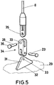
- the fixing means include a plurality of plates (31), preferably having a triangular base, wherein one of the side faces (32) of each plate (31) is fixed to the joining plate (29).
- the plate (31) comprises, preferably near the vertex more distant from the joining plate (29), a third hole (33).
- the lower portion of the tendons (8) include third connecting means provided with a first end fixed to the lower end of the tendons (8), and with a second end provided with a second drilling (35), wherein the second end enables to seize the plate (31) on both sides of said plate (31) in the third hole (33) area, being the third hole (33) and the second drilling (35) opposite to each other, so that a third bolt (36) can be inserted simultaneously in the third hole (33) and in the second drilling (35) to fix the tendon (8) to the plate (31).
- the third connecting means comprise a second connector (9) shown in figure 4 , which permits the fixation between tendons (8) and plates (31) to avoid unnecessary transmission of torsional stress.
- the piles (7) may be suction piles (7), in such a way that, in the joining plates (29), there are mouths (37) arranged to connect a pump (not shown) producing the required suction to insert the piles (7) of each of the assemblies.
Landscapes
- Engineering & Computer Science (AREA)
- Mechanical Engineering (AREA)
- Chemical & Material Sciences (AREA)
- Combustion & Propulsion (AREA)
- Ocean & Marine Engineering (AREA)
- General Engineering & Computer Science (AREA)
- Life Sciences & Earth Sciences (AREA)
- Sustainable Development (AREA)
- Sustainable Energy (AREA)
- Civil Engineering (AREA)
- Structural Engineering (AREA)
- Architecture (AREA)
- Wind Motors (AREA)
Claims (10)
- Schwimmende Plattform mit Spannbeinen, die insbesondere zur Nutzung von Windenergie angewandt wird und eine schwimmende Struktur umfasst, die ihrerseits einen einzelnen, zentralen Schwimmkörper (1) umfasst, ausgestattet mit einer länglichen Konfiguration entsprechend einer Längsrichtung, wobei der zentrale Körper (1) mit einem oberen Teil und einem unteren Teil ausgestattet ist, wobei der untere Teil dazu vorgesehen ist, untergetaucht zu werden, wobei diese zusätzlich Folgendes umfasst:- eine Basis (3), die sich im oberen Teil des zentralen Körpers (1) befindet und dazu vorgesehen ist, mindestens eine Windturbine (4) zu stützen;- mindestens vier Beine (2), die sich im unteren Teil des zentralen Körpers (1) befinden und mit Folgenden ausgestattet sind:- ein erstes Ende, mit dem diese integral am zentralen Körper (1) befestigt sind,- ein zweites Ende gegenüber dem ersten Ende und mit einem größeren Abstand zum zentralen Körper (1), und- mindestens einen Vorbau (6), der sich im zweiten Ende jedes Beins (2) befindet, wobei dieser Vorbau (6) eine erste Bohrung (12) in Längsrichtung umfasst, um die schwimmende Plattform am Meeresboden (5) zu verankern;- Verankerungselemente zur Befestigung der Beine (2) am Meeresboden (5); und- eine Vielzahl von Spanngliedern (8), die eine längliche Konfiguration besitzen und dazu ausgelegt sind, Zugbelastungen zu widerstehen, wobei die Spannglieder (8) Folgendes umfassen:wobei der zentrale Körper (1) und die Beine (2) gemeinsam die schwimmende Struktur bilden, wobei die Beine (2) und der zentrale Körper (1) in Kompartimente unterteilt sind und wobei die Plattform ferner Folgendes umfasst:- obere Enden, die dazu vorgesehen sind, mit den Vorbauten (6) verbunden zu werden, und- untere Enden, die dazu vorgesehen sind, mit den Verankerungselementen verbunden zu werden;- eine Reihe von Pumpen und ein Steuerungssystem, um Flüssigkeit aus den Kompartimenten zu pumpen und zu fördern und somit das Plattformkonzept in geeigneter Weise zu verändern, um Schwimm-, Transport- und Vertäuungsmanöver durchzuführen.
- Schwimmende Plattform mit Spannbeinen nach Anspruch 1, die insbesondere zur Nutzung von Windenergie angewandt wird, dadurch gekennzeichnet, dass diese zusätzlich Folgendes umfasst:- eine Kabelklemme (40), die im oberen Ende jedes Spannglieds (8) montiert ist, um dieses Spannglied (8) mit dessen Vorbau (6) zu verbinden, und- einen ersten Stecker (9), umfassend:- ein oberes Ende, das mit einer oberen Bohrung (11) zur gelenkigen Anordnung des ersten Steckers (9) mit der Kabelklemme (40) ausgestattet ist, und- ein unteres Ende, das mit einer unteren Bohrung (10) nicht parallel zur oberen Bohrung (11) ausgestattet ist, zur gelenkigen Anordnung des ersten Steckers (9) mit einem Spannglied (8).
- Schwimmende Plattform mit Spannbeinen nach Anspruch 2, die insbesondere zur Nutzung von Windenergie angewandt wird, dadurch gekennzeichnet, dass die obere Bohrung (11) und die untere Bohrung (12) senkrechte Richtungen aufweisen.
- Schwimmende Plattform mit Spannbeinen nach einem der Ansprüche 2 und 3, die insbesondere zur Nutzung von Windenergie angewandt wird, dadurch gekennzeichnet, dass die ersten Stecker (9) eine im Wesentlichen parallelflache Form besitzen, die von Seitenflächen (14, 15) definiert wird, wobei die ersten Stecker (9) Folgendes umfassen:- zwei erste Seitenflächen (14), die einander gegenüber liegen; und- zwei zweite Seitenflächen (15), die ebenfalls einander gegenüber liegen, wobei die ersten Stecker (9) zusätzlich Folgendes umfassen:- ein oberes Ende;- ein unteres Ende;- eine untere Nut (16), die sich im oberen Ende des ersten Steckers (9) befindet und durch die zwei ersten Seitenflächen (14) verläuft, das untere Ende in diesen ersten Seitenflächen (14) offen lässt und in jeder der zweiten Seitenflächen (15) erste Ösen (17) definiert, die von der unteren Nut (16) getrennt werden;- eine obere Nut (18), die sich im oberen Ende des ersten Steckers (9) befindet und durch die zwei zweiten Seitenflächen (15) verläuft, das obere Ende in diesen zweiten Seitenflächen (15) offen lässt und in jeder der ersten Seitenflächen (14) zweite Ösen (19) definiert, die von der oberen Nut (18) getrennt werden;wobei die untere Durchgangsbohrung (10) durch die ersten Ösen (17) verläuft und die obere Durchgangsbohrung (11) durch die zweiten Ösen (19) verläuft.
- Schwimmende Plattform mit Spannbeinen nach Anspruch 4, die insbesondere zur Nutzung von Windenergie angewandt wird, dadurch gekennzeichnet, dass die Spannglieder (8) zusätzlich erste Verbindungsmittel (13) einschließen, die sich in den oberen Enden der Spannglieder (8) befinden, um jedes Spannglied (8) mit dessen entsprechendem Vorbau (6) zu verbinden, wobei die ersten Verbindungsmittel (13) Folgendes umfassen:- ein unteres Ende, das mit dem oberen Ende jedes Spannglieds (8) verbunden ist und- ein flaches, oberes Ende, das mit einem ersten Loch (22) ausgestattet ist, wobei dieses obere Ende in die untere Nut (16) eingeführt wird und die untere Bohrung (10) dem ersten Loch (22) zugewandt ist.
- Schwimmende Plattform mit Spannbeinen nach Anspruch 4, die insbesondere zur Nutzung von Windenergie angewandt wird, dadurch gekennzeichnet, dass diese zusätzlich zweite Verbindungsmittel (24) einschließt, die in die ersten Bohrungen (12) eingeführt werden, um Vorbauten (6) mit Spanngliedern (8) zu verbinden, wobei die zweiten Verbindungsmittel (24) Folgendes umfassen:- ein Verbindungsgehäuse (25), das mit einem oberen Ende und einem flachen unteren Ende ausgestattet ist;- einen Stopper (26), der sich in einem unteren Ende des Verbindungsgehäuses (25) befindet, um dieses obere Ende außerhalb der ersten Bohrung (12) zu halten;- ein zweites Loch (27), das sich im unteren Ende des Verbindungsgehäuses (25) befindet, wobei dieses untere Ende in die obere Nut (18) eingeführt wird und das zweite Loch (27) der oberen Bohrung (11) zugewandt ist.
- Schwimmende Plattform mit Spannbeinen nach Anspruch 1, die insbesondere zur Nutzung von Windenergie angewandt wird, dadurch gekennzeichnet, dass es sich bei den Verankerungselementen um Pfähle (7) handelt, die mindestens teilweise in den Meeresboden (5) getrieben werden.
- Schwimmende Plattform mit Spannbeinen nach Anspruch 7, die insbesondere zur Nutzung von Windenergie angewandt wird, dadurch gekennzeichnet, dass die Pfähle (7) in genau so viele Baugruppen unterteilt sind, wie Beine (2) in der schwimmenden Struktur umfasst sind, wobei jede Pfahlbaugruppe (7) so viele Pfähle (7) umfasst, wie Vorbauten (6) an jedem Bein (2) vorhanden sind.
- Schwimmende Plattform mit Spannbeinen nach einem der Ansprüche 7 und 8, die insbesondere zur Nutzung von Windenergie angewandt wird, dadurch gekennzeichnet, dass diese zusätzlich eine Verbindungsplatte (29) umfasst, die im oberen Teil von mindestens einer Pfahlbaugruppe (7) angeordnet ist, um die Pfähle (7) derselben Baugruppe miteinander zu integrieren.
- Schwimmende Plattform mit Spannbeinen nach einem der Ansprüche 7 bis 9, die insbesondere zur Nutzung von Windenergie angewandt wird, dadurch gekennzeichnet, dass der obere Teil der Pfähle (7) Befestigungsmittel umfasst, um die Pfähle (7) mit den unteren Enden der Spannglieder (8) zu verbinden, wobei die Befestigungsmittel eine Vielzahl von Platten (31) umfassen, umfassend:- mindestens eine Seitenfläche (32), die am oberen Teil des Pfahls (7) befestigt ist; und- ein drittes Loch (33);wobei die Spannglieder (8) zusätzlich an deren unterem Ende dritte Verbindungsmittel (34) umfassen, umfassend:- ein erstes Ende, das am unteren Ende der Spannglieder (8) befestigt ist; und- ein zweites Ende, das die Arretierung der Platte (31) im Bereich des dritten Lochs (33) ermöglicht, wobei das dritte Loch (33) und die zweite Bohrung (35) einander gegenüber liegen.
Applications Claiming Priority (2)
| Application Number | Priority Date | Filing Date | Title |
|---|---|---|---|
| ES201231547A ES2454044B1 (es) | 2012-10-08 | 2012-10-08 | Plataforma flotante en tensión de especial aplicación para aprovechamiento eólico |
| PCT/ES2013/070695 WO2014057154A1 (es) | 2012-10-08 | 2013-10-08 | Plataforma flotante en tensión de especial aplicación para aprovechamiento eólico |
Publications (3)
| Publication Number | Publication Date |
|---|---|
| EP2905215A1 EP2905215A1 (de) | 2015-08-12 |
| EP2905215B1 EP2905215B1 (de) | 2017-02-01 |
| EP2905215B2 true EP2905215B2 (de) | 2020-06-10 |
Family
ID=49667180
Family Applications (1)
| Application Number | Title | Priority Date | Filing Date |
|---|---|---|---|
| EP13795810.4A Active EP2905215B2 (de) | 2012-10-08 | 2013-10-08 | Schwimmende plattform mit spannbeinen, insbesondere zur nutzung von windenergie |
Country Status (6)
| Country | Link |
|---|---|
| US (1) | US9573662B2 (de) |
| EP (1) | EP2905215B2 (de) |
| JP (1) | JP6498604B2 (de) |
| ES (1) | ES2454044B1 (de) |
| PT (1) | PT2905215T (de) |
| WO (1) | WO2014057154A1 (de) |
Families Citing this family (32)
| Publication number | Priority date | Publication date | Assignee | Title |
|---|---|---|---|---|
| PL237283B1 (pl) * | 2013-12-06 | 2021-04-06 | Piskorz Ireneusz | Wielosegmentowa turbina wiatrowa |
| GB201509527D0 (en) * | 2015-06-02 | 2015-07-15 | Axis Energy Projects Ltd | System and method |
| US10024021B2 (en) * | 2016-02-11 | 2018-07-17 | Daniel I. Corbett | Anchoring system |
| JP6914953B2 (ja) * | 2016-02-24 | 2021-08-04 | エフエム・エネルギー・ゲーエムベーハー・ウント・コンパニー・カーゲー | 弾性ボール/振り子軸受を有する風力発電機 |
| US11650120B2 (en) * | 2016-02-29 | 2023-05-16 | Richard V. Campbell | Intelligent cable module calibration system and method |
| US11162856B2 (en) * | 2016-02-29 | 2021-11-02 | Richard V. Campbell | Intelligent fiber rope termination, module, and networking technologies |
| US10451504B2 (en) * | 2016-02-29 | 2019-10-22 | Bright Technologies, Llc | Intelligent fiber rope termination |
| US11162855B2 (en) * | 2016-02-29 | 2021-11-02 | Richard V. Campbell | Intelligent fiber rope termination, module, and networking technologies |
| CN106741688B (zh) * | 2016-12-02 | 2018-05-04 | 大连理工大学 | 一种水下组合式生产输送立管系统及其安装方法 |
| CN106697208B (zh) * | 2016-12-02 | 2018-05-04 | 大连理工大学 | 一种水下集成式生产输送立管系统及其安装方法 |
| CN106741687B (zh) * | 2016-12-02 | 2018-09-04 | 大连理工大学 | 一种水下自张紧式生产输送立管系统及其安装方法 |
| CN106585910B (zh) * | 2016-12-02 | 2018-05-04 | 大连理工大学 | 一种立管自张紧式水下生产支撑浮筒及其安装与回收方法 |
| GB201622129D0 (en) | 2016-12-23 | 2017-02-08 | Statoil Petroleum As | Subsea assembly modularisation |
| US10676952B2 (en) * | 2018-01-26 | 2020-06-09 | General Electric Company | System and method for stabilizing a wind turbine |
| KR102903196B1 (ko) * | 2018-12-19 | 2025-12-23 | 싱글 뷰이 무어링스 인크. | 계류 어레인지먼트를 위한 요크 플레이트 어셈블리 및 이 요크 플레이트 어셈블리를 포함하는 계류 어레인지먼트 |
| US11014637B2 (en) | 2019-02-21 | 2021-05-25 | Vl Offshore, Llc | Motion-attenuated semi-submersible floating-type foundation for supporting a wind power generation system |
| US11939032B2 (en) | 2019-02-21 | 2024-03-26 | Vl Offshore, Llc | Floating-type foundation for supporting a wind power generation system and including a stabilized power cable, system of floating-type foundations, and a method of stabilizing the power cable |
| CN112664032B (zh) * | 2019-10-16 | 2022-12-09 | 北京金风科创风电设备有限公司 | 拉索锚固装置、拉索式塔架及风力发电机组 |
| US12049286B1 (en) * | 2019-11-21 | 2024-07-30 | NuEnergy Partners, LP | Tendon support buoyancy system and method |
| KR102144424B1 (ko) * | 2020-03-27 | 2020-08-12 | (주)삼원밀레니어 | 인장계류식 풍력발전기 및 이의 설치 및 해체 방법 |
| NO346067B1 (en) * | 2020-06-11 | 2022-01-31 | Oddmund Vik | Floating windmill |
| JP7307092B2 (ja) * | 2020-09-01 | 2023-07-11 | 三井海洋開発株式会社 | 張力脚プラットフォームテザーの長さを調整するためのシステムおよび方法 |
| GB2598616A (en) | 2020-09-04 | 2022-03-09 | Riggmor As | Floating body and mooring system |
| US20230415855A1 (en) | 2020-10-01 | 2023-12-28 | Petroliam Nasional Berhad (Petronas) | An improved floating offshore structure |
| ES2936557B2 (es) * | 2021-09-17 | 2023-07-25 | Bluenewables Sl | Dispositivo de plataforma flotante para torre eolica y metodo de montaje |
| EP4201798A1 (de) * | 2021-12-24 | 2023-06-28 | TotalEnergies OneTech | Verankerungsvorrichtung für eine offshore-windkraftanlage |
| US11422047B1 (en) | 2022-01-08 | 2022-08-23 | Astro Technology Group, Llc | Systems, devices and methods for monitoring support platform structural conditions |
| AU2023208543A1 (en) * | 2022-01-21 | 2024-06-20 | Entrion Wind, Inc. | Mooring systems for fixed marine structures |
| US11698291B1 (en) | 2022-06-10 | 2023-07-11 | Astro Technology Group, Llc | Pipeline condition sensing for protecting against theft of a substance flowing through a pipeline |
| US12404043B2 (en) | 2022-06-20 | 2025-09-02 | Astro Technology Group, Llc | System and method for monitoring activity and/or environment conditions of an area surrounding a pipeline |
| CN115822880A (zh) * | 2022-10-24 | 2023-03-21 | 深圳深德海洋工程有限公司 | 一种张力腿式海上风力发电平台基础及系泊系统 |
| CN119373668B (zh) * | 2024-12-27 | 2025-03-11 | 上海交通大学三亚崖州湾深海科技研究院 | 一种具有双腱协调机构的浮式风机装置 |
Family Cites Families (28)
| Publication number | Priority date | Publication date | Assignee | Title |
|---|---|---|---|---|
| JPS4845533Y1 (de) * | 1968-12-24 | 1973-12-27 | ||
| US4082050A (en) * | 1976-08-30 | 1978-04-04 | Single Buoy Moorings, Inc. | Coupling between an anchor under water and a buoyant body |
| JPS6149029A (ja) * | 1984-08-13 | 1986-03-10 | Nippon Steel Corp | 水中基礎固定装置 |
| JP2597478B2 (ja) * | 1986-05-22 | 1997-04-09 | 大成建設株式会社 | 係留索の連結方法 |
| US4907914A (en) | 1987-05-11 | 1990-03-13 | Exxon Production Research Company | Tether connector for a tension leg platform |
| JPS642692U (de) * | 1987-06-26 | 1989-01-09 | ||
| JPH02283590A (ja) * | 1989-04-24 | 1990-11-21 | Mitsui Eng & Shipbuild Co Ltd | テンションレグプラットフォームのテンドン接続装置 |
| US5381865A (en) | 1990-12-13 | 1995-01-17 | Blandford; Joseph W. | Method and apparatus for production of subsea hydrocarbon formations |
| JP2755834B2 (ja) * | 1991-02-07 | 1998-05-25 | 三菱重工業株式会社 | 海中条体配設装置 |
| GB9221542D0 (en) | 1992-10-14 | 1992-11-25 | Bluewater Terminal System Nv | Single point mooring terminals |
| US5551802A (en) * | 1993-02-08 | 1996-09-03 | Sea Engineering Associates, Inc. | Tension leg platform and method of installation therefor |
| US5421676A (en) * | 1993-02-08 | 1995-06-06 | Sea Engineering Associates, Inc. | Tension leg platform and method of instalation therefor |
| USH1246H (en) | 1993-05-26 | 1993-11-02 | Exxon Production Research Company | Buoyant cable tether |
| JPH08189282A (ja) * | 1995-01-09 | 1996-07-23 | Imodco Inc | 海底炭化水素生産システム、および炭化水素生産のために海底源泉プラットフォームを設置するための方法 |
| US5964550A (en) * | 1996-05-31 | 1999-10-12 | Seahorse Equipment Corporation | Minimal production platform for small deep water reserves |
| DE10034847A1 (de) | 2000-07-18 | 2002-02-14 | Maierform Maritime Technology | Ortsfeste Positionierung von Funktionseinheiten auf dem oder im Wasser |
| GB0119969D0 (en) | 2001-08-16 | 2001-10-10 | Ocean Technologies Ltd | Floating offshore windtower |
| US20040105725A1 (en) * | 2002-08-05 | 2004-06-03 | Leverette Steven J. | Ultra-deepwater tendon systems |
| WO2004079146A2 (en) * | 2003-02-28 | 2004-09-16 | Modec International, L.L.C. | Method of installation of a tension leg platform |
| ITBA20040027U1 (it) * | 2004-10-06 | 2005-01-06 | Enertec Ag | (metodo di) realizzazione di piattaforma sommergibile a spinta bloccata da utilizzarsi quale supporto per l'installazione di aerogeneratore , di elettrolizzatore per l'elettrolisi dell'acqua e di altri impianti e/o macchinari , combinata con attivita |
| ITTO20070666A1 (it) * | 2007-09-24 | 2009-03-25 | Blue H Intellectual Properties | Sistema di conversione di energia eolica offshore per acque profonde |
| US20090078425A1 (en) | 2007-09-25 | 2009-03-26 | Seahorse Equipment Corp | Flexible hang-off arrangement for a catenary riser |
| CN201145003Y (zh) * | 2007-12-27 | 2008-11-05 | 山东省科学院海洋仪器仪表研究所 | 隔振降噪万向连接装置 |
| DE102008003647B4 (de) * | 2008-01-09 | 2011-12-15 | Gicon Windpower Ip Gmbh | Schwimmendes Gründungstragwerk mit Auftriebskomponenten, in aufgelöster Bauweise |
| JP2010018129A (ja) * | 2008-07-09 | 2010-01-28 | Mitsui Eng & Shipbuild Co Ltd | 緊張係留浮体の傾斜調整方法及び緊張係留浮体 |
| DE102009044278A1 (de) * | 2009-10-16 | 2011-04-21 | JÄHNIG, Jens | Schwimmfundament mit verbesserter Abspannung |
| GB2482198B (en) * | 2010-07-23 | 2013-09-11 | Paul A Frieze & Associates Ltd | Tension leg support structures |
| WO2012097283A2 (en) * | 2011-01-14 | 2012-07-19 | The Glosten Associates, Inc. | Installation method for water-submersible platforms and installation vessel |
-
2012
- 2012-10-08 ES ES201231547A patent/ES2454044B1/es not_active Expired - Fee Related
-
2013
- 2013-10-08 WO PCT/ES2013/070695 patent/WO2014057154A1/es not_active Ceased
- 2013-10-08 JP JP2015535071A patent/JP6498604B2/ja active Active
- 2013-10-08 PT PT137958104T patent/PT2905215T/pt unknown
- 2013-10-08 US US14/434,035 patent/US9573662B2/en active Active
- 2013-10-08 EP EP13795810.4A patent/EP2905215B2/de active Active
Also Published As
| Publication number | Publication date |
|---|---|
| EP2905215B1 (de) | 2017-02-01 |
| WO2014057154A1 (es) | 2014-04-17 |
| JP6498604B2 (ja) | 2019-04-10 |
| ES2454044A1 (es) | 2014-04-09 |
| US9573662B2 (en) | 2017-02-21 |
| EP2905215A1 (de) | 2015-08-12 |
| JP2015533110A (ja) | 2015-11-19 |
| US20150259044A1 (en) | 2015-09-17 |
| PT2905215T (pt) | 2017-05-10 |
| ES2454044B1 (es) | 2015-03-10 |
Similar Documents
| Publication | Publication Date | Title |
|---|---|---|
| EP2905215B1 (de) | Schwimmende plattform mit spannbeinen, insbesondere zur nutzung von windenergie | |
| US8568063B2 (en) | Mooring system for floating arctic vessel | |
| KR102159559B1 (ko) | 풍력 에너지를 활용하는 부유식 플랫폼 | |
| KR102144423B1 (ko) | 반잠수식 풍력발전기 및 이의 설치 및 해체 방법 | |
| US4793738A (en) | Single leg tension leg platform | |
| US20120103244A1 (en) | Truss Cable Semi-submersible Floater for Offshore Wind Turbines and Construction Methods | |
| EP3131808B1 (de) | Schwimmfähige tragstruktur für eine offshore-windenergieanlage oder andere vorrichtungen | |
| US8764346B1 (en) | Tension-based tension leg platform | |
| CN102712348A (zh) | 通过延伸浮筒增加在张力腿上的漂浮性和稳定性的系统 | |
| KR102144424B1 (ko) | 인장계류식 풍력발전기 및 이의 설치 및 해체 방법 | |
| JP2014510665A (ja) | 特殊な係留システムを有する浮力装置 | |
| TWI892725B (zh) | 具有豎直柱總成之海上平台 | |
| KR20210155028A (ko) | 부유식 태양광 풍력 혼합 앵커 구조물 | |
| US20260091857A1 (en) | Tower-integrated offshore wind power floating body and method for manufacturing same | |
| Raaj et al. | Foldable torpedo anchor: A novel anchoring system for deepwater floaters | |
| GB2436241A (en) | Pile anchor with angled external vanes | |
| US5884576A (en) | Mooring arrangement | |
| NO832362L (no) | Oppdrifts-fortoeyningskonstruksjon. | |
| KR101687974B1 (ko) | 하나의 텐던에 의해 계류되는 반잠수식 생산 시스템 | |
| Saha et al. | FOTOAN: A Novel Deepwater Anchoring System | |
| US9121230B2 (en) | Restraint systems for hybrid decoupled risers | |
| KR20260009887A (ko) | 해상 풍력 터빈을 위한 진자 카운터웨이트 반잠수형 부유체 및 이를 설치하는 방법 | |
| WO2022149982A1 (en) | Arrangement for securing a floating wind turbine in a seabed, and use of a subsea well portion for securing the floating wind turbine in the seabed | |
| KR101607471B1 (ko) | 해류로부터 에너지를 발생시키기 위한 조립체 |
Legal Events
| Date | Code | Title | Description |
|---|---|---|---|
| PUAI | Public reference made under article 153(3) epc to a published international application that has entered the european phase |
Free format text: ORIGINAL CODE: 0009012 |
|
| 17P | Request for examination filed |
Effective date: 20150416 |
|
| AK | Designated contracting states |
Kind code of ref document: A1 Designated state(s): AL AT BE BG CH CY CZ DE DK EE ES FI FR GB GR HR HU IE IS IT LI LT LU LV MC MK MT NL NO PL PT RO RS SE SI SK SM TR |
|
| AX | Request for extension of the european patent |
Extension state: BA ME |
|
| DAX | Request for extension of the european patent (deleted) | ||
| RIC1 | Information provided on ipc code assigned before grant |
Ipc: B63B 21/50 20060101AFI20160621BHEP Ipc: B63B 35/44 20060101ALI20160621BHEP Ipc: F03D 13/20 20160101ALI20160621BHEP |
|
| GRAP | Despatch of communication of intention to grant a patent |
Free format text: ORIGINAL CODE: EPIDOSNIGR1 |
|
| INTG | Intention to grant announced |
Effective date: 20160805 |
|
| RAP1 | Party data changed (applicant data changed or rights of an application transferred) |
Owner name: IBERDROLA INGENIERIA Y CONSTRUCCION, S.A.U. |
|
| STAA | Information on the status of an ep patent application or granted ep patent |
Free format text: STATUS: GRANT OF PATENT IS INTENDED |
|
| GRAS | Grant fee paid |
Free format text: ORIGINAL CODE: EPIDOSNIGR3 |
|
| GRAA | (expected) grant |
Free format text: ORIGINAL CODE: 0009210 |
|
| STAA | Information on the status of an ep patent application or granted ep patent |
Free format text: STATUS: THE PATENT HAS BEEN GRANTED |
|
| AK | Designated contracting states |
Kind code of ref document: B1 Designated state(s): AL AT BE BG CH CY CZ DE DK EE ES FI FR GB GR HR HU IE IS IT LI LT LU LV MC MK MT NL NO PL PT RO RS SE SI SK SM TR |
|
| REG | Reference to a national code |
Ref country code: GB Ref legal event code: FG4D |
|
| REG | Reference to a national code |
Ref country code: CH Ref legal event code: EP Ref country code: AT Ref legal event code: REF Ref document number: 865306 Country of ref document: AT Kind code of ref document: T Effective date: 20170215 |
|
| REG | Reference to a national code |
Ref country code: IE Ref legal event code: FG4D |
|
| REG | Reference to a national code |
Ref country code: DE Ref legal event code: R096 Ref document number: 602013017126 Country of ref document: DE |
|
| REG | Reference to a national code |
Ref country code: PT Ref legal event code: SC4A Ref document number: 2905215 Country of ref document: PT Date of ref document: 20170510 Kind code of ref document: T Free format text: AVAILABILITY OF NATIONAL TRANSLATION Effective date: 20170428 |
|
| REG | Reference to a national code |
Ref country code: NL Ref legal event code: MP Effective date: 20170201 |
|
| REG | Reference to a national code |
Ref country code: LT Ref legal event code: MG4D Ref country code: NO Ref legal event code: T2 Effective date: 20170201 |
|
| REG | Reference to a national code |
Ref country code: AT Ref legal event code: MK05 Ref document number: 865306 Country of ref document: AT Kind code of ref document: T Effective date: 20170201 |
|
| PG25 | Lapsed in a contracting state [announced via postgrant information from national office to epo] |
Ref country code: HR Free format text: LAPSE BECAUSE OF FAILURE TO SUBMIT A TRANSLATION OF THE DESCRIPTION OR TO PAY THE FEE WITHIN THE PRESCRIBED TIME-LIMIT Effective date: 20170201 Ref country code: FI Free format text: LAPSE BECAUSE OF FAILURE TO SUBMIT A TRANSLATION OF THE DESCRIPTION OR TO PAY THE FEE WITHIN THE PRESCRIBED TIME-LIMIT Effective date: 20170201 Ref country code: GR Free format text: LAPSE BECAUSE OF FAILURE TO SUBMIT A TRANSLATION OF THE DESCRIPTION OR TO PAY THE FEE WITHIN THE PRESCRIBED TIME-LIMIT Effective date: 20170502 Ref country code: LT Free format text: LAPSE BECAUSE OF FAILURE TO SUBMIT A TRANSLATION OF THE DESCRIPTION OR TO PAY THE FEE WITHIN THE PRESCRIBED TIME-LIMIT Effective date: 20170201 Ref country code: IS Free format text: LAPSE BECAUSE OF FAILURE TO SUBMIT A TRANSLATION OF THE DESCRIPTION OR TO PAY THE FEE WITHIN THE PRESCRIBED TIME-LIMIT Effective date: 20170601 |
|
| PG25 | Lapsed in a contracting state [announced via postgrant information from national office to epo] |
Ref country code: AT Free format text: LAPSE BECAUSE OF FAILURE TO SUBMIT A TRANSLATION OF THE DESCRIPTION OR TO PAY THE FEE WITHIN THE PRESCRIBED TIME-LIMIT Effective date: 20170201 Ref country code: ES Free format text: LAPSE BECAUSE OF FAILURE TO SUBMIT A TRANSLATION OF THE DESCRIPTION OR TO PAY THE FEE WITHIN THE PRESCRIBED TIME-LIMIT Effective date: 20170201 Ref country code: NL Free format text: LAPSE BECAUSE OF FAILURE TO SUBMIT A TRANSLATION OF THE DESCRIPTION OR TO PAY THE FEE WITHIN THE PRESCRIBED TIME-LIMIT Effective date: 20170201 Ref country code: RS Free format text: LAPSE BECAUSE OF FAILURE TO SUBMIT A TRANSLATION OF THE DESCRIPTION OR TO PAY THE FEE WITHIN THE PRESCRIBED TIME-LIMIT Effective date: 20170201 Ref country code: PL Free format text: LAPSE BECAUSE OF FAILURE TO SUBMIT A TRANSLATION OF THE DESCRIPTION OR TO PAY THE FEE WITHIN THE PRESCRIBED TIME-LIMIT Effective date: 20170201 Ref country code: BG Free format text: LAPSE BECAUSE OF FAILURE TO SUBMIT A TRANSLATION OF THE DESCRIPTION OR TO PAY THE FEE WITHIN THE PRESCRIBED TIME-LIMIT Effective date: 20170501 Ref country code: LV Free format text: LAPSE BECAUSE OF FAILURE TO SUBMIT A TRANSLATION OF THE DESCRIPTION OR TO PAY THE FEE WITHIN THE PRESCRIBED TIME-LIMIT Effective date: 20170201 Ref country code: SE Free format text: LAPSE BECAUSE OF FAILURE TO SUBMIT A TRANSLATION OF THE DESCRIPTION OR TO PAY THE FEE WITHIN THE PRESCRIBED TIME-LIMIT Effective date: 20170201 |
|
| REG | Reference to a national code |
Ref country code: FR Ref legal event code: PLFP Year of fee payment: 5 |
|
| PG25 | Lapsed in a contracting state [announced via postgrant information from national office to epo] |
Ref country code: CZ Free format text: LAPSE BECAUSE OF FAILURE TO SUBMIT A TRANSLATION OF THE DESCRIPTION OR TO PAY THE FEE WITHIN THE PRESCRIBED TIME-LIMIT Effective date: 20170201 Ref country code: EE Free format text: LAPSE BECAUSE OF FAILURE TO SUBMIT A TRANSLATION OF THE DESCRIPTION OR TO PAY THE FEE WITHIN THE PRESCRIBED TIME-LIMIT Effective date: 20170201 Ref country code: RO Free format text: LAPSE BECAUSE OF FAILURE TO SUBMIT A TRANSLATION OF THE DESCRIPTION OR TO PAY THE FEE WITHIN THE PRESCRIBED TIME-LIMIT Effective date: 20170201 Ref country code: IT Free format text: LAPSE BECAUSE OF FAILURE TO SUBMIT A TRANSLATION OF THE DESCRIPTION OR TO PAY THE FEE WITHIN THE PRESCRIBED TIME-LIMIT Effective date: 20170201 Ref country code: SK Free format text: LAPSE BECAUSE OF FAILURE TO SUBMIT A TRANSLATION OF THE DESCRIPTION OR TO PAY THE FEE WITHIN THE PRESCRIBED TIME-LIMIT Effective date: 20170201 |
|
| REG | Reference to a national code |
Ref country code: DE Ref legal event code: R026 Ref document number: 602013017126 Country of ref document: DE |
|
| PLBI | Opposition filed |
Free format text: ORIGINAL CODE: 0009260 |
|
| PG25 | Lapsed in a contracting state [announced via postgrant information from national office to epo] |
Ref country code: DK Free format text: LAPSE BECAUSE OF FAILURE TO SUBMIT A TRANSLATION OF THE DESCRIPTION OR TO PAY THE FEE WITHIN THE PRESCRIBED TIME-LIMIT Effective date: 20170201 Ref country code: SM Free format text: LAPSE BECAUSE OF FAILURE TO SUBMIT A TRANSLATION OF THE DESCRIPTION OR TO PAY THE FEE WITHIN THE PRESCRIBED TIME-LIMIT Effective date: 20170201 |
|
| 26 | Opposition filed |
Opponent name: MATHYS & SQUIRE LLP Effective date: 20171031 |
|
| PG25 | Lapsed in a contracting state [announced via postgrant information from national office to epo] |
Ref country code: SI Free format text: LAPSE BECAUSE OF FAILURE TO SUBMIT A TRANSLATION OF THE DESCRIPTION OR TO PAY THE FEE WITHIN THE PRESCRIBED TIME-LIMIT Effective date: 20170201 |
|
| PLAX | Notice of opposition and request to file observation + time limit sent |
Free format text: ORIGINAL CODE: EPIDOSNOBS2 |
|
| PG25 | Lapsed in a contracting state [announced via postgrant information from national office to epo] |
Ref country code: MC Free format text: LAPSE BECAUSE OF FAILURE TO SUBMIT A TRANSLATION OF THE DESCRIPTION OR TO PAY THE FEE WITHIN THE PRESCRIBED TIME-LIMIT Effective date: 20170201 |
|
| REG | Reference to a national code |
Ref country code: CH Ref legal event code: PL |
|
| REG | Reference to a national code |
Ref country code: IE Ref legal event code: MM4A |
|
| PG25 | Lapsed in a contracting state [announced via postgrant information from national office to epo] |
Ref country code: LI Free format text: LAPSE BECAUSE OF NON-PAYMENT OF DUE FEES Effective date: 20171031 Ref country code: CH Free format text: LAPSE BECAUSE OF NON-PAYMENT OF DUE FEES Effective date: 20171031 Ref country code: LU Free format text: LAPSE BECAUSE OF NON-PAYMENT OF DUE FEES Effective date: 20171008 |
|
| REG | Reference to a national code |
Ref country code: BE Ref legal event code: MM Effective date: 20171031 |
|
| PG25 | Lapsed in a contracting state [announced via postgrant information from national office to epo] |
Ref country code: BE Free format text: LAPSE BECAUSE OF NON-PAYMENT OF DUE FEES Effective date: 20171031 |
|
| PLBB | Reply of patent proprietor to notice(s) of opposition received |
Free format text: ORIGINAL CODE: EPIDOSNOBS3 |
|
| PG25 | Lapsed in a contracting state [announced via postgrant information from national office to epo] |
Ref country code: MT Free format text: LAPSE BECAUSE OF NON-PAYMENT OF DUE FEES Effective date: 20171008 |
|
| PG25 | Lapsed in a contracting state [announced via postgrant information from national office to epo] |
Ref country code: IE Free format text: LAPSE BECAUSE OF NON-PAYMENT OF DUE FEES Effective date: 20171008 |
|
| PG25 | Lapsed in a contracting state [announced via postgrant information from national office to epo] |
Ref country code: HU Free format text: LAPSE BECAUSE OF FAILURE TO SUBMIT A TRANSLATION OF THE DESCRIPTION OR TO PAY THE FEE WITHIN THE PRESCRIBED TIME-LIMIT; INVALID AB INITIO Effective date: 20131008 |
|
| PG25 | Lapsed in a contracting state [announced via postgrant information from national office to epo] |
Ref country code: CY Free format text: LAPSE BECAUSE OF FAILURE TO SUBMIT A TRANSLATION OF THE DESCRIPTION OR TO PAY THE FEE WITHIN THE PRESCRIBED TIME-LIMIT Effective date: 20170201 |
|
| PG25 | Lapsed in a contracting state [announced via postgrant information from national office to epo] |
Ref country code: MK Free format text: LAPSE BECAUSE OF FAILURE TO SUBMIT A TRANSLATION OF THE DESCRIPTION OR TO PAY THE FEE WITHIN THE PRESCRIBED TIME-LIMIT Effective date: 20170201 |
|
| PG25 | Lapsed in a contracting state [announced via postgrant information from national office to epo] |
Ref country code: TR Free format text: LAPSE BECAUSE OF FAILURE TO SUBMIT A TRANSLATION OF THE DESCRIPTION OR TO PAY THE FEE WITHIN THE PRESCRIBED TIME-LIMIT Effective date: 20170201 |
|
| PUAH | Patent maintained in amended form |
Free format text: ORIGINAL CODE: 0009272 |
|
| STAA | Information on the status of an ep patent application or granted ep patent |
Free format text: STATUS: PATENT MAINTAINED AS AMENDED |
|
| 27A | Patent maintained in amended form |
Effective date: 20200610 |
|
| AK | Designated contracting states |
Kind code of ref document: B2 Designated state(s): AL AT BE BG CH CY CZ DE DK EE ES FI FR GB GR HR HU IE IS IT LI LT LU LV MC MK MT NL NO PL PT RO RS SE SI SK SM TR |
|
| REG | Reference to a national code |
Ref country code: DE Ref legal event code: R102 Ref document number: 602013017126 Country of ref document: DE |
|
| PG25 | Lapsed in a contracting state [announced via postgrant information from national office to epo] |
Ref country code: AL Free format text: LAPSE BECAUSE OF FAILURE TO SUBMIT A TRANSLATION OF THE DESCRIPTION OR TO PAY THE FEE WITHIN THE PRESCRIBED TIME-LIMIT Effective date: 20170201 |
|
| REG | Reference to a national code |
Ref country code: NO Ref legal event code: TB2 |
|
| PGFP | Annual fee paid to national office [announced via postgrant information from national office to epo] |
Ref country code: PT Payment date: 20250919 Year of fee payment: 13 |
|
| PGFP | Annual fee paid to national office [announced via postgrant information from national office to epo] |
Ref country code: DE Payment date: 20251029 Year of fee payment: 13 |
|
| PGFP | Annual fee paid to national office [announced via postgrant information from national office to epo] |
Ref country code: GB Payment date: 20251027 Year of fee payment: 13 |
|
| PGFP | Annual fee paid to national office [announced via postgrant information from national office to epo] |
Ref country code: NO Payment date: 20251029 Year of fee payment: 13 |
|
| PGFP | Annual fee paid to national office [announced via postgrant information from national office to epo] |
Ref country code: FR Payment date: 20251027 Year of fee payment: 13 |