EP2904329B1 - Injecteur a double circuit de chambre de combustion de turbomachine - Google Patents
Injecteur a double circuit de chambre de combustion de turbomachine Download PDFInfo
- Publication number
- EP2904329B1 EP2904329B1 EP13779286.7A EP13779286A EP2904329B1 EP 2904329 B1 EP2904329 B1 EP 2904329B1 EP 13779286 A EP13779286 A EP 13779286A EP 2904329 B1 EP2904329 B1 EP 2904329B1
- Authority
- EP
- European Patent Office
- Prior art keywords
- fuel
- injector
- combustion chamber
- combustion
- circuit
- Prior art date
- Legal status (The legal status is an assumption and is not a legal conclusion. Google has not performed a legal analysis and makes no representation as to the accuracy of the status listed.)
- Active
Links
Images


Classifications
-
- F—MECHANICAL ENGINEERING; LIGHTING; HEATING; WEAPONS; BLASTING
- F23—COMBUSTION APPARATUS; COMBUSTION PROCESSES
- F23R—GENERATING COMBUSTION PRODUCTS OF HIGH PRESSURE OR HIGH VELOCITY, e.g. GAS-TURBINE COMBUSTION CHAMBERS
- F23R3/00—Continuous combustion chambers using liquid or gaseous fuel
- F23R3/28—Continuous combustion chambers using liquid or gaseous fuel characterised by the fuel supply
- F23R3/30—Continuous combustion chambers using liquid or gaseous fuel characterised by the fuel supply comprising fuel prevapourising devices
-
- F—MECHANICAL ENGINEERING; LIGHTING; HEATING; WEAPONS; BLASTING
- F02—COMBUSTION ENGINES; HOT-GAS OR COMBUSTION-PRODUCT ENGINE PLANTS
- F02C—GAS-TURBINE PLANTS; AIR INTAKES FOR JET-PROPULSION PLANTS; CONTROLLING FUEL SUPPLY IN AIR-BREATHING JET-PROPULSION PLANTS
- F02C3/00—Gas-turbine plants characterised by the use of combustion products as the working fluid
- F02C3/14—Gas-turbine plants characterised by the use of combustion products as the working fluid characterised by the arrangement of the combustion chamber in the plant
-
- F—MECHANICAL ENGINEERING; LIGHTING; HEATING; WEAPONS; BLASTING
- F02—COMBUSTION ENGINES; HOT-GAS OR COMBUSTION-PRODUCT ENGINE PLANTS
- F02C—GAS-TURBINE PLANTS; AIR INTAKES FOR JET-PROPULSION PLANTS; CONTROLLING FUEL SUPPLY IN AIR-BREATHING JET-PROPULSION PLANTS
- F02C7/00—Features, components parts, details or accessories, not provided for in, or of interest apart form groups F02C1/00 - F02C6/00; Air intakes for jet-propulsion plants
- F02C7/26—Starting; Ignition
- F02C7/264—Ignition
-
- F—MECHANICAL ENGINEERING; LIGHTING; HEATING; WEAPONS; BLASTING
- F23—COMBUSTION APPARATUS; COMBUSTION PROCESSES
- F23D—BURNERS
- F23D11/00—Burners using a direct spraying action of liquid droplets or vaporised liquid into the combustion space
- F23D11/36—Details
- F23D11/44—Preheating devices; Vaporising devices
- F23D11/441—Vaporising devices incorporated with burners
- F23D11/446—Vaporising devices incorporated with burners heated by an auxiliary flame
-
- F—MECHANICAL ENGINEERING; LIGHTING; HEATING; WEAPONS; BLASTING
- F23—COMBUSTION APPARATUS; COMBUSTION PROCESSES
- F23R—GENERATING COMBUSTION PRODUCTS OF HIGH PRESSURE OR HIGH VELOCITY, e.g. GAS-TURBINE COMBUSTION CHAMBERS
- F23R3/00—Continuous combustion chambers using liquid or gaseous fuel
- F23R3/28—Continuous combustion chambers using liquid or gaseous fuel characterised by the fuel supply
- F23R3/34—Feeding into different combustion zones
- F23R3/343—Pilot flames, i.e. fuel nozzles or injectors using only a very small proportion of the total fuel to insure continuous combustion
-
- F—MECHANICAL ENGINEERING; LIGHTING; HEATING; WEAPONS; BLASTING
- F23—COMBUSTION APPARATUS; COMBUSTION PROCESSES
- F23R—GENERATING COMBUSTION PRODUCTS OF HIGH PRESSURE OR HIGH VELOCITY, e.g. GAS-TURBINE COMBUSTION CHAMBERS
- F23R3/00—Continuous combustion chambers using liquid or gaseous fuel
- F23R3/28—Continuous combustion chambers using liquid or gaseous fuel characterised by the fuel supply
-
- Y—GENERAL TAGGING OF NEW TECHNOLOGICAL DEVELOPMENTS; GENERAL TAGGING OF CROSS-SECTIONAL TECHNOLOGIES SPANNING OVER SEVERAL SECTIONS OF THE IPC; TECHNICAL SUBJECTS COVERED BY FORMER USPC CROSS-REFERENCE ART COLLECTIONS [XRACs] AND DIGESTS
- Y02—TECHNOLOGIES OR APPLICATIONS FOR MITIGATION OR ADAPTATION AGAINST CLIMATE CHANGE
- Y02T—CLIMATE CHANGE MITIGATION TECHNOLOGIES RELATED TO TRANSPORTATION
- Y02T50/00—Aeronautics or air transport
- Y02T50/60—Efficient propulsion technologies, e.g. for aircraft
Definitions
- the field of the invention is that of turbomachine combustion chamber injectors, in particular combustion start injectors.
- the invention also relates to turbomachines equipped with such injectors.
- the turbomachines 1 typically comprise a combustion chamber 10 and a distributor 20 housed in a casing 30, the combustion chamber being delimited by walls of external revolution 14 and internal 12 extending one inside the other and being connected by an annular wall 16 of the chamber bottom.
- the casing also has an inner wall 32 and an outer wall 31 to which are respectively fixed the inner walls 12 and outer 14 of the combustion chamber.
- a mixture of air and fuel is injected into the combustion chamber by a plurality of injectors 18 mounted on the chamber bottom wall, and distributed over the entire circumference of the chamber.
- the starter injectors which comprise a nozzle injecting the mixture of air and fuel, and a candle igniting this mixture.
- Flow Number FN
- the starter injectors have a flow number typically between 1.2 and 1.5.
- the other injectors are dedicated to the post-start regimes: transient acceleration or deceleration regimes and steady-state regimes in flight. These injectors have a much larger flow number, between 9 and 10, that is to say that their fuel injection rate is higher.
- These injectors comprise nozzles projecting a mixture of air and fuel on a hot wall of the combustion chamber, this wall having been heated by a starter injector beforehand, so that the fuel ignites on contact.
- the engines are also weakened because it is necessary to make two ports per injector in the combustion chamber and in the housing to make penetrate inside the chamber a nozzle and a candle.
- the document US 2,949,012 discloses a combustion chamber comprising a starter injector disposed in a space of the combustion chamber receiving the air flow of said chamber. Fuel ignited by this injector makes it possible to heat a wall towards which fuel is injected by a main injector, so that the fuel ignites in contact with the wall.
- This assembly in the combustion chamber does not make it possible to remedy the blowing effect, since in particular the starter injector is exposed to the air flow of the combustion chamber. Therefore, in case of high engine speed, it is not possible to start the ignition of the fuel.
- the object of the invention is to overcome at least one of the disadvantages mentioned above.
- the invention aims to provide a combustion chamber injector for starting the chamber regardless of the speed of the engine.
- Another object of the invention is to allow a faster ignition of the combustion chamber and thereby be more fuel efficient.
- the invention relates to a turbomachine combustion assembly according to the subject of claim 1.
- the invention finally relates to a turbomachine comprising a combustion chamber and at least one injector according to the invention.
- the assembly proposed by the invention has many advantages.
- the ignition circuit of the fuel being disposed in a chamber the injector is much less exposed to the blowing phenomenon because the chamber acts as a pre-combustion chamber whose walls contain air.
- the ignition of the fuel is faster and can significantly reduce the fuel consumption at startup.
- the protection against blowing makes it possible to start or restart the combustion chamber even when it has just stopped, without waiting for the engine to have slowed down to 20% of its capacity.
- the injector thanks to its main starting circuit, has a larger fuel flow than a traditional starter injector. This flow makes it possible to ignite a larger proportion of the combustion chamber, and thus to reduce the number of injectors to be used and to be lit at the same time.
- the turbomachine is lighter, therefore less expensive to produce and more fuel efficient.
- the injector according to the invention is compact, since it comprises a single fuel injection circuit which supplies the two fuel ignition circuits, which makes it possible to produce only one orifice per injector in the fuel injection circuits. crankcase and combustion chamber walls.
- a starter injector 100 of a turbomachine combustion chamber comprises a spark plug 101 of fuel ignition, and a fuel inlet 102.
- the candle 101 may be a spark plug, or preferably an incandescent candle, which has a reduced size compared to the spark plug and reduces the volume of the injector 100.
- the injector 100 comprises a fuel injection circuit 120 in fluid communication with the fuel inlet 102, and with two circuits 130 and 140 for igniting the combustion chamber.
- the fuel injection circuit is disposed in a cover 103 of the injector, intended to be fixed on the casing 30 of a turbomachine 1, for example by bolting.
- An enclosure 104 in which the ignition of the fuel takes place before it enters the combustion chamber, protrudes from the cover 103.
- the injector is attached to the housing 30 so that the chamber 104 enters the housing 30 through an orifice 33 arranged therein.
- the enclosure 104 opens into the combustion chamber 10 through an opening 109 for discharging the burnt fuel.
- the enclosure 104 comprises a wall 105 forming a thermally conductive partition between two compartments 106 and 107.
- This wall 105 is advantageously made of metal, for example steel.
- the compartment 106 has an opening 108 for discharging the burnt fuel, this opening opening into the compartment 107, advantageously close to the opening 109 for discharging the burnt fuel from this compartment 107.
- close to the opening 109 it is meant that the opening 108 opens into the compartment 107 in a zone sufficiently close to the opening 109 to contain only ignited fuel, the ignition of the fuel taking place more easily. upstream in the compartment 107 relative to the fuel path in this compartment.
- the opening 108 of the first compartment 106 thus communicates with the second compartment 107 so that all the ignited fuel is discharged from the injector 100 through the opening 109 of the second compartment 107.
- the wall 105 forming a partition between the two compartments 106, 107 is held in position by a plurality of spacers 110 which extend across the compartment 106, between the wall 105 and the wall 111 of the partitioned enclosure 104 arranged opposite of it.
- the interstices between these spacers 110 define the opening 108 of the first compartment 106.
- the wall 112 of the partitioned enclosure being opposite the wall 111 with respect to the partition 105 is provided with a plurality of orifices 113 for the admission of air, allowing the combustion of the fuel in the compartment 107.
- One of the walls surrounding the compartment 106 for example the wall 111 or one of the walls adjacent thereto, also comprises orifices 114 of air supply, visible on the figure 5 .
- openings open into a gap 50 located between the outer wall 14 of the combustion chamber and the corresponding wall 31 of the housing, and in which circulates a flow of air.
- figure 4a the first ignition circuit 130 of the combustion chamber is shown.
- This circuit is a fuel ignition circuit.
- it comprises a fuel injector 132, supplied with fuel by the fuel injection circuit 110, and which projects fuel into the first compartment 106 of the partitioned enclosure 104.
- the fuel injected into the compartment 106 is ignited by one end of the candle 101 which penetrates inside the compartment 106.
- the ignited fuel heats the walls of the partitioned enclosure surrounding the compartment 107, and in particular the partition 105 separating the first compartment 106 from the second 107.
- the fuel is discharged to the combustion chamber through the opening 108 and the opening 109 of compartment 107.
- the second ignition circuit of the combustion chamber 140 comprises at least one injector 142 of fuel, preferably two injectors 142, also supplied by the same fuel injection circuit 120.
- injectors 142 are pre-vaporization injectors, which project fuel in the form of steam inside the compartment 107, in contact with sufficiently hot walls of the enclosure 104 to cause ignition of the fuel.
- the injectors 142 are oriented towards the partition 105 heated by the ignition circuit 130 for throwing the fuel against this partition, and for the fuel to ignite in contact with this partition.
- the fuel once ignited enters the combustion chamber 10 through the opening 109 of the compartment 107.
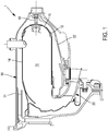
- FIG. figure 6 An injector 100 positioned on a combustion chamber 10 is shown in FIG. figure 6 .
- the injector is placed on the outer annular wall 14 of the combustion chamber and opens into the latter through the opening 109.
- Pre-vaporizing rods 40 are also provided to ignite a greater flow of fuel from the ignited fuel injected. by the injector 100. These pre-vaporization rods are disposed on the bottom wall 16 of the combustion chamber 10.
- the fuel injection circuit 120 is common to both ignition circuits 130 and 140 of the combustion chamber.
- the fuel injection circuit comprises an outlet 121 for supplying the fuel injector 132 of the first ignition circuit 130, and one or more outlets 122 for supplying as much fuel. injectors 142 of the second circuit 140.
- a relief valve 123 closes the fuel outlets 122 for a fuel pressure below a given threshold, for example between 2.5 and 3 bar, so that for such pressure, the fuel flows only to the fuel injector 132.
- the overpressure valve 123 releases the openings 122 to feed the injectors of the second circuit 140.
- the overpressure valve 123 comprises a first channel 125 extending from the fuel supply opening 102 and opening on the one hand towards the outlet 121, and on the other hand on a second channel 126 of diameter more
- the second channel 126 has, at the junction with the first channel 125, a peripheral rim 127.
- a spring 129 whose setting, that is to say the pressure to be exerted to combat the restoring force and compress the spring, corresponds to the aforementioned pressure threshold to release the openings Supply 122 of the injectors of the second circuit 140.
- the ball 128 when the fuel pressure is less than for example 2.5 bar, the ball 128 is in abutment against the flange 127, and its diameter greater than that of the channel 125, it closes the latter. The fuel then flows only to the opening 121. When the fuel pressure increases and exceeds the setting of the spring (between 2.5 and 3 bar), this pressure is sufficient to move the ball 128 and allow the flow fuel to the openings 122.
- the spark plug 101 is ignited, and fuel at a pressure lower than the setting of the spring circulates in the fuel injection circuit.
- the fuel enters the ignition circuit and ignites with the spark plug.
- the fuel pressure increases during a step 220 so that fuel continues to enter the ignition system and be ignited, while fuel is also injected into the second compartment. and ignites in contact with the partition 105. The ignited fuel then enters the combustion chamber.
- the amount of ignited fuel injected into the combustion chamber 10 causes the ignition thereof.
- a step 240 the spark plug as well as the fuel supply are stopped while the combustion chamber is still on.
Landscapes
- Engineering & Computer Science (AREA)
- Chemical & Material Sciences (AREA)
- Combustion & Propulsion (AREA)
- Mechanical Engineering (AREA)
- General Engineering & Computer Science (AREA)
- Ignition Installations For Internal Combustion Engines (AREA)
- Combustion Methods Of Internal-Combustion Engines (AREA)
- Fuel-Injection Apparatus (AREA)
- Pressure-Spray And Ultrasonic-Wave- Spray Burners (AREA)
Priority Applications (1)
| Application Number | Priority Date | Filing Date | Title |
|---|---|---|---|
| PL13779286T PL2904329T3 (pl) | 2012-10-01 | 2013-09-23 | Wtryskiwacz dwuobwodowy do komory spalania maszyny wirowej |
Applications Claiming Priority (2)
| Application Number | Priority Date | Filing Date | Title |
|---|---|---|---|
| FR1259287A FR2996288B1 (fr) | 2012-10-01 | 2012-10-01 | Injecteur a double circuit de chambre de combustion de turbomachine. |
| PCT/FR2013/052205 WO2014053730A2 (fr) | 2012-10-01 | 2013-09-23 | Injecteur a double circuit de chambre de combustion de turbomachine |
Publications (2)
| Publication Number | Publication Date |
|---|---|
| EP2904329A2 EP2904329A2 (fr) | 2015-08-12 |
| EP2904329B1 true EP2904329B1 (fr) | 2019-11-27 |
Family
ID=47425067
Family Applications (1)
| Application Number | Title | Priority Date | Filing Date |
|---|---|---|---|
| EP13779286.7A Active EP2904329B1 (fr) | 2012-10-01 | 2013-09-23 | Injecteur a double circuit de chambre de combustion de turbomachine |
Country Status (10)
| Country | Link |
|---|---|
| US (1) | US9927125B2 (https=) |
| EP (1) | EP2904329B1 (https=) |
| JP (1) | JP6170562B2 (https=) |
| KR (1) | KR102093955B1 (https=) |
| CA (1) | CA2886564C (https=) |
| FR (1) | FR2996288B1 (https=) |
| IN (1) | IN2015DN02445A (https=) |
| PL (1) | PL2904329T3 (https=) |
| RU (1) | RU2632358C2 (https=) |
| WO (1) | WO2014053730A2 (https=) |
Families Citing this family (28)
| Publication number | Priority date | Publication date | Assignee | Title |
|---|---|---|---|---|
| FR2996285B1 (fr) * | 2012-10-01 | 2014-09-12 | Turbomeca | Ensemble de combustion de turbomachine a variation d'alimentation d'air. |
| FR3021073B1 (fr) * | 2014-05-19 | 2019-06-07 | Safran Helicopter Engines | Architecture d'injection de carburant amelioree. |
| FR3028011A1 (fr) * | 2014-10-30 | 2016-05-06 | Turbomeca | Architecture de combustion de carburant adaptee pour le ralenti et le demarrage rapide |
| KR102268593B1 (ko) * | 2016-07-01 | 2021-06-23 | 한화에어로스페이스 주식회사 | 슬링거 연소기 및 이를 구비한 가스 터빈 엔진 시스템 |
| US11519334B2 (en) | 2017-07-31 | 2022-12-06 | General Electric Company | Torch igniter for a combustor |
| US11401867B2 (en) | 2018-09-12 | 2022-08-02 | Pratt & Whitney Canada Corp. | Igniter for gas turbine engine |
| US11268486B2 (en) | 2018-09-12 | 2022-03-08 | Pratt & Whitney Canada Corp. | Igniter for gas turbine engine |
| US11268447B2 (en) | 2018-09-12 | 2022-03-08 | Pratt & Whitney Canada Corp. | Igniter for gas turbine engine |
| US10865761B2 (en) * | 2018-09-12 | 2020-12-15 | Pratt & Whitney Canada Corp | Igniter for gas turbine engine |
| US11391213B2 (en) | 2018-09-12 | 2022-07-19 | Pratt & Whitney Canada Corp. | Igniter for gas turbine engine |
| US11255271B2 (en) | 2018-09-12 | 2022-02-22 | Pratt & Whitney Canada Corp. | Igniter for gas turbine engine |
| US11286861B2 (en) | 2018-09-12 | 2022-03-29 | Pratt & Whitney Canada Corp. | Igniter for gas turbine engine |
| US11408351B2 (en) | 2018-09-12 | 2022-08-09 | Pratt & Whitney Canada Corp. | Igniter for gas turbine engine |
| US11415060B2 (en) | 2018-09-12 | 2022-08-16 | Pratt & Whitney Canada Corp. | Igniter for gas turbine engine |
| US11454173B2 (en) | 2018-09-12 | 2022-09-27 | Pratt & Whitney Canada Corp. | Igniter for gas turbine engine |
| US11391212B2 (en) | 2018-09-12 | 2022-07-19 | Pratt & Whitney Canada Corp. | Igniter for gas turbine engine |
| US11473505B2 (en) | 2020-11-04 | 2022-10-18 | Delavan Inc. | Torch igniter cooling system |
| US11692488B2 (en) * | 2020-11-04 | 2023-07-04 | Delavan Inc. | Torch igniter cooling system |
| US11608783B2 (en) | 2020-11-04 | 2023-03-21 | Delavan, Inc. | Surface igniter cooling system |
| US11635027B2 (en) | 2020-11-18 | 2023-04-25 | Collins Engine Nozzles, Inc. | Fuel systems for torch ignition devices |
| US11421602B2 (en) | 2020-12-16 | 2022-08-23 | Delavan Inc. | Continuous ignition device exhaust manifold |
| US11635210B2 (en) | 2020-12-17 | 2023-04-25 | Collins Engine Nozzles, Inc. | Conformal and flexible woven heat shields for gas turbine engine components |
| US11754289B2 (en) | 2020-12-17 | 2023-09-12 | Delavan, Inc. | Axially oriented internally mounted continuous ignition device: removable nozzle |
| US11486309B2 (en) | 2020-12-17 | 2022-11-01 | Delavan Inc. | Axially oriented internally mounted continuous ignition device: removable hot surface igniter |
| US12092333B2 (en) | 2020-12-17 | 2024-09-17 | Collins Engine Nozzles, Inc. | Radially oriented internally mounted continuous ignition device |
| US11680528B2 (en) * | 2020-12-18 | 2023-06-20 | Delavan Inc. | Internally-mounted torch igniters with removable igniter heads |
| US11209164B1 (en) * | 2020-12-18 | 2021-12-28 | Delavan Inc. | Fuel injector systems for torch igniters |
| KR102584126B1 (ko) * | 2021-11-01 | 2023-09-27 | 한국항공우주연구원 | 가스터빈용 슬링거 연소기 |
Citations (2)
| Publication number | Priority date | Publication date | Assignee | Title |
|---|---|---|---|---|
| US2693082A (en) * | 1951-04-04 | 1954-11-02 | Gen Motors Corp | Gas turbine fuel igniter |
| GB914906A (en) * | 1958-12-10 | 1963-01-09 | Snecma | Burner for hot fuel |
Family Cites Families (16)
| Publication number | Priority date | Publication date | Assignee | Title |
|---|---|---|---|---|
| CH288548A (fr) * | 1948-12-24 | 1953-01-31 | Canadian Patents Dev | Chambre de combustion pour turbine à gaz. |
| BE525083A (https=) * | 1952-12-20 | |||
| US2972231A (en) * | 1954-09-23 | 1961-02-21 | Ii James W Mullen | Rod-igniters for ramjet burners |
| US2949012A (en) * | 1957-03-01 | 1960-08-16 | Snecma | Vaporisation burner device |
| US4121419A (en) * | 1977-01-26 | 1978-10-24 | Kuznetsov Vladimir Grigorievic | Start flame igniter of the combustion chamber of a gas-turbine engine |
| DE3728712A1 (de) * | 1987-08-28 | 1989-03-09 | Webasto Ag Fahrzeugtechnik | Brenner fuer schwer-zuendliche gemische |
| US5167122A (en) * | 1991-04-30 | 1992-12-01 | Sundstrand Corporation | Fuel system for a turbo machine |
| RU2083858C1 (ru) * | 1993-03-02 | 1997-07-10 | Омское моторостроительное конструкторское бюро | Воспламенитель камеры сгорания газотурбинного двигателя |
| EP0992661B1 (de) * | 1998-10-05 | 2003-12-03 | ALSTOM (Switzerland) Ltd | Zündbrenner für eine Brennkammer |
| DE10112864A1 (de) * | 2001-03-16 | 2002-09-19 | Alstom Switzerland Ltd | Verfahren zum Zünden einer thermischen Turbomaschine |
| DE10211141A1 (de) * | 2002-03-14 | 2003-09-25 | Alstom Switzerland Ltd | Verfahren zum Zünden der Brennkammer einer Gasturbinenanlage sowie Zündvorrichtung zur Durchführung des Verfahrens |
| JP3990678B2 (ja) * | 2004-03-17 | 2007-10-17 | 川崎重工業株式会社 | ガスタービン燃焼器 |
| GB2444737B (en) * | 2006-12-13 | 2009-03-04 | Siemens Ag | Improvements in or relating to burners for a gas turbine engine |
| FR2971039B1 (fr) | 2011-02-02 | 2013-01-11 | Turbomeca | Injecteur de chambre de combustion de turbine a gaz a double circuit de carburant et chambre de combustion equipee d'au moins un tel injecteur |
| EP2743588A1 (en) * | 2012-12-11 | 2014-06-18 | Siemens Aktiengesellschaft | Recessed fuel injector positioning |
| US9080772B2 (en) * | 2013-06-13 | 2015-07-14 | Delavan Inc | Continuous ignition |
-
2012
- 2012-10-01 FR FR1259287A patent/FR2996288B1/fr active Active
-
2013
- 2013-09-23 RU RU2015116648A patent/RU2632358C2/ru active
- 2013-09-23 JP JP2015533668A patent/JP6170562B2/ja not_active Expired - Fee Related
- 2013-09-23 CA CA2886564A patent/CA2886564C/fr active Active
- 2013-09-23 WO PCT/FR2013/052205 patent/WO2014053730A2/fr not_active Ceased
- 2013-09-23 US US14/432,952 patent/US9927125B2/en active Active
- 2013-09-23 EP EP13779286.7A patent/EP2904329B1/fr active Active
- 2013-09-23 KR KR1020157011576A patent/KR102093955B1/ko not_active Expired - Fee Related
- 2013-09-23 PL PL13779286T patent/PL2904329T3/pl unknown
-
2015
- 2015-03-25 IN IN2445DEN2015 patent/IN2015DN02445A/en unknown
Patent Citations (2)
| Publication number | Priority date | Publication date | Assignee | Title |
|---|---|---|---|---|
| US2693082A (en) * | 1951-04-04 | 1954-11-02 | Gen Motors Corp | Gas turbine fuel igniter |
| GB914906A (en) * | 1958-12-10 | 1963-01-09 | Snecma | Burner for hot fuel |
Also Published As
| Publication number | Publication date |
|---|---|
| CN104704294A (zh) | 2015-06-10 |
| WO2014053730A2 (fr) | 2014-04-10 |
| PL2904329T3 (pl) | 2020-09-07 |
| WO2014053730A3 (fr) | 2014-07-17 |
| FR2996288B1 (fr) | 2014-09-12 |
| JP2015531448A (ja) | 2015-11-02 |
| CA2886564A1 (fr) | 2014-04-10 |
| US9927125B2 (en) | 2018-03-27 |
| KR102093955B1 (ko) | 2020-03-27 |
| EP2904329A2 (fr) | 2015-08-12 |
| US20150260406A1 (en) | 2015-09-17 |
| FR2996288A1 (fr) | 2014-04-04 |
| RU2015116648A (ru) | 2016-11-27 |
| JP6170562B2 (ja) | 2017-07-26 |
| CA2886564C (fr) | 2020-06-02 |
| IN2015DN02445A (https=) | 2015-09-04 |
| KR20150063549A (ko) | 2015-06-09 |
| RU2632358C2 (ru) | 2017-10-04 |
Similar Documents
| Publication | Publication Date | Title |
|---|---|---|
| EP2904329B1 (fr) | Injecteur a double circuit de chambre de combustion de turbomachine | |
| EP1965056B1 (fr) | Procédé pour le démarrage d'un moteur d'hélicoptère à turbine à gaz, circuit d'alimentation en carburant d'un tel moteur, et moteur ayant un tel circuit | |
| EP2951421B1 (fr) | Ensemble de combustion de turbomachine comprenant un circuit d'alimentation de carburant amélioré | |
| CA2639980C (fr) | Chambre de combustion d'une turbomachine | |
| FR3042543A1 (fr) | Torche d'allumage pour moteur fusee | |
| EP2904324B1 (fr) | Ensemble de combustion de turbomachine a variation d'alimentation d'air | |
| EP3147490B1 (fr) | Système de propulsion d'une fusée | |
| FR3001525A1 (fr) | Procede de gestion de la consommation de carburant d un ensemble bimoteur et ensemble associe | |
| FR2769046A1 (fr) | Procede de mise en oeuvre d'un moteur a combustion interne et systeme d'injection de carburant pour la mise en oeuvre du procede | |
| FR2496164A1 (fr) | Moteur a combustion interne suralimente par turbocompresseurs a gaz d'echappement | |
| EP2591288B1 (fr) | Procédure d'allumage pour une chambre de combustion de turbomachine | |
| WO2017006063A1 (fr) | Chambre de combustion coudée d'une turbomachine | |
| FR3039220A1 (fr) | Dipositif de postcombustion pour turboreacteur | |
| FR3027059B1 (fr) | Systeme d'allumage d'une chambre de combustion d'un turbomoteur | |
| FR3114614A1 (fr) | Dispositif d’allumage à préchambre pour moteur à combustion interne à allumage commandé | |
| FR3022986B1 (fr) | Procede d'allumage d'une chambre de combustion de turbomachine | |
| EP3569858B1 (fr) | Moteur fusée solide-hybride amélioré | |
| FR3028011A1 (fr) | Architecture de combustion de carburant adaptee pour le ralenti et le demarrage rapide | |
| FR3095006A1 (fr) | Injecteur de carburant a element chauffant integre pour une turbine a gaz et son procede de fabrication | |
| BE353842A (https=) | ||
| FR2927664A1 (fr) | Procede de pilotage au demarrage d'un injecteur de carburant et moteur a combustion interne apte a mettre en oeuvre ce procede | |
| EP2740635A1 (fr) | Générateur de gaz | |
| BE390344A (https=) |
Legal Events
| Date | Code | Title | Description |
|---|---|---|---|
| PUAI | Public reference made under article 153(3) epc to a published international application that has entered the european phase |
Free format text: ORIGINAL CODE: 0009012 |
|
| 17P | Request for examination filed |
Effective date: 20150427 |
|
| AK | Designated contracting states |
Kind code of ref document: A2 Designated state(s): AL AT BE BG CH CY CZ DE DK EE ES FI FR GB GR HR HU IE IS IT LI LT LU LV MC MK MT NL NO PL PT RO RS SE SI SK SM TR |
|
| AX | Request for extension of the european patent |
Extension state: BA ME |
|
| DAX | Request for extension of the european patent (deleted) | ||
| RAP1 | Party data changed (applicant data changed or rights of an application transferred) |
Owner name: SAFRAN HELICOPTER ENGINES |
|
| STAA | Information on the status of an ep patent application or granted ep patent |
Free format text: STATUS: EXAMINATION IS IN PROGRESS |
|
| 17Q | First examination report despatched |
Effective date: 20180622 |
|
| GRAP | Despatch of communication of intention to grant a patent |
Free format text: ORIGINAL CODE: EPIDOSNIGR1 |
|
| STAA | Information on the status of an ep patent application or granted ep patent |
Free format text: STATUS: GRANT OF PATENT IS INTENDED |
|
| INTG | Intention to grant announced |
Effective date: 20190606 |
|
| GRAS | Grant fee paid |
Free format text: ORIGINAL CODE: EPIDOSNIGR3 |
|
| GRAA | (expected) grant |
Free format text: ORIGINAL CODE: 0009210 |
|
| STAA | Information on the status of an ep patent application or granted ep patent |
Free format text: STATUS: THE PATENT HAS BEEN GRANTED |
|
| AK | Designated contracting states |
Kind code of ref document: B1 Designated state(s): AL AT BE BG CH CY CZ DE DK EE ES FI FR GB GR HR HU IE IS IT LI LT LU LV MC MK MT NL NO PL PT RO RS SE SI SK SM TR |
|
| REG | Reference to a national code |
Ref country code: GB Ref legal event code: FG4D Free format text: NOT ENGLISH |
|
| REG | Reference to a national code |
Ref country code: CH Ref legal event code: EP |
|
| REG | Reference to a national code |
Ref country code: AT Ref legal event code: REF Ref document number: 1207097 Country of ref document: AT Kind code of ref document: T Effective date: 20191215 |
|
| REG | Reference to a national code |
Ref country code: DE Ref legal event code: R096 Ref document number: 602013063392 Country of ref document: DE |
|
| REG | Reference to a national code |
Ref country code: IE Ref legal event code: FG4D Free format text: LANGUAGE OF EP DOCUMENT: FRENCH |
|
| REG | Reference to a national code |
Ref country code: NL Ref legal event code: MP Effective date: 20191127 |
|
| REG | Reference to a national code |
Ref country code: LT Ref legal event code: MG4D |
|
| PG25 | Lapsed in a contracting state [announced via postgrant information from national office to epo] |
Ref country code: LV Free format text: LAPSE BECAUSE OF FAILURE TO SUBMIT A TRANSLATION OF THE DESCRIPTION OR TO PAY THE FEE WITHIN THE PRESCRIBED TIME-LIMIT Effective date: 20191127 Ref country code: BG Free format text: LAPSE BECAUSE OF FAILURE TO SUBMIT A TRANSLATION OF THE DESCRIPTION OR TO PAY THE FEE WITHIN THE PRESCRIBED TIME-LIMIT Effective date: 20200227 Ref country code: SE Free format text: LAPSE BECAUSE OF FAILURE TO SUBMIT A TRANSLATION OF THE DESCRIPTION OR TO PAY THE FEE WITHIN THE PRESCRIBED TIME-LIMIT Effective date: 20191127 Ref country code: FI Free format text: LAPSE BECAUSE OF FAILURE TO SUBMIT A TRANSLATION OF THE DESCRIPTION OR TO PAY THE FEE WITHIN THE PRESCRIBED TIME-LIMIT Effective date: 20191127 Ref country code: GR Free format text: LAPSE BECAUSE OF FAILURE TO SUBMIT A TRANSLATION OF THE DESCRIPTION OR TO PAY THE FEE WITHIN THE PRESCRIBED TIME-LIMIT Effective date: 20200228 Ref country code: NO Free format text: LAPSE BECAUSE OF FAILURE TO SUBMIT A TRANSLATION OF THE DESCRIPTION OR TO PAY THE FEE WITHIN THE PRESCRIBED TIME-LIMIT Effective date: 20200227 Ref country code: LT Free format text: LAPSE BECAUSE OF FAILURE TO SUBMIT A TRANSLATION OF THE DESCRIPTION OR TO PAY THE FEE WITHIN THE PRESCRIBED TIME-LIMIT Effective date: 20191127 Ref country code: NL Free format text: LAPSE BECAUSE OF FAILURE TO SUBMIT A TRANSLATION OF THE DESCRIPTION OR TO PAY THE FEE WITHIN THE PRESCRIBED TIME-LIMIT Effective date: 20191127 |
|
| PG25 | Lapsed in a contracting state [announced via postgrant information from national office to epo] |
Ref country code: HR Free format text: LAPSE BECAUSE OF FAILURE TO SUBMIT A TRANSLATION OF THE DESCRIPTION OR TO PAY THE FEE WITHIN THE PRESCRIBED TIME-LIMIT Effective date: 20191127 Ref country code: IS Free format text: LAPSE BECAUSE OF FAILURE TO SUBMIT A TRANSLATION OF THE DESCRIPTION OR TO PAY THE FEE WITHIN THE PRESCRIBED TIME-LIMIT Effective date: 20200327 Ref country code: RS Free format text: LAPSE BECAUSE OF FAILURE TO SUBMIT A TRANSLATION OF THE DESCRIPTION OR TO PAY THE FEE WITHIN THE PRESCRIBED TIME-LIMIT Effective date: 20191127 |
|
| PG25 | Lapsed in a contracting state [announced via postgrant information from national office to epo] |
Ref country code: AL Free format text: LAPSE BECAUSE OF FAILURE TO SUBMIT A TRANSLATION OF THE DESCRIPTION OR TO PAY THE FEE WITHIN THE PRESCRIBED TIME-LIMIT Effective date: 20191127 |
|
| PG25 | Lapsed in a contracting state [announced via postgrant information from national office to epo] |
Ref country code: RO Free format text: LAPSE BECAUSE OF FAILURE TO SUBMIT A TRANSLATION OF THE DESCRIPTION OR TO PAY THE FEE WITHIN THE PRESCRIBED TIME-LIMIT Effective date: 20191127 Ref country code: EE Free format text: LAPSE BECAUSE OF FAILURE TO SUBMIT A TRANSLATION OF THE DESCRIPTION OR TO PAY THE FEE WITHIN THE PRESCRIBED TIME-LIMIT Effective date: 20191127 Ref country code: PT Free format text: LAPSE BECAUSE OF FAILURE TO SUBMIT A TRANSLATION OF THE DESCRIPTION OR TO PAY THE FEE WITHIN THE PRESCRIBED TIME-LIMIT Effective date: 20200419 Ref country code: ES Free format text: LAPSE BECAUSE OF FAILURE TO SUBMIT A TRANSLATION OF THE DESCRIPTION OR TO PAY THE FEE WITHIN THE PRESCRIBED TIME-LIMIT Effective date: 20191127 Ref country code: DK Free format text: LAPSE BECAUSE OF FAILURE TO SUBMIT A TRANSLATION OF THE DESCRIPTION OR TO PAY THE FEE WITHIN THE PRESCRIBED TIME-LIMIT Effective date: 20191127 |
|
| REG | Reference to a national code |
Ref country code: DE Ref legal event code: R097 Ref document number: 602013063392 Country of ref document: DE |
|
| PG25 | Lapsed in a contracting state [announced via postgrant information from national office to epo] |
Ref country code: SM Free format text: LAPSE BECAUSE OF FAILURE TO SUBMIT A TRANSLATION OF THE DESCRIPTION OR TO PAY THE FEE WITHIN THE PRESCRIBED TIME-LIMIT Effective date: 20191127 Ref country code: SK Free format text: LAPSE BECAUSE OF FAILURE TO SUBMIT A TRANSLATION OF THE DESCRIPTION OR TO PAY THE FEE WITHIN THE PRESCRIBED TIME-LIMIT Effective date: 20191127 |
|
| REG | Reference to a national code |
Ref country code: AT Ref legal event code: MK05 Ref document number: 1207097 Country of ref document: AT Kind code of ref document: T Effective date: 20191127 |
|
| PLBE | No opposition filed within time limit |
Free format text: ORIGINAL CODE: 0009261 |
|
| STAA | Information on the status of an ep patent application or granted ep patent |
Free format text: STATUS: NO OPPOSITION FILED WITHIN TIME LIMIT |
|
| 26N | No opposition filed |
Effective date: 20200828 |
|
| PG25 | Lapsed in a contracting state [announced via postgrant information from national office to epo] |
Ref country code: AT Free format text: LAPSE BECAUSE OF FAILURE TO SUBMIT A TRANSLATION OF THE DESCRIPTION OR TO PAY THE FEE WITHIN THE PRESCRIBED TIME-LIMIT Effective date: 20191127 Ref country code: SI Free format text: LAPSE BECAUSE OF FAILURE TO SUBMIT A TRANSLATION OF THE DESCRIPTION OR TO PAY THE FEE WITHIN THE PRESCRIBED TIME-LIMIT Effective date: 20191127 |
|
| PG25 | Lapsed in a contracting state [announced via postgrant information from national office to epo] |
Ref country code: IT Free format text: LAPSE BECAUSE OF FAILURE TO SUBMIT A TRANSLATION OF THE DESCRIPTION OR TO PAY THE FEE WITHIN THE PRESCRIBED TIME-LIMIT Effective date: 20191127 |
|
| PG25 | Lapsed in a contracting state [announced via postgrant information from national office to epo] |
Ref country code: MC Free format text: LAPSE BECAUSE OF FAILURE TO SUBMIT A TRANSLATION OF THE DESCRIPTION OR TO PAY THE FEE WITHIN THE PRESCRIBED TIME-LIMIT Effective date: 20191127 |
|
| REG | Reference to a national code |
Ref country code: CH Ref legal event code: PL |
|
| REG | Reference to a national code |
Ref country code: BE Ref legal event code: MM Effective date: 20200930 |
|
| PG25 | Lapsed in a contracting state [announced via postgrant information from national office to epo] |
Ref country code: LU Free format text: LAPSE BECAUSE OF NON-PAYMENT OF DUE FEES Effective date: 20200923 |
|
| PG25 | Lapsed in a contracting state [announced via postgrant information from national office to epo] |
Ref country code: CH Free format text: LAPSE BECAUSE OF NON-PAYMENT OF DUE FEES Effective date: 20200930 Ref country code: BE Free format text: LAPSE BECAUSE OF NON-PAYMENT OF DUE FEES Effective date: 20200930 Ref country code: IE Free format text: LAPSE BECAUSE OF NON-PAYMENT OF DUE FEES Effective date: 20200923 Ref country code: LI Free format text: LAPSE BECAUSE OF NON-PAYMENT OF DUE FEES Effective date: 20200930 |
|
| PG25 | Lapsed in a contracting state [announced via postgrant information from national office to epo] |
Ref country code: TR Free format text: LAPSE BECAUSE OF FAILURE TO SUBMIT A TRANSLATION OF THE DESCRIPTION OR TO PAY THE FEE WITHIN THE PRESCRIBED TIME-LIMIT Effective date: 20191127 Ref country code: MT Free format text: LAPSE BECAUSE OF FAILURE TO SUBMIT A TRANSLATION OF THE DESCRIPTION OR TO PAY THE FEE WITHIN THE PRESCRIBED TIME-LIMIT Effective date: 20191127 Ref country code: CY Free format text: LAPSE BECAUSE OF FAILURE TO SUBMIT A TRANSLATION OF THE DESCRIPTION OR TO PAY THE FEE WITHIN THE PRESCRIBED TIME-LIMIT Effective date: 20191127 |
|
| PG25 | Lapsed in a contracting state [announced via postgrant information from national office to epo] |
Ref country code: MK Free format text: LAPSE BECAUSE OF FAILURE TO SUBMIT A TRANSLATION OF THE DESCRIPTION OR TO PAY THE FEE WITHIN THE PRESCRIBED TIME-LIMIT Effective date: 20191127 |
|
| PGFP | Annual fee paid to national office [announced via postgrant information from national office to epo] |
Ref country code: GB Payment date: 20220818 Year of fee payment: 10 Ref country code: DE Payment date: 20220616 Year of fee payment: 10 Ref country code: CZ Payment date: 20220824 Year of fee payment: 10 |
|
| PGFP | Annual fee paid to national office [announced via postgrant information from national office to epo] |
Ref country code: PL Payment date: 20220822 Year of fee payment: 10 |
|
| REG | Reference to a national code |
Ref country code: DE Ref legal event code: R119 Ref document number: 602013063392 Country of ref document: DE |
|
| PG25 | Lapsed in a contracting state [announced via postgrant information from national office to epo] |
Ref country code: CZ Free format text: LAPSE BECAUSE OF NON-PAYMENT OF DUE FEES Effective date: 20230923 |
|
| GBPC | Gb: european patent ceased through non-payment of renewal fee |
Effective date: 20230923 |
|
| PG25 | Lapsed in a contracting state [announced via postgrant information from national office to epo] |
Ref country code: GB Free format text: LAPSE BECAUSE OF NON-PAYMENT OF DUE FEES Effective date: 20230923 |
|
| PG25 | Lapsed in a contracting state [announced via postgrant information from national office to epo] |
Ref country code: GB Free format text: LAPSE BECAUSE OF NON-PAYMENT OF DUE FEES Effective date: 20230923 Ref country code: DE Free format text: LAPSE BECAUSE OF NON-PAYMENT OF DUE FEES Effective date: 20240403 |
|
| PG25 | Lapsed in a contracting state [announced via postgrant information from national office to epo] |
Ref country code: PL Free format text: LAPSE BECAUSE OF NON-PAYMENT OF DUE FEES Effective date: 20230923 |
|
| PGFP | Annual fee paid to national office [announced via postgrant information from national office to epo] |
Ref country code: FR Payment date: 20250923 Year of fee payment: 13 |