EP2903808B1 - Vorrichtung zur herstellung einer lauffläche eines reifenrohlings - Google Patents
Vorrichtung zur herstellung einer lauffläche eines reifenrohlings Download PDFInfo
- Publication number
- EP2903808B1 EP2903808B1 EP13782807.5A EP13782807A EP2903808B1 EP 2903808 B1 EP2903808 B1 EP 2903808B1 EP 13782807 A EP13782807 A EP 13782807A EP 2903808 B1 EP2903808 B1 EP 2903808B1
- Authority
- EP
- European Patent Office
- Prior art keywords
- wall
- diameter
- support
- axis
- drum
- Prior art date
- Legal status (The legal status is an assumption and is not a legal conclusion. Google has not performed a legal analysis and makes no representation as to the accuracy of the status listed.)
- Active
Links
Images

Classifications
-
- B—PERFORMING OPERATIONS; TRANSPORTING
- B60—VEHICLES IN GENERAL
- B60C—VEHICLE TYRES; TYRE INFLATION; TYRE CHANGING; CONNECTING VALVES TO INFLATABLE ELASTIC BODIES IN GENERAL; DEVICES OR ARRANGEMENTS RELATED TO TYRES
- B60C9/00—Reinforcements or ply arrangement of pneumatic tyres
- B60C9/02—Carcasses
- B60C9/023—Carcasses built up from narrow strips, individual cords or filaments, e.g. using filament winding
-
- B—PERFORMING OPERATIONS; TRANSPORTING
- B29—WORKING OF PLASTICS; WORKING OF SUBSTANCES IN A PLASTIC STATE IN GENERAL
- B29D—PRODUCING PARTICULAR ARTICLES FROM PLASTICS OR FROM SUBSTANCES IN A PLASTIC STATE
- B29D30/00—Producing pneumatic or solid tyres or parts thereof
- B29D30/06—Pneumatic tyres or parts thereof (e.g. produced by casting, moulding, compression moulding, injection moulding, centrifugal casting)
- B29D30/08—Building tyres
- B29D30/20—Building tyres by the flat-tyre method, i.e. building on cylindrical drums
- B29D30/24—Drums
- B29D30/242—Drums for manufacturing substantially cylindrical tyre components without cores or beads, e.g. treads or belts
-
- B—PERFORMING OPERATIONS; TRANSPORTING
- B29—WORKING OF PLASTICS; WORKING OF SUBSTANCES IN A PLASTIC STATE IN GENERAL
- B29D—PRODUCING PARTICULAR ARTICLES FROM PLASTICS OR FROM SUBSTANCES IN A PLASTIC STATE
- B29D30/00—Producing pneumatic or solid tyres or parts thereof
- B29D30/06—Pneumatic tyres or parts thereof (e.g. produced by casting, moulding, compression moulding, injection moulding, centrifugal casting)
- B29D30/08—Building tyres
- B29D30/20—Building tyres by the flat-tyre method, i.e. building on cylindrical drums
- B29D30/24—Drums
-
- B—PERFORMING OPERATIONS; TRANSPORTING
- B29—WORKING OF PLASTICS; WORKING OF SUBSTANCES IN A PLASTIC STATE IN GENERAL
- B29K—INDEXING SCHEME ASSOCIATED WITH SUBCLASSES B29B, B29C OR B29D, RELATING TO MOULDING MATERIALS OR TO MATERIALS FOR MOULDS, REINFORCEMENTS, FILLERS OR PREFORMED PARTS, e.g. INSERTS
- B29K2021/00—Use of unspecified rubbers as moulding material
Definitions
- the invention relates to devices for manufacturing treads for tire casings.
- a cylindrical component forming part of a tire blank such as for example a tread for a tire casing
- the winding is carried out over several tens of turns and at high speed.
- the dispensing means of the strip relative to said drum are displaced in the axial direction of the drum in order to accumulate the strip at the desired locations and to give its general shape to the tread.
- the outer face of the drum on which the rubber elements are arranged must present as much as possible a perfectly circular cross section.
- this face must have no relief or cavity likely to damage it.
- variable diameter drums consisting of cylinder elements of a given diameter which seek to achieve it but they are not satisfactory, in that when the drum is brought to a diameter greater than or less than the diameter of the elements which the make up the section of the drum is no longer a perfectly circular section
- US 4923554 - A and US 3932256 - A discloses variable diameter tire building drums, the drums comprising circumferentially arranged sectors, each sector being provided with a cover plate to secure an outer face of a generally circular shape.
- the document US 2011/0303366 - A discloses a variable diameter tire building drum, the drum comprising multi-section segments which are radially movable with respect to the central axis and which include arcuate surfaces which collectively define the circumference of the drum.
- Each segment includes a primary section and a secondary section that flanks the primary section.
- the primary and secondary sections are connected so that when the segments are moved radially, the primary and secondary sections move relative to each other along the circumference of the apparatus to maintain uniformity , or the roundness, of the surface of the circumference.
- the document US 4929298 - A discloses a tire-making drum of variable diameter, the drum comprising circumferentially arranged segments.
- the segments are covered by a continuous elastic bushing, to ensure an outer face of a generally circular shape.
- the document US 4060445 - A discloses a drum of variable diameter tire construction, the drum being covered by a continuous elastic sleeve, to ensure an outer face of a generally circular shape.
- An object of the invention is to provide a garment drum having a face external whose section has a generally circular shape and whose diameter is variable.
- this wall has an outer face whose general shape approaches particularly well that of a cylinder of circular section. And whatever the diameter chosen, we can arrange the turns of the wall edge to edge, so that this face has no significant relief or cavity likely to damage the rubber.
- the wall forms a spring.
- This feature facilitates the change of wall diameter.
- the stiffness of the spring tends to standardize the general shape of the wall so that it spontaneously approaches that of a cylinder.
- the device is arranged so that, in the configuration of the adjustment means giving the wall its smallest diameter, the wall has a minimum external diameter on the device greater than an external diameter that it has at rest out of the device. .
- the wall is made of aluminum.
- this metal in such a context has many advantages. First, it is lightweight compared to other metals, which decreases the weight of the wall. However, it is supported with a large part of the device cantilevered by a frame. This reduction in weight is therefore advantageous for the dimensioning of the device.
- the drum being rotated during manufacture the low mass of aluminum reduces the moment of inertia of the rotating assembly. In return, this lightness makes it possible to give the wall a relatively large thickness so that its turns remain in contact against each other without overlapping. And with such a thickness, aluminum does not give too much stiffness to the wall, which facilitates changes in diameter.
- aluminum allows large diameter changes, for example in a ratio of two between the two extreme values.
- aluminum offers good thermal conductivity. Now the rubber strip is rolled up at high speed and is initially very hot. It is therefore important that it can reach the ambient temperature as quickly as possible. The thermal conductivity of aluminum makes it easier.
- the device comprises a support, the wall having a first end immobilized against its translation relative to the support and a second free end movable in translation relative to the support.
- the first end is hinged to the support.
- the support comprises a pin adapted to bear against different zones of a turn of the wall contiguous to the first end, in a configuration taken by the wall.
- This pin makes it possible to precisely define the position of the first turn regardless of the chosen diameter. It does not prohibit the above pivoting but limits the amplitude to give the wall faster its cylindrical shape.
- the support comprises spacers bearing the wall and movably mounted relative to an axis of the device in a direction radial to the axis.
- the device comprises rods carrying each spacer.
- the wall immobilizes the spacers by friction against their distance from the axis.
- This immobilization increases the stiffness of the drum during winding. It also increases the stability of the wall.
- the device comprises at least one member capable of separating the wall and the support under the effect of vibrations produced by said member.
- frictional immobilization can be easily interrupted when it is desired to modify the diameter of the wall.
- the device comprises at least one flange adapted to maintain turns of the wall in contact with each other in an axial direction of the wall.
- This flange makes it possible to preserve the continuity of the external face of the wall in the axial direction.
- the device comprises at least one flange adapted to retain a free end turn of the wall against its distance from a wall axis.
- This flange avoids inadvertent detachment of the free end turn. This maintenance is sufficient to prevent the detachment of all other turns.
- each retaining flange is formed by the flange or one of the holding flanges.
- the flange or at least one of the flanges is mounted movably by relative to the wall in an axial direction of the wall.
- the device comprises at least one actuator adapted to move the or each flange relative to the wall in an axial direction of the wall.
- the device comprises a fan adapted to circulate air in a chamber defined by the wall.
- This fan facilitates the cooling of the device and the rubber wound on it.
- the device comprises arms capable of bearing against an outer face of the wall
- arms can have different uses. It is thus possible to put the greater part of the wall in uniform support against the arms all around the axis to facilitate the change of diameter and in particular the change of configuration of the support in contact with the inner face of the wall.
- the arms thus ensure the maintenance of the wall while increasing the diameter of the support intended to support it.
- the arms can be placed in uniform abutment against a tread blank carried by the wall. We can then reduce the diameter of the latter and extract the blank wall. This maintenance of the draft preserves its shape and integrity.
- the device is arranged so that the arms can be moved radially to an axis of the wall simultaneously.
- the device comprises a member adapted to attach to one of the arms a free end turn of the wall.
- each arm carries rollers adapted to come into contact with the wall.
- rollers make it possible to roll the wall against the support once the latter has been placed in the configuration corresponding to the desired diameter for the wall.
- the rollers of each arm are movably mounted between a position in which they project from the arm towards the axis and a position in which they do not extend projecting from the arm in the direction of the axis. of the axis.
- the arms being applied against a tread blank carried by the wall, a diameter of the wall is reduced.
- the tube is manufactured by rolling or forging.
- the wall is machined to reduce its thickness.
- the wall is made of aluminum, for example T6-treated 7075 aluminum.
- a method of manufacturing a device for producing a tread of a tire casing in which a method as mentioned above is implemented and the wall is mounted on means for adjusting a tire. diameter of the wall so that the wall has, in the configuration of the adjustment means giving it its smallest diameter, a minimum external diameter greater than its outer diameter at rest out of the device.
- a device for producing a tread of a tire envelope which comprises a helical outer wall and means for adjusting a diameter of the wall, the device being arranged so that the wall has, in the configuration of the adjustment means giving it its smallest diameter, a minimum external diameter greater than its external diameter at rest out of the device .
- Figures 1 to 17 a device according to the invention for manufacturing a tread of a tire blank of a vehicle tire.
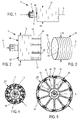
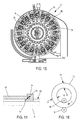
- the drum 4 has a generally symmetrical shape of revolution of horizontal axis 6. It comprises a hub 8 through which the drum is rotatably mounted relative to a frame, not shown, of the device, the axis of rotation being axis 6.
- the drum comprises an outer wall 10, illustrated in particular in Figures 1 to 3 .
- This wall has a generally cylindrical shape of axis 6 and a circular section in a plane perpendicular to the axis.
- This wall is made of metal, and in this case aluminum. This is aluminum called 7075 and treated T6.
- a tube 12 is produced having outer cylindrical walls 14 and inner 16 circular section in a plane perpendicular to the axis of the tube.
- the tube is manufactured by rolling as shown in FIG. figure 17 or by forging.
- the tube is circulated between two rolling rolls 18 respectively against its inner and outer faces. During this rolling, the thickness e of the tube decreases until the desired value.
- Rolling has the advantage of increasing the strength of the workpiece and orienting the crystals in the right direction.
- the tube is thermally treated by quenching at 475 ° C. for 5 hours and then at 135 ° C. for 13 hours, these values being given by way of non-limiting example only.
- machining is resumed of this blank to further thin the thickness of the tube to reach the thickness of the final part.
- a cut is made of the wall of the tube passing through the entire thickness of the latter and going from one to the other of its axial ends.
- the cut has a helical shape and thus defines successive turns. It is performed with a tool oriented radially to the axis so that the turns have straight edges.
- This method of manufacture in particular the machining in the mass, makes it possible to obtain a part without residual internal stress and which has a good working ability on opening, that is to say to the enlargement of its diameter. .
- the drum 4 comprises spacers or sectors 20, having a generally elongated shape in a direction parallel to the axis 6, identical to each other, and regularly spaced around the axis 6.
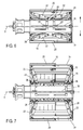
- Each spacer 20 is connected to the hub by two links 22 visible in particular to Figures 6 and 7 .
- Each of these rods has an end articulated directly to a respective end of the spacer about an axis 24 perpendicular to the axis 6 and parallel to the circumferential direction to this axis.
- the drum 4 comprises two rings 26 to which are articulated the other respective ends of the two rods.
- the two rings 26 are movably mounted to slide on the hub 8 in the direction of the axis 6.
- Each rod 22 is associated with a rod 28 articulated on the one hand in the middle part of the rod 22, and secondly directly at the hub 4 without the possibility of sliding of this articulation relative to the hub along the axis 6.
- the hub further comprises an axial screw 30 having two threads 29 oriented in opposite directions, and with which are threaded rings 26.
- the screw is rotatably mounted relative to the hub and slidably fixed relative thereto.
- the device comprises motorization means, not shown, the rotation of the screw.
- the spacers 20 can only move simultaneously in the radial direction to move away from the axis or closer. At all times, the spacers all extend radially at the same distance from the axis.
- the spacers 20 has been illustrated in detail at figure 8 . It comprises a support element 32 and a reserve element 34 which follow one another in a direction parallel to the axis 6.
- the support element 32 has a generally profiled shape with a "V" profile in the direction of the 'axis. The ends of the branches of the "V” are oriented in the opposite direction to the axis.
- the reserve element 34 has two faces 38, 39 of generally rectangular shape giving it a generally shaped profile with a "V” profile but the branches are this time oriented in the direction of the axis.
- the support member 32 thus provides two edges 36 for supporting the wall 10, the latter spanning the space defined between these two edges.
- the reserve element 34 offers the two faces 38, 39.
- the wall 10 rests mainly on the support elements 32 without covering the majority of the reserve elements 34. These therefore form, just like the wall 10, a portion of the outer face of the drum.
- the wall 10 covers all the support elements and reserve elements so that none of these is no longer visible. The decrease in the diameter of the wall is therefore compensated by an increase in its length along the axial direction.
- the end 40 of the helical wall 10 which is closest to the frame that is to say the one on the left on the Figures 1 and 2 , is articulated to the corresponding end of one of the spacers so as to prohibit any movement of this end in any direction relative to the spacer except its rotation about an axis 42 radial to the axis 6.
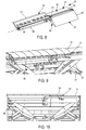
- Another of the spacers carries at its homologous end a pin 46 projecting radially from the spacer so that an outer edge 48 of the first turn can bear against the pin.
- This edge has two sections that follow one another along the turn and each have a rectilinear shape.
- the section 48, closest to the end of the turn, is perpendicular to the axis 6 when the wall is at its smallest diameter.
- the other section 50 is inclined with respect to the previous one and with respect to the axis 6.
- the pin is arranged so that, in the smaller diameter configuration of the wall 10, shown in solid lines on the figure 13 , the pin is in abutment against the section 48. In contrast, in the larger diameter configuration, shown in dashed lines, the pin is in abutment against the other section.
- the passage from one to the other of these configurations is effected by a rotation of the end 40 about the axis 42 as illustrated by the arrow 52 of the figure 13 .
- the pin 46 in cooperation with the attachment of this end of the wall, therefore limits the angular displacement of the wall according to the configuration it adopts.
- the wall 10 has a second end which is not connected directly to the spacers and is free to move relative to all of them.
- each spacer further comprises a flange 54, mounted to slide relative to the spacer in a direction parallel to the axis 6.
- Each spacer further carries an actuator, formed in this case by a pneumatic cylinder 56, defining the trajectory of the flange fixed to a rod of the jack slidably mounted in the cylinder body, and producing the displacement of the flange.
- the drum comprises means, not illustrated, for controlling the activation of the cylinders 56 and their deactivation.
- the flange is in the form of a hook capable of bearing in a radial direction and in the direction of the axis 6 against the edge 55 of the free end turn of the wall 10.
- this edge 55 has a conical shape and is oriented in the opposite direction to the axis.
- the flange 54 has a flat face 57 oriented in the direction of the axis to come to bear against the edge 55 by making a surface contact. The support of the two inclined faces of the edge of the turn and the flange allows each of the flanges to perform a dual function. On the one hand, under the action of the jack 56, each flange 54 tends to move towards the first end turn and thus to tighten the turns towards each other in the direction of the axis 6.
- the flanges 54 maintain the free end turn bearing radially against the spacers 20 and thus prohibit its detachment under the effect of the centrifugal force during rotation of the drum.
- the flanges thus allow to maintain contiguous all the turns of the wall 10 regardless of the diameter of the latter.
- the device thus provides a continuous cylindrical surface in the axial direction and the circumferential direction for the winding of rubber elements. It is a smooth and hard surface. Moreover, thanks to the freedom given to this wall to orientate itself with respect to the struts, in particular by the articulation of its end 40, the turns do not tilt relative to each other nor do they overlap each other. so that the outer face of the wall has no relief likely to damage the rubber elements.
- the device is dimensioned so that, in the configuration giving its smallest external diameter D1 to the wall 10, this diameter remains greater than the external diameter D0 of this wall at rest before being mounted on the drum.
- the wall thus spontaneously bears against the spacers.
- the spacers are immobilized by friction relative to the wall 10 against their distance from the axis. This means that the distance between the spacers and the axis can not be controlled previously take off the wall 10 of the spacers. This immobilization further strengthens the rigidity of the drum when it serves as a winding support strips.
- the outer diameter of the wall 10 in the configuration of the figure 1 is equal to half of its diameter in the configuration of the figure 2 .
- the faces 38 and 39 form the outer faces of two pads 62, 64.
- the pad 64 has a planar inner face 60 oriented in the direction of the axis and having a common edge with the face 39. Whatever the configuration of the drum, including the configuration of larger diameter, this face is always supported from the outside against the face 38 of the pad 62 of the adjacent spacer. During the movement of the spacers for the variation of the diameter, the face 60 slides on the face 38 in the circumferential direction.
- the reserve elements 34 thus form an outer face which is permanently continuous in the circumferential direction and in the axial direction. The free end of the wall 10 remains supported on any of these elements without the risk of penetrating inside the drum.
- the device comprises a fan 66 fixed to the frame and adapted to circulate air inside the enclosure delimited by the wall 10 and the spacers, in the direction of the axis 6.
- the air circulation thus created improves the cooling of the drum and therefore that of the eraser elements arranged on the latter. It accelerates the heat transfer from the rubber to the drum for better cooling of the blank being formed.
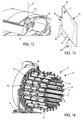
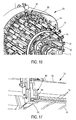
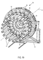
- FIGS. 14 to 17 and 19 and 20 show a portion of the device 2 forming an extractor 70.
- This extractor is slidably mounted with respect to the drum 2. It is also possible for this extractor to be common to several devices 2 and can be Associated at will with one or the other of the drums by moving it opposite these according to the needs. It will be assumed in the following that the horizontal main axis of the extractor coincides with the axis 6.
- the extractor comprises a frame 72 and a set of arms 74 all identical to each other and which are in this case 20 in number, this value not being limiting.
- the arms have an elongated horizontal rectilinear shape. They are regularly distributed around the axis 6 and extend opposite each other. The arms thus define between them an enclosure of generally cylindrical shape with a generally circular section in a plane perpendicular to the axis.
- the arms are cantilevered, all on the same side, by the frame 72 so that the arms are each movably mounted to slide on the frame in a manner that radial direction to the axis 6. At any given moment, all the arms extend at the same radial distance from the axis.
- the extractor is arranged so that the arms can be moved simultaneously in the radial direction and in the same direction so as to approach all the axis or all away from it. At any moment of their movement, the arms are equidistant from the axis 6.
- Each arm has a concave internal face 76 of cylindrical shape with circular section in a plane perpendicular to the axis 6 and facing the latter. These faces are spaced from each other in circumferential direction to the axis.
- Each arm comprises rollers 78 rotatably mounted relative to a body of the arm about a common axis parallel to the axis 6.
- the face 76 has orifices through which the respective rollers can extend projecting from the face in the direction of the axis.
- the rollers of each arm are carried by a common member not shown and itself mounted movable relative to the body of the arm. This organ is able to make pebble take two different positions. In the first position, the rollers protrude from the face 76 in the direction of the axis 6. In the second, they do not extend projecting from this face and are housed integrally inside the arms .
- the extractor comprises centralized means for the control and the operation of the rollers allowing all of them to be placed simultaneously in the same position.
- the extractor is arranged to be able to receive between the arms the entire portion of the drum carrying the wall 10, as illustrated in FIG. figure 16 .
- the wall 10 possibly with the tread blank that it supports, extends facing the faces 76.
- one of the arms 74 is equipped with a retractable clamp 80 comprising two jaws 82, 84 movable relative to one another in radial direction and able to clamp together the free end of the wall 10 for the immobilize rigidly relative to the corresponding arm.
- the clamp 80 immobilizes rigidly relative to the corresponding arm the free end of the wall 10.
- the arms of the extractor are arranged so that the rollers 76 which are in the projecting position, extend in contact with the face 10 or almost in contact with it. The clamps are moved away from the wall 10.
- the drum is rotated relative to the extractor about the axis 6 in the meaning corresponding to the increase of the diameter of the wall. This results in particular the rotation of the end of the wall 10 attached to the drum relative to its other end attached to the extractor. This also causes the increase in the diameter of the turns of the wall 10 which therefore bear against the rollers.
- the arms 74 are moved away so that the rollers accompany the movement of the turns. This positioning of the arms of the extractor makes it possible to evenly distribute the deformation of the turns of the shell, otherwise there is a risk that only part of the turns will deform during the movement.
- the distance between the spacers and the axis 6 is controlled. These operations are continued until the desired external diameter for the wall 10 is obtained.
- the free end of the wall is released by opening and withdrawing the clamp 80, then the flanges 54 are actuated so as to tighten the turns of the wall in the axial direction.
- the drum is then extracted from the extractor.
- the diameter of the wall 10 is adapted as explained above in order to obtain the desired diameter.
- one or more rubber elements are then wound on the wall 10 by rotating the drum about its axis so as to constitute the blank of the tread.
- the drum carrying the blank is introduced into the extractor, the rollers being in the retracted position and therefore not exceeding faces 76.
- the arms of the extractor are then brought closer to the axis in order to place their faces 76 in contact with the blank and to compress it radially. Once this contact is made, the diameter of the wall 10 is reduced as explained above.
- the latter is rotated in the direction in which the turns are tightened on the spacers.
- the blank remains in contact with the arms 74 against which it makes a uniform support and separates from the wall 10 whose diameter is reduced.
- the drum can then be extracted from the blank and the extractor. It is then sufficient to recover the blank always present in the extractor.
- this tread blank will be assembled with the other tire components to form a complete blank to be fired to after vulcanization form a tire casing.
- the device with vibrators 82 able, because of the vibrations they produce, to peel the wall 10 relative to the spacers 20 to facilitate their separation during changes in diameter.
- This variant can make it unnecessary to provide an extractor for changes in diameter.
- the vibrators can be placed under the spacers.
- the frame comprises two disks 90 of axis 6, rigidly fixed to the frame 72.
- the two disks are largely identical to one another. They have the same diameter and are separated by a space along the direction of the axis 6.
- the front disc has in its thickness identical through openings 92 forming rectilinear rectangular rails, the longitudinal direction of the rectangle extending in the radial direction.
- the number of slides is identical to that of the arms.
- Each arm has its rear end portion slidably mounted in the corresponding slide in the radial direction.
- the rear disc comprises radial rods 94 also associated with the arms bijectively, each rod being slidably mounted in the end portion of the corresponding arm.
- the rods are rigidly attached to the rear disc.
- the arms are carried by the two disks and mounted sliding radially on them.
- the extractor further comprises a cam 96 which also has a 6.
- the cam is rotatably mounted about this axis relative to the frame 72 and relative to the discs 90.
- the cam has in its thickness identical through-openings 98 forming rectilinear slideways, the longitudinal direction each slide being inclined relative to the radial direction.
- the slides 98 are the image of one another by a rotation of axis 6 and constant angle The number of slides is identical to that of the arms.
- Each arm at its rear end portion slidably movable in the corresponding slide in the plane of the cam.
- the slide 98 of each arm being inclined relative to the slide 90 of the same arm, the rotation of the cam 96 relative to the discs 90 causes the sliding of the arms in the radial direction.
- the extractor comprises motorization means formed in this case by a jack 100 comprising a body 102 articulated to the frame 72 and a rod 104 hinged to the cam 96.
- the longitudinal direction of the jack is parallel to the general plane of the cam and perpendicular to the axis 6 without being secant with the latter.
- the sliding of the rod relative to the body thus causes the rotation of the cam and the radial sliding of the arms. This mechanism therefore allows the simultaneous movement of the arms, the arms remaining equidistant from the axis at each moment of their movement.
- rollers on the extractor can be provided that the rolling of the rubber component or that of the turns when changing the diameter of the drum is done with a roller or roller device which is independent of the extractor.
- the extractor then performs only the following two functions: first, when increasing the diameter of the drum, maintaining its helical wall along its generator to ensure its uniform deployment so that all the turns have the same amplitude of movement, on the other hand, during the extraction of the rubber ring, maintaining the ring in tension so that it keeps its circular shape while reducing the diameter of the drum in order to prevent the ring from sticking to the spring, follow it and deform.
- roller or rollers could be mounted movable in the axial direction relative to the frame to perform the rolling of different sections of the component.
Landscapes
- Engineering & Computer Science (AREA)
- Mechanical Engineering (AREA)
- Manufacturing & Machinery (AREA)
- Tyre Moulding (AREA)
Claims (15)
- Vorrichtung (2) zur Herstellung eines Reifenbestandteils durch Wickeln, dadurch gekennzeichnet, dass sie Folgendes umfasst:- eine schneckenförmige Außenwand (10), und- Mittel (20) zum Verstellen eines Durchmessers der Wand.
- Vorrichtung nach dem vorangehenden Anspruch, bei der die Wand (10) eine Feder bildet.
- Vorrichtung nach mindestens einem der vorangehenden Ansprüche, die, in der Konfiguration der Mittel zum Verstellen, die der Wand ihren kleinsten Durchmesser verleiht, dergestalt ausgebildet ist, dass die Wand (10) einen minimalen Außendurchmesser (D1) an der Vorrichtung besitzt, der höher als ein Außendurchmesser (D0) ist, den sie im Ruhezustand außerhalb der Vorrichtung besitzt.
- Vorrichtung nach mindestens einem der vorangehenden Ansprüche, die einen Träger (4) umfasst, wobei die Wand ein erstes Ende (40), welches gegenüber seiner Verschiebung bezogen auf den Träger feststehend ist, und ein zweites freies Ende, welches bezogen auf den Träger verschiebbar ist, umfasst.
- Vorrichtung nach dem vorangehenden Anspruch, bei der das erste Ende (40) am Träger angelenkt ist.
- Vorrichtung nach mindestens einem der Ansprüche 4 bis 5, bei der der Träger einen Stift (46) umfasst, der in der Lage ist, gegen verschiedene Zonen (48, 50) einer Windung der Wand, die an das erste Ende angrenzt, nach einer Konfiguration der Wand, abgestützt zu sein.
- Vorrichtung nach mindestens einem der Ansprüche 4 bis 6, bei der der Träger Stege (20), die die Wand tragen und bezogen auf eine Achse (6) der Vorrichtung nach einer zu Achse radialen Richtung beweglich montiert sind, aufweist.
- Vorrichtung nach mindestens einem der Ansprüche 6 bis 7, die dergestalt ausgebildet ist, dass die Wand (10) die Stege durch Reibung gegenüber ihrer Entfernung von der Achse festhält.
- Vorrichtung nach mindestens einem der Ansprüche 4 bis 8, die mindestens ein Organ (82), das in der Lage ist, die Wand und den Träger unter der Einwirkung der von dem Organ erzeugten Vibrationen zu trennen, umfasst.
- Vorrichtung nach mindestens einem der vorangehenden Ansprüche, die mindestens eine Klammer (54), die in der Lage ist, die Windungen der Wand nach einer axialen Richtung der Wand in gegenseitigem Kontakt zu halten, umfasst.
- Vorrichtung nach mindestens einem der vorangehenden Ansprüche, die Arme (74), die in der Lage sind, gegen eine Außenfläche der Wand abgestützt zu sein, umfasst.
- Verfahren zum Erhöhen eines Durchmessers der Wand in einer Vorrichtung nach mindestens einem der vorangehenden Ansprüche, dadurch gekennzeichnet, dass:- zwei Enden der Wand (10), die eine bezogen auf die andere, um eine Achse der Wand in Drehung versetzt werden; danach- eine Konfiguration eines Trägers (4) verändert wird, um ihn mit einer Innenfläche der Wand in Kontakt zu bringen.
- Verfahren nach einem der vorangehenden Ansprüche, bei dem anschließend Windungen der Wand (10) nach der axialen Richtung wieder gespannt werden.
- Verfahren zum Verringern eines Durchmessers der Wand in einer Vorrichtung nach mindestens einem der Ansprüche 1 bis 11, dadurch gekennzeichnet, dass:- eine Konfiguration eines Trägers (4) verändert wird, um einen Kontakt des Trägers mit einer Innenfläche der Wand zu unterbrechen, danach- ein Drehen der Wand auf dem Träger durchgeführt wird.
- Verfahren zur Herstellung einer Lauffläche eines Reifenrohlings, dadurch gekennzeichnet, dass eines oder mehrere Gummielemente auf der Wand (10) einer Vorrichtung nach mindestens einem der Ansprüche 1 bis 11 appliziert werden.
Applications Claiming Priority (2)
| Application Number | Priority Date | Filing Date | Title |
|---|---|---|---|
| FR1259462A FR2996492B1 (fr) | 2012-10-05 | 2012-10-05 | Dispositif de realisation d'une bande de roulement d'une enveloppe de pneumatique |
| PCT/FR2013/052376 WO2014053794A1 (fr) | 2012-10-05 | 2013-10-07 | Dispositif de réalisation d'une bande de roulement d'une enveloppe de pneumatique |
Publications (2)
| Publication Number | Publication Date |
|---|---|
| EP2903808A1 EP2903808A1 (de) | 2015-08-12 |
| EP2903808B1 true EP2903808B1 (de) | 2016-10-05 |
Family
ID=47624252
Family Applications (1)
| Application Number | Title | Priority Date | Filing Date |
|---|---|---|---|
| EP13782807.5A Active EP2903808B1 (de) | 2012-10-05 | 2013-10-07 | Vorrichtung zur herstellung einer lauffläche eines reifenrohlings |
Country Status (5)
| Country | Link |
|---|---|
| US (1) | US10144249B2 (de) |
| EP (1) | EP2903808B1 (de) |
| CN (1) | CN104955634B (de) |
| FR (1) | FR2996492B1 (de) |
| WO (1) | WO2014053794A1 (de) |
Families Citing this family (1)
| Publication number | Priority date | Publication date | Assignee | Title |
|---|---|---|---|---|
| CN108501412A (zh) * | 2018-05-10 | 2018-09-07 | 厦门博瑞达机电工程有限公司 | 一种轮胎胎圈矫正机 |
Family Cites Families (19)
| Publication number | Priority date | Publication date | Assignee | Title |
|---|---|---|---|---|
| US1921594A (en) * | 1928-03-17 | 1933-08-08 | Morgan & Wright | Ply stretching apparatus |
| US1879063A (en) * | 1930-01-09 | 1932-09-27 | Goodrich Co B F | Tire building form or core |
| US3971694A (en) * | 1966-02-25 | 1976-07-27 | Nrm Corporation | Manufacture of radial-carcass tires |
| US3932256A (en) * | 1974-08-19 | 1976-01-13 | The Goodyear Tire & Rubber Company | Tire building drum |
| US4060445A (en) * | 1975-08-25 | 1977-11-29 | The Goodyear Tire & Rubber Company | Building drum for tires and cylindrical articles having axially spaced beads |
| US4330916A (en) * | 1980-10-22 | 1982-05-25 | Pitney Bowes Inc. | Assembly tool |
| CA1204643A (en) * | 1981-09-16 | 1986-05-20 | Hans I. Wallsten | Device for application in blood vessels or other difficulty accessible locations and its use |
| EP0159300A1 (de) * | 1984-03-30 | 1985-10-23 | Stig Westman | Reparaturhülse für Rohre |
| SU1509278A1 (ru) * | 1986-11-10 | 1989-09-23 | Гомельский политехнический институт | Устройство дл изготовлени трубчатых изделий из композиционных материалов |
| JPH01157838A (ja) * | 1987-08-20 | 1989-06-21 | Bridgestone Corp | 成型ドラム |
| US4929298A (en) * | 1988-05-13 | 1990-05-29 | The Goodyear Tire & Rubber Company | Tire building drum including an expandable segmental cylinder assembly and a vacuum chamber |
| US5147370A (en) * | 1991-06-12 | 1992-09-15 | Mcnamara Thomas O | Nitinol stent for hollow body conduits |
| CN2521029Y (zh) * | 2002-02-09 | 2002-11-20 | 天津赛象科技股份有限公司 | 一种贴合鼓 |
| US9216551B2 (en) | 2007-06-11 | 2015-12-22 | Pirelli Tyre S.P.A. | Process and apparatus for manufacturing tyres |
| EP2439061B1 (de) | 2009-06-01 | 2017-01-04 | Bridgestone Corporation | Reifenbautrommel sowie vorrichtung und verfahren zur herstellung von unvulkanisierten reifen |
| WO2011159343A1 (en) * | 2010-06-15 | 2011-12-22 | Bps Engineering, Llc | Transfer ring or drum apparatus having adjustable circumference |
| US8511359B2 (en) * | 2010-09-23 | 2013-08-20 | The Boeing Company | Layup mandrel having changeable shape and method of using the same |
| CN201872357U (zh) * | 2010-10-12 | 2011-06-22 | 双钱集团(如皋)轮胎有限公司 | 一种胶囊反包成型鼓的无间隙撑块 |
| CN202045887U (zh) * | 2011-03-30 | 2011-11-23 | 沈阳冠捷机械有限公司 | 带有无缝隙扇形块的三鼓胶囊成型鼓 |
-
2012
- 2012-10-05 FR FR1259462A patent/FR2996492B1/fr active Active
-
2013
- 2013-10-07 CN CN201380052035.3A patent/CN104955634B/zh active Active
- 2013-10-07 US US14/433,446 patent/US10144249B2/en active Active
- 2013-10-07 WO PCT/FR2013/052376 patent/WO2014053794A1/fr not_active Ceased
- 2013-10-07 EP EP13782807.5A patent/EP2903808B1/de active Active
Also Published As
| Publication number | Publication date |
|---|---|
| FR2996492B1 (fr) | 2014-12-19 |
| FR2996492A1 (fr) | 2014-04-11 |
| US10144249B2 (en) | 2018-12-04 |
| WO2014053794A1 (fr) | 2014-04-10 |
| CN104955634A (zh) | 2015-09-30 |
| US20150290976A1 (en) | 2015-10-15 |
| EP2903808A1 (de) | 2015-08-12 |
| CN104955634B (zh) | 2017-03-08 |
Similar Documents
| Publication | Publication Date | Title |
|---|---|---|
| EP0906186B1 (de) | Aufbautrommel zur luftreifenherstellung | |
| EP3233457B1 (de) | Verfahren und ausrüstung zur montage eines reifenrohlings | |
| EP0875476B1 (de) | Wickler mit zwei Spindeln zum Aufwickeln einer Bahn | |
| EP2903810B1 (de) | Vorrichtung und verfahren zur herstellung einer reifenkomponente aus rohgummi | |
| LU83663A1 (fr) | Perfectionnements apportes aux procedes et aux dispositifs pour la fabrication de pneumatiques | |
| EP3380312B1 (de) | Trommel und verfahren zur montage eines reifenadapters auf einer radfelge | |
| EP3245052B1 (de) | Trommel zum herstellen eines reifenrohlings | |
| EP2903808B1 (de) | Vorrichtung zur herstellung einer lauffläche eines reifenrohlings | |
| EP2903809B1 (de) | Verfahren zur herstellung einer wand einer vorrichtung zur herstellung eines profils eines reifengehäuses | |
| EP0953435B1 (de) | Verfahren zur Herstellung von Luftreifen und Reifenaufbautrommel zur Durchführung dieses Verfahrens | |
| EP2750869B1 (de) | Reifenaufbautrommel mit beweglichen sektoren | |
| FR3066430A1 (fr) | Tambour et procede d'assemblage d'un adaptateur de pneumatique sur une jante | |
| EP0976532A1 (de) | Form für Fahrzeugreifen, und geeignete Vulkanisierpresse zum Aufnehmen einer solchen Form | |
| EP3255510B1 (de) | Kalander und kalandrierverfahren einer schliesszylinderfeder einer uhr | |
| WO2015197935A1 (fr) | Tambour de confection de pneumatique avec des secteurs cylindriques telescopiques | |
| EP3458256B1 (de) | Faltsystem zur herstellung von reifenrohlingen | |
| EP3458254B1 (de) | Aufklappsystem zur herstellung von reifenrohlingen. | |
| EP3458253B1 (de) | Verfahren und vorrichtung zur umschlagung eines reifenrohlings | |
| FR3108556A1 (fr) | Tambour de confection d’un adaptateur de pneumatique sur une jante | |
| FR3140010A1 (fr) | Tambour de fabrication de bandage pourvu d’un dispositif de fixation embarqué comprenant une lame de serrage escamotable | |
| EP1793037B1 (de) | Presswalze mit flexiblem Mantel für eine Schuhpresse | |
| CH712533B1 (fr) | Calandre et procédé de calandrage de ressort de barillet d'horlogerie. | |
| EP1137530A1 (de) | Gerät mit vertikaler achse zum halten einer reifenkarkasse | |
| FR3059593A1 (fr) | Tambour de fabrication d'ebauche ou de composant de pneumatique | |
| FR2873615A1 (fr) | Dispositif d'enroulage d'un manchon cylindrique autour d'un anneau torique |
Legal Events
| Date | Code | Title | Description |
|---|---|---|---|
| PUAI | Public reference made under article 153(3) epc to a published international application that has entered the european phase |
Free format text: ORIGINAL CODE: 0009012 |
|
| 17P | Request for examination filed |
Effective date: 20150325 |
|
| AK | Designated contracting states |
Kind code of ref document: A1 Designated state(s): AL AT BE BG CH CY CZ DE DK EE ES FI FR GB GR HR HU IE IS IT LI LT LU LV MC MK MT NL NO PL PT RO RS SE SI SK SM TR |
|
| AX | Request for extension of the european patent |
Extension state: BA ME |
|
| DAX | Request for extension of the european patent (deleted) | ||
| GRAP | Despatch of communication of intention to grant a patent |
Free format text: ORIGINAL CODE: EPIDOSNIGR1 |
|
| INTG | Intention to grant announced |
Effective date: 20160602 |
|
| GRAS | Grant fee paid |
Free format text: ORIGINAL CODE: EPIDOSNIGR3 |
|
| GRAA | (expected) grant |
Free format text: ORIGINAL CODE: 0009210 |
|
| AK | Designated contracting states |
Kind code of ref document: B1 Designated state(s): AL AT BE BG CH CY CZ DE DK EE ES FI FR GB GR HR HU IE IS IT LI LT LU LV MC MK MT NL NO PL PT RO RS SE SI SK SM TR |
|
| REG | Reference to a national code |
Ref country code: GB Ref legal event code: FG4D Free format text: NOT ENGLISH |
|
| REG | Reference to a national code |
Ref country code: CH Ref legal event code: EP |
|
| REG | Reference to a national code |
Ref country code: AT Ref legal event code: REF Ref document number: 834247 Country of ref document: AT Kind code of ref document: T Effective date: 20161015 |
|
| REG | Reference to a national code |
Ref country code: FR Ref legal event code: PLFP Year of fee payment: 4 |
|
| REG | Reference to a national code |
Ref country code: IE Ref legal event code: FG4D Free format text: LANGUAGE OF EP DOCUMENT: FRENCH |
|
| REG | Reference to a national code |
Ref country code: DE Ref legal event code: R096 Ref document number: 602013012514 Country of ref document: DE |
|
| REG | Reference to a national code |
Ref country code: NL Ref legal event code: FP |
|
| REG | Reference to a national code |
Ref country code: LT Ref legal event code: MG4D |
|
| PG25 | Lapsed in a contracting state [announced via postgrant information from national office to epo] |
Ref country code: LV Free format text: LAPSE BECAUSE OF FAILURE TO SUBMIT A TRANSLATION OF THE DESCRIPTION OR TO PAY THE FEE WITHIN THE PRESCRIBED TIME-LIMIT Effective date: 20161005 Ref country code: BE Free format text: LAPSE BECAUSE OF NON-PAYMENT OF DUE FEES Effective date: 20161031 |
|
| REG | Reference to a national code |
Ref country code: AT Ref legal event code: MK05 Ref document number: 834247 Country of ref document: AT Kind code of ref document: T Effective date: 20161005 |
|
| PG25 | Lapsed in a contracting state [announced via postgrant information from national office to epo] |
Ref country code: SE Free format text: LAPSE BECAUSE OF FAILURE TO SUBMIT A TRANSLATION OF THE DESCRIPTION OR TO PAY THE FEE WITHIN THE PRESCRIBED TIME-LIMIT Effective date: 20161005 Ref country code: LT Free format text: LAPSE BECAUSE OF FAILURE TO SUBMIT A TRANSLATION OF THE DESCRIPTION OR TO PAY THE FEE WITHIN THE PRESCRIBED TIME-LIMIT Effective date: 20161005 Ref country code: NO Free format text: LAPSE BECAUSE OF FAILURE TO SUBMIT A TRANSLATION OF THE DESCRIPTION OR TO PAY THE FEE WITHIN THE PRESCRIBED TIME-LIMIT Effective date: 20170105 Ref country code: GR Free format text: LAPSE BECAUSE OF FAILURE TO SUBMIT A TRANSLATION OF THE DESCRIPTION OR TO PAY THE FEE WITHIN THE PRESCRIBED TIME-LIMIT Effective date: 20170106 |
|
| PG25 | Lapsed in a contracting state [announced via postgrant information from national office to epo] |
Ref country code: FI Free format text: LAPSE BECAUSE OF FAILURE TO SUBMIT A TRANSLATION OF THE DESCRIPTION OR TO PAY THE FEE WITHIN THE PRESCRIBED TIME-LIMIT Effective date: 20161005 Ref country code: IS Free format text: LAPSE BECAUSE OF FAILURE TO SUBMIT A TRANSLATION OF THE DESCRIPTION OR TO PAY THE FEE WITHIN THE PRESCRIBED TIME-LIMIT Effective date: 20170205 Ref country code: PT Free format text: LAPSE BECAUSE OF FAILURE TO SUBMIT A TRANSLATION OF THE DESCRIPTION OR TO PAY THE FEE WITHIN THE PRESCRIBED TIME-LIMIT Effective date: 20170206 Ref country code: HR Free format text: LAPSE BECAUSE OF FAILURE TO SUBMIT A TRANSLATION OF THE DESCRIPTION OR TO PAY THE FEE WITHIN THE PRESCRIBED TIME-LIMIT Effective date: 20161005 Ref country code: ES Free format text: LAPSE BECAUSE OF FAILURE TO SUBMIT A TRANSLATION OF THE DESCRIPTION OR TO PAY THE FEE WITHIN THE PRESCRIBED TIME-LIMIT Effective date: 20161005 Ref country code: PL Free format text: LAPSE BECAUSE OF FAILURE TO SUBMIT A TRANSLATION OF THE DESCRIPTION OR TO PAY THE FEE WITHIN THE PRESCRIBED TIME-LIMIT Effective date: 20161005 Ref country code: AT Free format text: LAPSE BECAUSE OF FAILURE TO SUBMIT A TRANSLATION OF THE DESCRIPTION OR TO PAY THE FEE WITHIN THE PRESCRIBED TIME-LIMIT Effective date: 20161005 Ref country code: RS Free format text: LAPSE BECAUSE OF FAILURE TO SUBMIT A TRANSLATION OF THE DESCRIPTION OR TO PAY THE FEE WITHIN THE PRESCRIBED TIME-LIMIT Effective date: 20161005 |
|
| REG | Reference to a national code |
Ref country code: CH Ref legal event code: PL |
|
| REG | Reference to a national code |
Ref country code: DE Ref legal event code: R097 Ref document number: 602013012514 Country of ref document: DE |
|
| REG | Reference to a national code |
Ref country code: IE Ref legal event code: MM4A |
|
| PG25 | Lapsed in a contracting state [announced via postgrant information from national office to epo] |
Ref country code: CZ Free format text: LAPSE BECAUSE OF FAILURE TO SUBMIT A TRANSLATION OF THE DESCRIPTION OR TO PAY THE FEE WITHIN THE PRESCRIBED TIME-LIMIT Effective date: 20161005 Ref country code: MC Free format text: LAPSE BECAUSE OF FAILURE TO SUBMIT A TRANSLATION OF THE DESCRIPTION OR TO PAY THE FEE WITHIN THE PRESCRIBED TIME-LIMIT Effective date: 20161005 Ref country code: LI Free format text: LAPSE BECAUSE OF NON-PAYMENT OF DUE FEES Effective date: 20161031 Ref country code: SK Free format text: LAPSE BECAUSE OF FAILURE TO SUBMIT A TRANSLATION OF THE DESCRIPTION OR TO PAY THE FEE WITHIN THE PRESCRIBED TIME-LIMIT Effective date: 20161005 Ref country code: CH Free format text: LAPSE BECAUSE OF NON-PAYMENT OF DUE FEES Effective date: 20161031 Ref country code: RO Free format text: LAPSE BECAUSE OF FAILURE TO SUBMIT A TRANSLATION OF THE DESCRIPTION OR TO PAY THE FEE WITHIN THE PRESCRIBED TIME-LIMIT Effective date: 20161005 Ref country code: DK Free format text: LAPSE BECAUSE OF FAILURE TO SUBMIT A TRANSLATION OF THE DESCRIPTION OR TO PAY THE FEE WITHIN THE PRESCRIBED TIME-LIMIT Effective date: 20161005 Ref country code: EE Free format text: LAPSE BECAUSE OF FAILURE TO SUBMIT A TRANSLATION OF THE DESCRIPTION OR TO PAY THE FEE WITHIN THE PRESCRIBED TIME-LIMIT Effective date: 20161005 |
|
| PLBE | No opposition filed within time limit |
Free format text: ORIGINAL CODE: 0009261 |
|
| STAA | Information on the status of an ep patent application or granted ep patent |
Free format text: STATUS: NO OPPOSITION FILED WITHIN TIME LIMIT |
|
| PG25 | Lapsed in a contracting state [announced via postgrant information from national office to epo] |
Ref country code: SM Free format text: LAPSE BECAUSE OF FAILURE TO SUBMIT A TRANSLATION OF THE DESCRIPTION OR TO PAY THE FEE WITHIN THE PRESCRIBED TIME-LIMIT Effective date: 20161005 Ref country code: BG Free format text: LAPSE BECAUSE OF FAILURE TO SUBMIT A TRANSLATION OF THE DESCRIPTION OR TO PAY THE FEE WITHIN THE PRESCRIBED TIME-LIMIT Effective date: 20170105 Ref country code: LU Free format text: LAPSE BECAUSE OF NON-PAYMENT OF DUE FEES Effective date: 20161007 Ref country code: IT Free format text: LAPSE BECAUSE OF FAILURE TO SUBMIT A TRANSLATION OF THE DESCRIPTION OR TO PAY THE FEE WITHIN THE PRESCRIBED TIME-LIMIT Effective date: 20161005 |
|
| 26N | No opposition filed |
Effective date: 20170706 |
|
| REG | Reference to a national code |
Ref country code: FR Ref legal event code: PLFP Year of fee payment: 5 |
|
| PG25 | Lapsed in a contracting state [announced via postgrant information from national office to epo] |
Ref country code: IE Free format text: LAPSE BECAUSE OF NON-PAYMENT OF DUE FEES Effective date: 20161007 Ref country code: SI Free format text: LAPSE BECAUSE OF FAILURE TO SUBMIT A TRANSLATION OF THE DESCRIPTION OR TO PAY THE FEE WITHIN THE PRESCRIBED TIME-LIMIT Effective date: 20161005 |
|
| REG | Reference to a national code |
Ref country code: BE Ref legal event code: MM Effective date: 20161031 |
|
| PG25 | Lapsed in a contracting state [announced via postgrant information from national office to epo] |
Ref country code: HU Free format text: LAPSE BECAUSE OF FAILURE TO SUBMIT A TRANSLATION OF THE DESCRIPTION OR TO PAY THE FEE WITHIN THE PRESCRIBED TIME-LIMIT; INVALID AB INITIO Effective date: 20131007 |
|
| GBPC | Gb: european patent ceased through non-payment of renewal fee |
Effective date: 20171007 |
|
| PG25 | Lapsed in a contracting state [announced via postgrant information from national office to epo] |
Ref country code: MT Free format text: LAPSE BECAUSE OF FAILURE TO SUBMIT A TRANSLATION OF THE DESCRIPTION OR TO PAY THE FEE WITHIN THE PRESCRIBED TIME-LIMIT Effective date: 20161005 Ref country code: CY Free format text: LAPSE BECAUSE OF FAILURE TO SUBMIT A TRANSLATION OF THE DESCRIPTION OR TO PAY THE FEE WITHIN THE PRESCRIBED TIME-LIMIT Effective date: 20161005 Ref country code: MK Free format text: LAPSE BECAUSE OF FAILURE TO SUBMIT A TRANSLATION OF THE DESCRIPTION OR TO PAY THE FEE WITHIN THE PRESCRIBED TIME-LIMIT Effective date: 20161005 |
|
| PG25 | Lapsed in a contracting state [announced via postgrant information from national office to epo] |
Ref country code: GB Free format text: LAPSE BECAUSE OF NON-PAYMENT OF DUE FEES Effective date: 20171007 |
|
| REG | Reference to a national code |
Ref country code: FR Ref legal event code: PLFP Year of fee payment: 6 |
|
| PG25 | Lapsed in a contracting state [announced via postgrant information from national office to epo] |
Ref country code: TR Free format text: LAPSE BECAUSE OF FAILURE TO SUBMIT A TRANSLATION OF THE DESCRIPTION OR TO PAY THE FEE WITHIN THE PRESCRIBED TIME-LIMIT Effective date: 20161005 |
|
| PG25 | Lapsed in a contracting state [announced via postgrant information from national office to epo] |
Ref country code: AL Free format text: LAPSE BECAUSE OF FAILURE TO SUBMIT A TRANSLATION OF THE DESCRIPTION OR TO PAY THE FEE WITHIN THE PRESCRIBED TIME-LIMIT Effective date: 20161005 |
|
| PGFP | Annual fee paid to national office [announced via postgrant information from national office to epo] |
Ref country code: NL Payment date: 20251021 Year of fee payment: 13 |
|
| PGFP | Annual fee paid to national office [announced via postgrant information from national office to epo] |
Ref country code: DE Payment date: 20251021 Year of fee payment: 13 |
|
| PGFP | Annual fee paid to national office [announced via postgrant information from national office to epo] |
Ref country code: FR Payment date: 20251030 Year of fee payment: 13 |