EP2903783B1 - Improved clamp head - Google Patents
Improved clamp head Download PDFInfo
- Publication number
- EP2903783B1 EP2903783B1 EP12787494.9A EP12787494A EP2903783B1 EP 2903783 B1 EP2903783 B1 EP 2903783B1 EP 12787494 A EP12787494 A EP 12787494A EP 2903783 B1 EP2903783 B1 EP 2903783B1
- Authority
- EP
- European Patent Office
- Prior art keywords
- face
- clamp head
- reaction
- clamping
- aperture
- Prior art date
- Legal status (The legal status is an assumption and is not a legal conclusion. Google has not performed a legal analysis and makes no representation as to the accuracy of the status listed.)
- Active
Links
Images





Classifications
-
- B—PERFORMING OPERATIONS; TRANSPORTING
- B25—HAND TOOLS; PORTABLE POWER-DRIVEN TOOLS; MANIPULATORS
- B25B—TOOLS OR BENCH DEVICES NOT OTHERWISE PROVIDED FOR, FOR FASTENING, CONNECTING, DISENGAGING, OR HOLDING
- B25B5/00—Clamps
- B25B5/16—Details, e.g. jaws, jaw attachments
- B25B5/163—Jaws or jaw attachments
-
- B—PERFORMING OPERATIONS; TRANSPORTING
- B25—HAND TOOLS; PORTABLE POWER-DRIVEN TOOLS; MANIPULATORS
- B25B—TOOLS OR BENCH DEVICES NOT OTHERWISE PROVIDED FOR, FOR FASTENING, CONNECTING, DISENGAGING, OR HOLDING
- B25B5/00—Clamps
- B25B5/06—Arrangements for positively actuating jaws
- B25B5/10—Arrangements for positively actuating jaws using screws
- B25B5/104—Arrangements for positively actuating jaws using screws with one screw and one clamping lever and one fulcrum element
- B25B5/105—Arrangements for positively actuating jaws using screws with one screw and one clamping lever and one fulcrum element with one end of the lever resting on a table and the screw being positioned between the ends of the lever
-
- F—MECHANICAL ENGINEERING; LIGHTING; HEATING; WEAPONS; BLASTING
- F16—ENGINEERING ELEMENTS AND UNITS; GENERAL MEASURES FOR PRODUCING AND MAINTAINING EFFECTIVE FUNCTIONING OF MACHINES OR INSTALLATIONS; THERMAL INSULATION IN GENERAL
- F16B—DEVICES FOR FASTENING OR SECURING CONSTRUCTIONAL ELEMENTS OR MACHINE PARTS TOGETHER, e.g. NAILS, BOLTS, CIRCLIPS, CLAMPS, CLIPS OR WEDGES; JOINTS OR JOINTING
- F16B2/00—Friction-grip releasable fastenings
- F16B2/02—Clamps, i.e. with gripping action effected by positive means other than the inherent resistance to deformation of the material of the fastening
- F16B2/06—Clamps, i.e. with gripping action effected by positive means other than the inherent resistance to deformation of the material of the fastening external, i.e. with contracting action
- F16B2/065—Clamps, i.e. with gripping action effected by positive means other than the inherent resistance to deformation of the material of the fastening external, i.e. with contracting action using screw-thread elements
-
- B—PERFORMING OPERATIONS; TRANSPORTING
- B25—HAND TOOLS; PORTABLE POWER-DRIVEN TOOLS; MANIPULATORS
- B25B—TOOLS OR BENCH DEVICES NOT OTHERWISE PROVIDED FOR, FOR FASTENING, CONNECTING, DISENGAGING, OR HOLDING
- B25B5/00—Clamps
- B25B5/06—Arrangements for positively actuating jaws
- B25B5/08—Arrangements for positively actuating jaws using cams
-
- B—PERFORMING OPERATIONS; TRANSPORTING
- B25—HAND TOOLS; PORTABLE POWER-DRIVEN TOOLS; MANIPULATORS
- B25B—TOOLS OR BENCH DEVICES NOT OTHERWISE PROVIDED FOR, FOR FASTENING, CONNECTING, DISENGAGING, OR HOLDING
- B25B5/00—Clamps
- B25B5/06—Arrangements for positively actuating jaws
- B25B5/10—Arrangements for positively actuating jaws using screws
- B25B5/104—Arrangements for positively actuating jaws using screws with one screw and one clamping lever and one fulcrum element
- B25B5/106—Arrangements for positively actuating jaws using screws with one screw and one clamping lever and one fulcrum element with one end of the lever resting on an additional block and the screw being positioned between the ends of the lever
-
- F—MECHANICAL ENGINEERING; LIGHTING; HEATING; WEAPONS; BLASTING
- F16—ENGINEERING ELEMENTS AND UNITS; GENERAL MEASURES FOR PRODUCING AND MAINTAINING EFFECTIVE FUNCTIONING OF MACHINES OR INSTALLATIONS; THERMAL INSULATION IN GENERAL
- F16B—DEVICES FOR FASTENING OR SECURING CONSTRUCTIONAL ELEMENTS OR MACHINE PARTS TOGETHER, e.g. NAILS, BOLTS, CIRCLIPS, CLAMPS, CLIPS OR WEDGES; JOINTS OR JOINTING
- F16B2200/00—Constructional details of connections not covered for in other groups of this subclass
- F16B2200/40—Clamping arrangements where clamping parts are received in recesses of elements to be connected
-
- F—MECHANICAL ENGINEERING; LIGHTING; HEATING; WEAPONS; BLASTING
- F16—ENGINEERING ELEMENTS AND UNITS; GENERAL MEASURES FOR PRODUCING AND MAINTAINING EFFECTIVE FUNCTIONING OF MACHINES OR INSTALLATIONS; THERMAL INSULATION IN GENERAL
- F16B—DEVICES FOR FASTENING OR SECURING CONSTRUCTIONAL ELEMENTS OR MACHINE PARTS TOGETHER, e.g. NAILS, BOLTS, CIRCLIPS, CLAMPS, CLIPS OR WEDGES; JOINTS OR JOINTING
- F16B43/00—Washers or equivalent devices; Other devices for supporting bolt-heads or nuts
- F16B43/02—Washers or equivalent devices; Other devices for supporting bolt-heads or nuts with special provisions for engaging surfaces which are not perpendicular to a bolt axis or do not surround the bolt
- F16B43/025—Washers or equivalent devices; Other devices for supporting bolt-heads or nuts with special provisions for engaging surfaces which are not perpendicular to a bolt axis or do not surround the bolt for surfaces not surrounding the bolt, e.g. hook adaptors for bolts
-
- Y—GENERAL TAGGING OF NEW TECHNOLOGICAL DEVELOPMENTS; GENERAL TAGGING OF CROSS-SECTIONAL TECHNOLOGIES SPANNING OVER SEVERAL SECTIONS OF THE IPC; TECHNICAL SUBJECTS COVERED BY FORMER USPC CROSS-REFERENCE ART COLLECTIONS [XRACs] AND DIGESTS
- Y10—TECHNICAL SUBJECTS COVERED BY FORMER USPC
- Y10T—TECHNICAL SUBJECTS COVERED BY FORMER US CLASSIFICATION
- Y10T403/00—Joints and connections
- Y10T403/33—Transverse rod to spaced plate surfaces
- Y10T403/335—Retainer utilizes or abuts plural plates
Definitions
- the present invention relates to a clamp head and particularly to a clamp head suitable for incorporation in a clamp for structural steelwork.
- Clamp arrangements including a nut and bolt, and at least one shaped clamp head are utilised to attach items to a structural steelwork element, or to connect two structural steel work elements to one another.
- the distance from an engagement surface of the clamp head to a reference plane must be measured or calculated, and the size of the clamp head chosen must be able to accommodate the desired distance. Failure to correctly calculate or measure the distance, or to ignore this requirement in its entirety, can lead to the use of a clamp head, clamp or clamp and packer combination which is not suitable for the job in hand.
- EP 1946891 is an earlier application belonging to the present applicant and discloses a clamp head having an arched body and opposing unequal length arms.
- the arms define a reaction arm having a curved reaction face and a clamping arm having a curved clamping face.
- the curve of the reaction face has a constant radius, and the reaction face is further provided with ribs extending fully across its width.
- EP 0431209 discloses a clamp head configured for use with profile rail.
- the reaction arm of the clamp head is provided with a lip on either side of the reaction face. The lips cooperate to locate the clamp head on the profile rail and to prevent rotation of the clamp head relative to the profile rail.
- DE 2816295 discloses a machine tool clamp having a reaction arm that is significantly longer than the clamping arm. This clamp is susceptible to weakening or cracking of the reaction arm at elevated loads.
- DE2626808 discloses a fastener device having an anti-rotation feature.
- a clamp head comprising an arched body having upper and lower faces, and opposing unequal length arms, the body further having a through aperture for a bolt or like threaded fastener extending between the upper and lower faces, the through aperture tapering outwardly through the body in the direction of the lower face, wherein the arms comprise a reaction arm having at its distal end a curved reaction face extending across the entire width of the reaction arm and a clamping arm having at its distal end a curved clamping face, the curved reaction face have a first edge that is proximal to the clamping face and a second edge that is distal to the clamping face, wherein the radius of curvature of the reaction face increases in the direction of the second edge, wherein further the through aperture intersects the reaction face characterised in that the upper face of the body is provided with a recess configured to receive an insert, wherein further the through aperture extends through the body from a lower region of the recess.
- the reaction face in use, rests against a reaction surface, while the clamping face rests against a clamping surface.
- the intersection of the through aperture with the reaction face provides a cut out in the first edge of the reaction face which accomodates the shank of a fastener when the clamp head is postioned such that it is resting at or near the second edge of the reaction face. Such positioning occurs when the vertical separation between the level of the clamping surface and the reaction surface is at to near the maximum obtainable by the clamp head.
- the through aperture of the clamp head may further intersect the clamping face.
- the intersection of the through aperture with the clamping face provides a cut out in an edge of the clamping face that is proximal to the reaction face.
- the clamping face cut out accomodates the shank of a fastener when the clamp head is postioned such that it is resting at or near the first edge of the reaction face. Such positioning occurs when the vertical separation between the level of the clamping surface and the reaction surface is at to near the minimum obtainable by the clamp head.
- reaction arm By providing the reaction arm with a curved reaction face having an increased radius in the direction of the second edge, it will be appreciated that with increasing clamp angle, i.e. as the clamp pivots about the reaction face to accommodate increasing vertical separation between the level of the clamping surface and the reaction surface, the contact point on the reaction face moves further away from the line of action of a fastener extending through the clamp head.
- the reaction arm is longer than the clamping arm.
- the clamping arm may preferably narrow in the direction of the distal end of the clamping arm.
- the clamping face of the clamping arm is preferably provided with one or more formations which, in use, frictionally engage a clamping surface against which the clamping face rests.
- the formations of the clamping arm may extend in a direction substantially parallel to a longitudinal axis of the clamp head.
- the formations of the clamping arm may, for example, comprise a plurality of teeth, interruptions, abutments, raised facets, crowns or the like which are spaced across the clamping face of the clamping arm.
- the formations additionally prevent rotation of the clamp head, in use.
- the upper surface of the body is provided with an aperture that extends through the body to the lower surface.
- the recess may have substantially parallel sides and a curved base, the recess being adapted to receive a complementarily shaped insert having substantially parallel sides, a curved base and a through aperture, wherein the insert is pivotable within the recess.
- the insert and recess cooperate to align a threaded fastener extending through the clamp head at differing inclination angles, in use, of the clamp head.
- the clamp arrangement may have an elongate threaded fastener such as a nut and bolt extending through the through aperture of the clamp head.
- the nut and bolt may be a conventional nut and bolt where one of the nut and the bolt head is held against rotation and the other of the nut and bolt head is rotated until a predetermined torque has been applied, for example by a torque wrench or driver.
- the bolt may be of the shearing type wherein in the distal end of the bolt shank is configured to break from the remainder of the bolt shank when a predetermined tensile force is reached within the bolt shank.
- the distal end of the shank may be shaped such that it can be held against rotation by an appropriately shaped driver which is able to simultaneously rotate the nut until the desired tensile force is reached.
- the clamp arrangement may include a clamp head having a body, a clamping face, a reaction face and a through aperture, the clamp arrangement having an elongate threaded fastener extending through the through aperture of the clamp head, the threaded fastener including a nut and a bolt of the shearing type wherein, in use, in the distal end of the bolt shank is configured to break from the remainder of the bolt shank when a predetermined tensile force is reached within the bolt shank.
- the clamp head 10 is of a unitary construction comprising a shaped body 12.
- the body 12 is preferably manufactured from metal and is formed by a casting or forging method. As can be seen from the side views, the body 12 has a generally arched shape having two arms 14,16 of unequal length.
- the longer arm 14 may be termed the reaction arm and has a distal end 18.
- the shorter arm 16 may be termed the clamping arm and has a distal end 20.
- the body 12 may further be considered to have an upper side or face 22 and a lower side or face 24.
- the distal end 18 of the reaction arm 14 is rounded and defines a reaction face 26.
- the reaction face 26 extends between a first edge 38 which is proximal to the clamping arm 16 and a second edge 40 which is distal to the clamping arm 16.
- the curve of the reaction face 26 at the first edge 38 has a first radius R1 and the curve of the reaction face 26 at the second edge 40 has a radius R2, where R2 is greater than R1.
- the reaction face 26 is not provided with any formations such as, for example, teeth, interruptions, abutments, raised facets, crowns, grooves, lips, recesses or such like.
- the reaction face 26 is substantially smooth. It will however be understood that the reaction face 26 may be slightly textured as a result of the manner in which the clamp head 10 is manufactured. For example, in the event that the clamp head 10 is manufacured by a metal casting procedure, then the reaction face 26 may have a surface texture arising from the mould or casting sand.
- the reation face 26 extends fully across the reaction arm 14 from one side to the other.
- the distal end 20 of the clamping arm 16 is also rounded and defines a clamping face 28.
- the clamping face 28 and provided with a plurality of teeth 30.
- the teeth 30 are interspersed by spaces 32.
- the teeth 30 and spaces 32 are aligned with the longitudinal axis 34 of the body 12.
- the crown surfaces of the teeth 30 may be considered to constitute portions of the clamping face 28 of the clamp 10 as, in use, the crown surfaces rest against a clamping surface.
- the teeth 30 additionally, in use, resist rotation of the clamp head 10 as indicated by arrow 36 of figure 3 by frictionally engaging the clamping surface against which the clamping face 28 rests, in use.
- the clamping arm 16 narrows in the direction away from the reaction arm 14.
- the body 12 is further provided with a through aperture 42 which extends through the body 12 between the upper and lower sides 22,24. As can be seen from the cross-sectional views, the aperture 42 tapers outwardly in the direction of the lower side 24 of the body 12.
- the aperture 42 is not circular, but instead is oval.
- the upper side 22 of the body 12 is further provided with a recess 44.
- the recess 44 is provided with a curved base 46 and substantially flat side walls 48.
- the side walls 48 are tapered inwardly to a slight degree in the direction of the curved base 46 of the recess 44. This tapering provides a moulding taper for the recess 44 which allows the body 12 to be produced by a metal casting operation.
- the recess 44 is surrounded by a chamfer 49 the function of which is described in greater detail below.
- the through aperture 42 extends down the reaction arm 16 such that the aperture 42 intersects the reaction face 26.
- the through 42 aperture intersects the reaction face 26 such that a cut out 27 is provided in the first edge 38 of the reaction face 26.
- the cut out 27, in use, accomodates the shank of a fastener when the clamp head 10 is postioned such that it is resting at or near the second edge 40 of the reaction face 26. Such positioning occurs when the vertical separation between the level of the clamping surface 28 and the reaction surface 26 is at to near the maximum obtainable by the clamp head 10.
- the through aperture 42 further extends down the clamping arm 14 such that the aperture 42 intersects the clamping face 28.
- the through 42 aperture intersects the clamping face 28 such that a further cut out 29 is provided in an edge 31 of the clamping face 28 that is proximal to the reaction arm 16.
- the further cut out 29, in use accomodates the shank of a fastener when the clamp head 10 is postioned such that it is resting at or near the first edge 38 of the reaction face 26. Such positioning occurs when the vertical separation between the level of the clamping surface 28 and the reaction surface 26 is at to near the minimum obtainable by the clamp head 10.
- the through aperture 24 extends through the body 12 from the curved base 46 of the recess 44.
- the recess 44 receives a complementarily shaped insert 48.
- the insert 48 is also provided with a curved base 51 and substantially flat side walls 50.
- the insert 48 is further provided with a substantially flat top surface 52 and a substantially circular through aperture 54.
- the side walls 50 of the insert 48 taper from the flat top surface 52.
- the tapering of the side walls 50 provides a moulding taper and allows the insert 48 to be produced by a metal casting operation.
- the portions 53 of the curved base 51 which are adjacent the flat top surface 52 of the insert are substantially flat and as such are not continuations of the curve of the base 51.
- the insert 48 is able to "rock" or pivot relative to the clamp head 10 as indicated by arrow 56, and a threaded fastener extends through both aligned apertures 42,54.
- the provision of the chamfer 49 around the recess 44 and the substantially flat portions 53 on the curved base 51 of the insert 48 cooperate so as to ensure that insert 48 does not jam in the recess 44 at extreme pivot angles.
- the recess 44 and insert 48 are complementarily dimensioned so as to have sufficient sideways clearance to avoid jamming as the insert 48 tilts and articulates, in use.
- the threaded fastener may be a conventional nut and bolt where one of the nut and the bolt head is held against rotation and the other of the nut and bolt head is rotated until a predetermined torque has been applied, for example by a torque wrench or driver.
- the bolt may be of the shearing type wherein in the distal end of the bolt shank is configured to break from the remainder of the bolt shank when a predetermined tensile force is reached within the bolt shank.
- the distal end of the shank may be shaped such that it can be held against rotation by an appropriately shaped driver which is able to simultaneously rotate the nut until the desired tensile force is reached.
- Such a shearing type bolt is produced and marketed by Tension Controlled Bolts Ltd under the TCB brand.
Landscapes
- Engineering & Computer Science (AREA)
- Mechanical Engineering (AREA)
- General Engineering & Computer Science (AREA)
- Clamps And Clips (AREA)
Description
- The present invention relates to a clamp head and particularly to a clamp head suitable for incorporation in a clamp for structural steelwork.
- Clamp arrangements including a nut and bolt, and at least one shaped clamp head are utilised to attach items to a structural steelwork element, or to connect two structural steel work elements to one another. Typically, the distance from an engagement surface of the clamp head to a reference plane must be measured or calculated, and the size of the clamp head chosen must be able to accommodate the desired distance. Failure to correctly calculate or measure the distance, or to ignore this requirement in its entirety, can lead to the use of a clamp head, clamp or clamp and packer combination which is not suitable for the job in hand.
-
EP 1946891 is an earlier application belonging to the present applicant and discloses a clamp head having an arched body and opposing unequal length arms. The arms define a reaction arm having a curved reaction face and a clamping arm having a curved clamping face. The curve of the reaction face has a constant radius, and the reaction face is further provided with ribs extending fully across its width.EP 0431209 discloses a clamp head configured for use with profile rail. The reaction arm of the clamp head is provided with a lip on either side of the reaction face. The lips cooperate to locate the clamp head on the profile rail and to prevent rotation of the clamp head relative to the profile rail.DE 2816295 discloses a machine tool clamp having a reaction arm that is significantly longer than the clamping arm. This clamp is susceptible to weakening or cracking of the reaction arm at elevated loads.
DE2626808 discloses a fastener device having an anti-rotation feature. - According to the present invention there is provided a clamp head comprising an arched body having upper and lower faces, and opposing unequal length arms, the body further having a through aperture for a bolt or like threaded fastener extending between the upper and lower faces, the through aperture tapering outwardly through the body in the direction of the lower face, wherein the arms comprise a reaction arm having at its distal end a curved reaction face extending across the entire width of the reaction arm and a clamping arm having at its distal end a curved clamping face, the curved reaction face have a first edge that is proximal to the clamping face and a second edge that is distal to the clamping face, wherein the radius of curvature of the reaction face increases in the direction of the second edge, wherein further the through aperture intersects the reaction face characterised in that the upper face of the body is provided with a recess configured to receive an insert, wherein further the through aperture extends through the body from a lower region of the recess.
- The reaction face, in use, rests against a reaction surface, while the clamping face rests against a clamping surface. The intersection of the through aperture with the reaction face provides a cut out in the first edge of the reaction face which accomodates the shank of a fastener when the clamp head is postioned such that it is resting at or near the second edge of the reaction face. Such positioning occurs when the vertical separation between the level of the clamping surface and the reaction surface is at to near the maximum obtainable by the clamp head.
- The through aperture of the clamp head may further intersect the clamping face. The intersection of the through aperture with the clamping face provides a cut out in an edge of the clamping face that is proximal to the reaction face. The clamping face cut out accomodates the shank of a fastener when the clamp head is postioned such that it is resting at or near the first edge of the reaction face. Such positioning occurs when the vertical separation between the level of the clamping surface and the reaction surface is at to near the minimum obtainable by the clamp head.
- By providing the reaction arm with a curved reaction face having an increased radius in the direction of the second edge, it will be appreciated that with increasing clamp angle, i.e. as the clamp pivots about the reaction face to accommodate increasing vertical separation between the level of the clamping surface and the reaction surface, the contact point on the reaction face moves further away from the line of action of a fastener extending through the clamp head.
- In a preferred embodiment, the reaction arm is longer than the clamping arm. The clamping arm may preferably narrow in the direction of the distal end of the clamping arm.
- The clamping face of the clamping arm is preferably provided with one or more formations which, in use, frictionally engage a clamping surface against which the clamping face rests. The formations of the clamping arm may extend in a direction substantially parallel to a longitudinal axis of the clamp head. The formations of the clamping arm may, for example, comprise a plurality of teeth, interruptions, abutments, raised facets, crowns or the like which are spaced across the clamping face of the clamping arm. The formations additionally prevent rotation of the clamp head, in use.
- The upper surface of the body is provided with an aperture that extends through the body to the lower surface. The recess may have substantially parallel sides and a curved base, the recess being adapted to receive a complementarily shaped insert having substantially parallel sides, a curved base and a through aperture, wherein the insert is pivotable within the recess. The insert and recess cooperate to align a threaded fastener extending through the clamp head at differing inclination angles, in use, of the clamp head.
- The clamp arrangement may have an elongate threaded fastener such as a nut and bolt extending through the through aperture of the clamp head.
- The nut and bolt may be a conventional nut and bolt where one of the nut and the bolt head is held against rotation and the other of the nut and bolt head is rotated until a predetermined torque has been applied, for example by a torque wrench or driver. Alternatively, the bolt may be of the shearing type wherein in the distal end of the bolt shank is configured to break from the remainder of the bolt shank when a predetermined tensile force is reached within the bolt shank. In such an arrangement the distal end of the shank may be shaped such that it can be held against rotation by an appropriately shaped driver which is able to simultaneously rotate the nut until the desired tensile force is reached.
- The clamp arrangement may include a clamp head having a body, a clamping face, a reaction face and a through aperture, the clamp arrangement having an elongate threaded fastener extending through the through aperture of the clamp head, the threaded fastener including a nut and a bolt of the shearing type wherein, in use, in the distal end of the bolt shank is configured to break from the remainder of the bolt shank when a predetermined tensile force is reached within the bolt shank.
- An embodiment of the present invention will now be described with reference to the accompanying drawings in which:
-
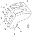
Figure 1 shows a perspective view from above and to one side of a clamp head according to the present invention; -
Figure 2 shows a side view of the clamp head; -
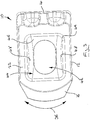
Figure 3 shows a top plan view of the clamp head; -
Figure 4 is a bottom plan view of the clamp head; -
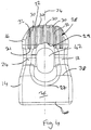
Figure 5 is a front view of the clamp head; -
Figure 6 is a rear view of the clamp head; -
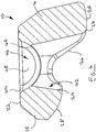
Figure 7 is a cross-sectional view of the clamp head as indicated by arrows A-A offigure 5 ; -
Figure 8 is a perspective view from above and to one side of the clamp head and a pivotable insert; and -
Figure 9 shows a side view of the clamp head and insert offigure 8 . - Referring to the figures there is shown a clamp head generally designated 10. The
clamp head 10 is of a unitary construction comprising ashaped body 12. Thebody 12 is preferably manufactured from metal and is formed by a casting or forging method. As can be seen from the side views, thebody 12 has a generally arched shape having twoarms longer arm 14 may be termed the reaction arm and has a distal end 18. Theshorter arm 16 may be termed the clamping arm and has a distal end 20. The basis for this terminology is described in greater detail below. Thebody 12 may further be considered to have an upper side orface 22 and a lower side orface 24. - The distal end 18 of the
reaction arm 14 is rounded and defines areaction face 26. Thereaction face 26 extends between afirst edge 38 which is proximal to theclamping arm 16 and asecond edge 40 which is distal to theclamping arm 16. As can be seen illustrated onfigure 2 , the curve of thereaction face 26 at thefirst edge 38 has a first radius R1 and the curve of thereaction face 26 at thesecond edge 40 has a radius R2, where R2 is greater than R1. By providing thereaction arm 14 with acurved reaction face 26 having an increased radius in the direction of thesecond edge 40, it will be appreciated that with increasing clamp angle, i.e. as theclamp head 10 pivots about thereaction face 26 to accommodate increasing vertical separation between the level of the clamping surface and the reaction surface, the contact point on thereaction face 26 moves further away from the line of action of a fastener extending through theclamp head 10. Thereaction face 26 is not provided with any formations such as, for example, teeth, interruptions, abutments, raised facets, crowns, grooves, lips, recesses or such like. Thereaction face 26 is substantially smooth. It will however be understood that thereaction face 26 may be slightly textured as a result of the manner in which theclamp head 10 is manufactured. For example, in the event that theclamp head 10 is manufacured by a metal casting procedure, then thereaction face 26 may have a surface texture arising from the mould or casting sand. Thereation face 26 extends fully across thereaction arm 14 from one side to the other. - The distal end 20 of the
clamping arm 16 is also rounded and defines a clampingface 28. Theclamping face 28 and provided with a plurality ofteeth 30. Theteeth 30 are interspersed byspaces 32. Theteeth 30 andspaces 32 are aligned with thelongitudinal axis 34 of thebody 12. The crown surfaces of theteeth 30 may be considered to constitute portions of the clampingface 28 of theclamp 10 as, in use, the crown surfaces rest against a clamping surface. Theteeth 30 additionally, in use, resist rotation of theclamp head 10 as indicated by arrow 36 offigure 3 by frictionally engaging the clamping surface against which the clampingface 28 rests, in use. The clampingarm 16 narrows in the direction away from thereaction arm 14. - The
body 12 is further provided with a throughaperture 42 which extends through thebody 12 between the upper andlower sides aperture 42 tapers outwardly in the direction of thelower side 24 of thebody 12. Theaperture 42 is not circular, but instead is oval. Theupper side 22 of thebody 12 is further provided with arecess 44. Therecess 44 is provided with acurved base 46 and substantiallyflat side walls 48. Theside walls 48 are tapered inwardly to a slight degree in the direction of thecurved base 46 of therecess 44. This tapering provides a moulding taper for therecess 44 which allows thebody 12 to be produced by a metal casting operation. Therecess 44 is surrounded by achamfer 49 the function of which is described in greater detail below. - The through
aperture 42 extends down thereaction arm 16 such that theaperture 42 intersects thereaction face 26. The through 42 aperture intersects thereaction face 26 such that a cut out 27 is provided in thefirst edge 38 of thereaction face 26. The cut out 27, in use, accomodates the shank of a fastener when theclamp head 10 is postioned such that it is resting at or near thesecond edge 40 of thereaction face 26. Such positioning occurs when the vertical separation between the level of the clampingsurface 28 and thereaction surface 26 is at to near the maximum obtainable by theclamp head 10. - The through
aperture 42 further extends down the clampingarm 14 such that theaperture 42 intersects the clampingface 28. The through 42 aperture intersects the clampingface 28 such that a further cut out 29 is provided in anedge 31 of the clampingface 28 that is proximal to thereaction arm 16. The further cut out 29, in use, accomodates the shank of a fastener when theclamp head 10 is postioned such that it is resting at or near thefirst edge 38 of thereaction face 26. Such positioning occurs when the vertical separation between the level of the clampingsurface 28 and thereaction surface 26 is at to near the minimum obtainable by theclamp head 10. - The through
aperture 24 extends through thebody 12 from thecurved base 46 of therecess 44. In use, and as can be seen infigures 8 and9 , therecess 44 receives a complementarily shapedinsert 48. Theinsert 48 is also provided with a curved base 51 and substantiallyflat side walls 50. Theinsert 48 is further provided with a substantially flattop surface 52 and a substantially circular throughaperture 54. In a similar manner to theside walls 48 of therecess 44, theside walls 50 of theinsert 48 taper from the flattop surface 52. As before, the tapering of theside walls 50 provides a moulding taper and allows theinsert 48 to be produced by a metal casting operation. Theportions 53 of the curved base 51 which are adjacent the flattop surface 52 of the insert are substantially flat and as such are not continuations of the curve of the base 51. - In use, the
insert 48 is able to "rock" or pivot relative to theclamp head 10 as indicated byarrow 56, and a threaded fastener extends through both alignedapertures chamfer 49 around therecess 44 and the substantiallyflat portions 53 on the curved base 51 of theinsert 48 cooperate so as to ensure thatinsert 48 does not jam in therecess 44 at extreme pivot angles. It will further be appreciated that therecess 44 and insert 48 are complementarily dimensioned so as to have sufficient sideways clearance to avoid jamming as theinsert 48 tilts and articulates, in use. - In use, the threaded fastener may be a conventional nut and bolt where one of the nut and the bolt head is held against rotation and the other of the nut and bolt head is rotated until a predetermined torque has been applied, for example by a torque wrench or driver. Alternatively, the bolt may be of the shearing type wherein in the distal end of the bolt shank is configured to break from the remainder of the bolt shank when a predetermined tensile force is reached within the bolt shank. In such an arrangement the distal end of the shank may be shaped such that it can be held against rotation by an appropriately shaped driver which is able to simultaneously rotate the nut until the desired tensile force is reached. Such a shearing type bolt is produced and marketed by Tension Controlled Bolts Ltd under the TCB brand.
Claims (12)
- A clamp head (10) comprising an arched body (12) having upper and lower faces (22,24), and opposing unequal length arms (14,16), the body (12) further having a through aperture (42) for a bolt or like threaded fastener extending between the upper and lower faces (22,24), the through aperture (42) tapering outwardly through the body (12) in the direction of the lower face (24), wherein the arms (14,16) comprise a reaction arm (14) having at its distal end a curved reaction face (26) extending across the entire width of the reaction arm (14) and a clamping arm (16) having at its distal end a curved clamping face (28), the curved reaction face (26) has a first edge (38) that is proximal to the clamping face (28) and a second edge (40) that is distal to the clamping face (28), wherein the radius of curvature of the reaction face (26) increases in the direction of the second edge (40), wherein further the through aperture (42) intersects the reaction face (26) characterised in that the upper face (22) of the body (12) is provided with a recess (44) configured to receive an insert (48), wherein further the through aperture (42) extends through the body (12) from a lower region of the recess (44).
- A clamp head (10) as claimed in claim 1 wherein the through aperture (42) intersects the clamping face (28).
- A clamp head (10) as claimed in claim 1 or claim 2 wherein the reaction arm (14) is longer than the clamping arm (16).
- A clamp head (10) as claimed in any preceding claim wherein the clamping arm (16) narrows in the direction of the distal end (20) of the clamping arm (16).
- A clamp head (10) as claimed in any preceding claim wherein the clamping face (28) of the clamping arm (16) is provided with one or more formations which, in use, frictionally engage a clamping surface against which the clamping face (28) rests.
- A clamp head (10) as claimed in claim 5 wherein the formations of the clamping arm (16) extend in a direction substantially parallel to a longitudinal axis of the clamp head.
- A clamp head (10) as claimed in claim 5 or claim 6 wherein the formations of the clamping arm (16) comprise a plurality of teeth (30), interruptions, abutments, raised facets, crowns or the like which are spaced across the clamping face (28) of the clamping arm (16).
- A clamp head (10) as claimed in claim in any preceding claim wherein the recess (44) has substantially parallel sides (48) and a curved base (46), the recess (44) being adapted to receive a complementarily shaped insert (48) having substantially parallel sides (50), a curved base (51) and a through aperture (54), wherein the insert (48) is pivotable within the recess (44).
- A clamp head (10) as claimed in any preceding claim wherein the reaction face (26) is free from formations which, in use, frictionally engage a reaction surface against which the reaction face (26) rests.
- A clamp arrangement including a clamp head (10) as claimed in any preceding claim, the clamp arrangement having an elongate threaded fastener extending through the through aperture (42) of the clamp head (10).
- A clamp arrangement as claimed in claim 10 wherein the threaded fastener is a conventionally configured nut and bolt where, in use, one of the nut and the bolt head is held against rotation and the other of the nut and bolt head is rotated until a predetermined torque has been applied.
- A clamp arrangement as claimed in claim 10 wherein the threaded fastener includes a nut and a bolt of the shearing type wherein, in use, in the distal end of the bolt shank is configured to break from the remainder of the bolt shank when a predetermined tensile force is reached within the bolt shank.
Applications Claiming Priority (1)
| Application Number | Priority Date | Filing Date | Title |
|---|---|---|---|
| PCT/IB2012/001925 WO2014053868A1 (en) | 2012-10-01 | 2012-10-01 | Improved clamp head |
Publications (2)
| Publication Number | Publication Date |
|---|---|
| EP2903783A1 EP2903783A1 (en) | 2015-08-12 |
| EP2903783B1 true EP2903783B1 (en) | 2016-12-14 |
Family
ID=50434409
Family Applications (1)
| Application Number | Title | Priority Date | Filing Date |
|---|---|---|---|
| EP12787494.9A Active EP2903783B1 (en) | 2012-10-01 | 2012-10-01 | Improved clamp head |
Country Status (5)
| Country | Link |
|---|---|
| US (1) | US9597780B2 (en) |
| EP (1) | EP2903783B1 (en) |
| AU (1) | AU2012391695B2 (en) |
| CA (1) | CA2885903C (en) |
| WO (1) | WO2014053868A1 (en) |
Families Citing this family (3)
| Publication number | Priority date | Publication date | Assignee | Title |
|---|---|---|---|---|
| AU2012391695B2 (en) | 2012-10-01 | 2017-05-18 | Ev Ip Lp | Improved clamp head |
| USD898860S1 (en) * | 2019-05-09 | 2020-10-13 | Aimlock Inc. | Semiautonomous weapon mount |
| USD898859S1 (en) * | 2019-05-09 | 2020-10-13 | Aimlock Inc. | Semiautonomous weapon mount |
Family Cites Families (17)
| Publication number | Priority date | Publication date | Assignee | Title |
|---|---|---|---|---|
| US1346504A (en) * | 1919-01-29 | 1920-07-13 | Mathison Albert Olai | Work-holding device |
| US2175453A (en) * | 1938-01-24 | 1939-10-10 | T B F Company | Clamp |
| US2210249A (en) * | 1938-09-12 | 1940-08-06 | Lindsay Ltd Henry | Means for clamping girders and the like together |
| US2365079A (en) * | 1943-08-31 | 1944-12-12 | Westinghouse Electric & Mfg Co | Work-holding apparatus |
| GB629096A (en) * | 1946-08-22 | 1949-09-12 | Lindsay Ltd Henry | Improvements in or relating to clips or the like for securing flanges of rails, girders and like articles or structures to adjacent articles or structures |
| US3210069A (en) * | 1963-04-16 | 1965-10-05 | Leonard J Holtz | Hold-down clamp |
| GB1530463A (en) * | 1975-06-19 | 1978-11-01 | Lindsay Ltd Henry | Fastener devices |
| DE2816295A1 (en) | 1978-04-14 | 1979-10-25 | Lenzkes Karl Heinz | Clamp for machine tool fixtures - comprises curved bar allowing adjustment for position at right angles to direction of T=slots |
| USD322259S (en) * | 1989-02-08 | 1991-12-10 | Quandt Albert C | Die holddown clamp |
| EP0431209B1 (en) * | 1989-12-06 | 1994-07-27 | Erico Gmbh | Device for clamping rails or the like |
| US5451116A (en) * | 1992-06-09 | 1995-09-19 | General Electric Company | Tripod plate for turbine flowpath |
| DE29915435U1 (en) * | 1999-09-03 | 2001-01-18 | Halfen GmbH & Co. Kommanditgesellschaft, 40764 Langenfeld | Beam clamp |
| DE20116015U1 (en) * | 2001-04-12 | 2002-03-07 | LISEGA GmbH, 27404 Zeven | Clamping device for clamping beams |
| USD597393S1 (en) * | 2007-01-16 | 2009-08-04 | Ev Ip Lp | Clamp head |
| GB0700818D0 (en) | 2007-01-16 | 2007-02-21 | Tyco Europe Metal Framing Ltd | Clamp head |
| AU2012391695B2 (en) | 2012-10-01 | 2017-05-18 | Ev Ip Lp | Improved clamp head |
| USD762436S1 (en) * | 2015-04-09 | 2016-08-02 | Ev Ip Lp | Clamp head |
-
2012
- 2012-10-01 AU AU2012391695A patent/AU2012391695B2/en active Active
- 2012-10-01 EP EP12787494.9A patent/EP2903783B1/en active Active
- 2012-10-01 CA CA2885903A patent/CA2885903C/en active Active
- 2012-10-01 US US14/432,582 patent/US9597780B2/en active Active
- 2012-10-01 WO PCT/IB2012/001925 patent/WO2014053868A1/en not_active Ceased
Non-Patent Citations (1)
| Title |
|---|
| None * |
Also Published As
| Publication number | Publication date |
|---|---|
| AU2012391695B2 (en) | 2017-05-18 |
| EP2903783A1 (en) | 2015-08-12 |
| AU2012391695A1 (en) | 2015-04-16 |
| CA2885903A1 (en) | 2014-04-10 |
| WO2014053868A1 (en) | 2014-04-10 |
| CA2885903C (en) | 2019-10-29 |
| US9597780B2 (en) | 2017-03-21 |
| US20150266165A1 (en) | 2015-09-24 |
Similar Documents
| Publication | Publication Date | Title |
|---|---|---|
| US4607547A (en) | Stripped hex head drive socket | |
| JP5024483B2 (en) | Cutting insert | |
| EP2210984B1 (en) | Releasable coupling assembly for a wear member of an excavating equipment | |
| CA2618413C (en) | Clamp head | |
| US20130263382A1 (en) | Prying tools with glide members | |
| EP2898150B1 (en) | Lock for tool holder | |
| CA2885903C (en) | Improved clamp head | |
| SE520997C2 (en) | Reversible cutter with grooved coupling surface against the holder and central material portion for fasteners | |
| SE501914C2 (en) | Tool shank with detachable blade | |
| AU2020317370B2 (en) | Protection systems | |
| US9782841B2 (en) | Cutting tool | |
| EP2995405A1 (en) | Cutting insert, tool body on which said cutting insert can be mounted, and exchangeable edge cutting tool and ball end mill provided with same | |
| US6273379B1 (en) | Climbing nut | |
| JP6748084B2 (en) | Tooth block for crushing tool | |
| AU2010201078A1 (en) | Drive system for threaded fasteners | |
| GB2544755A (en) | Braking element | |
| WO2013032394A1 (en) | A device for the fastening of wear members and a system comprising such a device |
Legal Events
| Date | Code | Title | Description |
|---|---|---|---|
| PUAI | Public reference made under article 153(3) epc to a published international application that has entered the european phase |
Free format text: ORIGINAL CODE: 0009012 |
|
| 17P | Request for examination filed |
Effective date: 20150324 |
|
| AK | Designated contracting states |
Kind code of ref document: A1 Designated state(s): AL AT BE BG CH CY CZ DE DK EE ES FI FR GB GR HR HU IE IS IT LI LT LU LV MC MK MT NL NO PL PT RO RS SE SI SK SM TR |
|
| AX | Request for extension of the european patent |
Extension state: BA ME |
|
| DAX | Request for extension of the european patent (deleted) | ||
| GRAP | Despatch of communication of intention to grant a patent |
Free format text: ORIGINAL CODE: EPIDOSNIGR1 |
|
| INTG | Intention to grant announced |
Effective date: 20160715 |
|
| STAA | Information on the status of an ep patent application or granted ep patent |
Free format text: STATUS: GRANT OF PATENT IS INTENDED |
|
| GRAS | Grant fee paid |
Free format text: ORIGINAL CODE: EPIDOSNIGR3 |
|
| GRAA | (expected) grant |
Free format text: ORIGINAL CODE: 0009210 |
|
| STAA | Information on the status of an ep patent application or granted ep patent |
Free format text: STATUS: THE PATENT HAS BEEN GRANTED |
|
| AK | Designated contracting states |
Kind code of ref document: B1 Designated state(s): AL AT BE BG CH CY CZ DE DK EE ES FI FR GB GR HR HU IE IS IT LI LT LU LV MC MK MT NL NO PL PT RO RS SE SI SK SM TR |
|
| REG | Reference to a national code |
Ref country code: GB Ref legal event code: FG4D |
|
| REG | Reference to a national code |
Ref country code: CH Ref legal event code: EP |
|
| REG | Reference to a national code |
Ref country code: IE Ref legal event code: FG4D |
|
| REG | Reference to a national code |
Ref country code: AT Ref legal event code: REF Ref document number: 853145 Country of ref document: AT Kind code of ref document: T Effective date: 20170115 |
|
| REG | Reference to a national code |
Ref country code: DE Ref legal event code: R096 Ref document number: 602012026669 Country of ref document: DE |
|
| PG25 | Lapsed in a contracting state [announced via postgrant information from national office to epo] |
Ref country code: LV Free format text: LAPSE BECAUSE OF FAILURE TO SUBMIT A TRANSLATION OF THE DESCRIPTION OR TO PAY THE FEE WITHIN THE PRESCRIBED TIME-LIMIT Effective date: 20161214 |
|
| REG | Reference to a national code |
Ref country code: LT Ref legal event code: MG4D |
|
| REG | Reference to a national code |
Ref country code: NL Ref legal event code: MP Effective date: 20161214 |
|
| PG25 | Lapsed in a contracting state [announced via postgrant information from national office to epo] |
Ref country code: GR Free format text: LAPSE BECAUSE OF FAILURE TO SUBMIT A TRANSLATION OF THE DESCRIPTION OR TO PAY THE FEE WITHIN THE PRESCRIBED TIME-LIMIT Effective date: 20170315 Ref country code: LT Free format text: LAPSE BECAUSE OF FAILURE TO SUBMIT A TRANSLATION OF THE DESCRIPTION OR TO PAY THE FEE WITHIN THE PRESCRIBED TIME-LIMIT Effective date: 20161214 Ref country code: NO Free format text: LAPSE BECAUSE OF FAILURE TO SUBMIT A TRANSLATION OF THE DESCRIPTION OR TO PAY THE FEE WITHIN THE PRESCRIBED TIME-LIMIT Effective date: 20170314 Ref country code: SE Free format text: LAPSE BECAUSE OF FAILURE TO SUBMIT A TRANSLATION OF THE DESCRIPTION OR TO PAY THE FEE WITHIN THE PRESCRIBED TIME-LIMIT Effective date: 20161214 |
|
| REG | Reference to a national code |
Ref country code: AT Ref legal event code: MK05 Ref document number: 853145 Country of ref document: AT Kind code of ref document: T Effective date: 20161214 |
|
| PG25 | Lapsed in a contracting state [announced via postgrant information from national office to epo] |
Ref country code: RS Free format text: LAPSE BECAUSE OF FAILURE TO SUBMIT A TRANSLATION OF THE DESCRIPTION OR TO PAY THE FEE WITHIN THE PRESCRIBED TIME-LIMIT Effective date: 20161214 Ref country code: HR Free format text: LAPSE BECAUSE OF FAILURE TO SUBMIT A TRANSLATION OF THE DESCRIPTION OR TO PAY THE FEE WITHIN THE PRESCRIBED TIME-LIMIT Effective date: 20161214 Ref country code: FI Free format text: LAPSE BECAUSE OF FAILURE TO SUBMIT A TRANSLATION OF THE DESCRIPTION OR TO PAY THE FEE WITHIN THE PRESCRIBED TIME-LIMIT Effective date: 20161214 |
|
| PG25 | Lapsed in a contracting state [announced via postgrant information from national office to epo] |
Ref country code: NL Free format text: LAPSE BECAUSE OF FAILURE TO SUBMIT A TRANSLATION OF THE DESCRIPTION OR TO PAY THE FEE WITHIN THE PRESCRIBED TIME-LIMIT Effective date: 20161214 |
|
| PG25 | Lapsed in a contracting state [announced via postgrant information from national office to epo] |
Ref country code: IS Free format text: LAPSE BECAUSE OF FAILURE TO SUBMIT A TRANSLATION OF THE DESCRIPTION OR TO PAY THE FEE WITHIN THE PRESCRIBED TIME-LIMIT Effective date: 20170414 Ref country code: EE Free format text: LAPSE BECAUSE OF FAILURE TO SUBMIT A TRANSLATION OF THE DESCRIPTION OR TO PAY THE FEE WITHIN THE PRESCRIBED TIME-LIMIT Effective date: 20161214 Ref country code: CZ Free format text: LAPSE BECAUSE OF FAILURE TO SUBMIT A TRANSLATION OF THE DESCRIPTION OR TO PAY THE FEE WITHIN THE PRESCRIBED TIME-LIMIT Effective date: 20161214 Ref country code: RO Free format text: LAPSE BECAUSE OF FAILURE TO SUBMIT A TRANSLATION OF THE DESCRIPTION OR TO PAY THE FEE WITHIN THE PRESCRIBED TIME-LIMIT Effective date: 20161214 Ref country code: SK Free format text: LAPSE BECAUSE OF FAILURE TO SUBMIT A TRANSLATION OF THE DESCRIPTION OR TO PAY THE FEE WITHIN THE PRESCRIBED TIME-LIMIT Effective date: 20161214 |
|
| PG25 | Lapsed in a contracting state [announced via postgrant information from national office to epo] |
Ref country code: BE Free format text: LAPSE BECAUSE OF FAILURE TO SUBMIT A TRANSLATION OF THE DESCRIPTION OR TO PAY THE FEE WITHIN THE PRESCRIBED TIME-LIMIT Effective date: 20161214 Ref country code: ES Free format text: LAPSE BECAUSE OF FAILURE TO SUBMIT A TRANSLATION OF THE DESCRIPTION OR TO PAY THE FEE WITHIN THE PRESCRIBED TIME-LIMIT Effective date: 20161214 Ref country code: IT Free format text: LAPSE BECAUSE OF FAILURE TO SUBMIT A TRANSLATION OF THE DESCRIPTION OR TO PAY THE FEE WITHIN THE PRESCRIBED TIME-LIMIT Effective date: 20161214 Ref country code: SM Free format text: LAPSE BECAUSE OF FAILURE TO SUBMIT A TRANSLATION OF THE DESCRIPTION OR TO PAY THE FEE WITHIN THE PRESCRIBED TIME-LIMIT Effective date: 20161214 Ref country code: AT Free format text: LAPSE BECAUSE OF FAILURE TO SUBMIT A TRANSLATION OF THE DESCRIPTION OR TO PAY THE FEE WITHIN THE PRESCRIBED TIME-LIMIT Effective date: 20161214 Ref country code: BG Free format text: LAPSE BECAUSE OF FAILURE TO SUBMIT A TRANSLATION OF THE DESCRIPTION OR TO PAY THE FEE WITHIN THE PRESCRIBED TIME-LIMIT Effective date: 20170314 Ref country code: PL Free format text: LAPSE BECAUSE OF FAILURE TO SUBMIT A TRANSLATION OF THE DESCRIPTION OR TO PAY THE FEE WITHIN THE PRESCRIBED TIME-LIMIT Effective date: 20161214 Ref country code: PT Free format text: LAPSE BECAUSE OF FAILURE TO SUBMIT A TRANSLATION OF THE DESCRIPTION OR TO PAY THE FEE WITHIN THE PRESCRIBED TIME-LIMIT Effective date: 20170414 |
|
| REG | Reference to a national code |
Ref country code: DE Ref legal event code: R097 Ref document number: 602012026669 Country of ref document: DE |
|
| PLBE | No opposition filed within time limit |
Free format text: ORIGINAL CODE: 0009261 |
|
| STAA | Information on the status of an ep patent application or granted ep patent |
Free format text: STATUS: NO OPPOSITION FILED WITHIN TIME LIMIT |
|
| REG | Reference to a national code |
Ref country code: FR Ref legal event code: PLFP Year of fee payment: 6 |
|
| 26N | No opposition filed |
Effective date: 20170915 |
|
| PG25 | Lapsed in a contracting state [announced via postgrant information from national office to epo] |
Ref country code: DK Free format text: LAPSE BECAUSE OF FAILURE TO SUBMIT A TRANSLATION OF THE DESCRIPTION OR TO PAY THE FEE WITHIN THE PRESCRIBED TIME-LIMIT Effective date: 20161214 |
|
| PG25 | Lapsed in a contracting state [announced via postgrant information from national office to epo] |
Ref country code: SI Free format text: LAPSE BECAUSE OF FAILURE TO SUBMIT A TRANSLATION OF THE DESCRIPTION OR TO PAY THE FEE WITHIN THE PRESCRIBED TIME-LIMIT Effective date: 20161214 |
|
| PG25 | Lapsed in a contracting state [announced via postgrant information from national office to epo] |
Ref country code: MC Free format text: LAPSE BECAUSE OF FAILURE TO SUBMIT A TRANSLATION OF THE DESCRIPTION OR TO PAY THE FEE WITHIN THE PRESCRIBED TIME-LIMIT Effective date: 20161214 |
|
| REG | Reference to a national code |
Ref country code: CH Ref legal event code: PL |
|
| PG25 | Lapsed in a contracting state [announced via postgrant information from national office to epo] |
Ref country code: CH Free format text: LAPSE BECAUSE OF NON-PAYMENT OF DUE FEES Effective date: 20171031 Ref country code: LU Free format text: LAPSE BECAUSE OF NON-PAYMENT OF DUE FEES Effective date: 20171001 Ref country code: LI Free format text: LAPSE BECAUSE OF NON-PAYMENT OF DUE FEES Effective date: 20171031 |
|
| PG25 | Lapsed in a contracting state [announced via postgrant information from national office to epo] |
Ref country code: MT Free format text: LAPSE BECAUSE OF NON-PAYMENT OF DUE FEES Effective date: 20171001 |
|
| REG | Reference to a national code |
Ref country code: FR Ref legal event code: PLFP Year of fee payment: 7 |
|
| PG25 | Lapsed in a contracting state [announced via postgrant information from national office to epo] |
Ref country code: HU Free format text: LAPSE BECAUSE OF FAILURE TO SUBMIT A TRANSLATION OF THE DESCRIPTION OR TO PAY THE FEE WITHIN THE PRESCRIBED TIME-LIMIT; INVALID AB INITIO Effective date: 20121001 |
|
| PG25 | Lapsed in a contracting state [announced via postgrant information from national office to epo] |
Ref country code: CY Free format text: LAPSE BECAUSE OF FAILURE TO SUBMIT A TRANSLATION OF THE DESCRIPTION OR TO PAY THE FEE WITHIN THE PRESCRIBED TIME-LIMIT Effective date: 20161214 |
|
| PG25 | Lapsed in a contracting state [announced via postgrant information from national office to epo] |
Ref country code: MK Free format text: LAPSE BECAUSE OF FAILURE TO SUBMIT A TRANSLATION OF THE DESCRIPTION OR TO PAY THE FEE WITHIN THE PRESCRIBED TIME-LIMIT Effective date: 20161214 |
|
| PG25 | Lapsed in a contracting state [announced via postgrant information from national office to epo] |
Ref country code: TR Free format text: LAPSE BECAUSE OF FAILURE TO SUBMIT A TRANSLATION OF THE DESCRIPTION OR TO PAY THE FEE WITHIN THE PRESCRIBED TIME-LIMIT Effective date: 20161214 |
|
| PG25 | Lapsed in a contracting state [announced via postgrant information from national office to epo] |
Ref country code: AL Free format text: LAPSE BECAUSE OF FAILURE TO SUBMIT A TRANSLATION OF THE DESCRIPTION OR TO PAY THE FEE WITHIN THE PRESCRIBED TIME-LIMIT Effective date: 20161214 |
|
| REG | Reference to a national code |
Ref country code: DE Ref legal event code: R082 Ref document number: 602012026669 Country of ref document: DE Representative=s name: 4IP GLEIMPETRI PATENT- UND RECHTSANWALTSPARTNE, DE |
|
| PGFP | Annual fee paid to national office [announced via postgrant information from national office to epo] |
Ref country code: DE Payment date: 20251021 Year of fee payment: 14 |
|
| PGFP | Annual fee paid to national office [announced via postgrant information from national office to epo] |
Ref country code: GB Payment date: 20251016 Year of fee payment: 14 |
|
| PGFP | Annual fee paid to national office [announced via postgrant information from national office to epo] |
Ref country code: FR Payment date: 20251030 Year of fee payment: 14 |
|
| PGFP | Annual fee paid to national office [announced via postgrant information from national office to epo] |
Ref country code: IE Payment date: 20251024 Year of fee payment: 14 |