EP1946891A1 - Clamp head - Google Patents
Clamp head Download PDFInfo
- Publication number
- EP1946891A1 EP1946891A1 EP20080033505 EP08033505A EP1946891A1 EP 1946891 A1 EP1946891 A1 EP 1946891A1 EP 20080033505 EP20080033505 EP 20080033505 EP 08033505 A EP08033505 A EP 08033505A EP 1946891 A1 EP1946891 A1 EP 1946891A1
- Authority
- EP
- European Patent Office
- Prior art keywords
- clamp head
- reaction
- arm
- clamp
- clamping
- Prior art date
- Legal status (The legal status is an assumption and is not a legal conclusion. Google has not performed a legal analysis and makes no representation as to the accuracy of the status listed.)
- Granted
Links
Images




Classifications
-
- F—MECHANICAL ENGINEERING; LIGHTING; HEATING; WEAPONS; BLASTING
- F16—ENGINEERING ELEMENTS AND UNITS; GENERAL MEASURES FOR PRODUCING AND MAINTAINING EFFECTIVE FUNCTIONING OF MACHINES OR INSTALLATIONS; THERMAL INSULATION IN GENERAL
- F16B—DEVICES FOR FASTENING OR SECURING CONSTRUCTIONAL ELEMENTS OR MACHINE PARTS TOGETHER, e.g. NAILS, BOLTS, CIRCLIPS, CLAMPS, CLIPS OR WEDGES; JOINTS OR JOINTING
- F16B2/00—Friction-grip releasable fastenings
- F16B2/02—Clamps, i.e. with gripping action effected by positive means other than the inherent resistance to deformation of the material of the fastening
- F16B2/06—Clamps, i.e. with gripping action effected by positive means other than the inherent resistance to deformation of the material of the fastening external, i.e. with contracting action
- F16B2/065—Clamps, i.e. with gripping action effected by positive means other than the inherent resistance to deformation of the material of the fastening external, i.e. with contracting action using screw-thread elements
-
- B—PERFORMING OPERATIONS; TRANSPORTING
- B25—HAND TOOLS; PORTABLE POWER-DRIVEN TOOLS; MANIPULATORS
- B25B—TOOLS OR BENCH DEVICES NOT OTHERWISE PROVIDED FOR, FOR FASTENING, CONNECTING, DISENGAGING, OR HOLDING
- B25B5/00—Clamps
- B25B5/06—Arrangements for positively actuating jaws
- B25B5/10—Arrangements for positively actuating jaws using screws
- B25B5/104—Arrangements for positively actuating jaws using screws with one screw and one clamping lever and one fulcrum element
- B25B5/105—Arrangements for positively actuating jaws using screws with one screw and one clamping lever and one fulcrum element with one end of the lever resting on a table and the screw being positioned between the ends of the lever
-
- F—MECHANICAL ENGINEERING; LIGHTING; HEATING; WEAPONS; BLASTING
- F16—ENGINEERING ELEMENTS AND UNITS; GENERAL MEASURES FOR PRODUCING AND MAINTAINING EFFECTIVE FUNCTIONING OF MACHINES OR INSTALLATIONS; THERMAL INSULATION IN GENERAL
- F16B—DEVICES FOR FASTENING OR SECURING CONSTRUCTIONAL ELEMENTS OR MACHINE PARTS TOGETHER, e.g. NAILS, BOLTS, CIRCLIPS, CLAMPS, CLIPS OR WEDGES; JOINTS OR JOINTING
- F16B43/00—Washers or equivalent devices; Other devices for supporting bolt-heads or nuts
- F16B43/02—Washers or equivalent devices; Other devices for supporting bolt-heads or nuts with special provisions for engaging surfaces which are not perpendicular to a bolt axis or do not surround the bolt
- F16B43/025—Washers or equivalent devices; Other devices for supporting bolt-heads or nuts with special provisions for engaging surfaces which are not perpendicular to a bolt axis or do not surround the bolt for surfaces not surrounding the bolt, e.g. hook adaptors for bolts
-
- Y—GENERAL TAGGING OF NEW TECHNOLOGICAL DEVELOPMENTS; GENERAL TAGGING OF CROSS-SECTIONAL TECHNOLOGIES SPANNING OVER SEVERAL SECTIONS OF THE IPC; TECHNICAL SUBJECTS COVERED BY FORMER USPC CROSS-REFERENCE ART COLLECTIONS [XRACs] AND DIGESTS
- Y10—TECHNICAL SUBJECTS COVERED BY FORMER USPC
- Y10T—TECHNICAL SUBJECTS COVERED BY FORMER US CLASSIFICATION
- Y10T292/00—Closure fasteners
- Y10T292/08—Bolts
- Y10T292/0863—Sliding and rotary
- Y10T292/0866—Multiple head
-
- Y—GENERAL TAGGING OF NEW TECHNOLOGICAL DEVELOPMENTS; GENERAL TAGGING OF CROSS-SECTIONAL TECHNOLOGIES SPANNING OVER SEVERAL SECTIONS OF THE IPC; TECHNICAL SUBJECTS COVERED BY FORMER USPC CROSS-REFERENCE ART COLLECTIONS [XRACs] AND DIGESTS
- Y10—TECHNICAL SUBJECTS COVERED BY FORMER USPC
- Y10T—TECHNICAL SUBJECTS COVERED BY FORMER US CLASSIFICATION
- Y10T403/00—Joints and connections
- Y10T403/33—Transverse rod to spaced plate surfaces
- Y10T403/335—Retainer utilizes or abuts plural plates
Definitions
- the present invention relates to a clamp head and particularly to a clamp head suitable for incorporation in a clamp for structural steelwork.
- Clamp arrangements including a nut and bolt, and at least one shaped clamp head are utilised to attach items to a structural steelwork element, or to connect two structural steel work elements to one another.
- the distance from an engagement surface of the clamp head to a reference plane must be measured or calculated, and the size of the clamp head chosen must be able to accommodate the desired distance. Failure to correctly calculate or measure the distance, or to ignore this requirement in its entirety, can lead to the use of a clamp head, clamp or clamp and packer combination which is not suitable for the job in hand.
- a clamp head comprising an arched body having upper and lower faces, a vertex and opposing unequal length arms, the body further having a through aperture for a bolt or like threaded fastener extending between the upper and lower faces in the region of the vertex, the aperture in the upper face being oval and tapering outwardly through the body in the direction of the lower face, wherein the arms comprise a reaction arm having at its distal end a reaction portion and a clamping arm having at its distal end a clamping portion, the reaction and clamping portions being provided with respective formations, and wherein the formations of the reaction arm extend in a direction which is substantially transverse to the direction of the formations of the clamping arm.
- the formations of the reaction arm may extend in a direction substantially perpendicular to the direction of the formations of the clamping arm.
- the formations of the reaction arm may extend in a direction substantially transverse to a longitudinal axis of the clamp head.
- the formations of the clamping arm may extend in a direction substantially parallel to a longitudinal axis of the clamp head.
- the reaction portion in use, rests against a reaction surface, while the clamping portion rests against a clamping surface.
- the reaction arm is longer than the clamping arm.
- the reaction arm may preferably widen in the direction of the distal end of the reaction arm.
- the clamping arm may preferably narrow in the direction of the distal end of the clamping arm.
- the reaction arm widens in the direction of the distal end of the reaction arm and the clamping arm narrows in the direction of the distal end of the clamping arm.
- the distal end of the clamping arm is narrower than the distal end of the reaction arm.
- the formations of the reaction arm may, for example, comprise at least one ridge and at least one trough which extend across the reaction portion of the reaction arm from one side of the reaction arm to the other.
- the reaction arm may be provided with a plurality of ridges and troughs.
- the reaction portion of the reaction arm is preferably rounded and the plurality of ridges and troughs are spaced around this rounded face.
- the clamp head may be pivoted about the reaction portion, for example to accommodate clamping surfaces of differing heights. By spacing the ridges and troughs around the rounded reaction portion, it will be appreciated that at least one ridge will remain in contact with the reaction surface as the clamp head is pivoted in this manner.
- the formations of the clamping arm may, for example, comprise a plurality of teeth, interruptions, abutments, raised facets, crowns or the like which are spaced across the distal end of the clamping arm.
- the upper surface of the body may be adapted to capture the flat sides of a nut or bolt head to prevent rotation thereof.
- the upper face of the arched body in the region of the vertex and through aperture may be provided with abutments against which the flat sides of a nut or bolt head can, in use, engage.
- the upper face of the arched body may be recessed between said abutments.
- a clamp arrangement including a clamp head according to the first aspect, the clamp arrangement having an elongate threaded fastener such as a nut and bolt extending through the through aperture of the or each clamp head.
- the clamp arrangement may include a further clamp head according to the first aspect, said further clamp head being provided on the elongate threaded fastener and opposing the first clamp head.
- the clamp head 10 is of a unitary construction comprising a shaped body 12.
- the body 12 is preferably manufactured from metal and is formed by a casting, forging or pressing method.
- the body 12 has a generally arched shape having two arms 14,16 of unequal length.
- the longer arm 14 may be termed the reaction arm and the shorter arm 16 the clamping arm.
- the basis for this terminology is described in greater detail below.
- the body 12 is at its thickest at the vertex 26 of the arch and at its thinnest at the distal ends 18,20 of the arms 14,16.
- the body 12 may be considered to have an upper side or face 28 and a lower side or face 30.
- the radius of curvature of the vertex 26 on both the upper and lower sides 28,30 of the body 12 is greater than the respective radii of curvature of the distal ends 18,20 of the arms 14,16.
- the top and bottom plan views show that the body 12 has a generally tapered shape which is at its widest at the distal end 18 of the reaction arm 14, and at its narrowest at the opposing distal end 20 of the clamping arm 16.
- the aforementioned distal ends 18,20 of the arms 14,16 are substantially parallel to one another.
- the distal end 18 of the reaction arm 14 is rounded and is provided with a plurality of ridges 22.
- the ridges 22 are interspersed between respective troughs 24.
- the ridges 22 and troughs 24 extend transversely across the distal end 18 of the reaction arm 14 and partially around the rounded end of the reaction arm 14 in the region of the lower side 30 of the body 12.
- the crowns of the ridges 22 may be considered to constitute reaction faces of the clamp 10 as, in use, the crowns rest against a reaction surface as will be described below.
- the ridges 22 and troughs 24 extend fully across the distal end 18 of the reaction arm 14. As such, the distal end 18 of the reaction arm 14 can bridge slots or apertures 25 (see figure 9 ) of a surface 27 upon which reaction arm rests, with the opposing ends of the ridges 22 and troughs 24 engaging the surface 27.
- the distal end 20 of the clamping arm 16 is also rounded and provided with a plurality of teeth 32.
- the teeth 32 are interspersed by spaces 34.
- the teeth 32 and spaces 34 are aligned with the longitudinal axis 80 of the body 12 such that the ridges 22 and troughs 24 of the reaction arm 14 extend in a direction which is substantially perpendicular to that of the teeth and spaces 32,34.
- the crown surfaces of the teeth 32 may be considered to constitute clamping faces of the clamp 10 as, in use, the crown surfaces rest against a clamping surface as will be described in greater detail below.
- the ridges 22 and teeth 32 additionally, in use, resist rotation of the clamp head 10 as indicated by arrow 58 of figure 2 ,
- the body 12 is further provided with a through aperture 36 which extends through the body 12 between the upper and lower sides 28,30. As can be seen from the cross-sectional views, the aperture 36 tapers outwardly in the direction of the lower side 30 of the body 12.
- the aperture 36 is not circular, but instead is oval.
- the lower side 30 of the body 12 is further provided with a recess 38 which extends between the reaction arm side of the aperture 36 and the distal end 18 of the reaction arm 14.
- the upper side 28 of the body 12 is further provided with a recess 48 around the upper side end of the aperture 36 and over the vertex 26 of the arch.
- the recess 48 does not extend fully over the length or width of the body and as such a longitudinally extending curved wall 42,44 is provided upon either side of the aperture 36.
- the walls 42,44 are equidistantly spaced and the spacing is such that they are able to receive opposed flats of a hexagonal bolt head or nut therebetween. It will be appreciated that the underside of the bolt head or nut will rest against the floor 46 of the recess 48.
- the presence of the recess 48 on the upper side 28 of the body 12 is optional. Where a recess 48 is provided in the upper side 28 of the clamp head 10, and the installation requirements of the clamp head 10 specify that a recess 48 not be provided, then a curved insert (not shown) conforming to the shape and size of the recess 48 may be utilised to "fill in” the recess 48.
- the insert is provided with a through aperture which aligns with the aperture 36 of the body 12.
- FIG. 10a both the reaction arm 14 and the clamping arm 16 rest upon the reaction surface 50.
- FIG 10b the reaction arm 14 rests upon the reaction surface 50, while the clamping arm 16 rests upon a clamping surface 52.
- Broken lines 54 indicate the centreline of a fastener, such as a bolt, passing through the aperture 36 of the clamp head. It will be understood that force applied to the clamp head 10 through the fastener as indicated by arrows 60 is transmitted to the reaction and clamping surfaces 50,52 through the reaction and clamping arms 14,16.
- the oval shape of the aperture 36 in the upper side 28 of the body 12, together with the outwardly tapering shape of the aperture 36 through the body 12 in the direction of the lower side 30 ensures that the shank of the bolt does not come into contact with the interior surface of the aperture 36.
- This enables the clamp head 10 to accommodate a range of clamping distances, which is to say the distance between the reaction surface 50 and the clamping surface 52 as indicated by arrow 56.
- the ridges 22 and teeth 34 of the arms 14,16 are configured and shaped such that they are able to contact the surfaces 50,52 throughout the range of clamping distances achievable by a given clamp head 10.
- the clamp head 10 of the present invention can this be utilised for a range of clamping distances where previously, a range of different clamp heads would need to be provided.
- Figures 11 and 12 show a plurality of clamp arrangements, generally designated 64, having two clamp heads 10 joined by a nut and bolt 66,68.
- the clamp heads 10 are of the type without the recess 48 in the upper surface 28.
- the clamp arrangements 64 are mounted to a plate 70 which is provided between two "I" section beams 72.
- the clamp heads 10 are arranged such that the clamping arms 16 rest against flanges of the beams 72, while the reaction arms 14 rest against the plate 70.
- Figures 13 and 14 show alternative embodiments of a clamp head according to the present invention and designated 74 and 76 respectively.
- the body 12 of the clamp head 74 is shown with a substantially smooth upper side 28.
- the clamp head 74 is provided with a small recess 78 in on the reaction arm 14, but does not have the longer recess 48 or walls 42,44 of the clamp described with reference to figures 1 to 10b .
- the clamp head 76 of figure 14 is provided with the walls 42,44 but not the longer recess 48 of the clamp described with reference to figures 1 to 10b .
Landscapes
- Engineering & Computer Science (AREA)
- General Engineering & Computer Science (AREA)
- Mechanical Engineering (AREA)
- Clamps And Clips (AREA)
- Supporting Of Heads In Record-Carrier Devices (AREA)
- Connections By Means Of Piercing Elements, Nuts, Or Screws (AREA)
- Paper (AREA)
- Vehicle Body Suspensions (AREA)
- Adjustment Of The Magnetic Head Position Track Following On Tapes (AREA)
- Magnetic Heads (AREA)
Abstract
Description
- The present invention relates to a clamp head and particularly to a clamp head suitable for incorporation in a clamp for structural steelwork.
- Clamp arrangements including a nut and bolt, and at least one shaped clamp head are utilised to attach items to a structural steelwork element, or to connect two structural steel work elements to one another. Typically, the distance from an engagement surface of the clamp head to a reference plane must be measured or calculated, and the size of the clamp head chosen must be able to accommodate the desired distance. Failure to correctly calculate or measure the distance, or to ignore this requirement in its entirety, can lead to the use of a clamp head, clamp or clamp and packer combination which is not suitable for the job in hand.
- According to a first aspect of the present invention there is provided a clamp head comprising an arched body having upper and lower faces, a vertex and opposing unequal length arms, the body further having a through aperture for a bolt or like threaded fastener extending between the upper and lower faces in the region of the vertex, the aperture in the upper face being oval and tapering outwardly through the body in the direction of the lower face, wherein the arms comprise a reaction arm having at its distal end a reaction portion and a clamping arm having at its distal end a clamping portion, the reaction and clamping portions being provided with respective formations, and wherein the formations of the reaction arm extend in a direction which is substantially transverse to the direction of the formations of the clamping arm.
- In a preferred embodiment, the formations of the reaction arm may extend in a direction substantially perpendicular to the direction of the formations of the clamping arm. The formations of the reaction arm may extend in a direction substantially transverse to a longitudinal axis of the clamp head. The formations of the clamping arm may extend in a direction substantially parallel to a longitudinal axis of the clamp head.
- The reaction portion, in use, rests against a reaction surface, while the clamping portion rests against a clamping surface. In a preferred embodiment, the reaction arm is longer than the clamping arm. The reaction arm may preferably widen in the direction of the distal end of the reaction arm. The clamping arm may preferably narrow in the direction of the distal end of the clamping arm. In a preferred embodiment the reaction arm widens in the direction of the distal end of the reaction arm and the clamping arm narrows in the direction of the distal end of the clamping arm. In such an embodiment the distal end of the clamping arm is narrower than the distal end of the reaction arm.
- The formations of the reaction arm may, for example, comprise at least one ridge and at least one trough which extend across the reaction portion of the reaction arm from one side of the reaction arm to the other. The reaction arm may be provided with a plurality of ridges and troughs. The reaction portion of the reaction arm is preferably rounded and the plurality of ridges and troughs are spaced around this rounded face. In use, the clamp head may be pivoted about the reaction portion, for example to accommodate clamping surfaces of differing heights. By spacing the ridges and troughs around the rounded reaction portion, it will be appreciated that at least one ridge will remain in contact with the reaction surface as the clamp head is pivoted in this manner.
- The formations of the clamping arm may, for example, comprise a plurality of teeth, interruptions, abutments, raised facets, crowns or the like which are spaced across the distal end of the clamping arm.
- The upper surface of the body may be adapted to capture the flat sides of a nut or bolt head to prevent rotation thereof. In such an embodiment, the upper face of the arched body in the region of the vertex and through aperture may be provided with abutments against which the flat sides of a nut or bolt head can, in use, engage. In addition to said abutments, the upper face of the arched body may be recessed between said abutments.
- According to a second aspect of the present invention there is provided a clamp arrangement including a clamp head according to the first aspect, the clamp arrangement having an elongate threaded fastener such as a nut and bolt extending through the through aperture of the or each clamp head.
- The clamp arrangement may include a further clamp head according to the first aspect, said further clamp head being provided on the elongate threaded fastener and opposing the first clamp head.
- An embodiment of the present invention will now be described with reference to the accompanying drawings in which:
-
Figure 1 shows a perspective view of a clamp head according to the present invention; -
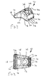
Figure 2 shows a top plan view of the clamp head; -
Figure 3 shows a further perspective view of the clamp head; -
Figure 4 shows a bottom plan view of the clamp head; -
Figure 5 shows a side view of the clamp head; -
Figure 6 shows the cross-sectional view indicated by arrows A-A offigure 5 ; -
Figure 7 shows an end view of the clamp head; -
Figure 8 shows the cross-sectional view indicated by arrows B-B offigure 7 ; -
Figure 9 shows a further end view of the clamp head; -
Figures 10a and 10b show side views of the clamp head relative to a clamping surface; -
Figure 11 shows a side view of a clamp arrangement incorporating two clamp heads according to the present invention; -
Figure 12 shows four clamping arrangements positioned so as to clamp two structural steelwork elements to one another; -
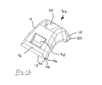
Figure 13 shows a perspective view of an alternative embodiment of a clamp head according to the present invention; and -
Figure 14 shows a perspective view of a further alternative embodiment of a clam head according to the present invention. - Referring to the figures, there is shown a clamp head generally designated 10. The
clamp head 10 is of a unitary construction comprising ashaped body 12. Thebody 12 is preferably manufactured from metal and is formed by a casting, forging or pressing method. As can be seen from the side views, thebody 12 has a generally arched shape having twoarms longer arm 14 may be termed the reaction arm and theshorter arm 16 the clamping arm. The basis for this terminology is described in greater detail below. As can be further be seen from the side views, thebody 12 is at its thickest at thevertex 26 of the arch and at its thinnest at thedistal ends arms body 12 may be considered to have an upper side orface 28 and a lower side orface 30. The radius of curvature of thevertex 26 on both the upper andlower sides body 12 is greater than the respective radii of curvature of thedistal ends arms - The top and bottom plan views show that the
body 12 has a generally tapered shape which is at its widest at thedistal end 18 of thereaction arm 14, and at its narrowest at the opposingdistal end 20 of theclamping arm 16. Theaforementioned distal ends arms - The
distal end 18 of thereaction arm 14 is rounded and is provided with a plurality ofridges 22. Theridges 22 are interspersed betweenrespective troughs 24. Theridges 22 andtroughs 24 extend transversely across thedistal end 18 of thereaction arm 14 and partially around the rounded end of thereaction arm 14 in the region of thelower side 30 of thebody 12. The crowns of theridges 22 may be considered to constitute reaction faces of theclamp 10 as, in use, the crowns rest against a reaction surface as will be described below. Theridges 22 andtroughs 24 extend fully across thedistal end 18 of thereaction arm 14. As such, thedistal end 18 of thereaction arm 14 can bridge slots or apertures 25 (seefigure 9 ) of asurface 27 upon which reaction arm rests, with the opposing ends of theridges 22 andtroughs 24 engaging thesurface 27. - The
distal end 20 of theclamping arm 16 is also rounded and provided with a plurality ofteeth 32. Theteeth 32 are interspersed byspaces 34. Theteeth 32 andspaces 34 are aligned with thelongitudinal axis 80 of thebody 12 such that theridges 22 andtroughs 24 of thereaction arm 14 extend in a direction which is substantially perpendicular to that of the teeth andspaces teeth 32 may be considered to constitute clamping faces of theclamp 10 as, in use, the crown surfaces rest against a clamping surface as will be described in greater detail below. Theridges 22 andteeth 32 additionally, in use, resist rotation of theclamp head 10 as indicated byarrow 58 offigure 2 , - The
body 12 is further provided with athrough aperture 36 which extends through thebody 12 between the upper andlower sides aperture 36 tapers outwardly in the direction of thelower side 30 of thebody 12. Theaperture 36 is not circular, but instead is oval. Thelower side 30 of thebody 12 is further provided with arecess 38 which extends between the reaction arm side of theaperture 36 and thedistal end 18 of thereaction arm 14. Theupper side 28 of thebody 12 is further provided with arecess 48 around the upper side end of theaperture 36 and over thevertex 26 of the arch. Therecess 48 does not extend fully over the length or width of the body and as such a longitudinally extendingcurved wall aperture 36. Thewalls floor 46 of therecess 48. - The presence of the
recess 48 on theupper side 28 of thebody 12 is optional. Where arecess 48 is provided in theupper side 28 of theclamp head 10, and the installation requirements of theclamp head 10 specify that arecess 48 not be provided, then a curved insert (not shown) conforming to the shape and size of therecess 48 may be utilised to "fill in" therecess 48. The insert is provided with a through aperture which aligns with theaperture 36 of thebody 12. - Referring now to
figures 10a and 10b , theclamp head 10 is shown resting upon areaction surface 50. Infigure 10a both thereaction arm 14 and the clampingarm 16 rest upon thereaction surface 50. Infigure 10b thereaction arm 14 rests upon thereaction surface 50, while the clampingarm 16 rests upon a clampingsurface 52.Broken lines 54 indicate the centreline of a fastener, such as a bolt, passing through theaperture 36 of the clamp head. It will be understood that force applied to theclamp head 10 through the fastener as indicated by arrows 60 is transmitted to the reaction and clampingsurfaces arms aperture 36 in theupper side 28 of thebody 12, together with the outwardly tapering shape of theaperture 36 through thebody 12 in the direction of thelower side 30 ensures that the shank of the bolt does not come into contact with the interior surface of theaperture 36. This enables theclamp head 10 to accommodate a range of clamping distances, which is to say the distance between thereaction surface 50 and the clampingsurface 52 as indicated by arrow 56. Theridges 22 andteeth 34 of thearms surfaces clamp head 10. Theclamp head 10 of the present invention can this be utilised for a range of clamping distances where previously, a range of different clamp heads would need to be provided. -
Figures 11 and 12 show a plurality of clamp arrangements, generally designated 64, having two clamp heads 10 joined by a nut and bolt 66,68. The clamp heads 10 are of the type without therecess 48 in theupper surface 28. Theclamp arrangements 64 are mounted to aplate 70 which is provided between two "I" section beams 72. The clamp heads 10 are arranged such that the clampingarms 16 rest against flanges of thebeams 72, while thereaction arms 14 rest against theplate 70. -
Figures 13 and14 show alternative embodiments of a clamp head according to the present invention and designated 74 and 76 respectively. Features common to theclamp 10 described with reference tofigures 1 to 10b are identified with like reference numerals. Thebody 12 of theclamp head 74 is shown with a substantially smoothupper side 28. Theclamp head 74 is provided with asmall recess 78 in on thereaction arm 14, but does not have thelonger recess 48 orwalls figures 1 to 10b . Theclamp head 76 offigure 14 is provided with thewalls longer recess 48 of the clamp described with reference tofigures 1 to 10b .
Claims (18)
- A clamp head comprising an arched body having upper and lower faces, a vertex and opposing unequal length arms, the body further having a through aperture for a bolt or like threaded fastener extending between the upper and lower faces in the region of the vertex, the aperture in the upper face being oval and tapering outwardly through the body in the direction of the lower face, wherein the arms comprise a reaction arm having at its distal end a reaction portion and a clamping arm having at its distal end a clamping portion, the reaction and clamping portions being provided with respective formations, and wherein the formations of the reaction arm extend in a direction which is substantially transverse to the direction of the formations of the clamping arm.
- A clamp head as claimed in claim 1 wherein the formations of the reaction arm extend in a direction substantially perpendicular to the direction of the formations of the clamping arm.
- A clamp head as claimed in claim 1 or claim 2 wherein the formations of the reaction arm extend in a direction substantially transverse to a longitudinal axis of the clamp head.
- A clamp head as claimed in claim 3 wherein the formations of the clamping arm extend in a direction substantially parallel to a longitudinal axis of the clamp head.
- A clamp head as claimed in any preceding claim wherein the reaction arm is longer than the clamping arm.
- A clamp head as claimed in any preceding claim wherein the reaction arm widens in the direction of the distal end of the reaction arm.
- A clamp head as claimed in any preceding claim wherein the clamping arm narrows in the direction of the distal end of the clamping arm.
- A clamp head as claimed in any of claims I to 5 wherein the reaction arm widens in the direction of the distal end of the reaction arm and the clamping arm narrows in the direction of the distal end of the clamping arm.
- A clamp head as claimed in claim 8 wherein the distal end of the clamping arm is narrower than the distal end of the reaction arm.
- A clamp head as claimed in any preceding claim wherein the formations of the reaction arm comprise at least one ridge and at least one trough which extend across the reaction portion of the reaction arm from one side of the reaction arm to the other.
- A clamp head as claimed in claim 10 wherein the reaction arm is provided with a plurality of ridges and troughs.
- A clamp head as claimed in claim 11 wherein the reaction portion of the reaction arm is rounded and the plurality of ridges and troughs are spaced around the rounded reaction portion.
- A clamp head as claimed in any preceding claim wherein the formations of the clamping portion comprise a plurality of teeth.
- A clamp head as claimed in any preceding claim wherein the upper surface of the body is adapted to capture the flat sides of a nut or bolt head to prevent rotation thereof.
- A clamp head as claimed in claim 14 wherein the upper face of the arched body in the region of the vertex and through aperture is provided with abutments against which the flat sides of a nut or bolt head can, in use, engage.
- A clamp head as claimed in claim 15 wherein the upper face of the arched body is recessed between said abutments.
- A clamp arrangement including a clamp head according to any preceding claim, the clamp arrangement having an elongate threaded fastener such as a nut and bolt extending through the through aperture of the or each clamp head.
- A clamp arrangement as claimed in claim 17 wherein the clamp arrangement includes a further clamp head according to any preceding claim, said further clamp head being provided on the elongate threaded fastener and opposing the first clamp head.
Applications Claiming Priority (1)
| Application Number | Priority Date | Filing Date | Title |
|---|---|---|---|
| GB0700818A GB0700818D0 (en) | 2007-01-16 | 2007-01-16 | Clamp head |
Publications (2)
| Publication Number | Publication Date |
|---|---|
| EP1946891A1 true EP1946891A1 (en) | 2008-07-23 |
| EP1946891B1 EP1946891B1 (en) | 2010-10-20 |
Family
ID=37810034
Family Applications (1)
| Application Number | Title | Priority Date | Filing Date |
|---|---|---|---|
| EP20080033505 Active EP1946891B1 (en) | 2007-01-16 | 2008-01-14 | Clamp head |
Country Status (7)
| Country | Link |
|---|---|
| US (1) | US8459624B2 (en) |
| EP (1) | EP1946891B1 (en) |
| AT (1) | ATE485131T1 (en) |
| AU (1) | AU2008200182B2 (en) |
| CA (1) | CA2618413C (en) |
| DE (1) | DE602008003036D1 (en) |
| GB (1) | GB0700818D0 (en) |
Cited By (3)
| Publication number | Priority date | Publication date | Assignee | Title |
|---|---|---|---|---|
| GB2501960A (en) * | 2012-12-30 | 2013-11-13 | Mark Iain Gillies Cottrell | Thatch fixing device |
| WO2014053868A1 (en) | 2012-10-01 | 2014-04-10 | Ev Ip Lp | Improved clamp head |
| USD762436S1 (en) | 2015-04-09 | 2016-08-02 | Ev Ip Lp | Clamp head |
Families Citing this family (6)
| Publication number | Priority date | Publication date | Assignee | Title |
|---|---|---|---|---|
| AU2010241246B2 (en) * | 2010-01-21 | 2014-12-04 | Pierre Camilleri | Building frame |
| CN102975055B (en) * | 2011-09-07 | 2015-03-18 | 朱华丰 | Mold press plate |
| ES2637944T3 (en) * | 2014-06-06 | 2017-10-18 | MTU Aero Engines AG | Arrangement of the components of a gas turbine |
| EP3228833B1 (en) | 2016-04-05 | 2018-08-01 | MTU Aero Engines GmbH | Connection assembly for components made of ceramic fiber composite materials of an intermediate turbine housing |
| US10857638B2 (en) * | 2017-08-16 | 2020-12-08 | Michael W Stark | Vise clamp |
| CN218674263U (en) * | 2022-11-24 | 2023-03-21 | 深圳市道通科技股份有限公司 | Calibration disc, calibration equipment and calibration system |
Citations (6)
| Publication number | Priority date | Publication date | Assignee | Title |
|---|---|---|---|---|
| US2175453A (en) | 1938-01-24 | 1939-10-10 | T B F Company | Clamp |
| DE2106205A1 (en) * | 1971-02-10 | 1972-08-24 | Steinmueller Gmbh L & C | Clamping element |
| US4289059A (en) * | 1978-07-24 | 1981-09-15 | Henry Lindsay Limited | Hook bolt adapter |
| EP0431209A1 (en) * | 1989-12-06 | 1991-06-12 | Erico Gmbh | Device for clamping rails or the like |
| DE9207874U1 (en) * | 1991-06-11 | 1992-09-03 | Pommier & Cie, Saint-Ouen L'aumone, Val D'oise | Clamping jaw with automatic positioning |
| EP1249621A2 (en) * | 2001-04-12 | 2002-10-16 | Lisega Gmbh | Device for clamping supports |
Family Cites Families (12)
| Publication number | Priority date | Publication date | Assignee | Title |
|---|---|---|---|---|
| GB483121A (en) * | 1937-07-14 | 1938-04-12 | Henry Lindsay | Improvements in or relating to hook adapters for bolts, applicable also for clampinggirders and the like together |
| US3338520A (en) * | 1965-08-16 | 1967-08-29 | Charles C Dinger | Rail anchor |
| US3552649A (en) * | 1968-08-23 | 1971-01-05 | Rails Co The | Railroad bridge tie anchor |
| GB2042617A (en) | 1978-12-29 | 1980-09-24 | Midland Gratings Ltd | Clamps |
| US4432538A (en) * | 1981-11-30 | 1984-02-21 | Hector Sequin | Machine tool clamp |
| US4819869A (en) * | 1987-03-05 | 1989-04-11 | Matlock Gordon E | Toggle tie plate fastening system |
| US5096118A (en) * | 1987-03-05 | 1992-03-17 | Matlock Gordon E | Toggle tie plate rail fastening system |
| US5451116A (en) * | 1992-06-09 | 1995-09-19 | General Electric Company | Tripod plate for turbine flowpath |
| US6010121A (en) * | 1999-04-21 | 2000-01-04 | Lee; Chi Ping | Work piece clamping device of workbench |
| DE29915435U1 (en) * | 1999-09-03 | 2001-01-18 | Halfen GmbH & Co. Kommanditgesellschaft, 40764 Langenfeld | Beam clamp |
| DE20114346U1 (en) | 2001-08-30 | 2002-10-02 | Halfen GmbH & Co. Kommanditgesellschaft, 40764 Langenfeld | Beam clamp |
| USD597393S1 (en) * | 2007-01-16 | 2009-08-04 | Ev Ip Lp | Clamp head |
-
2007
- 2007-01-16 GB GB0700818A patent/GB0700818D0/en not_active Ceased
-
2008
- 2008-01-14 AT AT08033505T patent/ATE485131T1/en not_active IP Right Cessation
- 2008-01-14 AU AU2008200182A patent/AU2008200182B2/en active Active
- 2008-01-14 EP EP20080033505 patent/EP1946891B1/en active Active
- 2008-01-14 DE DE200860003036 patent/DE602008003036D1/en active Active
- 2008-01-16 CA CA 2618413 patent/CA2618413C/en active Active
- 2008-09-05 US US12/205,782 patent/US8459624B2/en active Active
Patent Citations (6)
| Publication number | Priority date | Publication date | Assignee | Title |
|---|---|---|---|---|
| US2175453A (en) | 1938-01-24 | 1939-10-10 | T B F Company | Clamp |
| DE2106205A1 (en) * | 1971-02-10 | 1972-08-24 | Steinmueller Gmbh L & C | Clamping element |
| US4289059A (en) * | 1978-07-24 | 1981-09-15 | Henry Lindsay Limited | Hook bolt adapter |
| EP0431209A1 (en) * | 1989-12-06 | 1991-06-12 | Erico Gmbh | Device for clamping rails or the like |
| DE9207874U1 (en) * | 1991-06-11 | 1992-09-03 | Pommier & Cie, Saint-Ouen L'aumone, Val D'oise | Clamping jaw with automatic positioning |
| EP1249621A2 (en) * | 2001-04-12 | 2002-10-16 | Lisega Gmbh | Device for clamping supports |
Cited By (6)
| Publication number | Priority date | Publication date | Assignee | Title |
|---|---|---|---|---|
| WO2014053868A1 (en) | 2012-10-01 | 2014-04-10 | Ev Ip Lp | Improved clamp head |
| US20150266165A1 (en) * | 2012-10-01 | 2015-09-24 | Ev Ip Lp | Clamp Head |
| US9597780B2 (en) | 2012-10-01 | 2017-03-21 | Ev Ip Lp | Clamp head |
| GB2501960A (en) * | 2012-12-30 | 2013-11-13 | Mark Iain Gillies Cottrell | Thatch fixing device |
| GB2501960B (en) * | 2012-12-30 | 2014-05-07 | Mark Iain Gillies Cottrell | Thatch fixing |
| USD762436S1 (en) | 2015-04-09 | 2016-08-02 | Ev Ip Lp | Clamp head |
Also Published As
| Publication number | Publication date |
|---|---|
| ATE485131T1 (en) | 2010-11-15 |
| CA2618413A1 (en) | 2008-07-16 |
| EP1946891B1 (en) | 2010-10-20 |
| AU2008200182A1 (en) | 2008-07-31 |
| US20090051093A1 (en) | 2009-02-26 |
| US8459624B2 (en) | 2013-06-11 |
| GB0700818D0 (en) | 2007-02-21 |
| CA2618413C (en) | 2014-10-07 |
| AU2008200182B2 (en) | 2013-12-12 |
| DE602008003036D1 (en) | 2010-12-02 |
Similar Documents
| Publication | Publication Date | Title |
|---|---|---|
| CA2618413C (en) | Clamp head | |
| CN106049689B (en) | Anchor rail for anchoring in concrete | |
| JP5961678B2 (en) | Beam connection device | |
| CN101779052A (en) | Stud for securing a splice strap to an end of a conveyor belt and stud-and-strap assembly | |
| US11013941B2 (en) | Device for preventing persons from falling | |
| EP2924186B1 (en) | Building connection with nail plate hanger with bendable tab | |
| US10443230B2 (en) | Composite deck fastener | |
| JP2011069155A (en) | Fixation metal fitting | |
| US9597780B2 (en) | Clamp head | |
| JP6407062B2 (en) | Gondola guide rail mounting bracket and mounting structure | |
| JP5178943B1 (en) | Connecting tool for rod-shaped members such as reinforcing bars | |
| JP5057356B2 (en) | Corrugated asbestos slate roof remodeling method | |
| JP3138891U (en) | Steel wire rope clamp | |
| EP1834099B1 (en) | Clamp head | |
| JP5276033B2 (en) | Fasteners | |
| JP2018523585A (en) | Torque Wrench | |
| JP2007186941A5 (en) | ||
| CN218118261U (en) | Dovetail tooth anti-skidding T-shaped bolt | |
| JP4230987B2 (en) | Rope crossing fastener | |
| JP6792775B2 (en) | Reinforcing bar | |
| JP6590989B1 (en) | Safety belt attachment | |
| JP4657101B2 (en) | Base material connecting structure and joining auxiliary member for the base material connecting structure | |
| JP2006177046A (en) | Load transmission parts for anchoring prestressed concrete tension member, and prestressed concrete structure using the same | |
| JP2007284933A (en) | Metal fitting for adjusting length of chain | |
| JP2004176285A (en) | Form clamp |
Legal Events
| Date | Code | Title | Description |
|---|---|---|---|
| PUAI | Public reference made under article 153(3) epc to a published international application that has entered the european phase |
Free format text: ORIGINAL CODE: 0009012 |
|
| AK | Designated contracting states |
Kind code of ref document: A1 Designated state(s): AT BE BG CH CY CZ DE DK EE ES FI FR GB GR HR HU IE IS IT LI LT LU LV MC MT NL NO PL PT RO SE SI SK TR |
|
| AX | Request for extension of the european patent |
Extension state: AL BA MK RS |
|
| 17P | Request for examination filed |
Effective date: 20090122 |
|
| 17Q | First examination report despatched |
Effective date: 20090227 |
|
| AKX | Designation fees paid |
Designated state(s): AT BE BG CH CY CZ DE DK EE ES FI FR GB GR HR HU IE IS IT LI LT LU LV MC MT NL NO PL PT RO SE SI SK TR |
|
| RAP1 | Party data changed (applicant data changed or rights of an application transferred) |
Owner name: EV IP LP |
|
| 111L | Licence recorded |
Free format text: 0101 LIDGET LLP Effective date: 20090511 |
|
| GRAP | Despatch of communication of intention to grant a patent |
Free format text: ORIGINAL CODE: EPIDOSNIGR1 |
|
| RIN1 | Information on inventor provided before grant (corrected) |
Inventor name: GASKELL, MARK Inventor name: FOSTER, LOUISE Inventor name: KLIPPEL, SIMON Inventor name: GILL, NEIL FRANK |
|
| RIN1 | Information on inventor provided before grant (corrected) |
Inventor name: KLIPPEL, SIMON Inventor name: GILL, NEIL FRANK Inventor name: FOSTER, LOUISE Inventor name: GASKELL, MARK |
|
| GRAS | Grant fee paid |
Free format text: ORIGINAL CODE: EPIDOSNIGR3 |
|
| GRAA | (expected) grant |
Free format text: ORIGINAL CODE: 0009210 |
|
| AK | Designated contracting states |
Kind code of ref document: B1 Designated state(s): AT BE BG CH CY CZ DE DK EE ES FI FR GB GR HR HU IE IS IT LI LT LU LV MC MT NL NO PL PT RO SE SI SK TR |
|
| REG | Reference to a national code |
Ref country code: GB Ref legal event code: FG4D |
|
| REG | Reference to a national code |
Ref country code: CH Ref legal event code: EP Ref country code: CH Ref legal event code: PK Free format text: ERGAENZUNG LIZENZEINTRAG: NICHT AUSSCHLIESSLICHE LIZENZ |
|
| REG | Reference to a national code |
Ref country code: IE Ref legal event code: FG4D |
|
| REF | Corresponds to: |
Ref document number: 602008003036 Country of ref document: DE Date of ref document: 20101202 Kind code of ref document: P |
|
| REG | Reference to a national code |
Ref country code: NL Ref legal event code: VDEP Effective date: 20101020 |
|
| LTIE | Lt: invalidation of european patent or patent extension |
Effective date: 20101020 |
|
| PG25 | Lapsed in a contracting state [announced via postgrant information from national office to epo] |
Ref country code: LT Free format text: LAPSE BECAUSE OF FAILURE TO SUBMIT A TRANSLATION OF THE DESCRIPTION OR TO PAY THE FEE WITHIN THE PRESCRIBED TIME-LIMIT Effective date: 20101020 Ref country code: NO Free format text: LAPSE BECAUSE OF FAILURE TO SUBMIT A TRANSLATION OF THE DESCRIPTION OR TO PAY THE FEE WITHIN THE PRESCRIBED TIME-LIMIT Effective date: 20110120 |
|
| PG25 | Lapsed in a contracting state [announced via postgrant information from national office to epo] |
Ref country code: HR Free format text: LAPSE BECAUSE OF FAILURE TO SUBMIT A TRANSLATION OF THE DESCRIPTION OR TO PAY THE FEE WITHIN THE PRESCRIBED TIME-LIMIT Effective date: 20101020 Ref country code: SI Free format text: LAPSE BECAUSE OF FAILURE TO SUBMIT A TRANSLATION OF THE DESCRIPTION OR TO PAY THE FEE WITHIN THE PRESCRIBED TIME-LIMIT Effective date: 20101020 Ref country code: LV Free format text: LAPSE BECAUSE OF FAILURE TO SUBMIT A TRANSLATION OF THE DESCRIPTION OR TO PAY THE FEE WITHIN THE PRESCRIBED TIME-LIMIT Effective date: 20101020 Ref country code: AT Free format text: LAPSE BECAUSE OF FAILURE TO SUBMIT A TRANSLATION OF THE DESCRIPTION OR TO PAY THE FEE WITHIN THE PRESCRIBED TIME-LIMIT Effective date: 20101020 Ref country code: FI Free format text: LAPSE BECAUSE OF FAILURE TO SUBMIT A TRANSLATION OF THE DESCRIPTION OR TO PAY THE FEE WITHIN THE PRESCRIBED TIME-LIMIT Effective date: 20101020 Ref country code: BG Free format text: LAPSE BECAUSE OF FAILURE TO SUBMIT A TRANSLATION OF THE DESCRIPTION OR TO PAY THE FEE WITHIN THE PRESCRIBED TIME-LIMIT Effective date: 20110120 Ref country code: PT Free format text: LAPSE BECAUSE OF FAILURE TO SUBMIT A TRANSLATION OF THE DESCRIPTION OR TO PAY THE FEE WITHIN THE PRESCRIBED TIME-LIMIT Effective date: 20110221 Ref country code: SE Free format text: LAPSE BECAUSE OF FAILURE TO SUBMIT A TRANSLATION OF THE DESCRIPTION OR TO PAY THE FEE WITHIN THE PRESCRIBED TIME-LIMIT Effective date: 20101020 Ref country code: IS Free format text: LAPSE BECAUSE OF FAILURE TO SUBMIT A TRANSLATION OF THE DESCRIPTION OR TO PAY THE FEE WITHIN THE PRESCRIBED TIME-LIMIT Effective date: 20110220 Ref country code: NL Free format text: LAPSE BECAUSE OF FAILURE TO SUBMIT A TRANSLATION OF THE DESCRIPTION OR TO PAY THE FEE WITHIN THE PRESCRIBED TIME-LIMIT Effective date: 20101020 |
|
| PG25 | Lapsed in a contracting state [announced via postgrant information from national office to epo] |
Ref country code: BE Free format text: LAPSE BECAUSE OF FAILURE TO SUBMIT A TRANSLATION OF THE DESCRIPTION OR TO PAY THE FEE WITHIN THE PRESCRIBED TIME-LIMIT Effective date: 20101020 Ref country code: GR Free format text: LAPSE BECAUSE OF FAILURE TO SUBMIT A TRANSLATION OF THE DESCRIPTION OR TO PAY THE FEE WITHIN THE PRESCRIBED TIME-LIMIT Effective date: 20110121 |
|
| PG25 | Lapsed in a contracting state [announced via postgrant information from national office to epo] |
Ref country code: EE Free format text: LAPSE BECAUSE OF FAILURE TO SUBMIT A TRANSLATION OF THE DESCRIPTION OR TO PAY THE FEE WITHIN THE PRESCRIBED TIME-LIMIT Effective date: 20101020 Ref country code: CZ Free format text: LAPSE BECAUSE OF FAILURE TO SUBMIT A TRANSLATION OF THE DESCRIPTION OR TO PAY THE FEE WITHIN THE PRESCRIBED TIME-LIMIT Effective date: 20101020 Ref country code: ES Free format text: LAPSE BECAUSE OF FAILURE TO SUBMIT A TRANSLATION OF THE DESCRIPTION OR TO PAY THE FEE WITHIN THE PRESCRIBED TIME-LIMIT Effective date: 20110131 |
|
| PLBE | No opposition filed within time limit |
Free format text: ORIGINAL CODE: 0009261 |
|
| STAA | Information on the status of an ep patent application or granted ep patent |
Free format text: STATUS: NO OPPOSITION FILED WITHIN TIME LIMIT |
|
| PG25 | Lapsed in a contracting state [announced via postgrant information from national office to epo] |
Ref country code: DK Free format text: LAPSE BECAUSE OF FAILURE TO SUBMIT A TRANSLATION OF THE DESCRIPTION OR TO PAY THE FEE WITHIN THE PRESCRIBED TIME-LIMIT Effective date: 20101020 Ref country code: MC Free format text: LAPSE BECAUSE OF NON-PAYMENT OF DUE FEES Effective date: 20110131 Ref country code: PL Free format text: LAPSE BECAUSE OF FAILURE TO SUBMIT A TRANSLATION OF THE DESCRIPTION OR TO PAY THE FEE WITHIN THE PRESCRIBED TIME-LIMIT Effective date: 20101020 Ref country code: SK Free format text: LAPSE BECAUSE OF FAILURE TO SUBMIT A TRANSLATION OF THE DESCRIPTION OR TO PAY THE FEE WITHIN THE PRESCRIBED TIME-LIMIT Effective date: 20101020 Ref country code: RO Free format text: LAPSE BECAUSE OF FAILURE TO SUBMIT A TRANSLATION OF THE DESCRIPTION OR TO PAY THE FEE WITHIN THE PRESCRIBED TIME-LIMIT Effective date: 20101020 |
|
| 26N | No opposition filed |
Effective date: 20110721 |
|
| REG | Reference to a national code |
Ref country code: DE Ref legal event code: R097 Ref document number: 602008003036 Country of ref document: DE Effective date: 20110721 |
|
| PG25 | Lapsed in a contracting state [announced via postgrant information from national office to epo] |
Ref country code: MT Free format text: LAPSE BECAUSE OF FAILURE TO SUBMIT A TRANSLATION OF THE DESCRIPTION OR TO PAY THE FEE WITHIN THE PRESCRIBED TIME-LIMIT Effective date: 20101020 Ref country code: IT Free format text: LAPSE BECAUSE OF FAILURE TO SUBMIT A TRANSLATION OF THE DESCRIPTION OR TO PAY THE FEE WITHIN THE PRESCRIBED TIME-LIMIT Effective date: 20101020 |
|
| REG | Reference to a national code |
Ref country code: CH Ref legal event code: PL |
|
| PG25 | Lapsed in a contracting state [announced via postgrant information from national office to epo] |
Ref country code: CH Free format text: LAPSE BECAUSE OF NON-PAYMENT OF DUE FEES Effective date: 20120131 Ref country code: LI Free format text: LAPSE BECAUSE OF NON-PAYMENT OF DUE FEES Effective date: 20120131 |
|
| PG25 | Lapsed in a contracting state [announced via postgrant information from national office to epo] |
Ref country code: LU Free format text: LAPSE BECAUSE OF NON-PAYMENT OF DUE FEES Effective date: 20110114 Ref country code: CY Free format text: LAPSE BECAUSE OF FAILURE TO SUBMIT A TRANSLATION OF THE DESCRIPTION OR TO PAY THE FEE WITHIN THE PRESCRIBED TIME-LIMIT Effective date: 20101020 |
|
| PG25 | Lapsed in a contracting state [announced via postgrant information from national office to epo] |
Ref country code: TR Free format text: LAPSE BECAUSE OF FAILURE TO SUBMIT A TRANSLATION OF THE DESCRIPTION OR TO PAY THE FEE WITHIN THE PRESCRIBED TIME-LIMIT Effective date: 20101020 |
|
| PG25 | Lapsed in a contracting state [announced via postgrant information from national office to epo] |
Ref country code: HU Free format text: LAPSE BECAUSE OF FAILURE TO SUBMIT A TRANSLATION OF THE DESCRIPTION OR TO PAY THE FEE WITHIN THE PRESCRIBED TIME-LIMIT Effective date: 20101020 |
|
| REG | Reference to a national code |
Ref country code: FR Ref legal event code: PLFP Year of fee payment: 8 |
|
| REG | Reference to a national code |
Ref country code: FR Ref legal event code: PLFP Year of fee payment: 9 |
|
| REG | Reference to a national code |
Ref country code: FR Ref legal event code: PLFP Year of fee payment: 10 |
|
| REG | Reference to a national code |
Ref country code: FR Ref legal event code: PLFP Year of fee payment: 11 |
|
| REG | Reference to a national code |
Ref country code: DE Ref legal event code: R082 Ref document number: 602008003036 Country of ref document: DE Representative=s name: 4IP GLEIMPETRI PATENT- UND RECHTSANWALTSPARTNE, DE |
|
| PGFP | Annual fee paid to national office [announced via postgrant information from national office to epo] |
Ref country code: GB Payment date: 20260116 Year of fee payment: 19 |
|
| PGFP | Annual fee paid to national office [announced via postgrant information from national office to epo] |
Ref country code: DE Payment date: 20260121 Year of fee payment: 19 Ref country code: IE Payment date: 20260122 Year of fee payment: 19 |
|
| PGFP | Annual fee paid to national office [announced via postgrant information from national office to epo] |
Ref country code: FR Payment date: 20260123 Year of fee payment: 19 |