JP2007186941A5 - - Google Patents
Download PDFInfo
- Publication number
- JP2007186941A5 JP2007186941A5 JP2006006955A JP2006006955A JP2007186941A5 JP 2007186941 A5 JP2007186941 A5 JP 2007186941A5 JP 2006006955 A JP2006006955 A JP 2006006955A JP 2006006955 A JP2006006955 A JP 2006006955A JP 2007186941 A5 JP2007186941 A5 JP 2007186941A5
- Authority
- JP
- Japan
- Prior art keywords
- new
- old
- horizontal member
- roof
- screw
- Prior art date
- Legal status (The legal status is an assumption and is not a legal conclusion. Google has not performed a legal analysis and makes no representation as to the accuracy of the status listed.)
- Granted
Links
- 239000010425 asbestos Substances 0.000 description 41
- 229910052895 riebeckite Inorganic materials 0.000 description 41
- 239000010454 slate Substances 0.000 description 35
- 240000005511 Pisonia aculeata Species 0.000 description 14
- 239000002184 metal Substances 0.000 description 11
- 229910000831 Steel Inorganic materials 0.000 description 10
- 239000010959 steel Substances 0.000 description 10
- 230000001808 coupling Effects 0.000 description 8
- 238000010168 coupling process Methods 0.000 description 8
- 238000005859 coupling reaction Methods 0.000 description 8
- 239000000789 fastener Substances 0.000 description 8
- 239000000463 material Substances 0.000 description 7
- 210000000614 Ribs Anatomy 0.000 description 4
- 230000002093 peripheral Effects 0.000 description 3
- 238000007634 remodeling Methods 0.000 description 3
- 238000009418 renovation Methods 0.000 description 3
- 238000005452 bending Methods 0.000 description 2
- 241000221535 Pucciniales Species 0.000 description 1
- 238000010276 construction Methods 0.000 description 1
- 238000005553 drilling Methods 0.000 description 1
- 230000000694 effects Effects 0.000 description 1
- 238000000034 method Methods 0.000 description 1
- 238000000465 moulding Methods 0.000 description 1
- 238000005096 rolling process Methods 0.000 description 1
- 239000007787 solid Substances 0.000 description 1
- 230000000087 stabilizing Effects 0.000 description 1
- 238000005728 strengthening Methods 0.000 description 1
- 238000009864 tensile test Methods 0.000 description 1
- 238000003466 welding Methods 0.000 description 1
Images

Description
この発明は、古くなった旧石綿スレート屋根をそのままにしてその上にさらに石綿を含まない新しいスレート屋根または折板屋根等を葺くための波形石綿スレートの屋根リフォーム工法に関する。 The present invention relates to a corrugated asbestos slate roof remodeling method for leaving an old asbestos slate roof as it is, and further rolling a new slate roof or a folded-plate roof or the like that does not contain asbestos.
スレート屋根には、従来一般的に、C型鋼を屋根に横架材として架設し、それにフックボルトで波形石綿スレートを止める葺き方が多く、その波形石綿スレートの屋根が朽ちて残存しているのが現状である。従来、これが朽ちたときには、修繕して改善し、あるいは撤去して新たに屋根を構築していたが、波形石綿スレートの成形材料にアスベストが30%も使用されているのが問題となっており、工事中にアスベストが飛散する危険を防止するために、飛散が生じると考えられる穴あけ、撤去、溶接などの作業が禁じられるようになった。 Conventionally, there are many ways to slate roofs that have C-shaped steel installed on the roof as horizontal members, and to stop the corrugated asbestos slate with hook bolts, and the corrugated asbestos slate roof has decayed and remains. Is the current situation. Conventionally, when this decayed, it was repaired and improved, or it was removed and a new roof was constructed. However, asbestos is used as a molding material for corrugated asbestos slate as a problem. In order to prevent the risk of asbestos scattering during construction, drilling, removal, welding, etc., which are thought to cause scattering, are prohibited.
波形石綿スレートが葺かれている構造については、図2に示すように、屋根に横架材11としてのC型鋼が開口面を下向きに架設されており、波形石綿スレート13にはその波形頂部においてフックボルト17の通し穴を明け、通し穴にフックボルトを差し込んで下端のフックがC型鋼の開口縁に引っかけられ、波形石綿スレート13の上においてフックボルトの軸に上下可能に取り付けられる笠パッキン23をナット21の締め付けで押し下げることにより、フックの引っ掛かりが外れないよう保持されている。したがって、波形石綿スレート13の山部の上端にはフックボルト17の雄ねじ25が笠パッキン23やナット21とともに露出している。
As for the structure in which the corrugated asbestos slate is spread, as shown in FIG. 2, the C-shaped steel as the
しかし、葺き替えの時期になると、フックボルトの上端の雄ねじが錆びついて、ナットを外すことができなくなっていることが多く、そうすると、波形石綿スレートを撤去するときには、C型鋼からフックボルトを外すために、フックボルトを強く押し下げ時には打ち叩くことになるために、波形石綿スレートに無理な力が加わってそれが破壊し、破壊口からアスベストが飛散する危険を招く。また、外した波形石綿スレートを屋根から乱暴に落下させるとさらにアスベストの飛散が多く生じる危険もある。 However, when it comes time to replace the hook bolt, the male screw at the top end of the hook bolt rusts and it is often impossible to remove the nut. Then, when removing the corrugated asbestos slate, it is necessary to remove the hook bolt from the C-shaped steel. Since the hook bolt is struck when it is pressed down, an excessive force is applied to the corrugated asbestos slate, causing it to break down, resulting in the risk of asbestos scattering from the destruction port. Also, if the corrugated asbestos slate is dropped from the roof, there is a risk that more asbestos will be scattered.
この発明は、上記のような実情に鑑みて、波形石綿スレートで葺かれる旧屋根はそのままにしておいて、その上に石綿を含まない新しい波形スレート(または他の波形屋根板や折板屋根)を葺くことにして、この新屋根板の構築の基材としてのC型鋼からなる新横架材を安定して強力に架設できる波形石綿スレートの屋根リフォーム工法を提供することを課題とした。 In view of the above circumstances, the present invention leaves the old roof made of corrugated asbestos slate as it is, and a new corrugated slate that does not contain asbestos (or other corrugated roof or folded sheet roof). The object of the present invention is to provide a corrugated asbestos slate roof renovation method capable of stably and powerfully laying a new horizontal member made of C-shaped steel as a base material for constructing the new roof plate.
この発明は、上記の課題を解決するため、C形鋼からなる旧横架材に旧フックボルトを掛け、その笠パッキンを旧ナットで締めることにより波形石綿スレートが葺かれている旧屋根の上に、石綿の含まない新屋根板で葺かれる新屋根を構築するために、旧横架材の上方に別のC形鋼の新横架材を基材として架設し、新横架材の架設について、それと波形石綿スレートとの間に、その山部を跨ぐ左右一対の脚部片と新横架材の結合体とを備えた頂部支持金物を介在させ、頂部支持金物を旧フックボルトの軸の上端に形成されている前記旧ナット締め用の雄ねじに、雌雄ねじ形の割りねじを螺着するともに締め金具で固着し、頂部支持金物の中心を貫通した割りねじの上端に新ナットを螺入して締め付けることにより、新横架材が支持されるよう頂部支持金物を固定することを特徴とする波形石綿スレートの屋根リフォーム工法を提供するものである。 In order to solve the above-mentioned problems, the present invention is provided on an old roof on which corrugated asbestos slate is spread by hanging an old hook bolt on an old horizontal member made of C-shaped steel and fastening its cap packing with an old nut. In order to construct a new roof that is covered with a new roof plate that does not contain asbestos, a new horizontal member made of another C-shaped steel is installed above the old horizontal member as a base material, and a new horizontal member is installed. The top support hardware provided with a pair of left and right leg pieces and a new horizontal member straddling the mountain portion between the corrugated asbestos slate and the top support hardware is attached to the shaft of the old hook bolt. A female male thread type split screw is screwed to the male screw for tightening the old nut formed at the upper end of the nut and fixed with a fastener, and a new nut is screwed onto the upper end of the split screw that penetrates the center of the top support hardware. Insert and tighten to support the new horizontal member There is provided a roof renovation method of waveform asbestos slate, characterized in that to fix the parts supporting hardware.
波形石綿スレートの屋根リフォーム工法を上記のように構成したから、新横架材を支持する頂部支持金物が波形石綿スレートの山部を脚部片で跨いて取り付けられ、しかも、古くなって朽ちている旧フックボルトの雄ねじには、新たに割りねじが螺着されるとともに締め金具で固定して取り付けられ、割りねじにナットを螺合して締め付けることにより、頂部支持金物が安定して固定されるため、新屋根板を葺く基材としての新横架材を強力に支持することができる。 Since the corrugated asbestos slate roof remodeling method is constructed as described above, the top support hardware that supports the new horizontal member is attached across the mountain part of the corrugated asbestos slate with leg pieces, and it becomes old and decays. A new split screw is screwed onto the male thread of the old hook bolt and fixed with a fastener, and the top support hardware is stably fixed by screwing the nut into the split screw and tightening. Therefore, it is possible to strongly support the new horizontal member as a base material on which the new roof plate is spread.
以上説明したように、この発明によれば、波形石綿スレートで葺かれている旧屋根はそのままにしてその上に新屋根板を葺くために、アスベストが飛散するような作業を省くことができ安全であり、しかも、旧屋根の旧フックボルトの雄ねじが錆びついていても、それを軸にして新たなねじを作り、それにナットを螺合して締め付けることにより、頂部支持金物を強固に取り付け、それに新横架材を架設することにより、アスベストが含まない新屋根板を簡単にしかも安定して葺くことができるという優れた効果がある。 As described above, according to the present invention, it is possible to omit the work of asbestos scattering in order to spread the new roof board on the old roof that has been rolled with corrugated asbestos slate. Even if the male screw of the old hook bolt of the old roof is rusted, it is safe, and a new screw is made with it as a shaft, and a nut is screwed into it and tightened to firmly attach the top support hardware, In addition, by installing a new horizontal member, there is an excellent effect that a new roof plate not containing asbestos can be easily and stably spread.
また、請求項2および3の如くにすると、新横架材をさらに安定して支持でき、しかも、作業手順も良好である。 Further, according to the second and third aspects, the new horizontal member can be supported more stably, and the work procedure is good.
次に、この発明の実施形態を図面に基づいて説明する。 Next, embodiments of the present invention will be described with reference to the drawings.
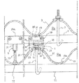
図面は一実施の形態を示したもので、その波形石綿スレートの屋根リフォーム工法は、既存の旧屋根Raはそのままにして、その上に新屋根Rbが構築され、波形石綿スレート13の山部に配列される頂部支持金物1と、複数の頂部支持金物1で受けられる新横架材2と、新横架材2の上に葺かれる新屋根板3とが用いられる。この新屋根板3には石綿の入っていない波形スレートが用いられ、それが新横架材2に新フックボルト7で止められる。また、頂部支持金物1と頂部支持金物1との間の中間において、補助的に底部支持金物5が用いられる。
The drawing shows an embodiment, and the roof remodeling method of the corrugated asbestos slate is such that the existing old roof Ra is left as it is, and a new roof Rb is constructed on it, and the
旧屋根Raは、旧横架材11の上に波形石綿スレート13を載置し、その頂部に有する抜け穴15に旧フックボルト17を差し込んでフックを旧横架材11に掛け、上端の雄ねじ25に旧ナット21を締めることにより、その下の笠パッキン23を抜け穴15の周縁部に圧接させてある。旧フックボルト17は、35年〜40年経過しているため、旧ナット21が螺入される雄ねじ25が錆びついている。しかし、この旧フックボルト17の使用適正について、富山県工業技術センターでその引っ張り試験を行ったところ、その試験結果から表1に示す通り、「フック部の曲がり」と「ねじ部からのフックの抜け」について、十分な強度を有することが分かった。
In the old roof Ra, the
表1の記載のうち、「ねじ部からのフックの抜け」については、後記するように、錆びた旧フックボルト17の雄ねじ25に、割りねじ31を螺着し、締め金具33で締め付けた状態において、「その割りねじ31からのフックボルト17の抜け」の最大荷重において雄ねじ25に対する割りねじ31の引っ張り強度を示したが、当初予想していたよりも2〜3倍の強度アップであって、むしろフックの方が先に折れることもあった。
Among the descriptions in Table 1, “disengagement of the hook from the screw portion” is a state in which the

旧横架材11および新横架材2にはC型鋼が用いられ、いずれも断面開口を下向きにして、旧横架材11は建物の梁等の間に架設されるが、新横架材2は配列される複数の頂部支持金物1,1,・・の上に架設され、頂部支持金物1が旧横架材11に掛かる旧フックボルト17に取り付けられるので、新横架材2は旧横架材11の丁度上に配置されることになる。しかし、支持箇所が波形石綿スレート13の山部に限られるので、後記するように、旧横架材11が真下となるしっかりした基盤の谷部において頂部支持金物1を反り部37a,37aで支持させることに加えて、谷部に底部支持金物5が配置される。
The old
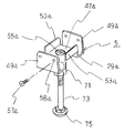
頂部支持金物1は、波形石綿スレート13の波に載る金物本体27と、その頂部に嵌まる結合体29と、旧フックボルト17の雄ねじ25に嵌める割りねじ31と、割りねじ31の締め金具33と、割りねじ31に螺入する新ナット34とからなる。
The
そのうち、金物本体27は、帯鋼板に曲げ加工を施すことにより成形され、波形石綿スレート13の山頂に位置する起立部35を中央として、それから左右にそれぞれ山に沿って下るとともに隣接山に沿って少し反り上がる形状の脚部片37,37が連設されたもので、両反り部37a,37aがあるために、金物本体27が傾く不都合が一層防止されるだけでなく、前記の如く、脚部片37,37が旧横架材11にそのまま(空間なしに)支持される。しかも、脚部片37,37には幅中央に沿って隆起リブ38,38が形成されているため、その支持は確実に上端に及ぶ。
Among them, the hardware
金物本体27の起立部35は、上端が偏平で二股の屈折形状であるが、前記両反り部37a,37aやリブ38,38があるために開拡が阻止される安定性がある。上端面には割りねじ31の通し溝穴39が横方向に長く設けられている。また、起立部35の上部において、通し溝穴39の幅方向の両側端において切欠41,41が設けられ、その分だけ起立部35の幅が狭くなる頭部43が形成される。こうすると、切欠41,41で受けられるため結合体29が傾かないようにスライド可能に安定して頭部43に嵌まっている。この結合体29のスライドは、中央の通し穴55を下の前記通し溝穴39に沿って位置調整するためで、これによって、フックボルト17の雄ねじ25の位置に予期しない誤差があっても、割りねじ31を通し穴55に通し、新ナット34で締め付け得る状態が得られる。
The
結合体29は、鋼板を曲げ加工することにより形成され、上記のように頭部43に嵌まる逆チャンネル形の断面形状の嵌合央部47を基体として、その前後両側下端にはL字形の屈折側部片49,49が連設される。新横架材2は、嵌合央部47に被嵌されることにより、屈折側部片49,49の起立部間に挟持されるとともに、その下端の基部で受け止められる。また、嵌合央部47の左右両端には、新横架材2の中に深く突入する起立片53,53が突設され、中央部には割りねじ31の通し穴55が新ナット34が掛かる大きさに形成される。なお、起立片53,53は、新横架材2との結合を安定化させることのほかに嵌合央部47のリブとしての作用を果たす。また、屈折側部片49,49には、一対ずつビス57,57の通し穴58,58が設けられ、最終的には、新横架材2にビスをねじ込んでそれが結合体29に固定される。
The
割りねじ31は、筒形の内周面に旧フックボルト17の雄ねじ25に螺合する雌ねじを、外周面には新ナット34が螺合する雄ねじがそれぞれ形成される雌雄両ねじ形であって、下端部に割り溝59を設けたもので、締め金具33は、割り溝59の箇所で割りねじ31を絞ることにより旧フックボルト17の雄ねじ25との結合を強化するようにしたものである。
The
締め金具33の構造については、割りねじ31に囲むように嵌まる割り筒形であって、割り筒形の開口両端に相対面し先端が屈折して支点として噛み合う締め片61,62が突設され、両締め片61,62にボルト63の通し穴65を設け、ナット67で締めつけるようにしたもので、一方の締め片61の両側にはボルト63の四角頭部の回転を止め得るように掛かるリブ兼用の係合縁69,69が形成される。これにより、結合体29をスライドにより位置調整しながら、結合体29の通し穴55と通し溝穴39に割りねじ31を通すとともに、旧フックボルト17の雄ねじ25に締め金具33により割りねじ31を固定し、割りねじ31に対する新ナット34の締め付けが結合体29の上においてなされる。
The structure of the
頂部支持金物1と頂部支持金物1との間の中間部において新横架材2を補助的に受けるために、波形石綿スレート13の谷部に底部支持金物5が配設されている。その底部支持金物5には、新横架材2の結合体29aが用いられ、それは頂部支持金物1のうちの結合体29と同じ形状であって、結合体29aの中央に長ナットの雌ねじ71を溶接して垂設し、それに支持ボルト73を螺入して取り付けたもので、支持ボルト73の下端には頭部としての足部75が波形石綿スレート13の谷部に(旧横架材11との接触箇所に)当たりやすく円形(丸形)に形成される。そこで、頂部支持金物1で新横架材2を架設した後で、波形石綿スレート13の谷部において、新横架材2に下から結合体29aを差し込み、支持ボルト73のねじでの長さ調整により下端の足部75を波形石綿スレート13の谷部に圧接させることにより、新横架材2を強固な旧横架材11に直接的に支持する体勢とすることができる。
In order to supplementarily receive the new
結合体29aは、頂部支持金物1の結合体29と同じであるが、ちなみに形状について説明すると、新横架材2の開口部に嵌まる逆チャンネル形の断面形状の嵌合央部47aを基体として、そのチャンネル形の両側下端にはL字形の屈折側部片49a,49aが連設される。新横架材2との関係では、それが嵌合央部47aに嵌まることにより、屈折側部片49a,49aのL字形起立部間に挟持されるとともに、下端の基部で受けられる。また、嵌合央部47aの左右両端には、新横架材2の中に深く突入する起立片53a,53aが突設され、中央部には支持ボルト73の通し穴55aが形成される。また、屈折側部片49a,49aには、新横架材2との結合強化のため一対ずつビス57a,57aの通し穴58a,58aが設けられる。
The combined
Ra 旧屋根
Rb 新屋根
1 頂部支持金物
2 新横架材
3 新屋根板
5 底部支持金物
11 旧横架材
13 波形石綿スレート
17 旧フックボルト
21 旧ナット
23 笠パッキン
25 雄ねじ
27 金物本体
29 結合体
29a 結合体
31 割りねじ
33 締め金具
34 新ナット
35 起立部
37 脚部片
37a 反り部
39 通し溝穴
43 頭部
47 嵌合央部
49 屈折側部片
53 起立片
55 通し穴
61,62 締め片
63 ボルト
67 ナット
71 雌ねじ
73 支持ボルト
75 足部
Ra Old roof
34
Priority Applications (1)
| Application Number | Priority Date | Filing Date | Title |
|---|---|---|---|
| JP2006006955A JP5057356B2 (en) | 2006-01-16 | 2006-01-16 | Corrugated asbestos slate roof remodeling method |
Applications Claiming Priority (1)
| Application Number | Priority Date | Filing Date | Title |
|---|---|---|---|
| JP2006006955A JP5057356B2 (en) | 2006-01-16 | 2006-01-16 | Corrugated asbestos slate roof remodeling method |
Publications (3)
| Publication Number | Publication Date |
|---|---|
| JP2007186941A JP2007186941A (en) | 2007-07-26 |
| JP2007186941A5 true JP2007186941A5 (en) | 2009-04-02 |
| JP5057356B2 JP5057356B2 (en) | 2012-10-24 |
Family
ID=38342287
Family Applications (1)
| Application Number | Title | Priority Date | Filing Date |
|---|---|---|---|
| JP2006006955A Expired - Fee Related JP5057356B2 (en) | 2006-01-16 | 2006-01-16 | Corrugated asbestos slate roof remodeling method |
Country Status (1)
| Country | Link |
|---|---|
| JP (1) | JP5057356B2 (en) |
Families Citing this family (6)
| Publication number | Priority date | Publication date | Assignee | Title |
|---|---|---|---|---|
| JP5124773B2 (en) * | 2007-10-09 | 2013-01-23 | Jfe鋼板株式会社 | Repair structure of slate roof and its repair method |
| JP5232998B2 (en) * | 2009-12-11 | 2013-07-10 | Jfe鋼板株式会社 | Roof plate holding metal fittings for repairing slate roofs, repair structures for slate roofs and repair methods |
| JP5222868B2 (en) * | 2010-02-23 | 2013-06-26 | 株式会社オーティス | Roof mounting fixture |
| JP5588730B2 (en) * | 2010-04-28 | 2014-09-10 | 株式会社オーティス | Mounting structure for roof mounting fixture |
| JP2012158977A (en) * | 2012-04-18 | 2012-08-23 | Jfe Galvanizing & Coating Co Ltd | Slate-covered roof repairing clamp fitting |
| CN106760230A (en) * | 2016-12-30 | 2017-05-31 | 安徽马钢工程技术集团有限公司 | A kind of roofing color steel tile structure and its installation method |
Family Cites Families (4)
| Publication number | Priority date | Publication date | Assignee | Title |
|---|---|---|---|---|
| JP2002349531A (en) * | 2001-05-25 | 2002-12-04 | Daiwa House Ind Co Ltd | Nut member |
| JP3809100B2 (en) * | 2001-12-13 | 2006-08-16 | 日鉄鋼板株式会社 | Exterior material replacement jig and exterior material replacement structure |
| JP3959279B2 (en) * | 2002-01-30 | 2007-08-15 | 日本植生株式会社 | Fastening device for rod-shaped member |
| JP2004076516A (en) * | 2002-08-22 | 2004-03-11 | Dokoo:Kk | Fixing device of discoid body |
-
2006
- 2006-01-16 JP JP2006006955A patent/JP5057356B2/en not_active Expired - Fee Related
Similar Documents
| Publication | Publication Date | Title |
|---|---|---|
| JP5057356B2 (en) | Corrugated asbestos slate roof remodeling method | |
| JP2007186941A5 (en) | ||
| KR101557419B1 (en) | A deck having reinforcement for preventing distortion of deck edge and deck install structure using the same | |
| JP4446353B2 (en) | Suspension bolt support bracket for shape steel | |
| JP5156153B2 (en) | Arrangement body support | |
| JP4807832B2 (en) | Scaffold plate support bracket | |
| JP6050022B2 (en) | Building fixture | |
| JP5551530B2 (en) | Joint sealing material and its mounting structure | |
| JP6085826B2 (en) | Exterior structure renovation metal fitting and its transfer member, projecting portion fixing member, exterior structure refurbishment structure | |
| JP5302662B2 (en) | Deck material mounting structure | |
| JP3577238B2 (en) | Roof replacement structure | |
| JP2010047911A (en) | Method for repairing roof | |
| JP6864547B2 (en) | Eaves inspection corridor | |
| JP5619043B2 (en) | Roof mounting fixture | |
| JP2004108069A (en) | Exterior material reroofing tool and exterior material reroofing structure | |
| JP2017078303A (en) | Gutter | |
| JP2001279875A (en) | Method and structure for repairing roof and metal clamp fitting for repairing roof used in the same | |
| JP7158250B2 (en) | Fixing structure for building members | |
| JP5232998B2 (en) | Roof plate holding metal fittings for repairing slate roofs, repair structures for slate roofs and repair methods | |
| JP2010138569A (en) | Clip for roof renovating construction method | |
| JPH0315701Y2 (en) | ||
| JPS5929060Y2 (en) | anti-slip for buildings | |
| JP3484630B2 (en) | Double-roofed roof structure | |
| JP6171236B2 (en) | Support metal fittings for descending roof tiles | |
| JPH0111869Y2 (en) |