EP2903699B1 - Nasal filter - Google Patents
Nasal filter Download PDFInfo
- Publication number
- EP2903699B1 EP2903699B1 EP13845501.9A EP13845501A EP2903699B1 EP 2903699 B1 EP2903699 B1 EP 2903699B1 EP 13845501 A EP13845501 A EP 13845501A EP 2903699 B1 EP2903699 B1 EP 2903699B1
- Authority
- EP
- European Patent Office
- Prior art keywords
- lateral
- medial
- nose
- support section
- filter
- Prior art date
- Legal status (The legal status is an assumption and is not a legal conclusion. Google has not performed a legal analysis and makes no representation as to the accuracy of the status listed.)
- Active
Links
- 241000083547 Columella Species 0.000 claims description 10
- 230000008859 change Effects 0.000 claims description 9
- 210000000845 cartilage Anatomy 0.000 claims description 4
- 210000001331 nose Anatomy 0.000 description 67
- 239000000463 material Substances 0.000 description 24
- 238000001914 filtration Methods 0.000 description 14
- 239000002245 particle Substances 0.000 description 11
- 210000003928 nasal cavity Anatomy 0.000 description 8
- 238000005452 bending Methods 0.000 description 6
- 230000008901 benefit Effects 0.000 description 5
- 239000010410 layer Substances 0.000 description 5
- 230000029058 respiratory gaseous exchange Effects 0.000 description 4
- 230000007246 mechanism Effects 0.000 description 3
- 238000000034 method Methods 0.000 description 3
- 229920000642 polymer Polymers 0.000 description 3
- 238000009826 distribution Methods 0.000 description 2
- 239000002861 polymer material Substances 0.000 description 2
- 229920001296 polysiloxane Polymers 0.000 description 2
- 210000003625 skull Anatomy 0.000 description 2
- 238000001179 sorption measurement Methods 0.000 description 2
- 229920002725 thermoplastic elastomer Polymers 0.000 description 2
- 230000007704 transition Effects 0.000 description 2
- 241000743339 Agrostis Species 0.000 description 1
- 206010013975 Dyspnoeas Diseases 0.000 description 1
- 238000004026 adhesive bonding Methods 0.000 description 1
- 208000026935 allergic disease Diseases 0.000 description 1
- 210000000621 bronchi Anatomy 0.000 description 1
- 238000005266 casting Methods 0.000 description 1
- 239000000428 dust Substances 0.000 description 1
- 230000000694 effects Effects 0.000 description 1
- 239000004744 fabric Substances 0.000 description 1
- 230000001815 facial effect Effects 0.000 description 1
- 229920005570 flexible polymer Polymers 0.000 description 1
- 239000006261 foam material Substances 0.000 description 1
- 210000003128 head Anatomy 0.000 description 1
- 238000002844 melting Methods 0.000 description 1
- 230000008018 melting Effects 0.000 description 1
- 210000004379 membrane Anatomy 0.000 description 1
- 239000012528 membrane Substances 0.000 description 1
- 210000002850 nasal mucosa Anatomy 0.000 description 1
- 239000004745 nonwoven fabric Substances 0.000 description 1
- 230000008569 process Effects 0.000 description 1
- 210000002345 respiratory system Anatomy 0.000 description 1
- 238000007873 sieving Methods 0.000 description 1
- 239000002356 single layer Substances 0.000 description 1
- 239000012780 transparent material Substances 0.000 description 1
- 238000003466 welding Methods 0.000 description 1
Images


Classifications
-
- A—HUMAN NECESSITIES
- A62—LIFE-SAVING; FIRE-FIGHTING
- A62B—DEVICES, APPARATUS OR METHODS FOR LIFE-SAVING
- A62B23/00—Filters for breathing-protection purposes
- A62B23/06—Nose filters
-
- A—HUMAN NECESSITIES
- A62—LIFE-SAVING; FIRE-FIGHTING
- A62B—DEVICES, APPARATUS OR METHODS FOR LIFE-SAVING
- A62B7/00—Respiratory apparatus
- A62B7/10—Respiratory apparatus with filter elements
Definitions
- the present invention relates to nasal filters of the type with a frame onto which a filter is attached, for example a planar filter. Especially, it relates to a nasal filter comprising a frame with a right and a left frame portion dimensioned for placement inside a right and left nostril, for example connected via a U-shaped bridge.
- the vertical central wall of the nose between the left and right nostril is typically called the medial wall or septum of the nose and ends at the low end of the nose, which is called the columella.
- the nostrils are largely delimited by the septum and the lateral parts, which are the outer wings of the nostrils, bending from the edge of the septum at the tip of the nose to the back edge of the septum near the head skeleton.
- the forward direction towards the tip of the nose is termed anterior and the back of the nose towards the skull is termed posterior.
- Personal air filtering devices can be divided into two main categories: facial masks that cover both mouth and nose and nasal filters that solely cover the nose.
- Nasal filters can be sub-divided into externally placed nasal filters and internally placed nasal filters.
- Many nasal filters have one filter unit for each nostril, the filter units being connected via a U-formed, flexible bridge that clips around the columella of the nose and holds the filter units in place inside the nostrils.
- the filter units are often elongate with a longitudinal direction and a transverse direction; when inserted into the nose, the longitudinal direction of the filter extends from the anterior part of the nostril at the tip of the nose to the posterior part of the nostril near the skull, and the transverse direction extends from the septum of the nose to the lateral part of the nose.
- Substantially flat filter type devices are disclosed in Canadian patent application CA26589940 , British patent application GB2289846 , German patent laid open document DE3914606A1 , Japanese patent application JP2002-345986A , German utility model DE202010001203U1 , US patents and applications US2046664 , US228268 , US5392773 , US7156099 , US2007/0283963 , US2008/0087286 , US2012/0111334 , and International patent applications WO2005/120645 , WO2009/097553 , and WO2011/041921 .
- an internal nasal filter In order for an internal nasal filter to work well, be acceptable and attractive to the user in daily life, it must fulfil some basic objectives: It must be near to invisible, it must allow adequate air movement without a steep increase in resistance while breathing, it most remove what it is claiming to remove, it must be able to accommodate a variety of nasal sizes and shapes, it must substantially follow the curvature of the nasal cavity so that all inhaled air passes through the filtration mechanism, and finally it must be comfortable to wear.
- cone-like structures The primary drawback of cone-like structures is generally the sheer mass of material that has to be placed in the nasal cavity. This increases visibility of the filter; lowers the available space for airflow, thus, increasing resistance; and feels uncomfortable for users, thus, lowering compliance.
- European Patent EP2089115B1 describes an internal nasal filter comprising lunette-shaped filtering components on an oval support that is connected to a flexible U-shaped bridge that functions as a clip around the lower edge of the cartilage of the nose.
- the ends of the flexible U-shaped element (from hereon referred to as shanks) are placed substantially perpendicular to the flexible U-shaped element. This results in the shanks and the filter being perpendicular to the air stream, which makes sense from a filtration perspective. However, it also results in increased resistance as the shanks are placed in the primary air stream thus resulting in laboured breathing. Furthermore the angle at which the shanks are placed and their solidity results in discomfort when touching or moving the nose.
- EP2089115B1 utilises the idea of using the more flexible filtering components to adjust for different nose sizes and variations, the embodiments of its shanks lack the ability to uphold a filtering component without internal stiffness. This results in discomfort because of the necessary stiff structural characteristics of the filtering components and their perpendicular angle to the nasal canal. It also results in gaps along the curvature of the nasal cavity through which unfiltered air is inhaled.
- anterior or “posterior” are used for those parts that are configured to be placed towards the anterior or posterior part of the nostril.
- medial and lateral are used for those parts of the nasal filter that are directed towards the medial part or lateral part of the nose, respectively.
- a reference plane can be defined for the frame as follows.
- the anterior support section of each frame portion has a frontal point configured for being directed towards the front of the nose when the nasal filter is inserted into a nose; and the posterior support section of each frame portion has a backmost point configured for being directed towards the back of the nose when the nasal filter is inserted into a nose; due to symmetry, these two frontal points and the two backmost points in common define a reference plane.
- This reference plane is also uniquely defined by a normal vector perpendicular to the reference plane.
- the medial resilient member comprises a medial bend to provide a resilient connection between the medial sector and the medial segment.
- This bend exists when the nasal filter is in a relaxed state.
- this medial bend extends outside the filter support plane.
- the medial bend is directed substantially downwards, and has a bottom, when the nasal filter is inserted into a nose.
- the bottom of a bend can be defined as that point within the bend that has the largest distance to the reference plane.
- the medial bend extends largely perpendicular to the reference plane, for example within plus or minus 20 degrees from the normal of the reference plane.
- the direction of the radius of curvature at the bottom of the bend is largely perpendicular to the reference plane, where the term largely perpendicular means within 20 degrees with the normal vector, for example within 10 or 5 degrees with the normal vector.
- this substantially vertical arrangement of the medial bend is advantageous in that the medial bend acts as a medial spring between the anterior and posterior support section.
- the medial side is planar and parallel to a symmetry plane between the two frame portions, the angle is measured from this symmetry plane.
- the lateral bend is directed upward or is a combination of a downwards bend and an upwards bend; optionally, within the same angular interval.
- the posterior support section has a downward slope in the direction from the medial sector towards the lateral sector, where the downward slope forms an angle of 45-85 degrees to the normal of the reference plane.
- the downward slope forms an angle of 5-45 degrees with a plane parallel to the symmetry plane between the right and left frame portions.
- the useful material is made of polymer fibres distributed randomly in a horizontal plane and sequentially deposited on top of each other to build a structure with a thickness of between 0.05 mm and 1 mm, advantageously between 0.07 and 0.2 mm.
- the diameters of the fibres are between 15 and 30 micron, the fibres being considered mono-diameter fibres.
- the material contains on average 5-18 fibres stacked in the height direction, although it is pointed out that the number of stacked fibres varies greatly because of the random distribution.
- the distance between two fibres, which are level in a horizontal plane, is mainly between 0.05 and 0.4 mm.
- the overall mesh sizes of the material vary greatly depending on the distance between individual fibres in the same horizontal plan and the random distribution of fibres in the levels above and below the individual fibres. In general the average mesh size is larger than the diameter of the particles that the material is filtering.
- the weight of the material is advantageously between 5 and 40 g/m2.
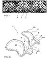
- FIG. 1 shows a photograph of some prototypes in various sizes of a nasal filter 1, the nasal filter having a frame 2 and a filter element 3 attached to the frame 2.
- FIG. 2a is a perspective view of one embodiment of a frame 2 of a nasal filter.
- the frame 2 comprises a U-formed bridge 4 connecting the medial sides of a left frame portion 2a and a right frame portion 2b.
- the bridge 4 acts as a clip, or part of a clip, around the columella of the nose.
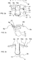
- FIG. 2b, 2c, and 2d are different perspectives of the same frame as in FIG. 2a , namely a view from the front, side, and back, respectively.
- Each of the frame portions 2a, 2b comprises a support section 6 and a connector 7 connecting the bridge 4 with the support section 6.
- the support section 6 is that part of the frame 2 that supports the filter element 3.
- the bridge 4 acts as a clip around the columella of the nose; or the bridge 4 in combination with the connector 7 acts as a clip around the columella of the nose.
- the bridge 4 and the connector 7 are those parts of the frame 2 that clip around the cartilage of the septum and, when in use by a standing person, extend upwards and inwards along the septum of the nose.
- the support section 6 is arranged to support the filter element 3 that extends across the nostril. Typically, the support section 6 extends across the nostril or surrounds the nostril along the nostril wall in order to support the filter element 3.
- the support section 6 defines a plane for the filter element, actually a convex, bent plane. Alternatively, the plane could be straight or concavely bent. With reference to the embodiment of FIG. 1 , it is seen that the area spanned by the support section 6 is designed to be smaller than the area of the filter element 3 such that the support section 6 does not necessarily touch the inner walls of the nostrils during use of the nasal filter 1, however, the filter element would touch the inner wall of the nostrils when the nasal filter is in proper use. The fact that the filter material extends outside the support section 6 is not strictly necessary but usually is more comfortable.
- the support section 6 comprises an anterior support section 6a that supports the filter element 3 at the anterior part of the nostril, and the support section 6 has a posterior support section 6b that supports the filter element 3 at the posterior part of the nostril.
- the anterior support section 6a adjusts to different noses and guides the device into its correct position by being flexible due to the resilient means described in more detail in the following.
- a reference plane 23 is referred to as illustrated in FIG. 7 .
- the reference plane 23 is defined by the two frontal points 21a, 21b of the anterior support sections 6a, and the two most backward points 22a, 22b of the posterior support sections 6b.
- the term "downwards direction” is used for a direction perpendicular to the reference plane 23 and is meant to be towards the nose entrance for a normally standing person when using the nasal filter, although it is pointed out that noses differ and downwards does not necessarily mean vertically downwards for a standing person.
- the term “upwards” is used for the opposite direction.
- a direction perpendicular to the reference plane 23 is defined by the normal vector 29 of the reference plane 23, the normal vector 29 defining the orientation of the reference plane 23 in space.
- the anterior support section 6a comprises a medial segment 18a and a lateral segment 18b where the medial segment 18a is near or at the septum, when the nasal filter is inserted into the nose, and the lateral segment 18b is near the lateral wall of the nostril.
- the posterior support section 6b has a medial sector 16a and a lateral sector 16b, where the medial sector 16a is near or at the septum when the nasal filter is inserted into the nose, and the lateral sector 16b is near the lateral wall of the nostril.
- a lateral resilient member 8' is provided, comprising a lateral bend 8 as part of a lateral side of the frame portion 2a, 2b.
- the lateral resilient member 8' with the lateral bent 8 is configured for flexible change of distance between the lateral segment 18b and the lateral sector 16b.
- the lateral bend 8 connects the lateral segment 18b with the lateral sector 16b.
- a medial resilient member 9' is provided comprising a medial bend 9 as part of a medial side of the frame portion 2a, 2b.
- the medial resilient member 9' with the medial bent 9 is configured for flexible change of distance between the medial segment 18a and the medial sector 16a.
- the medial bend 9 connects the medial segment 18a with the medial sector 16a.
- the lateral bend 8 connects the anterior support section 6a and the posterior support section 6b on the lateral side of the frame portion 2a, 2b.
- the medial bend 9 connects the anterior support section 6a and the posterior support section 6b on the medial side of the frame portion 2a, 2b.
- the bends 8, 9 give the support section 6 a high flexibility as compared to a support section that would be formed by a closed ring as disclosed in GB2289846 .
- the concavity of the illustrated lateral bend 8 is shaped predominantly circular, although this regularity is not necessary.
- the illustrated concavity of the medial bend 9 has a predominant V-shape with rounded bottom, although this regularity is not necessary, thus, resembling the advantages of a cone-like structure in terms of stability combined with the minimalism of a flat structure in order to utilise the best of both structures.
- the lateral bend 8 provides a certain degree of flexibility between the anterior support section 6a and the posterior support section 6b and at the same time stability against wobbliness
- the medial bend 9 provides a certain degree of flexibility between the anterior support section 6a and the posterior support section 6b and at the same time stability along the septum.
- the bends 8, 9 result in the filter element 3 being supported only in the front part of the nostril by the anterior support section 6a and in the back part of the nostril by the posterior support section 6b, whereas there is a region between the anterior support section 6a and the posterior support section 6b where the filter element 3 is not supported.
- the effect is a better adjustment of the filter element 3 inside the nose, resulting in a better tightness of the filter element 3 in the nostril. It increases the overall comfort of the device and helps in securing the device along the curvature of the nasal cavity.
- the filter element 3 has a low stiffness and is easily bendable when the frame 2 is inserted into the nose and the anterior support section 6a and the posterior support section 6b are pushed towards each other in order to adjust to the shape of the nostril.
- the depth is defined as follows with reference to FIG. 7 .
- the first point 8a and the second point 8b are defined as the midpoints of the arch having constant curvature.
- the depth of the lateral bend 8 is thus defined as the distance d between the line 25 and the most downward point 8c of the lateral bend 8 when measured along a direction 26 perpendicular to the reference plane 23, which is the direction given by the normal vector 29.
- a distance d is at least 5% and typically between 10% and 30% of the distance D between the foremost point 21b of the anterior support section and the backmost point 22b of the posterior support section.
- the depth d of the lateral bend is typically between 10% and 30% of the length D of the frame portion 2a,b that is placed in the nose.
- the depth is much larger, typically, between 10% and 80% of the length of the frame portion 2a,b.
- the upper surface 6a' of the anterior support section 6a and the upper surface 6b' of the posterior support section 6b are mutually angled with a mutual angle V', for example of between 5 and 45 degrees, as it is shown in greater detail in the side view of FIG. 3a .
- V' a mutual angle
- the shape is useful in guiding the user when inserting the nasal filter and placing it in a correct position. It also helps the user in placing the nasal filter correctly along the inner walls of the nostrils, thereby minimising gaps despite the curvature of the nasal cavity.
- the feature also ads to the flexibility of the nasal filter, which is important for comfort experienced by the user and the tightness of the filter element 3 against the inner walls of the nostrils.
- the legs 14 of the U-shaped bridge 4 are typically not perpendicular to the reference plane 23 but have a small angle of less than 90 degrees, advantageously an angle of 0 to 10 or 10 to 20 or 20 to 30, for example 5 to 10 or 5 to 20, degrees with the normal 29 of the reference plane 23.
- Such an angle of around 5 or 10 or 15 degrees from the normal 29 to the reference plane 23 results in a better fit of the frame in the nose.
- the angle is measured from this plane 15'. It may have a direction on either side of this plane 15'.
- FIG. 3b shows a top view of the filter 3 on the support 6.
- the lateral dimensions of the filter element 3 are larger than the area spanned by the support section 6, such that the filter element 3 extends farther towards the walls of the nostrils than the support section 6 in order for the filter element 3 to tighten against the inner walls of the nostrils.
- the filter element extends between 0.5 and 1.5 mm outside the support section 6.
- the larger size of the filter element 3 assists in closing gaps between the frame 2 and the inner walls of the nostrils as to accommodate small nasal cavity variations among people; further, depending on the filtering element, it also increases the tolerance and overall comfort of the embodiment, because it works as a cushioning mechanism.
- the posterior support section 6b has a medial sector 16a and a lateral sector 16b, where the medial sector 16a is near or at the septum when the nasal filter is inserted into the nose and the lateral sector 16b is near the lateral wall of the nostril.
- the posterior support section 6b has a downward slope in the direction from the medial sector 16a towards the lateral sector 16b. This downward slope is typically 45-85 degrees, for example in the range of 70-80 degrees, relatively to the normal 29 of the reference plane 23. This slope increases the flexibility of the device and allows the users to be able to touch their noses without feeling discomfort.
- the anterior support section can be sloped for increasing the comfort.
- FIG. 4 illustrates one possible alternative embodiment, showing the alternative frame 2 from a skew front view.
- the frame 2 comprises only a medial bend 9 and not a lateral bend.
- the anterior support section 6a merges with the posterior support section 6b on the lateral sector 16b of the posterior support section 6b.
- the downwards slope of the support section 6 has a typical angle of 45-85 degrees with the normal vector 29; however, it is more pronounced with a steeper angle from the medial sector 16a to lateral sector 16b than illustrated in the model as shown in FIG. 2d .
- the medial bend 9 assists in flexibility of the frame 2 in the direction from the front to the back of the nostril.
- FIG. 5 illustrates a skew view from the side of a further alternative embodiment of a frame 2 for a nasal filter.
- the frame 2 comprises medial bends 9 but not lateral bends.
- the lateral sector 16b of the posterior support section 6b is not directly connected to the anterior support section 6a but decoupled from the anterior support section 6a.
- the anterior support section 6a has a medial segment 18a configured for placement towards the septum and a lateral segment 18b configured for placement against the lateral inner wall of the nostril.
- the lateral segment 18b of the anterior support section 6a and the lateral sector 16b of the posterior support section 6b are not directly connected but only indirectly through the medial segment 18a, the medial bend 9 and the medial sector 16a.
- a gap 17 is provided between lateral segment 18b of the anterior support section 6a and the lateral sector 16b of the posterior support section 6b.
- lateral segment 18b of the anterior support section 6a has a first end 19 and the lateral sector 16b of the posterior support section 6b has a second end 20 on either side of the gap 17.
- the open structure provided by the disconnection between the anterior support section 6a and the posterior support section 6b on the lateral side of the frame portion provides flexibility and adaptability for the frame 2.
- FIG. 6 shows a series of frames with different sizes graphically superimposed on each other.
- the constructed image illustrates that, in these embodiments, the shapes of the frames are not directly scaled, but the shapes of the frames are adjusted according to the size.
- the medial sector 16a of the posterior support section 6b has a different shape in dependence on the size of the frame 2.
- the medial sector 16a bends relatively more outwards for the larger frames than for the smaller frames.
- the angle between the lateral sides of the two frame portions 2a, 2b is larger for the larger models than for the smaller.
- FIG. 8 illustrates an embodiment, where the lateral bend 8 is bending upwards, whereas the medial bend 9 is bending downwards. Only the right frame portion 2b is shown for reasons of simplicity. In this case, it may be advantageous that the filter element is within the frame and does not extend outside the frame.
- the filter element is advantageously a woven or non-woven mesh type filter.
Landscapes
- Health & Medical Sciences (AREA)
- Otolaryngology (AREA)
- General Health & Medical Sciences (AREA)
- Business, Economics & Management (AREA)
- Emergency Management (AREA)
- Respiratory Apparatuses And Protective Means (AREA)
- Orthopedics, Nursing, And Contraception (AREA)
Applications Claiming Priority (2)
| Application Number | Priority Date | Filing Date | Title |
|---|---|---|---|
| DKPA201200616 | 2012-10-08 | ||
| PCT/DK2013/000066 WO2014056501A1 (en) | 2012-10-08 | 2013-10-07 | Nasal filter |
Publications (3)
| Publication Number | Publication Date |
|---|---|
| EP2903699A1 EP2903699A1 (en) | 2015-08-12 |
| EP2903699A4 EP2903699A4 (en) | 2016-05-25 |
| EP2903699B1 true EP2903699B1 (en) | 2017-11-01 |
Family
ID=50476955
Family Applications (1)
| Application Number | Title | Priority Date | Filing Date |
|---|---|---|---|
| EP13845501.9A Active EP2903699B1 (en) | 2012-10-08 | 2013-10-07 | Nasal filter |
Country Status (11)
| Country | Link |
|---|---|
| US (1) | US10758752B2 (enExample) |
| EP (1) | EP2903699B1 (enExample) |
| JP (1) | JP6247304B2 (enExample) |
| CN (1) | CN104703660B (enExample) |
| AU (1) | AU2013329944B2 (enExample) |
| BR (1) | BR112015007795A2 (enExample) |
| CA (1) | CA2926257A1 (enExample) |
| DK (1) | DK2903699T5 (enExample) |
| ES (1) | ES2657641T3 (enExample) |
| RU (1) | RU2639058C2 (enExample) |
| WO (1) | WO2014056501A1 (enExample) |
Families Citing this family (3)
| Publication number | Priority date | Publication date | Assignee | Title |
|---|---|---|---|---|
| ES2850287A1 (es) * | 2020-02-26 | 2021-08-26 | Musat Florian Iulian | Prótesis nasal |
| WO2021206865A1 (en) | 2020-04-08 | 2021-10-14 | Lin Carol Chia Yuan | Nasal mask and associated filter |
| CN114100006B (zh) * | 2021-11-23 | 2022-08-02 | 常州市第一人民医院 | 鼻腔过敏源过滤器 |
Family Cites Families (31)
| Publication number | Priority date | Publication date | Assignee | Title |
|---|---|---|---|---|
| US2055855A (en) * | 1935-02-25 | 1936-09-29 | Harrison J Weaver | Nasal respirator |
| US2046664A (en) | 1935-11-07 | 1936-07-07 | Nasal Filter Co | Nasal filter |
| US2243360A (en) * | 1938-12-30 | 1941-05-27 | Slatis Abraham | Filter or medicament casing |
| US2198959A (en) * | 1939-06-07 | 1940-04-30 | Hubert E Clarke | Nasal filter |
| US2282681A (en) * | 1939-08-14 | 1942-05-12 | Cha Gobe Company | Nasal filter |
| US4052983A (en) * | 1975-09-04 | 1977-10-11 | Bovender Coy R | Nasal filter |
| DE3914606A1 (de) * | 1989-05-03 | 1990-11-08 | Hella Seidel | Pollenschutzfilter |
| DE8910651U1 (de) | 1989-05-03 | 1989-11-16 | Seidel, Hella, 8000 München | Pollenschutzfilter |
| CN2095679U (zh) | 1991-06-28 | 1992-02-12 | 陈发全 | 防尘鼻罩 |
| US5392773A (en) | 1994-04-13 | 1995-02-28 | Bertrand; Archie A. | Respiratory particulate filter |
| GB9411023D0 (en) * | 1994-06-02 | 1994-07-20 | Hurlin Noreen | Filtration device |
| US5727543A (en) * | 1997-02-07 | 1998-03-17 | Corsaro; Luigi | Nasal breathing device |
| JP2002345986A (ja) * | 2001-05-18 | 2002-12-03 | Takeshi Ri | 鼻マスク |
| JP2002345976A (ja) | 2001-05-25 | 2002-12-03 | Techno Sonic:Kk | イオントフォレーゼ用装置 |
| US8833369B2 (en) | 2004-03-19 | 2014-09-16 | Airware, Inc. | Breathing air filtration devices |
| US7156098B2 (en) * | 2004-03-19 | 2007-01-02 | Dolezal Creative Innovations, Llc | Breathing air filtration system |
| ES2242537B1 (es) * | 2004-04-26 | 2006-12-16 | Salvador Tirado Abullon | Respirador anatomico nasal. |
| ITPN20040040A1 (it) | 2004-06-10 | 2004-09-10 | Simone Corinaldesi | Dispositivo filtrante per le vie respiratorie nasali |
| US7156099B1 (en) | 2004-08-03 | 2007-01-02 | Jenkins Cloytillia M | Nostril filtering system |
| ITTV20040056U1 (it) | 2004-10-20 | 2005-01-20 | Dario Toncelli | Macchina tagliatrice combinata per la lavorazione di materiale in lastra. |
| JP2007021156A (ja) * | 2005-07-19 | 2007-02-01 | Isao Miyagawa | 鼻の花粉侵入防止具 |
| US7354467B2 (en) | 2006-02-21 | 2008-04-08 | Yung-Zhem Chen | Filtering assembly in nasal cavities |
| US20070283963A1 (en) | 2006-06-12 | 2007-12-13 | Sims Guadalupe V | Nose air-filter |
| US20080053448A1 (en) * | 2006-08-31 | 2008-03-06 | Liska Regina B | Nasal filter |
| US20080087286A1 (en) | 2006-10-11 | 2008-04-17 | James Jones | Disposable nasal filter |
| US8110061B2 (en) | 2006-10-31 | 2012-02-07 | Moore Joseph K | Respiratory nasal filter |
| ITMI20062334A1 (it) | 2006-12-05 | 2008-06-06 | Emilio Talmon | Filtro dell'aria per applicazione endonasale |
| WO2011041921A1 (zh) | 2009-10-09 | 2011-04-14 | Wang Lei | 鼻罩 |
| JP2011130843A (ja) | 2009-12-22 | 2011-07-07 | Masayasu Nagao | 鼻孔挿入具 |
| DE202010001203U1 (de) | 2010-01-21 | 2010-05-20 | Vogel, Jörg | Nasenfilter zur Abwehr von Feinstaub |
| JP3159887U (ja) | 2010-03-23 | 2010-06-03 | 株式会社ユタカメイク | 鼻マスク |
-
2013
- 2013-10-07 US US14/434,343 patent/US10758752B2/en active Active
- 2013-10-07 CA CA2926257A patent/CA2926257A1/en not_active Abandoned
- 2013-10-07 EP EP13845501.9A patent/EP2903699B1/en active Active
- 2013-10-07 RU RU2015116596A patent/RU2639058C2/ru active
- 2013-10-07 CN CN201380051697.9A patent/CN104703660B/zh not_active Expired - Fee Related
- 2013-10-07 BR BR112015007795A patent/BR112015007795A2/pt not_active Application Discontinuation
- 2013-10-07 ES ES13845501.9T patent/ES2657641T3/es active Active
- 2013-10-07 WO PCT/DK2013/000066 patent/WO2014056501A1/en not_active Ceased
- 2013-10-07 AU AU2013329944A patent/AU2013329944B2/en not_active Ceased
- 2013-10-07 JP JP2015534913A patent/JP6247304B2/ja not_active Expired - Fee Related
- 2013-10-07 DK DK13845501.9T patent/DK2903699T5/en active
Non-Patent Citations (1)
| Title |
|---|
| None * |
Also Published As
| Publication number | Publication date |
|---|---|
| US10758752B2 (en) | 2020-09-01 |
| CN104703660B (zh) | 2017-07-21 |
| DK2903699T5 (en) | 2018-02-26 |
| JP6247304B2 (ja) | 2017-12-13 |
| CN104703660A (zh) | 2015-06-10 |
| WO2014056501A1 (en) | 2014-04-17 |
| EP2903699A1 (en) | 2015-08-12 |
| EP2903699A4 (en) | 2016-05-25 |
| AU2013329944B2 (en) | 2017-11-23 |
| BR112015007795A2 (pt) | 2017-07-04 |
| ES2657641T3 (es) | 2018-03-06 |
| RU2015116596A (ru) | 2016-11-27 |
| RU2639058C2 (ru) | 2017-12-19 |
| AU2013329944A1 (en) | 2015-04-09 |
| DK2903699T3 (da) | 2018-01-29 |
| CA2926257A1 (en) | 2014-04-17 |
| JP2015535716A (ja) | 2015-12-17 |
| US20150265858A1 (en) | 2015-09-24 |
Similar Documents
| Publication | Publication Date | Title |
|---|---|---|
| JP7493646B2 (ja) | 患者インタフェースおよび該患者インタフェースを形成するための方法 | |
| JP7294998B2 (ja) | 患者インタフェース及び患者インタフェースを形成するための方法 | |
| JP5374586B2 (ja) | 鼻部クッション付きマスク | |
| JP2025078708A (ja) | 患者インタフェースおよび該患者インタフェースを形成するための方法 | |
| ES2928472T3 (es) | Interfaz del paciente | |
| JP6270478B2 (ja) | 自動調節クッションを備える患者インターフェース装置 | |
| US20150320959A1 (en) | Nasal interface and removable pad therefor | |
| JP2015522381A5 (enExample) | ||
| AU2007338372A1 (en) | Nose-dilating device | |
| EP2903699B1 (en) | Nasal filter | |
| CN108135299B (zh) | 一次性口罩 | |
| US10426652B2 (en) | Nasal dilator | |
| JP2018167042A (ja) | 患者インタフェースおよび該患者インタフェースを形成するための方法 | |
| KR20130040211A (ko) | 입체 마스크 | |
| JP7682726B2 (ja) | 患者インタフェースおよび該患者インタフェースを形成するための方法 | |
| KR102713045B1 (ko) | 입체구조를 가지는 마스크 | |
| JP2017203221A (ja) | マスク | |
| JP2024149489A (ja) | 患者インタフェース及び患者インタフェースを形成するための方法 |
Legal Events
| Date | Code | Title | Description |
|---|---|---|---|
| PUAI | Public reference made under article 153(3) epc to a published international application that has entered the european phase |
Free format text: ORIGINAL CODE: 0009012 |
|
| 17P | Request for examination filed |
Effective date: 20150414 |
|
| AK | Designated contracting states |
Kind code of ref document: A1 Designated state(s): AL AT BE BG CH CY CZ DE DK EE ES FI FR GB GR HR HU IE IS IT LI LT LU LV MC MK MT NL NO PL PT RO RS SE SI SK SM TR |
|
| AX | Request for extension of the european patent |
Extension state: BA ME |
|
| DAX | Request for extension of the european patent (deleted) | ||
| RA4 | Supplementary search report drawn up and despatched (corrected) |
Effective date: 20160422 |
|
| RIC1 | Information provided on ipc code assigned before grant |
Ipc: A62B 23/06 20060101AFI20160418BHEP |
|
| GRAP | Despatch of communication of intention to grant a patent |
Free format text: ORIGINAL CODE: EPIDOSNIGR1 |
|
| RIC1 | Information provided on ipc code assigned before grant |
Ipc: A62B 23/06 20060101AFI20170425BHEP |
|
| INTG | Intention to grant announced |
Effective date: 20170601 |
|
| GRAS | Grant fee paid |
Free format text: ORIGINAL CODE: EPIDOSNIGR3 |
|
| GRAA | (expected) grant |
Free format text: ORIGINAL CODE: 0009210 |
|
| AK | Designated contracting states |
Kind code of ref document: B1 Designated state(s): AL AT BE BG CH CY CZ DE DK EE ES FI FR GB GR HR HU IE IS IT LI LT LU LV MC MK MT NL NO PL PT RO RS SE SI SK SM TR |
|
| REG | Reference to a national code |
Ref country code: GB Ref legal event code: FG4D |
|
| REG | Reference to a national code |
Ref country code: CH Ref legal event code: EP Ref country code: AT Ref legal event code: REF Ref document number: 941469 Country of ref document: AT Kind code of ref document: T Effective date: 20171115 |
|
| REG | Reference to a national code |
Ref country code: IE Ref legal event code: FG4D |
|
| REG | Reference to a national code |
Ref country code: DE Ref legal event code: R096 Ref document number: 602013028918 Country of ref document: DE |
|
| REG | Reference to a national code |
Ref country code: DK Ref legal event code: T3 Effective date: 20180125 |
|
| REG | Reference to a national code |
Ref country code: DK Ref legal event code: T5 Effective date: 20180221 |
|
| REG | Reference to a national code |
Ref country code: ES Ref legal event code: FG2A Ref document number: 2657641 Country of ref document: ES Kind code of ref document: T3 Effective date: 20180306 |
|
| REG | Reference to a national code |
Ref country code: NL Ref legal event code: MP Effective date: 20171101 |
|
| REG | Reference to a national code |
Ref country code: LT Ref legal event code: MG4D |
|
| REG | Reference to a national code |
Ref country code: AT Ref legal event code: MK05 Ref document number: 941469 Country of ref document: AT Kind code of ref document: T Effective date: 20171101 |
|
| PG25 | Lapsed in a contracting state [announced via postgrant information from national office to epo] |
Ref country code: SE Free format text: LAPSE BECAUSE OF FAILURE TO SUBMIT A TRANSLATION OF THE DESCRIPTION OR TO PAY THE FEE WITHIN THE PRESCRIBED TIME-LIMIT Effective date: 20171101 Ref country code: LT Free format text: LAPSE BECAUSE OF FAILURE TO SUBMIT A TRANSLATION OF THE DESCRIPTION OR TO PAY THE FEE WITHIN THE PRESCRIBED TIME-LIMIT Effective date: 20171101 Ref country code: NL Free format text: LAPSE BECAUSE OF FAILURE TO SUBMIT A TRANSLATION OF THE DESCRIPTION OR TO PAY THE FEE WITHIN THE PRESCRIBED TIME-LIMIT Effective date: 20171101 Ref country code: NO Free format text: LAPSE BECAUSE OF FAILURE TO SUBMIT A TRANSLATION OF THE DESCRIPTION OR TO PAY THE FEE WITHIN THE PRESCRIBED TIME-LIMIT Effective date: 20180201 Ref country code: FI Free format text: LAPSE BECAUSE OF FAILURE TO SUBMIT A TRANSLATION OF THE DESCRIPTION OR TO PAY THE FEE WITHIN THE PRESCRIBED TIME-LIMIT Effective date: 20171101 |
|
| PG25 | Lapsed in a contracting state [announced via postgrant information from national office to epo] |
Ref country code: IS Free format text: LAPSE BECAUSE OF FAILURE TO SUBMIT A TRANSLATION OF THE DESCRIPTION OR TO PAY THE FEE WITHIN THE PRESCRIBED TIME-LIMIT Effective date: 20180301 Ref country code: BG Free format text: LAPSE BECAUSE OF FAILURE TO SUBMIT A TRANSLATION OF THE DESCRIPTION OR TO PAY THE FEE WITHIN THE PRESCRIBED TIME-LIMIT Effective date: 20180201 Ref country code: RS Free format text: LAPSE BECAUSE OF FAILURE TO SUBMIT A TRANSLATION OF THE DESCRIPTION OR TO PAY THE FEE WITHIN THE PRESCRIBED TIME-LIMIT Effective date: 20171101 Ref country code: GR Free format text: LAPSE BECAUSE OF FAILURE TO SUBMIT A TRANSLATION OF THE DESCRIPTION OR TO PAY THE FEE WITHIN THE PRESCRIBED TIME-LIMIT Effective date: 20180202 Ref country code: LV Free format text: LAPSE BECAUSE OF FAILURE TO SUBMIT A TRANSLATION OF THE DESCRIPTION OR TO PAY THE FEE WITHIN THE PRESCRIBED TIME-LIMIT Effective date: 20171101 Ref country code: AT Free format text: LAPSE BECAUSE OF FAILURE TO SUBMIT A TRANSLATION OF THE DESCRIPTION OR TO PAY THE FEE WITHIN THE PRESCRIBED TIME-LIMIT Effective date: 20171101 Ref country code: HR Free format text: LAPSE BECAUSE OF FAILURE TO SUBMIT A TRANSLATION OF THE DESCRIPTION OR TO PAY THE FEE WITHIN THE PRESCRIBED TIME-LIMIT Effective date: 20171101 |
|
| PG25 | Lapsed in a contracting state [announced via postgrant information from national office to epo] |
Ref country code: CZ Free format text: LAPSE BECAUSE OF FAILURE TO SUBMIT A TRANSLATION OF THE DESCRIPTION OR TO PAY THE FEE WITHIN THE PRESCRIBED TIME-LIMIT Effective date: 20171101 Ref country code: EE Free format text: LAPSE BECAUSE OF FAILURE TO SUBMIT A TRANSLATION OF THE DESCRIPTION OR TO PAY THE FEE WITHIN THE PRESCRIBED TIME-LIMIT Effective date: 20171101 Ref country code: CY Free format text: LAPSE BECAUSE OF FAILURE TO SUBMIT A TRANSLATION OF THE DESCRIPTION OR TO PAY THE FEE WITHIN THE PRESCRIBED TIME-LIMIT Effective date: 20171101 Ref country code: SK Free format text: LAPSE BECAUSE OF FAILURE TO SUBMIT A TRANSLATION OF THE DESCRIPTION OR TO PAY THE FEE WITHIN THE PRESCRIBED TIME-LIMIT Effective date: 20171101 |
|
| REG | Reference to a national code |
Ref country code: DE Ref legal event code: R097 Ref document number: 602013028918 Country of ref document: DE |
|
| PG25 | Lapsed in a contracting state [announced via postgrant information from national office to epo] |
Ref country code: RO Free format text: LAPSE BECAUSE OF FAILURE TO SUBMIT A TRANSLATION OF THE DESCRIPTION OR TO PAY THE FEE WITHIN THE PRESCRIBED TIME-LIMIT Effective date: 20171101 Ref country code: SM Free format text: LAPSE BECAUSE OF FAILURE TO SUBMIT A TRANSLATION OF THE DESCRIPTION OR TO PAY THE FEE WITHIN THE PRESCRIBED TIME-LIMIT Effective date: 20171101 Ref country code: PL Free format text: LAPSE BECAUSE OF FAILURE TO SUBMIT A TRANSLATION OF THE DESCRIPTION OR TO PAY THE FEE WITHIN THE PRESCRIBED TIME-LIMIT Effective date: 20171101 |
|
| PLBE | No opposition filed within time limit |
Free format text: ORIGINAL CODE: 0009261 |
|
| STAA | Information on the status of an ep patent application or granted ep patent |
Free format text: STATUS: NO OPPOSITION FILED WITHIN TIME LIMIT |
|
| 26N | No opposition filed |
Effective date: 20180802 |
|
| REG | Reference to a national code |
Ref country code: FR Ref legal event code: PLFP Year of fee payment: 6 |
|
| PG25 | Lapsed in a contracting state [announced via postgrant information from national office to epo] |
Ref country code: SI Free format text: LAPSE BECAUSE OF FAILURE TO SUBMIT A TRANSLATION OF THE DESCRIPTION OR TO PAY THE FEE WITHIN THE PRESCRIBED TIME-LIMIT Effective date: 20171101 |
|
| REG | Reference to a national code |
Ref country code: CH Ref legal event code: PL |
|
| REG | Reference to a national code |
Ref country code: BE Ref legal event code: MM Effective date: 20181031 |
|
| PG25 | Lapsed in a contracting state [announced via postgrant information from national office to epo] |
Ref country code: LU Free format text: LAPSE BECAUSE OF NON-PAYMENT OF DUE FEES Effective date: 20181007 Ref country code: MC Free format text: LAPSE BECAUSE OF FAILURE TO SUBMIT A TRANSLATION OF THE DESCRIPTION OR TO PAY THE FEE WITHIN THE PRESCRIBED TIME-LIMIT Effective date: 20171101 |
|
| REG | Reference to a national code |
Ref country code: IE Ref legal event code: MM4A |
|
| PG25 | Lapsed in a contracting state [announced via postgrant information from national office to epo] |
Ref country code: BE Free format text: LAPSE BECAUSE OF NON-PAYMENT OF DUE FEES Effective date: 20181031 Ref country code: LI Free format text: LAPSE BECAUSE OF NON-PAYMENT OF DUE FEES Effective date: 20181031 Ref country code: CH Free format text: LAPSE BECAUSE OF NON-PAYMENT OF DUE FEES Effective date: 20181031 |
|
| PG25 | Lapsed in a contracting state [announced via postgrant information from national office to epo] |
Ref country code: IE Free format text: LAPSE BECAUSE OF NON-PAYMENT OF DUE FEES Effective date: 20181007 |
|
| PG25 | Lapsed in a contracting state [announced via postgrant information from national office to epo] |
Ref country code: MT Free format text: LAPSE BECAUSE OF NON-PAYMENT OF DUE FEES Effective date: 20181007 |
|
| PG25 | Lapsed in a contracting state [announced via postgrant information from national office to epo] |
Ref country code: TR Free format text: LAPSE BECAUSE OF FAILURE TO SUBMIT A TRANSLATION OF THE DESCRIPTION OR TO PAY THE FEE WITHIN THE PRESCRIBED TIME-LIMIT Effective date: 20171101 |
|
| PG25 | Lapsed in a contracting state [announced via postgrant information from national office to epo] |
Ref country code: PT Free format text: LAPSE BECAUSE OF FAILURE TO SUBMIT A TRANSLATION OF THE DESCRIPTION OR TO PAY THE FEE WITHIN THE PRESCRIBED TIME-LIMIT Effective date: 20171101 |
|
| PG25 | Lapsed in a contracting state [announced via postgrant information from national office to epo] |
Ref country code: MK Free format text: LAPSE BECAUSE OF NON-PAYMENT OF DUE FEES Effective date: 20171101 Ref country code: HU Free format text: LAPSE BECAUSE OF FAILURE TO SUBMIT A TRANSLATION OF THE DESCRIPTION OR TO PAY THE FEE WITHIN THE PRESCRIBED TIME-LIMIT; INVALID AB INITIO Effective date: 20131007 |
|
| PG25 | Lapsed in a contracting state [announced via postgrant information from national office to epo] |
Ref country code: AL Free format text: LAPSE BECAUSE OF FAILURE TO SUBMIT A TRANSLATION OF THE DESCRIPTION OR TO PAY THE FEE WITHIN THE PRESCRIBED TIME-LIMIT Effective date: 20171101 |
|
| PGFP | Annual fee paid to national office [announced via postgrant information from national office to epo] |
Ref country code: IT Payment date: 20201023 Year of fee payment: 8 Ref country code: DK Payment date: 20201028 Year of fee payment: 8 Ref country code: ES Payment date: 20201103 Year of fee payment: 8 |
|
| REG | Reference to a national code |
Ref country code: DK Ref legal event code: EBP Effective date: 20211031 |
|
| PG25 | Lapsed in a contracting state [announced via postgrant information from national office to epo] |
Ref country code: IT Free format text: LAPSE BECAUSE OF NON-PAYMENT OF DUE FEES Effective date: 20211007 Ref country code: DK Free format text: LAPSE BECAUSE OF NON-PAYMENT OF DUE FEES Effective date: 20211031 |
|
| REG | Reference to a national code |
Ref country code: ES Ref legal event code: FD2A Effective date: 20230210 |
|
| PG25 | Lapsed in a contracting state [announced via postgrant information from national office to epo] |
Ref country code: ES Free format text: LAPSE BECAUSE OF NON-PAYMENT OF DUE FEES Effective date: 20211008 |
|
| P01 | Opt-out of the competence of the unified patent court (upc) registered |
Effective date: 20230522 |
|
| PGFP | Annual fee paid to national office [announced via postgrant information from national office to epo] |
Ref country code: DE Payment date: 20241029 Year of fee payment: 12 |
|
| PGFP | Annual fee paid to national office [announced via postgrant information from national office to epo] |
Ref country code: GB Payment date: 20241028 Year of fee payment: 12 |
|
| PGFP | Annual fee paid to national office [announced via postgrant information from national office to epo] |
Ref country code: FR Payment date: 20241025 Year of fee payment: 12 |