EP2902651B9 - External-control type fan clutch device - Google Patents
External-control type fan clutch device Download PDFInfo
- Publication number
- EP2902651B9 EP2902651B9 EP15151991.5A EP15151991A EP2902651B9 EP 2902651 B9 EP2902651 B9 EP 2902651B9 EP 15151991 A EP15151991 A EP 15151991A EP 2902651 B9 EP2902651 B9 EP 2902651B9
- Authority
- EP
- European Patent Office
- Prior art keywords
- oil
- chamber
- flow passage
- torque transmission
- passage hole
- Prior art date
- Legal status (The legal status is an assumption and is not a legal conclusion. Google has not performed a legal analysis and makes no representation as to the accuracy of the status listed.)
- Active
Links
Images


Classifications
-
- F—MECHANICAL ENGINEERING; LIGHTING; HEATING; WEAPONS; BLASTING
- F16—ENGINEERING ELEMENTS AND UNITS; GENERAL MEASURES FOR PRODUCING AND MAINTAINING EFFECTIVE FUNCTIONING OF MACHINES OR INSTALLATIONS; THERMAL INSULATION IN GENERAL
- F16D—COUPLINGS FOR TRANSMITTING ROTATION; CLUTCHES; BRAKES
- F16D35/00—Fluid clutches in which the clutching is predominantly obtained by fluid adhesion
- F16D35/02—Fluid clutches in which the clutching is predominantly obtained by fluid adhesion with rotary working chambers and rotary reservoirs, e.g. in one coupling part
- F16D35/021—Fluid clutches in which the clutching is predominantly obtained by fluid adhesion with rotary working chambers and rotary reservoirs, e.g. in one coupling part actuated by valves
- F16D35/024—Fluid clutches in which the clutching is predominantly obtained by fluid adhesion with rotary working chambers and rotary reservoirs, e.g. in one coupling part actuated by valves the valve being actuated electrically, e.g. by an electromagnet
-
- F—MECHANICAL ENGINEERING; LIGHTING; HEATING; WEAPONS; BLASTING
- F01—MACHINES OR ENGINES IN GENERAL; ENGINE PLANTS IN GENERAL; STEAM ENGINES
- F01P—COOLING OF MACHINES OR ENGINES IN GENERAL; COOLING OF INTERNAL-COMBUSTION ENGINES
- F01P7/00—Controlling of coolant flow
- F01P7/02—Controlling of coolant flow the coolant being cooling-air
- F01P7/04—Controlling of coolant flow the coolant being cooling-air by varying pump speed, e.g. by changing pump-drive gear ratio
- F01P7/042—Controlling of coolant flow the coolant being cooling-air by varying pump speed, e.g. by changing pump-drive gear ratio using fluid couplings
-
- F—MECHANICAL ENGINEERING; LIGHTING; HEATING; WEAPONS; BLASTING
- F16—ENGINEERING ELEMENTS AND UNITS; GENERAL MEASURES FOR PRODUCING AND MAINTAINING EFFECTIVE FUNCTIONING OF MACHINES OR INSTALLATIONS; THERMAL INSULATION IN GENERAL
- F16D—COUPLINGS FOR TRANSMITTING ROTATION; CLUTCHES; BRAKES
- F16D48/00—External control of clutches
- F16D48/06—Control by electric or electronic means, e.g. of fluid pressure
- F16D48/064—Control of electrically or electromagnetically actuated clutches
-
- F—MECHANICAL ENGINEERING; LIGHTING; HEATING; WEAPONS; BLASTING
- F16—ENGINEERING ELEMENTS AND UNITS; GENERAL MEASURES FOR PRODUCING AND MAINTAINING EFFECTIVE FUNCTIONING OF MACHINES OR INSTALLATIONS; THERMAL INSULATION IN GENERAL
- F16D—COUPLINGS FOR TRANSMITTING ROTATION; CLUTCHES; BRAKES
- F16D2121/00—Type of actuator operation force
- F16D2121/18—Electric or magnetic
- F16D2121/20—Electric or magnetic using electromagnets
-
- F—MECHANICAL ENGINEERING; LIGHTING; HEATING; WEAPONS; BLASTING
- F16—ENGINEERING ELEMENTS AND UNITS; GENERAL MEASURES FOR PRODUCING AND MAINTAINING EFFECTIVE FUNCTIONING OF MACHINES OR INSTALLATIONS; THERMAL INSULATION IN GENERAL
- F16D—COUPLINGS FOR TRANSMITTING ROTATION; CLUTCHES; BRAKES
- F16D2500/00—External control of clutches by electric or electronic means
- F16D2500/10—System to be controlled
- F16D2500/102—Actuator
- F16D2500/1021—Electrical type
- F16D2500/1022—Electromagnet
-
- F—MECHANICAL ENGINEERING; LIGHTING; HEATING; WEAPONS; BLASTING
- F16—ENGINEERING ELEMENTS AND UNITS; GENERAL MEASURES FOR PRODUCING AND MAINTAINING EFFECTIVE FUNCTIONING OF MACHINES OR INSTALLATIONS; THERMAL INSULATION IN GENERAL
- F16D—COUPLINGS FOR TRANSMITTING ROTATION; CLUTCHES; BRAKES
- F16D2500/00—External control of clutches by electric or electronic means
- F16D2500/10—System to be controlled
- F16D2500/102—Actuator
- F16D2500/1026—Hydraulic
- F16D2500/1027—Details about the hydraulic valves
-
- F—MECHANICAL ENGINEERING; LIGHTING; HEATING; WEAPONS; BLASTING
- F16—ENGINEERING ELEMENTS AND UNITS; GENERAL MEASURES FOR PRODUCING AND MAINTAINING EFFECTIVE FUNCTIONING OF MACHINES OR INSTALLATIONS; THERMAL INSULATION IN GENERAL
- F16D—COUPLINGS FOR TRANSMITTING ROTATION; CLUTCHES; BRAKES
- F16D2500/00—External control of clutches by electric or electronic means
- F16D2500/10—System to be controlled
- F16D2500/104—Clutch
- F16D2500/10406—Clutch position
- F16D2500/10418—Accessory clutch, e.g. cooling fan, air conditioning
Definitions
- the present invention generally relates to an external-control type fan clutch device that controls fan rotation for cooling engine in an automobile or the like according to a change in ambient temperature or a rotation change of an engine, and in particular, relates to an external-control type fan clutch device that can suppress unnecessary rotation of a cooling fan occurring when the cooling fan transitions from a stop state to a rotating state.
- the viscous friction clutch comprises a driving disk and a housing, an annular supply chamber and a working chamber, a supply device for supplying shear fluid (oil) from the supply chamber into the working chamber and a return device for returning the shear fluid from the working chamber to the supply chamber wherein part of the supply chamber includes a storage chamber for the shear fluid, the storage chamber being separated from the working chamber by a remainder of the supply chamber, and the viscous friction clutch has such a feature as the supply chamber being arranged in the driving disk; the storage chamber comprising an annular segment; the annular segment of the storage chamber being formed as a supplementary receptacle; or the supply chamber including at least one supply port and at least one return port (recovery port); the ports respectively forming part of the supply device and return device.
- An external-control type fan clutch device having such a configuration adopts such a system that an oil storage chamber is provided in an oil supply chamber, and unnecessary rotation of a cooling fan occurring when the cooling fan transitions from a stop state to a rotating state is suppressed by reducing an amount of oil leaking from an oil storage chamber side to a working chamber side through an oil supply port and an oil recovery port at the stop time of the cooling fan.
- the present invention has been made in order to solve the drawback of the conventional external-control type fan clutch device, and an object of the invention is to provide an external-control type fan clutch device that can suppress unnecessary rotation of a cooling fan at the time of activating a drive shaft more effectively, regardless of stop positions of an oil supply port and an oil recovery port at a stop time of the cooling fan.
- An external-control type fan clutch device is configured to incorporate, between an electromagnet and a rotary shaft, a ring-like magnetic body to efficiently transmit a magnetic flux of the electromagnet to an armature of a valve member.
- the gist of the invention lies in that an external-control type fan clutch device including: a torque transmission chamber incorporating a drive disk therein and provided within a sealed housing, the sealed housing being composed of a non-magnetic case and a cover mounted on the case and being supported via bearings on a rotary shaft fixed with the drive disc; at least one oil circulating flow passage hole communicating with a torque transmission gap and provided on a side wall face of an annular oil reserving chamber by making inside of the drive disc hollow; a magnetic valve member for opening and closing the oil circulating flow passage hole, the valve member having an armature attached to a leaf spring mounted on the drive disk; an electromagnet supported on the rotary shaft via a bearing; and a ring-like magnetic member arranged on an outer periphery
- the external-control type fan clutch device not only can decrease oil leakage from the oil circulating flow passage hole (oil supply port) and the oil recovery port on the side of the oil reserving chamber to the side of the working chamber (torque transmission chamber) at a stop time of the cooling fan, but also can reduce an amount of leaking oil to the working chamber or can reduce the same to zero substantially regardless of stopped positions of the oil supply port and the oil recovery port by providing the oil supply chamber formed of the arc-like partition wall and the plate-like partition wall in the annular oil reserving chamber (oil storage chamber) and arranging the oil circulating flow passage hole (oil supply port) and the oil recovery port in the oil supply chamber, so that such an effect can be obtained that an unnecessary rotation of the cooling fan at the time when a drive shaft activates can be suppressed more effectively.
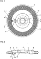
- a sealing housing 2 composed of a case 2-1 and a cover 2-2 is supported via bearings 13 and 14 on a rotary shaft (drive shaft) 1 rotated according to driving of a drive unit (engine), and a drive disk 3 fixed to the rotary shaft 1 is incorporated in a torque transmission chamber 6 within the sealed housing 2.
- a drive shaft drive shaft 1 rotated according to driving of a drive unit (engine)
- a drive disk 3 fixed to the rotary shaft 1 is incorporated in a torque transmission chamber 6 within the sealed housing 2.
- the drive disk 3 is configured such that an substantially triangular window hole 7 communicating with the torque transmission chamber 6 is provided at one end of an annular oil reserving chamber (oil storage chamber) 5 provided by making inside of the drive disk 3 hollow, and in addition, a mounting portion 11 for a valve member 10 described later is provided on the reverse side of the disk on the opposite side to the approximately triangular window hole 7, and arc-like disk supporting legs 12 are provided in a projecting fashion at positions opposed to each other outside of a shaft hole 9 of a disk center concentrically with the shaft hole 9, and the drive disk 3 is fixed to a section of the rotary shaft 1 positioned between the bearings 13 and 14 that support the sealed housing 2.
- the drive disk 3 includes an oil supply chamber 5-1 formed of a partition wall 5-2 and a plate-like partition wall 5-3 in the annular oil reserving chamber 5, the partition wall 5-2 being composed of an arc-like partition wall concentric to the oil reserving chamber 5, the plate-like partition wall 5-3 serving to shield one end of the arc-like wall 5-2 , and at least one oil circulating flow passage hole (oil supply port) 8 and an oil recovery port 8-1 communicating with a torque transmission gap are provided on a side wall face on an end side of the window hole 7 in the oil supply chamber.
- an angle ⁇ Fig.
- the angle preferably falls into a range from 150° to 200°.
- the reason is that in the case of an angle of less than 150°, when the oil circulating flow passage hole (oil supply port) 8 and the oil recovery port 8-1 are positioned just below, a leaking amount of oil which cannot be stored in the oil reserving chamber into the torque transmission chamber cannot be reduced effectively, while in the case of an angle of more than 200°, when the oil supply port 8 and the oil recovery port 8-1 are positioned just below, even if a leaking amount of oil which cannot be stored in the oil reserving chamber into the torque transmission chamber can be reduced depending to an angle regarding the leaking amount of oil from the oil reserving chamber into the torque transmission chamber side, a problem that flow of oil deteriorates and oil does not enter the oil supply port smoothly occurs when the angle become excessively large.
- the volume of the oil supply chamber 5-1 occupying the oil reserving chamber 5 preferably falls into a range from 30 to 40% of the oil reserving chamber 5.
- the reason is that in the case of a volume of less than 30%, when the oil supply port 8 and the oil recovery port 8-1 are positioned just below, a leaking amount of oil which cannot be stored in the oil reserving chamber into the torque transmission chamber cannot be reduced effectively, while in the case of a volume of more than 40%, a problem that flow of oil deteriorates and oil does not enter the oil supply port smoothly occurs, like the case where the oil reserving chamber 5-1 is defined by the angle.
- reference numeral 4 denotes a separate plate and 8-2 denotes an oil recovery path.
- the valve member 10 for feeding oil which opens or closes the oil circulating flow passage hole 8 provided in the drive disk 3, is composed of a leaf spring 10-1 and an armature 10-2, and a proximal end of the leaf spring 10-1 is fixed, by a screw or the like, to the mounting portion 11 provided on the reverse side of the disk such that the armature 10-2 of the valve member is positioned in the vicinity of the rotary shaft 1. It goes without saying that a portion of the leaf spring 10-1 of the valve member 10 opposite to the proximal end is exposed from the approximately triangular window hole 7 provided in the drive disk 3 to the side of the cover 2-2 so that a distal end portion thereof is positioned to face the oil circulating flow passage hole 8.
- a ring-like electromagnet 16 is supported on a ring-like electromagnet support 17 supported via a bearing 15 on the rotary shaft 1
- a first magnetic ring 18 is arranged on an outer periphery of a cylindrical non-magnetic ring 19 fixed on an outer periphery of the rotary shaft 1 between the electromagnet 16 and the valve member 10
- a second magnetic ring 20 is further fitted on and fixed to the rotary shaft 1 between the electromagnet support 17 of the electromagnet 16 and the rotary shaft 1 so as to substantially come in contact with the electromagnet support 17.
- the second magnetic ring 20 is provided for transmitting magnetic flux of the electromagnet 16 to the armature 10-2 of the valve member efficiently.
- the armature 10-2 is spaced from the oil circulating flow passage hole 8 of the drive disk 3 according to the function of the leaf spring 10-1 so that the oil circulating flow passage hole 8 provided in the oil supply chamber 5-1 is opened, the oil reserving chamber 5 and the torque transmission chamber 6 communicate with each other, oil in the oil reserving chamber 5 is supplied from the oil supply chamber 5-1 provided in the oil reserving chamber 5 to the torque transmission chamber 6, which results in suppression of unnecessary rotation of the cooling fan (not shown) occurring when the cooling fan transitions from the stop state to the rotating state.
- Fig. 5A shows a case where the oil circulating flow passage hole (oil supply port) 8 and the oil recovery port 8-1 are positioned just below, where since oil does not accumulate in the oil supply chamber 5-1, a leaking oil amount of oil which cannot be stored in the annular oil reserving chamber 5 into the torque transmission chamber 6 can be reduced at a stop time of the cooling fan.
- Fig. 5B shows a case where the oil circulating flow passage hole (oil supply port) 8 and the oil recovery port 8-1 are positioned just above, where a leaking oil amount of oil which cannot be stored in the annular oil reserving chamber 5 into the torque transmission chamber 6 can also be reduced at a stop time of the cooling fan, like the case shown in Fig. 5A.
- Fig. 5B shows a case where the oil circulating flow passage hole (oil supply port) 8 and the oil recovery port 8-1 are positioned just above, where a leaking oil amount of oil which cannot be stored in the annular oil reserving chamber 5 into the torque transmission
- FIG. 5C shows a case where the oil circulating flow passage hole (oil supply port) 8 and the oil recovery port 8-1 are positioned just beside (on a left side), where a leaking oil amount of oil which cannot be stored in the annular oil reserving chamber 5 to the torque transmission chamber 6 can also be reduced at a stop time of the cooling fan, like the cases shown in Figs. 5A and 5B . Further, Fig.
- FIG. 5D shows a case where the oil circulating flow passage hole (oil supply port) 8 and the oil recovery port 8-1 are positioned just beside (on a right side), where a leaking oil amount of oil which cannot be stored in the annular oil reserving chamber 5 into the torque transmission chamber 6 can also be reduced at a stop time of the cooling fan, like the cases shown in Figs. 5A, 5B and 5C .
- a magnetic circuit is composed of the electromagnet 16, the first magnetic ring 18, the armature 10-2, the rotary shaft 1, and the second magnetic ring 20, and magnetic flux flows in the order of the electromagnet 16 ⁇ the first magnetic ring 18 ⁇ the armature 10-2 ⁇ the rotary shaft 1 ⁇ the second magnetic ring 20, so that magnetic flux of the electromagnet 16 is transmitted to the armature 10-2 of the valve member efficiently, which can result in reduction of power consumption.
Landscapes
- Engineering & Computer Science (AREA)
- General Engineering & Computer Science (AREA)
- Physics & Mathematics (AREA)
- Mechanical Engineering (AREA)
- Electromagnetism (AREA)
- Fluid Mechanics (AREA)
- Chemical & Material Sciences (AREA)
- Combustion & Propulsion (AREA)
- Hydraulic Clutches, Magnetic Clutches, Fluid Clutches, And Fluid Joints (AREA)
- General Details Of Gearings (AREA)
- Dynamo-Electric Clutches, Dynamo-Electric Brakes (AREA)
Applications Claiming Priority (1)
| Application Number | Priority Date | Filing Date | Title |
|---|---|---|---|
| JP2014017033A JP6391141B2 (ja) | 2014-01-31 | 2014-01-31 | 外部制御式ファン・クラッチ装置 |
Publications (4)
| Publication Number | Publication Date |
|---|---|
| EP2902651A2 EP2902651A2 (en) | 2015-08-05 |
| EP2902651A3 EP2902651A3 (en) | 2016-05-25 |
| EP2902651B1 EP2902651B1 (en) | 2017-03-15 |
| EP2902651B9 true EP2902651B9 (en) | 2017-09-20 |
Family
ID=52596289
Family Applications (1)
| Application Number | Title | Priority Date | Filing Date |
|---|---|---|---|
| EP15151991.5A Active EP2902651B9 (en) | 2014-01-31 | 2015-01-21 | External-control type fan clutch device |
Country Status (5)
| Country | Link |
|---|---|
| US (1) | US9328781B2 (https=) |
| EP (1) | EP2902651B9 (https=) |
| JP (1) | JP6391141B2 (https=) |
| KR (1) | KR101653483B1 (https=) |
| CN (1) | CN104819258B (https=) |
Families Citing this family (11)
| Publication number | Priority date | Publication date | Assignee | Title |
|---|---|---|---|---|
| JP6562749B2 (ja) * | 2015-07-27 | 2019-08-21 | 臼井国際産業株式会社 | 外部制御式ファン・クラッチ装置 |
| EP3359835B1 (en) | 2015-10-05 | 2020-07-22 | Horton, Inc. | Live center viscous clutch |
| KR102607230B1 (ko) * | 2015-12-03 | 2023-11-27 | 호르톤 인코포레이티드 | 점성 클러치 유체 포착 시스템 |
| AU2017288125C1 (en) * | 2016-06-29 | 2022-07-14 | Horton, Inc. | Viscous clutch and associated electromagnetic coil |
| US10655688B2 (en) | 2018-02-16 | 2020-05-19 | Standard Motor Products, Inc. | Fan-coupling device with unitary magnetic pole construction |
| DE102018216478A1 (de) * | 2018-09-26 | 2020-03-26 | Mahle International Gmbh | Flüssigkeitsreibkupplung |
| US11441621B2 (en) | 2019-01-31 | 2022-09-13 | Horton, Inc. | Pump and wiper assembly, associated viscous clutch and associated method |
| EP4121666A4 (en) | 2020-05-14 | 2024-04-17 | Horton, Inc. | Valve control system for viscous friction clutch |
| CN111981061B (zh) * | 2020-08-24 | 2021-12-21 | 浙江英洛华赫兹电气有限公司 | 高制动力矩的电磁失电制动器 |
| KR20240167439A (ko) | 2022-03-24 | 2024-11-26 | 호르톤 인코포레이티드 | 점성 클러치용 전방-장착 전자기 코일, 모듈형 밸브 및 전방 허브 서브어셈블리가 구비된 점성 클러치, 및 이의 제조 방법 |
| CN116255706B (zh) * | 2023-03-13 | 2025-06-17 | 珠海格力电器股份有限公司 | 控制方法、装置、电子设备及存储介质 |
Family Cites Families (13)
| Publication number | Priority date | Publication date | Assignee | Title |
|---|---|---|---|---|
| DE19533641B4 (de) * | 1995-09-12 | 2005-11-10 | Behr Gmbh & Co. Kg | Flüssigkeitsreibungskupplung |
| DE19753725C2 (de) * | 1997-12-04 | 2001-03-08 | Behr Gmbh & Co | Flüssigkeitsreibungskupplung |
| DE10157822A1 (de) * | 2001-11-24 | 2003-06-05 | Behr Gmbh & Co | Elektromagnetisch angesteuerte Flüssigkeitsreibungskupplung |
| JP4353396B2 (ja) * | 2002-10-22 | 2009-10-28 | 臼井国際産業株式会社 | 外部制御式ファン・カップリング装置 |
| JP2004340373A (ja) * | 2003-04-21 | 2004-12-02 | Usui Kokusai Sangyo Kaisha Ltd | 外部制御式ファンクラッチの制御方法 |
| JP4813868B2 (ja) * | 2004-11-09 | 2011-11-09 | 臼井国際産業株式会社 | 外部制御式ファン・カップリング装置 |
| JP4813869B2 (ja) * | 2004-11-09 | 2011-11-09 | 臼井国際産業株式会社 | 外部制御式ファン・カップリング装置 |
| JP5188968B2 (ja) * | 2005-07-29 | 2013-04-24 | ホートン, インコーポレイテッド | 粘性クラッチアセンブリ及び粘性クラッチの運転方法 |
| US7407046B2 (en) * | 2005-09-26 | 2008-08-05 | Usui International Corp. | Adaptive control of externally controlled fan drive |
| JP2007120645A (ja) * | 2005-10-28 | 2007-05-17 | Aisin Seiki Co Ltd | 外部制御式流体継手 |
| DE102007019088B4 (de) * | 2007-04-23 | 2018-07-26 | Mahle International Gmbh | Flüssigkeitsreibungskupplung für den Antrieb eines Lüfters in einem Kraftfahrzeug |
| JP5522677B2 (ja) * | 2010-04-28 | 2014-06-18 | 臼井国際産業株式会社 | 高反応型流体式ファン・カップリング装置 |
| JP6358643B2 (ja) * | 2013-06-06 | 2018-07-18 | 臼井国際産業株式会社 | 外部制御式ファン・クラッチ装置 |
-
2014
- 2014-01-31 JP JP2014017033A patent/JP6391141B2/ja active Active
- 2014-12-24 CN CN201410814548.XA patent/CN104819258B/zh active Active
-
2015
- 2015-01-21 EP EP15151991.5A patent/EP2902651B9/en active Active
- 2015-01-21 US US14/601,575 patent/US9328781B2/en active Active
- 2015-01-29 KR KR1020150014213A patent/KR101653483B1/ko active Active
Also Published As
| Publication number | Publication date |
|---|---|
| JP2015143547A (ja) | 2015-08-06 |
| JP6391141B2 (ja) | 2018-09-19 |
| EP2902651A3 (en) | 2016-05-25 |
| EP2902651B1 (en) | 2017-03-15 |
| EP2902651A2 (en) | 2015-08-05 |
| CN104819258A (zh) | 2015-08-05 |
| KR20150091250A (ko) | 2015-08-10 |
| US20150219168A1 (en) | 2015-08-06 |
| US9328781B2 (en) | 2016-05-03 |
| KR101653483B1 (ko) | 2016-09-01 |
| CN104819258B (zh) | 2017-04-05 |
Similar Documents
| Publication | Publication Date | Title |
|---|---|---|
| EP2902651B9 (en) | External-control type fan clutch device | |
| US6752251B2 (en) | Electronically controlled viscous fan drive | |
| EP2811133B1 (en) | External control type fan clutch device | |
| EP3359836B1 (en) | Morning sickness valve system for viscous clutch | |
| EP2947345A1 (en) | Fluid fan clutch device | |
| EP3176456A1 (en) | Temperature-sensitive fluid fan clutch device | |
| US7621386B2 (en) | Viscous fan drive having modified land design and armature venting | |
| CN115013137A (zh) | 一种电控硅油调速水泵 | |
| US9903423B2 (en) | Fluid friction clutch | |
| US7293636B2 (en) | Electronically controlled viscous fan drive having cast channels | |
| US10670089B2 (en) | External control type fan clutch device | |
| US10344775B2 (en) | Water pump | |
| US20160131204A1 (en) | Fluid fan clutch | |
| US20160273542A1 (en) | Rotary pump with axially displaceable, closeable rotor | |
| CN104234767A (zh) | 气门定时控制装置 | |
| US7112156B2 (en) | Transmission with miniature motor for control to oil flow | |
| WO2016134201A1 (en) | Fluid friction clutch | |
| JP2018004040A (ja) | 流体式ファンクラッチ | |
| JP2002013556A (ja) | 外部制御式ファン・カップリング装置 | |
| JP2017137907A (ja) | 動力伝達装置 |
Legal Events
| Date | Code | Title | Description |
|---|---|---|---|
| PUAI | Public reference made under article 153(3) epc to a published international application that has entered the european phase |
Free format text: ORIGINAL CODE: 0009012 |
|
| 17P | Request for examination filed |
Effective date: 20150121 |
|
| AK | Designated contracting states |
Kind code of ref document: A2 Designated state(s): AL AT BE BG CH CY CZ DE DK EE ES FI FR GB GR HR HU IE IS IT LI LT LU LV MC MK MT NL NO PL PT RO RS SE SI SK SM TR |
|
| AX | Request for extension of the european patent |
Extension state: BA ME |
|
| PUAL | Search report despatched |
Free format text: ORIGINAL CODE: 0009013 |
|
| AK | Designated contracting states |
Kind code of ref document: A3 Designated state(s): AL AT BE BG CH CY CZ DE DK EE ES FI FR GB GR HR HU IE IS IT LI LT LU LV MC MK MT NL NO PL PT RO RS SE SI SK SM TR |
|
| AX | Request for extension of the european patent |
Extension state: BA ME |
|
| RIC1 | Information provided on ipc code assigned before grant |
Ipc: F16D 35/02 20060101AFI20160419BHEP |
|
| 17Q | First examination report despatched |
Effective date: 20160517 |
|
| GRAP | Despatch of communication of intention to grant a patent |
Free format text: ORIGINAL CODE: EPIDOSNIGR1 |
|
| INTG | Intention to grant announced |
Effective date: 20161122 |
|
| RBV | Designated contracting states (corrected) |
Designated state(s): AL AT BE BG CH CY CZ DE DK EE ES FI FR GB GR HR HU IE IS IT LI LT LU LV MC MK MT NL NO PL PT RO RS SE SI SK SM TR |
|
| GRAS | Grant fee paid |
Free format text: ORIGINAL CODE: EPIDOSNIGR3 |
|
| GRAA | (expected) grant |
Free format text: ORIGINAL CODE: 0009210 |
|
| AK | Designated contracting states |
Kind code of ref document: B1 Designated state(s): AL AT BE BG CH CY CZ DE DK EE ES FI FR GB GR HR HU IE IS IT LI LT LU LV MC MK MT NL NO PL PT RO RS SE SI SK SM TR |
|
| REG | Reference to a national code |
Ref country code: CH Ref legal event code: EP Ref country code: GB Ref legal event code: FG4D |
|
| REG | Reference to a national code |
Ref country code: IE Ref legal event code: FG4D |
|
| REG | Reference to a national code |
Ref country code: AT Ref legal event code: REF Ref document number: 875909 Country of ref document: AT Kind code of ref document: T Effective date: 20170415 |
|
| REG | Reference to a national code |
Ref country code: DE Ref legal event code: R096 Ref document number: 602015001786 Country of ref document: DE |
|
| REG | Reference to a national code |
Ref country code: SE Ref legal event code: TRGR |
|
| REG | Reference to a national code |
Ref country code: NL Ref legal event code: MP Effective date: 20170315 |
|
| REG | Reference to a national code |
Ref country code: LT Ref legal event code: MG4D |
|
| PG25 | Lapsed in a contracting state [announced via postgrant information from national office to epo] |
Ref country code: NO Free format text: LAPSE BECAUSE OF FAILURE TO SUBMIT A TRANSLATION OF THE DESCRIPTION OR TO PAY THE FEE WITHIN THE PRESCRIBED TIME-LIMIT Effective date: 20170615 Ref country code: GR Free format text: LAPSE BECAUSE OF FAILURE TO SUBMIT A TRANSLATION OF THE DESCRIPTION OR TO PAY THE FEE WITHIN THE PRESCRIBED TIME-LIMIT Effective date: 20170616 Ref country code: LT Free format text: LAPSE BECAUSE OF FAILURE TO SUBMIT A TRANSLATION OF THE DESCRIPTION OR TO PAY THE FEE WITHIN THE PRESCRIBED TIME-LIMIT Effective date: 20170315 Ref country code: HR Free format text: LAPSE BECAUSE OF FAILURE TO SUBMIT A TRANSLATION OF THE DESCRIPTION OR TO PAY THE FEE WITHIN THE PRESCRIBED TIME-LIMIT Effective date: 20170315 Ref country code: FI Free format text: LAPSE BECAUSE OF FAILURE TO SUBMIT A TRANSLATION OF THE DESCRIPTION OR TO PAY THE FEE WITHIN THE PRESCRIBED TIME-LIMIT Effective date: 20170315 |
|
| REG | Reference to a national code |
Ref country code: AT Ref legal event code: MK05 Ref document number: 875909 Country of ref document: AT Kind code of ref document: T Effective date: 20170315 |
|
| PG25 | Lapsed in a contracting state [announced via postgrant information from national office to epo] |
Ref country code: LV Free format text: LAPSE BECAUSE OF FAILURE TO SUBMIT A TRANSLATION OF THE DESCRIPTION OR TO PAY THE FEE WITHIN THE PRESCRIBED TIME-LIMIT Effective date: 20170315 Ref country code: BG Free format text: LAPSE BECAUSE OF FAILURE TO SUBMIT A TRANSLATION OF THE DESCRIPTION OR TO PAY THE FEE WITHIN THE PRESCRIBED TIME-LIMIT Effective date: 20170615 Ref country code: RS Free format text: LAPSE BECAUSE OF FAILURE TO SUBMIT A TRANSLATION OF THE DESCRIPTION OR TO PAY THE FEE WITHIN THE PRESCRIBED TIME-LIMIT Effective date: 20170315 |
|
| PG25 | Lapsed in a contracting state [announced via postgrant information from national office to epo] |
Ref country code: NL Free format text: LAPSE BECAUSE OF FAILURE TO SUBMIT A TRANSLATION OF THE DESCRIPTION OR TO PAY THE FEE WITHIN THE PRESCRIBED TIME-LIMIT Effective date: 20170315 |
|
| PG25 | Lapsed in a contracting state [announced via postgrant information from national office to epo] |
Ref country code: RO Free format text: LAPSE BECAUSE OF FAILURE TO SUBMIT A TRANSLATION OF THE DESCRIPTION OR TO PAY THE FEE WITHIN THE PRESCRIBED TIME-LIMIT Effective date: 20170315 Ref country code: SK Free format text: LAPSE BECAUSE OF FAILURE TO SUBMIT A TRANSLATION OF THE DESCRIPTION OR TO PAY THE FEE WITHIN THE PRESCRIBED TIME-LIMIT Effective date: 20170315 Ref country code: ES Free format text: LAPSE BECAUSE OF FAILURE TO SUBMIT A TRANSLATION OF THE DESCRIPTION OR TO PAY THE FEE WITHIN THE PRESCRIBED TIME-LIMIT Effective date: 20170315 Ref country code: CZ Free format text: LAPSE BECAUSE OF FAILURE TO SUBMIT A TRANSLATION OF THE DESCRIPTION OR TO PAY THE FEE WITHIN THE PRESCRIBED TIME-LIMIT Effective date: 20170315 Ref country code: AT Free format text: LAPSE BECAUSE OF FAILURE TO SUBMIT A TRANSLATION OF THE DESCRIPTION OR TO PAY THE FEE WITHIN THE PRESCRIBED TIME-LIMIT Effective date: 20170315 Ref country code: EE Free format text: LAPSE BECAUSE OF FAILURE TO SUBMIT A TRANSLATION OF THE DESCRIPTION OR TO PAY THE FEE WITHIN THE PRESCRIBED TIME-LIMIT Effective date: 20170315 |
|
| PG25 | Lapsed in a contracting state [announced via postgrant information from national office to epo] |
Ref country code: PL Free format text: LAPSE BECAUSE OF FAILURE TO SUBMIT A TRANSLATION OF THE DESCRIPTION OR TO PAY THE FEE WITHIN THE PRESCRIBED TIME-LIMIT Effective date: 20170315 Ref country code: PT Free format text: LAPSE BECAUSE OF FAILURE TO SUBMIT A TRANSLATION OF THE DESCRIPTION OR TO PAY THE FEE WITHIN THE PRESCRIBED TIME-LIMIT Effective date: 20170717 Ref country code: IS Free format text: LAPSE BECAUSE OF FAILURE TO SUBMIT A TRANSLATION OF THE DESCRIPTION OR TO PAY THE FEE WITHIN THE PRESCRIBED TIME-LIMIT Effective date: 20170715 Ref country code: SM Free format text: LAPSE BECAUSE OF FAILURE TO SUBMIT A TRANSLATION OF THE DESCRIPTION OR TO PAY THE FEE WITHIN THE PRESCRIBED TIME-LIMIT Effective date: 20170315 |
|
| REG | Reference to a national code |
Ref country code: DE Ref legal event code: R097 Ref document number: 602015001786 Country of ref document: DE |
|
| PLBE | No opposition filed within time limit |
Free format text: ORIGINAL CODE: 0009261 |
|
| STAA | Information on the status of an ep patent application or granted ep patent |
Free format text: STATUS: NO OPPOSITION FILED WITHIN TIME LIMIT |
|
| REG | Reference to a national code |
Ref country code: FR Ref legal event code: PLFP Year of fee payment: 4 |
|
| PG25 | Lapsed in a contracting state [announced via postgrant information from national office to epo] |
Ref country code: DK Free format text: LAPSE BECAUSE OF FAILURE TO SUBMIT A TRANSLATION OF THE DESCRIPTION OR TO PAY THE FEE WITHIN THE PRESCRIBED TIME-LIMIT Effective date: 20170315 |
|
| 26N | No opposition filed |
Effective date: 20171218 |
|
| PG25 | Lapsed in a contracting state [announced via postgrant information from national office to epo] |
Ref country code: SI Free format text: LAPSE BECAUSE OF FAILURE TO SUBMIT A TRANSLATION OF THE DESCRIPTION OR TO PAY THE FEE WITHIN THE PRESCRIBED TIME-LIMIT Effective date: 20170315 Ref country code: IT Free format text: LAPSE BECAUSE OF FAILURE TO SUBMIT A TRANSLATION OF THE DESCRIPTION OR TO PAY THE FEE WITHIN THE PRESCRIBED TIME-LIMIT Effective date: 20170315 |
|
| REG | Reference to a national code |
Ref country code: CH Ref legal event code: PL |
|
| PG25 | Lapsed in a contracting state [announced via postgrant information from national office to epo] |
Ref country code: LU Free format text: LAPSE BECAUSE OF NON-PAYMENT OF DUE FEES Effective date: 20180121 |
|
| REG | Reference to a national code |
Ref country code: IE Ref legal event code: MM4A |
|
| REG | Reference to a national code |
Ref country code: BE Ref legal event code: MM Effective date: 20180131 |
|
| PG25 | Lapsed in a contracting state [announced via postgrant information from national office to epo] |
Ref country code: LI Free format text: LAPSE BECAUSE OF NON-PAYMENT OF DUE FEES Effective date: 20180131 Ref country code: BE Free format text: LAPSE BECAUSE OF NON-PAYMENT OF DUE FEES Effective date: 20180131 Ref country code: CH Free format text: LAPSE BECAUSE OF NON-PAYMENT OF DUE FEES Effective date: 20180131 |
|
| PG25 | Lapsed in a contracting state [announced via postgrant information from national office to epo] |
Ref country code: IE Free format text: LAPSE BECAUSE OF NON-PAYMENT OF DUE FEES Effective date: 20180121 |
|
| PG25 | Lapsed in a contracting state [announced via postgrant information from national office to epo] |
Ref country code: MC Free format text: LAPSE BECAUSE OF FAILURE TO SUBMIT A TRANSLATION OF THE DESCRIPTION OR TO PAY THE FEE WITHIN THE PRESCRIBED TIME-LIMIT Effective date: 20170315 |
|
| GBPC | Gb: european patent ceased through non-payment of renewal fee |
Effective date: 20190121 |
|
| PG25 | Lapsed in a contracting state [announced via postgrant information from national office to epo] |
Ref country code: GB Free format text: LAPSE BECAUSE OF NON-PAYMENT OF DUE FEES Effective date: 20190121 |
|
| PG25 | Lapsed in a contracting state [announced via postgrant information from national office to epo] |
Ref country code: MT Free format text: LAPSE BECAUSE OF NON-PAYMENT OF DUE FEES Effective date: 20180121 |
|
| PG25 | Lapsed in a contracting state [announced via postgrant information from national office to epo] |
Ref country code: TR Free format text: LAPSE BECAUSE OF FAILURE TO SUBMIT A TRANSLATION OF THE DESCRIPTION OR TO PAY THE FEE WITHIN THE PRESCRIBED TIME-LIMIT Effective date: 20170315 |
|
| PG25 | Lapsed in a contracting state [announced via postgrant information from national office to epo] |
Ref country code: CY Free format text: LAPSE BECAUSE OF FAILURE TO SUBMIT A TRANSLATION OF THE DESCRIPTION OR TO PAY THE FEE WITHIN THE PRESCRIBED TIME-LIMIT Effective date: 20170315 Ref country code: HU Free format text: LAPSE BECAUSE OF FAILURE TO SUBMIT A TRANSLATION OF THE DESCRIPTION OR TO PAY THE FEE WITHIN THE PRESCRIBED TIME-LIMIT; INVALID AB INITIO Effective date: 20150121 Ref country code: MK Free format text: LAPSE BECAUSE OF NON-PAYMENT OF DUE FEES Effective date: 20170315 |
|
| PG25 | Lapsed in a contracting state [announced via postgrant information from national office to epo] |
Ref country code: AL Free format text: LAPSE BECAUSE OF FAILURE TO SUBMIT A TRANSLATION OF THE DESCRIPTION OR TO PAY THE FEE WITHIN THE PRESCRIBED TIME-LIMIT Effective date: 20170315 |
|
| PGFP | Annual fee paid to national office [announced via postgrant information from national office to epo] |
Ref country code: SE Payment date: 20260121 Year of fee payment: 12 |
|
| PGFP | Annual fee paid to national office [announced via postgrant information from national office to epo] |
Ref country code: DE Payment date: 20260120 Year of fee payment: 12 |
|
| PGFP | Annual fee paid to national office [announced via postgrant information from national office to epo] |
Ref country code: FR Payment date: 20260127 Year of fee payment: 12 |