EP2902622B1 - Wind power generator - Google Patents
Wind power generator Download PDFInfo
- Publication number
- EP2902622B1 EP2902622B1 EP14197149.9A EP14197149A EP2902622B1 EP 2902622 B1 EP2902622 B1 EP 2902622B1 EP 14197149 A EP14197149 A EP 14197149A EP 2902622 B1 EP2902622 B1 EP 2902622B1
- Authority
- EP
- European Patent Office
- Prior art keywords
- yaw
- power generator
- gearbox
- wind power
- gear
- Prior art date
- Legal status (The legal status is an assumption and is not a legal conclusion. Google has not performed a legal analysis and makes no representation as to the accuracy of the status listed.)
- Active
Links
- 238000010586 diagram Methods 0.000 description 27
- 238000012544 monitoring process Methods 0.000 description 7
- 238000010248 power generation Methods 0.000 description 7
- 230000000694 effects Effects 0.000 description 3
- 238000007789 sealing Methods 0.000 description 3
- 230000008859 change Effects 0.000 description 2
- 238000013459 approach Methods 0.000 description 1
- 238000012217 deletion Methods 0.000 description 1
- 230000037430 deletion Effects 0.000 description 1
- 238000013461 design Methods 0.000 description 1
- 238000001514 detection method Methods 0.000 description 1
- 238000009434 installation Methods 0.000 description 1
- 238000012423 maintenance Methods 0.000 description 1
- 238000007726 management method Methods 0.000 description 1
- 238000012986 modification Methods 0.000 description 1
- 230000004048 modification Effects 0.000 description 1
- 230000008439 repair process Effects 0.000 description 1
- 238000013024 troubleshooting Methods 0.000 description 1
- 238000010792 warming Methods 0.000 description 1
Images


Classifications
-
- F—MECHANICAL ENGINEERING; LIGHTING; HEATING; WEAPONS; BLASTING
- F03—MACHINES OR ENGINES FOR LIQUIDS; WIND, SPRING, OR WEIGHT MOTORS; PRODUCING MECHANICAL POWER OR A REACTIVE PROPULSIVE THRUST, NOT OTHERWISE PROVIDED FOR
- F03D—WIND MOTORS
- F03D7/00—Controlling wind motors
- F03D7/02—Controlling wind motors the wind motors having rotation axis substantially parallel to the air flow entering the rotor
-
- F—MECHANICAL ENGINEERING; LIGHTING; HEATING; WEAPONS; BLASTING
- F03—MACHINES OR ENGINES FOR LIQUIDS; WIND, SPRING, OR WEIGHT MOTORS; PRODUCING MECHANICAL POWER OR A REACTIVE PROPULSIVE THRUST, NOT OTHERWISE PROVIDED FOR
- F03D—WIND MOTORS
- F03D80/00—Details, components or accessories not provided for in groups F03D1/00 - F03D17/00
- F03D80/80—Arrangement of components within nacelles or towers
- F03D80/88—Arrangement of components within nacelles or towers of mechanical components
-
- F—MECHANICAL ENGINEERING; LIGHTING; HEATING; WEAPONS; BLASTING
- F03—MACHINES OR ENGINES FOR LIQUIDS; WIND, SPRING, OR WEIGHT MOTORS; PRODUCING MECHANICAL POWER OR A REACTIVE PROPULSIVE THRUST, NOT OTHERWISE PROVIDED FOR
- F03D—WIND MOTORS
- F03D1/00—Wind motors with rotation axis substantially parallel to the air flow entering the rotor
- F03D1/02—Wind motors with rotation axis substantially parallel to the air flow entering the rotor having a plurality of rotors
-
- F—MECHANICAL ENGINEERING; LIGHTING; HEATING; WEAPONS; BLASTING
- F03—MACHINES OR ENGINES FOR LIQUIDS; WIND, SPRING, OR WEIGHT MOTORS; PRODUCING MECHANICAL POWER OR A REACTIVE PROPULSIVE THRUST, NOT OTHERWISE PROVIDED FOR
- F03D—WIND MOTORS
- F03D13/00—Assembly, mounting or commissioning of wind motors; Arrangements specially adapted for transporting wind motor components
- F03D13/20—Arrangements for mounting or supporting wind motors; Masts or towers for wind motors
- F03D13/25—Arrangements for mounting or supporting wind motors; Masts or towers for wind motors specially adapted for offshore installation
-
- F—MECHANICAL ENGINEERING; LIGHTING; HEATING; WEAPONS; BLASTING
- F03—MACHINES OR ENGINES FOR LIQUIDS; WIND, SPRING, OR WEIGHT MOTORS; PRODUCING MECHANICAL POWER OR A REACTIVE PROPULSIVE THRUST, NOT OTHERWISE PROVIDED FOR
- F03D—WIND MOTORS
- F03D15/00—Transmission of mechanical power
-
- F—MECHANICAL ENGINEERING; LIGHTING; HEATING; WEAPONS; BLASTING
- F03—MACHINES OR ENGINES FOR LIQUIDS; WIND, SPRING, OR WEIGHT MOTORS; PRODUCING MECHANICAL POWER OR A REACTIVE PROPULSIVE THRUST, NOT OTHERWISE PROVIDED FOR
- F03D—WIND MOTORS
- F03D15/00—Transmission of mechanical power
- F03D15/10—Transmission of mechanical power using gearing not limited to rotary motion, e.g. with oscillating or reciprocating members
-
- F—MECHANICAL ENGINEERING; LIGHTING; HEATING; WEAPONS; BLASTING
- F03—MACHINES OR ENGINES FOR LIQUIDS; WIND, SPRING, OR WEIGHT MOTORS; PRODUCING MECHANICAL POWER OR A REACTIVE PROPULSIVE THRUST, NOT OTHERWISE PROVIDED FOR
- F03D—WIND MOTORS
- F03D7/00—Controlling wind motors
- F03D7/02—Controlling wind motors the wind motors having rotation axis substantially parallel to the air flow entering the rotor
- F03D7/0204—Controlling wind motors the wind motors having rotation axis substantially parallel to the air flow entering the rotor for orientation in relation to wind direction
-
- F—MECHANICAL ENGINEERING; LIGHTING; HEATING; WEAPONS; BLASTING
- F05—INDEXING SCHEMES RELATING TO ENGINES OR PUMPS IN VARIOUS SUBCLASSES OF CLASSES F01-F04
- F05B—INDEXING SCHEME RELATING TO WIND, SPRING, WEIGHT, INERTIA OR LIKE MOTORS, TO MACHINES OR ENGINES FOR LIQUIDS COVERED BY SUBCLASSES F03B, F03D AND F03G
- F05B2260/00—Function
- F05B2260/40—Transmission of power
- F05B2260/403—Transmission of power through the shape of the drive components
- F05B2260/4031—Transmission of power through the shape of the drive components as in toothed gearing
-
- Y—GENERAL TAGGING OF NEW TECHNOLOGICAL DEVELOPMENTS; GENERAL TAGGING OF CROSS-SECTIONAL TECHNOLOGIES SPANNING OVER SEVERAL SECTIONS OF THE IPC; TECHNICAL SUBJECTS COVERED BY FORMER USPC CROSS-REFERENCE ART COLLECTIONS [XRACs] AND DIGESTS
- Y02—TECHNOLOGIES OR APPLICATIONS FOR MITIGATION OR ADAPTATION AGAINST CLIMATE CHANGE
- Y02E—REDUCTION OF GREENHOUSE GAS [GHG] EMISSIONS, RELATED TO ENERGY GENERATION, TRANSMISSION OR DISTRIBUTION
- Y02E10/00—Energy generation through renewable energy sources
- Y02E10/70—Wind energy
- Y02E10/72—Wind turbines with rotation axis in wind direction
-
- Y—GENERAL TAGGING OF NEW TECHNOLOGICAL DEVELOPMENTS; GENERAL TAGGING OF CROSS-SECTIONAL TECHNOLOGIES SPANNING OVER SEVERAL SECTIONS OF THE IPC; TECHNICAL SUBJECTS COVERED BY FORMER USPC CROSS-REFERENCE ART COLLECTIONS [XRACs] AND DIGESTS
- Y02—TECHNOLOGIES OR APPLICATIONS FOR MITIGATION OR ADAPTATION AGAINST CLIMATE CHANGE
- Y02E—REDUCTION OF GREENHOUSE GAS [GHG] EMISSIONS, RELATED TO ENERGY GENERATION, TRANSMISSION OR DISTRIBUTION
- Y02E10/00—Energy generation through renewable energy sources
- Y02E10/70—Wind energy
- Y02E10/727—Offshore wind turbines
Definitions
- the present invention relates to a wind power generator.
- JP-2007-198167-A discloses a horizontal axial wind turbine in which a rotor including a hub and at least two blades, a nacelle pivotably supporting the rotor via a main shaft connected to the hub, a tower supporting the nacelle rotatable in a yawing direction, and a rotary damper that imposes, on yawing rotation of the nacelle, resistance torque which increases along with increase of rotary speed.
- both an output shaft of the rotary damper and a shaft fixed with a pinion gear are actuated in an interlocking manner, converting the rotary speed of the output shaft of the rotary damper to a low speed.
- the rotary damper has a characteristic in which the resistance torque is increased along with increase of the rotary speed, and the resistance torque having such a characteristic is imposed on yawing rotation of the nacelle. Due to this, larger yaw torque can be suppressed by the resistance torque of the rotary damper with the higher percentage, and motion energy of yawing rotation of the nacelle is dissipated by rotating the rotary damper. Consequently, there are effects in which a rapid speed change of yawing rotation at the nacelle is suppressed and the yawing rotary speed can be prevented from shifting to a high-speed area.
- the resistance torque to be imposed on the nacelle from the rotary damper is relatively little in a low speed area, and therefore, there is an effect in which drive control can be executed for yaw rotation of the nacelle without imposing heavy burden to a drive motor.
- a yaw driving unit is disposed at a connecting portion between a top portion of a tower and a nacelle in order that a rotor, namely, a plurality of blades and a hub can receive wind at a maximum, and orientation of the rotor, namely yaw control, is executed.
- yaw control is executed by the yaw driving unit such that a surface of the rotor directly faces the wind.
- the yaw control is generally executed so as to change positions of the nacelle and the rotor with respect to the tower by engaging a pinion gear of a yaw actuator provided at the nacelle with a yaw bearing gear provided at the top portion of the tower and driving the yaw actuator.
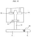
- the yaw actuator includes a drive motor, a gearbox, a pinion gear, and so on, however, the yaw control becomes impossible in the event of adhesion or sticking caused by seizure, foreign matter biting, etc. between a pinion gear 11 and a yaw bearing gear 9, namely, adhesion at the yaw driving unit as illustrated in Fig. 11 .
- the drive control for yawing rotation of the nacelle can be executed without imposing burden on the drive motor, but it is not possible to prevent the above-mentioned troubles of adhesion at the yaw driving unit caused by seizure, foreign matter biting between the pinion gear and the yaw bearing gear, gear deforming, and so on.
- An object of the present invention is to provide a wind power generator with high availability, wherein influence of yaw control trouble caused by failure of the yaw driving unit is minimized.
- the present invention is a wind power generator characterized in including: a tower disposed onshore or offshore and configured to be a supporting pillar of a power generator; a nacelle disposed on the tower and including the power generator inside thereof; and a rotor disposed at one end of the nacelle and including a blade and a hub configured to receive wind and convert the wind to rotational energy, wherein a yaw driving unit disposed at a connecting portion between the tower and the nacelle and configured to control positions of the nacelle and the rotor with respect to the tower is provided, and the yaw driving unit includes a releasing unit configured to release yaw drive force from being transmitted.
- the present invention is a wind power generator characterized in including: a tower disposed onshore or offshore and configured to be a supporting pillar of a power generator; a nacelle disposed on the tower and including the power generator inside thereof; and a rotor disposed at one end of the nacelle and including a blade and a hub configured to receive wind and convert the wind to rotational energy, wherein a yaw driving unit disposed at a connecting portion between the tower and the nacelle and configured to control positions of the nacelle and the rotor with respect to the tower is provided, the yaw driving unit includes a yaw bearing gear disposed at the tower, a pinion gear to be engaged with the yaw bearing gear, a gearbox connected to the pinion gear, and a drive motor connected to the pinion gear via the gearbox, and the gearbox includes a releasing unit configured to release yaw drive force from being transmitted.
- influence of yaw control trouble caused by failure of the yaw driving unit can be minimized in the wind power generator, and the wind power generator having high availability can be implemented.
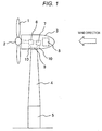
- Fig. 1 is a diagram illustrating an entire configuration of a wind power generator according to an embodiment of the present invention.
- the wind power generator according to a first embodiment includes, as illustrated in Fig. 1 , a foundation 5 disposed onshore or offshore and a nacelle 3 disposed on a tower 4 which is to be a supporting pillar of a power generator and including a step-up gear 6, the power generator 7, etc. inside thereof.
- a rotor formed of a hub 2 and a plurality of blades 1 is provided at an end of the nacelle 3. The rotor receives wind and converts the wind to rotational energy, and then transmits the rotational energy to the power generator 7 via the step-up gear 6 connected to the rotor, thereby generating power.
- a control panel 8 that includes control devices and instruments needed for controlling the wind power generator is also disposed.
- a yaw bearing gear 9 and a plurality of yaw actuators 10 are disposed at a connecting portion between the tower 4 and the nacelle 3, and function as a yaw driving unit (yaw turning unit) configured to control positions of the nacelle 3, the rotor, namely, the hub 2 and the plurality of blades 1 with respect to the tower 4.
- Fig. 1 is an example of a downwind wind power generator in which a rotor including the hub 2 and the plurality of blades 1 is disposed at an end portion of the nacelle 3 on a downwind side.
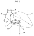
- Figs. 2 and 3 are diagrams illustrating a vicinity of a top portion of the tower 4 of the wind power generator according to the embodiment of the present invention.
- the nacelle 3 is illustrated in a transparent view such that a state in the vicinity of the top portion of the tower 4 can be easily grasped.
- the yaw bearing gear 9 constituting a part of the yaw driving unit is provided at the top portion of the tower 4.
- a plurality of the yaw actuators 10 constituting a part of the yaw driving unit is provided at the nacelle 3.
- the number of yaw actuators 10 to be installed is depending on a type and a size of the wind power generator.
- a power generation amount (output) is approximately 2 MW
- four yaw actuators are installed, and in the case where the power generation amount is approximately 5 MW, eight yaw actuators are installed so as to surround the top portion of the tower 4.
- the yaw actuator 10 is formed by joining a drive motor 13 which is to be a power source for yaw driving (yaw turning), a gearbox 12 that transmits drive force of the drive motor 13 to a pinion gear 11, and the pinion gear 11 disposed so as to be engaged with the yaw bearing gear 9.
- the wind power generator according to the first embodiment is configured as described above.
- the yaw actuator 10 is drive thereby controlling the positions of the nacelle 3 and the rotor with respect to the tower 4 such that the rotor, namely, the hub 2 and the plurality of blades 1 receive wind at a maximum. Further, the positions of the nacelle 3 and the rotor with respect to the tower 4 are controlled by a control device, such as a yaw inverter at the control panel 8, based on data from an anemoscope or the like set at the wind power generator.
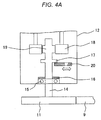
- Figs. 4A and 4B are diagrams illustrating a part of the gearbox 12 constituting the yaw actuator 10.
- the gearbox 12 includes combinations of gears of plural stages, namely, engagement portions of the gears, and Figs. 4A and 4B show a state of the engagement portions of the gears located close to a side of the engagement portion between the pinion gear 11 and the yaw bearing gear 9 out of the engagement portions of the gears of plural stages included inside the gearbox 12.
- the gearbox 12 includes an output shaft 14 connected to the pinion gear 11, and the pinion gear 11 is engaged with the yaw bearing gear 9 as illustrated in Fig. 4A .
- a bearing 15 receiving the output shaft 14 is disposed inside the gearbox 12, and a sealing member 16 is disposed so as to contact the bearing 15.
- oil is charged inside the gearbox 12, and the oil is prevented from leaking outside the gearbox 12 by the sealing member 16.
- the output shaft 14 includes a gear 19 on an opposite side of the portion connected to the pinion gear, and yaw drive force from the above-described drive motor 13 is transmitted from a gear 18, and transmitted to the pinion gear 11 via the output shaft 14.
- a projection which is to be a supporting portion 17 is formed on the output shaft 14 inside the gearbox 12, and is supported by a stopper 20.
- the gear 18 is engaged with the gear 19, and yaw drive force from the drive motor 13 is transmitted to the pinion gear 11 via the output shaft 14 by the stopper 20 thus supporting the supporting portion 17 disposed at the output shaft 14.
- the drive motor 13 is driven in accordance with wind directions, and the positions of the nacelle 3 and the rotor with respect to the tower 4 can be changed.
- the sealing member 16 functions as a cushion material of the supporting portion 17. Engagement between the yaw bearing gear 9 and the pinion gear 11 is disengaged by this, and the yaw drive force is released from being transmitted from the pinion gear 11 to the yaw bearing gear 9.
- Figs. 5A to 5C an opening (notch) is provided in the stopper 20.
- a stopper releasing unit such as a push stick 21 is inserted into the opening (notch) of the stopper 20, thereby moving the stopper 20 to separate from the supporting portion 17 and causing the pinion gear 11, output shaft 14, and gear 19 to fall below the gearbox 12.
- Fig. 5B is a plan view taken along a line a-a' in Fig. 5A . Also, Fig.
- FIG. 5C is a plan view taken along a line b-b' in Fig. 5B .
- the stopper 20 includes chamfered corners on a contacting surface with the supporting portion 17 so as to smoothly support the supporting portion 17.
- Adhesion between the yaw bearing gear 9 and the pinion gear 11 is detected by monitoring current values and the like of the yaw inverter at the control panel 8, for example.
- the above-described push stick 21 is manually pushed into the opening (notch) of the stopper 20 and the stopper 20 is released from supporting the supporting portion 17 in the case where the current value exceeds the current rating or exceeds the predetermined interlock value.
- an operating state becomes the free yaw mode (weathercock mode) by manually releasing the stopper 20 inside the gearbox 12 from supporting the supporting portion 17.
- the free yaw mode the positions of the nacelle 3 and rotor with respect to the tower 4 are changed in accordance with the wind direction. Consequently, the wind power generator can be continuously operated without excessive force applied to the rotor and the tower 4 by wind power. This minimizes influence of a yaw control trouble caused by failure of the yaw driving unit, and the wind power generator having high availability can be implemented.
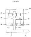
- Figs. 6A and 6B are diagrams illustrating a part of a yaw actuator 10 in a wind power generator according to a different embodiment of the present invention.
- the wind power generator according to a second embodiment will be described, omitting a detailed description for portions common with portions described in a first embodiment.
- a gearbox 12 constituting the yaw actuator 10 of the wind power generator according to the second embodiment has a configuration same as the first embodiment in a point that a projection to be a supporting portion 17 is provided at an output shaft 14. Further, another point same as the first embodiment is that a gear 18 and a gear 19 are engaged by the supporting portion 17 which is supported by a stopper 23, and yaw drive force from a drive motor 13 is transmitted to a pinion gear 11 via the output shaft 14.
- the stopper 23 according to the second embodiment is connected to a drive motor 22, and a releasing unit configured to release the yaw drive force from being transmitted, namely, the stopper 23 is moved by the drive motor 22 which is a releasing unit driving device such that the stopper 23 is released from supporting the supporting portion 17.
- the stopper 23 is moved by the drive motor 22 so as to separate from the supporting portion 17, thereby causing the pinion gear 11, output shaft 14, and gear 19 to fall below the gearbox 12 by their own weights. Engagement between the yaw bearing gear 9 and the pinion gear 11 is disengaged by this, and the yaw drive force is released from being transmitted from the pinion gear 11 to the yaw bearing gear 9.
- the stopper 23 is released by the drive motor 22 upon detecting adhesion between the yaw bearing gear 9 and pinion gear 11, same as the first embodiment. Same as the first embodiment, by monitoring current rating of a yaw inverter or setting a predetermined interlock value for a current value of the yaw inverter, the drive motor 22 is actuated to release the stopper 23 from supporting the supporting portion 17 in the case where a current value exceeds the current rating or exceeds the predetermined interlock value.
- the wind power generator of the second embodiment same as the first embodiment, even in the case where adhesion or sticking occurs between the yaw bearing gear 9 and the pinion gear 11, namely, adhesion occurs at the yaw driving unit, monitoring the current value of the yaw inverter or the like is executed in an interlocking manner and the stopper 23 inside the gearbox 12 is automatically released from supporting the supporting portion 17. Consequently, an operating state becomes the free yaw mode (weathercock mode) in which the positions of the nacelle 3 and rotor with respect to the tower 4 are changed in accordance with the wind directions, and the wind power generator can be continuously operated without excessive force applied to the rotor and the tower 4 by wind power. This minimizes influence of a yaw control trouble caused by failure of the yaw driving unit, and the wind power generator having high availability can be implemented.
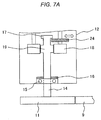
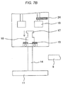
- Figs. 7A and 7B are diagrams illustrating a part of a yaw actuator 10 in a wind power generator according to a different embodiment of the present invention.
- the wind power generator according to a third embodiment will be described, omitting a detailed description for portions common with portions described in a first embodiment.
- a gearbox 12 constituting the yaw actuator 10 in the wind power generator according to the third embodiment has a configuration same as the first embodiment in a point that a projection which is to be a supporting portion 17 is provided at an output shaft 14. Further, another point same as the first embodiment is that a gear 18 and a gear 19 are engaged by the supporting portion 17 being supported by a stopper 24, and yaw drive force from a drive motor 13 is transmitted to a pinion gear 11 via the output shaft 14.
- a point different from the first embodiment is that the supporting portion 17 and the stopper 24 according to the third embodiment are disposed, inside the gearbox 12, on a side of a more center portion of the gearbox 12 than an engagement portion of gears located on a side of an engagement portion between the pinion gear 11 and the yaw bearing gear 9.
- the stopper 24 is moved manually like the first embodiment or automatically by the drive motor like the second embodiment so as to separate from the supporting portion 17, thereby causing the pinion gear 11, output shaft 14, and a gear 19 to fall below the gearbox 12 by their own weights. Engagement between the yaw bearing gear 9 and the pinion gear 11 is disengaged by this, and the yaw drive force is released from being transmitted from the pinion gear 11 to the yaw bearing gear 9.
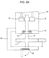
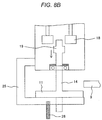
- Figs. 8A and 8B are diagrams illustrating a part of a yaw actuator 10 in a wind power generator according to a different embodiment of the present invention.
- the wind power generator according to a fourth embodiment will be described, omitting a detailed description for portions common with portions described in a first embodiment.
- the wind power generator according to the fourth embodiment is same as the first embodiment in a point that a gearbox 12 includes engagement potions of gears of plural stages inside thereof.
- the gearbox 12 according to the fourth embodiment a bracket 25 is provided outside thereof, and a stopper 26 is disposed at the bracket 25 so as to support the output shaft 14.
- the stopper 26 disposed outside the gearbox 12 is released, thereby causing the output shaft 14 to fall below the gearbox 12 passing through the bracket 25. Consequently, engagement between the pinion gear 11 and the yaw bearing gear 9 is disengaged and yaw drive force is released from being transmitted.
- the stopper 26 disposed outside the gearbox 12 is released upon detection of adhesion between the yaw bearing gear 9 and the pinion gear 11, same as the first embodiment.
- the stopper 26 is released from supporting the output shaft 14 in the case where a current value exceeds the current rating or exceeds the predetermined interlock value.
- the stopper 26 is released manually like the first embodiment or automatically by a drive motor like the second embodiment. By releasing the stopper 26 from supporting the output shaft 14, the pinion gear 11, the output shaft 14, and a gear 19 fall below the gearbox 12 by their own weights.
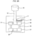
- Figs. 9A and 9B are diagrams illustrating a part of a yaw actuator 10 in a wind power generator according to a different embodiment of the present invention.
- the wind power generator according to a fifth embodiment will be described, omitting a detailed description for portions common with portions described in a first embodiment.
- a gearbox 12 constituting the yaw actuator 10 of the wind power generator according to the fifth embodiment is same as the first embodiment in a point of including engagement potions of gears of plural stages inside thereof.
- the gearbox 12 according to the fifth embodiment is different from other embodiments in a point that a projection which is to be a supporting portion 17 and a stopper 32 are disposed at an input shaft 33. Yaw drive force is released from being transmitted by disengaging engagement of gears disposed on a side of a drive motor 34 (drive motor 13 in Fig. 3 ) inside the gearbox 12.
- the stopper 32 is moved manually like the first embodiment or automatically by a drive motor like a second embodiment so as to separate from the supporting portion 17, thereby causing the input shaft 33 and a gear 31 to fall downward by their own weights.
- a gear 30 and the gear 31 is disengaged and the yaw drive force is released from being transmitted to the gear 31 and gear 30.
- the stopper 32 is released executed upon detecting adhesion between the yaw bearing gear 9 and the pinion gear 11, same as the first embodiment. Same as the first embodiment, by monitoring current rating of a yaw inverter or setting a predetermined interlock value for a current value of the yaw inverter, the stopper 32 is released from supporting the supporting portion 17, namely, the input shaft 33 in the case where a current value exceeds the amperage rating or exceeds the predetermined interlock value.
- the stopper 32 is released manually like the first embodiment or automatically by a drive motor like a second embodiment.
- the input shaft 33 and the gear 31 fall downward by their own weights by releasing the stopper 32 from supporting the supporting portion 17.
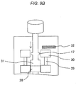
- Figs. 10A and 10B are diagrams illustrating a part of a yaw actuator 10 in a wind power generator according to a different embodiment of the present invention.
- the wind power generator according to a sixth embodiment will be described, omitting a detailed description for portions common with portions described in a first embodiment.
- a gearbox 12 constituting the yaw actuator 10 of the wind power generator according to the sixth embodiment is same as the first embodiment in a point of including engagement potions of gears of plural stages inside thereof. According to the gearbox 12 of the sixth embodiment, yaw drive force is released from being transmitted by disengaging engagement of gears disposed in a center portion inside the gearbox.
- a projection to be a supporting portion 17 is disposed at a shaft portion that connects a gear 37 to a gear 40 positioned at the center portion of the gearbox 12, and is supported by a stopper 38.
- the stopper 38 is moved manually like the first embodiment or automatically by a drive motor like a second embodiment so as to separate from the supporting portion 17, thereby causing the gears 37, gear 40, and shaft connecting these gears, which are positioned at the center portion of the gearbox 12, to fall downward by their own weights.
- engagement between a gear 36 and the gear 37 and between a gear 39 and the gear 40 is disengaged, and yaw drive force from the gear 39 to the gear 40 and the yaw drive force from the gear 37 to the gear 36 are released from being transmitted.
- the stopper 38 is released upon detecting adhesion between a yaw bearing gear 9 and a pinion gear 11, same as the first embodiment. Same as the first embodiment, by monitoring current rating of a yaw inverter or setting a predetermined interlock value for a current value of the yaw inverter, the stopper 38 is released from supporting the supporting portion 17 disposed at the shaft portion connecting the gear 37 to the gear 40 in the case where a current value exceeds the amperage rating or exceeds the predetermined interlock value.
- the present invention is not limited to the above-described embodiments and various modified examples are included.
- the above-described embodiments have been described in detail in order to explain the present invention in a comprehensible manner, and the present invention is not necessarily limited to include all of the described configurations.
- a part of the configuration according to one embodiment may be replaced by the configuration according to other embodiments, and further the configuration according to one embodiment can be added to the configuration according to other embodiments.
- addition, deletion, and replacement of other configurations may be made on a part of the configurations according to the respective embodiments.
Applications Claiming Priority (1)
| Application Number | Priority Date | Filing Date | Title |
|---|---|---|---|
| JP2014015465A JP6238770B2 (ja) | 2014-01-30 | 2014-01-30 | 風力発電装置 |
Publications (2)
| Publication Number | Publication Date |
|---|---|
| EP2902622A1 EP2902622A1 (en) | 2015-08-05 |
| EP2902622B1 true EP2902622B1 (en) | 2016-06-15 |
Family
ID=52102517
Family Applications (1)
| Application Number | Title | Priority Date | Filing Date |
|---|---|---|---|
| EP14197149.9A Active EP2902622B1 (en) | 2014-01-30 | 2014-12-10 | Wind power generator |
Country Status (4)
| Country | Link |
|---|---|
| EP (1) | EP2902622B1 (ja) |
| JP (1) | JP6238770B2 (ja) |
| KR (1) | KR101609478B1 (ja) |
| TW (1) | TWI547640B (ja) |
Families Citing this family (15)
| Publication number | Priority date | Publication date | Assignee | Title |
|---|---|---|---|---|
| JP6821345B2 (ja) | 2016-07-08 | 2021-01-27 | ナブテスコ株式会社 | 風車駆動システム及び風車 |
| DE102016114184A1 (de) * | 2016-08-01 | 2018-02-01 | Wobben Properties Gmbh | Maschinenhaus und Rotor für eine Windenergieanlage sowie Verfahren |
| JP6921514B2 (ja) * | 2016-12-07 | 2021-08-18 | ナブテスコ株式会社 | 風車駆動システム及び風車 |
| JP6921515B2 (ja) * | 2016-12-07 | 2021-08-18 | ナブテスコ株式会社 | 駆動装置、駆動装置ユニット及び風車 |
| JP6935297B2 (ja) * | 2017-10-19 | 2021-09-15 | 株式会社日立製作所 | 風力発電システム |
| JP2021102941A (ja) | 2019-12-25 | 2021-07-15 | ナブテスコ株式会社 | 風車用駆動制御装置、風車用電源装置、風力発電装置、制御方法、およびプログラム |
| JP7413007B2 (ja) * | 2019-12-25 | 2024-01-15 | ナブテスコ株式会社 | 風車用駆動制御装置、風車用駆動装置の制御方法、およびプログラム |
| JP2021127720A (ja) | 2020-02-13 | 2021-09-02 | ナブテスコ株式会社 | 検出回路付き固定具、検出回路、および風車用駆動装置 |
| JP2021152472A (ja) | 2020-03-24 | 2021-09-30 | ナブテスコ株式会社 | トルク推定装置、トルク推定方法及びトルク推定プログラム |
| JP2021174114A (ja) | 2020-04-21 | 2021-11-01 | ナブテスコ株式会社 | 状態監視装置及び状態監視方法 |
| JP2022043711A (ja) | 2020-09-04 | 2022-03-16 | ナブテスコ株式会社 | 出力装置、状態監視装置、風車、出力方法、状態監視方法及びプログラム |
| CN113202697B (zh) * | 2021-04-26 | 2023-02-24 | 上海泰胜风能装备股份有限公司 | 一种高阻尼风电塔筒 |
| JP2022171360A (ja) | 2021-04-30 | 2022-11-11 | ナブテスコ株式会社 | 風車の駆動機構の調整方法及び駆動機構の調整方法 |
| JP7165789B1 (ja) | 2021-07-21 | 2022-11-04 | ナブテスコ株式会社 | 情報生成装置、情報生成方法及び情報生成プログラム |
| JP2023183336A (ja) | 2022-06-15 | 2023-12-27 | ナブテスコ株式会社 | バックラッシの測定方法、風車の診断方法及びバックラッシの測定装置 |
Family Cites Families (8)
| Publication number | Priority date | Publication date | Assignee | Title |
|---|---|---|---|---|
| JPS5973584U (ja) * | 1982-11-10 | 1984-05-18 | 三菱重工業株式会社 | 風車用ナセル駆動装置 |
| JP2004232500A (ja) * | 2003-01-28 | 2004-08-19 | Komatsu Ltd | 風力発電設備のナセル旋回駆動装置、及びその運転方法 |
| JP2007198167A (ja) | 2006-01-24 | 2007-08-09 | Fuji Heavy Ind Ltd | 水平軸風車 |
| TWI311608B (en) * | 2006-11-28 | 2009-07-01 | Ind Tech Res Inst | Cable-untying driving device of wind power generator |
| WO2010047064A1 (ja) * | 2008-10-22 | 2010-04-29 | ナブテスコ株式会社 | ナセル旋回機構 |
| JP5543832B2 (ja) * | 2010-04-16 | 2014-07-09 | ナブテスコ株式会社 | 風車用駆動装置 |
| JP6033622B2 (ja) * | 2011-09-27 | 2016-11-30 | ナブテスコ株式会社 | 風車用駆動装置 |
| WO2013155294A1 (en) * | 2012-04-11 | 2013-10-17 | Flodesign Wind Turbine Corp. | Shrouded fluid turbine with hybrid active and passive yaw system having torque limiting mechanism |
-
2014
- 2014-01-30 JP JP2014015465A patent/JP6238770B2/ja active Active
- 2014-10-02 TW TW103134398A patent/TWI547640B/zh active
- 2014-11-21 KR KR1020140163166A patent/KR101609478B1/ko active IP Right Grant
- 2014-12-10 EP EP14197149.9A patent/EP2902622B1/en active Active
Also Published As
| Publication number | Publication date |
|---|---|
| TWI547640B (zh) | 2016-09-01 |
| JP2015140777A (ja) | 2015-08-03 |
| JP6238770B2 (ja) | 2017-11-29 |
| KR101609478B1 (ko) | 2016-04-05 |
| EP2902622A1 (en) | 2015-08-05 |
| TW201533317A (zh) | 2015-09-01 |
| KR20150090990A (ko) | 2015-08-07 |
Similar Documents
| Publication | Publication Date | Title |
|---|---|---|
| EP2902622B1 (en) | Wind power generator | |
| US10612520B2 (en) | Rotational positioning system in a wind turbine | |
| EP3124788A1 (en) | Wind power generator | |
| EP2737205B1 (en) | A method of yawing a rotor of a wind turbine | |
| DK2535568T3 (en) | A method for operating a wind turbine and wind turbine | |
| US8177510B2 (en) | Method and system for braking in a wind turbine | |
| US20080131279A1 (en) | Wind energy plant with a nacelle | |
| US9470208B2 (en) | Wind turbine and locking method | |
| US10935001B2 (en) | System and method for monitoring wear on a gearbox of a wind turbine | |
| JP2015533999A (ja) | 風力タービンヨー制御システム | |
| EP3581795B1 (en) | System and method for controlling a wind turbine to minimize rotor blade damage | |
| US20140041474A1 (en) | Overload slip mechanism for the yaw drive assembly of a wind turbine | |
| EP2963286A1 (en) | Windturbine and method for stopping the same | |
| EP2402601A2 (en) | Apparatus and method for adjusting the yaw of a nacelle of a wind energy system | |
| US11111902B2 (en) | Nacelle and rotor for a wind turbine, and method | |
| JP2019078223A (ja) | 水平軸風車の制御装置、水平軸風車、水平軸風車の制御プログラム | |
| EP2602481B1 (en) | Assembly for fixing in position the pitch angle of a rotor blade of a wind power plant | |
| JP2012140885A (ja) | 風力発電設備に用いられる減速装置 | |
| CN105422382A (zh) | 设有过载保护的偏航变桨驱动单元 | |
| CN205445892U (zh) | 设有过载保护的偏航变桨驱动单元 | |
| EP2975262A1 (en) | Wind power generation facility | |
| JP2007291976A (ja) | 風車のピッチ駆動装置 | |
| KR101411475B1 (ko) | 풍력 발전기 및 풍력 발전기의 블레이드 피치각 조절 방법 | |
| Herr et al. | How turbulent winds abuse wind turbine drivetrains | |
| KR101516189B1 (ko) | 피치 잠금 장치 |
Legal Events
| Date | Code | Title | Description |
|---|---|---|---|
| PUAI | Public reference made under article 153(3) epc to a published international application that has entered the european phase |
Free format text: ORIGINAL CODE: 0009012 |
|
| 17P | Request for examination filed |
Effective date: 20150306 |
|
| AK | Designated contracting states |
Kind code of ref document: A1 Designated state(s): AL AT BE BG CH CY CZ DE DK EE ES FI FR GB GR HR HU IE IS IT LI LT LU LV MC MK MT NL NO PL PT RO RS SE SI SK SM TR |
|
| AX | Request for extension of the european patent |
Extension state: BA ME |
|
| RIC1 | Information provided on ipc code assigned before grant |
Ipc: F03D 11/02 20060101ALI20151104BHEP Ipc: F03D 7/02 20060101AFI20151104BHEP |
|
| GRAP | Despatch of communication of intention to grant a patent |
Free format text: ORIGINAL CODE: EPIDOSNIGR1 |
|
| INTG | Intention to grant announced |
Effective date: 20151221 |
|
| GRAS | Grant fee paid |
Free format text: ORIGINAL CODE: EPIDOSNIGR3 |
|
| GRAA | (expected) grant |
Free format text: ORIGINAL CODE: 0009210 |
|
| AK | Designated contracting states |
Kind code of ref document: B1 Designated state(s): AL AT BE BG CH CY CZ DE DK EE ES FI FR GB GR HR HU IE IS IT LI LT LU LV MC MK MT NL NO PL PT RO RS SE SI SK SM TR |
|
| REG | Reference to a national code |
Ref country code: CH Ref legal event code: EP Ref country code: GB Ref legal event code: FG4D |
|
| RIC1 | Information provided on ipc code assigned before grant |
Ipc: F03D 15/00 20160101ALI20160511BHEP Ipc: F03D 7/02 20060101AFI20160511BHEP |
|
| REG | Reference to a national code |
Ref country code: IE Ref legal event code: FG4D |
|
| REG | Reference to a national code |
Ref country code: AT Ref legal event code: REF Ref document number: 806650 Country of ref document: AT Kind code of ref document: T Effective date: 20160715 |
|
| REG | Reference to a national code |
Ref country code: DE Ref legal event code: R096 Ref document number: 602014002332 Country of ref document: DE |
|
| REG | Reference to a national code |
Ref country code: LT Ref legal event code: MG4D |
|
| REG | Reference to a national code |
Ref country code: NL Ref legal event code: MP Effective date: 20160615 |
|
| PG25 | Lapsed in a contracting state [announced via postgrant information from national office to epo] |
Ref country code: LT Free format text: LAPSE BECAUSE OF FAILURE TO SUBMIT A TRANSLATION OF THE DESCRIPTION OR TO PAY THE FEE WITHIN THE PRESCRIBED TIME-LIMIT Effective date: 20160615 Ref country code: NO Free format text: LAPSE BECAUSE OF FAILURE TO SUBMIT A TRANSLATION OF THE DESCRIPTION OR TO PAY THE FEE WITHIN THE PRESCRIBED TIME-LIMIT Effective date: 20160915 Ref country code: FI Free format text: LAPSE BECAUSE OF FAILURE TO SUBMIT A TRANSLATION OF THE DESCRIPTION OR TO PAY THE FEE WITHIN THE PRESCRIBED TIME-LIMIT Effective date: 20160615 |
|
| REG | Reference to a national code |
Ref country code: AT Ref legal event code: MK05 Ref document number: 806650 Country of ref document: AT Kind code of ref document: T Effective date: 20160615 |
|
| PG25 | Lapsed in a contracting state [announced via postgrant information from national office to epo] |
Ref country code: HR Free format text: LAPSE BECAUSE OF FAILURE TO SUBMIT A TRANSLATION OF THE DESCRIPTION OR TO PAY THE FEE WITHIN THE PRESCRIBED TIME-LIMIT Effective date: 20160615 Ref country code: RS Free format text: LAPSE BECAUSE OF FAILURE TO SUBMIT A TRANSLATION OF THE DESCRIPTION OR TO PAY THE FEE WITHIN THE PRESCRIBED TIME-LIMIT Effective date: 20160615 Ref country code: SE Free format text: LAPSE BECAUSE OF FAILURE TO SUBMIT A TRANSLATION OF THE DESCRIPTION OR TO PAY THE FEE WITHIN THE PRESCRIBED TIME-LIMIT Effective date: 20160615 Ref country code: GR Free format text: LAPSE BECAUSE OF FAILURE TO SUBMIT A TRANSLATION OF THE DESCRIPTION OR TO PAY THE FEE WITHIN THE PRESCRIBED TIME-LIMIT Effective date: 20160916 Ref country code: LV Free format text: LAPSE BECAUSE OF FAILURE TO SUBMIT A TRANSLATION OF THE DESCRIPTION OR TO PAY THE FEE WITHIN THE PRESCRIBED TIME-LIMIT Effective date: 20160615 Ref country code: NL Free format text: LAPSE BECAUSE OF FAILURE TO SUBMIT A TRANSLATION OF THE DESCRIPTION OR TO PAY THE FEE WITHIN THE PRESCRIBED TIME-LIMIT Effective date: 20160615 |
|
| PG25 | Lapsed in a contracting state [announced via postgrant information from national office to epo] |
Ref country code: IT Free format text: LAPSE BECAUSE OF FAILURE TO SUBMIT A TRANSLATION OF THE DESCRIPTION OR TO PAY THE FEE WITHIN THE PRESCRIBED TIME-LIMIT Effective date: 20160615 Ref country code: IS Free format text: LAPSE BECAUSE OF FAILURE TO SUBMIT A TRANSLATION OF THE DESCRIPTION OR TO PAY THE FEE WITHIN THE PRESCRIBED TIME-LIMIT Effective date: 20161015 Ref country code: EE Free format text: LAPSE BECAUSE OF FAILURE TO SUBMIT A TRANSLATION OF THE DESCRIPTION OR TO PAY THE FEE WITHIN THE PRESCRIBED TIME-LIMIT Effective date: 20160615 Ref country code: RO Free format text: LAPSE BECAUSE OF FAILURE TO SUBMIT A TRANSLATION OF THE DESCRIPTION OR TO PAY THE FEE WITHIN THE PRESCRIBED TIME-LIMIT Effective date: 20160615 Ref country code: CZ Free format text: LAPSE BECAUSE OF FAILURE TO SUBMIT A TRANSLATION OF THE DESCRIPTION OR TO PAY THE FEE WITHIN THE PRESCRIBED TIME-LIMIT Effective date: 20160615 Ref country code: SK Free format text: LAPSE BECAUSE OF FAILURE TO SUBMIT A TRANSLATION OF THE DESCRIPTION OR TO PAY THE FEE WITHIN THE PRESCRIBED TIME-LIMIT Effective date: 20160615 |
|
| PG25 | Lapsed in a contracting state [announced via postgrant information from national office to epo] |
Ref country code: SM Free format text: LAPSE BECAUSE OF FAILURE TO SUBMIT A TRANSLATION OF THE DESCRIPTION OR TO PAY THE FEE WITHIN THE PRESCRIBED TIME-LIMIT Effective date: 20160615 Ref country code: ES Free format text: LAPSE BECAUSE OF FAILURE TO SUBMIT A TRANSLATION OF THE DESCRIPTION OR TO PAY THE FEE WITHIN THE PRESCRIBED TIME-LIMIT Effective date: 20160615 Ref country code: PL Free format text: LAPSE BECAUSE OF FAILURE TO SUBMIT A TRANSLATION OF THE DESCRIPTION OR TO PAY THE FEE WITHIN THE PRESCRIBED TIME-LIMIT Effective date: 20160615 Ref country code: AT Free format text: LAPSE BECAUSE OF FAILURE TO SUBMIT A TRANSLATION OF THE DESCRIPTION OR TO PAY THE FEE WITHIN THE PRESCRIBED TIME-LIMIT Effective date: 20160615 Ref country code: BE Free format text: LAPSE BECAUSE OF FAILURE TO SUBMIT A TRANSLATION OF THE DESCRIPTION OR TO PAY THE FEE WITHIN THE PRESCRIBED TIME-LIMIT Effective date: 20160615 Ref country code: PT Free format text: LAPSE BECAUSE OF FAILURE TO SUBMIT A TRANSLATION OF THE DESCRIPTION OR TO PAY THE FEE WITHIN THE PRESCRIBED TIME-LIMIT Effective date: 20161017 |
|
| REG | Reference to a national code |
Ref country code: DE Ref legal event code: R097 Ref document number: 602014002332 Country of ref document: DE |
|
| PLBE | No opposition filed within time limit |
Free format text: ORIGINAL CODE: 0009261 |
|
| STAA | Information on the status of an ep patent application or granted ep patent |
Free format text: STATUS: NO OPPOSITION FILED WITHIN TIME LIMIT |
|
| 26N | No opposition filed |
Effective date: 20170316 |
|
| PG25 | Lapsed in a contracting state [announced via postgrant information from national office to epo] |
Ref country code: DK Free format text: LAPSE BECAUSE OF FAILURE TO SUBMIT A TRANSLATION OF THE DESCRIPTION OR TO PAY THE FEE WITHIN THE PRESCRIBED TIME-LIMIT Effective date: 20160615 |
|
| PG25 | Lapsed in a contracting state [announced via postgrant information from national office to epo] |
Ref country code: SI Free format text: LAPSE BECAUSE OF FAILURE TO SUBMIT A TRANSLATION OF THE DESCRIPTION OR TO PAY THE FEE WITHIN THE PRESCRIBED TIME-LIMIT Effective date: 20160615 |
|
| PG25 | Lapsed in a contracting state [announced via postgrant information from national office to epo] |
Ref country code: MC Free format text: LAPSE BECAUSE OF FAILURE TO SUBMIT A TRANSLATION OF THE DESCRIPTION OR TO PAY THE FEE WITHIN THE PRESCRIBED TIME-LIMIT Effective date: 20160615 |
|
| REG | Reference to a national code |
Ref country code: FR Ref legal event code: ST Effective date: 20170831 |
|
| REG | Reference to a national code |
Ref country code: IE Ref legal event code: MM4A |
|
| PG25 | Lapsed in a contracting state [announced via postgrant information from national office to epo] |
Ref country code: FR Free format text: LAPSE BECAUSE OF NON-PAYMENT OF DUE FEES Effective date: 20170102 Ref country code: LU Free format text: LAPSE BECAUSE OF NON-PAYMENT OF DUE FEES Effective date: 20161210 |
|
| PG25 | Lapsed in a contracting state [announced via postgrant information from national office to epo] |
Ref country code: IE Free format text: LAPSE BECAUSE OF NON-PAYMENT OF DUE FEES Effective date: 20161210 |
|
| PG25 | Lapsed in a contracting state [announced via postgrant information from national office to epo] |
Ref country code: HU Free format text: LAPSE BECAUSE OF FAILURE TO SUBMIT A TRANSLATION OF THE DESCRIPTION OR TO PAY THE FEE WITHIN THE PRESCRIBED TIME-LIMIT; INVALID AB INITIO Effective date: 20141210 |
|
| PG25 | Lapsed in a contracting state [announced via postgrant information from national office to epo] |
Ref country code: CY Free format text: LAPSE BECAUSE OF FAILURE TO SUBMIT A TRANSLATION OF THE DESCRIPTION OR TO PAY THE FEE WITHIN THE PRESCRIBED TIME-LIMIT Effective date: 20160615 Ref country code: MK Free format text: LAPSE BECAUSE OF FAILURE TO SUBMIT A TRANSLATION OF THE DESCRIPTION OR TO PAY THE FEE WITHIN THE PRESCRIBED TIME-LIMIT Effective date: 20160615 |
|
| PG25 | Lapsed in a contracting state [announced via postgrant information from national office to epo] |
Ref country code: BG Free format text: LAPSE BECAUSE OF FAILURE TO SUBMIT A TRANSLATION OF THE DESCRIPTION OR TO PAY THE FEE WITHIN THE PRESCRIBED TIME-LIMIT Effective date: 20160615 |
|
| REG | Reference to a national code |
Ref country code: CH Ref legal event code: PL |
|
| PG25 | Lapsed in a contracting state [announced via postgrant information from national office to epo] |
Ref country code: MT Free format text: LAPSE BECAUSE OF NON-PAYMENT OF DUE FEES Effective date: 20161210 |
|
| PG25 | Lapsed in a contracting state [announced via postgrant information from national office to epo] |
Ref country code: AL Free format text: LAPSE BECAUSE OF FAILURE TO SUBMIT A TRANSLATION OF THE DESCRIPTION OR TO PAY THE FEE WITHIN THE PRESCRIBED TIME-LIMIT Effective date: 20160615 Ref country code: TR Free format text: LAPSE BECAUSE OF FAILURE TO SUBMIT A TRANSLATION OF THE DESCRIPTION OR TO PAY THE FEE WITHIN THE PRESCRIBED TIME-LIMIT Effective date: 20160615 |
|
| PG25 | Lapsed in a contracting state [announced via postgrant information from national office to epo] |
Ref country code: LI Free format text: LAPSE BECAUSE OF NON-PAYMENT OF DUE FEES Effective date: 20171231 Ref country code: CH Free format text: LAPSE BECAUSE OF NON-PAYMENT OF DUE FEES Effective date: 20171231 |
|
| PGFP | Annual fee paid to national office [announced via postgrant information from national office to epo] |
Ref country code: GB Payment date: 20231102 Year of fee payment: 10 |
|
| PGFP | Annual fee paid to national office [announced via postgrant information from national office to epo] |
Ref country code: DE Payment date: 20231031 Year of fee payment: 10 |