EP2902121A1 - Device for washing containers for transporting live poultry - Google Patents
Device for washing containers for transporting live poultry Download PDFInfo
- Publication number
- EP2902121A1 EP2902121A1 EP15152598.7A EP15152598A EP2902121A1 EP 2902121 A1 EP2902121 A1 EP 2902121A1 EP 15152598 A EP15152598 A EP 15152598A EP 2902121 A1 EP2902121 A1 EP 2902121A1
- Authority
- EP
- European Patent Office
- Prior art keywords
- drawer
- cages
- rotatable drum
- roto
- rotatable
- Prior art date
- Legal status (The legal status is an assumption and is not a legal conclusion. Google has not performed a legal analysis and makes no representation as to the accuracy of the status listed.)
- Granted
Links
- 238000005406 washing Methods 0.000 title claims abstract description 36
- 244000144977 poultry Species 0.000 title claims abstract description 10
- 239000007788 liquid Substances 0.000 claims abstract description 14
- 238000005507 spraying Methods 0.000 claims abstract description 10
- HEMHJVSKTPXQMS-UHFFFAOYSA-M Sodium hydroxide Chemical compound [OH-].[Na+] HEMHJVSKTPXQMS-UHFFFAOYSA-M 0.000 claims description 9
- 238000000034 method Methods 0.000 claims description 6
- XLYOFNOQVPJJNP-UHFFFAOYSA-N water Substances O XLYOFNOQVPJJNP-UHFFFAOYSA-N 0.000 claims description 3
- 238000010908 decantation Methods 0.000 claims description 2
- 239000000463 material Substances 0.000 claims description 2
- 230000007246 mechanism Effects 0.000 claims description 2
- 239000011874 heated mixture Substances 0.000 claims 1
- 238000004140 cleaning Methods 0.000 description 6
- 238000009395 breeding Methods 0.000 description 5
- 230000001488 breeding effect Effects 0.000 description 5
- 238000009423 ventilation Methods 0.000 description 3
- 239000000203 mixture Substances 0.000 description 2
- 230000036961 partial effect Effects 0.000 description 2
- 230000002829 reductive effect Effects 0.000 description 2
- 241000589876 Campylobacter Species 0.000 description 1
- 241001465754 Metazoa Species 0.000 description 1
- 241000607142 Salmonella Species 0.000 description 1
- 230000000712 assembly Effects 0.000 description 1
- 238000000429 assembly Methods 0.000 description 1
- 238000010276 construction Methods 0.000 description 1
- 238000011109 contamination Methods 0.000 description 1
- 238000012864 cross contamination Methods 0.000 description 1
- 230000000694 effects Effects 0.000 description 1
- 244000144992 flock Species 0.000 description 1
- 239000012535 impurity Substances 0.000 description 1
- 230000000670 limiting effect Effects 0.000 description 1
- 238000012423 maintenance Methods 0.000 description 1
- 239000002991 molded plastic Substances 0.000 description 1
- 239000010815 organic waste Substances 0.000 description 1
- 230000001681 protective effect Effects 0.000 description 1
- 230000000284 resting effect Effects 0.000 description 1
- 238000005096 rolling process Methods 0.000 description 1
- 238000000926 separation method Methods 0.000 description 1
- 239000007787 solid Substances 0.000 description 1
- 239000000126 substance Substances 0.000 description 1
- 238000011144 upstream manufacturing Methods 0.000 description 1
Images


Classifications
-
- B—PERFORMING OPERATIONS; TRANSPORTING
- B08—CLEANING
- B08B—CLEANING IN GENERAL; PREVENTION OF FOULING IN GENERAL
- B08B9/00—Cleaning hollow articles by methods or apparatus specially adapted thereto
- B08B9/08—Cleaning containers, e.g. tanks
- B08B9/0821—Handling or manipulating containers, e.g. moving or rotating containers in cleaning devices, conveying to or from cleaning devices
- B08B9/0826—Handling or manipulating containers, e.g. moving or rotating containers in cleaning devices, conveying to or from cleaning devices the containers being brought to the cleaning device
-
- B—PERFORMING OPERATIONS; TRANSPORTING
- B08—CLEANING
- B08B—CLEANING IN GENERAL; PREVENTION OF FOULING IN GENERAL
- B08B9/00—Cleaning hollow articles by methods or apparatus specially adapted thereto
- B08B9/08—Cleaning containers, e.g. tanks
- B08B9/0861—Cleaning crates, boxes or the like
-
- B—PERFORMING OPERATIONS; TRANSPORTING
- B08—CLEANING
- B08B—CLEANING IN GENERAL; PREVENTION OF FOULING IN GENERAL
- B08B9/00—Cleaning hollow articles by methods or apparatus specially adapted thereto
- B08B9/08—Cleaning containers, e.g. tanks
- B08B9/20—Cleaning containers, e.g. tanks by using apparatus into or on to which containers, e.g. bottles, jars, cans are brought
- B08B9/28—Cleaning containers, e.g. tanks by using apparatus into or on to which containers, e.g. bottles, jars, cans are brought the apparatus cleaning by splash, spray, or jet application, with or without soaking
- B08B9/30—Cleaning containers, e.g. tanks by using apparatus into or on to which containers, e.g. bottles, jars, cans are brought the apparatus cleaning by splash, spray, or jet application, with or without soaking and having conveyors
- B08B9/32—Rotating conveyors
-
- B—PERFORMING OPERATIONS; TRANSPORTING
- B08—CLEANING
- B08B—CLEANING IN GENERAL; PREVENTION OF FOULING IN GENERAL
- B08B9/00—Cleaning hollow articles by methods or apparatus specially adapted thereto
- B08B9/08—Cleaning containers, e.g. tanks
- B08B9/20—Cleaning containers, e.g. tanks by using apparatus into or on to which containers, e.g. bottles, jars, cans are brought
- B08B9/42—Cleaning containers, e.g. tanks by using apparatus into or on to which containers, e.g. bottles, jars, cans are brought the apparatus being characterised by means for conveying or carrying containers therethrough
Definitions
- the present invention relates in general to containers for transporting live poultry from breeding farms to slaughterhouses, and particularly concerns the cleaning of these containers prior to their return from the slaughterhouse to the breeding farms for successive loading.
- transport units are used on-board trucks, including support frames within which superimposed stacks of drawer-like cages are inserted, in an extractable manner.
- Examples of such transport units are described and illustrated in documents EP-1330952B1 and WO-2011/010329 , and the relative drawer-like cages are typically of the type described and illustrated in document EP-0867113B1 . They have a quadrangular shape with a bottom wall and side walls provided with ventilation openings, and an open top for introducing and extracting the poultry.
- drawer-like cages are continuously moved between the breeding farm and the slaughterhouse, and vice versa, and thus need to be frequently cleaned from organic waste produced by the animals, also and above all in view of the fact that, if a flock is infected with salmonella or campylobacter, the risk of cross-contamination with other breeding farms must be absolutely avoided.
- the systems currently in use envisage washing the drawer-like cages arranged in the same position only, typically horizontally with the open side facing upwards or upside-down with the open side facing downwards, or in a vertical position with a comb arrangement.
- These traditional systems are not able to ensure the required complete cleaning of all the walls of the drawer-like cages with their interstices, and in particular those corresponding to the ventilation openings on the side walls and on the bottom wall.
- these known systems envisage the movement of the drawer-like cages through the washing station by means of chain-movement assemblies which, in addition to involving cleaning problems themselves, do not allow the drawer-like cages to be kept stably in the most suitable predetermined position for receiving the washing jets.
- the object of the present invention is to overcome the aforesaid drawbacks and to make a device available for washing the drawer-like cages for transporting live poultry, which is able of ensuring the most complete and effective cleaning in a uniform and safe manner.
- this object is achieved thanks to a washing device whose unique characteristics are defined in the characterizing part of claim 1, or rather comprising a rotatable drum with a horizontal axis having an inlet and an outlet, between which supports extend parallelly to the axis of the drum, mutually spaced-apart angularly and configured to temporarily engage the drawer-like cages in a slidable manner.
- Driving means are provided for continuously rotating the rotatable drum, cam means to provide, during rotation of said rotatable drum, a generally helical roto-translational motion to said drawer-like cages engaged with said supports, from said inlet to said outlet, and spraying means of the drawer-like cages with a washing liquid during said roto-translational motion thereof.
- the washing liquid may consist of a mixture of sodium hydroxide and water, heated to a temperature of about 90°C, with the object of chemically eliminating organic substances removed from the drawer-like cages and to allow recirculation of the liquid.
- the magnitude of the rotatory component of the roto-translational motion of the drawer-like cages is at least 360°
- the supports consist of pairs of shoes configured to engage opposite sides of said drawer-like cages in a slidable manner.
- the slidable pairs of shoes are four in number and the rotatable drum has a length at least equal to twice the width of one drawer-like cage.
- the drawer-like cages sprayed in a plurality of different angular positions over a minimum of 360°, are washed completely and therefore entirely safe against the risk of contamination.
- the device according to the invention in addition to being compact and of reduced size, allows the stable and accurate positioning and maintenance of the drawer-like cages in the most suitable positions for obtaining complete and effective washing.
- the invention also relates to a method for washing the drawer-like cages for transporting live poultry.
- the washing device is configured to operate with drawer-like cages for transporting live poultry, indicated by A, for example, of the type described and illustrated in the document cited above, EP-0867113B1 .
- Each drawer-like cage A consists of a body of molded plastic material of a quadrangular shape, more precisely rectangular, open at the top and having a bottom wall B, and two pairs of opposite side walls indicated, respectively, by C and D. Both the bottom wall B and the side walls C, D are normally formed with ventilation openings, not shown for simplicity of illustration.
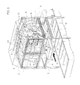
- the washing device of the drawer-like cages A essentially comprises a rotatable hollow drum 1 generally cylindrical, elongated and with a horizontal axis indicated by X, which is contained within a stationary protective casing 2, carried by a supporting frame 7 above a collecting tank 8 of the washing liquid and impurities coming from the drawer-like cages A.
- This tank 8 is conveniently provided with a grid filter and decantation sectors (not shown) to facilitate the separation of the solid residues from the washing liquid, for example, consisting of a mixture of water and sodium hydroxide, heated to about 90°C, which may be continuously recirculated in this way.
- the rotatable drum 1 is driven in rotation in the manner explained below.
- the casing 2 is open at the bottom and on one side delimits an inlet 3 and on the opposite side an outlet 4 of the drawer-like cages A relative to the rotatable drum 1.
- the inlet 3 and the outlet 4 are mutually offset along the X axis by a magnitude equal to at least twice the width of a drawer-like cage A, measured between its opposite sides C. Therefore, the length of the rotatable drum 1 is also equal to at least twice the width of a drawer-like cage A.
- the rotatable drum 1 has four radial arms 6 at each end, angularly equidistant between each other, and corresponding radial arms 6 of the two ends are interconnected axially by respective shoes 9 configured to temporarily engage the opposite sides D of each drawer-like cage A in a slidable manner, introducing them, in turn, through the inlet 3 in the rotatable drum 1.
- the drawer-like cages A are aligned with the inlet 3 along a horizontal row.
- the support frame 7 should therefore be shaped in a manner suited for this purpose and equipped with appropriate column-guides of the drawer-like cages upstream of the inlet 3 and downstream of the outlet 4.
- the drawer-like cages A are continuously fed in the direction of the arrow Z, by means of a motorized conveyor T, to the inlet 3 where they are engaged and introduced into the rotatable drum 1 through a corresponding shoe 9.
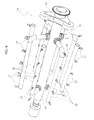
- Each shoe 9 comprises an articulated-lever kinematic mechanism 18 controlled by a stationary cam 19, configured to close the shoe 9 at the front side D of the drawer-like cage A, present at the inlet 3, drag it within the rotatable drum 1 held in rotation, and then reopen the shoe 9 after about 1 ⁇ 4 of a rotation, while keeping the side D slidably engaged with the shoe 9.
- the cam 19 controls the opening of the shoes 9 at the outlet 4, to allow the release and unloading of the drawer-like cages from the rotatable drum 1 at the end of washing.
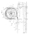
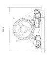
- the rotatable drum 1 is also provided at its ends with annular heads 10 supported in a rolling manner on rollers 20 carried by the frame 7, visible in Figure 4 .
- one of the annular heads 10 carries a gear driven in rotation by a motor 22.
- the rotation of the rotatable drum 1 by the motor 22 is continuous, as mentioned, possibly at variable speeds, and in an anticlockwise direction with reference to the drawings.
- the device is also configured to provide a generally helical roto-translational motion of said drawer-like cages, introduced, in turn, into the rotatable drum 1 and slidably engaged with the shoes 9, from the inlet 3 to the outlet 4.
- the magnitude of the rotatory component of the roto-translational motion is at least 360°.
- a cam member 11 is provided, most clearly seen in Figure 3 , formed by a generally helical stationary element configured to interact with the side of the drawer-like cage A introduced, in turn, into the rotatable drum 1 through the inlet 3.
- the cam member 11 applies a thrust to the drawer-like cage in a direction parallel to the X axis, causing the drawer-like cage to slide along the relative shoes 9 while it is simultaneously rotated by the rotatable drum 1, thus covering the helical route from the inlet 3 to the outlet 4, pushing the drawer-like cages A already present in the rotatable drum 1 along the same route.
- the cam member 11 is fixed to a sliding supporting structure 12 of the drawer-like cages A during their roto-translational motion, which coaxially encloses the rotatable drum 1 from the inlet 3 to the outlet 4.
- a plurality of stationary tubes 13 are provided, arranged outside the rotatable drum 1 and bearing sprinkling nozzles, and an assembly of rotatable sprayers 14, arranged coaxially within the rotatable drum 1.
- the spraying assembly 14 is only represented in part, for simplicity of illustration, it extends for the entire length of the rotatable drum 1.
- the spraying assembly 14 is formed of a central manifold 15, rotatably supported within at least one of the annular heads 10 of the rotatable drum 1 through a roller assembly 23, and driven in rotation by means of a motor 24.
- the central manifold 15 is connected to a plurality of tubes 16, which extend axially within the drum 1 and are provided with sprinkling nozzles 17.
- the operating cycle involves, during the continuous rotation of the rotatable drum 1, advancing of the row of drawer-like cages A towards the inlet 3.
- the front wall D of the drawer-like cages A which arrive one-by-one, is engaged by one of the shoes 9, dragged onto the supporting structure 12 and then connected at the rear wall D by the successive shoe 9.
- the drawer-like cage A starts to rotate with the rotatable drum 1, resting in a slidable manner on the structure 12, while it is simultaneously pushed laterally by the cam element 11, sliding along the two shoes 9 partially opened by the cam 19 and pushing the drawer-like cages A previously introduced into the rotatable drum 1.
- Each drawer-like cage A thus covers the 360° helical route up to the outlet 4 while it is sprayed by the washing liquid, from the outside by means of the tubes 13 and from inside by means of the assembly 14.
- the drawer-like cages A in turn positioned at the lower area of the rotatable drum 1, also receive the falling washing liquid sprayed on the drawer-like cages A above.
- the washing device according to the invention ensures complete and effective cleaning of the drawer-like cages, at the same time having a compact structural configuration, with a reduced size, as well as being more efficient from a functional point of view.
- the rotatable drum 1 may have a multiple length of the width of the drawer-like cages A, in such a way so that the cages, during their movement from the inlet 3 to the outlet 4, may complete more than one full rotation, and the shoes 9 can be of a greater or lesser number than four.
- a high-pressure pre-washing assembly (not shown) of the drawer-like cages A may be provided prior to the inlet 3 of the rotatable drum 1, prior to the inlet 3 of the rotatable drum 1, a high-pressure pre-washing assembly (not shown) of the drawer-like cages A may be provided prior to the inlet 3 of the rotatable drum 1, a high-pressure pre-washing assembly (not shown) of the drawer-like cages A may be provided prior to the inlet 3 of the rotatable drum 1, a high-pressure pre-washing assembly (not shown) of the drawer-like cages A may be provided prior to the inlet 3 of the rotatable drum 1, a high-pressure pre-washing assembly
Abstract
Description
- The present invention relates in general to containers for transporting live poultry from breeding farms to slaughterhouses, and particularly concerns the cleaning of these containers prior to their return from the slaughterhouse to the breeding farms for successive loading.
- Traditionally, for transferring poultry from breeding farms to slaughterhouses, transport units are used on-board trucks, including support frames within which superimposed stacks of drawer-like cages are inserted, in an extractable manner. Examples of such transport units are described and illustrated in documents
EP-1330952B1 andWO-2011/010329 , and the relative drawer-like cages are typically of the type described and illustrated in documentEP-0867113B1 . They have a quadrangular shape with a bottom wall and side walls provided with ventilation openings, and an open top for introducing and extracting the poultry. - Normally, these drawer-like cages are continuously moved between the breeding farm and the slaughterhouse, and vice versa, and thus need to be frequently cleaned from organic waste produced by the animals, also and above all in view of the fact that, if a flock is infected with salmonella or campylobacter, the risk of cross-contamination with other breeding farms must be absolutely avoided.
- Cleaning of the drawer-like cages must therefore be as effective and complete as possible.
- The systems currently in use envisage washing the drawer-like cages arranged in the same position only, typically horizontally with the open side facing upwards or upside-down with the open side facing downwards, or in a vertical position with a comb arrangement. These traditional systems are not able to ensure the required complete cleaning of all the walls of the drawer-like cages with their interstices, and in particular those corresponding to the ventilation openings on the side walls and on the bottom wall. Furthermore, these known systems envisage the movement of the drawer-like cages through the washing station by means of chain-movement assemblies which, in addition to involving cleaning problems themselves, do not allow the drawer-like cages to be kept stably in the most suitable predetermined position for receiving the washing jets.
- The object of the present invention is to overcome the aforesaid drawbacks and to make a device available for washing the drawer-like cages for transporting live poultry, which is able of ensuring the most complete and effective cleaning in a uniform and safe manner.
- According to the invention, this object is achieved thanks to a washing device whose unique characteristics are defined in the characterizing part of
claim 1, or rather comprising a rotatable drum with a horizontal axis having an inlet and an outlet, between which supports extend parallelly to the axis of the drum, mutually spaced-apart angularly and configured to temporarily engage the drawer-like cages in a slidable manner. Driving means are provided for continuously rotating the rotatable drum, cam means to provide, during rotation of said rotatable drum, a generally helical roto-translational motion to said drawer-like cages engaged with said supports, from said inlet to said outlet, and spraying means of the drawer-like cages with a washing liquid during said roto-translational motion thereof. - The washing liquid may consist of a mixture of sodium hydroxide and water, heated to a temperature of about 90°C, with the object of chemically eliminating organic substances removed from the drawer-like cages and to allow recirculation of the liquid.
- Conveniently, the magnitude of the rotatory component of the roto-translational motion of the drawer-like cages is at least 360°, and the supports consist of pairs of shoes configured to engage opposite sides of said drawer-like cages in a slidable manner.
- In a preferred embodiment of the invention, the slidable pairs of shoes are four in number and the rotatable drum has a length at least equal to twice the width of one drawer-like cage.
- Thanks to this solution idea, the drawer-like cages, sprayed in a plurality of different angular positions over a minimum of 360°, are washed completely and therefore entirely safe against the risk of contamination. The device according to the invention, in addition to being compact and of reduced size, allows the stable and accurate positioning and maintenance of the drawer-like cages in the most suitable positions for obtaining complete and effective washing.
- The invention also relates to a method for washing the drawer-like cages for transporting live poultry.
- The invention will now be described in detail with reference to the attached drawings, provided purely by way of non-limiting example, in which:
-
Figure 1 is a schematic and simplified perspective view of a washing device according to the invention, represented during its operation, -
Figure 2 is a view analogous toFigure 1 , in which some parts are omitted to highlight the operating components of the washing device, -
Figure 3 is a partial view in vertical cross-section of the washing device, -
Figure 4 is a partial side elevation view, on an enlarged scale, of a component of the washing device, -
Figure 5 is a perspective view, on an enlarged scale, of another component of the washing device, and -
Figure 6 is a perspective view of a further component of the washing device. - Referring to the drawings, the washing device according to the invention is configured to operate with drawer-like cages for transporting live poultry, indicated by A, for example, of the type described and illustrated in the document cited above,
EP-0867113B1 . Each drawer-like cage A consists of a body of molded plastic material of a quadrangular shape, more precisely rectangular, open at the top and having a bottom wall B, and two pairs of opposite side walls indicated, respectively, by C and D. Both the bottom wall B and the side walls C, D are normally formed with ventilation openings, not shown for simplicity of illustration. - The washing device of the drawer-like cages A essentially comprises a rotatable
hollow drum 1 generally cylindrical, elongated and with a horizontal axis indicated by X, which is contained within a stationaryprotective casing 2, carried by a supportingframe 7 above a collectingtank 8 of the washing liquid and impurities coming from the drawer-like cages A. Thistank 8 is conveniently provided with a grid filter and decantation sectors (not shown) to facilitate the separation of the solid residues from the washing liquid, for example, consisting of a mixture of water and sodium hydroxide, heated to about 90°C, which may be continuously recirculated in this way. - The
rotatable drum 1 is driven in rotation in the manner explained below. - The
casing 2 is open at the bottom and on one side delimits aninlet 3 and on the opposite side anoutlet 4 of the drawer-like cages A relative to therotatable drum 1. For the reasons which will become apparent below, theinlet 3 and theoutlet 4 are mutually offset along the X axis by a magnitude equal to at least twice the width of a drawer-like cage A, measured between its opposite sides C. Therefore, the length of therotatable drum 1 is also equal to at least twice the width of a drawer-like cage A. - The
rotatable drum 1 has fourradial arms 6 at each end, angularly equidistant between each other, and correspondingradial arms 6 of the two ends are interconnected axially byrespective shoes 9 configured to temporarily engage the opposite sides D of each drawer-like cage A in a slidable manner, introducing them, in turn, through theinlet 3 in therotatable drum 1. - As is illustrated in detail in
Figure 3 , the drawer-like cages A are aligned with theinlet 3 along a horizontal row. Thesupport frame 7 should therefore be shaped in a manner suited for this purpose and equipped with appropriate column-guides of the drawer-like cages upstream of theinlet 3 and downstream of theoutlet 4. - The drawer-like cages A are continuously fed in the direction of the arrow Z, by means of a motorized conveyor T, to the
inlet 3 where they are engaged and introduced into therotatable drum 1 through acorresponding shoe 9. - Each
shoe 9 comprises an articulated-lever kinematic mechanism 18 controlled by astationary cam 19, configured to close theshoe 9 at the front side D of the drawer-like cage A, present at theinlet 3, drag it within therotatable drum 1 held in rotation, and then reopen theshoe 9 after about ¼ of a rotation, while keeping the side D slidably engaged with theshoe 9. Thecam 19 controls the opening of theshoes 9 at theoutlet 4, to allow the release and unloading of the drawer-like cages from therotatable drum 1 at the end of washing. - The
rotatable drum 1 is also provided at its ends withannular heads 10 supported in a rolling manner onrollers 20 carried by theframe 7, visible inFigure 4 . As is also illustrated in detail inFigure 4 , one of theannular heads 10 carries a gear driven in rotation by amotor 22. During operation, the rotation of therotatable drum 1 by themotor 22 is continuous, as mentioned, possibly at variable speeds, and in an anticlockwise direction with reference to the drawings. - The device is also configured to provide a generally helical roto-translational motion of said drawer-like cages, introduced, in turn, into the
rotatable drum 1 and slidably engaged with theshoes 9, from theinlet 3 to theoutlet 4. The magnitude of the rotatory component of the roto-translational motion is at least 360°. - To this effect, a
cam member 11 is provided, most clearly seen inFigure 3 , formed by a generally helical stationary element configured to interact with the side of the drawer-like cage A introduced, in turn, into therotatable drum 1 through theinlet 3. Thecam member 11 applies a thrust to the drawer-like cage in a direction parallel to the X axis, causing the drawer-like cage to slide along therelative shoes 9 while it is simultaneously rotated by therotatable drum 1, thus covering the helical route from theinlet 3 to theoutlet 4, pushing the drawer-like cages A already present in therotatable drum 1 along the same route. - The
cam member 11 is fixed to a sliding supportingstructure 12 of the drawer-like cages A during their roto-translational motion, which coaxially encloses therotatable drum 1 from theinlet 3 to theoutlet 4. - For washing the drawer-like cages A during their roto-translational motion in the
rotatable drum 1, a plurality ofstationary tubes 13 are provided, arranged outside therotatable drum 1 and bearing sprinkling nozzles, and an assembly ofrotatable sprayers 14, arranged coaxially within therotatable drum 1. Although inFigures 1 and2 thespraying assembly 14 is only represented in part, for simplicity of illustration, it extends for the entire length of therotatable drum 1. - As is illustrated in detail in
Figures 4 and6 , thespraying assembly 14 is formed of acentral manifold 15, rotatably supported within at least one of theannular heads 10 of therotatable drum 1 through aroller assembly 23, and driven in rotation by means of amotor 24. Thecentral manifold 15 is connected to a plurality oftubes 16, which extend axially within thedrum 1 and are provided withsprinkling nozzles 17. - The operating cycle involves, during the continuous rotation of the
rotatable drum 1, advancing of the row of drawer-like cages A towards theinlet 3. The front wall D of the drawer-like cages A, which arrive one-by-one, is engaged by one of theshoes 9, dragged onto the supportingstructure 12 and then connected at the rear wall D by thesuccessive shoe 9. In this way, the drawer-like cage A starts to rotate with therotatable drum 1, resting in a slidable manner on thestructure 12, while it is simultaneously pushed laterally by thecam element 11, sliding along the twoshoes 9 partially opened by thecam 19 and pushing the drawer-like cages A previously introduced into therotatable drum 1. Each drawer-like cage A thus covers the 360° helical route up to theoutlet 4 while it is sprayed by the washing liquid, from the outside by means of thetubes 13 and from inside by means of theassembly 14. The drawer-like cages A, in turn positioned at the lower area of therotatable drum 1, also receive the falling washing liquid sprayed on the drawer-like cages A above. - It is apparent from the above description that the washing device according to the invention ensures complete and effective cleaning of the drawer-like cages, at the same time having a compact structural configuration, with a reduced size, as well as being more efficient from a functional point of view.
- Of course, the details of construction and the embodiments may be varied widely with respect to those described and illustrated, without departing from the scope of the present invention as defined by the following claims. Thus, for example, the
rotatable drum 1 may have a multiple length of the width of the drawer-like cages A, in such a way so that the cages, during their movement from theinlet 3 to theoutlet 4, may complete more than one full rotation, and theshoes 9 can be of a greater or lesser number than four. Furthermore, prior to theinlet 3 of therotatable drum 1, a high-pressure pre-washing assembly (not shown) of the drawer-like cages A may be provided.
Claims (17)
- Device for washing containers for transporting live poultry, wherein said containers consist of drawer-like cages (A) having a quadrangular shape with a bottom wall (B), side walls (C, D) and an open top, characterized in that it comprises:- a drum (1) rotatable around a horizontal axis (X) and having an inlet (3) and an outlet (4) between which supports (9) extend parallelly to the axis (X) of the drum (1) which are mutually spaced-apart angularly and configured to temporarily engage the drawer-like cages (A) in a slidable manner,- driving means (22) for continuously rotating said rotatable drum (1),- cam means (11) to provide, during rotation of said rotatable drum (1), a generally helical roto-translational motion of said drawer-like cages (A), engaged with said supports (9), from said inlet (3) to said outlet (4),- spraying means (13, 14) of the drawer-like cages (A) with a washing liquid during said roto-translational motion thereof.
- Device according to claim 1, characterized in that the magnitude of the rotatable component of the roto-translational motion of the drawer-like cages (A) is at least 360°.
- Device according to claims 1 or 2, characterized in that said supports consist of pairs of shoes (9) configured to slidably engage two opposite side walls (D) of said drawer-like cages (A).
- Device according to claim 3, characterized in that said pairs of shoes (9) are four in number.
- Device according to any one of the preceding claims, characterized in that said rotatable drum (1) has a length at least equal to twice the width of one drawer-like cage (A).
- Device according to any one of the preceding claims, characterized in that said cam means include a generally helical stationary element (11) designed to interact with said drawer-like cages (A) by applying a thrust in a direction parallel to the axis (X) of the rotatable drum (1).
- Device according to claims 3 or 4, characterized in that introducing the drawer-like cages (A) into the rotatable drum (1) is carried out upon entrainment thereof by said shoes (9), which are provided with opening and closing kinematic mechanisms (18), operated by a stationary cam (19) during rotation of the rotatable drum (1).
- Device according to any one of the preceding claims, characterized in that said rotatable drum (1) is arranged within a stationary structure (12) providing sliding bearing of said drawer-like cages (A) during the roto-translational motion thereof.
- Device according to any one of the preceding claims, characterized in that said spraying means (13) are arranged externally to said rotatable drum (1).
- Device according to claim 9, characterized in that said spraying means (14) are also arranged internally to said rotatable drum (1).
- Device according to claim 10, characterized in that said spraying means comprise a rotatable assembly (14) formed of a central manifold (15) connected to a number of tubes (16) extending axially within the rotatable drum (1) and provided with sprinkling nozzles (17).
- Device according to any one of the preceding claims, characterized in that a collecting tank (8) of the washing liquid and of the material removed from the drawer-like cages (A) is arranged beneath said rotatable drum (1) and is provided with a filter and decantation sectors in order to enable re-circulation of the washing liquid towards said spraying means (13, 14).
- Method for washing containers for transporting live poultry consisting of drawer-like cages (A) having a quadrangular shape, characterized in that it consists of successively introducing said drawer-like cages (A) into a rotatable drum (1) having a horizontal axis (X), an inlet (3) and an outlet (4), continuously rotatably driving said rotatable drum (1), moving said drawer-like cages (A) according to a generally helical roto-translational motion from the inlet (3) to the outlet (4) of the rotatable drum (1), and spraying said drawer-like cages (A) with a washing liquid during the roto-translational motion thereof.
- Method according to claim 13, characterized in that the magnitude of the rotatable component of the roto-translational motion of the drawer-like cages (A) is at least 360°.
- Method according to claims 13 or 14, characterized in that introducing the drawer-like cages (A) into the rotatable drum (1) is carried out during advancing of said drawer-like cages (A) aligned along a horizontal row at the inlet (3) of the drum (1).
- Method according to any one of claims 13 to 15, characterized in that the drawer-like cages (A) are sprayed both externally and internally with the washing liquid.
- Method according to any one of claims 13 to 16, characterized in that the washing liquid is a heated mixture of sodium hydroxide and water.
Priority Applications (1)
| Application Number | Priority Date | Filing Date | Title |
|---|---|---|---|
| PL15152598T PL2902121T3 (en) | 2014-01-30 | 2015-01-27 | Device for washing containers for transporting live poultry |
Applications Claiming Priority (1)
| Application Number | Priority Date | Filing Date | Title |
|---|---|---|---|
| ITTO20140070 | 2014-01-30 |
Publications (2)
| Publication Number | Publication Date |
|---|---|
| EP2902121A1 true EP2902121A1 (en) | 2015-08-05 |
| EP2902121B1 EP2902121B1 (en) | 2019-02-20 |
Family
ID=50342422
Family Applications (1)
| Application Number | Title | Priority Date | Filing Date |
|---|---|---|---|
| EP15152598.7A Active EP2902121B1 (en) | 2014-01-30 | 2015-01-27 | Device for washing containers for transporting live poultry |
Country Status (5)
| Country | Link |
|---|---|
| US (1) | US10610908B2 (en) |
| EP (1) | EP2902121B1 (en) |
| DK (1) | DK2902121T3 (en) |
| PL (1) | PL2902121T3 (en) |
| WO (1) | WO2015114511A1 (en) |
Cited By (2)
| Publication number | Priority date | Publication date | Assignee | Title |
|---|---|---|---|---|
| CN107416282A (en) * | 2017-04-26 | 2017-12-01 | 重庆乐嚼食品有限公司 | Tin can cleans transport mechanism |
| CN111283909A (en) * | 2020-02-20 | 2020-06-16 | 倪美锦 | Clinical laboratory's urine detects waste refuse treatment ware |
Families Citing this family (1)
| Publication number | Priority date | Publication date | Assignee | Title |
|---|---|---|---|---|
| WO2015114511A1 (en) | 2014-01-30 | 2015-08-06 | Massimo Zanotti | Device for washing containers for transporting live poultry |
Citations (7)
| Publication number | Priority date | Publication date | Assignee | Title |
|---|---|---|---|---|
| FR2545012A1 (en) * | 1983-04-28 | 1984-11-02 | Teka Maschinenbau Gmbh | CONTAINER CLEANING DEVICE |
| DE9306403U1 (en) * | 1993-04-28 | 1993-08-12 | Wiegleb, Ludwig, 59427 Unna, De | |
| US6132509A (en) * | 1997-08-13 | 2000-10-17 | Kuschnereit; Gene L. | Transportable wash and paint facility |
| EP0867113B1 (en) | 1997-03-12 | 2002-05-29 | GIORDANO POULTRY-PLAST S.p.A. | Cage for transporting poultry |
| EP1330952B1 (en) | 2002-01-23 | 2005-08-17 | GIORDANO POULTRY-PLAST S.p.A. | A method and system for transporting live poultry |
| WO2011010329A1 (en) | 2009-07-20 | 2011-01-27 | Linco Italia S.R.L. | Transporting unit for live poultry on board a truck |
| EP2397237A2 (en) * | 2010-06-16 | 2011-12-21 | Helmut Peböck | Device for cleaning containers |
Family Cites Families (3)
| Publication number | Priority date | Publication date | Assignee | Title |
|---|---|---|---|---|
| US5566697A (en) * | 1995-02-07 | 1996-10-22 | Intercontinental Chemical Corporation | Oscillator screen cleaning apparatus |
| DE19533462A1 (en) * | 1995-09-09 | 1997-03-13 | Ruediger Haaga Gmbh | Container filler device for foaming liquid |
| WO2015114511A1 (en) | 2014-01-30 | 2015-08-06 | Massimo Zanotti | Device for washing containers for transporting live poultry |
-
2015
- 2015-01-27 WO PCT/IB2015/050599 patent/WO2015114511A1/en active Application Filing
- 2015-01-27 PL PL15152598T patent/PL2902121T3/en unknown
- 2015-01-27 DK DK15152598.7T patent/DK2902121T3/en active
- 2015-01-27 EP EP15152598.7A patent/EP2902121B1/en active Active
- 2015-01-30 US US14/610,225 patent/US10610908B2/en active Active
Patent Citations (7)
| Publication number | Priority date | Publication date | Assignee | Title |
|---|---|---|---|---|
| FR2545012A1 (en) * | 1983-04-28 | 1984-11-02 | Teka Maschinenbau Gmbh | CONTAINER CLEANING DEVICE |
| DE9306403U1 (en) * | 1993-04-28 | 1993-08-12 | Wiegleb, Ludwig, 59427 Unna, De | |
| EP0867113B1 (en) | 1997-03-12 | 2002-05-29 | GIORDANO POULTRY-PLAST S.p.A. | Cage for transporting poultry |
| US6132509A (en) * | 1997-08-13 | 2000-10-17 | Kuschnereit; Gene L. | Transportable wash and paint facility |
| EP1330952B1 (en) | 2002-01-23 | 2005-08-17 | GIORDANO POULTRY-PLAST S.p.A. | A method and system for transporting live poultry |
| WO2011010329A1 (en) | 2009-07-20 | 2011-01-27 | Linco Italia S.R.L. | Transporting unit for live poultry on board a truck |
| EP2397237A2 (en) * | 2010-06-16 | 2011-12-21 | Helmut Peböck | Device for cleaning containers |
Cited By (2)
| Publication number | Priority date | Publication date | Assignee | Title |
|---|---|---|---|---|
| CN107416282A (en) * | 2017-04-26 | 2017-12-01 | 重庆乐嚼食品有限公司 | Tin can cleans transport mechanism |
| CN111283909A (en) * | 2020-02-20 | 2020-06-16 | 倪美锦 | Clinical laboratory's urine detects waste refuse treatment ware |
Also Published As
| Publication number | Publication date |
|---|---|
| PL2902121T3 (en) | 2019-10-31 |
| WO2015114511A1 (en) | 2015-08-06 |
| US20150209844A1 (en) | 2015-07-30 |
| DK2902121T3 (en) | 2019-04-29 |
| US10610908B2 (en) | 2020-04-07 |
| EP2902121B1 (en) | 2019-02-20 |
Similar Documents
| Publication | Publication Date | Title |
|---|---|---|
| US10610908B2 (en) | Device for washing containers for transporting live poultry | |
| EP2967090B9 (en) | Support device for poultry processing device | |
| CN108617547B (en) | Chicken grabbing and distributing device and method for broiler chicken separation breeding in large chicken farm | |
| EP2641095B1 (en) | Air-conditioning space for storing samples in a time-controlled manner and method for storing samples in a time-controlled manner | |
| EP2927163A1 (en) | Vertical conveyor, sample distribution system and laboratory automation system | |
| US9901951B2 (en) | Dip coating system comprising a device for rotating the article to be treated | |
| EP2624684B1 (en) | Device and method for cleaning a support structure for poultry holders | |
| RU2533039C1 (en) | Extractor of seeds from gourds fruits, mainly pumpkin | |
| EP2845487A1 (en) | An automatic machine for removal of seasoning lard paste | |
| US10905106B2 (en) | Vehicle for moving cages for poultry or the like | |
| DE1652268B2 (en) | MACHINE FOR SPIN BLASTING WORK PIECES | |
| EP2818424B1 (en) | System and method for cleaning rotatable elements of a labelling unit | |
| EP2902122A1 (en) | Device for washing containers for transporting live poultry | |
| WO2004018298A1 (en) | Sterilization device for caps of beverage containers | |
| DE102004027576A1 (en) | Bleeding station for stunned cattle, for slaughter, has bleeding sets moving on a continuous path parallel to the cattle conveyor to extract blood to be collected in vessels with an anticoagulant | |
| CN101932518B (en) | Treatment system for the surface treatment of items, particularly vehicle bodies | |
| EP2100515B1 (en) | Enrober machine | |
| DE102008010421A1 (en) | Output unit for self service removal of bakery products such as biscuits, has goods container receiving supply quantity of product sections which are guided to area of removal opening of inner chamber containing supply quantity | |
| ITPR20130073A1 (en) | COOKER DEVICE FOR TRANSFER, HANDLING AND COOKING, AT LEAST PARTIAL, OF FOOD PRODUCTS | |
| DE2458783A1 (en) | SAMPLER | |
| RU133685U1 (en) | TRANSPORTER FOR UNLOADING BIRDS BY TIERS FROM CELL BATTERIES | |
| DE3319544A1 (en) | Dip-coating installation | |
| UA114210U (en) | CELL BATTERY FOR BROILER GROWING | |
| DE977174C (en) | Device for dispensing rows of bottles from cleaning machines | |
| DE594611C (en) |
Legal Events
| Date | Code | Title | Description |
|---|---|---|---|
| PUAI | Public reference made under article 153(3) epc to a published international application that has entered the european phase |
Free format text: ORIGINAL CODE: 0009012 |
|
| 17P | Request for examination filed |
Effective date: 20150127 |
|
| AK | Designated contracting states |
Kind code of ref document: A1 Designated state(s): AL AT BE BG CH CY CZ DE DK EE ES FI FR GB GR HR HU IE IS IT LI LT LU LV MC MK MT NL NO PL PT RO RS SE SI SK SM TR |
|
| AX | Request for extension of the european patent |
Extension state: BA ME |
|
| 17P | Request for examination filed |
Effective date: 20160205 |
|
| RBV | Designated contracting states (corrected) |
Designated state(s): AL AT BE BG CH CY CZ DE DK EE ES FI FR GB GR HR HU IE IS IT LI LT LU LV MC MK MT NL NO PL PT RO RS SE SI SK SM TR |
|
| GRAP | Despatch of communication of intention to grant a patent |
Free format text: ORIGINAL CODE: EPIDOSNIGR1 |
|
| STAA | Information on the status of an ep patent application or granted ep patent |
Free format text: STATUS: GRANT OF PATENT IS INTENDED |
|
| INTG | Intention to grant announced |
Effective date: 20180913 |
|
| GRAS | Grant fee paid |
Free format text: ORIGINAL CODE: EPIDOSNIGR3 |
|
| GRAA | (expected) grant |
Free format text: ORIGINAL CODE: 0009210 |
|
| STAA | Information on the status of an ep patent application or granted ep patent |
Free format text: STATUS: THE PATENT HAS BEEN GRANTED |
|
| AK | Designated contracting states |
Kind code of ref document: B1 Designated state(s): AL AT BE BG CH CY CZ DE DK EE ES FI FR GB GR HR HU IE IS IT LI LT LU LV MC MK MT NL NO PL PT RO RS SE SI SK SM TR |
|
| REG | Reference to a national code |
Ref country code: GB Ref legal event code: FG4D |
|
| REG | Reference to a national code |
Ref country code: CH Ref legal event code: EP |
|
| REG | Reference to a national code |
Ref country code: DE Ref legal event code: R096 Ref document number: 602015024712 Country of ref document: DE |
|
| REG | Reference to a national code |
Ref country code: AT Ref legal event code: REF Ref document number: 1097502 Country of ref document: AT Kind code of ref document: T Effective date: 20190315 |
|
| REG | Reference to a national code |
Ref country code: IE Ref legal event code: FG4D |
|
| REG | Reference to a national code |
Ref country code: DK Ref legal event code: T3 Effective date: 20190423 |
|
| REG | Reference to a national code |
Ref country code: NL Ref legal event code: FP |
|
| REG | Reference to a national code |
Ref country code: LT Ref legal event code: MG4D |
|
| PG25 | Lapsed in a contracting state [announced via postgrant information from national office to epo] |
Ref country code: LT Free format text: LAPSE BECAUSE OF FAILURE TO SUBMIT A TRANSLATION OF THE DESCRIPTION OR TO PAY THE FEE WITHIN THE PRESCRIBED TIME-LIMIT Effective date: 20190220 Ref country code: SE Free format text: LAPSE BECAUSE OF FAILURE TO SUBMIT A TRANSLATION OF THE DESCRIPTION OR TO PAY THE FEE WITHIN THE PRESCRIBED TIME-LIMIT Effective date: 20190220 Ref country code: PT Free format text: LAPSE BECAUSE OF FAILURE TO SUBMIT A TRANSLATION OF THE DESCRIPTION OR TO PAY THE FEE WITHIN THE PRESCRIBED TIME-LIMIT Effective date: 20190620 Ref country code: NO Free format text: LAPSE BECAUSE OF FAILURE TO SUBMIT A TRANSLATION OF THE DESCRIPTION OR TO PAY THE FEE WITHIN THE PRESCRIBED TIME-LIMIT Effective date: 20190520 Ref country code: FI Free format text: LAPSE BECAUSE OF FAILURE TO SUBMIT A TRANSLATION OF THE DESCRIPTION OR TO PAY THE FEE WITHIN THE PRESCRIBED TIME-LIMIT Effective date: 20190220 |
|
| PG25 | Lapsed in a contracting state [announced via postgrant information from national office to epo] |
Ref country code: RS Free format text: LAPSE BECAUSE OF FAILURE TO SUBMIT A TRANSLATION OF THE DESCRIPTION OR TO PAY THE FEE WITHIN THE PRESCRIBED TIME-LIMIT Effective date: 20190220 Ref country code: LV Free format text: LAPSE BECAUSE OF FAILURE TO SUBMIT A TRANSLATION OF THE DESCRIPTION OR TO PAY THE FEE WITHIN THE PRESCRIBED TIME-LIMIT Effective date: 20190220 Ref country code: HR Free format text: LAPSE BECAUSE OF FAILURE TO SUBMIT A TRANSLATION OF THE DESCRIPTION OR TO PAY THE FEE WITHIN THE PRESCRIBED TIME-LIMIT Effective date: 20190220 Ref country code: GR Free format text: LAPSE BECAUSE OF FAILURE TO SUBMIT A TRANSLATION OF THE DESCRIPTION OR TO PAY THE FEE WITHIN THE PRESCRIBED TIME-LIMIT Effective date: 20190521 Ref country code: BG Free format text: LAPSE BECAUSE OF FAILURE TO SUBMIT A TRANSLATION OF THE DESCRIPTION OR TO PAY THE FEE WITHIN THE PRESCRIBED TIME-LIMIT Effective date: 20190520 Ref country code: IS Free format text: LAPSE BECAUSE OF FAILURE TO SUBMIT A TRANSLATION OF THE DESCRIPTION OR TO PAY THE FEE WITHIN THE PRESCRIBED TIME-LIMIT Effective date: 20190620 |
|
| REG | Reference to a national code |
Ref country code: AT Ref legal event code: MK05 Ref document number: 1097502 Country of ref document: AT Kind code of ref document: T Effective date: 20190220 |
|
| PG25 | Lapsed in a contracting state [announced via postgrant information from national office to epo] |
Ref country code: EE Free format text: LAPSE BECAUSE OF FAILURE TO SUBMIT A TRANSLATION OF THE DESCRIPTION OR TO PAY THE FEE WITHIN THE PRESCRIBED TIME-LIMIT Effective date: 20190220 Ref country code: SK Free format text: LAPSE BECAUSE OF FAILURE TO SUBMIT A TRANSLATION OF THE DESCRIPTION OR TO PAY THE FEE WITHIN THE PRESCRIBED TIME-LIMIT Effective date: 20190220 Ref country code: CZ Free format text: LAPSE BECAUSE OF FAILURE TO SUBMIT A TRANSLATION OF THE DESCRIPTION OR TO PAY THE FEE WITHIN THE PRESCRIBED TIME-LIMIT Effective date: 20190220 Ref country code: AL Free format text: LAPSE BECAUSE OF FAILURE TO SUBMIT A TRANSLATION OF THE DESCRIPTION OR TO PAY THE FEE WITHIN THE PRESCRIBED TIME-LIMIT Effective date: 20190220 Ref country code: ES Free format text: LAPSE BECAUSE OF FAILURE TO SUBMIT A TRANSLATION OF THE DESCRIPTION OR TO PAY THE FEE WITHIN THE PRESCRIBED TIME-LIMIT Effective date: 20190220 Ref country code: RO Free format text: LAPSE BECAUSE OF FAILURE TO SUBMIT A TRANSLATION OF THE DESCRIPTION OR TO PAY THE FEE WITHIN THE PRESCRIBED TIME-LIMIT Effective date: 20190220 |
|
| REG | Reference to a national code |
Ref country code: DE Ref legal event code: R097 Ref document number: 602015024712 Country of ref document: DE |
|
| PG25 | Lapsed in a contracting state [announced via postgrant information from national office to epo] |
Ref country code: SM Free format text: LAPSE BECAUSE OF FAILURE TO SUBMIT A TRANSLATION OF THE DESCRIPTION OR TO PAY THE FEE WITHIN THE PRESCRIBED TIME-LIMIT Effective date: 20190220 |
|
| PLBE | No opposition filed within time limit |
Free format text: ORIGINAL CODE: 0009261 |
|
| STAA | Information on the status of an ep patent application or granted ep patent |
Free format text: STATUS: NO OPPOSITION FILED WITHIN TIME LIMIT |
|
| PG25 | Lapsed in a contracting state [announced via postgrant information from national office to epo] |
Ref country code: AT Free format text: LAPSE BECAUSE OF FAILURE TO SUBMIT A TRANSLATION OF THE DESCRIPTION OR TO PAY THE FEE WITHIN THE PRESCRIBED TIME-LIMIT Effective date: 20190220 |
|
| 26N | No opposition filed |
Effective date: 20191121 |
|
| PG25 | Lapsed in a contracting state [announced via postgrant information from national office to epo] |
Ref country code: SI Free format text: LAPSE BECAUSE OF FAILURE TO SUBMIT A TRANSLATION OF THE DESCRIPTION OR TO PAY THE FEE WITHIN THE PRESCRIBED TIME-LIMIT Effective date: 20190220 |
|
| PG25 | Lapsed in a contracting state [announced via postgrant information from national office to epo] |
Ref country code: TR Free format text: LAPSE BECAUSE OF FAILURE TO SUBMIT A TRANSLATION OF THE DESCRIPTION OR TO PAY THE FEE WITHIN THE PRESCRIBED TIME-LIMIT Effective date: 20190220 |
|
| PG25 | Lapsed in a contracting state [announced via postgrant information from national office to epo] |
Ref country code: MC Free format text: LAPSE BECAUSE OF FAILURE TO SUBMIT A TRANSLATION OF THE DESCRIPTION OR TO PAY THE FEE WITHIN THE PRESCRIBED TIME-LIMIT Effective date: 20190220 |
|
| REG | Reference to a national code |
Ref country code: CH Ref legal event code: PL |
|
| REG | Reference to a national code |
Ref country code: BE Ref legal event code: MM Effective date: 20200131 |
|
| PG25 | Lapsed in a contracting state [announced via postgrant information from national office to epo] |
Ref country code: LU Free format text: LAPSE BECAUSE OF NON-PAYMENT OF DUE FEES Effective date: 20200127 |
|
| PG25 | Lapsed in a contracting state [announced via postgrant information from national office to epo] |
Ref country code: LI Free format text: LAPSE BECAUSE OF NON-PAYMENT OF DUE FEES Effective date: 20200131 Ref country code: CH Free format text: LAPSE BECAUSE OF NON-PAYMENT OF DUE FEES Effective date: 20200131 Ref country code: BE Free format text: LAPSE BECAUSE OF NON-PAYMENT OF DUE FEES Effective date: 20200131 |
|
| PG25 | Lapsed in a contracting state [announced via postgrant information from national office to epo] |
Ref country code: IE Free format text: LAPSE BECAUSE OF NON-PAYMENT OF DUE FEES Effective date: 20200127 |
|
| PG25 | Lapsed in a contracting state [announced via postgrant information from national office to epo] |
Ref country code: MT Free format text: LAPSE BECAUSE OF FAILURE TO SUBMIT A TRANSLATION OF THE DESCRIPTION OR TO PAY THE FEE WITHIN THE PRESCRIBED TIME-LIMIT Effective date: 20190220 Ref country code: CY Free format text: LAPSE BECAUSE OF FAILURE TO SUBMIT A TRANSLATION OF THE DESCRIPTION OR TO PAY THE FEE WITHIN THE PRESCRIBED TIME-LIMIT Effective date: 20190220 |
|
| PG25 | Lapsed in a contracting state [announced via postgrant information from national office to epo] |
Ref country code: MK Free format text: LAPSE BECAUSE OF FAILURE TO SUBMIT A TRANSLATION OF THE DESCRIPTION OR TO PAY THE FEE WITHIN THE PRESCRIBED TIME-LIMIT Effective date: 20190220 |
|
| PGFP | Annual fee paid to national office [announced via postgrant information from national office to epo] |
Ref country code: FR Payment date: 20230113 Year of fee payment: 9 Ref country code: DK Payment date: 20230105 Year of fee payment: 9 |
|
| PGFP | Annual fee paid to national office [announced via postgrant information from national office to epo] |
Ref country code: PL Payment date: 20230102 Year of fee payment: 9 Ref country code: IT Payment date: 20230105 Year of fee payment: 9 Ref country code: GB Payment date: 20230104 Year of fee payment: 9 Ref country code: DE Payment date: 20230124 Year of fee payment: 9 |
|
| PGFP | Annual fee paid to national office [announced via postgrant information from national office to epo] |
Ref country code: NL Payment date: 20230105 Year of fee payment: 9 |
|
| PGFP | Annual fee paid to national office [announced via postgrant information from national office to epo] |
Ref country code: NL Payment date: 20240103 Year of fee payment: 10 |