EP2901899B1 - Induction heating container - Google Patents
Induction heating container Download PDFInfo
- Publication number
- EP2901899B1 EP2901899B1 EP13842779.4A EP13842779A EP2901899B1 EP 2901899 B1 EP2901899 B1 EP 2901899B1 EP 13842779 A EP13842779 A EP 13842779A EP 2901899 B1 EP2901899 B1 EP 2901899B1
- Authority
- EP
- European Patent Office
- Prior art keywords
- induction
- heat
- main body
- heat generator
- conductor layer
- Prior art date
- Legal status (The legal status is an assumption and is not a legal conclusion. Google has not performed a legal analysis and makes no representation as to the accuracy of the status listed.)
- Active
Links
- 230000006698 induction Effects 0.000 title claims description 113
- 238000010438 heat treatment Methods 0.000 title claims description 87
- 239000004020 conductor Substances 0.000 claims description 44
- 230000002093 peripheral effect Effects 0.000 claims description 20
- 239000012811 non-conductive material Substances 0.000 claims description 8
- 238000007789 sealing Methods 0.000 claims description 8
- 238000010411 cooking Methods 0.000 claims description 4
- 239000010410 layer Substances 0.000 description 48
- 239000007788 liquid Substances 0.000 description 10
- 238000005516 engineering process Methods 0.000 description 8
- 229920005989 resin Polymers 0.000 description 8
- 239000011347 resin Substances 0.000 description 8
- XLYOFNOQVPJJNP-UHFFFAOYSA-N water Substances O XLYOFNOQVPJJNP-UHFFFAOYSA-N 0.000 description 7
- XEEYBQQBJWHFJM-UHFFFAOYSA-N Iron Chemical compound [Fe] XEEYBQQBJWHFJM-UHFFFAOYSA-N 0.000 description 6
- 239000000463 material Substances 0.000 description 6
- 229910052782 aluminium Inorganic materials 0.000 description 5
- XAGFODPZIPBFFR-UHFFFAOYSA-N aluminium Chemical compound [Al] XAGFODPZIPBFFR-UHFFFAOYSA-N 0.000 description 5
- 238000009835 boiling Methods 0.000 description 4
- 239000011888 foil Substances 0.000 description 4
- 229920003002 synthetic resin Polymers 0.000 description 4
- 239000000057 synthetic resin Substances 0.000 description 4
- 230000000694 effects Effects 0.000 description 3
- 229910052742 iron Inorganic materials 0.000 description 3
- 229910052751 metal Inorganic materials 0.000 description 3
- 239000002184 metal Substances 0.000 description 3
- 238000013021 overheating Methods 0.000 description 3
- -1 polyethylene terephthalate Polymers 0.000 description 3
- PXHVJJICTQNCMI-UHFFFAOYSA-N Nickel Chemical compound [Ni] PXHVJJICTQNCMI-UHFFFAOYSA-N 0.000 description 2
- 239000004743 Polypropylene Substances 0.000 description 2
- 239000004793 Polystyrene Substances 0.000 description 2
- 238000005452 bending Methods 0.000 description 2
- 230000005540 biological transmission Effects 0.000 description 2
- 238000004519 manufacturing process Methods 0.000 description 2
- 238000012986 modification Methods 0.000 description 2
- 230000004048 modification Effects 0.000 description 2
- BASFCYQUMIYNBI-UHFFFAOYSA-N platinum Chemical compound [Pt] BASFCYQUMIYNBI-UHFFFAOYSA-N 0.000 description 2
- 229920001155 polypropylene Polymers 0.000 description 2
- 229920002223 polystyrene Polymers 0.000 description 2
- RYGMFSIKBFXOCR-UHFFFAOYSA-N Copper Chemical compound [Cu] RYGMFSIKBFXOCR-UHFFFAOYSA-N 0.000 description 1
- 206010067482 No adverse event Diseases 0.000 description 1
- BQCADISMDOOEFD-UHFFFAOYSA-N Silver Chemical compound [Ag] BQCADISMDOOEFD-UHFFFAOYSA-N 0.000 description 1
- ATJFFYVFTNAWJD-UHFFFAOYSA-N Tin Chemical compound [Sn] ATJFFYVFTNAWJD-UHFFFAOYSA-N 0.000 description 1
- HCHKCACWOHOZIP-UHFFFAOYSA-N Zinc Chemical compound [Zn] HCHKCACWOHOZIP-UHFFFAOYSA-N 0.000 description 1
- 239000000853 adhesive Substances 0.000 description 1
- 230000001070 adhesive effect Effects 0.000 description 1
- 229910045601 alloy Inorganic materials 0.000 description 1
- 239000000956 alloy Substances 0.000 description 1
- 230000015572 biosynthetic process Effects 0.000 description 1
- 230000015556 catabolic process Effects 0.000 description 1
- 229910017052 cobalt Inorganic materials 0.000 description 1
- 239000010941 cobalt Substances 0.000 description 1
- GUTLYIVDDKVIGB-UHFFFAOYSA-N cobalt atom Chemical compound [Co] GUTLYIVDDKVIGB-UHFFFAOYSA-N 0.000 description 1
- 238000011109 contamination Methods 0.000 description 1
- 229910052802 copper Inorganic materials 0.000 description 1
- 239000010949 copper Substances 0.000 description 1
- 230000005674 electromagnetic induction Effects 0.000 description 1
- 238000007667 floating Methods 0.000 description 1
- 239000011521 glass Substances 0.000 description 1
- PCHJSUWPFVWCPO-UHFFFAOYSA-N gold Chemical compound [Au] PCHJSUWPFVWCPO-UHFFFAOYSA-N 0.000 description 1
- 229910052737 gold Inorganic materials 0.000 description 1
- 239000010931 gold Substances 0.000 description 1
- 238000010030 laminating Methods 0.000 description 1
- 238000000465 moulding Methods 0.000 description 1
- 229910052759 nickel Inorganic materials 0.000 description 1
- 230000035515 penetration Effects 0.000 description 1
- 229910052697 platinum Inorganic materials 0.000 description 1
- 229920002647 polyamide Polymers 0.000 description 1
- 229920001225 polyester resin Polymers 0.000 description 1
- 229920000139 polyethylene terephthalate Polymers 0.000 description 1
- 239000005020 polyethylene terephthalate Substances 0.000 description 1
- 229920005672 polyolefin resin Polymers 0.000 description 1
- 230000002265 prevention Effects 0.000 description 1
- 239000011241 protective layer Substances 0.000 description 1
- 230000000630 rising effect Effects 0.000 description 1
- 239000004065 semiconductor Substances 0.000 description 1
- 229910052709 silver Inorganic materials 0.000 description 1
- 239000004332 silver Substances 0.000 description 1
- 239000002356 single layer Substances 0.000 description 1
- 238000009751 slip forming Methods 0.000 description 1
- 235000014347 soups Nutrition 0.000 description 1
- 239000004575 stone Substances 0.000 description 1
- 230000001629 suppression Effects 0.000 description 1
- 239000011135 tin Substances 0.000 description 1
- 229910052718 tin Inorganic materials 0.000 description 1
- 229910052725 zinc Inorganic materials 0.000 description 1
- 239000011701 zinc Substances 0.000 description 1
Images


Classifications
-
- H—ELECTRICITY
- H05—ELECTRIC TECHNIQUES NOT OTHERWISE PROVIDED FOR
- H05B—ELECTRIC HEATING; ELECTRIC LIGHT SOURCES NOT OTHERWISE PROVIDED FOR; CIRCUIT ARRANGEMENTS FOR ELECTRIC LIGHT SOURCES, IN GENERAL
- H05B6/00—Heating by electric, magnetic or electromagnetic fields
- H05B6/02—Induction heating
- H05B6/10—Induction heating apparatus, other than furnaces, for specific applications
- H05B6/12—Cooking devices
- H05B6/1209—Cooking devices induction cooking plates or the like and devices to be used in combination with them
-
- A—HUMAN NECESSITIES
- A47—FURNITURE; DOMESTIC ARTICLES OR APPLIANCES; COFFEE MILLS; SPICE MILLS; SUCTION CLEANERS IN GENERAL
- A47J—KITCHEN EQUIPMENT; COFFEE MILLS; SPICE MILLS; APPARATUS FOR MAKING BEVERAGES
- A47J36/00—Parts, details or accessories of cooking-vessels
- A47J36/02—Selection of specific materials, e.g. heavy bottoms with copper inlay or with insulating inlay
Definitions
- the present invention relates to an induction heating container provided with an induction heat generator in which heat is generated by joule heat caused by eddy current induced by a high-frequency magnetic field that occurs by an induction heating coil of an electromagnetic cooker or the like.
- a heating cooking device generally called as an electromagnetic cooker in which an object to be heated is heated by joule heat caused by eddy current induced by a high-frequency magnetic field that occurs by an induction heating coil provided inside has come to be widely used in common households.
- cookware used for heating an object to be heated by inducting heating by means of an electromagnetic cooker dedicated cookware made of a metal such as iron and enameled iron has conventionally been used.
- Patent Documents 1, 2 or the like a container for an electromagnetic cooker in which a heat generator made of a conductive material that generates heat by induction heating is attached to the container main body made of a non-conductive material.
- Patent Document 1 an induction heat generator is separated in the radial direction, the edge parts of the separated parts are abutted or superimposed to form a fuse function part.
- the fuse function part is caused to be broken selectively, whereby the container is prevented from being damaged by avoiding overheating.
- Such containers may encounter the following problem. Due to uneven heating or the like, a liquid object to be heated (e.g. water) in the container is suddenly heated locally, thereby causing bumping. As a result, the object to be heated is scattered to cause a user to get burned or to cause the surrounding area of an electromagnetic cooker to be contaminated.
- an induction heat generator is partially fixed to the inner bottom surface of a container main body, whereby linear adhesion parts extending in the circumferential direction of the heat generator are intermittently formed such that they are spaced from each other in the radial direction, whereby bumping that occurs at the time of heating a liquid object to be heated is suppressed.
- the present invention has been made in view of the above-mentioned circumstances, and is aimed at providing an induction heating container that can be used as an induction heating container in which an induction heat generator is attached to a container main body made of a non-conductive material and a liquid object to be heated accommodated therein is heated by an electromagnetic cocker or the like, and in such use, bumping at the time of heating a liquid object to be heated can be effectively prevented.
- the induction heating container of the present invention has a configuration according to claim 1.
- the induction heating container of the present invention can be safely used as an induction heating container with which bumping of a liquid object to be heated accommodated therein is effectively suppressed, whereby burning of a user or contamination of the surrounding area of an electromagnetic cooker can be prevented.
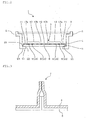
- FIG. 1 is a plan view showing the outline of the induction heating container according to this embodiment
- FIG. 2 is a schematic end elevation taken along the line A-A in FIG. 1 .
- the induction heating container 1 shown in FIGs. 1 and 2 is provided with a container main body 2 formed of a non-conductive material and an induction heat generator 3 attached to the inside of the container main body.
- the induction heat generator 3 is formed of a laminated body that includes a conductor layer 4 that generates heat when eddy current is induced by high-frequency magnetic field and a heat-seal layer 5 that has heat-sealing properties for the container main body 2.
- the induction heating container 1 is generally used on a commercially available electromagnetic cocker. Therefore, it is preferred that the sizes of the container main body 2 and the induction heat generator 3 be set according to the size of the heating coil provided in the electromagnetic cocker used.
- a general heating coil provided in a commercially available household electromagnetic cocker has an inner diameter of about 5 cm and an outer diameter of about 20 cm. In the case of an electromagnetic cocker for business use, a larger heating coil may be used. The size thereof is appropriately set according to the electromagnetic cocker that is supposed to be used.
- the container main body 2 is formed of a non-conductive material.
- a synthetic resin material such as a polystyrene-based resin such as polystyrene, a polyester-based resin such as polyethylene terephthalate, a polyolefin-based resin such as polypropylene, a polyamide-based resin or the like can preferably be used.
- the container main body 2 may be of a single layer structure or a multilayer structure obtained by combining these resins with one another or by combining these resins with other functional resins.
- paper, glass or the like can also be used as the non-conductive material, taking into consideration heat sealing with the heat-seal layer 5 in the induction heat generator 3, it is preferred that the inner surface thereof be coated with the above-mentioned synthetic resin.
- the shape of the container main body 2 is not limited to that shown in the figure. Various shapes can be selected such that the shape in the planer view is square, rectangular oblong, circle, elliptical or the like. In the shown example, in the planer view, the shape of the container main body 2 is almost square, and a step is provided in the vicinity of an opening at the upper end such that a tray 9 on which foodstuff is mounted can be supported or fitted. Although not particularly shown, a configuration is possible in which, on the tray 9 that is supported by or fitted to the container main body 2, another induction heating container 1 is stacked.
- the induction heat generator 3 has an almost circular flat plate form, and is attached to a bottom surface 20 of the container main body 2 in an almost circular flat plate form.
- a circle is most effective in respect of properties of eddy current induced.
- the shape of the container it may be square or elliptical.
- a rising part may be provided along the side wall of the container main body 2.
- the conductive material forming the conductor layer 4 of the induction heat generator 3 various conductive materials that generate heat by induction heating caused by high-frequency magnetic field such as a metal including aluminum, nickel, gold, silver, copper, platinum, iron, cobalt, tin and zinc, or alloys thereof can be used. More specifically, when aluminum is used as a conductive material, for example, the conductor layer 4 can be formed by using aluminum foil having a thickness of about 0.10 to 100 ⁇ m, more preferably 1 to 40 ⁇ m.
- the induction heat generator 3 when the induction heat generator 3 is attached to the container main body 2, it becomes easy to adapt the induction heat generator 3 to the shape of the container main body 2 by subjecting the induction heat generator 3 to three-dimensional processing, e.g. folding along a bottom surface 21 or the side wall of the container main body 2, or the like.
- the heat-seal layer 5 of the induction heat generator 3 is not particularly restricted as long as it has heat-sealing properties for the container main body 2.
- the heat-seal layer 5 can be appropriately selected according to a non-conductive material forming the container main body 2.
- a synthetic resin material similar to the synthetic resin material used for the container main body 2 can be used.
- polypropylene that is easy to be processed by molding, has good heat-sealing properties and an adequate heat resistance.
- the conductor layer 4 and the heat-seal layer 5 can be laminated directly or through an adequate adhesive by a known laminating technology.
- the induction heat generator 3 By configuring the induction heat generator 3 as a laminated body, since conventionally known technologies for producing a multilayer film or a multilayer sheet can be applied, the production of the induction heat generator 3 and the induction heating container 1 that is provided with the induction heat generator 3 is facilitated.
- a fuse function part 7 that is broken selectively under specific circumstances (such as empty boiling) is provided.
- Two fuse function parts 7 are radially provided on an extension of the center line that passes a shape center 8 of the induction heat generator 3 with a prescribed distance being provided from the shape center 8.
- the fuse function part 7 a technology disclosed in Patent Document 1 or JP-A-2010-044929 can be used, for example.
- the induction heat generator 3 is separated in the radial direction, and edges of the thus separated generator are abutted to each other or superimposed one on another to allow the conductor layers 4 are brought into contact and re-bonded.
- FIG. 3 which is a schematic end elevation view taken along line B-B in FIG. 1 , shows one example of such fuse function part 7.
- the edge part sides of the separated conductor layer 4 rises, and the edges thereof are aligned, superimposed one on another, and bonded.
- the heat-seal layer 5 in the corresponding part is peeled off.
- known technologies can be used; for example, a technology disclosed in JP-H07-296963 in which a narrow part in which the width in the radial direction becomes locally shortest is provided from the center to the outer periphery of the heat generator, whereby eddy current is concentrated in the narrow part to allow the temperature of the narrow part to be higher than that of other parts, a technology disclosed in JP-A-2007-330391 in which the radial direction of a heat generator is subjected to mountain folding processing in the radial direction to form a projection, and the projection is exposed from the liquid surface before other parts are exposed.
- an eddy current control part 6 that is formed by cutting the conductor layer 4 along the circumferential direction.
- a plurality of eddy current control parts 6 are provided such that they avoid the fuse function part 7 and that they are spaced from each other in the radial direction.
- the eddy current control parts 6 are provided by four cutting lines 13 in total in a region slightly nearer to the outer periphery of the induction heat generator 3 (a main heating area10, mentioned later).
- the edges of the cutting lines 13 that form the eddy current control part 6 serve as a starting point where bubbles are generated when an object to be heated such as water is boiled. Accordingly, at the time of boiling, a large amount of small bubbles is continuously generated as in the case where a boiling bubble stone is put, whereby an effect is exhibited that abrupt generation of large bubbles is prevented.
- the eddy current control part 6 controls the eddy current induced in the conductor layer 4, and enables uniform heating, whereby occurrence of bumping is suppressed.
- Eddy current is strongly induced in accordance with the shape of a heating coil provided in an electromagnetic cooker on which the induction heating container 1 is mounted.
- the current density distribution thereof is not uniform in the radial direction, and has a current density peak at a position slightly closer to the outer periphery than the center of the radial direction, and as a result, a corresponding position of the conductor layer 4 is strongly heated.
- the cutting line 13 that forms the eddy current control part 6 is, as shown in the schematic end elevation in FIG. 4(a) , obtained by cutting the conductor layer 4 of the laminated bodies forming the induction heat generator 3. No current is flown in a direction crossing the cutting line 13. By forming the cutting line 13 that extends in the circumferential direction in order to prevent eddy current from being concentrated in a part closer to the outside, eddy current can be aligned to attain uniform heating.
- the eddy current control part 6 which is formed by the cutting line 13 be provided.
- the eddy current control parts 6 be provided densely in a part closer to the outer periphery as compared with a case where they are arranged uniformly in the radial direction.
- no eddy current control part 6 is provided in the fuse function part 7 in order not to impede its function of being selectively broken down at the time of overheating.
- the shape of the cutting line 13 that constitutes the eddy current control part 6 is not limited to a circle or an arc around the shape center 8 of the induction heat generator 3. It can be appropriately altered taking into account factors that affect the state of eddy current induced, such as the shape of a heating coil of an electromagnetic cooker that is supposed to be used or the entire shape of the induction heat generator 3.
- the induction heat generator 3 is separated into the main heating region 10 on the center side and the peripheral region 11 on the outer periphery side by a first radial direction cutting line 13a that cuts the conductor layer 4 circularly (see FIG. 2 ).
- a first radial direction cutting line 13a that cuts the conductor layer 4 circularly (see FIG. 2 ).
- eddy current since eddy current does not flow in the direction crossing the cutting line 13, eddy current is formed independently for each region separated.
- strong eddy current is induced around the shape center 8 of the induction heat generator 3 (mounted on the center of the heating coil), therefore the main heating area10 is heated most efficiently. All of the plural eddy current control parts 6 and the fuse function part 7 are provided in the main heating area 10.
- the entire induction heat generator 3 can be regarded as the main heating area
- the peripheral area 11 is separated into plural small areas by a circumferential cutting line 13c that extends in the radial direction.
- a circumferential cutting line 13c that extends in the radial direction.
- a central adjustment area 12 is formed by a second radial direction cutting line 13b that cuts the conductor layer 4 circularly (see FIG. 2 ).
- the central adjustment area 12 is separated into plural areas in the circumferential direction by a circumferential direction cutting line 13c. Due to such a configuration, as in the case of the peripheral area 11, strong eddy current is not formed in the central adjustment area 12.
- Eddy current induced in the region including the shape center 8 is not so strong.
- the current density distribution thereof is slightly unstable and may disturb eddy current that flows in the outer side, and hence, it is preferable to separate the conductor layer 4 in this area from the main heating area.
- the induction heat generator 3 is attached in such a manner that the heat-seal layer 5 in the peripheral region 11 is heat-sealed to a heat seal site 21 of the bottom surface 20 of the container main body 2.
- a through hole 22 is provided, the induction heat generator 3 is exposed, and the through hole 22 is sealed by the induction heat generator 3.
- the bottom surface 20 of the container main body 2 may be deformed by bending during cooking with heat, and may be mounted on an electromagnetic cooker in an unstable manner.
- the container by removing the bottom surface from a position right below the main heating area 10 of the induction heat generator 3, of which the temperature becomes highest, the container is prevented from being deformed by bending.
- a grounding part 23 surrounding the through hole 22 has a higher rigidity than that of the induction heat generator 3, even if the induction heat generator 3 that is exposed from the through hole 22 is bent, it can keep a stable posture.
- the container main body 2 is not limited to the shown example. It may be of a common configuration in which the bottom surface 20 is closed, that is a general form. Attachment of the induction heat generator 3 in that case, the technology disclosed in Patent Document 2 can also be used. Further, similar effects can be obtained by providing a through hole in the middle of the induction heat generator 3 instead of the central adjusting region 12. In addition, a convection hole that accelerates the convection of an object to be heated may appropriately be formed by penetration.
- the induction heating container 1 having such a configuration is able to accommodate a liquid object to be heated (water, soup, or the like) and is able to heat the object to be heated by mounting on an electromagnetic cooker. Under specific circumstances where heating starts without accommodating an object to be heated or the container is left until a liquid object to be heated is evaporated, or the like, the fuse function part 7 is broken, and the break-down of the fuse part 7 is detected by a safety device of the electromagnetic cocker, then the heating is terminated. As a result, damage on the container can be prevented.
- the electromagnetic induction heating container 1 is used for steam cocking as a disposable container, or the like, the fuse function part 7 can be used like a cooking timer.
- the edges of the cutting lines 13 that constitute the eddy current control part 6 serve as a starting point at which an object to be heated such as water boils to allow bubbles to be generated, and a large amount of small bubbles is continuously formed, thus preventing sudden formation of large bubbles.
- an object to be heated such as water boils to allow bubbles to be generated, and a large amount of small bubbles is continuously formed, thus preventing sudden formation of large bubbles.
- disturbance or deviation of eddy current is prevented, whereby uniform heating becomes possible, leading to effective suppression of bumping.
- the eddy current control part 6 is provided such that it avoids the fuse function part 7, it can be used safely without hindering operation of the fuse function part 7.
- FIG. 5 is a plan view showing the outline of the induction heating container of this embodiment and FIG. 6 is an end elevation taken along line C-C in FIG. 5 .
- the induction heating container 1 shown in FIG. 5 and FIG. 6 is provided with the container main body 2 formed of a non-conductive material and the induction heat generator 3 that is attached to the closed bottom surface 20 of this container main body 2.
- the bottom surface 20 of the container main body 2 is almost square.
- the container main body 2 is configured such that it can accommodate a liquid object to be heated such as water by allowing a side wall part to rise such that it surrounds this bottom surface 20.
- the shape of the bottom surface 20 is not limited to that shown in the figures.
- the shape of the bottom surface 20 may be rectangular or circular.
- the shape may be a polygon such as a triangle, a pentagon and a hexagon.
- the overall shape of the container main body 2 it may have various shapes taking easiness in handling or the like into account.
- the dimensions of the container main body 2 and the induction heat generator 3 are set adequately.
- This embodiment differs from the above-mentioned first embodiment in that the container main body 2 of which the bottom surface 20 is closed is used, and the induction heat generator 3 is attached to the bottom surface 20 of the container main body 2 and the features changed in accordance therewith.
- Other features are the same as those in the above-mentioned first embodiment, and hence a duplicated explanation is omitted.
- the induction heat generator 3 In attaching the induction heat generator 3 to the bottom surface 20 of the container main body 2, it is preferred that the induction heat generator 3 be attached such that it is spaced from the bottom surface 20 of the container main body 2.
- a liquid object to be heated such as water accommodated within the container main body 2 spreads to a gap between the induction heat generator 3 and the bottom surface 20 of the container main body 2.
- a through hole 3a that is cut in an arbitrary shape such as circular or elliptical or a slit-like cut is provided in the middle or its vicinity of the induction heat generator 3 so that convection is accelerated to prevent an object to be heated from stagnating in the backside of the induction heat generator 3.
- the induction heat generator 3 may be heat-sealed to a supporting part 24 that projects from the bottom surface 20 of the container main body 2, for example.
- the conductor layer 4 is separated into the main heating region 10 and the peripheral region 11 (on the outer peripheral side) by the first radial direction cutting line 13a, the peripheral area 11 is separated into plural small areas by the circumferential direction cutting line 13c, and these regions are heat-sealed to the container main body 2 in the heat-seal layer 5 in the peripheral area 11.
- heat sealing to the supporting part 24 be conducted in the heat seal-layer 5 in the peripheral area 11.
- the induction heat generator 3 is heat-sealed to the supporting part 24 in the heat-seal layer 5 of the central adjustment region 12. Further, it is preferred that, also in the main heating region 10 of the induction heat generator 3, small areas separated from the main heating area 10 be formed by surrounding a specific range of the conductor layer 4 by a cutting line 13d and that heat sealing to the supporting part 24 be conducted by the heat-seal layer 5 in these small areas. As a result, heat transmission from the induction heat generator 3 to the container main body 2 is suppressed, whereby deformation or burning of the container main body 2 can be prevented.
- induction heat generator 3 By attaching the induction heat generator 3 to the container main body 2 also in the central adjustment area 12 or the main heating area 10, floating or waving of the induction heat generator 3 due to convection or flow of an object to be heated or repulsion with the heating coil can be suppressed, whereby more stable heating becomes possible.
- the shape or the dimension thereof is taken into consideration so that eddy current that is induced in the main heating area is not greatly disturbed.
- the cutting lines 13, 13a, 13b, 13c, 13d and 13e are indicated as those obtained by separating completely the conductor layer 4 in the thickness direction.
- these cutting lines may be in the state where the conductor layer 4 is connected thereto with a part in the thickness direction being remained.
- this edge exposed part serves as a starting point where bubbles are generated when an object to be heated such as water boils, whereby occurrence of bumping is suppressed by preventing abrupt generation of large bubbles, the conductor layer 4 is not necessarily broken completely in the edge exposed part.
- the induction heating container according to the present invention can be used as a container that is able to heat an object to be heated by a commercially available an electromagnetic cooker.
Landscapes
- Engineering & Computer Science (AREA)
- Food Science & Technology (AREA)
- Physics & Mathematics (AREA)
- Electromagnetism (AREA)
- Cookers (AREA)
- Package Specialized In Special Use (AREA)
Description
- The present invention relates to an induction heating container provided with an induction heat generator in which heat is generated by joule heat caused by eddy current induced by a high-frequency magnetic field that occurs by an induction heating coil of an electromagnetic cooker or the like.
- In recent years, a heating cooking device generally called as an electromagnetic cooker in which an object to be heated is heated by joule heat caused by eddy current induced by a high-frequency magnetic field that occurs by an induction heating coil provided inside has come to be widely used in common households. As cookware used for heating an object to be heated by inducting heating by means of an electromagnetic cooker, dedicated cookware made of a metal such as iron and enameled iron has conventionally been used.
- Under such circumstances, in order to provide a container capable of conducting induction heating by means an electromagnetic cooker at a low cost, the applicant proposed, in
Patent Documents -
- Patent Document 1:
JP-A-2008-194139 - Patent Document 2:
JP-A-2010-063518 - Patent Document 3:
JP-A-2012-110636 - As for these induction heating containers proposed by the applicant, by combining a container main body molded by using a general-purpose resin material and an induction heat generator formed by using an inexpensive conductive material such as aluminum foil, in order to enable the containers to be disposed and to be provided at an inexpensive cost, the following problems are intended to be solved.
- That is, when a container main body is molded by using a general-purpose resin material, if an induction heat generator is heated excessively, the container main body may be damaged such as deformation, burning or the like. To solve this problem, in
Patent Document 1, an induction heat generator is separated in the radial direction, the edge parts of the separated parts are abutted or superimposed to form a fuse function part. In the case of overheating, i.e. in the case where an inducting heat generator is heated excessively (for example, in the case of empty boiling), the fuse function part is caused to be broken selectively, whereby the container is prevented from being damaged by avoiding overheating. - Such containers may encounter the following problem. Due to uneven heating or the like, a liquid object to be heated (e.g. water) in the container is suddenly heated locally, thereby causing bumping. As a result, the object to be heated is scattered to cause a user to get burned or to cause the surrounding area of an electromagnetic cooker to be contaminated. In contrast, in
Patent Document 2, an induction heat generator is partially fixed to the inner bottom surface of a container main body, whereby linear adhesion parts extending in the circumferential direction of the heat generator are intermittently formed such that they are spaced from each other in the radial direction, whereby bumping that occurs at the time of heating a liquid object to be heated is suppressed. - However, as a result of further intensive studies made by the inventors of the present invention, they have found that, in these conventional technologies, there are still problems to be solved for the prevention of bumping, in particular.
- The present invention has been made in view of the above-mentioned circumstances, and is aimed at providing an induction heating container that can be used as an induction heating container in which an induction heat generator is attached to a container main body made of a non-conductive material and a liquid object to be heated accommodated therein is heated by an electromagnetic cocker or the like, and in such use, bumping at the time of heating a liquid object to be heated can be effectively prevented.
- The induction heating container of the present invention has a configuration according to
claim 1. - The induction heating container of the present invention can be safely used as an induction heating container with which bumping of a liquid object to be heated accommodated therein is effectively suppressed, whereby burning of a user or contamination of the surrounding area of an electromagnetic cooker can be prevented.
-
-
FIG. 1 is a plan view showing an outline of a first embodiment of the inducting heating container of the present invention; -
FIG. 2 is a schematic end elevation taken along the line A-A inFIG. 1 ; -
FIG. 3 is a schematic end elevation taken along the line B-B inFIG. 1 ; -
FIG. 4 is a schematic end elevation showing the configuration of the cutting line in the induction heat generator of the induction heating container of the present invention; -
FIG. 5 is a plan view showing the outline of the second embodiment of the induction heating container of the present invention; -
FIG. 6 is a schematic end elevation taken along the line C-C inFIG. 4 ; and -
FIG. 7 is a plan view showing the outline of a modification example of a second embodiment of the induction heating container of the present invention. - Hereinbelow, preferred embodiments of the present invention will be explained with reference to the drawings:
- First, the first embodiment of the induction heating container of the present invention will be explained.
-
FIG. 1 is a plan view showing the outline of the induction heating container according to this embodiment, andFIG. 2 is a schematic end elevation taken along the line A-A inFIG. 1 . - The
induction heating container 1 shown inFIGs. 1 and2 is provided with a containermain body 2 formed of a non-conductive material and aninduction heat generator 3 attached to the inside of the container main body. - The
induction heat generator 3 is formed of a laminated body that includes aconductor layer 4 that generates heat when eddy current is induced by high-frequency magnetic field and a heat-seal layer 5 that has heat-sealing properties for the containermain body 2. - The
induction heating container 1 is generally used on a commercially available electromagnetic cocker. Therefore, it is preferred that the sizes of the containermain body 2 and theinduction heat generator 3 be set according to the size of the heating coil provided in the electromagnetic cocker used. For example, a general heating coil provided in a commercially available household electromagnetic cocker has an inner diameter of about 5 cm and an outer diameter of about 20 cm. In the case of an electromagnetic cocker for business use, a larger heating coil may be used. The size thereof is appropriately set according to the electromagnetic cocker that is supposed to be used. - The container
main body 2 is formed of a non-conductive material. A synthetic resin material such as a polystyrene-based resin such as polystyrene, a polyester-based resin such as polyethylene terephthalate, a polyolefin-based resin such as polypropylene, a polyamide-based resin or the like can preferably be used. The containermain body 2 may be of a single layer structure or a multilayer structure obtained by combining these resins with one another or by combining these resins with other functional resins. Although paper, glass or the like can also be used as the non-conductive material, taking into consideration heat sealing with the heat-seal layer 5 in theinduction heat generator 3, it is preferred that the inner surface thereof be coated with the above-mentioned synthetic resin. - The shape of the container
main body 2 is not limited to that shown in the figure. Various shapes can be selected such that the shape in the planer view is square, rectangular oblong, circle, elliptical or the like. In the shown example, in the planer view, the shape of the containermain body 2 is almost square, and a step is provided in the vicinity of an opening at the upper end such that atray 9 on which foodstuff is mounted can be supported or fitted. Although not particularly shown, a configuration is possible in which, on thetray 9 that is supported by or fitted to the containermain body 2, anotherinduction heating container 1 is stacked. - The
induction heat generator 3 has an almost circular flat plate form, and is attached to abottom surface 20 of the containermain body 2 in an almost circular flat plate form. As for the shape of theinduction heat generator 3 to be attached to the containermain body 2, a circle is most effective in respect of properties of eddy current induced. However, according to the shape of the container, it may be square or elliptical. Not particularly shown, a rising part may be provided along the side wall of the containermain body 2. - As for the conductive material forming the
conductor layer 4 of theinduction heat generator 3, various conductive materials that generate heat by induction heating caused by high-frequency magnetic field such as a metal including aluminum, nickel, gold, silver, copper, platinum, iron, cobalt, tin and zinc, or alloys thereof can be used. More specifically, when aluminum is used as a conductive material, for example, theconductor layer 4 can be formed by using aluminum foil having a thickness of about 0.10 to 100 µm, more preferably 1 to 40 µm. - If metal foil such as aluminum foil is used, when the
induction heat generator 3 is attached to the containermain body 2, it becomes easy to adapt theinduction heat generator 3 to the shape of the containermain body 2 by subjecting theinduction heat generator 3 to three-dimensional processing, e.g. folding along abottom surface 21 or the side wall of the containermain body 2, or the like. - The heat-
seal layer 5 of theinduction heat generator 3 is not particularly restricted as long as it has heat-sealing properties for the containermain body 2. The heat-seal layer 5 can be appropriately selected according to a non-conductive material forming the containermain body 2. A synthetic resin material similar to the synthetic resin material used for the containermain body 2 can be used. As one example, it is preferable to use polypropylene that is easy to be processed by molding, has good heat-sealing properties and an adequate heat resistance. - The
conductor layer 4 and the heat-seal layer 5 can be laminated directly or through an adequate adhesive by a known laminating technology. By configuring theinduction heat generator 3 as a laminated body, since conventionally known technologies for producing a multilayer film or a multilayer sheet can be applied, the production of theinduction heat generator 3 and theinduction heating container 1 that is provided with theinduction heat generator 3 is facilitated. - In such
induction heat generator 3, afuse function part 7 that is broken selectively under specific circumstances (such as empty boiling) is provided. Twofuse function parts 7 are radially provided on an extension of the center line that passes ashape center 8 of theinduction heat generator 3 with a prescribed distance being provided from theshape center 8. - As for the
fuse function part 7, a technology disclosed inPatent Document 1 orJP-A-2010-044929 induction heat generator 3 is separated in the radial direction, and edges of the thus separated generator are abutted to each other or superimposed one on another to allow the conductor layers 4 are brought into contact and re-bonded.FIG. 3 , which is a schematic end elevation view taken along line B-B inFIG. 1 , shows one example of suchfuse function part 7. In this example, the edge part sides of the separatedconductor layer 4 rises, and the edges thereof are aligned, superimposed one on another, and bonded. In order to ensure bonding of oneconductor layer 4 with anotherconductor layer 4, the heat-seal layer 5 in the corresponding part is peeled off. In thefuse function part 7, in addition to the configuration mentioned above, known technologies can be used; for example, a technology disclosed inJP-H07-296963 JP-A-2007-330391 - In the
induction heat generator 3, an eddycurrent control part 6 that is formed by cutting theconductor layer 4 along the circumferential direction is provided. A plurality of eddycurrent control parts 6 are provided such that they avoid thefuse function part 7 and that they are spaced from each other in the radial direction. Specifically, in a configuration in which the double concentric circle around theshape center 8 is intermitted only on a part that intersects thefuse function part 7, the eddycurrent control parts 6 are provided by four cuttinglines 13 in total in a region slightly nearer to the outer periphery of the induction heat generator 3 (a main heating area10, mentioned later). - The edges of the
cutting lines 13 that form the eddycurrent control part 6 serve as a starting point where bubbles are generated when an object to be heated such as water is boiled. Accordingly, at the time of boiling, a large amount of small bubbles is continuously generated as in the case where a boiling bubble stone is put, whereby an effect is exhibited that abrupt generation of large bubbles is prevented. At the same time, the eddycurrent control part 6 controls the eddy current induced in theconductor layer 4, and enables uniform heating, whereby occurrence of bumping is suppressed. - Eddy current is strongly induced in accordance with the shape of a heating coil provided in an electromagnetic cooker on which the
induction heating container 1 is mounted. The current density distribution thereof is not uniform in the radial direction, and has a current density peak at a position slightly closer to the outer periphery than the center of the radial direction, and as a result, a corresponding position of theconductor layer 4 is strongly heated. The cuttingline 13 that forms the eddycurrent control part 6 is, as shown in the schematic end elevation inFIG. 4(a) , obtained by cutting theconductor layer 4 of the laminated bodies forming theinduction heat generator 3. No current is flown in a direction crossing thecutting line 13. By forming the cuttingline 13 that extends in the circumferential direction in order to prevent eddy current from being concentrated in a part closer to the outside, eddy current can be aligned to attain uniform heating. - It is desired that a plurality of the eddy
current control part 6 which is formed by the cuttingline 13 be provided. For the reasons mentioned above, it is preferred that the eddycurrent control parts 6 be provided densely in a part closer to the outer periphery as compared with a case where they are arranged uniformly in the radial direction. However, no eddycurrent control part 6 is provided in thefuse function part 7 in order not to impede its function of being selectively broken down at the time of overheating. - The shape of the cutting
line 13 that constitutes the eddycurrent control part 6 is not limited to a circle or an arc around theshape center 8 of theinduction heat generator 3. It can be appropriately altered taking into account factors that affect the state of eddy current induced, such as the shape of a heating coil of an electromagnetic cooker that is supposed to be used or the entire shape of theinduction heat generator 3. - In the shown configuration, the
induction heat generator 3 is separated into themain heating region 10 on the center side and theperipheral region 11 on the outer periphery side by a first radialdirection cutting line 13a that cuts theconductor layer 4 circularly (seeFIG. 2 ). As mentioned above, since eddy current does not flow in the direction crossing thecutting line 13, eddy current is formed independently for each region separated. In themain heating region 10, strong eddy current is induced around theshape center 8 of the induction heat generator 3 (mounted on the center of the heating coil), therefore the main heating area10 is heated most efficiently. All of the plural eddycurrent control parts 6 and thefuse function part 7 are provided in themain heating area 10. - If the first radial
direction cutting line 13a is not provided, the entireinduction heat generator 3 can be regarded as the main heating area - The
peripheral area 11 is separated into plural small areas by acircumferential cutting line 13c that extends in the radial direction. By separating in the circumferential direction, strong eddy current around theshape center 8 is not induced. Accordingly, the temperature of theconductor layer 4 in theperipheral area 11 is not raised too much. Therefore, by attaching theinduction heat generator 3 to the containermain body 2 by heat sealing with the containermain body 4 by the heat-seal layer 5 in theperipheral area 11, even when the temperature of themain heating area 10 of theinduction heat generator 3 rises, heat transmission to the conductormain body 2 can be suppressed, whereby deformation or burning of the containermain body 2 can be prevented. - Similarly, in the inner peripheral side of the
main heating area 10 including theshape center 8, acentral adjustment area 12 is formed by a second radialdirection cutting line 13b that cuts theconductor layer 4 circularly (seeFIG. 2 ). Thecentral adjustment area 12 is separated into plural areas in the circumferential direction by a circumferentialdirection cutting line 13c. Due to such a configuration, as in the case of theperipheral area 11, strong eddy current is not formed in thecentral adjustment area 12. - Eddy current induced in the region including the
shape center 8 is not so strong. However, the current density distribution thereof is slightly unstable and may disturb eddy current that flows in the outer side, and hence, it is preferable to separate theconductor layer 4 in this area from the main heating area. - As shown in
FIG. 4(a) , as in the case of the cuttingline 13 that forms the eddycurrent control part 6, all of the first radialdirection cutting line 13a, the second radialdirection cutting line 13b and the circumferentialdirection cutting line 13c are obtained by cutting theconductor layer 4 of the laminated body that forms theinduction heat generator 3. By allowing the heat-seal layer 5 to be in the connected state, without cutting, theinduction heat generator 3 can be handled as an integrated body, leading to significant easiness at the time of production. - When forming these cutting lines, half-cutting is conducted by a knife from the side of the
conductor layer 4, or selective cutting of theconductor layer 4 is conducted by means of a YAG laser, a semiconductor layer or the like. Within a range that no adverse effects are imposed on handling of theinduction heat generator 3 as an integrated body, a part of theheat seal layer 5 may be cut (seeFIG. 4(b) ). Further, on the surface of theconductor layer 4, aprotective layer 15 that is formed of the same resin material as that of the heat-seal layer 5 may be provided (seeFIG. 4(c) ). - In the shown configuration, the
induction heat generator 3 is attached in such a manner that the heat-seal layer 5 in theperipheral region 11 is heat-sealed to aheat seal site 21 of thebottom surface 20 of the containermain body 2. On the inner peripheral side of the heat-seal site 21 on thebottom surface 20 of the containermain body 2, a throughhole 22 is provided, theinduction heat generator 3 is exposed, and the throughhole 22 is sealed by theinduction heat generator 3. - The
bottom surface 20 of the containermain body 2 may be deformed by bending during cooking with heat, and may be mounted on an electromagnetic cooker in an unstable manner. In this embodiment, by removing the bottom surface from a position right below themain heating area 10 of theinduction heat generator 3, of which the temperature becomes highest, the container is prevented from being deformed by bending. In addition, since agrounding part 23 surrounding the throughhole 22 has a higher rigidity than that of theinduction heat generator 3, even if theinduction heat generator 3 that is exposed from the throughhole 22 is bent, it can keep a stable posture. - The container
main body 2 is not limited to the shown example. It may be of a common configuration in which thebottom surface 20 is closed, that is a general form. Attachment of theinduction heat generator 3 in that case, the technology disclosed inPatent Document 2 can also be used. Further, similar effects can be obtained by providing a through hole in the middle of theinduction heat generator 3 instead of thecentral adjusting region 12. In addition, a convection hole that accelerates the convection of an object to be heated may appropriately be formed by penetration. - The
induction heating container 1 having such a configuration is able to accommodate a liquid object to be heated (water, soup, or the like) and is able to heat the object to be heated by mounting on an electromagnetic cooker. Under specific circumstances where heating starts without accommodating an object to be heated or the container is left until a liquid object to be heated is evaporated, or the like, thefuse function part 7 is broken, and the break-down of thefuse part 7 is detected by a safety device of the electromagnetic cocker, then the heating is terminated. As a result, damage on the container can be prevented. When the electromagneticinduction heating container 1 is used for steam cocking as a disposable container, or the like, thefuse function part 7 can be used like a cooking timer. - Further, according to the
induction heating container 1 of the present invention, the edges of thecutting lines 13 that constitute the eddy current control part 6 (that is, the cutting surface (edge exposed part) in which theconductor layer 4 is cut in the thickness direction and exposed) (seeFIGs. 4(a) and 4(b) ) serve as a starting point at which an object to be heated such as water boils to allow bubbles to be generated, and a large amount of small bubbles is continuously formed, thus preventing sudden formation of large bubbles. In addition, due to the presence of the eddycurrent control part 6, disturbance or deviation of eddy current is prevented, whereby uniform heating becomes possible, leading to effective suppression of bumping. - Accordingly, a circumstance where an object to be heated that has been scattered causes a user to get burned and causes the surrounding area of the electromagnetic cooker to be contaminated can be avoided. Further, since the eddy
current control part 6 is provided such that it avoids thefuse function part 7, it can be used safely without hindering operation of thefuse function part 7. - Next, an explanation will be made on the second embodiment of the induction heating container of the present invention.
-
FIG. 5 is a plan view showing the outline of the induction heating container of this embodiment andFIG. 6 is an end elevation taken along line C-C inFIG. 5 . - The
induction heating container 1 shown inFIG. 5 andFIG. 6 is provided with the containermain body 2 formed of a non-conductive material and theinduction heat generator 3 that is attached to theclosed bottom surface 20 of this containermain body 2. - The
bottom surface 20 of the containermain body 2 is almost square. The containermain body 2 is configured such that it can accommodate a liquid object to be heated such as water by allowing a side wall part to rise such that it surrounds thisbottom surface 20. The shape of thebottom surface 20 is not limited to that shown in the figures. For example, the shape of thebottom surface 20 may be rectangular or circular. In addition, the shape may be a polygon such as a triangle, a pentagon and a hexagon. As for the overall shape of the containermain body 2, it may have various shapes taking easiness in handling or the like into account. As in the first embodiment mentioned above, the dimensions of the containermain body 2 and theinduction heat generator 3 are set adequately. - This embodiment differs from the above-mentioned first embodiment in that the container
main body 2 of which thebottom surface 20 is closed is used, and theinduction heat generator 3 is attached to thebottom surface 20 of the containermain body 2 and the features changed in accordance therewith. Other features are the same as those in the above-mentioned first embodiment, and hence a duplicated explanation is omitted. - In attaching the
induction heat generator 3 to thebottom surface 20 of the containermain body 2, it is preferred that theinduction heat generator 3 be attached such that it is spaced from thebottom surface 20 of the containermain body 2. By attaching theinduction heat generator 3 such that it is spaced from thebottom surface 20 of the containermain body 2, a liquid object to be heated such as water accommodated within the containermain body 2 spreads to a gap between theinduction heat generator 3 and thebottom surface 20 of the containermain body 2. As a result, the efficiency of heating an object to be heated can be enhanced, and at the same time, damage of the containermain body 2 by heat from theinduction heat generator 3 can be effectively avoided. At this time, in order to prevent the containermain body 2 from being damaged, a throughhole 3a that is cut in an arbitrary shape such as circular or elliptical or a slit-like cut is provided in the middle or its vicinity of theinduction heat generator 3 so that convection is accelerated to prevent an object to be heated from stagnating in the backside of theinduction heat generator 3. - In order to attach the
induction heat generator 3 such that it is spaced from thebottom surface 20 of the containermain body 2, theinduction heat generator 3 may be heat-sealed to a supportingpart 24 that projects from thebottom surface 20 of the containermain body 2, for example. - As mentioned above, if the
conductor layer 4 is separated into small regions, strong eddy current is not induced in these regions, and hence the temperature of these regions does not rise greatly. Therefore, in the first embodiment mentioned above, theconductor layer 4 is separated into themain heating region 10 and the peripheral region 11 (on the outer peripheral side) by the first radialdirection cutting line 13a, theperipheral area 11 is separated into plural small areas by the circumferentialdirection cutting line 13c, and these regions are heat-sealed to the containermain body 2 in the heat-seal layer 5 in theperipheral area 11. For the same reasons, it is preferred that heat sealing to the supportingpart 24 be conducted in the heat seal-layer 5 in theperipheral area 11. In this embodiment, based on the similar concept, theinduction heat generator 3 is heat-sealed to the supportingpart 24 in the heat-seal layer 5 of thecentral adjustment region 12. Further, it is preferred that, also in themain heating region 10 of theinduction heat generator 3, small areas separated from themain heating area 10 be formed by surrounding a specific range of theconductor layer 4 by acutting line 13d and that heat sealing to the supportingpart 24 be conducted by the heat-seal layer 5 in these small areas. As a result, heat transmission from theinduction heat generator 3 to the containermain body 2 is suppressed, whereby deformation or burning of the containermain body 2 can be prevented. - When the
induction heat generator 3 is heat-sealed to the supportingpart 24 by the heat-seal layer 5 in themain heating area 10 thereof, if cuttinglines 13e that are in the form of line segments extending in the radial direction are formed as shown inFIG. 7 , it can be assumed that eddy current flows while avoidingsuch cutting line 13e. Therefore, as shown inFIG. 7 , it can be configured such that theinduction heat generator 3 be heat-sealed to thesupport part 24 in the heat-seal layer 5 at a part that overlaps thecutting line 13e. - By attaching the
induction heat generator 3 to the containermain body 2 also in thecentral adjustment area 12 or themain heating area 10, floating or waving of theinduction heat generator 3 due to convection or flow of an object to be heated or repulsion with the heating coil can be suppressed, whereby more stable heating becomes possible. - When cutting lines are formed in the
main heating area 10, the shape or the dimension thereof is taken into consideration so that eddy current that is induced in the main heating area is not greatly disturbed. - The present invention is explained hereinabove with reference to preferable embodiments. The present invention is not limited to the above-mentioned embodiments, and it is needless to say various modifications are possible within the scope of the present invention.
- For example, in the above-mentioned embodiments, the cutting lines 13, 13a, 13b, 13c, 13d and 13e are indicated as those obtained by separating completely the
conductor layer 4 in the thickness direction. However, these cutting lines may be in the state where theconductor layer 4 is connected thereto with a part in the thickness direction being remained. As long as an edge exposed part obtained by cutting theconductor layer 4 in the thickness direction is formed, and this edge exposed part serves as a starting point where bubbles are generated when an object to be heated such as water boils, whereby occurrence of bumping is suppressed by preventing abrupt generation of large bubbles, theconductor layer 4 is not necessarily broken completely in the edge exposed part. - The induction heating container according to the present invention can be used as a container that is able to heat an object to be heated by a commercially available an electromagnetic cooker.
-
- 1.
- Induction heating container
- 2.
- Container main body
- 3.
- Induction heat generator
- 4.
- Conductor layer
- 5.
- Heat-seal layer
- 6.
- Eddy current control part
- 7.
- Fuse function part
- 13.
- Cutting line
Claims (10)
- An induction heating container in which an induction heat generator (3) is attached to the inside of a container main body (2) that is made of a non-conductive material so as to enable cooking by heating by an electromagnetic cooker, wherein the induction heat generator (3) comprises: a laminated body involving a conductor layer (4) that generates heat by induction of eddy current by high-frequency magnetic field and a heat-seal layer (5) that exhibits heat-sealing properties to the container main body, and
characterized in that the induction heat generator (3) has a fuse function part (7) that is selectively broken under specific circumstances, and a plurality of eddy current control parts (6) that are obtained by cutting the conductor layer (4) along the circumferential direction are provided such that they avoid a fuse function part (7) and that they are spaced from each other in the radial direction. - The induction heating container according to claim 1, wherein each eddy current control part (6) is formed of an edge exposed part obtained by cutting the conductor layer (4) in the thickness direction.
- The induction heating container according to claim 1 or 2, wherein, in the induction heat generator, the conductor layer (4) is cut so as to form a main heating area that includes the eddy current control part (6) and a peripheral area that is on the outer peripheral side of the main heating area, and a heat-seal layer (5) of the peripheral area is heat-sealed to the container main body.
- The induction heating container according to claim 3, wherein, in the main heating area, the conductor layer (4) is cut to form small areas separated from the main heating area, and the heat-seal layer (5) of the small areas is heat-sealed to the container main body.
- The induction heating container according to claim 3, wherein, in the main heating area, cutting lines (13) in the form of line segments extending in the radial direction are formed in the conductor layer (4), and a part of the heat-seal layer (5) that overlaps the cutting line (13) is heat-sealed to the container main body.
- The induction heating container according to any one of claims 3 to 5, wherein the conductor layer (4) in the peripheral area is further separated in the circumferential direction.
- The induction heating container according to any one of claims 3 to 6, wherein, in the induction heat generator, the conductor layer (4) is cut such that a central adjustment area is formed on the inner peripheral side of the main heating area.
- The induction heating container according to claim 7, wherein the conductor layer (4) in the central adjustment area is further separated in the circumferential direction.
- The induction heating container according to any one of claims 3 to 8, wherein the eddy current control part (6) is arranged closer to the outer periphery of the main heating area.
- The induction heating container according to any one of claims 3 to 9, wherein, the container main body (2) has a through hole in a bottom surface on the inner peripheral side of a part where the peripheral area of the induction heat generator (3) is heat-sealed, and the through hole is sealed by the induction heat generator.
Applications Claiming Priority (3)
| Application Number | Priority Date | Filing Date | Title |
|---|---|---|---|
| JP2012216899 | 2012-09-28 | ||
| JP2013047816A JP6127593B2 (en) | 2012-09-28 | 2013-03-11 | Induction heating vessel |
| PCT/JP2013/005511 WO2014050029A1 (en) | 2012-09-28 | 2013-09-18 | Induction heating container |
Publications (3)
| Publication Number | Publication Date |
|---|---|
| EP2901899A1 EP2901899A1 (en) | 2015-08-05 |
| EP2901899A4 EP2901899A4 (en) | 2016-05-25 |
| EP2901899B1 true EP2901899B1 (en) | 2017-05-10 |
Family
ID=50387472
Family Applications (1)
| Application Number | Title | Priority Date | Filing Date |
|---|---|---|---|
| EP13842779.4A Active EP2901899B1 (en) | 2012-09-28 | 2013-09-18 | Induction heating container |
Country Status (5)
| Country | Link |
|---|---|
| US (1) | US9736891B2 (en) |
| EP (1) | EP2901899B1 (en) |
| JP (1) | JP6127593B2 (en) |
| CN (1) | CN104619216B (en) |
| WO (1) | WO2014050029A1 (en) |
Families Citing this family (11)
| Publication number | Priority date | Publication date | Assignee | Title |
|---|---|---|---|---|
| JP5737360B2 (en) * | 2013-10-23 | 2015-06-17 | 東洋製罐グループホールディングス株式会社 | Induction heating heating element and induction heating container |
| WO2015059900A1 (en) * | 2013-10-23 | 2015-04-30 | 東洋製罐グループホールディングス株式会社 | Induction-heating heating element, and induction heating vessel |
| US20150201800A1 (en) * | 2014-01-17 | 2015-07-23 | Jason Ryu | Cooking device and method with temperature control |
| JP5954482B1 (en) * | 2015-10-21 | 2016-07-20 | 東洋製罐グループホールディングス株式会社 | Induction heating heating element and induction heating container |
| WO2016147534A1 (en) * | 2015-03-16 | 2016-09-22 | 東洋製罐グループホールディングス株式会社 | Induction heating element and induction heating vessel |
| CN107249405A (en) * | 2015-03-16 | 2017-10-13 | 东洋制罐集团控股株式会社 | Induction heating body and induction heating vessel |
| JP6481470B2 (en) * | 2015-03-31 | 2019-03-13 | 東洋製罐グループホールディングス株式会社 | Induction heating heating element and induction heating container |
| US11665790B2 (en) * | 2016-12-22 | 2023-05-30 | Whirlpool Corporation | Induction burner element having a plurality of single piece frames |
| ES2713379A1 (en) * | 2017-11-20 | 2019-05-21 | Bsh Electrodomesticos Espana Sa | PROCEDURE FOR ASSEMBLY OF A COOKING SYSTEM (Machine-translation by Google Translate, not legally binding) |
| CN109452873B (en) * | 2018-06-29 | 2022-06-21 | 浙江苏泊尔家电制造有限公司 | Inner pot for an electric cooking appliance, electric cooking appliance and method for producing an inner pot |
| CN108980919A (en) * | 2018-08-13 | 2018-12-11 | 中山市雅乐思商住电器有限公司 | Induction heating container |
Family Cites Families (20)
| Publication number | Priority date | Publication date | Assignee | Title |
|---|---|---|---|---|
| JPH07303569A (en) * | 1993-08-12 | 1995-11-21 | Eisuke Ishida | Flatware for microwave cooking apparatus |
| JP2939555B2 (en) * | 1993-12-27 | 1999-08-25 | 島田理化工業株式会社 | Electromagnetic cooker |
| JPH07213420A (en) * | 1994-01-31 | 1995-08-15 | Toshiba Home Technol Corp | Electromagnetic induction heating container |
| DE4412944A1 (en) * | 1994-04-15 | 1995-10-19 | Vesta Ag & Co Ohg | Pot-shaped cooking and / or cooking device |
| JP2873164B2 (en) | 1994-04-28 | 1999-03-24 | 日清食品株式会社 | Induction cooking container with safety mechanism |
| JPH09117374A (en) * | 1995-10-25 | 1997-05-06 | Kobe Steel Ltd | Oven for electromagnetic cooking |
| JP2851821B2 (en) * | 1996-04-16 | 1999-01-27 | 東海理化販売株式会社 | Pot for induction cooking |
| JP2003051375A (en) * | 2001-08-08 | 2003-02-21 | Matsushita Electric Ind Co Ltd | Cooking appliance to be heated for electromagnetic induction heating cooker |
| JP4159426B2 (en) * | 2003-08-05 | 2008-10-01 | 株式会社大慶 | Induction cooker pan |
| JP4826345B2 (en) * | 2006-06-05 | 2011-11-30 | 東洋製罐株式会社 | Packaging container |
| JP2007330391A (en) | 2006-06-13 | 2007-12-27 | Toyo Seikan Kaisha Ltd | Induction cooking vessel |
| JP2007330353A (en) * | 2006-06-13 | 2007-12-27 | Eisuke Ishida | Heating body for electromagnetic cooker and dishes for electromagnetic cooker |
| KR101247617B1 (en) * | 2006-06-26 | 2013-04-03 | 도요 세이칸 가부시키가이샤 | Container for electromagnetic cookers |
| JP5102508B2 (en) * | 2007-02-07 | 2012-12-19 | 東洋製罐株式会社 | Induction heating cooking container |
| JP5070870B2 (en) * | 2007-02-09 | 2012-11-14 | 東洋製罐株式会社 | Induction heating heating element and induction heating container |
| JP5386882B2 (en) | 2008-08-12 | 2014-01-15 | 東洋製罐グループホールディングス株式会社 | Induction heating heating element and induction heating container |
| JP5253938B2 (en) * | 2008-09-09 | 2013-07-31 | 東洋製罐グループホールディングス株式会社 | Induction heating vessel |
| EP2408262B1 (en) * | 2009-03-13 | 2019-06-05 | Panasonic Corporation | Induction heating cooking device and kitchen apparatus |
| FI124407B (en) * | 2009-11-26 | 2014-08-15 | Iittala Group Oy Ab | A cooker suitable for induction heating and a method for making it |
| JP2012110636A (en) * | 2010-11-29 | 2012-06-14 | Panasonic Corp | Cooking container for induction-heating cooker |
-
2013
- 2013-03-11 JP JP2013047816A patent/JP6127593B2/en active Active
- 2013-09-18 WO PCT/JP2013/005511 patent/WO2014050029A1/en active Application Filing
- 2013-09-18 US US14/425,661 patent/US9736891B2/en active Active
- 2013-09-18 CN CN201380047024.6A patent/CN104619216B/en active Active
- 2013-09-18 EP EP13842779.4A patent/EP2901899B1/en active Active
Also Published As
| Publication number | Publication date |
|---|---|
| JP2014079560A (en) | 2014-05-08 |
| JP6127593B2 (en) | 2017-05-17 |
| EP2901899A4 (en) | 2016-05-25 |
| EP2901899A1 (en) | 2015-08-05 |
| CN104619216B (en) | 2017-03-08 |
| WO2014050029A1 (en) | 2014-04-03 |
| US9736891B2 (en) | 2017-08-15 |
| CN104619216A (en) | 2015-05-13 |
| US20150215995A1 (en) | 2015-07-30 |
Similar Documents
| Publication | Publication Date | Title |
|---|---|---|
| EP2901899B1 (en) | Induction heating container | |
| JP2008194139A (en) | Induction heating body and induction heating vessel | |
| JP6090155B2 (en) | Induction heating heating element and induction heating container | |
| TW201529022A (en) | Heating sheet for IH cooking device and heat-cooking set for IH cooking device | |
| JP5155637B2 (en) | Induction heating vessel | |
| JP5102508B2 (en) | Induction heating cooking container | |
| JP4826345B2 (en) | Packaging container | |
| JP5737360B2 (en) | Induction heating heating element and induction heating container | |
| JP5954482B1 (en) | Induction heating heating element and induction heating container | |
| JP5253938B2 (en) | Induction heating vessel | |
| WO2015059900A1 (en) | Induction-heating heating element, and induction heating vessel | |
| WO2018116704A1 (en) | Heat generating sheet for ih cooking equipment | |
| JP2016171979A (en) | Induction heating exothermic body and induction heating container | |
| JP6260434B2 (en) | Induction heating heating element and induction heating container | |
| JP6481470B2 (en) | Induction heating heating element and induction heating container | |
| JP5726398B2 (en) | Electric cooker container | |
| JP6150029B1 (en) | Laminated heating sheet for IH cooker | |
| WO2016147534A1 (en) | Induction heating element and induction heating vessel | |
| JP6052335B2 (en) | Induction heating heating element | |
| WO2017119297A1 (en) | Laminated heat-generating sheet for ih cooker | |
| JPWO2007088838A1 (en) | Induction heating vessel | |
| TW201703699A (en) | Induction heating element and induction heating vessel | |
| JP2014176609A (en) | Induction heating container | |
| JP2009045256A (en) | Electromagnetic cooking container with overheating preventive function |
Legal Events
| Date | Code | Title | Description |
|---|---|---|---|
| PUAI | Public reference made under article 153(3) epc to a published international application that has entered the european phase |
Free format text: ORIGINAL CODE: 0009012 |
|
| 17P | Request for examination filed |
Effective date: 20150311 |
|
| AK | Designated contracting states |
Kind code of ref document: A1 Designated state(s): AL AT BE BG CH CY CZ DE DK EE ES FI FR GB GR HR HU IE IS IT LI LT LU LV MC MK MT NL NO PL PT RO RS SE SI SK SM TR |
|
| AX | Request for extension of the european patent |
Extension state: BA ME |
|
| DAX | Request for extension of the european patent (deleted) | ||
| RA4 | Supplementary search report drawn up and despatched (corrected) |
Effective date: 20160425 |
|
| RIC1 | Information provided on ipc code assigned before grant |
Ipc: H05B 6/12 20060101ALI20160419BHEP Ipc: A47J 27/00 20060101AFI20160419BHEP |
|
| GRAP | Despatch of communication of intention to grant a patent |
Free format text: ORIGINAL CODE: EPIDOSNIGR1 |
|
| INTG | Intention to grant announced |
Effective date: 20161216 |
|
| GRAS | Grant fee paid |
Free format text: ORIGINAL CODE: EPIDOSNIGR3 |
|
| GRAA | (expected) grant |
Free format text: ORIGINAL CODE: 0009210 |
|
| AK | Designated contracting states |
Kind code of ref document: B1 Designated state(s): AL AT BE BG CH CY CZ DE DK EE ES FI FR GB GR HR HU IE IS IT LI LT LU LV MC MK MT NL NO PL PT RO RS SE SI SK SM TR |
|
| REG | Reference to a national code |
Ref country code: GB Ref legal event code: FG4D |
|
| REG | Reference to a national code |
Ref country code: AT Ref legal event code: REF Ref document number: 891400 Country of ref document: AT Kind code of ref document: T Effective date: 20170515 Ref country code: CH Ref legal event code: EP |
|
| REG | Reference to a national code |
Ref country code: IE Ref legal event code: FG4D |
|
| REG | Reference to a national code |
Ref country code: DE Ref legal event code: R096 Ref document number: 602013021093 Country of ref document: DE |
|
| REG | Reference to a national code |
Ref country code: NL Ref legal event code: MP Effective date: 20170510 |
|
| REG | Reference to a national code |
Ref country code: LT Ref legal event code: MG4D |
|
| REG | Reference to a national code |
Ref country code: FR Ref legal event code: PLFP Year of fee payment: 5 |
|
| REG | Reference to a national code |
Ref country code: AT Ref legal event code: MK05 Ref document number: 891400 Country of ref document: AT Kind code of ref document: T Effective date: 20170510 |
|
| PG25 | Lapsed in a contracting state [announced via postgrant information from national office to epo] |
Ref country code: LT Free format text: LAPSE BECAUSE OF FAILURE TO SUBMIT A TRANSLATION OF THE DESCRIPTION OR TO PAY THE FEE WITHIN THE PRESCRIBED TIME-LIMIT Effective date: 20170510 Ref country code: HR Free format text: LAPSE BECAUSE OF FAILURE TO SUBMIT A TRANSLATION OF THE DESCRIPTION OR TO PAY THE FEE WITHIN THE PRESCRIBED TIME-LIMIT Effective date: 20170510 Ref country code: FI Free format text: LAPSE BECAUSE OF FAILURE TO SUBMIT A TRANSLATION OF THE DESCRIPTION OR TO PAY THE FEE WITHIN THE PRESCRIBED TIME-LIMIT Effective date: 20170510 Ref country code: GR Free format text: LAPSE BECAUSE OF FAILURE TO SUBMIT A TRANSLATION OF THE DESCRIPTION OR TO PAY THE FEE WITHIN THE PRESCRIBED TIME-LIMIT Effective date: 20170811 Ref country code: NO Free format text: LAPSE BECAUSE OF FAILURE TO SUBMIT A TRANSLATION OF THE DESCRIPTION OR TO PAY THE FEE WITHIN THE PRESCRIBED TIME-LIMIT Effective date: 20170810 Ref country code: AT Free format text: LAPSE BECAUSE OF FAILURE TO SUBMIT A TRANSLATION OF THE DESCRIPTION OR TO PAY THE FEE WITHIN THE PRESCRIBED TIME-LIMIT Effective date: 20170510 Ref country code: ES Free format text: LAPSE BECAUSE OF FAILURE TO SUBMIT A TRANSLATION OF THE DESCRIPTION OR TO PAY THE FEE WITHIN THE PRESCRIBED TIME-LIMIT Effective date: 20170510 |
|
| PG25 | Lapsed in a contracting state [announced via postgrant information from national office to epo] |
Ref country code: IS Free format text: LAPSE BECAUSE OF FAILURE TO SUBMIT A TRANSLATION OF THE DESCRIPTION OR TO PAY THE FEE WITHIN THE PRESCRIBED TIME-LIMIT Effective date: 20170910 Ref country code: NL Free format text: LAPSE BECAUSE OF FAILURE TO SUBMIT A TRANSLATION OF THE DESCRIPTION OR TO PAY THE FEE WITHIN THE PRESCRIBED TIME-LIMIT Effective date: 20170510 Ref country code: LV Free format text: LAPSE BECAUSE OF FAILURE TO SUBMIT A TRANSLATION OF THE DESCRIPTION OR TO PAY THE FEE WITHIN THE PRESCRIBED TIME-LIMIT Effective date: 20170510 Ref country code: RS Free format text: LAPSE BECAUSE OF FAILURE TO SUBMIT A TRANSLATION OF THE DESCRIPTION OR TO PAY THE FEE WITHIN THE PRESCRIBED TIME-LIMIT Effective date: 20170510 Ref country code: SE Free format text: LAPSE BECAUSE OF FAILURE TO SUBMIT A TRANSLATION OF THE DESCRIPTION OR TO PAY THE FEE WITHIN THE PRESCRIBED TIME-LIMIT Effective date: 20170510 Ref country code: PL Free format text: LAPSE BECAUSE OF FAILURE TO SUBMIT A TRANSLATION OF THE DESCRIPTION OR TO PAY THE FEE WITHIN THE PRESCRIBED TIME-LIMIT Effective date: 20170510 Ref country code: BG Free format text: LAPSE BECAUSE OF FAILURE TO SUBMIT A TRANSLATION OF THE DESCRIPTION OR TO PAY THE FEE WITHIN THE PRESCRIBED TIME-LIMIT Effective date: 20170810 |
|
| PG25 | Lapsed in a contracting state [announced via postgrant information from national office to epo] |
Ref country code: DK Free format text: LAPSE BECAUSE OF FAILURE TO SUBMIT A TRANSLATION OF THE DESCRIPTION OR TO PAY THE FEE WITHIN THE PRESCRIBED TIME-LIMIT Effective date: 20170510 Ref country code: CZ Free format text: LAPSE BECAUSE OF FAILURE TO SUBMIT A TRANSLATION OF THE DESCRIPTION OR TO PAY THE FEE WITHIN THE PRESCRIBED TIME-LIMIT Effective date: 20170510 Ref country code: EE Free format text: LAPSE BECAUSE OF FAILURE TO SUBMIT A TRANSLATION OF THE DESCRIPTION OR TO PAY THE FEE WITHIN THE PRESCRIBED TIME-LIMIT Effective date: 20170510 Ref country code: RO Free format text: LAPSE BECAUSE OF FAILURE TO SUBMIT A TRANSLATION OF THE DESCRIPTION OR TO PAY THE FEE WITHIN THE PRESCRIBED TIME-LIMIT Effective date: 20170510 Ref country code: SK Free format text: LAPSE BECAUSE OF FAILURE TO SUBMIT A TRANSLATION OF THE DESCRIPTION OR TO PAY THE FEE WITHIN THE PRESCRIBED TIME-LIMIT Effective date: 20170510 |
|
| REG | Reference to a national code |
Ref country code: DE Ref legal event code: R097 Ref document number: 602013021093 Country of ref document: DE |
|
| PG25 | Lapsed in a contracting state [announced via postgrant information from national office to epo] |
Ref country code: IT Free format text: LAPSE BECAUSE OF FAILURE TO SUBMIT A TRANSLATION OF THE DESCRIPTION OR TO PAY THE FEE WITHIN THE PRESCRIBED TIME-LIMIT Effective date: 20170510 Ref country code: SM Free format text: LAPSE BECAUSE OF FAILURE TO SUBMIT A TRANSLATION OF THE DESCRIPTION OR TO PAY THE FEE WITHIN THE PRESCRIBED TIME-LIMIT Effective date: 20170510 |
|
| PLBE | No opposition filed within time limit |
Free format text: ORIGINAL CODE: 0009261 |
|
| STAA | Information on the status of an ep patent application or granted ep patent |
Free format text: STATUS: NO OPPOSITION FILED WITHIN TIME LIMIT |
|
| 26N | No opposition filed |
Effective date: 20180213 |
|
| REG | Reference to a national code |
Ref country code: CH Ref legal event code: PL |
|
| PG25 | Lapsed in a contracting state [announced via postgrant information from national office to epo] |
Ref country code: MC Free format text: LAPSE BECAUSE OF FAILURE TO SUBMIT A TRANSLATION OF THE DESCRIPTION OR TO PAY THE FEE WITHIN THE PRESCRIBED TIME-LIMIT Effective date: 20170510 Ref country code: SI Free format text: LAPSE BECAUSE OF FAILURE TO SUBMIT A TRANSLATION OF THE DESCRIPTION OR TO PAY THE FEE WITHIN THE PRESCRIBED TIME-LIMIT Effective date: 20170510 |
|
| REG | Reference to a national code |
Ref country code: IE Ref legal event code: MM4A |
|
| REG | Reference to a national code |
Ref country code: BE Ref legal event code: MM Effective date: 20170930 |
|
| PG25 | Lapsed in a contracting state [announced via postgrant information from national office to epo] |
Ref country code: LU Free format text: LAPSE BECAUSE OF NON-PAYMENT OF DUE FEES Effective date: 20170918 |
|
| PG25 | Lapsed in a contracting state [announced via postgrant information from national office to epo] |
Ref country code: CH Free format text: LAPSE BECAUSE OF NON-PAYMENT OF DUE FEES Effective date: 20170930 Ref country code: IE Free format text: LAPSE BECAUSE OF NON-PAYMENT OF DUE FEES Effective date: 20170918 Ref country code: LI Free format text: LAPSE BECAUSE OF NON-PAYMENT OF DUE FEES Effective date: 20170930 |
|
| PG25 | Lapsed in a contracting state [announced via postgrant information from national office to epo] |
Ref country code: BE Free format text: LAPSE BECAUSE OF NON-PAYMENT OF DUE FEES Effective date: 20170930 |
|
| REG | Reference to a national code |
Ref country code: FR Ref legal event code: PLFP Year of fee payment: 6 |
|
| PG25 | Lapsed in a contracting state [announced via postgrant information from national office to epo] |
Ref country code: MT Free format text: LAPSE BECAUSE OF NON-PAYMENT OF DUE FEES Effective date: 20170918 |
|
| PG25 | Lapsed in a contracting state [announced via postgrant information from national office to epo] |
Ref country code: HU Free format text: LAPSE BECAUSE OF FAILURE TO SUBMIT A TRANSLATION OF THE DESCRIPTION OR TO PAY THE FEE WITHIN THE PRESCRIBED TIME-LIMIT; INVALID AB INITIO Effective date: 20130918 |
|
| PG25 | Lapsed in a contracting state [announced via postgrant information from national office to epo] |
Ref country code: CY Free format text: LAPSE BECAUSE OF FAILURE TO SUBMIT A TRANSLATION OF THE DESCRIPTION OR TO PAY THE FEE WITHIN THE PRESCRIBED TIME-LIMIT Effective date: 20170510 |
|
| PG25 | Lapsed in a contracting state [announced via postgrant information from national office to epo] |
Ref country code: MK Free format text: LAPSE BECAUSE OF FAILURE TO SUBMIT A TRANSLATION OF THE DESCRIPTION OR TO PAY THE FEE WITHIN THE PRESCRIBED TIME-LIMIT Effective date: 20170510 |
|
| PG25 | Lapsed in a contracting state [announced via postgrant information from national office to epo] |
Ref country code: TR Free format text: LAPSE BECAUSE OF FAILURE TO SUBMIT A TRANSLATION OF THE DESCRIPTION OR TO PAY THE FEE WITHIN THE PRESCRIBED TIME-LIMIT Effective date: 20170510 |
|
| PG25 | Lapsed in a contracting state [announced via postgrant information from national office to epo] |
Ref country code: PT Free format text: LAPSE BECAUSE OF FAILURE TO SUBMIT A TRANSLATION OF THE DESCRIPTION OR TO PAY THE FEE WITHIN THE PRESCRIBED TIME-LIMIT Effective date: 20170510 |
|
| PG25 | Lapsed in a contracting state [announced via postgrant information from national office to epo] |
Ref country code: AL Free format text: LAPSE BECAUSE OF FAILURE TO SUBMIT A TRANSLATION OF THE DESCRIPTION OR TO PAY THE FEE WITHIN THE PRESCRIBED TIME-LIMIT Effective date: 20170510 |
|
| PGFP | Annual fee paid to national office [announced via postgrant information from national office to epo] |
Ref country code: GB Payment date: 20230920 Year of fee payment: 11 |
|
| PGFP | Annual fee paid to national office [announced via postgrant information from national office to epo] |
Ref country code: FR Payment date: 20230928 Year of fee payment: 11 Ref country code: DE Payment date: 20230920 Year of fee payment: 11 |