JP4159426B2 - Induction cooker pan - Google Patents
Induction cooker pan Download PDFInfo
- Publication number
- JP4159426B2 JP4159426B2 JP2003287009A JP2003287009A JP4159426B2 JP 4159426 B2 JP4159426 B2 JP 4159426B2 JP 2003287009 A JP2003287009 A JP 2003287009A JP 2003287009 A JP2003287009 A JP 2003287009A JP 4159426 B2 JP4159426 B2 JP 4159426B2
- Authority
- JP
- Japan
- Prior art keywords
- heat generating
- pan
- oxide
- electromagnetic cooker
- cracks
- Prior art date
- Legal status (The legal status is an assumption and is not a legal conclusion. Google has not performed a legal analysis and makes no representation as to the accuracy of the status listed.)
- Expired - Fee Related
Links
Images


Description
本発明は、電磁誘導加熱を原理とする電磁調理器に使用して加熱調理を行うことのできる鍋に関する。 The present invention relates to a pan that can be used for an electromagnetic cooker based on the principle of electromagnetic induction heating and can be cooked.
電磁調理器は、火炎なしで食材を加熱調理することができ、二酸化炭素などの燃焼ガスも発生せず、天ぷら料理の際に油に引火するおそれもなく、エネルギー効率も高いので、最近は一般家庭にも普及している。 An electromagnetic cooker can cook food without a flame, does not generate combustion gas such as carbon dioxide, does not ignite oil during tempura cooking, and has high energy efficiency. It is also popular in the home.
従来、電磁調理器に使用することのできる鍋は、電磁調理器に載せたときに渦電流が発生して自己発熱する材料で形成されたものに限られていたが、近年、電磁調理器に使用できる陶磁器製あるいは非金属製の鍋が開発されている(例えば、特許文献1参照。)。 Conventionally, pans that can be used in an electromagnetic cooker have been limited to those made of materials that generate eddy currents and self-heat when placed on the electromagnetic cooker. A pot made of ceramic or nonmetal that can be used has been developed (for example, see Patent Document 1).
一方、発熱膜として、土鍋の底面に溶射膜を付着させることによって形成された電磁調理器用土鍋が提案されている(例えば、特許文献2参照。)。この電磁調理器用土鍋の製造工程においては、金属の溶射膜が溶射後収縮して膜の周縁がめくれて剥離することがあるため、これを防ぐため、鍋底の中央部分に非溶射部を作り、これを中心としてリング状の狭い非溶射部を作る、という対策がとられている。 On the other hand, as an exothermic film, an earthenware pan for an electromagnetic cooker formed by attaching a sprayed film to the bottom surface of an earthenware pan has been proposed (for example, see Patent Document 2). In the production process of this earthenware pan for an electromagnetic cooker, the metal sprayed film shrinks after spraying and the periphery of the film may turn over and peel off, so to prevent this, create a non-sprayed part in the center part of the pan bottom, Measures are taken to create a ring-shaped narrow non-sprayed part around this.
特許文献1に記載されている電磁調理器用の陶磁器は、その底部の下面に銀および白金からなる発熱皮膜が設けられ、この発熱皮膜を覆うようにケイ酸カルシウムからなる剥離防止皮膜が設けられているが、電磁調理器を用いた加熱調理を繰り返した場合、陶磁器および発熱皮膜の熱膨張係数の違いにより、発熱皮膜に微細なクラックや亀裂が生じたり、発熱皮膜が部分的に剥離したりすることがある。また、加熱速度の速いAC200V方式の電磁調理器に使用すると、このようなクラック、剥離あるいは剥離が生じる可能性が高まる。 The ceramic for an electromagnetic cooker described in Patent Document 1 is provided with a heat generation film made of silver and platinum on the bottom surface of the bottom, and a peeling prevention film made of calcium silicate is provided to cover the heat generation film. However, when cooking with an electromagnetic cooker is repeated, fine cracks or cracks may be generated in the heat generating film or the heat generating film may be partially peeled off due to the difference in the thermal expansion coefficient between the ceramic and the heat generating film. Sometimes. Moreover, when it uses for the AC200V type electromagnetic cooker with a quick heating rate, possibility that such a crack, peeling, or peeling will arise increases.
このようなクラックが発生すると、発熱皮膜が部分的に切断された状態となるため、電磁調理器に所定通り載置しても、発熱皮膜に定格通りの渦電流が発生せず、発熱量が大幅に低下することがある。また、発熱皮膜が部分的に剥離すると、発熱皮膜から陶磁器への熱伝導が阻害されるので、熱効率が低下することとなる。 When such a crack occurs, the heat generating film is partially cut, so even if it is placed on the electromagnetic cooker as prescribed, eddy currents are not generated as rated in the heat generating film, and the heat generation amount is reduced. May drop significantly. Further, if the exothermic film is partially peeled off, heat conduction from the exothermic film to the ceramic is hindered, so that the thermal efficiency is lowered.
一方、特許文献2に記載の電磁調理器用土鍋の場合、鍋底の中央部分の非溶射部を中心として円弧状の狭い非溶射部を設けることにより、溶射後の収縮に起因する、金属溶射膜周縁のめくれや剥離を防ぐことはできる。しかしながら、この金属溶射膜は、その厚さが100μm〜150μm以上の比較的厚い膜であるため、電磁調理器を用いた加熱調理を繰り返した場合、土鍋と金属溶射膜の熱膨張係数の違いにより、金属溶射膜に微細なクラックや亀裂が生じたり、部分的に剥離したりすることがある。特に、加熱速度の速いAC200V方式の電磁調理器に使用すると、このようなクラック、亀裂あるいは剥離が生じる可能性が顕著となる。また、非溶射部が円弧状であるため、金属溶射膜に発生したクラックが鍋底の半径方向に進行するのを阻止できないことがある。
On the other hand, in the case of the earthenware pan for the electromagnetic cooker described in
また、金属の溶射膜は均等に形成することが困難であり、膜厚がばらつきやすいので、電磁調理器に載せて使用した場合、膜厚の厚い部分には大電流が流れて発熱量も大となり、膜厚の厚い部分と膜厚の薄い部分との間にクラックや亀裂が生じることがある。このようなクラックや亀裂は前述した非溶射部を設けても防止することはできない。 In addition, it is difficult to form a metal sprayed film uniformly, and the film thickness tends to vary. When used on an electromagnetic cooker, a large current flows through the thick part and the amount of heat generated is large. Thus, a crack or a crack may occur between the thick part and the thin part. Such cracks and cracks cannot be prevented by providing the aforementioned non-sprayed portion.
本発明が解決しようとする課題は、発熱層にクラック、亀裂あるいは剥離が生じにくく、耐久性に優れた電磁調理器用鍋を提供することにある。 The problem to be solved by the present invention is to provide a pan for an electromagnetic cooker that is not easily cracked, cracked or peeled off in the heat generating layer and has excellent durability.
本発明の電磁調理器用鍋は、二酸化ケイ素、酸化アルミニウム、酸化第二鉄、二酸化チタン、酸化カルシウム、酸化マグネシウム、酸化ナトリウム、酸化マグネシウム、酸化ナトリウム、酸化カリウムおよび酸化リチウムを含有する磁器製の鍋本体と、白金、銀の少なくとも一方を含有し鍋本体の内底面および外底面の両方に形成された発熱層と、酸化ケイ素、酸化ホウ素、酸化ナトリウム、酸化カリウムのいずれかを含有し発熱層を被覆するように形成された保護層とを備えた電磁調理器用鍋であって、発熱層が形成された鍋本体の内底面および外底面の一部に、発熱層が存在しない非発熱部を設けたことを特徴とする。ここで、内底面とは鍋本体の内側の底面部分をいい、外底面とは鍋本体の外側の底面部分をいう。 The pot for the electromagnetic cooker of the present invention is a porcelain pot containing silicon dioxide, aluminum oxide, ferric oxide, titanium dioxide, calcium oxide, magnesium oxide, sodium oxide, magnesium oxide, sodium oxide, potassium oxide and lithium oxide. a body, platinum, a heating layer formed on both the inner bottom and outer bottom of silver of at least one contains a pan body, silicon oxide, boron oxide, sodium oxide, contain any of potassium oxide heating layer A non-heat generating portion having no heat generating layer on a part of the inner bottom surface and the outer bottom surface of the pan body on which the heat generating layer is formed. It is provided. Here, the inner bottom surface refers to the bottom surface portion inside the pot body, and the outer bottom surface refers to the bottom surface portion outside the pot body.
このような構成とすることにより、電磁調理器を用いた加熱調理を繰り返した場合における、鍋本体と発熱層の熱膨張係数の違いに起因する収縮量の違いを非発熱部が緩和することができるようになるため、発熱層にクラックや亀裂が生じたり、剥離したりすることがなくなり、耐久性に優れたものとなる。また、万一、発熱層にクラックや亀裂が発生した場合でも、これらのクラックや亀裂の進行は非発熱部で止められるため、発熱量の低下を招くようなクラックや亀裂に発展することがない。 By adopting such a configuration, the non-heat generating part can relieve the difference in shrinkage due to the difference in thermal expansion coefficient between the pan body and the heat generating layer when heating cooking using the electromagnetic cooker is repeated. As a result, cracks and cracks are not generated or peeled off in the heat generating layer, and the durability is excellent. Even if cracks or cracks occur in the heat generation layer, the progress of these cracks or cracks is stopped at the non-heat generation part, so that they do not develop into cracks or cracks that cause a decrease in the amount of heat generation. .
ここで、前記非発熱部を、円形状、楕円形状、多角形状、斑点状のうちのいずれかの状態に配置することが望ましい。前記非発熱部を、円形状、楕円形状、多角形状に配置すれば、鍋本体の底部の半径方向に進行するクラックや亀裂を防止する機能が高まる。また、前記非発熱部を斑点状に配置すれば、進行方向に関係なくクラックや亀裂の発生を防止することができる。 Here, it is desirable that the non-heat generating portion is arranged in any one of a circular shape, an elliptical shape, a polygonal shape, and a spotted shape. If the non-heat generating portion is arranged in a circular shape, an elliptical shape, or a polygonal shape, the function of preventing cracks and cracks that progress in the radial direction of the bottom portion of the pan body is enhanced. Further, if the non-heat generating portion is arranged in a spot shape, it is possible to prevent the occurrence of cracks and cracks regardless of the traveling direction.
この場合、前記非発熱部を、同心円形状、同心楕円形状、同心多角形状のうちのいずれかの状態に配置することが望ましい。このような状態に配置すれば、非発熱部は、鍋本体の底面全体に均等に配置された状態となり、非発熱部が距離を隔てて複数存在することとなるため、クラックや亀裂の発生、進行を防止する機能がさらに向上する。 In this case, it is desirable that the non-heat generating portion is arranged in any one of a concentric circular shape, a concentric elliptical shape, and a concentric polygonal shape. If arranged in such a state, the non-heat generating part is in a state of being evenly arranged over the entire bottom surface of the pan body, and there will be a plurality of non-heat generating parts at a distance, so the occurrence of cracks and cracks, The function of preventing progress is further improved.
一方、非発熱部を斑点状に配置する場合、これらの非発熱部を、複数の同心円上に並ぶように配置することが望ましい。このような配置とすれば、発熱層における渦電流の発生状態が均一化され、発熱層の一部に渦電流が集中することがなくなるため、亀裂防止機能が向上する。 On the other hand, when the non-heat generating portions are arranged in a spot shape, it is desirable to arrange these non-heat generating portions so as to be arranged on a plurality of concentric circles. With such an arrangement, the generation state of eddy currents in the heat generating layer is made uniform, and eddy currents are not concentrated on a part of the heat generating layer, so that the crack prevention function is improved.
この場合、斑点状に配置された非発熱部の形状を円形斑点とすることにより、非発熱部の外縁を形成する発熱層は滑らかな曲線である円形となるため、この非発熱部が発熱層の亀裂やクラックの発生源となることを回避することができる。また、発熱層の熱膨張を緩和する機能も発揮するため、亀裂やクラックの発生を防止する上で有効である。 In this case, since the shape of the non-heat generating portion arranged in a spot shape is a circular spot, the heat generating layer forming the outer edge of the non-heat generating portion becomes a circular shape with a smooth curve. It is possible to avoid the occurrence of cracks and cracks. Moreover, since the function of relaxing the thermal expansion of the heat generating layer is exhibited, it is effective in preventing the occurrence of cracks and cracks.
(1)二酸化ケイ素、酸化アルミニウム、酸化第二鉄、二酸化チタン、酸化カルシウム、酸化マグネシウム、酸化ナトリウム、酸化マグネシウム、酸化ナトリウム、酸化カリウムおよび酸化リチウムを含有する磁器製の鍋本体と、白金、銀の少なくとも一方を含有し鍋本体の内底面および外底面の両方に形成された発熱層と、酸化ケイ素、酸化ホウ素、酸化ナトリウム、酸化カリウムのいずれかを含有し発熱層を被覆するように形成された保護層とを備え、発熱層が形成された鍋本体の内底面および外底面の一部に、発熱層が存在しない非発熱部を設けたことにより、鍋本体と発熱層の熱膨張係数の違いに起因する収縮量の違いを非発熱部が緩和できるようになるため、発熱層にクラックや亀裂が生じたり、剥離したりすることがなくなり、耐久性に優れたものとなる。また、万一、発熱層にクラックや亀裂が発生した場合でも、これらのクラックや亀裂の進行は非発熱部で止められるため、発熱量の低下を招くようなクラックや亀裂に発展することがない。 (1) Porcelain pan body containing silicon dioxide, aluminum oxide, ferric oxide, titanium dioxide, calcium oxide, magnesium oxide, sodium oxide, magnesium oxide, sodium oxide, potassium oxide and lithium oxide, platinum, silver formed so as to cover at least one contains an inner bottom surface and the heating layer formed on both the outer bottom surface of the pan body, silicon oxide, boron oxide, sodium oxide, a heat generating layer contains any of potassium oxide The heat expansion coefficient of the pan body and the heat generating layer is provided by providing a non-heat generating portion in which the heat generating layer does not exist on a part of the inner bottom surface and the outer bottom surface of the pan body on which the heat generating layer is formed. Because the non-heat-generating part can relieve the difference in shrinkage due to the difference in the heat generation layer, cracks and cracks will not occur in the heat generation layer, and it will not peel off, And it is excellent in durability. Even if cracks or cracks occur in the heat generation layer, the progress of these cracks or cracks is stopped at the non-heat generation part, so that they do not develop into cracks or cracks that cause a decrease in the amount of heat generation. .
(2)前記非発熱部を円形状、楕円形状、多角形状に配置すれば、鍋本体の底部の半径方向に進行するクラックや亀裂を防止する機能が高まり、前記非発熱部を斑点状に配置すれば、その進行方向に関係なくクラックや亀裂の発生を防止することができる。 (2) If the non-heat generating portion is arranged in a circular shape, an elliptical shape, or a polygonal shape, the function of preventing cracks and cracks that progress in the radial direction of the bottom of the pan body is enhanced, and the non-heat generating portion is arranged in a spot shape. If it does so, a crack and generation | occurrence | production of a crack can be prevented irrespective of the advancing direction.
(3)前記非発熱部を、同心円形状、同心楕円形状、同心多角形状のうちのいずれかの状態に配置すれば、複数の非発熱部が距離を隔てて、鍋本体の底面全体に均等に配置された状態となるため、クラックや亀裂の発生、進行を防止する機能がさらに向上する。 (3) If the non-heating part is arranged in any one of a concentric circular shape, a concentric elliptical shape, and a concentric polygonal shape, a plurality of non-heating parts are spaced apart and evenly on the entire bottom surface of the pan body Since it will be in the state of being arranged, the function which prevents a crack and the generation and progress of a crack further improves.
(4)斑点状の非発熱部を、複数の同心円上に並ぶように配置すれば、発熱層における渦電流の発生状態が均一化され、発熱層の一部に渦電流が集中することがなくなるため、亀裂防止機能が向上する。 (4) If the spot-like non-heat generating parts are arranged so as to be arranged on a plurality of concentric circles, the generation state of eddy currents in the heat generating layer is made uniform, and eddy currents are not concentrated on a part of the heat generating layer. Therefore, the crack prevention function is improved.
(5)斑点状に配置された非発熱部の形状を円形斑点とすることにより、非発熱部の外縁を形成する発熱層は滑らかな曲線である円形となるため、この非発熱部が発熱層の亀裂やクラックの発生源となることを回避することができ、非発熱部を包囲する発熱層の熱膨張を緩和することができるため、亀裂やクラックの発生を防止する上でも有効である。 (5) Since the heat generating layer forming the outer edge of the non-heat generating portion becomes a circular shape with a smooth curve by making the shape of the non-heat generating portion arranged in a spot shape a circular spot, the non-heat generating portion is a heat generating layer. It is possible to avoid the generation of cracks and cracks, and the thermal expansion of the heat generating layer surrounding the non-heat generating portion can be mitigated, which is also effective in preventing the generation of cracks and cracks.
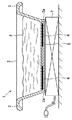
以下、図面に基づいて、本発明を実施するための最良の形態について説明する。図1は本発明の第1実施形態である電磁調理器用鍋を示す垂直断面図であり、図2は図1に示す電磁調理器用鍋の底面図である。 Hereinafter, the best mode for carrying out the present invention will be described with reference to the drawings. FIG. 1 is a vertical sectional view showing a pan for an electromagnetic cooker according to a first embodiment of the present invention, and FIG. 2 is a bottom view of the pan for an electromagnetic cooker shown in FIG.
図1,図2に示すように、本実施形態の電磁調理器用鍋1において、一対の取っ手3を有する鍋本体2は、二酸化ケイ素、酸化アルミニウム、酸化第二鉄、二酸化チタン、酸化カルシウム、酸化マグネシウム、酸化ナトリウム、酸化マグネシウム、酸化ナトリウム、酸化カリウムおよび酸化リチウムを含有する磁器製である。この鍋本体2は、強化磁器材料である石英、セリサイト、カオリナイト、アルミナなどを主原料として焼成されたものである。
As shown in FIG. 1 and FIG. 2, in the pan 1 for an electromagnetic cooking device of the present embodiment, the
鍋本体2の外底面には、図2に示すように、銀を含有する発熱層4が底面視状態でドーナツ状に形成され、この発熱層4全体を被覆するように、酸化ケイ素、酸化ホウ素、酸化ナトリウム、酸化カリウムを含有する保護層5が形成されている。発熱層4の内周縁4aより内側の領域および外周縁4bと高台2aとの間の領域には発熱層4が無く、鍋本体2の外底面を直接、保護層5が被覆している。
As shown in FIG. 2, a
また、底面視状態でドーナツ状をした発熱層4には、発熱層4の存在しない円形の非発熱部6が斑点状に多数配置されている。これらの非発熱部6においては、鍋本体2の外底面を直接、保護層5が被覆している。なお、発熱層4は緻密な性状であるため、図2では全面黒色で表示すべきであるが、図面表示の都合上(全面黒色にすると非発熱部6を示す引き出し線が発熱層4と一体化して見えなくなるため)、発熱層4を細かな点の分布により表示している。
In addition, in the heat generating
図1に示すように、電磁調理器用鍋1を電磁調理器7の所定位置に載置し、電源をONすると、電磁調理器7から発生する交番磁界によって電磁調理器用鍋1の外底面の発熱層4に渦電流が生じ、このときの電気抵抗発熱によって発熱層4が発熱するため、この熱が鍋本体2に伝達され、内部に収容されている食材Fを加熱調理することができる。
As shown in FIG. 1, when the electromagnetic cooker pan 1 is placed at a predetermined position of the electromagnetic cooker 7 and the power is turned on, heat is generated on the outer bottom surface of the electromagnetic cooker pan 1 by an alternating magnetic field generated from the electromagnetic cooker 7. Since the eddy current is generated in the
このように、鍋本体2が非導電性の磁器材料で形成されていても電磁調理器7を用いた加熱調理が可能であるため、電磁調理器用鍋1特有の機能である、遠赤外線による加熱機能、保温機能を発揮させることができるため、便利である。また、発熱層4は銀を含有しているため、誘導加熱効率が高く、発熱量も高い。さらに、保護層5は、酸化ケイ素、酸化ホウ素、酸化ナトリウム、酸化カリウムなどの釉薬成分を含有しているため、鍋本体2および発熱層4との密着性が良好であり、洗剤や塩分などの化学薬品で腐食されず、耐久性に優れている。
Thus, even if the
また、発熱層4は、鍋本体2の外底面全体に配置せず、ドーナツ状に配置しているため、発熱層4の構成材料である高価な銀の使用量を減らすことができるほか、渦電流による発熱が外底面の中心付近の一カ所へ集中することを防ぐことができる。また、渦電流が均一化されることによって発熱層4全体が均等に発熱するため、クラック、亀裂の発生を防止することができる。そのほか、非発熱部6のミクロン単位の凹凸に対応できるという効果もある。
Moreover, since the
さらに、発熱層4を形成した領域には、発熱層4の存在しない多数の非発熱部6を斑点状に配置しているため、電磁調理器7を用いた加熱調理を繰り返した場合の、鍋本体2と発熱層4の熱膨張係数の違いに起因する収縮量の違いをこれらの非発熱部6が緩和することができる。このため、加熱調理を繰り返しても発熱層4にクラックや亀裂が生じたり、剥離したりすることがなく、耐久性に優れている。また、万一、発熱層4にクラックや亀裂が発生した場合でも、これらのクラックや亀裂の進行は非発熱部6で止められるため、発熱量の低下を招くようなクラックや亀裂に発展することがない。
Furthermore, in the region where the
なお、発熱層4を形成する方法については特に限定するものではないが、例えば、スクリーン印刷法あるいはパッド印刷法などが好適である。このような印刷法で発熱層4を形成した場合、発熱層4全体に多数の斑点状の非発熱部6を配置する構成としたことにより、発熱層4の膜厚の均一性が高まるという効果も得られる。
The method for forming the
また、本実施形態では、図2に示すように、非発熱部6を、複数の同心円上に並ぶように配置しているため、渦電流が一カ所へ集中することを防ぐことができ、渦電流の均一化により発熱状態も均一化され、亀裂やクラックの発生を防止することができる。
In the present embodiment, as shown in FIG. 2, the
さらに、非発熱部6の形状を円形斑点としたことにより、非発熱部6の外縁を形成する発熱層4は滑らかな円形となるため、この非発熱部6自体が発熱層4の亀裂やクラックの発生源となることを回避することができる。また、非発熱部6を包囲する発熱層4の熱膨張を緩和することができるため、亀裂やクラックの発生を防止する上で有効である。
Furthermore, since the
なお、電磁調理器用鍋1においては、発熱層4および非発熱部6の配置形状を明示するため保護層5を無色透明としているが、これに限定するものではないので、例えば、保護層5に色を付けたり、保護層5の色を発熱層4の色と同じにしたりすることもできる。保護層5を発熱層4と同色にすれば、電磁調理器用鍋1の外底面部分において、発熱層4および非発熱部6の配置形状が目立たなくなるため、外観性が向上するという効果も得られる。
In addition, in the electromagnetic cooker pan 1, the
ここで、図3を参照して、電磁調理器用鍋1を構成する発熱層4および保護層5に関するその他の実施の形態について説明する。図3は、図1に示す電磁調理器用鍋1を構成する発熱層および保護層に関するその他の実施の形態を示す垂直断面図である。
Here, with reference to FIG. 3, other embodiment regarding the
図3(a)に示す電磁調理器用鍋8においては、鍋本体9の外底面および内底面の両方に発熱層4および発熱層4を被覆する保護層5を形成し、図3(b)に示す電磁調理器用鍋10においては、鍋本体11の内底面のみに発熱層4およびこれを被覆する保護層5を形成している。発熱層4および保護層5の形状および機能については、図1,図2に示す電磁調理器用鍋1の場合と同様である。
In the
図3(a)に示す電磁調理器用鍋8では鍋本体9の外底面および内底面の両方に発熱層4および保護層5を形成しているため、発熱量が多く、食材Fを素早く加熱調理することができる。また、外底面および内底面の両方に発熱層4があるので、それぞれの発熱層4を薄くしても十分な発熱量を得ることができ、発熱層4を薄膜化することによってクラックや亀裂を防ぐことができるという効果もある。
In the
一方、図3(b)に示す電磁調理器用鍋10では鍋本体9の内底面のみに発熱層4および保護層5を形成しているため、発熱層4が食材に近い位置に存在することとなる結果、食材Fを早く加熱することができるという効果が得られる。なお、この電磁調理器用鍋10および前述した電磁調理器用鍋8に関するその他の機能、効果については、前述した電磁調理器用鍋1と同様である。
On the other hand, in the
次に、図4を参照して、本発明の第2実施形態である電磁調理器用鍋20について説明する。図4は本発明の第2実施形態である電磁調理器用鍋を示す底面図である。なお、電磁調理器用鍋20の構成部分において、前述した電磁調理器用鍋1の構成部分と同じ機能、効果を発揮する部分については図4において図1,図2と同じ符号を付して説明を省略する。
Next, with reference to FIG. 4, the
本実施形態の電磁調理器用鍋20においては、鍋本体21の外底面に径の異なるドーナツ状の発熱層24a,24b,24cを同心円状に配置し、これらの発熱層24a,24b,24cの間に、2つの非発熱部26a,26bを同心円状に配置し、これらの発熱層24a,24b,24cおよび非発熱部26a,26bを被覆するように保護層25が形成されている。また、発熱層24aの内周縁24dより内側の領域および発熱層24cの外周縁24eと高台21aとの間の領域では、鍋本体21を直接保護層25が被覆している。
In the
なお、発熱層24a,24b,24cは緻密な性状であるため、図4ではこれらを全面黒色で表示すべきであるが、図面表示の都合上(全面黒色にすると非発熱部26a,26bを示す引き出し線などが発熱層24b,24cと一体化して見えなくなるため)、発熱層24a,24bを細かな点の分布により表示している。
Since the
電磁調理器用鍋20においては、発熱層24a,24b,24cの間に、2つの非発熱部26a,26bが同心円状に配置されているため、鍋本体21の底部の半径方向に進行するクラックや亀裂を効果的に防止することができる。また、斑点状の非発熱部を設けた前述の電磁調理器用鍋1と比べた場合、クラックや亀裂がどの場所で発生しても、その半径方向の進行を最小限に食い止めることができる、という効果が得られる。さらに、発熱層24a,24b,24cがそれぞれ独立しているので、これらの個数を増減させることによって、鍋本体21の底部の直径の大小に容易に対応することができる、という製造工程上のメリットもある。
In the
なお、本実施形態では、発熱層24a,24b,24cおよび非発熱部26a,26bを鍋本体21の外底面のみに配置しているが、これに限定するものではなく、図3で示したように、鍋本体21の外底面および内底面の両方に配置したり、内底面のみに配置したりすることも可能であり、それぞれ前述したような機能、効果を発揮する。
In the present embodiment, the
本発明に係る電磁調理器用鍋は、一般に使用されている電磁調理器で加熱調理を行う場合に広く利用することができるほか、ガスコンロ、電子レンジ、オーブン、ハロゲンヒータなどの加熱調理器にも利用することができ、焼く、煮る、炊く、蒸す、湯煎などの様々な加熱調理を行うことができる。 The pan for an electromagnetic cooker according to the present invention can be widely used when cooking with a generally used electromagnetic cooker, and also used for a cooker such as a gas stove, microwave oven, oven, halogen heater, etc. Can be cooked, boiled, boiled, cooked, steamed, hot water roasted, etc.
1,8,10,20 電磁調理器用鍋
2,9,11,21 鍋本体
2a,9a,11a,21a 高台
3 取っ手
4,24a,24b,24c 発熱層
4a,24d 内周縁
4b,24e 外周縁
5,25 保護層
6,26a,26b 非発熱部
7 電磁調理器
F 食材
1,8,10,20
Claims (5)
前記発熱層が形成された鍋本体の内底面および外底面の一部に、当該発熱層が存在しない非発熱部を設けたことを特徴とする電磁調理器用鍋。 Porcelain pan body containing silicon dioxide, aluminum oxide, ferric oxide, titanium dioxide, calcium oxide, magnesium oxide, sodium oxide, magnesium oxide, sodium oxide, potassium oxide and lithium oxide, and at least one of platinum and silver a heat generating layer formed on both the inner bottom and outer bottom surface of the pan body containing silicon oxide, boron oxide, sodium oxide, is formed so as to cover the heat generating layer contains any of potassium oxide A pan for an electromagnetic cooker with a protective layer,
A pan for an electromagnetic cooker, characterized in that a non-heat generating portion in which the heat generating layer does not exist is provided on a part of the inner bottom surface and the outer bottom surface of the pan body on which the heat generating layer is formed.
Priority Applications (1)
| Application Number | Priority Date | Filing Date | Title |
|---|---|---|---|
| JP2003287009A JP4159426B2 (en) | 2003-08-05 | 2003-08-05 | Induction cooker pan |
Applications Claiming Priority (1)
| Application Number | Priority Date | Filing Date | Title |
|---|---|---|---|
| JP2003287009A JP4159426B2 (en) | 2003-08-05 | 2003-08-05 | Induction cooker pan |
Publications (2)
| Publication Number | Publication Date |
|---|---|
| JP2005052425A JP2005052425A (en) | 2005-03-03 |
| JP4159426B2 true JP4159426B2 (en) | 2008-10-01 |
Family
ID=34366145
Family Applications (1)
| Application Number | Title | Priority Date | Filing Date |
|---|---|---|---|
| JP2003287009A Expired - Fee Related JP4159426B2 (en) | 2003-08-05 | 2003-08-05 | Induction cooker pan |
Country Status (1)
| Country | Link |
|---|---|
| JP (1) | JP4159426B2 (en) |
Families Citing this family (8)
| Publication number | Priority date | Publication date | Assignee | Title |
|---|---|---|---|---|
| KR100721588B1 (en) * | 2005-12-23 | 2007-05-23 | 쿠쿠전자주식회사 | Oven for induction heating rice cooker |
| JP4867435B2 (en) * | 2006-04-04 | 2012-02-01 | 東洋製罐株式会社 | Induction heating auxiliary tool, induction heating heating element, and induction heating container |
| JP5050657B2 (en) * | 2007-05-29 | 2012-10-17 | パナソニック株式会社 | Non-conducting pan for induction heating and induction heating cooker using the same |
| JP6127593B2 (en) * | 2012-09-28 | 2017-05-17 | 東洋製罐グループホールディングス株式会社 | Induction heating vessel |
| US10464164B2 (en) * | 2017-11-17 | 2019-11-05 | Orgo-Thermit Inc. | Rail welding crucible and cap with an oxygen/propane gas rail-preheating burner ignited reaction starter mix |
| WO2022158616A1 (en) * | 2021-01-22 | 2022-07-28 | 황재현 | Frying pan |
| CN113276283B (en) * | 2021-06-04 | 2022-10-04 | 西藏雍仲皂石研发有限公司 | Aluminum-clad stone processing technology |
| CN115251696B (en) * | 2022-08-03 | 2023-06-27 | 浙江三禾厨具有限公司 | Preparation method for pan oxidation |
-
2003
- 2003-08-05 JP JP2003287009A patent/JP4159426B2/en not_active Expired - Fee Related
Also Published As
| Publication number | Publication date |
|---|---|
| JP2005052425A (en) | 2005-03-03 |
Similar Documents
| Publication | Publication Date | Title |
|---|---|---|
| US9833101B2 (en) | Pan and method for making | |
| JPH10192140A (en) | Contact type heat conduction cooking system having electric heating plate | |
| JP4159426B2 (en) | Induction cooker pan | |
| JP4210281B2 (en) | Electromagnetic induction heating rice cooker inner pot | |
| JP4984941B2 (en) | Electric rice cooker | |
| JP2004192980A (en) | Plate for induction heating cooker | |
| CA2760568C (en) | Induction cookware for keeping food warm | |
| JP2005237646A (en) | Earthen pot for electromagnetic cooker | |
| JP4349943B2 (en) | rice cooker | |
| JP2012110636A (en) | Cooking container for induction-heating cooker | |
| WO2009015535A1 (en) | Electric heating container and electric heating method | |
| JP2003250698A (en) | Electromagnetic cooking container | |
| JP2007175095A (en) | Inner pot for gas rice cooker | |
| JP2009082356A (en) | Cooking pot | |
| JP2007130311A (en) | Nonmetallic container for electromagnetic induction cooker | |
| JP5125019B2 (en) | Inner container for induction heating rice cookers | |
| JPH05251169A (en) | Heating body and container for electromagnetic cooking | |
| JPH0234436B2 (en) | ||
| KR20090030952A (en) | Cooking pot | |
| JP2006167157A (en) | Pot for ih cooking heater | |
| JP2014136023A (en) | Earthen pot for ih cooker | |
| JPH09140593A (en) | Cooking utensil | |
| KR101971345B1 (en) | Induction cooker | |
| JP5918276B2 (en) | kitchenware | |
| KR20180013586A (en) | Pad for ceramics fan |
Legal Events
| Date | Code | Title | Description |
|---|---|---|---|
| A621 | Written request for application examination |
Free format text: JAPANESE INTERMEDIATE CODE: A621 Effective date: 20060804 |
|
| A977 | Report on retrieval |
Free format text: JAPANESE INTERMEDIATE CODE: A971007 Effective date: 20071116 |
|
| A131 | Notification of reasons for refusal |
Free format text: JAPANESE INTERMEDIATE CODE: A131 Effective date: 20071120 |
|
| A521 | Written amendment |
Free format text: JAPANESE INTERMEDIATE CODE: A523 Effective date: 20080121 |
|
| TRDD | Decision of grant or rejection written | ||
| A01 | Written decision to grant a patent or to grant a registration (utility model) |
Free format text: JAPANESE INTERMEDIATE CODE: A01 Effective date: 20080624 |
|
| A01 | Written decision to grant a patent or to grant a registration (utility model) |
Free format text: JAPANESE INTERMEDIATE CODE: A01 |
|
| A61 | First payment of annual fees (during grant procedure) |
Free format text: JAPANESE INTERMEDIATE CODE: A61 Effective date: 20080715 |
|
| R150 | Certificate of patent or registration of utility model |
Free format text: JAPANESE INTERMEDIATE CODE: R150 |
|
| FPAY | Renewal fee payment (event date is renewal date of database) |
Free format text: PAYMENT UNTIL: 20110725 Year of fee payment: 3 |
|
| FPAY | Renewal fee payment (event date is renewal date of database) |
Free format text: PAYMENT UNTIL: 20120725 Year of fee payment: 4 |
|
| FPAY | Renewal fee payment (event date is renewal date of database) |
Free format text: PAYMENT UNTIL: 20130725 Year of fee payment: 5 |
|
| R250 | Receipt of annual fees |
Free format text: JAPANESE INTERMEDIATE CODE: R250 |
|
| R250 | Receipt of annual fees |
Free format text: JAPANESE INTERMEDIATE CODE: R250 |
|
| R250 | Receipt of annual fees |
Free format text: JAPANESE INTERMEDIATE CODE: R250 |
|
| R250 | Receipt of annual fees |
Free format text: JAPANESE INTERMEDIATE CODE: R250 |
|
| LAPS | Cancellation because of no payment of annual fees |