EP2901545B1 - Soft switching synchronous quasi resonant converter - Google Patents
Soft switching synchronous quasi resonant converter Download PDFInfo
- Publication number
- EP2901545B1 EP2901545B1 EP13773576.7A EP13773576A EP2901545B1 EP 2901545 B1 EP2901545 B1 EP 2901545B1 EP 13773576 A EP13773576 A EP 13773576A EP 2901545 B1 EP2901545 B1 EP 2901545B1
- Authority
- EP
- European Patent Office
- Prior art keywords
- mosfet switch
- primary
- switch
- current
- coupled
- Prior art date
- Legal status (The legal status is an assumption and is not a legal conclusion. Google has not performed a legal analysis and makes no representation as to the accuracy of the status listed.)
- Active
Links
Images


Classifications
-
- H—ELECTRICITY
- H05—ELECTRIC TECHNIQUES NOT OTHERWISE PROVIDED FOR
- H05B—ELECTRIC HEATING; ELECTRIC LIGHT SOURCES NOT OTHERWISE PROVIDED FOR; CIRCUIT ARRANGEMENTS FOR ELECTRIC LIGHT SOURCES, IN GENERAL
- H05B45/00—Circuit arrangements for operating light-emitting diodes [LED]
- H05B45/30—Driver circuits
- H05B45/37—Converter circuits
- H05B45/3725—Switched mode power supply [SMPS]
- H05B45/385—Switched mode power supply [SMPS] using flyback topology
-
- H—ELECTRICITY
- H02—GENERATION; CONVERSION OR DISTRIBUTION OF ELECTRIC POWER
- H02M—APPARATUS FOR CONVERSION BETWEEN AC AND AC, BETWEEN AC AND DC, OR BETWEEN DC AND DC, AND FOR USE WITH MAINS OR SIMILAR POWER SUPPLY SYSTEMS; CONVERSION OF DC OR AC INPUT POWER INTO SURGE OUTPUT POWER; CONTROL OR REGULATION THEREOF
- H02M3/00—Conversion of DC power input into DC power output
- H02M3/22—Conversion of DC power input into DC power output with intermediate conversion into AC
- H02M3/24—Conversion of DC power input into DC power output with intermediate conversion into AC by static converters
- H02M3/28—Conversion of DC power input into DC power output with intermediate conversion into AC by static converters using discharge tubes with control electrode or semiconductor devices with control electrode to produce the intermediate AC
- H02M3/325—Conversion of DC power input into DC power output with intermediate conversion into AC by static converters using discharge tubes with control electrode or semiconductor devices with control electrode to produce the intermediate AC using devices of a triode or a transistor type requiring continuous application of a control signal
- H02M3/335—Conversion of DC power input into DC power output with intermediate conversion into AC by static converters using discharge tubes with control electrode or semiconductor devices with control electrode to produce the intermediate AC using devices of a triode or a transistor type requiring continuous application of a control signal using semiconductor devices only
- H02M3/3353—Conversion of DC power input into DC power output with intermediate conversion into AC by static converters using discharge tubes with control electrode or semiconductor devices with control electrode to produce the intermediate AC using devices of a triode or a transistor type requiring continuous application of a control signal using semiconductor devices only having at least two simultaneously operating switches on the input side, e.g. "double forward" or "double (switched) flyback" converter
-
- H—ELECTRICITY
- H02—GENERATION; CONVERSION OR DISTRIBUTION OF ELECTRIC POWER
- H02M—APPARATUS FOR CONVERSION BETWEEN AC AND AC, BETWEEN AC AND DC, OR BETWEEN DC AND DC, AND FOR USE WITH MAINS OR SIMILAR POWER SUPPLY SYSTEMS; CONVERSION OF DC OR AC INPUT POWER INTO SURGE OUTPUT POWER; CONTROL OR REGULATION THEREOF
- H02M3/00—Conversion of DC power input into DC power output
- H02M3/22—Conversion of DC power input into DC power output with intermediate conversion into AC
- H02M3/24—Conversion of DC power input into DC power output with intermediate conversion into AC by static converters
- H02M3/28—Conversion of DC power input into DC power output with intermediate conversion into AC by static converters using discharge tubes with control electrode or semiconductor devices with control electrode to produce the intermediate AC
- H02M3/325—Conversion of DC power input into DC power output with intermediate conversion into AC by static converters using discharge tubes with control electrode or semiconductor devices with control electrode to produce the intermediate AC using devices of a triode or a transistor type requiring continuous application of a control signal
- H02M3/335—Conversion of DC power input into DC power output with intermediate conversion into AC by static converters using discharge tubes with control electrode or semiconductor devices with control electrode to produce the intermediate AC using devices of a triode or a transistor type requiring continuous application of a control signal using semiconductor devices only
- H02M3/33569—Conversion of DC power input into DC power output with intermediate conversion into AC by static converters using discharge tubes with control electrode or semiconductor devices with control electrode to produce the intermediate AC using devices of a triode or a transistor type requiring continuous application of a control signal using semiconductor devices only having several active switching elements
- H02M3/33576—Conversion of DC power input into DC power output with intermediate conversion into AC by static converters using discharge tubes with control electrode or semiconductor devices with control electrode to produce the intermediate AC using devices of a triode or a transistor type requiring continuous application of a control signal using semiconductor devices only having several active switching elements having at least one active switching element at the secondary side of an isolation transformer
- H02M3/33592—Conversion of DC power input into DC power output with intermediate conversion into AC by static converters using discharge tubes with control electrode or semiconductor devices with control electrode to produce the intermediate AC using devices of a triode or a transistor type requiring continuous application of a control signal using semiconductor devices only having several active switching elements having at least one active switching element at the secondary side of an isolation transformer having a synchronous rectifier circuit or a synchronous freewheeling circuit at the secondary side of an isolation transformer
-
- H—ELECTRICITY
- H05—ELECTRIC TECHNIQUES NOT OTHERWISE PROVIDED FOR
- H05B—ELECTRIC HEATING; ELECTRIC LIGHT SOURCES NOT OTHERWISE PROVIDED FOR; CIRCUIT ARRANGEMENTS FOR ELECTRIC LIGHT SOURCES, IN GENERAL
- H05B45/00—Circuit arrangements for operating light-emitting diodes [LED]
- H05B45/30—Driver circuits
- H05B45/37—Converter circuits
- H05B45/3725—Switched mode power supply [SMPS]
- H05B45/382—Switched mode power supply [SMPS] with galvanic isolation between input and output
-
- H—ELECTRICITY
- H02—GENERATION; CONVERSION OR DISTRIBUTION OF ELECTRIC POWER
- H02M—APPARATUS FOR CONVERSION BETWEEN AC AND AC, BETWEEN AC AND DC, OR BETWEEN DC AND DC, AND FOR USE WITH MAINS OR SIMILAR POWER SUPPLY SYSTEMS; CONVERSION OF DC OR AC INPUT POWER INTO SURGE OUTPUT POWER; CONTROL OR REGULATION THEREOF
- H02M1/00—Details of apparatus for conversion
- H02M1/0048—Circuits or arrangements for reducing losses
- H02M1/0054—Transistor switching losses
- H02M1/0058—Transistor switching losses by employing soft switching techniques, i.e. commutation of transistors when applied voltage is zero or when current flow is zero
-
- Y—GENERAL TAGGING OF NEW TECHNOLOGICAL DEVELOPMENTS; GENERAL TAGGING OF CROSS-SECTIONAL TECHNOLOGIES SPANNING OVER SEVERAL SECTIONS OF THE IPC; TECHNICAL SUBJECTS COVERED BY FORMER USPC CROSS-REFERENCE ART COLLECTIONS [XRACs] AND DIGESTS
- Y02—TECHNOLOGIES OR APPLICATIONS FOR MITIGATION OR ADAPTATION AGAINST CLIMATE CHANGE
- Y02B—CLIMATE CHANGE MITIGATION TECHNOLOGIES RELATED TO BUILDINGS, e.g. HOUSING, HOUSE APPLIANCES OR RELATED END-USER APPLICATIONS
- Y02B20/00—Energy efficient lighting technologies, e.g. halogen lamps or gas discharge lamps
- Y02B20/30—Semiconductor lamps, e.g. solid state lamps [SSL] light emitting diodes [LED] or organic LED [OLED]
-
- Y—GENERAL TAGGING OF NEW TECHNOLOGICAL DEVELOPMENTS; GENERAL TAGGING OF CROSS-SECTIONAL TECHNOLOGIES SPANNING OVER SEVERAL SECTIONS OF THE IPC; TECHNICAL SUBJECTS COVERED BY FORMER USPC CROSS-REFERENCE ART COLLECTIONS [XRACs] AND DIGESTS
- Y02—TECHNOLOGIES OR APPLICATIONS FOR MITIGATION OR ADAPTATION AGAINST CLIMATE CHANGE
- Y02B—CLIMATE CHANGE MITIGATION TECHNOLOGIES RELATED TO BUILDINGS, e.g. HOUSING, HOUSE APPLIANCES OR RELATED END-USER APPLICATIONS
- Y02B70/00—Technologies for an efficient end-user side electric power management and consumption
- Y02B70/10—Technologies improving the efficiency by using switched-mode power supplies [SMPS], i.e. efficient power electronics conversion e.g. power factor correction or reduction of losses in power supplies or efficient standby modes
Definitions
- the present disclosure relates to switched mode power supplies, in particular to drive a load, and more particular to driving and dimming of light emitting diodes (LEDs).
- LEDs light emitting diodes
- a switch mode power supply is used to provide a constant voltage to a load via a low pass filter and using a semiconductor device such as a power transistor (e.g., a MOSFET) as a switch.
- a semiconductor device such as a power transistor (e.g., a MOSFET) as a switch.
- the semiconductor switches used to implement switch mode power supplies are continuously switched on and off at high frequencies (50 kHz to several MHz), to transfer electrical energy from the input to the output through the passive components.
- EMI electromagnetic interference
- a switching circuit does comprise a transformer having a primary and a secondary side; a first MOSFET switch coupled with the primary side; a primary current sensing device; a second MOSFET switch coupled with the secondary side; a secondary current sensing device; and a control circuit for driving the first and second MOSFET switches, wherein first and second switch are complementarily driven and wherein switching of the first and second MOSFET switches is controlled by the primary and secondary current sensing devices.
- the primary and secondary current sensing devices do each comprise a shunt resistor coupled between a ground and the respective first or second MOSFET switch.
- the switching circuit may further comprise a current sensing amplifier coupled to the secondary current sensing device.
- the switching circuit does further comprise a comparator receiving first and second current sensing signals and having an output coupled with the control circuit.
- the control circuit does comprise a pulse width modulator.
- a power supply circuit includes a control circuit; and a quasi-resonant flyback circuit including: a primary circuit controlled by a first transistor switch and including a first current sensing device; a secondary circuit controlled by a second transistor switch and including a second current sensing device; and a transformer having a primary and a secondary side; wherein the control circuit is configured to drive said first transistor switch and said second transistor switch, wherein said first transistor switch and said second transistor switch are complementarily driven and wherein switching of said first transistor switch and said second transistor switch is controlled via the first and second current sensing devices.
- the primary and secondary current sensing devices each comprise a shunt resistor coupled between a ground and the respective first or second transistor switch.
- the circuit further includes a current sensing amplifier coupled to the second current sensing device.
- the circuit includes a comparator receiving first and second current sensing signals and having an output coupled with the control circuit.
- the control circuit includes a pulse width modulator.
- a method includes charging an output capacitor through a flyback transformer with a primary switch, the flyback transformer and the primary switch coupled to a power source; discharging the output capacitor through the flyback transformer with a secondary switch, the flyback transformer and the secondary switch being coupled to the output capacitor; sensing a current of the primary switch; sensing a current of the secondary switch; and driving said primary switch and said secondary switch, wherein said primary switch and said secondary switch are complementarily driven and wherein switching of said primary switch and said secondary switch is controlled responsive to sensing the current of the primary switch and the secondary switch.
- the sensing of the current of the primary switch and the sensing of the current of the secondary switch is accomplished using shunt resistors coupled between a ground and the respective primary or secondary switch.
- the method further includes comprising amplifying a current of the secondary switch.
- driving said primary and secondary switch includes driving said primary and secondary switch suing a pulse width modulator.
- a device for controlling a load has synchronous capability for voltage positioning. Zero voltage switching is provided by controlling the reverse current using the device, thereby increasing device efficiency and reducing EMI.
- a switched mode power supply (SMPS) architecture may use a synchronous SMPS design to reposition voltage for dimming LED's.
- the synchronous switch according to such an architecture is used to load the magnetic device and use the reverse energy to soft switch the MOSFET. Soft switching the MOSFET significantly increases efficiency and reduces EMI.
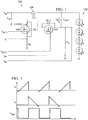
- FIG. 1 Shown in FIG. 1 is a SMPS 100 driving a load 102 which may be embodied as a plurality of light emitting diodes (LED).
- the circuit 100 includes a pair of MOSFET switches SW1, SW2, respectively, flyback transformer 104, output capacitor Cout, and sense resistors Rp, Rs for sensing the current at the outputs of SW1, SW2, respectively.
- the primary switch SW1 is turned on after detecting the ringing waveform on the drain of SW1.
- the ring on SW1 is caused by the demagnetization of the flyback transformer 104 due to the lack of magnetizing current clamping the secondary winding to Vout through the body diode of SW2 (BD_2).
- SW2 provides a path for current to flow in the "normal" direction charging C OUT .
- SW2 provides a path for C OUT to drive the core in the reverse direction (reverse current).
- This energy stored can be used to reset or clamp the SW2 drain voltage to 0 V or a diode drop below Ground by operating the flyback transformer 104 in the reverse direction. This forces soft switching of the SW1 switch, eliminating switching losses and significantly reducing the EMI caused by high dv/dt due to MOSFET's switching voltage (hard switching).
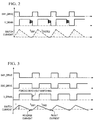
- FIG. 2 illustrates exemplary waveforms for the circuit of FIG. 1 .
- SW1_Drive (representing Vext of FIG. 1 ) drives SW1 to turn on after the ringing on V_Drain is detected.
- I SW1 corresponds to I P or primary current ( FIG. 1 ).
- Diode 2 current, I DIODE2 corresponds to I SN or secondary current ( FIG. 1 ).
- the circuit of FIG. 1 thus forms a quasi-resonant flyback converter.
- embodiments implement a synchronous quasi-resonant circuit.
- high voltage topologies do not benefit from such synchronous operation. Forcing reverse current and turning SW2 off at the right time is not trivial, requires respective current sense and fast, low offset comparator(s).
- a synchronous dimming method is used for zero volt switching.
- the synchronous switch is added to position the output voltage for LED dimming.
- the method is further used to generate a "square" wave current driver for multiple LED strings.
- the synchronous switch is used to reverse energy from stored output capacitor.
- the stored energy is used to discharge the capacitance on the primary FET. This results in zero voltage switching, as shown in FIG. 3 .
- variable frequency converters with bi-directional or synchronous capability.
- High input voltage, low to medium power applications receive the most benefit.
- Many synchronous topologies can benefit from this concept (fly back, boost, SEPIC, Cuk, etc.).
- FIG. 4 A more detailed circuit of the embodiment shown in FIG. 1 , in particular with respect to the current sensing is shown in FIG. 4 .
- current sensing for the primary (I P ) and secondary circuit (I S ) are compared and a resulting control signal is fed to a pulse width modulator PWM 404.
- the PWM logic then provides the V SW1 and V SW2 control drive voltages.
- the current Ip from Qp is provided to comparator 410.
- Current I S from Qs is provided to amplifier filter circuitry 402 including amplifiers 406 and 408
- Amplifier circuit 406 is used to gain the current sense signal since low value resistors are used to keep efficiency high.
- Amplifier 408 is used to regulate the LED current using a traditional error amplifier, V REF and feedback signal from amplifier 406.
- a desat comparator 405 may provide a QRS output to the PWM 404 for detecting zero transformer energy (i.e., used to reverse current for output voltage positioning/zero volt switching).
- FIG. 5 illustrates current flow according to the embodiment of FIG. 4 .
- the V SW1 drive controls the SW1 and switchover from Ip to Is.
- the PDRV (primary transistor drive signal)( FIG. 6 ) is used to store energy in transformer 104 while switch Qp is turned “ON". During this time primary current flows through sense resistor Rp. Once the desired primary peak current is reached PDRV turns off Qp and SDRV (secondary transistor drive signal)( FIG. 6 ) turns "ON" Qs.
- transformer 104 provides current to the LED's and replenishes the charge into COUT. Zero transformer energy is detected when the desaturation comparator 405 ( FIG. 4 ) inputs desat+ and desat- have a 0 V differential.
- Additional offset or delay can be added to "reverse" current into transformer 104 allowing the current to reverse through the synchronous switch.
- This stored energy is used to force current flow through the body diode of Qp after Qs turn off resulting in 0V across switch Qp.
- the PDRV signal turns Qp on after the switch drain source voltage has reached 0V eliminating switching losses and reducing EMI.
- the cycle repeats itself when Qp turns on until the desired peak current is reached.
- the desired peak current is reached when the comp 410 non-inverting current ramp signal exceeds the inverting comp 410 input. This is the regulation loop for LED current, independent of the quasi-resonant comparator operation.
- FIG. 6 illustrates an exemplary implementation of a flyback quasi resonant circuit. As shown, the function of the circuitry 402 and the PWM logic may be implemented in an integrated circuit.
- the various embodiments provide for the following benefits of quasi resonant synchronous zero volt switching operation: Switching losses are eliminated, wherein largest impact is on AC-DC or very high voltage input designs. EMI is significantly reduced, because even zero current switching topologies introduce some noise.
- the terms “comprises,” “comprising,” “includes,” “including,” “has,” “having,” or any other variation thereof, are intended to cover a non-exclusive inclusion.
- a process, product, article, or apparatus that comprises a list of elements is not necessarily limited only those elements but may include other elements not expressly listed or inherent to such process, process, article, or apparatus.
Landscapes
- Engineering & Computer Science (AREA)
- Power Engineering (AREA)
- Dc-Dc Converters (AREA)
- Led Devices (AREA)
Applications Claiming Priority (3)
| Application Number | Priority Date | Filing Date | Title |
|---|---|---|---|
| US201261707506P | 2012-09-28 | 2012-09-28 | |
| US14/038,199 US9882497B2 (en) | 2012-09-28 | 2013-09-26 | Soft switching synchronous quasi resonant converter |
| PCT/US2013/062193 WO2014052761A2 (en) | 2012-09-28 | 2013-09-27 | Soft switching synchronous quasi resonant converter |
Publications (2)
| Publication Number | Publication Date |
|---|---|
| EP2901545A2 EP2901545A2 (en) | 2015-08-05 |
| EP2901545B1 true EP2901545B1 (en) | 2021-10-27 |
Family
ID=50385027
Family Applications (1)
| Application Number | Title | Priority Date | Filing Date |
|---|---|---|---|
| EP13773576.7A Active EP2901545B1 (en) | 2012-09-28 | 2013-09-27 | Soft switching synchronous quasi resonant converter |
Country Status (7)
Families Citing this family (18)
| Publication number | Priority date | Publication date | Assignee | Title |
|---|---|---|---|---|
| US9660535B2 (en) * | 2011-11-11 | 2017-05-23 | Microchip Technology Incorporated | Method and system to dynamically position a switch mode power supply output voltage |
| US8995150B2 (en) * | 2012-12-05 | 2015-03-31 | Dialog Semiconductor Inc. | Primary side sense output current regulation |
| JP2018502545A (ja) * | 2015-01-05 | 2018-01-25 | フィリップス ライティング ホールディング ビー ヴィ | 深い減光のための電源 |
| US10116222B2 (en) * | 2015-02-06 | 2018-10-30 | Texas Instruments Incorporated | Soft switching flyback converter with primary control |
| JP6698157B2 (ja) | 2015-07-22 | 2020-05-27 | プレ−スイッチ インコーポレイテッドPRE−SWiTCH, INC. | 共振システムコントローラ及びサイクル毎の予測ソフトスイッチング |
| US9887634B2 (en) * | 2015-07-23 | 2018-02-06 | General Electric Company | Circuits and methods for synchronous rectification in resonant converters |
| US10069426B2 (en) * | 2016-03-12 | 2018-09-04 | Semiconductor Components Industries, Llc | Active clamp flyback converter |
| US9948192B2 (en) * | 2016-05-04 | 2018-04-17 | Toyota Motor Engineering & Manufacturing North America, Inc. | Quasi-resonant operation of a power conversion circuit including switches symmetrically arranged about a transformer |
| GB2558674B (en) * | 2017-01-10 | 2022-01-19 | Tridonic Gmbh & Co Kg | Apparatus for operating one or more lighting devices |
| CN108462392A (zh) * | 2017-02-17 | 2018-08-28 | 晶群科技有限公司 | 同步整流控制电路及其控制方法 |
| US10554134B2 (en) * | 2017-06-02 | 2020-02-04 | Power Integrations, Inc. | Idle ring detection for a multi-output power converter |
| CN108173434B (zh) * | 2018-01-15 | 2020-06-09 | 昂宝电子(上海)有限公司 | 开关电源电路 |
| US10574147B2 (en) * | 2018-01-16 | 2020-02-25 | Texas Instruments Incorporated | Methods and apparatus for zero voltage switching using flyback converters |
| DE102018203310A1 (de) * | 2018-03-06 | 2019-09-12 | Tridonic Gmbh & Co Kg | Synchronkonverter mit digitaler Laststromerfassung |
| DE102018114926B4 (de) * | 2018-06-21 | 2023-08-24 | Tridonic Gmbh & Co Kg | Synchrone Sperrwandlerschaltungen zum Betrieb einer Leuchtmittelstrecke, Leuchte mit einer synchronen Sperrwandlerschaltung, und Verfahren zum Betreiben einer synchronen Sperrwandlerschaltung |
| US11736026B2 (en) * | 2020-05-29 | 2023-08-22 | Dialog Semiconductor Inc. | Flyback converter with fast load transient detection |
| US11653432B1 (en) * | 2021-11-30 | 2023-05-16 | Texas Instruments Incorporated | Light-emitting diode (LED) driver system with slew-rate control |
| CN118661368A (zh) * | 2022-02-28 | 2024-09-17 | 松下电器株式会社 | 电力转换系统 |
Citations (1)
| Publication number | Priority date | Publication date | Assignee | Title |
|---|---|---|---|---|
| US20090322234A1 (en) * | 2008-06-30 | 2009-12-31 | Iwatt Inc. | Led driver with multiple feedback loops |
Family Cites Families (40)
| Publication number | Priority date | Publication date | Assignee | Title |
|---|---|---|---|---|
| JPH0530739A (ja) * | 1991-07-18 | 1993-02-05 | Shindengen Electric Mfg Co Ltd | スイツチング電源装置 |
| US5568016A (en) | 1994-10-18 | 1996-10-22 | Norand Corporation | Power supply for an electroluminescent panel or the like |
| JPH08251926A (ja) * | 1995-03-14 | 1996-09-27 | Tamura Seisakusho Co Ltd | インバータ回路 |
| US5757626A (en) * | 1996-06-21 | 1998-05-26 | Delta Electronics Inc. | Single-stage, single-switch, islolated power-supply technique with input-current shaping and fast output-voltage regulation |
| AU2002231254A1 (en) | 2000-11-11 | 2002-05-21 | Nmb (Usa), Inc. | Power converter |
| US6606257B2 (en) | 2001-11-05 | 2003-08-12 | Koninklijke Philips Electronics N.V. | Independent regulation of multiple outputs in a soft-switching multiple-output flyback converter |
| US6671189B2 (en) | 2001-11-09 | 2003-12-30 | Minebea Co., Ltd. | Power converter having primary and secondary side switches |
| AT413908B (de) | 2002-08-12 | 2006-07-15 | Siemens Ag Oesterreich | Schaltwandler |
| US6788555B2 (en) | 2002-09-26 | 2004-09-07 | Koninklijke Philips Electronics N.V. | Regulation of bi-directional flyback converter |
| JP2005033888A (ja) | 2003-07-10 | 2005-02-03 | Seiko Instruments Inc | スイッチング・レギュレータ制御回路 |
| DE10356514A1 (de) | 2003-12-03 | 2005-07-14 | Siemens Ag | Stromversorgungseinrichtung |
| US7446518B2 (en) | 2004-03-08 | 2008-11-04 | Semtech Corporation | Method and apparatus for enhancing voltage regulator transient response |
| US7256554B2 (en) * | 2004-03-15 | 2007-08-14 | Color Kinetics Incorporated | LED power control methods and apparatus |
| US20050257647A1 (en) | 2004-05-19 | 2005-11-24 | David Baker | Pneumatic ratchet with forward/reverse actuator |
| US6995991B1 (en) | 2004-07-20 | 2006-02-07 | System General Corp. | PWM controller for synchronous rectifier of flyback power converter |
| JP4667836B2 (ja) | 2004-11-26 | 2011-04-13 | 株式会社リコー | スイッチングレギュレータ及びスイッチングレギュレータの出力電圧切換方法 |
| KR100628716B1 (ko) | 2005-02-02 | 2006-09-28 | 삼성전자주식회사 | Led구동장치 |
| US7456618B2 (en) | 2005-10-31 | 2008-11-25 | Chil Semiconductor, Inc. | Digital controller for a voltage regulator module |
| KR100727354B1 (ko) | 2005-11-09 | 2007-06-13 | 주식회사 유양정보통신 | 발광 다이오드 정전류 펄스폭 변조 구동 회로 |
| GB2435406A (en) | 2006-02-28 | 2007-08-29 | Otter Controls Ltd | Indicating operating mode of liquid heating device |
| US20080018261A1 (en) | 2006-05-01 | 2008-01-24 | Kastner Mark A | LED power supply with options for dimming |
| US8283904B2 (en) | 2006-09-13 | 2012-10-09 | Cree, Inc. | Circuitry for supplying electrical power to loads |
| CN100579323C (zh) | 2006-09-29 | 2010-01-06 | 启萌科技有限公司 | 发光装置及其驱动方法 |
| KR101493263B1 (ko) | 2006-10-06 | 2015-02-16 | 코닌클리케 필립스 엔.브이. | 광 소자용 전력 공급 장치 및 광 소자에 전력을 공급하는 방법 |
| US7902771B2 (en) | 2006-11-21 | 2011-03-08 | Exclara, Inc. | Time division modulation with average current regulation for independent control of arrays of light emitting diodes |
| JP2008187813A (ja) | 2007-01-30 | 2008-08-14 | Fuji Electric Device Technology Co Ltd | スイッチング電源 |
| US7852017B1 (en) | 2007-03-12 | 2010-12-14 | Cirrus Logic, Inc. | Ballast for light emitting diode light sources |
| KR101285579B1 (ko) * | 2007-03-19 | 2013-07-15 | 세미컨덕터 콤포넨츠 인더스트리즈 엘엘씨 | 배터리 충전기와 전원 공급 제어기 및 그에 대한 방법 |
| JP5109795B2 (ja) | 2008-05-13 | 2012-12-26 | ミツミ電機株式会社 | 電圧検出回路およびスイッチング電源装置 |
| JP5349905B2 (ja) * | 2008-10-27 | 2013-11-20 | パナソニック株式会社 | 放電灯点灯装置、及びこれを用いた車両用前照灯点灯装置 |
| US8054655B2 (en) | 2008-11-03 | 2011-11-08 | Monolithie Power Systems, Inc. | Tail current control of isolated converter and apparatus thereof |
| US8564155B2 (en) | 2009-05-06 | 2013-10-22 | Polar Semiconductor, Inc. | Multiple output power supply |
| CN201700054U (zh) | 2009-06-02 | 2011-01-05 | 立锜科技股份有限公司 | 无残光的发光二极管控制电路 |
| US8305004B2 (en) * | 2009-06-09 | 2012-11-06 | Stmicroelectronics, Inc. | Apparatus and method for constant power offline LED driver |
| US8587967B2 (en) * | 2009-06-10 | 2013-11-19 | Texas Instruments Incorporated | System and method for indirect control of a converter output |
| KR20110026749A (ko) | 2009-09-08 | 2011-03-16 | 삼성전자주식회사 | 백라이트 장치 및 이를 포함한 디스플레이 장치 |
| CN102065600B (zh) | 2010-03-16 | 2014-06-25 | 成都芯源系统有限公司 | 一种led调光驱动系统 |
| CN101848577B (zh) | 2010-03-16 | 2014-02-12 | 成都芯源系统有限公司 | 一种led驱动系统及驱动方法 |
| US9173261B2 (en) | 2010-07-30 | 2015-10-27 | Wesley L. Mokry | Secondary-side alternating energy transfer control with inverted reference and LED-derived power supply |
| JP5783597B2 (ja) * | 2010-10-15 | 2015-09-24 | コーセル株式会社 | スイッチング電源装置 |
-
2013
- 2013-09-26 US US14/038,199 patent/US9882497B2/en active Active
- 2013-09-27 EP EP13773576.7A patent/EP2901545B1/en active Active
- 2013-09-27 JP JP2015534742A patent/JP6486274B2/ja active Active
- 2013-09-27 KR KR1020157011019A patent/KR20150063140A/ko not_active Ceased
- 2013-09-27 CN CN201380051181.4A patent/CN104685777B/zh active Active
- 2013-09-27 WO PCT/US2013/062193 patent/WO2014052761A2/en active Application Filing
- 2013-09-27 TW TW102135168A patent/TWI610529B/zh active
Patent Citations (1)
| Publication number | Priority date | Publication date | Assignee | Title |
|---|---|---|---|---|
| US20090322234A1 (en) * | 2008-06-30 | 2009-12-31 | Iwatt Inc. | Led driver with multiple feedback loops |
Also Published As
| Publication number | Publication date |
|---|---|
| CN104685777B (zh) | 2017-09-01 |
| EP2901545A2 (en) | 2015-08-05 |
| CN104685777A (zh) | 2015-06-03 |
| US9882497B2 (en) | 2018-01-30 |
| WO2014052761A3 (en) | 2014-07-17 |
| JP6486274B2 (ja) | 2019-03-20 |
| KR20150063140A (ko) | 2015-06-08 |
| TWI610529B (zh) | 2018-01-01 |
| US20140092646A1 (en) | 2014-04-03 |
| JP2015536127A (ja) | 2015-12-17 |
| TW201424238A (zh) | 2014-06-16 |
| WO2014052761A2 (en) | 2014-04-03 |
Similar Documents
| Publication | Publication Date | Title |
|---|---|---|
| EP2901545B1 (en) | Soft switching synchronous quasi resonant converter | |
| US10250152B2 (en) | Forced zero voltage switching flyback converter | |
| US9899931B1 (en) | Zero voltage switching flyback converter for primary switch turn-off transitions | |
| TWI796419B (zh) | 具有多模式啟動之開關模式電力控制器 | |
| US8836310B2 (en) | Switch-mode power supply controller and associated method | |
| US8508958B2 (en) | LLC controller with programmable fractional burst frequency | |
| US9479069B2 (en) | Flyback-based power conversion apparatus with high conversion efficiency and low cost mechanism | |
| US20180294653A1 (en) | System and method for wireless power transfer using a power converter with a bypass mode | |
| US9787204B2 (en) | Switching power supply device | |
| US9397579B2 (en) | Full-bridge switching DC/DC converters and controllers thereof | |
| US9504105B2 (en) | On-time control for switched mode power supplies | |
| US8817497B2 (en) | Switching power converter for reducing EMI from ring oscillation and its control method | |
| US9935547B2 (en) | System and method for a switched-mode power supply | |
| WO2013053020A1 (en) | Power control | |
| US9337738B2 (en) | Transformer-coupled gate-drive power regulator system | |
| CN107634651B (zh) | 开关电源 | |
| JP6218722B2 (ja) | スイッチング電源装置 | |
| US10784785B2 (en) | Monitoring SMPS power switch voltage via switch drain source capacitance | |
| EP2897269A1 (en) | DC/DC converters | |
| US12218602B2 (en) | Switch mode power converter with synchronous rectifier implementing adaptive gate voltage regulation for fast turn-off | |
| Patel et al. | A Simulation of AC-DC Converter Topology for 48V, 50A, vrla Battery Charger Using Phase Shifted Pulses | |
| KR20050059841A (ko) | 전원공급장치용 lc 필터 |
Legal Events
| Date | Code | Title | Description |
|---|---|---|---|
| PUAI | Public reference made under article 153(3) epc to a published international application that has entered the european phase |
Free format text: ORIGINAL CODE: 0009012 |
|
| 17P | Request for examination filed |
Effective date: 20150408 |
|
| AK | Designated contracting states |
Kind code of ref document: A2 Designated state(s): AL AT BE BG CH CY CZ DE DK EE ES FI FR GB GR HR HU IE IS IT LI LT LU LV MC MK MT NL NO PL PT RO RS SE SI SK SM TR |
|
| AX | Request for extension of the european patent |
Extension state: BA ME |
|
| DAX | Request for extension of the european patent (deleted) | ||
| STAA | Information on the status of an ep patent application or granted ep patent |
Free format text: STATUS: EXAMINATION IS IN PROGRESS |
|
| 17Q | First examination report despatched |
Effective date: 20190819 |
|
| GRAP | Despatch of communication of intention to grant a patent |
Free format text: ORIGINAL CODE: EPIDOSNIGR1 |
|
| STAA | Information on the status of an ep patent application or granted ep patent |
Free format text: STATUS: GRANT OF PATENT IS INTENDED |
|
| INTG | Intention to grant announced |
Effective date: 20210503 |
|
| GRAS | Grant fee paid |
Free format text: ORIGINAL CODE: EPIDOSNIGR3 |
|
| GRAA | (expected) grant |
Free format text: ORIGINAL CODE: 0009210 |
|
| STAA | Information on the status of an ep patent application or granted ep patent |
Free format text: STATUS: THE PATENT HAS BEEN GRANTED |
|
| AK | Designated contracting states |
Kind code of ref document: B1 Designated state(s): AL AT BE BG CH CY CZ DE DK EE ES FI FR GB GR HR HU IE IS IT LI LT LU LV MC MK MT NL NO PL PT RO RS SE SI SK SM TR |
|
| REG | Reference to a national code |
Ref country code: GB Ref legal event code: FG4D |
|
| REG | Reference to a national code |
Ref country code: CH Ref legal event code: EP |
|
| REG | Reference to a national code |
Ref country code: AT Ref legal event code: REF Ref document number: 1442740 Country of ref document: AT Kind code of ref document: T Effective date: 20211115 |
|
| REG | Reference to a national code |
Ref country code: DE Ref legal event code: R096 Ref document number: 602013079816 Country of ref document: DE |
|
| REG | Reference to a national code |
Ref country code: IE Ref legal event code: FG4D |
|
| REG | Reference to a national code |
Ref country code: LT Ref legal event code: MG9D |
|
| REG | Reference to a national code |
Ref country code: NL Ref legal event code: MP Effective date: 20211027 |
|
| REG | Reference to a national code |
Ref country code: AT Ref legal event code: MK05 Ref document number: 1442740 Country of ref document: AT Kind code of ref document: T Effective date: 20211027 |
|
| PG25 | Lapsed in a contracting state [announced via postgrant information from national office to epo] |
Ref country code: RS Free format text: LAPSE BECAUSE OF FAILURE TO SUBMIT A TRANSLATION OF THE DESCRIPTION OR TO PAY THE FEE WITHIN THE PRESCRIBED TIME-LIMIT Effective date: 20211027 Ref country code: LT Free format text: LAPSE BECAUSE OF FAILURE TO SUBMIT A TRANSLATION OF THE DESCRIPTION OR TO PAY THE FEE WITHIN THE PRESCRIBED TIME-LIMIT Effective date: 20211027 Ref country code: FI Free format text: LAPSE BECAUSE OF FAILURE TO SUBMIT A TRANSLATION OF THE DESCRIPTION OR TO PAY THE FEE WITHIN THE PRESCRIBED TIME-LIMIT Effective date: 20211027 Ref country code: BG Free format text: LAPSE BECAUSE OF FAILURE TO SUBMIT A TRANSLATION OF THE DESCRIPTION OR TO PAY THE FEE WITHIN THE PRESCRIBED TIME-LIMIT Effective date: 20220127 Ref country code: AT Free format text: LAPSE BECAUSE OF FAILURE TO SUBMIT A TRANSLATION OF THE DESCRIPTION OR TO PAY THE FEE WITHIN THE PRESCRIBED TIME-LIMIT Effective date: 20211027 |
|
| PG25 | Lapsed in a contracting state [announced via postgrant information from national office to epo] |
Ref country code: IS Free format text: LAPSE BECAUSE OF FAILURE TO SUBMIT A TRANSLATION OF THE DESCRIPTION OR TO PAY THE FEE WITHIN THE PRESCRIBED TIME-LIMIT Effective date: 20220227 Ref country code: SE Free format text: LAPSE BECAUSE OF FAILURE TO SUBMIT A TRANSLATION OF THE DESCRIPTION OR TO PAY THE FEE WITHIN THE PRESCRIBED TIME-LIMIT Effective date: 20211027 Ref country code: PT Free format text: LAPSE BECAUSE OF FAILURE TO SUBMIT A TRANSLATION OF THE DESCRIPTION OR TO PAY THE FEE WITHIN THE PRESCRIBED TIME-LIMIT Effective date: 20220228 Ref country code: PL Free format text: LAPSE BECAUSE OF FAILURE TO SUBMIT A TRANSLATION OF THE DESCRIPTION OR TO PAY THE FEE WITHIN THE PRESCRIBED TIME-LIMIT Effective date: 20211027 Ref country code: NO Free format text: LAPSE BECAUSE OF FAILURE TO SUBMIT A TRANSLATION OF THE DESCRIPTION OR TO PAY THE FEE WITHIN THE PRESCRIBED TIME-LIMIT Effective date: 20220127 Ref country code: NL Free format text: LAPSE BECAUSE OF FAILURE TO SUBMIT A TRANSLATION OF THE DESCRIPTION OR TO PAY THE FEE WITHIN THE PRESCRIBED TIME-LIMIT Effective date: 20211027 Ref country code: LV Free format text: LAPSE BECAUSE OF FAILURE TO SUBMIT A TRANSLATION OF THE DESCRIPTION OR TO PAY THE FEE WITHIN THE PRESCRIBED TIME-LIMIT Effective date: 20211027 Ref country code: HR Free format text: LAPSE BECAUSE OF FAILURE TO SUBMIT A TRANSLATION OF THE DESCRIPTION OR TO PAY THE FEE WITHIN THE PRESCRIBED TIME-LIMIT Effective date: 20211027 Ref country code: GR Free format text: LAPSE BECAUSE OF FAILURE TO SUBMIT A TRANSLATION OF THE DESCRIPTION OR TO PAY THE FEE WITHIN THE PRESCRIBED TIME-LIMIT Effective date: 20220128 Ref country code: ES Free format text: LAPSE BECAUSE OF FAILURE TO SUBMIT A TRANSLATION OF THE DESCRIPTION OR TO PAY THE FEE WITHIN THE PRESCRIBED TIME-LIMIT Effective date: 20211027 |
|
| REG | Reference to a national code |
Ref country code: DE Ref legal event code: R097 Ref document number: 602013079816 Country of ref document: DE |
|
| PG25 | Lapsed in a contracting state [announced via postgrant information from national office to epo] |
Ref country code: SM Free format text: LAPSE BECAUSE OF FAILURE TO SUBMIT A TRANSLATION OF THE DESCRIPTION OR TO PAY THE FEE WITHIN THE PRESCRIBED TIME-LIMIT Effective date: 20211027 Ref country code: SK Free format text: LAPSE BECAUSE OF FAILURE TO SUBMIT A TRANSLATION OF THE DESCRIPTION OR TO PAY THE FEE WITHIN THE PRESCRIBED TIME-LIMIT Effective date: 20211027 Ref country code: RO Free format text: LAPSE BECAUSE OF FAILURE TO SUBMIT A TRANSLATION OF THE DESCRIPTION OR TO PAY THE FEE WITHIN THE PRESCRIBED TIME-LIMIT Effective date: 20211027 Ref country code: EE Free format text: LAPSE BECAUSE OF FAILURE TO SUBMIT A TRANSLATION OF THE DESCRIPTION OR TO PAY THE FEE WITHIN THE PRESCRIBED TIME-LIMIT Effective date: 20211027 Ref country code: DK Free format text: LAPSE BECAUSE OF FAILURE TO SUBMIT A TRANSLATION OF THE DESCRIPTION OR TO PAY THE FEE WITHIN THE PRESCRIBED TIME-LIMIT Effective date: 20211027 Ref country code: CZ Free format text: LAPSE BECAUSE OF FAILURE TO SUBMIT A TRANSLATION OF THE DESCRIPTION OR TO PAY THE FEE WITHIN THE PRESCRIBED TIME-LIMIT Effective date: 20211027 |
|
| PLBE | No opposition filed within time limit |
Free format text: ORIGINAL CODE: 0009261 |
|
| STAA | Information on the status of an ep patent application or granted ep patent |
Free format text: STATUS: NO OPPOSITION FILED WITHIN TIME LIMIT |
|
| 26N | No opposition filed |
Effective date: 20220728 |
|
| PG25 | Lapsed in a contracting state [announced via postgrant information from national office to epo] |
Ref country code: AL Free format text: LAPSE BECAUSE OF FAILURE TO SUBMIT A TRANSLATION OF THE DESCRIPTION OR TO PAY THE FEE WITHIN THE PRESCRIBED TIME-LIMIT Effective date: 20211027 |
|
| PG25 | Lapsed in a contracting state [announced via postgrant information from national office to epo] |
Ref country code: SI Free format text: LAPSE BECAUSE OF FAILURE TO SUBMIT A TRANSLATION OF THE DESCRIPTION OR TO PAY THE FEE WITHIN THE PRESCRIBED TIME-LIMIT Effective date: 20211027 |
|
| PG25 | Lapsed in a contracting state [announced via postgrant information from national office to epo] |
Ref country code: MC Free format text: LAPSE BECAUSE OF FAILURE TO SUBMIT A TRANSLATION OF THE DESCRIPTION OR TO PAY THE FEE WITHIN THE PRESCRIBED TIME-LIMIT Effective date: 20211027 |
|
| REG | Reference to a national code |
Ref country code: CH Ref legal event code: PL |
|
| GBPC | Gb: european patent ceased through non-payment of renewal fee |
Effective date: 20220927 |
|
| REG | Reference to a national code |
Ref country code: BE Ref legal event code: MM Effective date: 20220930 |
|
| PG25 | Lapsed in a contracting state [announced via postgrant information from national office to epo] |
Ref country code: IT Free format text: LAPSE BECAUSE OF FAILURE TO SUBMIT A TRANSLATION OF THE DESCRIPTION OR TO PAY THE FEE WITHIN THE PRESCRIBED TIME-LIMIT Effective date: 20211027 |
|
| PG25 | Lapsed in a contracting state [announced via postgrant information from national office to epo] |
Ref country code: LU Free format text: LAPSE BECAUSE OF NON-PAYMENT OF DUE FEES Effective date: 20220927 |
|
| P01 | Opt-out of the competence of the unified patent court (upc) registered |
Effective date: 20230528 |
|
| PG25 | Lapsed in a contracting state [announced via postgrant information from national office to epo] |
Ref country code: LI Free format text: LAPSE BECAUSE OF NON-PAYMENT OF DUE FEES Effective date: 20220930 Ref country code: IE Free format text: LAPSE BECAUSE OF NON-PAYMENT OF DUE FEES Effective date: 20220927 Ref country code: FR Free format text: LAPSE BECAUSE OF NON-PAYMENT OF DUE FEES Effective date: 20220930 Ref country code: CH Free format text: LAPSE BECAUSE OF NON-PAYMENT OF DUE FEES Effective date: 20220930 |
|
| PG25 | Lapsed in a contracting state [announced via postgrant information from national office to epo] |
Ref country code: BE Free format text: LAPSE BECAUSE OF NON-PAYMENT OF DUE FEES Effective date: 20220930 |
|
| PG25 | Lapsed in a contracting state [announced via postgrant information from national office to epo] |
Ref country code: GB Free format text: LAPSE BECAUSE OF NON-PAYMENT OF DUE FEES Effective date: 20220927 |
|
| PG25 | Lapsed in a contracting state [announced via postgrant information from national office to epo] |
Ref country code: HU Free format text: LAPSE BECAUSE OF FAILURE TO SUBMIT A TRANSLATION OF THE DESCRIPTION OR TO PAY THE FEE WITHIN THE PRESCRIBED TIME-LIMIT; INVALID AB INITIO Effective date: 20130927 |
|
| PG25 | Lapsed in a contracting state [announced via postgrant information from national office to epo] |
Ref country code: CY Free format text: LAPSE BECAUSE OF FAILURE TO SUBMIT A TRANSLATION OF THE DESCRIPTION OR TO PAY THE FEE WITHIN THE PRESCRIBED TIME-LIMIT Effective date: 20211027 |
|
| PG25 | Lapsed in a contracting state [announced via postgrant information from national office to epo] |
Ref country code: MK Free format text: LAPSE BECAUSE OF FAILURE TO SUBMIT A TRANSLATION OF THE DESCRIPTION OR TO PAY THE FEE WITHIN THE PRESCRIBED TIME-LIMIT Effective date: 20211027 |
|
| PG25 | Lapsed in a contracting state [announced via postgrant information from national office to epo] |
Ref country code: MT Free format text: LAPSE BECAUSE OF FAILURE TO SUBMIT A TRANSLATION OF THE DESCRIPTION OR TO PAY THE FEE WITHIN THE PRESCRIBED TIME-LIMIT Effective date: 20211027 |
|
| PGFP | Annual fee paid to national office [announced via postgrant information from national office to epo] |
Ref country code: DE Payment date: 20240820 Year of fee payment: 12 |