EP2901098B1 - Heat exchanger for gas, particularly the exhaust gases of an engine - Google Patents
Heat exchanger for gas, particularly the exhaust gases of an engine Download PDFInfo
- Publication number
- EP2901098B1 EP2901098B1 EP13766112.0A EP13766112A EP2901098B1 EP 2901098 B1 EP2901098 B1 EP 2901098B1 EP 13766112 A EP13766112 A EP 13766112A EP 2901098 B1 EP2901098 B1 EP 2901098B1
- Authority
- EP
- European Patent Office
- Prior art keywords
- deflector
- exchanger
- shell
- carcass
- refrigerant
- Prior art date
- Legal status (The legal status is an assumption and is not a legal conclusion. Google has not performed a legal analysis and makes no representation as to the accuracy of the status listed.)
- Active
Links
- 239000007789 gas Substances 0.000 title claims description 30
- 239000003507 refrigerant Substances 0.000 claims description 43
- 239000012530 fluid Substances 0.000 claims description 17
- 238000003466 welding Methods 0.000 claims description 15
- 230000002093 peripheral effect Effects 0.000 claims description 6
- 239000002826 coolant Substances 0.000 description 8
- 235000021183 entrée Nutrition 0.000 description 4
- 238000005057 refrigeration Methods 0.000 description 3
- 229910052782 aluminium Inorganic materials 0.000 description 2
- XAGFODPZIPBFFR-UHFFFAOYSA-N aluminium Chemical compound [Al] XAGFODPZIPBFFR-UHFFFAOYSA-N 0.000 description 2
- 238000009835 boiling Methods 0.000 description 2
- 239000004020 conductor Substances 0.000 description 2
- 238000000034 method Methods 0.000 description 2
- 238000004064 recycling Methods 0.000 description 2
- 229910001220 stainless steel Inorganic materials 0.000 description 2
- 239000010935 stainless steel Substances 0.000 description 2
- 238000002485 combustion reaction Methods 0.000 description 1
- 230000003750 conditioning effect Effects 0.000 description 1
- 238000001816 cooling Methods 0.000 description 1
- 230000007613 environmental effect Effects 0.000 description 1
- 229910052751 metal Inorganic materials 0.000 description 1
- 239000002184 metal Substances 0.000 description 1
- 239000000203 mixture Substances 0.000 description 1
- 238000004806 packaging method and process Methods 0.000 description 1
- 238000005192 partition Methods 0.000 description 1
- 238000000926 separation method Methods 0.000 description 1
- 238000005476 soldering Methods 0.000 description 1
- XLYOFNOQVPJJNP-UHFFFAOYSA-N water Substances O XLYOFNOQVPJJNP-UHFFFAOYSA-N 0.000 description 1
Images


Classifications
-
- F—MECHANICAL ENGINEERING; LIGHTING; HEATING; WEAPONS; BLASTING
- F28—HEAT EXCHANGE IN GENERAL
- F28F—DETAILS OF HEAT-EXCHANGE AND HEAT-TRANSFER APPARATUS, OF GENERAL APPLICATION
- F28F9/00—Casings; Header boxes; Auxiliary supports for elements; Auxiliary members within casings
- F28F9/22—Arrangements for directing heat-exchange media into successive compartments, e.g. arrangements of guide plates
-
- F—MECHANICAL ENGINEERING; LIGHTING; HEATING; WEAPONS; BLASTING
- F28—HEAT EXCHANGE IN GENERAL
- F28F—DETAILS OF HEAT-EXCHANGE AND HEAT-TRANSFER APPARATUS, OF GENERAL APPLICATION
- F28F1/00—Tubular elements; Assemblies of tubular elements
- F28F1/10—Tubular elements and assemblies thereof with means for increasing heat-transfer area, e.g. with fins, with projections, with recesses
- F28F1/12—Tubular elements and assemblies thereof with means for increasing heat-transfer area, e.g. with fins, with projections, with recesses the means being only outside the tubular element
- F28F1/14—Tubular elements and assemblies thereof with means for increasing heat-transfer area, e.g. with fins, with projections, with recesses the means being only outside the tubular element and extending longitudinally
-
- F—MECHANICAL ENGINEERING; LIGHTING; HEATING; WEAPONS; BLASTING
- F02—COMBUSTION ENGINES; HOT-GAS OR COMBUSTION-PRODUCT ENGINE PLANTS
- F02M—SUPPLYING COMBUSTION ENGINES IN GENERAL WITH COMBUSTIBLE MIXTURES OR CONSTITUENTS THEREOF
- F02M26/00—Engine-pertinent apparatus for adding exhaust gases to combustion-air, main fuel or fuel-air mixture, e.g. by exhaust gas recirculation [EGR] systems
- F02M26/13—Arrangement or layout of EGR passages, e.g. in relation to specific engine parts or for incorporation of accessories
- F02M26/22—Arrangement or layout of EGR passages, e.g. in relation to specific engine parts or for incorporation of accessories with coolers in the recirculation passage
- F02M26/29—Constructional details of the coolers, e.g. pipes, plates, ribs, insulation or materials
- F02M26/32—Liquid-cooled heat exchangers
-
- F—MECHANICAL ENGINEERING; LIGHTING; HEATING; WEAPONS; BLASTING
- F28—HEAT EXCHANGE IN GENERAL
- F28D—HEAT-EXCHANGE APPARATUS, NOT PROVIDED FOR IN ANOTHER SUBCLASS, IN WHICH THE HEAT-EXCHANGE MEDIA DO NOT COME INTO DIRECT CONTACT
- F28D21/00—Heat-exchange apparatus not covered by any of the groups F28D1/00 - F28D20/00
- F28D21/0001—Recuperative heat exchangers
- F28D21/0003—Recuperative heat exchangers the heat being recuperated from exhaust gases
-
- F—MECHANICAL ENGINEERING; LIGHTING; HEATING; WEAPONS; BLASTING
- F28—HEAT EXCHANGE IN GENERAL
- F28D—HEAT-EXCHANGE APPARATUS, NOT PROVIDED FOR IN ANOTHER SUBCLASS, IN WHICH THE HEAT-EXCHANGE MEDIA DO NOT COME INTO DIRECT CONTACT
- F28D7/00—Heat-exchange apparatus having stationary tubular conduit assemblies for both heat-exchange media, the media being in contact with different sides of a conduit wall
- F28D7/0041—Heat-exchange apparatus having stationary tubular conduit assemblies for both heat-exchange media, the media being in contact with different sides of a conduit wall the conduits for only one medium being tubes having parts touching each other or tubes assembled in panel form
-
- F—MECHANICAL ENGINEERING; LIGHTING; HEATING; WEAPONS; BLASTING
- F28—HEAT EXCHANGE IN GENERAL
- F28D—HEAT-EXCHANGE APPARATUS, NOT PROVIDED FOR IN ANOTHER SUBCLASS, IN WHICH THE HEAT-EXCHANGE MEDIA DO NOT COME INTO DIRECT CONTACT
- F28D7/00—Heat-exchange apparatus having stationary tubular conduit assemblies for both heat-exchange media, the media being in contact with different sides of a conduit wall
- F28D7/0066—Multi-circuit heat-exchangers, e.g. integrating different heat exchange sections in the same unit or heat-exchangers for more than two fluids
- F28D7/0075—Multi-circuit heat-exchangers, e.g. integrating different heat exchange sections in the same unit or heat-exchangers for more than two fluids with particular circuits for the same heat exchange medium, e.g. with the same heat exchange medium flowing through sections having different heat exchange capacities or for heating or cooling the same heat exchange medium at different temperatures
-
- F—MECHANICAL ENGINEERING; LIGHTING; HEATING; WEAPONS; BLASTING
- F28—HEAT EXCHANGE IN GENERAL
- F28F—DETAILS OF HEAT-EXCHANGE AND HEAT-TRANSFER APPARATUS, OF GENERAL APPLICATION
- F28F9/00—Casings; Header boxes; Auxiliary supports for elements; Auxiliary members within casings
- F28F9/005—Other auxiliary members within casings, e.g. internal filling means or sealing means
-
- F—MECHANICAL ENGINEERING; LIGHTING; HEATING; WEAPONS; BLASTING
- F28—HEAT EXCHANGE IN GENERAL
- F28F—DETAILS OF HEAT-EXCHANGE AND HEAT-TRANSFER APPARATUS, OF GENERAL APPLICATION
- F28F9/00—Casings; Header boxes; Auxiliary supports for elements; Auxiliary members within casings
- F28F9/02—Header boxes; End plates
- F28F9/04—Arrangements for sealing elements into header boxes or end plates
- F28F9/16—Arrangements for sealing elements into header boxes or end plates by permanent joints, e.g. by rolling
- F28F9/18—Arrangements for sealing elements into header boxes or end plates by permanent joints, e.g. by rolling by welding
- F28F9/182—Arrangements for sealing elements into header boxes or end plates by permanent joints, e.g. by rolling by welding the heat-exchange conduits having ends with a particular shape, e.g. deformed; the heat-exchange conduits or end plates having supplementary joining means, e.g. abutments
Definitions
- the present invention refers to a gas heat exchanger according to the preamble of claim 1, in particular exhaust gases from an engine.
- a gas heat exchanger is known from JP 2001 027 158 A .
- the invention is particularly applicable to exhaust gas recirculation exchangers (EGRC).
- the two media that exchange heat are separated by a partition.
- EGR exchangers on the market is a metal heat exchanger typically made of stainless steel or aluminum.
- EGR heat exchanger There are essentially two types of EGR heat exchanger: a first type consists of a carcass inside which is disposed a bundle of parallel tubes for the passage of gases, the refrigerant flowing through the carcass, outside the tubes, and the second type consists of a series of parallel plates which constitute the heat exchange surfaces, so that the exhaust gases and the refrigerant circulate between two plates, in alternating layers, the heat exchange being able to be improved by the added fins.
- connection between the tubes and the carcass can be of different types.
- the tubes are fixed at their ends between two support plates coupled to each end of the carcass, the two support plates having a plurality of orifices for positioning the respective tubes.
- connection means to the recycling line which may consist of a V-shaped connection or a peripheral flange connection or flange, according to the design of the recycling pipe where is mounted the exchanger.
- the peripheral rim can be mounted with a gas tank, so that the gas tank is an intermediate piece between the carcass and the rim, or the rim can be mounted directly on the carcass.
- EGR exchangers In both types of EGR exchangers, their components are mostly metallic, so they are mounted mechanically and then oven-welded or arc-welded or laser-welded to provide the proper seal required for this purpose. application. In some cases, some plastic components may also be included, which may have a single function or various functions integrated in a single room.
- the main function of the EGR exchangers is the heat exchange between the exhaust gas and the refrigerant, in order to cool the gases.
- the EGR exchanger must meet other secondary functions to be mounted on the engine block, allow connection with the refrigerant, or allow connection with the exhaust gas circuit, among others.
- the various components of the exchanger are joined to the carcass by welding in the oven or by arc welding or laser welding.
- Some existing tube or plate EGR exchangers have deflectors, which are placed inside the refrigerant circuit.
- the design and number of baffles may vary from application to application, depending on the usage requirements and restrictions of the vehicle manufacturer, in terms of operating conditions or conditioning restrictions of the exchanger.
- the baffles are used to improve the circulation of the refrigerant around the tubes of gases, thus avoiding the stagnation points that could cause the boiling of the refrigerant inside the exchanger, and to improve the refrigeration of all tubes for better performance of the exchanger.
- the baffles are included to avoid mechanical problems that may occur in the working conditions of the exchanger in the engine.
- An EGR exchanger which uses a longitudinal baffle which divides the inside of the carcass into two halves to bypass coolant from one half of the carcass to the other when the inlet and outlet ducts refrigerant outlet are on the same side of the carcass.
- This deflector is attached to the carcass of the exchanger by welding points and has a length slightly less than the length of the carcass.
- Spanish patent application no. 200931016 still unpublished, of the same holder as that of the present application, comprises a plurality of deflectors arranged transversely along the inside of the carcass. Each deflector has a surface smaller than the transverse surface of the carcass which allows the partial passage of the refrigerant fluid.
- Said deflectors are not aligned with each other but placed alternately, leaving the coolant passage zones alternately distributed, thus ensuring a proper distribution of the coolant, in addition to improving the mechanical resistance to vibration.
- said deflectors are fixed to the carcass by welding in the oven.
- Licences JP2002292089 and JP2000283666 comprise a plurality of plate-shaped transverse deflectors disposed within a circular cutting carcass.
- the design of said baffles is very similar to the configuration of the support plates at both ends of the carcass, the diameter of said baffles being equal to the inside diameter of the carcass, and have openings which allow the passage of refrigerant through them. The positions of said passage openings in the different deflectors are distributed alternately.
- baffles The main problem posed by the use of baffles is to ensure an adequate seal between the two circuits defined in the shell of the exchanger when two types of coolants are used, which is related to the manner of mounting and fixing this deflector inside the carcass, usually by means of welding points, respecting both the mechanical behavior that must present the exchanger to meet the specifications of the vehicle manufacturer.
- baffle Another problem with this type of baffle is to ensure the proper position and orientation of the deflector when it is mounted in the carcass before welding.
- the purpose of the gas heat exchanger, in particular the exhaust gases of an engine of the present invention is to overcome the disadvantages of exchangers known in the art, by providing a baffle for improving the distribution of a refrigerant fluid that circulates in the exchanger, or even to separate two different refrigerants without communication between them within the same carcass, allowing a more effective mounting of said baffle inside the exchanger.
- the gas heat exchanger in particular the exhaust gas of an engine, object of the present invention, is in accordance with claim 1.
- the deflector includes in its longitudinal edges two folded peripheral fins intended to come into contact with the inner walls of the carcass for its connection by welding.
- peripheral fins and projecting segments ensures proper positioning and orientation of the deflector within the carcass, prior to its attachment by welding.
- the deflector comprises a closed surface to prevent communication between the two circuits in the carcass
- the exchanger comprises two pairs of inlet and outlet ducts provided for the distribution of two different refrigerant fluid streams.
- the deflector comprises a through opening in its surface capable of communicating two circuits in the carcass.
- the exchanger comprises a pair of inlet and outlet conduits disposed in the same end of the carcass for dispensing a flow of refrigerant fluid.
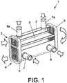
- a heat exchanger 1 which comprises a bundle of tubes (not shown for reasons of clarity) disposed inside a carcass 2, defining an inlet 3 and a gas outlet 4, said tubes being intended for circulation gases with a heat exchange with at least one refrigerant.
- the tubes are fixed at their ends between two support plates 5 coupled in each end of the carcass 2, the two support plates 5 having a plurality of orifices for positioning the respective tubes.
- the exchanger 1 comprises deflection means disposed inside the carcass 2 capable of directing the at least one refrigerant fluid in the carcass 2.
- the deflection means comprise a substantially parallel longitudinal deflector 6 to the bundle of tubes, for dividing the carcass 2 into two circuits.
- the deflector located in the casing 2 of the exchanger 1 makes it possible to improve the distribution of a refrigerant fluid or even to separate two different fluids, just like oil and a refrigeration fluid, without communication between the two. inside a common carcass 2. Two embodiments of the deflector are shown below.
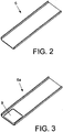
- the deflector 6 comprises a closed and homogeneous surface which allows a perfect seal between the circuits of two refrigerants.
- the purpose of said deflector 6 is to separate two different refrigerants in the interior of the carcass 2, because of their compositions, properties, etc. different.
- This type of deflector 6 is used in exchangers in which it is necessary to use different refrigerant circuits in the exchanger to produce heat exchange with the exhaust gas flowing in the tubes.
- an exchanger 1 which uses said deflector 6 to separate two types of refrigerant.
- two different inlet ducts 7, 7a, and two different outlet ducts 8, 8a are required in the same exchanger 1.
- an adequate separation of the two refrigerants in the same carcass 2 is achieved.
- entry and exit the two refrigerants in the carcass 2 and the entry and exit of the gases in the carcass 2 and their change of direction in a gas tank (not shown) are shown.
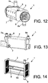
- the deflector 6a comprises a through opening 9 in its surface for the passage of a refrigerant from one half to another half of the carcass 2, to optimize the distribution of the refrigerant in the carcass 6.
- This type 6a deflector is used to increase the yields or improve the distribution of the refrigerant in the carcass 2.
- FIGs 4 and 5 illustrate an exchanger 1 which uses said deflector 6a, whose input 7 and output 8 conductors are located in the same end of the carcass 2.
- a figure 4 the inlet and outlet of the refrigerant in the carcass 2 are represented by arrows.
- the inlet 7 and the outlet 8 of the coolant have to be placed at a short distance from each other or even same end of the carcass 2, which may cause a preferable path for the coolant and affect accordingly the filling of the refrigerant and lead to poor refrigeration of the gas tubes, and also give rise to stagnation points that can cause a phenomenon boiling water may damage the heat exchanger.
- the deflector 6a provided with its opening 9 improves the circulation of the refrigerant in the exchanger.
- the configuration of the baffle 6, 6a of the present invention includes peripheral fins bent in its two longitudinal edges, as can be seen in FIG. figure 6 , intended to connect the baffle 6, 6a to two internal walls of the carcass 2, preferably by baking (see FIG. figure 7 ). In this way, the use of welding points between the deflector 6, 6a and the carcass 2 as used with the deflectors known in the state of the art is abolished.
- the deflector 6, 6a of the present invention includes in its transverse edges two projecting segments 11, as illustrated by FIGS. figures 6 , 8 and 9 , capable of fitting into respective grooves (12) made in the support plates 5 (see Figures 10 and 11 ), allowing the deflector 6, 6a to remain fixed at the appropriate position before welding.
- the mounting of the deflector 6, 6a is carried out in a manner similar to the process of mounting the tubes with said support plates 5.
- figures 1 , 12 and 13 respectively illustrate different configurations of exchangers 1 which use two refrigerants, their respective inlet ducts 4, 4a and 8a outlet 8a being arranged at different positions relative to the carcass 2.
- a closed baffle 6 is used (see figure 2 ) to separate the two refrigerants.
- figures 4 and 14 respectively show different configurations of exchangers that use the same refrigerant whose pair of inlet ducts 7 and outlet 8 is located in the same end of the carcass 2, said ducts 7, 8 being arranged at different relative positions in the casing 2.
- a deflector 6a provided with a through opening 9 (see FIG. figure 3 ) to improve the distribution of the coolant is used.
- the deflector 6, 6a of the invention can be used in exchangers made of stainless steel or aluminum.
Description
La présente invention se réfère à un échangeur thermique de gaz conforme au préambule de la revendication 1, en particulier des gaz d'échappement d'un moteur. Un tel échangeur est connu de
Dans certains échangeurs thermiques de refroidissement des gaz, par exemple ceux utilisés dans les systèmes de recyclage des gaz d'échappement vers l'admission d'un moteur à explosion, les deux milieux qui échangent de la chaleur sont séparés par une cloison.In some heat exchangers for gas cooling, for example those used in exhaust gas recirculation systems to the admission of an internal combustion engine, the two media that exchange heat are separated by a partition.
La configuration actuelle des échangeurs EGR sur le marché correspond à un échangeur thermique métallique fabriqué généralement en acier inoxydable ou en aluminium.The current configuration of EGR exchangers on the market is a metal heat exchanger typically made of stainless steel or aluminum.
Il existe essentiellement deux types d'échangeurs thermiques EGR : un premier type consiste en une carcasse à l'intérieur de laquelle est disposé un faisceau de tubes parallèles pour le passage des gaz, le réfrigérant circulant à travers la carcasse, extérieurement aux tubes, et le second type consiste en une série de plaques parallèles qui constituent les surfaces d'échange thermique, de telle sorte que les gaz d'échappement et le réfrigérant circulent entre deux plaques, en couches alternées, l'échange thermique pouvant être amélioré par l'ajout d'ailettes.There are essentially two types of EGR heat exchanger: a first type consists of a carcass inside which is disposed a bundle of parallel tubes for the passage of gases, the refrigerant flowing through the carcass, outside the tubes, and the second type consists of a series of parallel plates which constitute the heat exchange surfaces, so that the exhaust gases and the refrigerant circulate between two plates, in alternating layers, the heat exchange being able to be improved by the added fins.
Dans le cas des échangeurs thermiques à faisceau de tubes, le raccordement entre les tubes et la carcasse peut être de différents types. Généralement, les tubes sont fixés par leurs extrémités entre deux plaques de support accouplées à chaque extrémité de la carcasse, les deux plaques de support présentant une pluralité d'orifices pour le positionnement des tubes respectifs.In the case of heat exchangers with tube bundle, the connection between the tubes and the carcass can be of different types. Generally, the tubes are fixed at their ends between two support plates coupled to each end of the carcass, the two support plates having a plurality of orifices for positioning the respective tubes.
Lesdites plaques de support sont fixées à leur tour à des moyens de connexion à la conduite de recyclage, lesquels peuvent consister en une connexion en V ou bien en un rebord périphérique de connexion ou bride, selon la conception de la conduite de recyclage où est monté l'échangeur. Le rebord périphérique peut être monté avec un réservoir de gaz, si bien que le réservoir de gaz est une pièce intermédiaire entre la carcasse et le rebord, ou bien le rebord peut monté directement sur la carcasse.Said support plates are in turn attached to connection means to the recycling line, which may consist of a V-shaped connection or a peripheral flange connection or flange, according to the design of the recycling pipe where is mounted the exchanger. The peripheral rim can be mounted with a gas tank, so that the gas tank is an intermediate piece between the carcass and the rim, or the rim can be mounted directly on the carcass.
Dans les deux types d'échangeurs EGR, leurs composants sont en majeure partie métalliques, si bien qu'ils sont montés par des moyens mécaniques puis soudés au four ou soudés à l'arc ou au laser pour assurer l'étanchéité adéquate requise pour cette application. Dans certains cas, certains composants de plastique peuvent aussi être inclus, lesquels peuvent avoir une fonction unique ou bien diverses fonctions intégrées dans une seule pièce.In both types of EGR exchangers, their components are mostly metallic, so they are mounted mechanically and then oven-welded or arc-welded or laser-welded to provide the proper seal required for this purpose. application. In some cases, some plastic components may also be included, which may have a single function or various functions integrated in a single room.
La fonction principale des échangeurs EGR est l'échange thermique entre les gaz d'échappement et le fluide réfrigérant, afin de refroidir les gaz. De plus, l'échangeur EGR doit satisfaire d'autres fonctions secondaires de pouvoir être monté sur le bloc moteur, permettre la connexion avec le fluide réfrigérant, ou permettre la connexion avec le circuit de gaz d'échappement, entre autres. Actuellement, les différents composants de l'échangeur sont joints à la carcasse par soudure au four ou par soudure à l'arc ou au laser.The main function of the EGR exchangers is the heat exchange between the exhaust gas and the refrigerant, in order to cool the gases. In addition, the EGR exchanger must meet other secondary functions to be mounted on the engine block, allow connection with the refrigerant, or allow connection with the exhaust gas circuit, among others. Currently, the various components of the exchanger are joined to the carcass by welding in the oven or by arc welding or laser welding.
Certains échangeurs EGR à tubes ou plaques existant sur le marché comportent des déflecteurs, lesquels sont placés à l'intérieur du circuit du fluide réfrigérant. La conception et le nombre des déflecteurs peuvent varier d'une application à une autre, en fonction des exigences d'usage et des restrictions du constructeur de véhicules, en termes de conditions de fonctionnement ou de restrictions de conditionnement de l'échangeur.Some existing tube or plate EGR exchangers have deflectors, which are placed inside the refrigerant circuit. The design and number of baffles may vary from application to application, depending on the usage requirements and restrictions of the vehicle manufacturer, in terms of operating conditions or conditioning restrictions of the exchanger.
Dans la plupart des cas, les déflecteurs sont utilisés afin d'améliorer la circulation du fluide réfrigérant autour des tubes des gaz, évitant ainsi les points de stagnation qui pourraient causer l'ébullition du fluide réfrigérant à l'intérieur de l'échangeur, et afin d'améliorer la réfrigération de tous les tubes pour un meilleur rendement de l'échangeur.In most cases, the baffles are used to improve the circulation of the refrigerant around the tubes of gases, thus avoiding the stagnation points that could cause the boiling of the refrigerant inside the exchanger, and to improve the refrigeration of all tubes for better performance of the exchanger.
Dans d'autres cas, les déflecteurs sont inclus afin d'éviter les problèmes mécaniques qui peuvent apparaître dans les conditions de travail de l'échangeur dans le moteur.In other cases, the baffles are included to avoid mechanical problems that may occur in the working conditions of the exchanger in the engine.
On connaît un échangeur EGR qui utilise un déflecteur longitudinal qui divise l'intérieur de la carcasse en deux moitiés pour diriger en mode by-pass le fluide réfrigérant d'une moitié de la carcasse à l'autre quand les conduits d'entrée et de sortie du fluide réfrigérant se trouvent du même côté de la carcasses. Ce déflecteur est fixé à la carcasse de l'échangeur par des points de soudure et présente une longueur légèrement inférieure à la longueur de la carcasse. La demande de brevet espagnol n°
Les brevets
En général, l'utilisation de déflecteurs à l'intérieur des échangeurs thermiques se généralise et est plus fréquente ces dernières années suite à la législation environnementale et aux restrictions de conception de certains types d'échangeurs, tels que :
- les échangeurs thermiques qui permettent l'utilisation de deux circuits de fluide réfrigérant, qu'il s'agisse du même fluide ou non.
- Les échangeurs thermiques qui doivent refroidir deux fluides chauds, qu'il s'agisse du même fluide ou non.
- Les échangeurs thermiques dont les conduits d'entrée et de sortie du fluide réfrigérant se trouvent du même côté de la carcasse.
- heat exchangers that allow the use of two refrigerant circuits, whether the same fluid or not.
- Heat exchangers that must cool two hot fluids, whether the same fluid or not.
- The heat exchangers in which the inlet and outlet ducts of the refrigerant are on the same side of the carcass.
Le problème principal que pose l'usage de déflecteurs est d'assurer une étanchéité adéquate entre les deux circuits définis dans la carcasse de l'échangeur quand deux types de fluides réfrigérants sont employés, laquelle est liée à la manière de monter et de fixer ce déflecteur à l'intérieur de la carcasse, généralement au moyen de points de soudure, en respectant à la fois le comportement mécanique que doit présenter l'échangeur pour satisfaire les spécifications du constructeur de véhicules.The main problem posed by the use of baffles is to ensure an adequate seal between the two circuits defined in the shell of the exchanger when two types of coolants are used, which is related to the manner of mounting and fixing this deflector inside the carcass, usually by means of welding points, respecting both the mechanical behavior that must present the exchanger to meet the specifications of the vehicle manufacturer.
Un autre problème que présente ce type de déflecteurs est de pouvoir assurer la position et l'orientation adéquates du déflecteur quand il est monté dans la carcasse avant sa soudure.Another problem with this type of baffle is to ensure the proper position and orientation of the deflector when it is mounted in the carcass before welding.
Le but de l'échangeur thermique de gaz, en particulier des gaz d'échappement d'un moteur de la présente invention est de résoudre les inconvénients que présentent les échangeurs connus dans la technique, en fournissant un déflecteur destiné à améliorer la distribution d'un fluide réfrigérant qui circule dans l'échangeur, ou même à séparer deux fluides réfrigérants différents sans communication entre eux à l'intérieur d'une même carcasse, permettant un montage plus efficace dudit déflecteur à l'intérieur de l'échangeur.The purpose of the gas heat exchanger, in particular the exhaust gases of an engine of the present invention is to overcome the disadvantages of exchangers known in the art, by providing a baffle for improving the distribution of a refrigerant fluid that circulates in the exchanger, or even to separate two different refrigerants without communication between them within the same carcass, allowing a more effective mounting of said baffle inside the exchanger.
L'échangeur thermique de gaz, en particulier des gaz d'échappement d'un moteur, objet de la présente invention, est conforme à la revendication 1.The gas heat exchanger, in particular the exhaust gas of an engine, object of the present invention, is in accordance with
De cette façon, un positionnement et un montage plus simples du déflecteur sont réalisés à l'intérieur de la carcasse, ainsi qu'une meilleure fixation de celui-ci grâce à son raccordement par soudure. De préférence la soudure au four est employée, évitant ainsi le recours aux points de soudure comme pour les déflecteurs connus dans l'art de la technique.In this way, a simpler positioning and mounting of the deflector are made inside the carcass, and a better attachment thereof through its connection by welding. Preferably the baking is used, thus avoiding the use of soldering points as for deflectors known in the art.
Avantageusement, le déflecteur inclut dans ses bords longitudinaux deux ailettes périphériques pliées destinées à venir en contact avec les parois intérieures de la carcasse pour son raccordement par soudure.Advantageously, the deflector includes in its longitudinal edges two folded peripheral fins intended to come into contact with the inner walls of the carcass for its connection by welding.
L'utilisation desdites ailettes périphériques et des segments saillants garantit un positionnement et une orientation adéquats du déflecteur à l'intérieur de la carcasse, avant sa fixation par soudure.The use of said peripheral fins and projecting segments ensures proper positioning and orientation of the deflector within the carcass, prior to its attachment by welding.
Selon une première réalisation, le déflecteur comprend une surface fermée pour éviter la communication entre les deux circuits dans la carcasse ;In a first embodiment, the deflector comprises a closed surface to prevent communication between the two circuits in the carcass;
Dans ce cas, l'échangeur comporte deux paires de conduits d'entrée et de sortie prévus pour la distribution de deux flux de fluide réfrigérant différents.In this case, the exchanger comprises two pairs of inlet and outlet ducts provided for the distribution of two different refrigerant fluid streams.
Selon une seconde réalisation, le déflecteur comprend une ouverture traversante dans sa surface capable de mettre en communication deux circuits dans la carcasse.According to a second embodiment, the deflector comprises a through opening in its surface capable of communicating two circuits in the carcass.
Dans cet autre cas, l'échangeur comporte une paire de conduits d'entrée et de sortie disposés dans une même extrémité de la carcasse pour la distribution d'un flux de fluide réfrigérant.In this other case, the exchanger comprises a pair of inlet and outlet conduits disposed in the same end of the carcass for dispensing a flow of refrigerant fluid.
Afin de faciliter la description de ce qui a été susmentionné, nous joignons des dessins qui représentent, schématiquement et uniquement à titre d'exemple non limitatif, un cas pratique de réalisation de l'échangeur thermique de gaz, en particulier des gaz d'échappement d'un moteur de l'invention, dans lesquels :
- la
figure 1 est une vue en perspective et partiellement en coupe de l'échangeur thermique de l'invention, montrant l'emplacement du déflecteur et les deux circuits par lesquels circulent respectivement deux fluides réfrigérants ; - la
figure 2 est une vue en perspective du déflecteur selon une première réalisation de l'invention ; - la
figure 3 est une vue en perspective du déflecteur selon une seconde réalisation de l'invention ; - la
figure 4 est une vue en perspective d'un type d'échangeur qui utilise un même type de fluide réfrigérant avec ses conduits d'entrée et de sortie situés dans une même extrémité de la carcasse ; - la
figure 5 est une vue en coupe de l'échangeur de lafigure 4 , montrant le déflecteur utilisé et le parcours du fluide réfrigérant ; - la
figure 6 est une vue en perspective d'un déflecteur montrant les ailettes longitudinales de fixation ; - la
figure 7 est une vue partielle en perspective de la carcasse de l'échangeur, montrant le déflecteur monté et fixé aux parois internes de la carcasse grâce aux ailettes longitudinales ; - les
figures 8 et 9 sont des vues en perspective et en plan respectivement d'une extrémité du déflecteur selon l'invention, montrant un segment saillant prévu pour l'emboîtement avec une plaque de support des tubes ; - la
figure 10 est une vue en perspective d'une plaque de support, montrant une rainure d'emboîtement destinée à recevoir le segment saillant du déflecteur ; - la
figure 11 est une vue en perspective du déflecteur monté dans la plaque de support illustrée à lafigure 10 ; - les
figures 12 et 13 sont respectivement des vues en perspective de deux configurations d'échangeurs thermiques qui utilisent deux types de fluides réfrigérants différents, montrant l'emplacement des paires respectives de conduits d'entrée et de sortie des deux fluides réfrigérants ; et - la
figure 14 est une vue en coupe et en perspective d'un échangeur thermique qui utilise un fluide réfrigérant unique, montrant l'emplacement de la paire de conducteurs d'entrée et de sortie situés dans une même extrémité de la carcasse.
- the
figure 1 is a perspective view and partially in section of the heat exchanger of the invention, showing the location of the deflector and the two circuits through which respectively circulating two refrigerants; - the
figure 2 is a perspective view of the deflector according to a first embodiment of the invention; - the
figure 3 is a perspective view of the deflector according to a second embodiment of the invention; - the
figure 4 is a perspective view of a type of exchanger that uses the same type of refrigerant with its inlet and outlet ducts located in the same end of the carcass; - the
figure 5 is a sectional view of the exchanger of thefigure 4 showing the deflector used and the refrigerant flow; - the
figure 6 is a perspective view of a deflector showing the longitudinal fixing fins; - the
figure 7 is a partial perspective view of the carcass of the exchanger, showing the deflector mounted and fixed to the internal walls of the carcass with the longitudinal fins; - the
Figures 8 and 9 are views in perspective and in plan respectively of one end of the deflector according to the invention, showing a projecting segment provided for interlocking with a support plate of the tubes; - the
figure 10 is a perspective view of a support plate, showing an interlocking groove for receiving the projecting segment of the deflector; - the
figure 11 is a perspective view of the deflector mounted in the support plate shown in FIG.figure 10 ; - the
Figures 12 and 13 are respectively perspective views of two configurations of heat exchangers that use two different types of coolant fluids, showing the location of the respective pairs of inlet and outlet conduits of the two refrigerant fluids; and - the
figure 14 is a sectional view in perspective of a heat exchanger that uses a single refrigerant, showing the location of the pair of input and output conductors located in the same end of the carcass.
A la
Ainsi, l'échangeur 1 comporte des moyens de déviation disposés à l'intérieur de la carcasse 2 susceptibles de diriger l'au moins un fluide réfrigérant dans la carcasse 2. Dans ce cas, les moyens de déviation comprennent un déflecteur longitudinal 6 sensiblement parallèle au faisceau de tubes, destiné à diviser la carcasse 2 en deux circuits.Thus, the
Le déflecteur situé dans la carcasse 2 de l'échangeur 1 permet d'améliorer la distribution d'un fluide réfrigérant ou même de séparer deux fluides différents, tout comme de l'huile et un fluide de réfrigération, sans communication entre les deux à l'intérieur d'une carcasse 2 commune. Deux réalisations du déflecteur sont montrées ci-après.The deflector located in the
Selon une première réalisation montrée à la
A la
Selon une seconde réalisation montrée à la
Les
En raison des restrictions de conditionnement ou des impératifs du constructeur de véhicules, il est possible que les conducteurs d'entrée 7 et de sortie 8 du fluide réfrigérant aient à être placés à une courte distance l'un de l'autre ou même dans la même extrémité de la carcasse 2, ce qui peut occasionner un trajet préférable pour le fluide réfrigérant et affecter en conséquence le remplissage du fluide réfrigérant et entraîner une mauvaise réfrigération des tubes de gaz, et donner également lieu à des points de stagnation pouvant provoquer un phénomène d'ébullition risquant d'endommager l'échangeur. Dans ce cas, le déflecteur 6a pourvu de son ouverture 9 permet d'améliorer la circulation du fluide réfrigérant dans l'échangeur.Due to packaging restrictions or requirements of the vehicle manufacturer, it is possible that the
La configuration du déflecteur 6, 6a de la présente invention inclut des ailettes périphériques pliées 10 dans ses deux bords longitudinaux, comme on le peut le voir à la
Ainsi, le déflecteur 6, 6a de la présente invention inclut dans ses bords transversaux deux segments saillants 11, comme l'illustrent les
A titre d'exemple, les
D'autre part, les
Le déflecteur 6, 6a de l'invention peut être utilisé dans des échangeurs fabriqués en acier inoxydable ou en aluminium.The
Claims (6)
- Heat exchanger (1) for gas, in particular the exhaust gases of an engine, comprising a bundle of tubes arranged inside a shell (2) and intended for the circulation of gas with an exchange of heat with at least one stream of refrigerant fluid, said tubes being fixed by their ends between two support plates (5) coupled at each end of the shell (2), and deflection means arranged inside the shell (2) able to direct the at least one stream of refrigerant fluid inside the shell (2), the deflection means comprising a longitudinal deflector (6, 6a) substantially parallel to the tube bundle and intended to divide the shell (2) into two circuits, said deflector (6, 6a) being fixed by its longitudinal edges to the internal walls of the shell (2) and by its transverse edges to the two support plates (5) by welding, characterized in that the deflector (6, 6a) includes in its transverse edges two protruding segments (11) able to engage in respective grooves (12) produced in the support plates (5) for its connection by welding.
- Exchanger (1) according to Claim 1, wherein the deflector (6, 6a) includes in its longitudinal edges two folded peripheral fins (10) intended to come into contact with the internal walls of the shell (2) for its connection by welding.
- Exchanger (1) according to Claim 1, wherein the deflector (6) comprises a closed surface to prevent communication between the two circuits in the shell (2).
- Exchanger (1) according to Claim 3, which includes two pairs of inlet pipes (7, 7a) and outlet pipes (8, 8a) provided for distribution of two different streams of refrigerant fluid.
- Exchanger (1) according to Claim 1, wherein the deflector (6a) comprises a through opening (9) in its surface able to bring the two circuits into communication in the shell (2).
- Exchanger (1) according to Claim 5, comprising a pair of inlet (7) and outlet pipes (8) arranged at a same end of the shell (2) for distribution of a stream of refrigerant fluid.
Applications Claiming Priority (2)
| Application Number | Priority Date | Filing Date | Title |
|---|---|---|---|
| ES201231479A ES2450791B1 (en) | 2012-09-25 | 2012-09-25 | Heat exchanger for gases, especially the exhaust gases of an engine |
| PCT/EP2013/069863 WO2014048923A1 (en) | 2012-09-25 | 2013-09-24 | Heat exchanger for gas, particularly the exhaust gases of an engine |
Publications (2)
| Publication Number | Publication Date |
|---|---|
| EP2901098A1 EP2901098A1 (en) | 2015-08-05 |
| EP2901098B1 true EP2901098B1 (en) | 2017-03-15 |
Family
ID=49230798
Family Applications (1)
| Application Number | Title | Priority Date | Filing Date |
|---|---|---|---|
| EP13766112.0A Active EP2901098B1 (en) | 2012-09-25 | 2013-09-24 | Heat exchanger for gas, particularly the exhaust gases of an engine |
Country Status (5)
| Country | Link |
|---|---|
| US (1) | US20150253085A1 (en) |
| EP (1) | EP2901098B1 (en) |
| KR (1) | KR20150056860A (en) |
| ES (2) | ES2450791B1 (en) |
| WO (1) | WO2014048923A1 (en) |
Families Citing this family (9)
| Publication number | Priority date | Publication date | Assignee | Title |
|---|---|---|---|---|
| DE102014208259A1 (en) * | 2014-04-30 | 2015-11-05 | Mtu Friedrichshafen Gmbh | Cooling device for cooling a fluid medium, exhaust gas recirculation system for an internal combustion engine and internal combustion engine |
| CN103994672B (en) * | 2014-05-16 | 2016-08-24 | 山东鲁润热能科技有限公司 | Efficiently two-chamber turbulent heat transfer device |
| CN106871670A (en) * | 2015-12-10 | 2017-06-20 | 莱尔德电子材料(深圳)有限公司 | Heat exchanger |
| ES2632687B1 (en) * | 2016-03-14 | 2018-06-25 | Valeo Térmico, S. A. | HEAT EXCHANGER FOR GASES, ESPECIALLY OF EXHAUST GASES OF AN ENGINE |
| DE102018109688A1 (en) * | 2018-04-23 | 2019-10-24 | Volkswagen Aktiengesellschaft | Exhaust gas recirculation arrangement with heat exchanger, heat exchanger and internal combustion engine |
| ES2729205A1 (en) * | 2018-04-30 | 2019-10-30 | Valeo Termico Sa | HEAT EXCHANGER FOR GASES, ESPECIALLY OF EXHAUST GASES OF AN ENGINE (Machine-translation by Google Translate, not legally binding) |
| ES2732676A1 (en) * | 2018-05-24 | 2019-11-25 | Valeo Termico Sa | HEAT EXCHANGER FOR GASES, ESPECIALLY OF EXHAUST GASES OF AN ENGINE (Machine-translation by Google Translate, not legally binding) |
| CN111829370A (en) * | 2020-07-28 | 2020-10-27 | 贵州永红航空机械有限责任公司 | Heat exchanger and heat exchange method |
| CN114440662A (en) * | 2020-10-30 | 2022-05-06 | 江西省瑞科制冷科技有限公司 | Injection molding heat exchanger device |
Family Cites Families (11)
| Publication number | Priority date | Publication date | Assignee | Title |
|---|---|---|---|---|
| GB799571A (en) * | 1955-06-14 | 1958-08-13 | United Aircraft Prod | Heat exchange apparatus |
| DE2742462C3 (en) * | 1977-09-21 | 1981-05-27 | M.A.N. Maschinenfabrik Augsburg-Nürnberg AG, 8000 München | Cylindrical heat exchanger with several hollow cylinders arranged one inside the other |
| DE3826244C2 (en) * | 1988-08-02 | 1995-03-23 | Laengerer & Reich Kuehler | oil cooler |
| JP4089804B2 (en) | 1999-03-31 | 2008-05-28 | 日産ディーゼル工業株式会社 | EGR cooler device |
| JP4247942B2 (en) * | 1999-07-14 | 2009-04-02 | 臼井国際産業株式会社 | EGR gas cooling device |
| JP2002292089A (en) | 2001-03-29 | 2002-10-08 | Heiwa Corp | Game hall system |
| FR2838776B1 (en) * | 2002-04-17 | 2005-07-08 | Johnson Contr Automotive Elect | TWO-CHANNEL CIRCULATION COOLING DEVICE FOR EXHAUST GASES OF AN INTERNAL COMBUSTION ENGINE |
| WO2008092677A1 (en) * | 2007-01-31 | 2008-08-07 | Behr Gmbh & Co. Kg | Heat exchanger |
| DE102008014169A1 (en) * | 2007-04-26 | 2009-01-08 | Behr Gmbh & Co. Kg | Heat exchanger, in particular for exhaust gas cooling, system with a heat exchanger for exhaust gas cooling, method for operating a heat exchanger |
| DE202009018892U1 (en) * | 2009-01-15 | 2014-04-17 | Halla Visteon Climate Control Corporation | Heat exchanger for the exhaust system of a motor vehicle with improved temperature compensation in the coolant |
| DE102010043750B4 (en) * | 2010-11-11 | 2017-10-26 | Halla Visteon Climate Control Corporation | Apparatus and method for exhaust gas cooling in motor vehicles |
-
2012
- 2012-09-25 ES ES201231479A patent/ES2450791B1/en not_active Expired - Fee Related
-
2013
- 2013-09-24 WO PCT/EP2013/069863 patent/WO2014048923A1/en active Application Filing
- 2013-09-24 ES ES13766112.0T patent/ES2625115T3/en active Active
- 2013-09-24 US US14/431,138 patent/US20150253085A1/en not_active Abandoned
- 2013-09-24 KR KR1020157010577A patent/KR20150056860A/en active Search and Examination
- 2013-09-24 EP EP13766112.0A patent/EP2901098B1/en active Active
Non-Patent Citations (1)
| Title |
|---|
| None * |
Also Published As
| Publication number | Publication date |
|---|---|
| ES2450791A1 (en) | 2014-03-25 |
| KR20150056860A (en) | 2015-05-27 |
| ES2625115T3 (en) | 2017-07-18 |
| EP2901098A1 (en) | 2015-08-05 |
| ES2450791B1 (en) | 2015-01-16 |
| US20150253085A1 (en) | 2015-09-10 |
| WO2014048923A1 (en) | 2014-04-03 |
Similar Documents
| Publication | Publication Date | Title |
|---|---|---|
| EP2901098B1 (en) | Heat exchanger for gas, particularly the exhaust gases of an engine | |
| EP2726804B1 (en) | Heat exchanger, particularly for a motor vehicle | |
| EP1444473B1 (en) | Heat exchanger module comprising a main radiator and a secondary radiator | |
| FR2902507A1 (en) | HEAT EXCHANGER | |
| WO2013050396A1 (en) | Plate for a heat exchanger and heat exchanger equipped with such plates | |
| EP1558886B1 (en) | Management system for the thermal energy generated by a thermal engine in an automobile vehicle | |
| EP3117173B1 (en) | Connection device for heat exchanger and heat exchanger provided with said connection device | |
| WO2011061090A2 (en) | Heat exchanger for gases, in particular for the exhaust gases of an engine | |
| WO2014001366A1 (en) | Heat exchanger, particularly motor vehicle engine charge air cooler | |
| WO2012080039A2 (en) | Stacked plate heat exchanger | |
| FR3008485A1 (en) | HEAT EXCHANGER | |
| EP2926077B1 (en) | Gas heat exchanger, in particular for exhaust gases of an engine | |
| FR2936043A1 (en) | Heat exchanger i.e. charge air cooler, for turbocharged engine of vehicle, has charge air circulation tubes for circulating charge air, and case for receiving tubes, where tubes are formed by case and two plates that are brazed on case | |
| FR2962200A1 (en) | Exchange unit for bundle of heat exchanger of motor vehicle in air conditioning field of vehicle, has tube block whose right end is assembled in connection opening to permit communication between volume of channel and volume of tubes | |
| FR2992713A1 (en) | Beam for heat exchanger of car, has tubes stacked in stacking direction, where tubes include raised portions that are in contact with each other by stack of tubes, so as to form partition wall of fluids for manifold of heat exchanger | |
| EP3449197B1 (en) | Heat exchanger made from plastic material and vehicle comprising said heat exchanger | |
| EP2463610B1 (en) | Heat exchanger, in particular for an automobile | |
| EP2810007A1 (en) | Heat exchanger, corresponding flat tube and corresponding plate | |
| EP2901097B1 (en) | Heat exchanger, in particular for motor vehicle, and associated assembly method | |
| EP2469210B1 (en) | Heat exchanger with stacked plates | |
| FR3026474B1 (en) | THERMAL STORAGE DEVICE, THERMAL ENERGY EXCHANGE MODULE, AND AIR CONDITIONING PLANT COMPRISING SAID DEVICE | |
| FR3024771A1 (en) | HEAT EXCHANGER BEAM AND HEAT EXCHANGER COMPRISING SAID BEAM | |
| FR3042262A1 (en) | THERMAL EXCHANGER COMPRISING AT LEAST ONE LINK TUBE | |
| FR3039264A1 (en) | HOUSING FOR A HEAT EXCHANGER AND HEAT EXCHANGER COMPRISING SAID HOUSING | |
| WO2004090448A2 (en) | Heat exchange module particularly for a motor vehicle |
Legal Events
| Date | Code | Title | Description |
|---|---|---|---|
| PUAI | Public reference made under article 153(3) epc to a published international application that has entered the european phase |
Free format text: ORIGINAL CODE: 0009012 |
|
| 17P | Request for examination filed |
Effective date: 20150416 |
|
| AK | Designated contracting states |
Kind code of ref document: A1 Designated state(s): AL AT BE BG CH CY CZ DE DK EE ES FI FR GB GR HR HU IE IS IT LI LT LU LV MC MK MT NL NO PL PT RO RS SE SI SK SM TR |
|
| AX | Request for extension of the european patent |
Extension state: BA ME |
|
| DAX | Request for extension of the european patent (deleted) | ||
| REG | Reference to a national code |
Ref country code: DE Ref legal event code: R079 Ref document number: 602013018613 Country of ref document: DE Free format text: PREVIOUS MAIN CLASS: F28F0009220000 Ipc: F02M0026000000 |
|
| RIC1 | Information provided on ipc code assigned before grant |
Ipc: F02M 26/00 20160101AFI20160601BHEP |
|
| GRAP | Despatch of communication of intention to grant a patent |
Free format text: ORIGINAL CODE: EPIDOSNIGR1 |
|
| INTG | Intention to grant announced |
Effective date: 20161013 |
|
| GRAS | Grant fee paid |
Free format text: ORIGINAL CODE: EPIDOSNIGR3 |
|
| GRAA | (expected) grant |
Free format text: ORIGINAL CODE: 0009210 |
|
| AK | Designated contracting states |
Kind code of ref document: B1 Designated state(s): AL AT BE BG CH CY CZ DE DK EE ES FI FR GB GR HR HU IE IS IT LI LT LU LV MC MK MT NL NO PL PT RO RS SE SI SK SM TR |
|
| REG | Reference to a national code |
Ref country code: CH Ref legal event code: EP Ref country code: GB Ref legal event code: FG4D Free format text: NOT ENGLISH |
|
| REG | Reference to a national code |
Ref country code: IE Ref legal event code: FG4D Free format text: LANGUAGE OF EP DOCUMENT: FRENCH |
|
| REG | Reference to a national code |
Ref country code: AT Ref legal event code: REF Ref document number: 875859 Country of ref document: AT Kind code of ref document: T Effective date: 20170415 |
|
| REG | Reference to a national code |
Ref country code: DE Ref legal event code: R096 Ref document number: 602013018613 Country of ref document: DE |
|
| REG | Reference to a national code |
Ref country code: ES Ref legal event code: FG2A Ref document number: 2625115 Country of ref document: ES Kind code of ref document: T3 Effective date: 20170718 |
|
| REG | Reference to a national code |
Ref country code: NL Ref legal event code: MP Effective date: 20170315 |
|
| REG | Reference to a national code |
Ref country code: LT Ref legal event code: MG4D |
|
| PG25 | Lapsed in a contracting state [announced via postgrant information from national office to epo] |
Ref country code: FI Free format text: LAPSE BECAUSE OF FAILURE TO SUBMIT A TRANSLATION OF THE DESCRIPTION OR TO PAY THE FEE WITHIN THE PRESCRIBED TIME-LIMIT Effective date: 20170315 Ref country code: NO Free format text: LAPSE BECAUSE OF FAILURE TO SUBMIT A TRANSLATION OF THE DESCRIPTION OR TO PAY THE FEE WITHIN THE PRESCRIBED TIME-LIMIT Effective date: 20170615 Ref country code: LT Free format text: LAPSE BECAUSE OF FAILURE TO SUBMIT A TRANSLATION OF THE DESCRIPTION OR TO PAY THE FEE WITHIN THE PRESCRIBED TIME-LIMIT Effective date: 20170315 Ref country code: HR Free format text: LAPSE BECAUSE OF FAILURE TO SUBMIT A TRANSLATION OF THE DESCRIPTION OR TO PAY THE FEE WITHIN THE PRESCRIBED TIME-LIMIT Effective date: 20170315 Ref country code: GR Free format text: LAPSE BECAUSE OF FAILURE TO SUBMIT A TRANSLATION OF THE DESCRIPTION OR TO PAY THE FEE WITHIN THE PRESCRIBED TIME-LIMIT Effective date: 20170616 |
|
| REG | Reference to a national code |
Ref country code: AT Ref legal event code: MK05 Ref document number: 875859 Country of ref document: AT Kind code of ref document: T Effective date: 20170315 |
|
| PG25 | Lapsed in a contracting state [announced via postgrant information from national office to epo] |
Ref country code: LV Free format text: LAPSE BECAUSE OF FAILURE TO SUBMIT A TRANSLATION OF THE DESCRIPTION OR TO PAY THE FEE WITHIN THE PRESCRIBED TIME-LIMIT Effective date: 20170315 Ref country code: BG Free format text: LAPSE BECAUSE OF FAILURE TO SUBMIT A TRANSLATION OF THE DESCRIPTION OR TO PAY THE FEE WITHIN THE PRESCRIBED TIME-LIMIT Effective date: 20170615 Ref country code: SE Free format text: LAPSE BECAUSE OF FAILURE TO SUBMIT A TRANSLATION OF THE DESCRIPTION OR TO PAY THE FEE WITHIN THE PRESCRIBED TIME-LIMIT Effective date: 20170315 Ref country code: RS Free format text: LAPSE BECAUSE OF FAILURE TO SUBMIT A TRANSLATION OF THE DESCRIPTION OR TO PAY THE FEE WITHIN THE PRESCRIBED TIME-LIMIT Effective date: 20170315 |
|
| PG25 | Lapsed in a contracting state [announced via postgrant information from national office to epo] |
Ref country code: NL Free format text: LAPSE BECAUSE OF FAILURE TO SUBMIT A TRANSLATION OF THE DESCRIPTION OR TO PAY THE FEE WITHIN THE PRESCRIBED TIME-LIMIT Effective date: 20170315 |
|
| REG | Reference to a national code |
Ref country code: FR Ref legal event code: PLFP Year of fee payment: 5 |
|
| PG25 | Lapsed in a contracting state [announced via postgrant information from national office to epo] |
Ref country code: EE Free format text: LAPSE BECAUSE OF FAILURE TO SUBMIT A TRANSLATION OF THE DESCRIPTION OR TO PAY THE FEE WITHIN THE PRESCRIBED TIME-LIMIT Effective date: 20170315 Ref country code: IT Free format text: LAPSE BECAUSE OF FAILURE TO SUBMIT A TRANSLATION OF THE DESCRIPTION OR TO PAY THE FEE WITHIN THE PRESCRIBED TIME-LIMIT Effective date: 20170315 Ref country code: SK Free format text: LAPSE BECAUSE OF FAILURE TO SUBMIT A TRANSLATION OF THE DESCRIPTION OR TO PAY THE FEE WITHIN THE PRESCRIBED TIME-LIMIT Effective date: 20170315 Ref country code: RO Free format text: LAPSE BECAUSE OF FAILURE TO SUBMIT A TRANSLATION OF THE DESCRIPTION OR TO PAY THE FEE WITHIN THE PRESCRIBED TIME-LIMIT Effective date: 20170315 Ref country code: AT Free format text: LAPSE BECAUSE OF FAILURE TO SUBMIT A TRANSLATION OF THE DESCRIPTION OR TO PAY THE FEE WITHIN THE PRESCRIBED TIME-LIMIT Effective date: 20170315 |
|
| PG25 | Lapsed in a contracting state [announced via postgrant information from national office to epo] |
Ref country code: SM Free format text: LAPSE BECAUSE OF FAILURE TO SUBMIT A TRANSLATION OF THE DESCRIPTION OR TO PAY THE FEE WITHIN THE PRESCRIBED TIME-LIMIT Effective date: 20170315 Ref country code: PT Free format text: LAPSE BECAUSE OF FAILURE TO SUBMIT A TRANSLATION OF THE DESCRIPTION OR TO PAY THE FEE WITHIN THE PRESCRIBED TIME-LIMIT Effective date: 20170717 Ref country code: PL Free format text: LAPSE BECAUSE OF FAILURE TO SUBMIT A TRANSLATION OF THE DESCRIPTION OR TO PAY THE FEE WITHIN THE PRESCRIBED TIME-LIMIT Effective date: 20170315 Ref country code: IS Free format text: LAPSE BECAUSE OF FAILURE TO SUBMIT A TRANSLATION OF THE DESCRIPTION OR TO PAY THE FEE WITHIN THE PRESCRIBED TIME-LIMIT Effective date: 20170715 |
|
| REG | Reference to a national code |
Ref country code: DE Ref legal event code: R097 Ref document number: 602013018613 Country of ref document: DE |
|
| PLBE | No opposition filed within time limit |
Free format text: ORIGINAL CODE: 0009261 |
|
| STAA | Information on the status of an ep patent application or granted ep patent |
Free format text: STATUS: NO OPPOSITION FILED WITHIN TIME LIMIT |
|
| PG25 | Lapsed in a contracting state [announced via postgrant information from national office to epo] |
Ref country code: DK Free format text: LAPSE BECAUSE OF FAILURE TO SUBMIT A TRANSLATION OF THE DESCRIPTION OR TO PAY THE FEE WITHIN THE PRESCRIBED TIME-LIMIT Effective date: 20170315 |
|
| 26N | No opposition filed |
Effective date: 20171218 |
|
| PG25 | Lapsed in a contracting state [announced via postgrant information from national office to epo] |
Ref country code: SI Free format text: LAPSE BECAUSE OF FAILURE TO SUBMIT A TRANSLATION OF THE DESCRIPTION OR TO PAY THE FEE WITHIN THE PRESCRIBED TIME-LIMIT Effective date: 20170315 |
|
| REG | Reference to a national code |
Ref country code: CH Ref legal event code: PL |
|
| GBPC | Gb: european patent ceased through non-payment of renewal fee |
Effective date: 20170924 |
|
| PG25 | Lapsed in a contracting state [announced via postgrant information from national office to epo] |
Ref country code: MC Free format text: LAPSE BECAUSE OF FAILURE TO SUBMIT A TRANSLATION OF THE DESCRIPTION OR TO PAY THE FEE WITHIN THE PRESCRIBED TIME-LIMIT Effective date: 20170315 |
|
| REG | Reference to a national code |
Ref country code: IE Ref legal event code: MM4A |
|
| REG | Reference to a national code |
Ref country code: BE Ref legal event code: MM Effective date: 20170930 |
|
| PG25 | Lapsed in a contracting state [announced via postgrant information from national office to epo] |
Ref country code: LU Free format text: LAPSE BECAUSE OF NON-PAYMENT OF DUE FEES Effective date: 20170924 |
|
| PG25 | Lapsed in a contracting state [announced via postgrant information from national office to epo] |
Ref country code: LI Free format text: LAPSE BECAUSE OF NON-PAYMENT OF DUE FEES Effective date: 20170930 Ref country code: CH Free format text: LAPSE BECAUSE OF NON-PAYMENT OF DUE FEES Effective date: 20170930 Ref country code: GB Free format text: LAPSE BECAUSE OF NON-PAYMENT OF DUE FEES Effective date: 20170924 Ref country code: IE Free format text: LAPSE BECAUSE OF NON-PAYMENT OF DUE FEES Effective date: 20170924 |
|
| PG25 | Lapsed in a contracting state [announced via postgrant information from national office to epo] |
Ref country code: BE Free format text: LAPSE BECAUSE OF NON-PAYMENT OF DUE FEES Effective date: 20170930 |
|
| PG25 | Lapsed in a contracting state [announced via postgrant information from national office to epo] |
Ref country code: MT Free format text: LAPSE BECAUSE OF FAILURE TO SUBMIT A TRANSLATION OF THE DESCRIPTION OR TO PAY THE FEE WITHIN THE PRESCRIBED TIME-LIMIT Effective date: 20170315 |
|
| REG | Reference to a national code |
Ref country code: FR Ref legal event code: PLFP Year of fee payment: 6 |
|
| PG25 | Lapsed in a contracting state [announced via postgrant information from national office to epo] |
Ref country code: HU Free format text: LAPSE BECAUSE OF FAILURE TO SUBMIT A TRANSLATION OF THE DESCRIPTION OR TO PAY THE FEE WITHIN THE PRESCRIBED TIME-LIMIT; INVALID AB INITIO Effective date: 20130924 |
|
| PG25 | Lapsed in a contracting state [announced via postgrant information from national office to epo] |
Ref country code: CY Free format text: LAPSE BECAUSE OF FAILURE TO SUBMIT A TRANSLATION OF THE DESCRIPTION OR TO PAY THE FEE WITHIN THE PRESCRIBED TIME-LIMIT Effective date: 20170315 |
|
| PG25 | Lapsed in a contracting state [announced via postgrant information from national office to epo] |
Ref country code: MK Free format text: LAPSE BECAUSE OF FAILURE TO SUBMIT A TRANSLATION OF THE DESCRIPTION OR TO PAY THE FEE WITHIN THE PRESCRIBED TIME-LIMIT Effective date: 20170315 |
|
| PG25 | Lapsed in a contracting state [announced via postgrant information from national office to epo] |
Ref country code: TR Free format text: LAPSE BECAUSE OF FAILURE TO SUBMIT A TRANSLATION OF THE DESCRIPTION OR TO PAY THE FEE WITHIN THE PRESCRIBED TIME-LIMIT Effective date: 20170315 |
|
| PG25 | Lapsed in a contracting state [announced via postgrant information from national office to epo] |
Ref country code: AL Free format text: LAPSE BECAUSE OF FAILURE TO SUBMIT A TRANSLATION OF THE DESCRIPTION OR TO PAY THE FEE WITHIN THE PRESCRIBED TIME-LIMIT Effective date: 20170315 |
|
| PGFP | Annual fee paid to national office [announced via postgrant information from national office to epo] |
Ref country code: CZ Payment date: 20210818 Year of fee payment: 9 |
|
| PGFP | Annual fee paid to national office [announced via postgrant information from national office to epo] |
Ref country code: ES Payment date: 20211005 Year of fee payment: 9 |
|
| PG25 | Lapsed in a contracting state [announced via postgrant information from national office to epo] |
Ref country code: CZ Free format text: LAPSE BECAUSE OF NON-PAYMENT OF DUE FEES Effective date: 20220924 |
|
| P01 | Opt-out of the competence of the unified patent court (upc) registered |
Effective date: 20230603 |
|
| REG | Reference to a national code |
Ref country code: ES Ref legal event code: FD2A Effective date: 20231102 |
|
| PGFP | Annual fee paid to national office [announced via postgrant information from national office to epo] |
Ref country code: FR Payment date: 20230927 Year of fee payment: 11 Ref country code: DE Payment date: 20230911 Year of fee payment: 11 |
|
| PG25 | Lapsed in a contracting state [announced via postgrant information from national office to epo] |
Ref country code: ES Free format text: LAPSE BECAUSE OF NON-PAYMENT OF DUE FEES Effective date: 20220925 |
|
| PG25 | Lapsed in a contracting state [announced via postgrant information from national office to epo] |
Ref country code: ES Free format text: LAPSE BECAUSE OF NON-PAYMENT OF DUE FEES Effective date: 20220925 |