EP2900927B2 - Attache auto-serrante pour aube de turbine en cmc - Google Patents
Attache auto-serrante pour aube de turbine en cmc Download PDFInfo
- Publication number
- EP2900927B2 EP2900927B2 EP13785489.9A EP13785489A EP2900927B2 EP 2900927 B2 EP2900927 B2 EP 2900927B2 EP 13785489 A EP13785489 A EP 13785489A EP 2900927 B2 EP2900927 B2 EP 2900927B2
- Authority
- EP
- European Patent Office
- Prior art keywords
- plane
- turbine
- vane
- oriented
- face
- Prior art date
- Legal status (The legal status is an assumption and is not a legal conclusion. Google has not performed a legal analysis and makes no representation as to the accuracy of the status listed.)
- Active
Links
Images
Classifications
-
- F—MECHANICAL ENGINEERING; LIGHTING; HEATING; WEAPONS; BLASTING
- F01—MACHINES OR ENGINES IN GENERAL; ENGINE PLANTS IN GENERAL; STEAM ENGINES
- F01D—NON-POSITIVE DISPLACEMENT MACHINES OR ENGINES, e.g. STEAM TURBINES
- F01D5/00—Blades; Blade-carrying members; Heating, heat-insulating, cooling or antivibration means on the blades or the members
- F01D5/30—Fixing blades to rotors; Blade roots ; Blade spacers
- F01D5/3007—Fixing blades to rotors; Blade roots ; Blade spacers of axial insertion type
-
- F—MECHANICAL ENGINEERING; LIGHTING; HEATING; WEAPONS; BLASTING
- F01—MACHINES OR ENGINES IN GENERAL; ENGINE PLANTS IN GENERAL; STEAM ENGINES
- F01D—NON-POSITIVE DISPLACEMENT MACHINES OR ENGINES, e.g. STEAM TURBINES
- F01D5/00—Blades; Blade-carrying members; Heating, heat-insulating, cooling or antivibration means on the blades or the members
- F01D5/12—Blades
- F01D5/26—Antivibration means not restricted to blade form or construction or to blade-to-blade connections or to the use of particular materials
-
- F—MECHANICAL ENGINEERING; LIGHTING; HEATING; WEAPONS; BLASTING
- F01—MACHINES OR ENGINES IN GENERAL; ENGINE PLANTS IN GENERAL; STEAM ENGINES
- F01D—NON-POSITIVE DISPLACEMENT MACHINES OR ENGINES, e.g. STEAM TURBINES
- F01D5/00—Blades; Blade-carrying members; Heating, heat-insulating, cooling or antivibration means on the blades or the members
- F01D5/12—Blades
- F01D5/28—Selecting particular materials; Particular measures relating thereto; Measures against erosion or corrosion
- F01D5/284—Selection of ceramic materials
-
- F—MECHANICAL ENGINEERING; LIGHTING; HEATING; WEAPONS; BLASTING
- F01—MACHINES OR ENGINES IN GENERAL; ENGINE PLANTS IN GENERAL; STEAM ENGINES
- F01D—NON-POSITIVE DISPLACEMENT MACHINES OR ENGINES, e.g. STEAM TURBINES
- F01D5/00—Blades; Blade-carrying members; Heating, heat-insulating, cooling or antivibration means on the blades or the members
- F01D5/30—Fixing blades to rotors; Blade roots ; Blade spacers
- F01D5/3084—Fixing blades to rotors; Blade roots ; Blade spacers the blades being made of ceramics
-
- Y—GENERAL TAGGING OF NEW TECHNOLOGICAL DEVELOPMENTS; GENERAL TAGGING OF CROSS-SECTIONAL TECHNOLOGIES SPANNING OVER SEVERAL SECTIONS OF THE IPC; TECHNICAL SUBJECTS COVERED BY FORMER USPC CROSS-REFERENCE ART COLLECTIONS [XRACs] AND DIGESTS
- Y02—TECHNOLOGIES OR APPLICATIONS FOR MITIGATION OR ADAPTATION AGAINST CLIMATE CHANGE
- Y02T—CLIMATE CHANGE MITIGATION TECHNOLOGIES RELATED TO TRANSPORTATION
- Y02T50/00—Aeronautics or air transport
- Y02T50/60—Efficient propulsion technologies, e.g. for aircraft
Definitions
- the field of the present invention is that of turbomachines and, more particularly, that of turbine blades of these turbomachines.
- a turbomachine for an aircraft generally comprises, from upstream to downstream in the direction of the gas flow, a fan, one or more stages of compressors, for example a low pressure compressor and a high pressure compressor, a combustion chamber, one or more stages of turbines, for example a high pressure turbine and a low pressure turbine, and a gas exhaust nozzle.
- Each compressor can correspond to a turbine, the two being connected by a shaft, thus forming, for example, a high pressure body (HP) and a low pressure body (LP).
- Turbine blades are parts which are subjected to very high temperatures and to strong mechanical stresses due to the centrifugal force exerted on them.
- the performance of modern engines requires that the temperature to which the high pressure turbine blades are subjected to be as high as possible.
- these blades are traditionally made of a metallic material, but it would be advantageous to make these blades of a composite material, and in particular of a composite material with a ceramic matrix (CMC).
- CMC ceramic matrix
- the advantage of CMC parts is in fact their low density and their excellent temperature resistance.
- their main drawback lies in a lower resistance to stresses and in a susceptibility to matting, which makes them difficult to use for turbine blades.
- CMC fasteners having the conventional shape of a dovetail or bulb embedded in a tooth of the disc have highlighted several difficulties that are associated with this configuration.
- the dimensions in the case of such a dovetail being severely limited by the space available between the blades, they are subject to significant matting stresses, which are too great for CMC .
- such a device results in shapes that are difficult to produce in CMC, because they are complex. It is indeed necessary to produce a bulb, generally separating these fibers in order to insert a reinforcement between them. And the bending stresses are aggravated by the stress concentration coefficients which are due to the complexity of these shapes.
- the manufacturing tolerances of these parts which is still difficult to achieve, at the present time, for parts made of CMC.
- the object of the present invention is to remedy these drawbacks by proposing an attachment device for the turbine blades which is compatible with the production of a CMC blade and the installation of which on the disk is relatively easy and quick to put on. implemented.
- the invention relates to a turbine disk for a turbomachine comprising on its periphery a means for attaching a turbine blade comprising a blade extending above a platform and a foot extending below said platform, the root of said blade having the shape of a radially extending branch, being made of composite material and comprising at least one first face, axially oriented, planar or cylindrical, of which the direction of the generators is oriented in the direction of said platform, so as to allow the sliding of a clamping piece on said flat or cylindrical face under the action of the centrifugal force which is exerted on said blade in operation on a turbomachine, characterized in that said branch comprises at its lower end a lug forming one end of the foot and providing a radial fulcrum for cooperation with a retaining element of the blade on a turbine disk and in that the p ied is entirely located on the side of said lug relative to said first face, said hooking means comprising a first face oriented axially, flat or
- Such an angle is considered to be still sufficiently small to allow the sliding of a clamping piece of the appropriate shape, on the inclined cylindrical face of the hooking means, under the action of the centrifugal force which is exerted on said blade. in operation on a turbomachine. It should be noted that to facilitate this clamping movement, it is possible to introduce rolling elements or deformable lamellae at the interface between these parts, to eliminate all friction phenomena.
- the shape given to the root of the blade makes it possible to fix it on the disc by a clamping piece which wedges it against a cooperating wall, positioned on the disc. We can thus give a simple shape to the dawn while guaranteeing its hold on a disc.
- the simplicity of shape obtained makes it possible to produce the blade in a composite material with a ceramic matrix.
- the presence of a lug at its lower part makes it possible to have a radial support which ensures the retention of the blade.
- the fact that the vane is located entirely on the side of this lug relative to the face on which the clamping piece slides allows mounting of the vane from the external face of the disc and therefore greatly facilitates its assembly.
- the attachment means comprises two planar or cylindrical faces oriented axially, the directions of the generatrices of which converge towards one another in the direction of the interior of the disc at an angle less than or equal to 45 °, one forming support for sliding said clamping piece and the other being shaped, at its lower part, to form a radial retaining element of a blade.
- the two faces are plane, one being oriented radially and the second forming an angle less than or equal to 30 ° with the radial direction.
- the turbine disk further comprises a clamping piece comprising two plane or cylindrical faces, the direction of the generatrices of which is oriented respectively parallel to each of the two cylindrical faces of the means. hooking, said part being positioned resting against one of the flat or cylindrical faces of said hooking means.
- said clamping piece is a wedge with two plane faces, one forming an angle less than or equal to 30 ° with the other.
- the invention relates to a turbomachine comprising at least one such turbine disk.
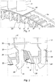
- the turbine blades comprise a blade 31 extending radially above a platform 32 which rests on the outer edge of the half-discs 1a and 1b. It is extended, moreover, below this platform, by a foot 33 which is made of a composite material of the CMC type and which has the form of a wall extending radially, that is to say perpendicular to the platform 32, and which is oriented in an axial plane, that is to say along one of the sides of said platform.
- This wall has, in radial section, the shape of a capital J, the main branch of which extends radially until it comes exceed the radial span of a spar 2; it ends with a lug, forming a hook, which is intended to pass under this spar to rest on it and ensure precise positioning of the blade relative to the disc.
- the figure 2 shows in radial section the arrangement of the various elements contributing to the maintenance of a blade 3 on a turbine disk 1.
- the spar 2 comprises circumferentially, on a first side, a substantially radial face 24, against which the radial branch 34 rests of the foot 33 and under which is placed the hook 35 forming the end of the foot 33. It comprises, on the opposite side, a face 25 aligned along an axial plane but which is inclined relative to the radial plane at an angle d 'approximately 30 °, so as to form a ramp for a clamping piece 5.
- the clamping piece has the shape of a wedge which fits between the radial branch 34 of the root of the blade and the inclined face 25 of the blade.
- spar 2 and the tip of which is oriented in the direction of the platform 32. It therefore has, on one side, a flat face oriented radially, which cooperates with the flat radial branch 34 of the root of the blade 3 and, on the other side, an inclined face, also at an angle of about 30 ° compared to port to its radial face to align parallel to the inclined face 25 of the spar 2 and cooperate with the latter so as to keep the vane 3 in position on the disc 1.
- the clamping piece 5 has a tendency, under the effect of the centrifugal field, to slide along the inclined face 25, and therefore to exert pressure against the surface 34.
- This pressure will give rise to a adhesion phenomenon, which will make it possible to take up the centrifugal forces undergone by the blade.
- the movement of the clamping part 5 vis-à-vis the inclined face 25 may optionally be facilitated by the placement of rollers or of a deformable strip between these two parts; in fact, this would make it possible to reduce the friction between these two parts.
- the figure 2 also shows, in section, an annular part with a V-shaped section, forming a spring 6 to keep the clamping part 5 in pressure against, on one side, the radial branch 34 of the root of the blade and, on the other side , the inclined face 25 of the spar 2. It extends along the circumference of the disc, a first branch of the V of this spring bearing against the internal sole of the spar 2, while the second branch of the V exerts pressure against the internal face of the clamping part 5, pushing this part outwards when the turbomachine is stationary and when no centrifugal force is exerted on it.
- the disc 1 therefore has a series of side members 2 which are carried by the two half-discs 1a and 1b and which have a free space at their lower part.
- the operator first installs the spring 6 by passing it through the space existing between two adjacent side members 2 and placing the axial end of the innermost branch of the V, inside the central bore. of the spar 2 which adjoins the vane to be mounted. It passes the clamping piece 5 in this space in the same way and comes to rest it, by its internal face, against the second branch of the V of the spring 6. Then while pushing the clamping piece 5 downwards, compressing the spring. , which moves it away from the previous spar 2, it introduces the root 33 of the blade to be mounted in the same space, until the hook 35 of the lower part of the root 33 of the blade passes under the radial branch 24 of the spar. The blade is then positioned radially by its hook and can no longer escape upwards.
- the positioning of the clamping part is ensured by the centrifugal force which is exerted during the rotation of the turbomachine, by driving the part 5 outwards and by making it rise by sliding on the inclined face 25 of the adjacent spar 2.
- the shape of the blade root 33 made of composite material is itself very simple, since it is purely rectilinear; it is therefore inexpensive to manufacture.
- the contact surface between the root 33 of the blade 3 and its clamping piece 5 can be increased as much as necessary; it is therefore possible to adjust it in order to limit the matting constraints of the composite, and thus comply with the permissible matting stress for the material of the foot.
- the mass of the clamping piece is extremely low, typically of the order of 10 grams. It is therefore possible to hollow out the side members and give them the H-shape described above, while retaining the two flat faces intended to bear against the radial branch 34 of the blade root and the inclined branch 25. of the clamping piece.
- This reduction in mass of the spar 2 associated with that obtained by the choice of the CMC material for the production of the blade, makes it possible to have a particularly light disc of reduced dimensions.
- the invention has been described with a flat face for the radial part 34 of the foot on which the clamping piece 5 slides. It is obvious that the invention can also be carried out with a non-flat face for the part of the foot in. contact with the clamping piece, provided that said clamping piece has a face which can cooperate with it in sliding outwardly of the disc.
- any cylindrical surface, the direction of the generatrices of which is oriented in the direction of said platform makes it possible to carry out the invention, since it allows the sliding of a clamping piece of the appropriate shape, under the action of the force. centrifugal which is exerted on said blade in operation on a turbomachine.
- the inclined face 25 of the side member 2 which may have a cylindrical face, the direction of the generatrices of which is oriented at an angle less than 45 ° with respect to the radial direction.
- Such an angle is considered to be still sufficiently small to allow the sliding of a clamping piece of the appropriate shape, on said inclined cylindrical face under the action of the centrifugal force which is exerted on said blade in operation on a turbomachine.
- the angle at the top of the corner constituting the clamping piece 5 is located around 30 ° so that the clamping piece provides a sufficient bearing force, without the displacement of the wedge along the faces of the pieces that it blocks is too great.
Landscapes
- Engineering & Computer Science (AREA)
- Mechanical Engineering (AREA)
- General Engineering & Computer Science (AREA)
- Chemical & Material Sciences (AREA)
- Ceramic Engineering (AREA)
- Materials Engineering (AREA)
- Turbine Rotor Nozzle Sealing (AREA)
- Structures Of Non-Positive Displacement Pumps (AREA)
Applications Claiming Priority (2)
| Application Number | Priority Date | Filing Date | Title |
|---|---|---|---|
| FR1259175A FR2996251B1 (fr) | 2012-09-28 | 2012-09-28 | Attache auto-serrante pour aube de turbine en cmc |
| PCT/FR2013/052278 WO2014049280A2 (fr) | 2012-09-28 | 2013-09-26 | Attache auto-serrante pour aube de turbine en cmc |
Publications (3)
| Publication Number | Publication Date |
|---|---|
| EP2900927A2 EP2900927A2 (fr) | 2015-08-05 |
| EP2900927B1 EP2900927B1 (fr) | 2017-11-08 |
| EP2900927B2 true EP2900927B2 (fr) | 2021-04-21 |
Family
ID=48237017
Family Applications (1)
| Application Number | Title | Priority Date | Filing Date |
|---|---|---|---|
| EP13785489.9A Active EP2900927B2 (fr) | 2012-09-28 | 2013-09-26 | Attache auto-serrante pour aube de turbine en cmc |
Country Status (9)
| Country | Link |
|---|---|
| US (1) | US10227881B2 (enExample) |
| EP (1) | EP2900927B2 (enExample) |
| JP (1) | JP6246814B2 (enExample) |
| CN (1) | CN104685162B (enExample) |
| BR (1) | BR112015006761B1 (enExample) |
| CA (1) | CA2886305C (enExample) |
| FR (1) | FR2996251B1 (enExample) |
| RU (1) | RU2664752C2 (enExample) |
| WO (1) | WO2014049280A2 (enExample) |
Families Citing this family (5)
| Publication number | Priority date | Publication date | Assignee | Title |
|---|---|---|---|---|
| US10428665B2 (en) * | 2015-12-11 | 2019-10-01 | General Electric Company | CMC thermal clamps |
| CN106968716B (zh) * | 2016-11-21 | 2017-12-19 | 北京航空航天大学 | 陶瓷基复合材料整体涡轮叶盘 |
| US10808560B2 (en) * | 2018-06-20 | 2020-10-20 | Rolls-Royce Corporation | Turbine vane assembly with ceramic matrix composite components |
| US12163547B2 (en) | 2021-03-18 | 2024-12-10 | General Electric Company | Ceramic matrix composite fastener |
| CN113623020B (zh) * | 2021-08-02 | 2022-07-08 | 无锡友鹏航空装备科技有限公司 | 一种密封性高的涡轮导向装置 |
Citations (2)
| Publication number | Priority date | Publication date | Assignee | Title |
|---|---|---|---|---|
| US2821357A (en) † | 1950-05-09 | 1958-01-28 | Maschf Augsburg Nuernberg Ag | Connection of ceramic and metallic machine parts |
| US3713752A (en) † | 1971-10-28 | 1973-01-30 | United Aircraft Corp | Composite blade for a gas turbine engine |
Family Cites Families (14)
| Publication number | Priority date | Publication date | Assignee | Title |
|---|---|---|---|---|
| BE470026A (enExample) * | 1945-12-21 | |||
| NL75780C (enExample) * | 1948-09-17 | |||
| DE818442C (de) * | 1948-10-02 | 1951-10-25 | Maschf Augsburg Nuernberg Ag | Befestigung von Schaufeln, insbesondere aus keramischen Werkstoffen, fuer Kreiselradmaschinen |
| GB914548A (en) * | 1960-03-04 | 1963-01-02 | Daimler Benz Ag | Improvements relating to wheel discs with ceramic blades for axial-flow machines |
| JPS5573806A (en) | 1978-11-24 | 1980-06-03 | Sumitomo Metal Ind Ltd | Furnace building method of blast furnace hearth part |
| SU821709A1 (ru) * | 1979-06-25 | 1981-04-15 | Предприятие П/Я А-1877 | Замковое соединение рабочихлОпАТОК C диСКОМ ТуРбиНы |
| DE3028701A1 (de) * | 1980-07-29 | 1982-02-25 | AEG-Kanis Turbinenfabrik GmbH, 8500 Nürnberg | Schaufelschloss fuer turbinenbeschaufelung |
| FR2608674B1 (fr) * | 1986-12-17 | 1991-04-19 | Snecma | Roue de turbine a aubes ceramique |
| US5074754A (en) * | 1990-04-23 | 1991-12-24 | United Technologies Corporation | Rotor blade retention system |
| JP3216956B2 (ja) * | 1994-06-08 | 2001-10-09 | 株式会社日立製作所 | ガスタービン翼固定装置 |
| DE19826897A1 (de) | 1998-06-17 | 1999-12-23 | Abb Patent Gmbh | Schloß für Laufschaufeln eines Turbinenläufers |
| FR2943942B1 (fr) | 2009-04-06 | 2016-01-29 | Snecma | Procede de fabrication d'une aube de turbomachine en materiau composite |
| US8251667B2 (en) | 2009-05-20 | 2012-08-28 | General Electric Company | Low stress circumferential dovetail attachment for rotor blades |
| US8727730B2 (en) * | 2010-04-06 | 2014-05-20 | General Electric Company | Composite turbine bucket assembly |
-
2012
- 2012-09-28 FR FR1259175A patent/FR2996251B1/fr active Active
-
2013
- 2013-09-26 CN CN201380051117.6A patent/CN104685162B/zh active Active
- 2013-09-26 RU RU2015112654A patent/RU2664752C2/ru active
- 2013-09-26 US US14/431,294 patent/US10227881B2/en active Active
- 2013-09-26 BR BR112015006761-1A patent/BR112015006761B1/pt active IP Right Grant
- 2013-09-26 JP JP2015533672A patent/JP6246814B2/ja active Active
- 2013-09-26 WO PCT/FR2013/052278 patent/WO2014049280A2/fr not_active Ceased
- 2013-09-26 CA CA2886305A patent/CA2886305C/fr active Active
- 2013-09-26 EP EP13785489.9A patent/EP2900927B2/fr active Active
Patent Citations (2)
| Publication number | Priority date | Publication date | Assignee | Title |
|---|---|---|---|---|
| US2821357A (en) † | 1950-05-09 | 1958-01-28 | Maschf Augsburg Nuernberg Ag | Connection of ceramic and metallic machine parts |
| US3713752A (en) † | 1971-10-28 | 1973-01-30 | United Aircraft Corp | Composite blade for a gas turbine engine |
Also Published As
| Publication number | Publication date |
|---|---|
| CA2886305C (fr) | 2021-01-26 |
| CN104685162B (zh) | 2017-04-12 |
| FR2996251B1 (fr) | 2018-07-27 |
| EP2900927B1 (fr) | 2017-11-08 |
| BR112015006761A2 (pt) | 2017-07-04 |
| EP2900927A2 (fr) | 2015-08-05 |
| US10227881B2 (en) | 2019-03-12 |
| FR2996251A1 (fr) | 2014-04-04 |
| JP2015530518A (ja) | 2015-10-15 |
| RU2664752C2 (ru) | 2018-08-22 |
| CN104685162A (zh) | 2015-06-03 |
| JP6246814B2 (ja) | 2017-12-13 |
| US20150275680A1 (en) | 2015-10-01 |
| RU2015112654A (ru) | 2016-11-20 |
| BR112015006761B1 (pt) | 2022-05-24 |
| WO2014049280A2 (fr) | 2014-04-03 |
| CA2886305A1 (fr) | 2014-04-03 |
| WO2014049280A3 (fr) | 2014-09-12 |
Similar Documents
| Publication | Publication Date | Title |
|---|---|---|
| EP3298244B1 (fr) | Ensemble d'anneau de turbine avec maintien axial | |
| EP1584794B1 (fr) | Disque de rotor d'une turbomachine avec un dispositif de retenue axiale d'aubes | |
| EP2900927B2 (fr) | Attache auto-serrante pour aube de turbine en cmc | |
| CA2986663C (fr) | Ensemble d'anneau de turbine avec maintien par brides | |
| EP2459884B1 (fr) | Secteur de virole exterieure pour couronne aubagee de stator de turbomachine d'aeronef, comprenant des cales amortisseuses de vibrations | |
| EP3781792B1 (fr) | Distributeur en cmc avec reprise d'effort par une pince étanche | |
| EP3312384B1 (fr) | Ensemble rotatif d'une turbomachine muni d'un système de maintien axial d'une aube | |
| EP4273370A2 (fr) | Ensemble d'anneau de turbine permettant une dilatation thermique différentielle | |
| FR3045716A1 (fr) | Ensemble d'anneau de turbine avec maintien elastique a froid | |
| CA2518355C (fr) | Retenue des clavettes de centrage des anneaux sous aubes de stator a calage variable d'un moteur a turbine a gaz | |
| FR2941487A1 (fr) | Aube de turbomachine en materiau composite a pied renforce | |
| EP4051879B1 (fr) | Turbine de turbomachine a distributeur en cmc avec reprise d'effort | |
| EP2603670B1 (fr) | Dispositif de blocage d'un pied d'une aube de rotor | |
| EP2558729B1 (fr) | Dispositif redresseur pour turbomachine | |
| WO2013107967A1 (fr) | Secteur angulaire de redresseur a amortissement de vibrations par coin pour compresseur de turbomachine | |
| EP2706242A1 (fr) | Fixation d'aubes sur un tambour de compresseur axial | |
| WO2012150425A1 (fr) | Rotor de turbomachine avec moyen de retenue axiale des aubes | |
| FR2978798A1 (fr) | Secteur angulaire de redresseur de turbomachine a amortissement des modes de vibrations | |
| EP1793093A2 (fr) | Distributeur de turbine de turbomachine amélioré | |
| EP3033495A1 (fr) | Amelioration pour le verrouillage de pieces de support d'aubage | |
| WO2013182797A1 (fr) | Turbomachine comportant des moyens de fixation amont d'un tube de deshuilage | |
| EP3710679B1 (fr) | Dispositif de maintien d'un organe de prelevement d'air radial centripete | |
| FR2960589A1 (fr) | Roue a aubes pour une turbomachine, telle qu'un turboreacteur ou un turbopropulseur d'avion | |
| FR3011270A1 (fr) | Dispositif de connexion d'une partie fixe de turbomachine et d'un pied de distributeur d'une turbine de turbomachine | |
| EP4688557A1 (fr) | Ensemble a calage variable pour soufflante de turbomachine |
Legal Events
| Date | Code | Title | Description |
|---|---|---|---|
| PUAI | Public reference made under article 153(3) epc to a published international application that has entered the european phase |
Free format text: ORIGINAL CODE: 0009012 |
|
| 17P | Request for examination filed |
Effective date: 20150318 |
|
| AK | Designated contracting states |
Kind code of ref document: A2 Designated state(s): AL AT BE BG CH CY CZ DE DK EE ES FI FR GB GR HR HU IE IS IT LI LT LU LV MC MK MT NL NO PL PT RO RS SE SI SK SM TR |
|
| AX | Request for extension of the european patent |
Extension state: BA ME |
|
| DAX | Request for extension of the european patent (deleted) | ||
| RAP1 | Party data changed (applicant data changed or rights of an application transferred) |
Owner name: SNECMA |
|
| RAP1 | Party data changed (applicant data changed or rights of an application transferred) |
Owner name: SAFRAN AIRCRAFT ENGINES |
|
| GRAP | Despatch of communication of intention to grant a patent |
Free format text: ORIGINAL CODE: EPIDOSNIGR1 |
|
| STAA | Information on the status of an ep patent application or granted ep patent |
Free format text: STATUS: GRANT OF PATENT IS INTENDED |
|
| INTG | Intention to grant announced |
Effective date: 20170822 |
|
| GRAS | Grant fee paid |
Free format text: ORIGINAL CODE: EPIDOSNIGR3 |
|
| GRAA | (expected) grant |
Free format text: ORIGINAL CODE: 0009210 |
|
| STAA | Information on the status of an ep patent application or granted ep patent |
Free format text: STATUS: THE PATENT HAS BEEN GRANTED |
|
| AK | Designated contracting states |
Kind code of ref document: B1 Designated state(s): AL AT BE BG CH CY CZ DE DK EE ES FI FR GB GR HR HU IE IS IT LI LT LU LV MC MK MT NL NO PL PT RO RS SE SI SK SM TR |
|
| REG | Reference to a national code |
Ref country code: GB Ref legal event code: FG4D Free format text: NOT ENGLISH |
|
| REG | Reference to a national code |
Ref country code: CH Ref legal event code: EP Ref country code: AT Ref legal event code: REF Ref document number: 944352 Country of ref document: AT Kind code of ref document: T Effective date: 20171115 |
|
| REG | Reference to a national code |
Ref country code: IE Ref legal event code: FG4D Free format text: LANGUAGE OF EP DOCUMENT: FRENCH |
|
| REG | Reference to a national code |
Ref country code: DE Ref legal event code: R096 Ref document number: 602013029182 Country of ref document: DE |
|
| REG | Reference to a national code |
Ref country code: SE Ref legal event code: TRGR |
|
| REG | Reference to a national code |
Ref country code: NL Ref legal event code: MP Effective date: 20171108 |
|
| REG | Reference to a national code |
Ref country code: LT Ref legal event code: MG4D |
|
| REG | Reference to a national code |
Ref country code: AT Ref legal event code: MK05 Ref document number: 944352 Country of ref document: AT Kind code of ref document: T Effective date: 20171108 |
|
| PG25 | Lapsed in a contracting state [announced via postgrant information from national office to epo] |
Ref country code: LT Free format text: LAPSE BECAUSE OF FAILURE TO SUBMIT A TRANSLATION OF THE DESCRIPTION OR TO PAY THE FEE WITHIN THE PRESCRIBED TIME-LIMIT Effective date: 20171108 Ref country code: NO Free format text: LAPSE BECAUSE OF FAILURE TO SUBMIT A TRANSLATION OF THE DESCRIPTION OR TO PAY THE FEE WITHIN THE PRESCRIBED TIME-LIMIT Effective date: 20180208 Ref country code: FI Free format text: LAPSE BECAUSE OF FAILURE TO SUBMIT A TRANSLATION OF THE DESCRIPTION OR TO PAY THE FEE WITHIN THE PRESCRIBED TIME-LIMIT Effective date: 20171108 Ref country code: NL Free format text: LAPSE BECAUSE OF FAILURE TO SUBMIT A TRANSLATION OF THE DESCRIPTION OR TO PAY THE FEE WITHIN THE PRESCRIBED TIME-LIMIT Effective date: 20171108 Ref country code: ES Free format text: LAPSE BECAUSE OF FAILURE TO SUBMIT A TRANSLATION OF THE DESCRIPTION OR TO PAY THE FEE WITHIN THE PRESCRIBED TIME-LIMIT Effective date: 20171108 |
|
| PG25 | Lapsed in a contracting state [announced via postgrant information from national office to epo] |
Ref country code: HR Free format text: LAPSE BECAUSE OF FAILURE TO SUBMIT A TRANSLATION OF THE DESCRIPTION OR TO PAY THE FEE WITHIN THE PRESCRIBED TIME-LIMIT Effective date: 20171108 Ref country code: RS Free format text: LAPSE BECAUSE OF FAILURE TO SUBMIT A TRANSLATION OF THE DESCRIPTION OR TO PAY THE FEE WITHIN THE PRESCRIBED TIME-LIMIT Effective date: 20171108 Ref country code: AT Free format text: LAPSE BECAUSE OF FAILURE TO SUBMIT A TRANSLATION OF THE DESCRIPTION OR TO PAY THE FEE WITHIN THE PRESCRIBED TIME-LIMIT Effective date: 20171108 Ref country code: LV Free format text: LAPSE BECAUSE OF FAILURE TO SUBMIT A TRANSLATION OF THE DESCRIPTION OR TO PAY THE FEE WITHIN THE PRESCRIBED TIME-LIMIT Effective date: 20171108 Ref country code: BG Free format text: LAPSE BECAUSE OF FAILURE TO SUBMIT A TRANSLATION OF THE DESCRIPTION OR TO PAY THE FEE WITHIN THE PRESCRIBED TIME-LIMIT Effective date: 20180208 Ref country code: IS Free format text: LAPSE BECAUSE OF FAILURE TO SUBMIT A TRANSLATION OF THE DESCRIPTION OR TO PAY THE FEE WITHIN THE PRESCRIBED TIME-LIMIT Effective date: 20180308 Ref country code: GR Free format text: LAPSE BECAUSE OF FAILURE TO SUBMIT A TRANSLATION OF THE DESCRIPTION OR TO PAY THE FEE WITHIN THE PRESCRIBED TIME-LIMIT Effective date: 20180209 |
|
| PG25 | Lapsed in a contracting state [announced via postgrant information from national office to epo] |
Ref country code: DK Free format text: LAPSE BECAUSE OF FAILURE TO SUBMIT A TRANSLATION OF THE DESCRIPTION OR TO PAY THE FEE WITHIN THE PRESCRIBED TIME-LIMIT Effective date: 20171108 Ref country code: SK Free format text: LAPSE BECAUSE OF FAILURE TO SUBMIT A TRANSLATION OF THE DESCRIPTION OR TO PAY THE FEE WITHIN THE PRESCRIBED TIME-LIMIT Effective date: 20171108 Ref country code: EE Free format text: LAPSE BECAUSE OF FAILURE TO SUBMIT A TRANSLATION OF THE DESCRIPTION OR TO PAY THE FEE WITHIN THE PRESCRIBED TIME-LIMIT Effective date: 20171108 Ref country code: CY Free format text: LAPSE BECAUSE OF FAILURE TO SUBMIT A TRANSLATION OF THE DESCRIPTION OR TO PAY THE FEE WITHIN THE PRESCRIBED TIME-LIMIT Effective date: 20171108 Ref country code: CZ Free format text: LAPSE BECAUSE OF FAILURE TO SUBMIT A TRANSLATION OF THE DESCRIPTION OR TO PAY THE FEE WITHIN THE PRESCRIBED TIME-LIMIT Effective date: 20171108 |
|
| REG | Reference to a national code |
Ref country code: DE Ref legal event code: R026 Ref document number: 602013029182 Country of ref document: DE |
|
| PLBI | Opposition filed |
Free format text: ORIGINAL CODE: 0009260 |
|
| PLAX | Notice of opposition and request to file observation + time limit sent |
Free format text: ORIGINAL CODE: EPIDOSNOBS2 |
|
| REG | Reference to a national code |
Ref country code: FR Ref legal event code: PLFP Year of fee payment: 6 |
|
| PG25 | Lapsed in a contracting state [announced via postgrant information from national office to epo] |
Ref country code: SM Free format text: LAPSE BECAUSE OF FAILURE TO SUBMIT A TRANSLATION OF THE DESCRIPTION OR TO PAY THE FEE WITHIN THE PRESCRIBED TIME-LIMIT Effective date: 20171108 Ref country code: PL Free format text: LAPSE BECAUSE OF FAILURE TO SUBMIT A TRANSLATION OF THE DESCRIPTION OR TO PAY THE FEE WITHIN THE PRESCRIBED TIME-LIMIT Effective date: 20171108 Ref country code: RO Free format text: LAPSE BECAUSE OF FAILURE TO SUBMIT A TRANSLATION OF THE DESCRIPTION OR TO PAY THE FEE WITHIN THE PRESCRIBED TIME-LIMIT Effective date: 20171108 |
|
| 26 | Opposition filed |
Opponent name: UNITED TECHNOLOGIES CORPORATION Effective date: 20180808 |
|
| PG25 | Lapsed in a contracting state [announced via postgrant information from national office to epo] |
Ref country code: MT Free format text: LAPSE BECAUSE OF FAILURE TO SUBMIT A TRANSLATION OF THE DESCRIPTION OR TO PAY THE FEE WITHIN THE PRESCRIBED TIME-LIMIT Effective date: 20171108 |
|
| PG25 | Lapsed in a contracting state [announced via postgrant information from national office to epo] |
Ref country code: SI Free format text: LAPSE BECAUSE OF FAILURE TO SUBMIT A TRANSLATION OF THE DESCRIPTION OR TO PAY THE FEE WITHIN THE PRESCRIBED TIME-LIMIT Effective date: 20171108 |
|
| PLBB | Reply of patent proprietor to notice(s) of opposition received |
Free format text: ORIGINAL CODE: EPIDOSNOBS3 |
|
| PG25 | Lapsed in a contracting state [announced via postgrant information from national office to epo] |
Ref country code: MC Free format text: LAPSE BECAUSE OF FAILURE TO SUBMIT A TRANSLATION OF THE DESCRIPTION OR TO PAY THE FEE WITHIN THE PRESCRIBED TIME-LIMIT Effective date: 20171108 |
|
| REG | Reference to a national code |
Ref country code: CH Ref legal event code: PL |
|
| REG | Reference to a national code |
Ref country code: BE Ref legal event code: MM Effective date: 20180930 |
|
| REG | Reference to a national code |
Ref country code: IE Ref legal event code: MM4A |
|
| PG25 | Lapsed in a contracting state [announced via postgrant information from national office to epo] |
Ref country code: LU Free format text: LAPSE BECAUSE OF NON-PAYMENT OF DUE FEES Effective date: 20180926 |
|
| PG25 | Lapsed in a contracting state [announced via postgrant information from national office to epo] |
Ref country code: IE Free format text: LAPSE BECAUSE OF NON-PAYMENT OF DUE FEES Effective date: 20180926 |
|
| PG25 | Lapsed in a contracting state [announced via postgrant information from national office to epo] |
Ref country code: BE Free format text: LAPSE BECAUSE OF NON-PAYMENT OF DUE FEES Effective date: 20180930 Ref country code: LI Free format text: LAPSE BECAUSE OF NON-PAYMENT OF DUE FEES Effective date: 20180930 Ref country code: CH Free format text: LAPSE BECAUSE OF NON-PAYMENT OF DUE FEES Effective date: 20180930 |
|
| PGFP | Annual fee paid to national office [announced via postgrant information from national office to epo] |
Ref country code: IT Payment date: 20190829 Year of fee payment: 7 Ref country code: SE Payment date: 20190826 Year of fee payment: 7 |
|
| PG25 | Lapsed in a contracting state [announced via postgrant information from national office to epo] |
Ref country code: TR Free format text: LAPSE BECAUSE OF FAILURE TO SUBMIT A TRANSLATION OF THE DESCRIPTION OR TO PAY THE FEE WITHIN THE PRESCRIBED TIME-LIMIT Effective date: 20171108 |
|
| PG25 | Lapsed in a contracting state [announced via postgrant information from national office to epo] |
Ref country code: PT Free format text: LAPSE BECAUSE OF FAILURE TO SUBMIT A TRANSLATION OF THE DESCRIPTION OR TO PAY THE FEE WITHIN THE PRESCRIBED TIME-LIMIT Effective date: 20171108 |
|
| PG25 | Lapsed in a contracting state [announced via postgrant information from national office to epo] |
Ref country code: MK Free format text: LAPSE BECAUSE OF NON-PAYMENT OF DUE FEES Effective date: 20171108 Ref country code: HU Free format text: LAPSE BECAUSE OF FAILURE TO SUBMIT A TRANSLATION OF THE DESCRIPTION OR TO PAY THE FEE WITHIN THE PRESCRIBED TIME-LIMIT; INVALID AB INITIO Effective date: 20130926 |
|
| PG25 | Lapsed in a contracting state [announced via postgrant information from national office to epo] |
Ref country code: AL Free format text: LAPSE BECAUSE OF FAILURE TO SUBMIT A TRANSLATION OF THE DESCRIPTION OR TO PAY THE FEE WITHIN THE PRESCRIBED TIME-LIMIT Effective date: 20171108 |
|
| PUAH | Patent maintained in amended form |
Free format text: ORIGINAL CODE: 0009272 |
|
| STAA | Information on the status of an ep patent application or granted ep patent |
Free format text: STATUS: PATENT MAINTAINED AS AMENDED |
|
| 27A | Patent maintained in amended form |
Effective date: 20210421 |
|
| AK | Designated contracting states |
Kind code of ref document: B2 Designated state(s): AL AT BE BG CH CY CZ DE DK EE ES FI FR GB GR HR HU IE IS IT LI LT LU LV MC MK MT NL NO PL PT RO RS SE SI SK SM TR |
|
| REG | Reference to a national code |
Ref country code: DE Ref legal event code: R102 Ref document number: 602013029182 Country of ref document: DE |
|
| PG25 | Lapsed in a contracting state [announced via postgrant information from national office to epo] |
Ref country code: SE Free format text: LAPSE BECAUSE OF NON-PAYMENT OF DUE FEES Effective date: 20200927 |
|
| REG | Reference to a national code |
Ref country code: SE Ref legal event code: EUG |
|
| PG25 | Lapsed in a contracting state [announced via postgrant information from national office to epo] |
Ref country code: IT Free format text: LAPSE BECAUSE OF NON-PAYMENT OF DUE FEES Effective date: 20200926 |
|
| PGFP | Annual fee paid to national office [announced via postgrant information from national office to epo] |
Ref country code: DE Payment date: 20250919 Year of fee payment: 13 |
|
| PGFP | Annual fee paid to national office [announced via postgrant information from national office to epo] |
Ref country code: GB Payment date: 20250923 Year of fee payment: 13 |
|
| PGFP | Annual fee paid to national office [announced via postgrant information from national office to epo] |
Ref country code: FR Payment date: 20250924 Year of fee payment: 13 |