EP2900927B2 - Self-clamping fastener for cmc turbine blade - Google Patents
Self-clamping fastener for cmc turbine blade Download PDFInfo
- Publication number
- EP2900927B2 EP2900927B2 EP13785489.9A EP13785489A EP2900927B2 EP 2900927 B2 EP2900927 B2 EP 2900927B2 EP 13785489 A EP13785489 A EP 13785489A EP 2900927 B2 EP2900927 B2 EP 2900927B2
- Authority
- EP
- European Patent Office
- Prior art keywords
- plane
- turbine
- vane
- oriented
- face
- Prior art date
- Legal status (The legal status is an assumption and is not a legal conclusion. Google has not performed a legal analysis and makes no representation as to the accuracy of the status listed.)
- Active
Links
- 239000002131 composite material Substances 0.000 claims description 10
- 238000004519 manufacturing process Methods 0.000 description 7
- 239000000463 material Substances 0.000 description 4
- 238000009434 installation Methods 0.000 description 3
- 239000000919 ceramic Substances 0.000 description 2
- 230000000694 effects Effects 0.000 description 2
- 238000005516 engineering process Methods 0.000 description 2
- 230000014759 maintenance of location Effects 0.000 description 2
- 239000011159 matrix material Substances 0.000 description 2
- 238000011144 upstream manufacturing Methods 0.000 description 2
- 208000018672 Dilatation Diseases 0.000 description 1
- 238000005452 bending Methods 0.000 description 1
- 238000002485 combustion reaction Methods 0.000 description 1
- 238000006073 displacement reaction Methods 0.000 description 1
- 239000000835 fiber Substances 0.000 description 1
- 238000012423 maintenance Methods 0.000 description 1
- 239000007769 metal material Substances 0.000 description 1
- 238000000034 method Methods 0.000 description 1
- 238000003825 pressing Methods 0.000 description 1
- 230000002787 reinforcement Effects 0.000 description 1
- 230000000284 resting effect Effects 0.000 description 1
- 238000005096 rolling process Methods 0.000 description 1
- 230000000930 thermomechanical effect Effects 0.000 description 1
Images
Classifications
-
- F—MECHANICAL ENGINEERING; LIGHTING; HEATING; WEAPONS; BLASTING
- F01—MACHINES OR ENGINES IN GENERAL; ENGINE PLANTS IN GENERAL; STEAM ENGINES
- F01D—NON-POSITIVE DISPLACEMENT MACHINES OR ENGINES, e.g. STEAM TURBINES
- F01D5/00—Blades; Blade-carrying members; Heating, heat-insulating, cooling or antivibration means on the blades or the members
- F01D5/30—Fixing blades to rotors; Blade roots ; Blade spacers
- F01D5/3007—Fixing blades to rotors; Blade roots ; Blade spacers of axial insertion type
-
- F—MECHANICAL ENGINEERING; LIGHTING; HEATING; WEAPONS; BLASTING
- F01—MACHINES OR ENGINES IN GENERAL; ENGINE PLANTS IN GENERAL; STEAM ENGINES
- F01D—NON-POSITIVE DISPLACEMENT MACHINES OR ENGINES, e.g. STEAM TURBINES
- F01D5/00—Blades; Blade-carrying members; Heating, heat-insulating, cooling or antivibration means on the blades or the members
- F01D5/12—Blades
- F01D5/26—Antivibration means not restricted to blade form or construction or to blade-to-blade connections or to the use of particular materials
-
- F—MECHANICAL ENGINEERING; LIGHTING; HEATING; WEAPONS; BLASTING
- F01—MACHINES OR ENGINES IN GENERAL; ENGINE PLANTS IN GENERAL; STEAM ENGINES
- F01D—NON-POSITIVE DISPLACEMENT MACHINES OR ENGINES, e.g. STEAM TURBINES
- F01D5/00—Blades; Blade-carrying members; Heating, heat-insulating, cooling or antivibration means on the blades or the members
- F01D5/12—Blades
- F01D5/28—Selecting particular materials; Particular measures relating thereto; Measures against erosion or corrosion
- F01D5/284—Selection of ceramic materials
-
- F—MECHANICAL ENGINEERING; LIGHTING; HEATING; WEAPONS; BLASTING
- F01—MACHINES OR ENGINES IN GENERAL; ENGINE PLANTS IN GENERAL; STEAM ENGINES
- F01D—NON-POSITIVE DISPLACEMENT MACHINES OR ENGINES, e.g. STEAM TURBINES
- F01D5/00—Blades; Blade-carrying members; Heating, heat-insulating, cooling or antivibration means on the blades or the members
- F01D5/30—Fixing blades to rotors; Blade roots ; Blade spacers
- F01D5/3084—Fixing blades to rotors; Blade roots ; Blade spacers the blades being made of ceramics
-
- Y—GENERAL TAGGING OF NEW TECHNOLOGICAL DEVELOPMENTS; GENERAL TAGGING OF CROSS-SECTIONAL TECHNOLOGIES SPANNING OVER SEVERAL SECTIONS OF THE IPC; TECHNICAL SUBJECTS COVERED BY FORMER USPC CROSS-REFERENCE ART COLLECTIONS [XRACs] AND DIGESTS
- Y02—TECHNOLOGIES OR APPLICATIONS FOR MITIGATION OR ADAPTATION AGAINST CLIMATE CHANGE
- Y02T—CLIMATE CHANGE MITIGATION TECHNOLOGIES RELATED TO TRANSPORTATION
- Y02T50/00—Aeronautics or air transport
- Y02T50/60—Efficient propulsion technologies, e.g. for aircraft
Definitions
- the field of the present invention is that of turbomachines and, more particularly, that of turbine blades of these turbomachines.
- a turbomachine for an aircraft generally comprises, from upstream to downstream in the direction of the gas flow, a fan, one or more stages of compressors, for example a low pressure compressor and a high pressure compressor, a combustion chamber, one or more stages of turbines, for example a high pressure turbine and a low pressure turbine, and a gas exhaust nozzle.
- Each compressor can correspond to a turbine, the two being connected by a shaft, thus forming, for example, a high pressure body (HP) and a low pressure body (LP).
- Turbine blades are parts which are subjected to very high temperatures and to strong mechanical stresses due to the centrifugal force exerted on them.
- the performance of modern engines requires that the temperature to which the high pressure turbine blades are subjected to be as high as possible.
- these blades are traditionally made of a metallic material, but it would be advantageous to make these blades of a composite material, and in particular of a composite material with a ceramic matrix (CMC).
- CMC ceramic matrix
- the advantage of CMC parts is in fact their low density and their excellent temperature resistance.
- their main drawback lies in a lower resistance to stresses and in a susceptibility to matting, which makes them difficult to use for turbine blades.
- CMC fasteners having the conventional shape of a dovetail or bulb embedded in a tooth of the disc have highlighted several difficulties that are associated with this configuration.
- the dimensions in the case of such a dovetail being severely limited by the space available between the blades, they are subject to significant matting stresses, which are too great for CMC .
- such a device results in shapes that are difficult to produce in CMC, because they are complex. It is indeed necessary to produce a bulb, generally separating these fibers in order to insert a reinforcement between them. And the bending stresses are aggravated by the stress concentration coefficients which are due to the complexity of these shapes.
- the manufacturing tolerances of these parts which is still difficult to achieve, at the present time, for parts made of CMC.
- the object of the present invention is to remedy these drawbacks by proposing an attachment device for the turbine blades which is compatible with the production of a CMC blade and the installation of which on the disk is relatively easy and quick to put on. implemented.
- the invention relates to a turbine disk for a turbomachine comprising on its periphery a means for attaching a turbine blade comprising a blade extending above a platform and a foot extending below said platform, the root of said blade having the shape of a radially extending branch, being made of composite material and comprising at least one first face, axially oriented, planar or cylindrical, of which the direction of the generators is oriented in the direction of said platform, so as to allow the sliding of a clamping piece on said flat or cylindrical face under the action of the centrifugal force which is exerted on said blade in operation on a turbomachine, characterized in that said branch comprises at its lower end a lug forming one end of the foot and providing a radial fulcrum for cooperation with a retaining element of the blade on a turbine disk and in that the p ied is entirely located on the side of said lug relative to said first face, said hooking means comprising a first face oriented axially, flat or
- Such an angle is considered to be still sufficiently small to allow the sliding of a clamping piece of the appropriate shape, on the inclined cylindrical face of the hooking means, under the action of the centrifugal force which is exerted on said blade. in operation on a turbomachine. It should be noted that to facilitate this clamping movement, it is possible to introduce rolling elements or deformable lamellae at the interface between these parts, to eliminate all friction phenomena.
- the shape given to the root of the blade makes it possible to fix it on the disc by a clamping piece which wedges it against a cooperating wall, positioned on the disc. We can thus give a simple shape to the dawn while guaranteeing its hold on a disc.
- the simplicity of shape obtained makes it possible to produce the blade in a composite material with a ceramic matrix.
- the presence of a lug at its lower part makes it possible to have a radial support which ensures the retention of the blade.
- the fact that the vane is located entirely on the side of this lug relative to the face on which the clamping piece slides allows mounting of the vane from the external face of the disc and therefore greatly facilitates its assembly.
- the attachment means comprises two planar or cylindrical faces oriented axially, the directions of the generatrices of which converge towards one another in the direction of the interior of the disc at an angle less than or equal to 45 °, one forming support for sliding said clamping piece and the other being shaped, at its lower part, to form a radial retaining element of a blade.
- the two faces are plane, one being oriented radially and the second forming an angle less than or equal to 30 ° with the radial direction.
- the turbine disk further comprises a clamping piece comprising two plane or cylindrical faces, the direction of the generatrices of which is oriented respectively parallel to each of the two cylindrical faces of the means. hooking, said part being positioned resting against one of the flat or cylindrical faces of said hooking means.
- said clamping piece is a wedge with two plane faces, one forming an angle less than or equal to 30 ° with the other.
- the invention relates to a turbomachine comprising at least one such turbine disk.
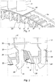
- the turbine blades comprise a blade 31 extending radially above a platform 32 which rests on the outer edge of the half-discs 1a and 1b. It is extended, moreover, below this platform, by a foot 33 which is made of a composite material of the CMC type and which has the form of a wall extending radially, that is to say perpendicular to the platform 32, and which is oriented in an axial plane, that is to say along one of the sides of said platform.
- This wall has, in radial section, the shape of a capital J, the main branch of which extends radially until it comes exceed the radial span of a spar 2; it ends with a lug, forming a hook, which is intended to pass under this spar to rest on it and ensure precise positioning of the blade relative to the disc.
- the figure 2 shows in radial section the arrangement of the various elements contributing to the maintenance of a blade 3 on a turbine disk 1.
- the spar 2 comprises circumferentially, on a first side, a substantially radial face 24, against which the radial branch 34 rests of the foot 33 and under which is placed the hook 35 forming the end of the foot 33. It comprises, on the opposite side, a face 25 aligned along an axial plane but which is inclined relative to the radial plane at an angle d 'approximately 30 °, so as to form a ramp for a clamping piece 5.
- the clamping piece has the shape of a wedge which fits between the radial branch 34 of the root of the blade and the inclined face 25 of the blade.
- spar 2 and the tip of which is oriented in the direction of the platform 32. It therefore has, on one side, a flat face oriented radially, which cooperates with the flat radial branch 34 of the root of the blade 3 and, on the other side, an inclined face, also at an angle of about 30 ° compared to port to its radial face to align parallel to the inclined face 25 of the spar 2 and cooperate with the latter so as to keep the vane 3 in position on the disc 1.
- the clamping piece 5 has a tendency, under the effect of the centrifugal field, to slide along the inclined face 25, and therefore to exert pressure against the surface 34.
- This pressure will give rise to a adhesion phenomenon, which will make it possible to take up the centrifugal forces undergone by the blade.
- the movement of the clamping part 5 vis-à-vis the inclined face 25 may optionally be facilitated by the placement of rollers or of a deformable strip between these two parts; in fact, this would make it possible to reduce the friction between these two parts.
- the figure 2 also shows, in section, an annular part with a V-shaped section, forming a spring 6 to keep the clamping part 5 in pressure against, on one side, the radial branch 34 of the root of the blade and, on the other side , the inclined face 25 of the spar 2. It extends along the circumference of the disc, a first branch of the V of this spring bearing against the internal sole of the spar 2, while the second branch of the V exerts pressure against the internal face of the clamping part 5, pushing this part outwards when the turbomachine is stationary and when no centrifugal force is exerted on it.
- the disc 1 therefore has a series of side members 2 which are carried by the two half-discs 1a and 1b and which have a free space at their lower part.
- the operator first installs the spring 6 by passing it through the space existing between two adjacent side members 2 and placing the axial end of the innermost branch of the V, inside the central bore. of the spar 2 which adjoins the vane to be mounted. It passes the clamping piece 5 in this space in the same way and comes to rest it, by its internal face, against the second branch of the V of the spring 6. Then while pushing the clamping piece 5 downwards, compressing the spring. , which moves it away from the previous spar 2, it introduces the root 33 of the blade to be mounted in the same space, until the hook 35 of the lower part of the root 33 of the blade passes under the radial branch 24 of the spar. The blade is then positioned radially by its hook and can no longer escape upwards.
- the positioning of the clamping part is ensured by the centrifugal force which is exerted during the rotation of the turbomachine, by driving the part 5 outwards and by making it rise by sliding on the inclined face 25 of the adjacent spar 2.
- the shape of the blade root 33 made of composite material is itself very simple, since it is purely rectilinear; it is therefore inexpensive to manufacture.
- the contact surface between the root 33 of the blade 3 and its clamping piece 5 can be increased as much as necessary; it is therefore possible to adjust it in order to limit the matting constraints of the composite, and thus comply with the permissible matting stress for the material of the foot.
- the mass of the clamping piece is extremely low, typically of the order of 10 grams. It is therefore possible to hollow out the side members and give them the H-shape described above, while retaining the two flat faces intended to bear against the radial branch 34 of the blade root and the inclined branch 25. of the clamping piece.
- This reduction in mass of the spar 2 associated with that obtained by the choice of the CMC material for the production of the blade, makes it possible to have a particularly light disc of reduced dimensions.
- the invention has been described with a flat face for the radial part 34 of the foot on which the clamping piece 5 slides. It is obvious that the invention can also be carried out with a non-flat face for the part of the foot in. contact with the clamping piece, provided that said clamping piece has a face which can cooperate with it in sliding outwardly of the disc.
- any cylindrical surface, the direction of the generatrices of which is oriented in the direction of said platform makes it possible to carry out the invention, since it allows the sliding of a clamping piece of the appropriate shape, under the action of the force. centrifugal which is exerted on said blade in operation on a turbomachine.
- the inclined face 25 of the side member 2 which may have a cylindrical face, the direction of the generatrices of which is oriented at an angle less than 45 ° with respect to the radial direction.
- Such an angle is considered to be still sufficiently small to allow the sliding of a clamping piece of the appropriate shape, on said inclined cylindrical face under the action of the centrifugal force which is exerted on said blade in operation on a turbomachine.
- the angle at the top of the corner constituting the clamping piece 5 is located around 30 ° so that the clamping piece provides a sufficient bearing force, without the displacement of the wedge along the faces of the pieces that it blocks is too great.
Landscapes
- Engineering & Computer Science (AREA)
- Mechanical Engineering (AREA)
- General Engineering & Computer Science (AREA)
- Chemical & Material Sciences (AREA)
- Ceramic Engineering (AREA)
- Materials Engineering (AREA)
- Turbine Rotor Nozzle Sealing (AREA)
- Structures Of Non-Positive Displacement Pumps (AREA)
Description
Le domaine de la présente invention est celui des turbomachines et, plus particulièrement, celui des aubes de turbine de ces turbomachines.The field of the present invention is that of turbomachines and, more particularly, that of turbine blades of these turbomachines.
Une turbomachine pour un aéronef comprend généralement, d'amont en aval dans le sens de l'écoulement des gaz, une soufflante, un ou plusieurs étages de compresseurs, par exemple un compresseur basse pression et un compresseur haute pression, une chambre de combustion, un ou plusieurs étages de turbines, par exemple une turbine haute pression et une turbine basse pression, et une tuyère d'échappement des gaz. A chaque compresseur peut correspondre une turbine, les deux étant reliés par un arbre, formant ainsi, par exemple, un corps haute pression (HP) et un corps basse pression (BP).A turbomachine for an aircraft generally comprises, from upstream to downstream in the direction of the gas flow, a fan, one or more stages of compressors, for example a low pressure compressor and a high pressure compressor, a combustion chamber, one or more stages of turbines, for example a high pressure turbine and a low pressure turbine, and a gas exhaust nozzle. Each compressor can correspond to a turbine, the two being connected by a shaft, thus forming, for example, a high pressure body (HP) and a low pressure body (LP).
Les aubes de turbine sont des pièces qui sont soumises à de très hautes températures et à de fortes contraintes mécaniques dues à la force centrifuge qui s'exerce sur elles. En particulier, la performance des moteurs modernes exige que la température à laquelle sont soumises les aubes de turbine haute pression soit la plus élevée possible. Pour cela ces aubes sont traditionnellement réalisées en matériau métallique mais il serait intéressant de réaliser ces aubes en matériau composite, et, notamment en un matériau composite à matrice céramique (CMC). L'avantage des pièces en CMC est en effet leur faible masse volumique et leur excellente tenue en température. En revanche leur principal défaut réside dans une moindre tenue aux contraintes et dans une susceptibilité au matage, ce qui rend difficile leur utilisation pour des aubes de turbine.Turbine blades are parts which are subjected to very high temperatures and to strong mechanical stresses due to the centrifugal force exerted on them. In particular, the performance of modern engines requires that the temperature to which the high pressure turbine blades are subjected to be as high as possible. For this, these blades are traditionally made of a metallic material, but it would be advantageous to make these blades of a composite material, and in particular of a composite material with a ceramic matrix (CMC). The advantage of CMC parts is in fact their low density and their excellent temperature resistance. On the other hand, their main drawback lies in a lower resistance to stresses and in a susceptibility to matting, which makes them difficult to use for turbine blades.
Des travaux ont en premier lieu été menés pour utiliser ce matériau dans la conception des aubes de turbine BP, comme par exemple dans la demande de brevet
Un des problèmes rencontrés toutefois pour adapter la technologie des CMC à la fabrication des aubes de turbine réside dans la difficulté de concevoir un dispositif d'attache de ces aubes sur le disque de turbine correspondant, car les contraintes sont très importantes dans ces attaches, notamment au regard des caractéristiques du matériau CMC.One of the problems encountered, however, in adapting CMC technology to the manufacture of turbine blades lies in the difficulty of designing a device for attaching these blades to the corresponding turbine disk, since the constraints are very great in these attachments, in particular. with regard to the characteristics of the CMC material.
Les études sur des attaches en CMC ayant la forme conventionnelle d'une queue d'aronde ou d'un bulbe enchâssé dans une dent du disque ont mise en évidence plusieurs difficultés qui sont associées à cette configuration. Tout d'abord, les dimensions dans le cas d'une telle queue d'aronde étant fortement limitées par l'espace disponible entre les aubes, celles-ci sont sujettes à d'importantes contraintes de matage, qui sont trop importantes pour du CMC. En outre, un tel dispositif se traduit par des formes difficiles à réaliser en CMC, car complexes. Il faut en effet réaliser un bulbe, en écartant généralement ces fibres pour y insérer un renfort entre elles. Et les contraintes de flexion sont aggravées par les coefficients de concentration de contraintes qui sont dus à la complexité de ces formes. Enfin, pour qu'un tel dispositif de queue d'aronde puisse fonctionner, il faudrait limiter les tolérances de fabrication de ces pièces, ce qui est encore difficile à réaliser, à l'heure actuelle, pour des pièces en CMC.Studies on CMC fasteners having the conventional shape of a dovetail or bulb embedded in a tooth of the disc have highlighted several difficulties that are associated with this configuration. First of all, the dimensions in the case of such a dovetail being severely limited by the space available between the blades, they are subject to significant matting stresses, which are too great for CMC . In addition, such a device results in shapes that are difficult to produce in CMC, because they are complex. It is indeed necessary to produce a bulb, generally separating these fibers in order to insert a reinforcement between them. And the bending stresses are aggravated by the stress concentration coefficients which are due to the complexity of these shapes. Finally, for such a dovetail device to operate, it would be necessary to limit the manufacturing tolerances of these parts, which is still difficult to achieve, at the present time, for parts made of CMC.
On connait cependant diverses configurations pour des aubes haute pression réalisées en matériau composite, comme celles décrites dans la demande de brevet
Ces configurations ont cependant pour inconvénient qu'elles sont difficiles à monter sur le disque car elles nécessitent plusieurs opérations, avec l'implantation de pièces auxiliaires. En particulier il n'est pas possible de les monter depuis la face externe du disque, ce qui représente un avantage conséquent en matière de temps pour l'équipement en aubes d'une roue de turbine HP. La présente invention a pour but de remédier à ces inconvénients en proposant un dispositif d'attache pour les aubes de turbine qui soit compatible de la réalisation d'une aube en CMC et dont l'installation sur le disque soit relativement aisée et rapide à mettre en oeuvre.However, these configurations have the drawback that they are difficult to mount on the disc because they require several operations, with the installation of auxiliary parts. In particular, it is not possible to mount them from the external face of the disc, which represents a significant advantage in terms of time for fitting a HP turbine wheel with blades. The object of the present invention is to remedy these drawbacks by proposing an attachment device for the turbine blades which is compatible with the production of a CMC blade and the installation of which on the disk is relatively easy and quick to put on. implemented.
A cet effet, l'invention a pour objet un disque de turbine pour une turbomachine comportant sur sa périphérie un moyen d'accrochage d'une aube de turbine comportant une pale s'étendant au-dessus d'une plate-forme et un pied s'étendant en-dessous de ladite plate-forme, le pied de ladite aube ayant la forme d'une branche s'étendant radialement, étant réalisée en matériau composite et comportant au moins une première face, orientée axialement, plane ou cylindrique dont la direction des génératrices est orientée en direction de ladite plate-forme, de façon à permettre le glissement d'une pièce de serrage sur ladite face plane ou cylindrique sous l'action de la force centrifuge qui s'exerce sur ladite aube en fonctionnement sur une turbomachine, caractérisé en ce que ladite branche comporte à son extrémité inférieure un ergot formant une extrémité du pied et procurant un point d'appui radial pour une coopération avec un élément de retenue de l'aube sur un disque de turbine et en ce que le pied est entièrement situé du côté dudit ergot par rapport à ladite première face, ledit moyen d'accrochage comportant une première face orientée axialement, plane ou cylindrique dont la direction des génératrices est orientée dans un plan radial, en faisant un angle inférieur à 45° par rapport à la direction radiale, de façon à permettre le glissement d'une pièce de serrage sur ladite première face sous l'action de la force centrifuge qui s'exerce sur ladite aube en fonctionnement sur une turbomachine, caractérisé en ce que ledit moyen d'accrochage a la forme d'un longeron s'étendant axialement entre deux demi-disques radiaux, ledit longeron s'étendant radialement vers l'intérieur de façon à former un élément de retenue radiale de l'aube de turbine..To this end, the invention relates to a turbine disk for a turbomachine comprising on its periphery a means for attaching a turbine blade comprising a blade extending above a platform and a foot extending below said platform, the root of said blade having the shape of a radially extending branch, being made of composite material and comprising at least one first face, axially oriented, planar or cylindrical, of which the direction of the generators is oriented in the direction of said platform, so as to allow the sliding of a clamping piece on said flat or cylindrical face under the action of the centrifugal force which is exerted on said blade in operation on a turbomachine, characterized in that said branch comprises at its lower end a lug forming one end of the foot and providing a radial fulcrum for cooperation with a retaining element of the blade on a turbine disk and in that the p ied is entirely located on the side of said lug relative to said first face, said hooking means comprising a first face oriented axially, flat or cylindrical, the direction of the generatrices of which is oriented in a radial plane, making an angle less than 45 ° with respect to the radial direction, so as to allow the sliding of a clamping part on said first face under the action of the centrifugal force exerted on said blade in operation on a turbomachine, characterized in that said hooking means has the form of a spar extending axially between two radial half-discs, said spar extending radially inwardly so as to form a radial retaining element of the turbine blade.
Un tel angle est considéré comme encore suffisamment faible pour permettre le glissement d'une pièce de serrage à la forme adaptée, sur la face cylindrique inclinée du moyen d'accrochage, sous l'action de la force centrifuge qui s'exerce sur ladite aube en fonctionnement sur une turbomachine. Il convient de noter que pour faciliter ce mouvement de serrage, il est possible d'introduire des éléments roulants ou des lamelles déformables à l'interface entre ces pièces, pour supprimer tous les phénomènes de frottementSuch an angle is considered to be still sufficiently small to allow the sliding of a clamping piece of the appropriate shape, on the inclined cylindrical face of the hooking means, under the action of the centrifugal force which is exerted on said blade. in operation on a turbomachine. It should be noted that to facilitate this clamping movement, it is possible to introduce rolling elements or deformable lamellae at the interface between these parts, to eliminate all friction phenomena.
La forme donnée au pied de l'aube permet de la fixer sur le disque par une pièce de serrage qui vient la coincer contre une paroi coopérante, positionnée sur le disque. On peut ainsi donner une forme simple à l'aube tout en garantissant sa tenue sur un disque. La simplicité de forme obtenue donne la possibilité de réaliser l'aube en matériau composite à matrice céramique. De plus la présence d'un ergot à sa partie inférieure permet de disposer d'un appui radial qui assure la rétention de l'aube. Enfin le fait que l'aube se situe entièrement du côté de cet ergot par rapport à la face sur laquelle coulisse la pièce de serrage permet un montage de l'aube depuis la face externe du disque et donc, facilite grandement son montage.The shape given to the root of the blade makes it possible to fix it on the disc by a clamping piece which wedges it against a cooperating wall, positioned on the disc. We can thus give a simple shape to the dawn while guaranteeing its hold on a disc. The simplicity of shape obtained makes it possible to produce the blade in a composite material with a ceramic matrix. In addition, the presence of a lug at its lower part makes it possible to have a radial support which ensures the retention of the blade. Finally, the fact that the vane is located entirely on the side of this lug relative to the face on which the clamping piece slides allows mounting of the vane from the external face of the disc and therefore greatly facilitates its assembly.
Avantageusement le moyen d'accrochage comporte deux faces planes ou cylindriques orientées axialement, dont les directions des génératrices convergent l'une vers l'autre en direction de l'intérieur du disque selon un angle inférieur ou égal à 45°, l'une formant support pour le glissement de ladite pièce de serrage et l'autre étant conformée, à sa partie inférieure, pour former un élément de retenue radiale d'une aube.Advantageously, the attachment means comprises two planar or cylindrical faces oriented axially, the directions of the generatrices of which converge towards one another in the direction of the interior of the disc at an angle less than or equal to 45 °, one forming support for sliding said clamping piece and the other being shaped, at its lower part, to form a radial retaining element of a blade.
Dans un mode préférentiel de réalisation les deux faces sont planes, l'une étant orientée radialement et la seconde faisant un angle inférieur ou égal à 30° avec la direction radiale. Préférentiellement le disque de turbine comporte en outre une pièce de serrage comportant deux faces planes ou cylindriques dont la direction des génératrices est orientée respectivement parallèlement à chacune des deux faces cylindriques du moyen d'accrochage, ladite pièce étant positionnée en appui contre une des faces planes ou cylindriques dudit moyen d'accrochage.In a preferred embodiment, the two faces are plane, one being oriented radially and the second forming an angle less than or equal to 30 ° with the radial direction. Preferably, the turbine disk further comprises a clamping piece comprising two plane or cylindrical faces, the direction of the generatrices of which is oriented respectively parallel to each of the two cylindrical faces of the means. hooking, said part being positioned resting against one of the flat or cylindrical faces of said hooking means.
De façon préférentielle ladite pièce de serrage est un coin à deux faces planes, l'une faisant avec l'autre un angle inférieur ou égal à 30°.Preferably, said clamping piece is a wedge with two plane faces, one forming an angle less than or equal to 30 ° with the other.
L'invention porte enfin sur une turbomachine comportant au moins un tel disque de turbine.Finally, the invention relates to a turbomachine comprising at least one such turbine disk.
L'invention sera mieux comprise, et d'autres buts, détails, caractéristiques et avantages de celle-ci apparaîtront plus clairement au cours de la description explicative détaillée, qui va suivre, d'un mode de réalisation de l'invention donné à titre d'exemple purement illustratif et non limitatif, en référence aux dessins schématiques annexés.The invention will be better understood, and other aims, details, characteristics and advantages thereof will emerge more clearly during the detailed explanatory description, which follows, of an embodiment of the invention given by way of reference. purely illustrative and non-limiting example, with reference to the accompanying schematic drawings.
Sur ces dessins :
- la
figure 1 est une vue en perspective d'un disque de turbine équipé d'aubes réalisées en CMC et tenues par une attache selon un mode de réalisation de l'invention, et - la
figure 2 est une vue de détail de lafigure 1 .
- the
figure 1 is a perspective view of a turbine disk equipped with blades made of CMC and held by a fastener according to one embodiment of the invention, and - the
figure 2 is a detail view of thefigure 1 .
En se référant à la
Les aubes de turbine, comportent une pale 31 s'étendant radialement au-dessus d'une plate-forme 32 qui repose sur la tranche extérieure des demi-disques 1a et 1b. Elle se prolonge, par ailleurs, en-dessous de cette plate-forme, par un pied 33 qui est réalisé en matériau composite du type CMC et qui a la forme d'une paroi s'étendant radialement, c'est-à-dire perpendiculairement à la plate-forme 32, et qui est orientée dans un plan axial, c'est-à-dire selon un des côtés de ladite plate-forme. Cette paroi a, en coupe radiale, la forme d'un J majuscule dont la branche principale s'étend radialement jusqu'à venir dépasser l'envergure radiale d'un longeron 2 ; elle se termine par un ergot, formant crochet, qui est destiné à passer sous ce longeron pour y prendre appui et assurer un positionnement précis de l'aube par rapport au disque.The turbine blades comprise a
La
En effet, en rotation, la pièce de serrage 5 a tendance, sous l'effet du champ centrifuge, à glisser le long de la face inclinée 25, et donc a exercer une pression contre la surface 34. Cette pression va donner lieu à un phénomène d'adhérence, qui va permettre de reprendre les efforts centrifuges subis par l'aube.In fact, in rotation, the
Il convient de noter que le mouvement de la pièce de serrage 5 vis-à-vis de la face inclinée 25 peut être éventuellement facilitée par la mise en place de rouleaux ou d'une lamelle déformable entre ces deux pièces ; en effet, ceci permettrait de diminuer le frottement entre ces deux pièces.It should be noted that the movement of the clamping
La
On va maintenant décrire la mise en place d'une aube de turbine en CMC sur un disque de turbine et son mode de fixation grâce à un dispositif d'attache selon l'invention, ainsi que le principe de serrage de l'aube sur le disque lors du fonctionnement de la turbomachine.We will now describe the installation of a CMC turbine blade on a turbine disk and its method of attachment using a fastening device according to the invention, as well as the principle of tightening the blade on the blade. disk during operation of the turbomachine.
Le disque 1 présente donc une série de longerons 2 qui sont portés par les deux demi-disques 1a et 1b et qui présentent une espace libre à leur partie inférieure.The disc 1 therefore has a series of
L'opérateur installe en premier lieu le ressort 6 en le faisant passer par l'espace existant entre deux longerons 2 adjacents et en venant placer l'extrémité axiale de la branche du V la plus interne, à l'intérieur de l'alésage central du longeron 2 qui jouxte l'aube à monter. Il passe de même la pièce de serrage 5 dans cet espace et vient l'appuyer, par sa face interne, contre la seconde branche du V du ressort 6. Ensuite tout en repoussant la pièce de serrage 5 vers le bas, en comprimant le ressort, ce qui l'éloigne du longeron 2 précédent, il introduit le pied 33 de l'aube à monter dans le même espace, jusqu'à faire passer le crochet 35 de la partie inférieure du pied 33 de l'aube sous la branche radiale 24 du longeron. L'aube est alors positionnée radialement par son crochet et ne peut plus s'échapper vers le haut. Puis il relâche la pièce de serrage 5 qui remonte sous l'effet du ressort 6 et, en glissant le long de la face inclinée 25 du longeron 2 adjacent vient, d'une part, repousser la face radiale 34 du pied de l'aube et, d'autre part, la presser contre son longeron porteur, ce qui assure la mise en place de l'aube et son positionnement stable sur le disque 1.The operator first installs the spring 6 by passing it through the space existing between two
Dans une version où aucun ressort n'est utilisé, la mise en place de la pièce de serrage est assurée par la force centrifuge qui s'exerce lors de la rotation de la turbomachine, en l'entraînant la pièce 5 vers l'extérieur et en la faisant monter en glissant sur la face inclinée 25 du longeron 2 adjacent. On aboutirait, au même résultat en utilisation que précédemment, à savoir que le pied de l'aube est serré par la pièce de serrage contre son longeron 2 porteur et que l'aube 3 est maintenue de façon stable sur le disque 1 par son crochet 35 et la coopération de celui-ci avec la branche radiale 24 du longeron.In a version where no spring is used, the positioning of the clamping part is ensured by the centrifugal force which is exerted during the rotation of the turbomachine, by driving the
Il convient de noter que cet effort de serrage, qui se traduit par une adhérence qui empêche l'aube de se déplacer sous l'action de ses propres efforts centrifuges, est proportionnel aux efforts centrifuges de la pièce de serrage, et qu'il est donc proportionnel aux efforts centrifuges de l'aube. Ainsi, quelle que soit la vitesse de rotation, et notamment en cas de survitesse du rotor portant l'aube, il n'y a pas de risque que l'aube se détache. Les principaux avantages apportés par l'invention peuvent se résumer comme suit :
- Le système rattrape automatiquement les jeux entre l'aube et le disque. Ainsi, quelles que soient les dilatations thermomécaniques du disque, le serrage sera toujours le même, car il est uniquement déterminé par la vitesse de rotation de disque.
- The system automatically makes up for the clearances between the vane and the disc. Thus, whatever the thermomechanical expansions of the disc, the tightening will always be the same, because it is only determined by the speed of rotation of the disc.
Comme ce système s'adapte tout seul à la géométrie de l'aube, il n'impose pas de tolérance de fabrication précise sur le pied 33 de l'aube ou sur la pièce de serrage 5. Ainsi, il n'est pas nécessaire de rectifier la portée de l'attache composite, ce qui limite d'autant les coûts de fabrication.As this system adapts itself to the geometry of the vane, it does not impose a precise manufacturing tolerance on the
La forme du pied d'aube 33 en matériau composite est elle-même très simple, car purement rectiligne ; elle est donc peu onéreuse à fabriquer.The shape of the
La surface de contact entre le pied 33 de l'aube 3 et sa pièce de serrage 5 peut être augmentée autant que nécessaire ; il est donc possible de l'ajuster pour limiter les contraintes de matage du composite, et ainsi respecter la contrainte de matage admissible pour le matériau du pied.The contact surface between the
Enfin la masse de la pièce de serrage est extrêmement faible, typiquement de l'ordre de 10 grammes. Il est donc possible d'évider les longerons et de leur donner la forme en H décrite ci-dessus, tout en conservant les deux faces planes destinées à venir en appui contre la branche radiale 34 du pied d'aube et de la branche inclinée 25 de la pièce de serrage. Cette réduction de masse du longeron 2, associée à celle obtenue par le choix du matériau CMC pour la réalisation de l'aube, permet d'avoir un disque particulièrement léger et de dimensions réduites.Finally, the mass of the clamping piece is extremely low, typically of the order of 10 grams. It is therefore possible to hollow out the side members and give them the H-shape described above, while retaining the two flat faces intended to bear against the
L'invention a été décrite avec une face plane pour la partie radiale 34 du pied sur laquelle vient glisser la pièce de serrage 5. Il est bien évident que l'invention peut également être réalisée avec une face non plane pour la partie du pied en contact avec la pièce de serrage, pour autant que ladite pièce de serrage comporte une face qui puisse coopérer avec elle dans un glissement vers l'extérieur du disque. Ainsi, toute surface cylindrique dont la direction des génératrices est orientée en direction de ladite plate-forme permet de réaliser l'invention, puisqu'elle permet le glissement d'une pièce de serrage à la forme adaptée, sous l'action de la force centrifuge qui s'exerce sur ladite aube en fonctionnement sur une turbomachine.The invention has been described with a flat face for the
Il en est de même pour la face inclinée 25 du longeron 2 qui peut avoir une face cylindrique dont la direction des génératrices est orientée avec un angle inférieur à 45° par rapport à la direction radiale. Un tel angle est considéré comme encore suffisamment faible pour permettre le glissement d'une pièce de serrage à la forme adaptée, sur ladite face cylindrique inclinée sous l'action de la force centrifuge qui s'exerce sur ladite aube en fonctionnement sur une turbomachine. Mais, idéalement, l'angle au sommet du coin constituant la pièce de serrage 5 se situe aux alentours de 30° pour que la pièce de serrage fournisse une force d'appui suffisante, sans que le déplacement du coin le long des faces des pièces qu'il bloque soit trop important.The same is true for the
Claims (8)
- Turbine disc for a turbine engine comprising on its periphery a gripping means (2) for attaching a turbine vane comprising a blade (31) extending above a platform (32) and a root (33) extending below said platform, the root of the said vane having the form of a radially extending arm (34), being produced from composite material and having at least a first plane or cylindrical face, oriented axially, the direction of the generatrices of which is oriented towards said platform, so as to allow a clamping piece (5) to slide on said plane or cylindrical face under the action of the centrifugal force that is exerted on said vane during operation on a turbine engine, said arm has at its lower end a protuberance (35) forming one end of the root (33) and providing a radial bearing point for cooperation with an element for retaining the vane on a turbine disc (1), and the root (33) being located entirely on the side of said protuberance relative to said first face, said gripping means having a first plane or cylindrical (25) face, oriented axially, the direction of the generatrices of which is oriented in a radial plane, forming an angle of less than 45° relative to the radial direction, so as to allow a clamping piece (5) to slide on said first face under the action of the centrifugal force that is exerted on said vane during operation on a turbine engine,
characterised in that said gripping means has the form of a spar extending axially between two radial half-discs, said spar extending radially inwards so as to form an element (24) for radially retaining a turbine vane. - Turbine disc according to claim 1 wherein the gripping means (2) has two plane or cylindrical faces (24, 25), oriented axially, the directions of which converge on one another towards the inside of the disc at an angle less than or equal to 45°, one forming a support for the sliding of said clamping piece and the other being shaped, at its lower portion, to form an element for radially retaining a vane.
- Turbine disc according to claim 2 wherein both faces are plane, the first being oriented radially and the second forming an angle less than or equal to 30° with the radial direction.
- Turbine disc according to either claims 2 or 3 further comprising a clamping piece (5) comprising two plane or cylindrical faces, the direction of the generatrices of which is oriented parallel to each of the two cylindrical faces of the gripping means respectively, said piece being positioned so that it bears against one of the plane or cylindrical faces (25) of said gripping means.
- Turbine disc according to claim 4 wherein said clamping piece is a wedge with two plane faces, one forming with the other an angle less than or equal to 30°.
- Turbine disc according to one of claims 1 to 5, wherein said first face of the vane is oriented at an angle less than or equal to 30° with the radial direction.
- Turbine disc according to one of claims 1 to 6, wherein said arm (34) comprises a second plane or cylindrical face, the direction of the generatrices of which is oriented towards said platform, oriented radially, from which said protuberance extends in a direction opposed to the first face of the vane.
- Turbine engine comprising at least one turbine disc according to one of the preceding claims.
Applications Claiming Priority (2)
| Application Number | Priority Date | Filing Date | Title |
|---|---|---|---|
| FR1259175A FR2996251B1 (en) | 2012-09-28 | 2012-09-28 | SELF-TENSIONING ATTACHMENT FOR TURBINE BLADE IN CMC |
| PCT/FR2013/052278 WO2014049280A2 (en) | 2012-09-28 | 2013-09-26 | Self-clamping fastener for cmc turbine blade |
Publications (3)
| Publication Number | Publication Date |
|---|---|
| EP2900927A2 EP2900927A2 (en) | 2015-08-05 |
| EP2900927B1 EP2900927B1 (en) | 2017-11-08 |
| EP2900927B2 true EP2900927B2 (en) | 2021-04-21 |
Family
ID=48237017
Family Applications (1)
| Application Number | Title | Priority Date | Filing Date |
|---|---|---|---|
| EP13785489.9A Active EP2900927B2 (en) | 2012-09-28 | 2013-09-26 | Self-clamping fastener for cmc turbine blade |
Country Status (9)
| Country | Link |
|---|---|
| US (1) | US10227881B2 (en) |
| EP (1) | EP2900927B2 (en) |
| JP (1) | JP6246814B2 (en) |
| CN (1) | CN104685162B (en) |
| BR (1) | BR112015006761B1 (en) |
| CA (1) | CA2886305C (en) |
| FR (1) | FR2996251B1 (en) |
| RU (1) | RU2664752C2 (en) |
| WO (1) | WO2014049280A2 (en) |
Families Citing this family (4)
| Publication number | Priority date | Publication date | Assignee | Title |
|---|---|---|---|---|
| US10428665B2 (en) * | 2015-12-11 | 2019-10-01 | General Electric Company | CMC thermal clamps |
| CN106968716B (en) * | 2016-11-21 | 2017-12-19 | 北京航空航天大学 | Ceramic matric composite turbine blisks |
| US10808560B2 (en) * | 2018-06-20 | 2020-10-20 | Rolls-Royce Corporation | Turbine vane assembly with ceramic matrix composite components |
| CN113623020B (en) * | 2021-08-02 | 2022-07-08 | 无锡友鹏航空装备科技有限公司 | Turbine guider that leakproofness is high |
Citations (2)
| Publication number | Priority date | Publication date | Assignee | Title |
|---|---|---|---|---|
| US2821357A (en) † | 1950-05-09 | 1958-01-28 | Maschf Augsburg Nuernberg Ag | Connection of ceramic and metallic machine parts |
| US3713752A (en) † | 1971-10-28 | 1973-01-30 | United Aircraft Corp | Composite blade for a gas turbine engine |
Family Cites Families (14)
| Publication number | Priority date | Publication date | Assignee | Title |
|---|---|---|---|---|
| BE470026A (en) * | 1945-12-21 | |||
| BE490366A (en) | 1948-09-17 | |||
| DE818442C (en) * | 1948-10-02 | 1951-10-25 | Maschf Augsburg Nuernberg Ag | Fastening of blades, especially made of ceramic materials, for rotary machines |
| GB914548A (en) * | 1960-03-04 | 1963-01-02 | Daimler Benz Ag | Improvements relating to wheel discs with ceramic blades for axial-flow machines |
| JPS5573806A (en) | 1978-11-24 | 1980-06-03 | Sumitomo Metal Ind Ltd | Furnace building method of blast furnace hearth part |
| SU821709A1 (en) * | 1979-06-25 | 1981-04-15 | Предприятие П/Я А-1877 | Working blade to turbine disc locking connection |
| DE3028701A1 (en) * | 1980-07-29 | 1982-02-25 | AEG-Kanis Turbinenfabrik GmbH, 8500 Nürnberg | Locking arrangement for turbine rotor blade - has profiled lock segment pressed into blade recess by wedge-expanded spacer |
| FR2608674B1 (en) * | 1986-12-17 | 1991-04-19 | Snecma | CERAMIC BLADE TURBINE WHEEL |
| US5074754A (en) | 1990-04-23 | 1991-12-24 | United Technologies Corporation | Rotor blade retention system |
| JP3216956B2 (en) * | 1994-06-08 | 2001-10-09 | 株式会社日立製作所 | Gas turbine blade fixing device |
| DE19826897A1 (en) | 1998-06-17 | 1999-12-23 | Abb Patent Gmbh | Lock for blades of a turbine runner |
| FR2943942B1 (en) | 2009-04-06 | 2016-01-29 | Snecma | PROCESS FOR MANUFACTURING A TURBOMACHINE BLADE OF COMPOSITE MATERIAL |
| US8251667B2 (en) | 2009-05-20 | 2012-08-28 | General Electric Company | Low stress circumferential dovetail attachment for rotor blades |
| US8727730B2 (en) * | 2010-04-06 | 2014-05-20 | General Electric Company | Composite turbine bucket assembly |
-
2012
- 2012-09-28 FR FR1259175A patent/FR2996251B1/en active Active
-
2013
- 2013-09-26 WO PCT/FR2013/052278 patent/WO2014049280A2/en active Application Filing
- 2013-09-26 BR BR112015006761-1A patent/BR112015006761B1/en active IP Right Grant
- 2013-09-26 EP EP13785489.9A patent/EP2900927B2/en active Active
- 2013-09-26 JP JP2015533672A patent/JP6246814B2/en active Active
- 2013-09-26 CN CN201380051117.6A patent/CN104685162B/en active Active
- 2013-09-26 US US14/431,294 patent/US10227881B2/en active Active
- 2013-09-26 CA CA2886305A patent/CA2886305C/en active Active
- 2013-09-26 RU RU2015112654A patent/RU2664752C2/en active
Patent Citations (2)
| Publication number | Priority date | Publication date | Assignee | Title |
|---|---|---|---|---|
| US2821357A (en) † | 1950-05-09 | 1958-01-28 | Maschf Augsburg Nuernberg Ag | Connection of ceramic and metallic machine parts |
| US3713752A (en) † | 1971-10-28 | 1973-01-30 | United Aircraft Corp | Composite blade for a gas turbine engine |
Also Published As
| Publication number | Publication date |
|---|---|
| CN104685162B (en) | 2017-04-12 |
| CA2886305C (en) | 2021-01-26 |
| EP2900927A2 (en) | 2015-08-05 |
| BR112015006761B1 (en) | 2022-05-24 |
| JP6246814B2 (en) | 2017-12-13 |
| RU2015112654A (en) | 2016-11-20 |
| WO2014049280A3 (en) | 2014-09-12 |
| BR112015006761A2 (en) | 2017-07-04 |
| RU2664752C2 (en) | 2018-08-22 |
| FR2996251A1 (en) | 2014-04-04 |
| CN104685162A (en) | 2015-06-03 |
| FR2996251B1 (en) | 2018-07-27 |
| EP2900927B1 (en) | 2017-11-08 |
| CA2886305A1 (en) | 2014-04-03 |
| US10227881B2 (en) | 2019-03-12 |
| US20150275680A1 (en) | 2015-10-01 |
| JP2015530518A (en) | 2015-10-15 |
| WO2014049280A2 (en) | 2014-04-03 |
Similar Documents
| Publication | Publication Date | Title |
|---|---|---|
| EP3298244B1 (en) | Turbine ring assembly with axial retention | |
| EP3390782B1 (en) | Turbine ring assembly, elastically retained in a cold-state | |
| EP1584794B1 (en) | Disk of a turbomachine rotor with an axial retention device for the blades | |
| EP3781792B1 (en) | Distributor made of cmc, with stress relief provided by a sealed clamp | |
| EP1635039B1 (en) | Coupling device with key elements for mounting a seal ring to the stator blades of a gas turbine | |
| EP2459884B1 (en) | Outer shell sector for a bladed stator ring of an aircraft turbine engine, comprising vibration-damping blocks | |
| EP4273370A2 (en) | Turbine ring assembly for differential thermal expansion | |
| EP2900927B2 (en) | Self-clamping fastener for cmc turbine blade | |
| FR2941487A1 (en) | TURBOMACHINE DRAFT IN COMPOSITE MATERIAL WITH A REINFORCED FOOT | |
| EP4051879B1 (en) | Turbomachine turbine having a cmc nozzle with load spreading | |
| EP2558729B1 (en) | Flow straightener device for turbomachine | |
| EP1793093A2 (en) | Improved turbomachine turbine nozzle | |
| EP2706242A1 (en) | Fixing of blades on an axial compressor drum | |
| EP3033495B1 (en) | Improvement for the locking of blade-supporting components | |
| EP2705256A1 (en) | Turbomachine rotor with a means for axial retention of the blades | |
| FR2985792A1 (en) | ANGLE CORRELATION VIBRATION DAMPING RECTIFIER SECTOR FOR TURBOMACHINE COMPRESSOR | |
| FR2968363A1 (en) | Rotor for use in turbojet engine e.g. turbofan engine, has annular wedge arranged and interposed between disk and ring and forming axial support surface against which paddles placed in slots are supported | |
| FR2978798A1 (en) | Angular sector for rectifier of compressor in turbine of turboshaft engine e.g. turbojet, of aircraft, has hook projecting toward from suction face of blade, and recess receiving thinned part of external ring of sector of adjacent rectifier | |
| EP3312384B1 (en) | Rotary assembly of a turbine engine provided with a system for axial retention of a blade | |
| FR2991386A1 (en) | TURBOMACHINE COMPRISING FASTENING MEANS BEFORE A DEHUILING TUBE | |
| EP2427659A1 (en) | Housing for a stator of an aircraft turbine engine, comprising slits for the mechanical offloading of blades | |
| EP3710679B1 (en) | Device for holding a radial centripetal air sampling member | |
| FR2960589A1 (en) | Paddle wheel i.e. low pressure turbine wheel, for turboshaft engine e.g. turbopropeller, of airplane, has sealing units arranged between piece and upstream ends of platforms of paddles | |
| FR3011270A1 (en) | DEVICE FOR CONNECTING A FIXED PART OF A TURBOMACHINE AND A DISTRIBUTOR FOOT OF A TURBOMACHINE TURBINE | |
| WO2024209155A1 (en) | Variable-pitch assembly for a turbomachine fan |
Legal Events
| Date | Code | Title | Description |
|---|---|---|---|
| PUAI | Public reference made under article 153(3) epc to a published international application that has entered the european phase |
Free format text: ORIGINAL CODE: 0009012 |
|
| 17P | Request for examination filed |
Effective date: 20150318 |
|
| AK | Designated contracting states |
Kind code of ref document: A2 Designated state(s): AL AT BE BG CH CY CZ DE DK EE ES FI FR GB GR HR HU IE IS IT LI LT LU LV MC MK MT NL NO PL PT RO RS SE SI SK SM TR |
|
| AX | Request for extension of the european patent |
Extension state: BA ME |
|
| DAX | Request for extension of the european patent (deleted) | ||
| RAP1 | Party data changed (applicant data changed or rights of an application transferred) |
Owner name: SNECMA |
|
| RAP1 | Party data changed (applicant data changed or rights of an application transferred) |
Owner name: SAFRAN AIRCRAFT ENGINES |
|
| GRAP | Despatch of communication of intention to grant a patent |
Free format text: ORIGINAL CODE: EPIDOSNIGR1 |
|
| STAA | Information on the status of an ep patent application or granted ep patent |
Free format text: STATUS: GRANT OF PATENT IS INTENDED |
|
| INTG | Intention to grant announced |
Effective date: 20170822 |
|
| GRAS | Grant fee paid |
Free format text: ORIGINAL CODE: EPIDOSNIGR3 |
|
| GRAA | (expected) grant |
Free format text: ORIGINAL CODE: 0009210 |
|
| STAA | Information on the status of an ep patent application or granted ep patent |
Free format text: STATUS: THE PATENT HAS BEEN GRANTED |
|
| AK | Designated contracting states |
Kind code of ref document: B1 Designated state(s): AL AT BE BG CH CY CZ DE DK EE ES FI FR GB GR HR HU IE IS IT LI LT LU LV MC MK MT NL NO PL PT RO RS SE SI SK SM TR |
|
| REG | Reference to a national code |
Ref country code: GB Ref legal event code: FG4D Free format text: NOT ENGLISH |
|
| REG | Reference to a national code |
Ref country code: CH Ref legal event code: EP Ref country code: AT Ref legal event code: REF Ref document number: 944352 Country of ref document: AT Kind code of ref document: T Effective date: 20171115 |
|
| REG | Reference to a national code |
Ref country code: IE Ref legal event code: FG4D Free format text: LANGUAGE OF EP DOCUMENT: FRENCH |
|
| REG | Reference to a national code |
Ref country code: DE Ref legal event code: R096 Ref document number: 602013029182 Country of ref document: DE |
|
| REG | Reference to a national code |
Ref country code: SE Ref legal event code: TRGR |
|
| REG | Reference to a national code |
Ref country code: NL Ref legal event code: MP Effective date: 20171108 |
|
| REG | Reference to a national code |
Ref country code: LT Ref legal event code: MG4D |
|
| REG | Reference to a national code |
Ref country code: AT Ref legal event code: MK05 Ref document number: 944352 Country of ref document: AT Kind code of ref document: T Effective date: 20171108 |
|
| PG25 | Lapsed in a contracting state [announced via postgrant information from national office to epo] |
Ref country code: LT Free format text: LAPSE BECAUSE OF FAILURE TO SUBMIT A TRANSLATION OF THE DESCRIPTION OR TO PAY THE FEE WITHIN THE PRESCRIBED TIME-LIMIT Effective date: 20171108 Ref country code: NO Free format text: LAPSE BECAUSE OF FAILURE TO SUBMIT A TRANSLATION OF THE DESCRIPTION OR TO PAY THE FEE WITHIN THE PRESCRIBED TIME-LIMIT Effective date: 20180208 Ref country code: FI Free format text: LAPSE BECAUSE OF FAILURE TO SUBMIT A TRANSLATION OF THE DESCRIPTION OR TO PAY THE FEE WITHIN THE PRESCRIBED TIME-LIMIT Effective date: 20171108 Ref country code: NL Free format text: LAPSE BECAUSE OF FAILURE TO SUBMIT A TRANSLATION OF THE DESCRIPTION OR TO PAY THE FEE WITHIN THE PRESCRIBED TIME-LIMIT Effective date: 20171108 Ref country code: ES Free format text: LAPSE BECAUSE OF FAILURE TO SUBMIT A TRANSLATION OF THE DESCRIPTION OR TO PAY THE FEE WITHIN THE PRESCRIBED TIME-LIMIT Effective date: 20171108 |
|
| PG25 | Lapsed in a contracting state [announced via postgrant information from national office to epo] |
Ref country code: HR Free format text: LAPSE BECAUSE OF FAILURE TO SUBMIT A TRANSLATION OF THE DESCRIPTION OR TO PAY THE FEE WITHIN THE PRESCRIBED TIME-LIMIT Effective date: 20171108 Ref country code: RS Free format text: LAPSE BECAUSE OF FAILURE TO SUBMIT A TRANSLATION OF THE DESCRIPTION OR TO PAY THE FEE WITHIN THE PRESCRIBED TIME-LIMIT Effective date: 20171108 Ref country code: AT Free format text: LAPSE BECAUSE OF FAILURE TO SUBMIT A TRANSLATION OF THE DESCRIPTION OR TO PAY THE FEE WITHIN THE PRESCRIBED TIME-LIMIT Effective date: 20171108 Ref country code: LV Free format text: LAPSE BECAUSE OF FAILURE TO SUBMIT A TRANSLATION OF THE DESCRIPTION OR TO PAY THE FEE WITHIN THE PRESCRIBED TIME-LIMIT Effective date: 20171108 Ref country code: BG Free format text: LAPSE BECAUSE OF FAILURE TO SUBMIT A TRANSLATION OF THE DESCRIPTION OR TO PAY THE FEE WITHIN THE PRESCRIBED TIME-LIMIT Effective date: 20180208 Ref country code: IS Free format text: LAPSE BECAUSE OF FAILURE TO SUBMIT A TRANSLATION OF THE DESCRIPTION OR TO PAY THE FEE WITHIN THE PRESCRIBED TIME-LIMIT Effective date: 20180308 Ref country code: GR Free format text: LAPSE BECAUSE OF FAILURE TO SUBMIT A TRANSLATION OF THE DESCRIPTION OR TO PAY THE FEE WITHIN THE PRESCRIBED TIME-LIMIT Effective date: 20180209 |
|
| PG25 | Lapsed in a contracting state [announced via postgrant information from national office to epo] |
Ref country code: DK Free format text: LAPSE BECAUSE OF FAILURE TO SUBMIT A TRANSLATION OF THE DESCRIPTION OR TO PAY THE FEE WITHIN THE PRESCRIBED TIME-LIMIT Effective date: 20171108 Ref country code: SK Free format text: LAPSE BECAUSE OF FAILURE TO SUBMIT A TRANSLATION OF THE DESCRIPTION OR TO PAY THE FEE WITHIN THE PRESCRIBED TIME-LIMIT Effective date: 20171108 Ref country code: EE Free format text: LAPSE BECAUSE OF FAILURE TO SUBMIT A TRANSLATION OF THE DESCRIPTION OR TO PAY THE FEE WITHIN THE PRESCRIBED TIME-LIMIT Effective date: 20171108 Ref country code: CY Free format text: LAPSE BECAUSE OF FAILURE TO SUBMIT A TRANSLATION OF THE DESCRIPTION OR TO PAY THE FEE WITHIN THE PRESCRIBED TIME-LIMIT Effective date: 20171108 Ref country code: CZ Free format text: LAPSE BECAUSE OF FAILURE TO SUBMIT A TRANSLATION OF THE DESCRIPTION OR TO PAY THE FEE WITHIN THE PRESCRIBED TIME-LIMIT Effective date: 20171108 |
|
| REG | Reference to a national code |
Ref country code: DE Ref legal event code: R026 Ref document number: 602013029182 Country of ref document: DE |
|
| PLBI | Opposition filed |
Free format text: ORIGINAL CODE: 0009260 |
|
| PLAX | Notice of opposition and request to file observation + time limit sent |
Free format text: ORIGINAL CODE: EPIDOSNOBS2 |
|
| REG | Reference to a national code |
Ref country code: FR Ref legal event code: PLFP Year of fee payment: 6 |
|
| PG25 | Lapsed in a contracting state [announced via postgrant information from national office to epo] |
Ref country code: SM Free format text: LAPSE BECAUSE OF FAILURE TO SUBMIT A TRANSLATION OF THE DESCRIPTION OR TO PAY THE FEE WITHIN THE PRESCRIBED TIME-LIMIT Effective date: 20171108 Ref country code: PL Free format text: LAPSE BECAUSE OF FAILURE TO SUBMIT A TRANSLATION OF THE DESCRIPTION OR TO PAY THE FEE WITHIN THE PRESCRIBED TIME-LIMIT Effective date: 20171108 Ref country code: RO Free format text: LAPSE BECAUSE OF FAILURE TO SUBMIT A TRANSLATION OF THE DESCRIPTION OR TO PAY THE FEE WITHIN THE PRESCRIBED TIME-LIMIT Effective date: 20171108 |
|
| 26 | Opposition filed |
Opponent name: UNITED TECHNOLOGIES CORPORATION Effective date: 20180808 |
|
| PG25 | Lapsed in a contracting state [announced via postgrant information from national office to epo] |
Ref country code: MT Free format text: LAPSE BECAUSE OF FAILURE TO SUBMIT A TRANSLATION OF THE DESCRIPTION OR TO PAY THE FEE WITHIN THE PRESCRIBED TIME-LIMIT Effective date: 20171108 |
|
| PG25 | Lapsed in a contracting state [announced via postgrant information from national office to epo] |
Ref country code: SI Free format text: LAPSE BECAUSE OF FAILURE TO SUBMIT A TRANSLATION OF THE DESCRIPTION OR TO PAY THE FEE WITHIN THE PRESCRIBED TIME-LIMIT Effective date: 20171108 |
|
| PLBB | Reply of patent proprietor to notice(s) of opposition received |
Free format text: ORIGINAL CODE: EPIDOSNOBS3 |
|
| PG25 | Lapsed in a contracting state [announced via postgrant information from national office to epo] |
Ref country code: MC Free format text: LAPSE BECAUSE OF FAILURE TO SUBMIT A TRANSLATION OF THE DESCRIPTION OR TO PAY THE FEE WITHIN THE PRESCRIBED TIME-LIMIT Effective date: 20171108 |
|
| REG | Reference to a national code |
Ref country code: CH Ref legal event code: PL |
|
| REG | Reference to a national code |
Ref country code: BE Ref legal event code: MM Effective date: 20180930 |
|
| REG | Reference to a national code |
Ref country code: IE Ref legal event code: MM4A |
|
| PG25 | Lapsed in a contracting state [announced via postgrant information from national office to epo] |
Ref country code: LU Free format text: LAPSE BECAUSE OF NON-PAYMENT OF DUE FEES Effective date: 20180926 |
|
| PG25 | Lapsed in a contracting state [announced via postgrant information from national office to epo] |
Ref country code: IE Free format text: LAPSE BECAUSE OF NON-PAYMENT OF DUE FEES Effective date: 20180926 |
|
| PG25 | Lapsed in a contracting state [announced via postgrant information from national office to epo] |
Ref country code: BE Free format text: LAPSE BECAUSE OF NON-PAYMENT OF DUE FEES Effective date: 20180930 Ref country code: LI Free format text: LAPSE BECAUSE OF NON-PAYMENT OF DUE FEES Effective date: 20180930 Ref country code: CH Free format text: LAPSE BECAUSE OF NON-PAYMENT OF DUE FEES Effective date: 20180930 |
|
| PGFP | Annual fee paid to national office [announced via postgrant information from national office to epo] |
Ref country code: IT Payment date: 20190829 Year of fee payment: 7 Ref country code: SE Payment date: 20190826 Year of fee payment: 7 |
|
| PG25 | Lapsed in a contracting state [announced via postgrant information from national office to epo] |
Ref country code: TR Free format text: LAPSE BECAUSE OF FAILURE TO SUBMIT A TRANSLATION OF THE DESCRIPTION OR TO PAY THE FEE WITHIN THE PRESCRIBED TIME-LIMIT Effective date: 20171108 |
|
| PG25 | Lapsed in a contracting state [announced via postgrant information from national office to epo] |
Ref country code: PT Free format text: LAPSE BECAUSE OF FAILURE TO SUBMIT A TRANSLATION OF THE DESCRIPTION OR TO PAY THE FEE WITHIN THE PRESCRIBED TIME-LIMIT Effective date: 20171108 |
|
| PG25 | Lapsed in a contracting state [announced via postgrant information from national office to epo] |
Ref country code: MK Free format text: LAPSE BECAUSE OF NON-PAYMENT OF DUE FEES Effective date: 20171108 Ref country code: HU Free format text: LAPSE BECAUSE OF FAILURE TO SUBMIT A TRANSLATION OF THE DESCRIPTION OR TO PAY THE FEE WITHIN THE PRESCRIBED TIME-LIMIT; INVALID AB INITIO Effective date: 20130926 |
|
| PG25 | Lapsed in a contracting state [announced via postgrant information from national office to epo] |
Ref country code: AL Free format text: LAPSE BECAUSE OF FAILURE TO SUBMIT A TRANSLATION OF THE DESCRIPTION OR TO PAY THE FEE WITHIN THE PRESCRIBED TIME-LIMIT Effective date: 20171108 |
|
| PUAH | Patent maintained in amended form |
Free format text: ORIGINAL CODE: 0009272 |
|
| STAA | Information on the status of an ep patent application or granted ep patent |
Free format text: STATUS: PATENT MAINTAINED AS AMENDED |
|
| 27A | Patent maintained in amended form |
Effective date: 20210421 |
|
| AK | Designated contracting states |
Kind code of ref document: B2 Designated state(s): AL AT BE BG CH CY CZ DE DK EE ES FI FR GB GR HR HU IE IS IT LI LT LU LV MC MK MT NL NO PL PT RO RS SE SI SK SM TR |
|
| REG | Reference to a national code |
Ref country code: DE Ref legal event code: R102 Ref document number: 602013029182 Country of ref document: DE |
|
| PG25 | Lapsed in a contracting state [announced via postgrant information from national office to epo] |
Ref country code: SE Free format text: LAPSE BECAUSE OF NON-PAYMENT OF DUE FEES Effective date: 20200927 |
|
| REG | Reference to a national code |
Ref country code: SE Ref legal event code: EUG |
|
| PG25 | Lapsed in a contracting state [announced via postgrant information from national office to epo] |
Ref country code: IT Free format text: LAPSE BECAUSE OF NON-PAYMENT OF DUE FEES Effective date: 20200926 |
|
| PGFP | Annual fee paid to national office [announced via postgrant information from national office to epo] |
Ref country code: GB Payment date: 20230823 Year of fee payment: 11 |
|
| PGFP | Annual fee paid to national office [announced via postgrant information from national office to epo] |
Ref country code: FR Payment date: 20230822 Year of fee payment: 11 Ref country code: DE Payment date: 20230822 Year of fee payment: 11 |