EP3390782B1 - Turbine ring assembly, elastically retained in a cold-state - Google Patents
Turbine ring assembly, elastically retained in a cold-state Download PDFInfo
- Publication number
- EP3390782B1 EP3390782B1 EP16825829.1A EP16825829A EP3390782B1 EP 3390782 B1 EP3390782 B1 EP 3390782B1 EP 16825829 A EP16825829 A EP 16825829A EP 3390782 B1 EP3390782 B1 EP 3390782B1
- Authority
- EP
- European Patent Office
- Prior art keywords
- ring
- tab
- annular
- ring sector
- sector
- Prior art date
- Legal status (The legal status is an assumption and is not a legal conclusion. Google has not performed a legal analysis and makes no representation as to the accuracy of the status listed.)
- Active
Links
- 230000000717 retained effect Effects 0.000 title claims 6
- 239000000463 material Substances 0.000 claims description 22
- 239000011153 ceramic matrix composite Substances 0.000 claims description 16
- 230000014759 maintenance of location Effects 0.000 claims 16
- 238000011144 upstream manufacturing Methods 0.000 description 29
- 239000002184 metal Substances 0.000 description 11
- 229910052751 metal Inorganic materials 0.000 description 11
- 239000007769 metal material Substances 0.000 description 10
- 238000012423 maintenance Methods 0.000 description 8
- 229910045601 alloy Inorganic materials 0.000 description 6
- 239000000956 alloy Substances 0.000 description 6
- 229910000816 inconels 718 Inorganic materials 0.000 description 6
- 229910001247 waspaloy Inorganic materials 0.000 description 6
- 238000000429 assembly Methods 0.000 description 5
- 230000000712 assembly Effects 0.000 description 5
- 239000000919 ceramic Substances 0.000 description 5
- 238000007789 sealing Methods 0.000 description 5
- 238000001816 cooling Methods 0.000 description 4
- 239000000835 fiber Substances 0.000 description 4
- 239000011159 matrix material Substances 0.000 description 4
- 238000000280 densification Methods 0.000 description 3
- 238000004519 manufacturing process Methods 0.000 description 3
- 210000002105 tongue Anatomy 0.000 description 3
- 238000009423 ventilation Methods 0.000 description 3
- 238000009941 weaving Methods 0.000 description 3
- 229920002134 Carboxymethyl cellulose Polymers 0.000 description 2
- 230000000903 blocking effect Effects 0.000 description 2
- 235000010948 carboxy methyl cellulose Nutrition 0.000 description 2
- 229920006184 cellulose methylcellulose Polymers 0.000 description 2
- 238000012710 chemistry, manufacturing and control Methods 0.000 description 2
- 238000009826 distribution Methods 0.000 description 2
- 238000003780 insertion Methods 0.000 description 2
- 230000037431 insertion Effects 0.000 description 2
- 238000000926 separation method Methods 0.000 description 2
- HBMJWWWQQXIZIP-UHFFFAOYSA-N silicon carbide Chemical compound [Si+]#[C-] HBMJWWWQQXIZIP-UHFFFAOYSA-N 0.000 description 2
- OKTJSMMVPCPJKN-UHFFFAOYSA-N Carbon Chemical compound [C] OKTJSMMVPCPJKN-UHFFFAOYSA-N 0.000 description 1
- 229920000049 Carbon (fiber) Polymers 0.000 description 1
- YPIMMVOHCVOXKT-UHFFFAOYSA-N Multisatin Natural products O=C1C(C)C2C=CC(=O)C2(C)C(OC(=O)C(C)=CC)C2C(=C)C(=O)OC21 YPIMMVOHCVOXKT-UHFFFAOYSA-N 0.000 description 1
- 229910052799 carbon Inorganic materials 0.000 description 1
- 239000004917 carbon fiber Substances 0.000 description 1
- 230000000694 effects Effects 0.000 description 1
- 239000003344 environmental pollutant Substances 0.000 description 1
- 238000001764 infiltration Methods 0.000 description 1
- 230000008595 infiltration Effects 0.000 description 1
- 238000003754 machining Methods 0.000 description 1
- VNWKTOKETHGBQD-UHFFFAOYSA-N methane Chemical compound C VNWKTOKETHGBQD-UHFFFAOYSA-N 0.000 description 1
- 238000007747 plating Methods 0.000 description 1
- 231100000719 pollutant Toxicity 0.000 description 1
- 239000003870 refractory metal Substances 0.000 description 1
- 239000000126 substance Substances 0.000 description 1
- 210000003462 vein Anatomy 0.000 description 1
- 238000003466 welding Methods 0.000 description 1
Images


Classifications
-
- F—MECHANICAL ENGINEERING; LIGHTING; HEATING; WEAPONS; BLASTING
- F01—MACHINES OR ENGINES IN GENERAL; ENGINE PLANTS IN GENERAL; STEAM ENGINES
- F01D—NON-POSITIVE DISPLACEMENT MACHINES OR ENGINES, e.g. STEAM TURBINES
- F01D25/00—Component parts, details, or accessories, not provided for in, or of interest apart from, other groups
- F01D25/24—Casings; Casing parts, e.g. diaphragms, casing fastenings
- F01D25/246—Fastening of diaphragms or stator-rings
-
- F—MECHANICAL ENGINEERING; LIGHTING; HEATING; WEAPONS; BLASTING
- F01—MACHINES OR ENGINES IN GENERAL; ENGINE PLANTS IN GENERAL; STEAM ENGINES
- F01D—NON-POSITIVE DISPLACEMENT MACHINES OR ENGINES, e.g. STEAM TURBINES
- F01D11/00—Preventing or minimising internal leakage of working-fluid, e.g. between stages
- F01D11/08—Preventing or minimising internal leakage of working-fluid, e.g. between stages for sealing space between rotor blade tips and stator
-
- F—MECHANICAL ENGINEERING; LIGHTING; HEATING; WEAPONS; BLASTING
- F01—MACHINES OR ENGINES IN GENERAL; ENGINE PLANTS IN GENERAL; STEAM ENGINES
- F01D—NON-POSITIVE DISPLACEMENT MACHINES OR ENGINES, e.g. STEAM TURBINES
- F01D25/00—Component parts, details, or accessories, not provided for in, or of interest apart from, other groups
- F01D25/005—Selecting particular materials
-
- F—MECHANICAL ENGINEERING; LIGHTING; HEATING; WEAPONS; BLASTING
- F01—MACHINES OR ENGINES IN GENERAL; ENGINE PLANTS IN GENERAL; STEAM ENGINES
- F01D—NON-POSITIVE DISPLACEMENT MACHINES OR ENGINES, e.g. STEAM TURBINES
- F01D9/00—Stators
- F01D9/02—Nozzles; Nozzle boxes; Stator blades; Guide conduits, e.g. individual nozzles
- F01D9/04—Nozzles; Nozzle boxes; Stator blades; Guide conduits, e.g. individual nozzles forming ring or sector
-
- F—MECHANICAL ENGINEERING; LIGHTING; HEATING; WEAPONS; BLASTING
- F05—INDEXING SCHEMES RELATING TO ENGINES OR PUMPS IN VARIOUS SUBCLASSES OF CLASSES F01-F04
- F05D—INDEXING SCHEME FOR ASPECTS RELATING TO NON-POSITIVE-DISPLACEMENT MACHINES OR ENGINES, GAS-TURBINES OR JET-PROPULSION PLANTS
- F05D2220/00—Application
- F05D2220/30—Application in turbines
- F05D2220/32—Application in turbines in gas turbines
-
- F—MECHANICAL ENGINEERING; LIGHTING; HEATING; WEAPONS; BLASTING
- F05—INDEXING SCHEMES RELATING TO ENGINES OR PUMPS IN VARIOUS SUBCLASSES OF CLASSES F01-F04
- F05D—INDEXING SCHEME FOR ASPECTS RELATING TO NON-POSITIVE-DISPLACEMENT MACHINES OR ENGINES, GAS-TURBINES OR JET-PROPULSION PLANTS
- F05D2230/00—Manufacture
- F05D2230/60—Assembly methods
- F05D2230/64—Assembly methods using positioning or alignment devices for aligning or centring, e.g. pins
- F05D2230/642—Assembly methods using positioning or alignment devices for aligning or centring, e.g. pins using maintaining alignment while permitting differential dilatation
-
- F—MECHANICAL ENGINEERING; LIGHTING; HEATING; WEAPONS; BLASTING
- F05—INDEXING SCHEMES RELATING TO ENGINES OR PUMPS IN VARIOUS SUBCLASSES OF CLASSES F01-F04
- F05D—INDEXING SCHEME FOR ASPECTS RELATING TO NON-POSITIVE-DISPLACEMENT MACHINES OR ENGINES, GAS-TURBINES OR JET-PROPULSION PLANTS
- F05D2240/00—Components
- F05D2240/10—Stators
- F05D2240/11—Shroud seal segments
-
- F—MECHANICAL ENGINEERING; LIGHTING; HEATING; WEAPONS; BLASTING
- F05—INDEXING SCHEMES RELATING TO ENGINES OR PUMPS IN VARIOUS SUBCLASSES OF CLASSES F01-F04
- F05D—INDEXING SCHEME FOR ASPECTS RELATING TO NON-POSITIVE-DISPLACEMENT MACHINES OR ENGINES, GAS-TURBINES OR JET-PROPULSION PLANTS
- F05D2240/00—Components
- F05D2240/55—Seals
-
- F—MECHANICAL ENGINEERING; LIGHTING; HEATING; WEAPONS; BLASTING
- F05—INDEXING SCHEMES RELATING TO ENGINES OR PUMPS IN VARIOUS SUBCLASSES OF CLASSES F01-F04
- F05D—INDEXING SCHEME FOR ASPECTS RELATING TO NON-POSITIVE-DISPLACEMENT MACHINES OR ENGINES, GAS-TURBINES OR JET-PROPULSION PLANTS
- F05D2250/00—Geometry
- F05D2250/70—Shape
- F05D2250/75—Shape given by its similarity to a letter, e.g. T-shaped
-
- F—MECHANICAL ENGINEERING; LIGHTING; HEATING; WEAPONS; BLASTING
- F05—INDEXING SCHEMES RELATING TO ENGINES OR PUMPS IN VARIOUS SUBCLASSES OF CLASSES F01-F04
- F05D—INDEXING SCHEME FOR ASPECTS RELATING TO NON-POSITIVE-DISPLACEMENT MACHINES OR ENGINES, GAS-TURBINES OR JET-PROPULSION PLANTS
- F05D2260/00—Function
- F05D2260/30—Retaining components in desired mutual position
-
- F—MECHANICAL ENGINEERING; LIGHTING; HEATING; WEAPONS; BLASTING
- F05—INDEXING SCHEMES RELATING TO ENGINES OR PUMPS IN VARIOUS SUBCLASSES OF CLASSES F01-F04
- F05D—INDEXING SCHEME FOR ASPECTS RELATING TO NON-POSITIVE-DISPLACEMENT MACHINES OR ENGINES, GAS-TURBINES OR JET-PROPULSION PLANTS
- F05D2300/00—Materials; Properties thereof
- F05D2300/50—Intrinsic material properties or characteristics
- F05D2300/502—Thermal properties
- F05D2300/5021—Expansivity
- F05D2300/50212—Expansivity dissimilar
-
- F—MECHANICAL ENGINEERING; LIGHTING; HEATING; WEAPONS; BLASTING
- F05—INDEXING SCHEMES RELATING TO ENGINES OR PUMPS IN VARIOUS SUBCLASSES OF CLASSES F01-F04
- F05D—INDEXING SCHEME FOR ASPECTS RELATING TO NON-POSITIVE-DISPLACEMENT MACHINES OR ENGINES, GAS-TURBINES OR JET-PROPULSION PLANTS
- F05D2300/00—Materials; Properties thereof
- F05D2300/60—Properties or characteristics given to material by treatment or manufacturing
- F05D2300/603—Composites; e.g. fibre-reinforced
- F05D2300/6033—Ceramic matrix composites [CMC]
Definitions
- the field of application of the invention is in particular that of aeronautical gas turbine engines.
- the invention is however applicable to other turbomachines, for example industrial turbines.
- Ceramic matrix composite materials are known to retain their mechanical properties at high temperatures, which makes them suitable for constituting hot structural elements.
- a set of metal turbine ring deforms under the effect of heat flow, which changes the clearance at the flow path and, therefore, the performance of the turbine.
- the ring sectors comprise an annular base whose inner face defines the inner face of the turbine ring and an outer face from which two leg portions extend. whose ends are engaged in housings of a metal ring support structure.
- ring segments in CMC significantly reduces the ventilation required to cool the turbine ring.
- maintaining the ring sectors in position remains a problem in particular with respect to the differential expansions that can occur between the metal support structure and the CMC ring sectors.
- another problem lies in controlling the shape of the vein both cold and hot without generating too much stress on the ring sectors.
- the aim of the invention is to avoid such drawbacks and proposes for this purpose a turbine ring assembly comprising a plurality of ring sectors of ceramic matrix composite material forming a turbine ring and a ring support structure comprising a first and second annular flanges, each ring sector having an annular base portion with an inner face defining the inner face of the turbine ring and an outer face from which a first and a second leg extend, the tabs of each ring sector being held between the two annular flanges of the ring support structure, characterized in that the first tab of each ring sector has an annular groove on its face opposite the first flange.
- the first annular flange of the ring support structure comprising an annular projection on its face opposite the first leg of each ring sector, the annular projection of the first flange being housed in the annular groove of the first leg of each ring sector, a clearance being present cold between the annular projection and the annular groove, in that at least the second leg of each ring sector is connected to the ring support structure by at least one elastic holding member, and in that the second leg of each ring sector has at least one opening in which is housed a portion of a holding member secured to the second annular flange of the ring support structure, a game being present cold between the opening of the second tab and the portion of the holding member in said opening, said holding member being of a material having a thermal expansion coefficient greater than the thermal expansion coefficient of the ceramic matrix composite material of the ring sectors.
- the ring sectors are kept cold by elastic holding means which allow mounting of the ring sectors without prestressing.
- the maintenance of the ring sectors by the elastic holding means is no longer ensured hot because of their expansion.
- the holding force is resumed by the expansion of the annular projection of the first flange and the holding element or elements, which expansion does not cause stress on the ring sectors due to the presence of a cold clearance between the annular projection of the first flange and the annular groove of the first leg of each ring sector, on the one hand, and, on the other hand, the clearance present between the holding element (s) and the opening or openings of the second leg.
- each ring sector has a Pi shape in axial section, first and second legs extending from the outer face of the base portion.
- the elastic holding means comprising a base fixed on the ring support structure from which extend a first and a second arm, each arm having at its free end a resilient attachment portion of type C- clip, the free end of the first leg of each ring sector being held by the elastic attachment portion of the first arm while the free end of the second leg of each ring sector is maintained by the portion of elastic fastening of the second arm of the elastic holding means.
- C-clip elastic attachment portions allows cold mounting with limited constraints.
- the contact between the ring sectors and the ring support structure is uniform, which allows a good distribution of forces.
- the first leg of each ring sector has an external groove and an internal groove cooperating with the C-clip type elastic attachment portion of the first arm of the ring. holding means elastic, the second leg of each ring sector having an outer groove and an inner groove cooperating with the C-clip type elastic fastening portion of the second arm of the elastic holding means.
- the internal and external grooves of the first and second legs of each ring sector may have a radius of curvature similar to the radius of curvature of the C-clip type elastic attachment portions of the first and second arms of the elastic holding means. They may also have a rectilinear shape, the C-clip type elastic attachment portions of the first and second arms of the elastic holding means extending in this case in a rectilinear direction.
- each ring sector has a Pi shape in axial section, first and second legs extending from the outer face of the portion forming annular base, the elastic holding means comprising a base attached to the ring support structure from which extend a first and a second arm together forming a C-clip elastic fastening portion, the end free of the first leg of each ring sector being held by the first arm while the free end of the second leg of each ring sector is held by the second arm of the elastic holding means.
- the first leg of each ring sector has an external groove cooperating with the free end of the first arm of the elastic holding means, the second leg of each sector. ring having an external groove cooperating with the free end of the second arm of the elastic holding means.
- the outer grooves of the first and second legs of each ring sector may have a rectilinear shape, the free ends of the first and second arms of the elastic holding means extending in a rectilinear direction.
- each ring sector presents in axial section a K-shape, first and second legs extending from the outer face of the part. forming an annular base, the first tab having at its end an annular groove in which is housed the annular projection of the first annular flange, the second leg of each ring sector being connected to the second flange by one or more elastic holding elements .
- the second leg of each ring sector is connected to the second annular flange of the ring support structure by one or more clipping members.
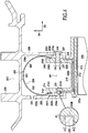
- the figure 1 shows a high pressure turbine ring assembly comprising a turbine ring 1 made of a ceramic matrix composite material (CMC) and a ring support metal structure 3.
- the turbine ring 1 surrounds a set of rotary blades 5.
- the turbine ring 1 is formed of a plurality of ring sectors 10, the figure 1 being a radial section view.
- the arrow DA indicates the axial direction with respect to the turbine ring 1 while the arrow DR indicates the radial direction with respect to the turbine ring 1.
- Each ring sector 10 has a substantially P-shaped or inverted ⁇ -shaped section with an annular base 12 whose inner face coated with a layer 13 of abradable material defines the flow stream gas flow in the turbine.
- Upstream and downstream tabs 14, 16 extend from the outer face of the annular base 12 in the radial direction DR.
- upstream and downstream are used herein with reference to the flow direction of the gas flow in the turbine (arrow F).
- the ring support structure 3 which is integral with a turbine casing 30 comprises an element or elastic holding means 50 comprising a base 51 fixed on the inner face of the shell 31 of the turbine casing 30, a first and a second arm 52 and 53 extend from the base 51 respectively upstream and downstream.
- the base 51 can be fixed on the inner face of the ferrule 31 of the turbine casing 30, in particular by welding, by plating, by riveting or by clamping by means of a screw / nut-type connection member, the orifices being pierced in the base 51 and the ferrule 31 to allow the passage of the fastening or connecting elements.
- the first arm 52 comprises at its free end 520 an elastic fastening portion 521 C-clip type here having a radius of curvature.
- the elastic fastening portion 521 holds the free end 141 of the upstream tab 14 of each ring sector 10.
- the free end 141 of the upstream tab 14 has internal grooves 142 and 143 external grooves formed on each side of the lug 14 and cooperating with the elastic fastening portion 521, the grooves 142 and 143 having here a radius of curvature similar to the radius of curvature of the elastic fastening portion 521.
- the second arm 53 comprises at its free end 530 an elastic fastening portion 531 type C-clip, here having a radius curvature, which holds the free end 161 of the downstream tab 16 of each ring sector 10.
- the free end 161 of the downstream tab 16 has internal grooves 162 and outer 163 formed on each side of the tab 16 and cooperating with the elastic fastening portion 531, the grooves 162 and 163 having here a radius of curvature similar to the radius of curvature of the elastic fastening portion 531.
- the elastic holding member 50 may be made of a metallic material such as a Waspaloy®, inconel 718 or AM1 alloy. It is preferably made of several annular sectors in order to facilitate its fixing on the housing 30.
- the elastic holding element 50 ensures the cold maintenance of the ring sectors 10 on the ring support structure 3.
- the temperature at which the ring assembly is located when the turbine does not operate that is to say at an ambient temperature which may be for example about 25 ° C.
- the ring support structure 3 comprises an annular upstream radial flange 32 having a first projection 34 on its inner face 32a opposite the upstream tabs 14 of the ring sectors 10, the projection 34 being housed in an annular groove 140 present on the outer face 14a of the upstream lugs 14.
- a clearance J1 is present cold between the first projection 34 and the annular groove 140.
- the expansion of the first projection 34 in the annular groove 140 contributes to the hot maintenance of the ring sectors 10 on the ring support structure 3.
- hot is meant here the temperatures to which the ring assembly is subjected during the operation of the turbine, these temperatures being between 600 ° C and 900 ° C .
- the annular upstream radial flange 32 also has a second projection 35 facing the outer face 14a of the upstream lugs 14, the second projection 35 extending from the inner face 32a of the upstream radial flange 32 for a distance less than that of the first projection 34.
- the ring support structure On the downstream side, the ring support structure comprises an annular downstream radial flange 36 having a projection 38 on its inner face 36a opposite the downstream tabs 16 of the ring sectors 10.
- each fret 40 passes through respectively an orifice 37 formed in the annular downstream radial flange 36 and an orifice 17 formed each downstream lug 16, the orifices 37 and 17 being aligned during the assembly of the ring sectors 10 on the ring support structure 3.
- the locking bands 40 are made of a material having a coefficient of thermal expansion greater than the coefficient of thermal expansion of the ceramic matrix composite material of the ring sectors 10.
- the locking bands 40 may for example be made of metal material.
- a clearance J2 is present cold between the locking frets 40 and the orifices 17 present in each downstream lug 16. The expansion of the locking frets 40 in the orifices 17 contributes to the hot maintenance of the ring sectors 10 on the structure of ring support 3.
- inter-sector sealing is provided by sealing tabs housed in grooves facing in the opposite edges of two neighboring ring sectors.
- a tongue 22a extends over almost the entire length of the annular base 12 in the middle portion thereof.
- Another tab 22b extends along the tab 14 and on a portion of the annular base 12.
- Another tab 22c extends along the tab 16. At one end, the tab 22c abuts the tab 22a and on the tongue 22b.
- the tongues 22a, 22b, 22c are for example metallic and are mounted with cold play in their housings to ensure the sealing function at the temperatures encountered in service.
- Ventperes 33 formed in the flange 32 make it possible to supply cooling air to the outside of the turbine ring 10.
- Each ring sector 10 described above is made of ceramic matrix composite material (CMC) by forming a fibrous preform having a shape close to that of the ring sector and densification of the ring sector by a ceramic matrix .
- CMC ceramic matrix composite material
- ceramic fiber yarns for example SiC fiber yarns, such as those marketed by the Japanese company Nippon Carbon under the name "Nicalon”, or carbon fiber yarns.
- the fiber preform is advantageously made by three-dimensional weaving, or multilayer weaving with development of debonding zones to separate the preform portions corresponding to the tabs 14 and 16 of the sectors 10.
- the weave can be interlock type, as illustrated.
- Other weaves of three-dimensional weave or multilayer can be used as for example multi-web or multi-satin weaves.
- the blank After weaving, the blank can be shaped to obtain a ring sector preform which is consolidated and densified by a ceramic matrix, the densification can be achieved in particular by chemical vapor infiltration (CVI) which is well known in itself.
- CVI chemical vapor infiltration
- the ring support structure 3 is made of a metallic material such as a Waspaloy®, inconel 718 or AM1 alloy.
- the ring support structure comprises at least one flange.
- the annular downstream radial flange 36 which is elastically deformable in the axial direction DA of the ring.
- the annular downstream radial flange 36 is pulled in the direction DA as shown in FIG. figure 2 in order to increase the spacing between the flanges 32 and 36 and to allow the insertion of the first projection 34 present on the flange 32 in the groove 140 present on the lug 14 without risk of damaging the ring sector 10.
- the traction in the axial direction DA of the ring exerted on the elastically deformable flange 36 is here carried out by means of a tool 50 comprising at least one arm 51 whose end comprises a hook 510 which is engaged in a hook 39 present on the outer face 36a of the flange 36.
- the number of hooks 39 distributed on the face 36a of the flange 36 is defined as a function of the number of traction points that one This number depends mainly on the elastic nature of the flange.
- Other forms and arrangements of means for exerting traction in the axial direction DA on one of the flanges of the ring support structure can of course be considered within the scope of the present invention.
- the free ends 141 and 161 of the lugs 14 and 16 are respectively engaged in the elastic attachment portions 521 and 531 of the elastic holding element 50, on the one hand, until the grooves 142 and 143 of the lug 14 respectively cooperate with the curved ends 5210 and 5211 of the elastic fastening portion 521, and, on the other hand, until the grooves 162 and 163 of the lug 16 cooperate respectively with the curved ends 5310 and 5311 of the elastic attachment portion 531.
- each lug 14 or 16 of the ring sector may comprise one or more orifices for the passage of one or more frets.
- the hoop 40 are hooped in the orifices 37 of the annular downstream radial flange 36 by known metal assemblies such as adjustments H6-P6 or other force arrangements that allow the holding of these elements cold.
- the frets 40 may be replaced by pins or any other equivalent element.
- the ring sectors 10 are held by the elastic holding element 50.
- the expansion of the elastic holding element 50 no longer makes it possible to maintain the ring sectors at the level of the portions. fastening 521 and 531.
- the hot keeping is provided both by the expansion of the protrusion 34 in the groove 140 of the lug 14 which fills or cancels the clearance J1 and by the expansion of the hoop 40 in the orifice 17 of the tab 16 which fills or cancels the game J2.
- the figure 3 shows an alternative embodiment of the high pressure turbine ring assembly which differs from the high pressure turbine ring assembly described above in connection with the figures 1 and 2 in that the internal and external grooves 1142, 1143 present at the end 1141 of the tab 114 of the ring sectors 110 and the internal and external grooves 1162, 1163 present at the end 1161 of the tab 116 of the sectors of 110 have a rectilinear shape and that the curved ends 6210, 6211 of the elastic fastening portion 621 has the end of the first arm 62 of the elastic holding member 60 and the curved ends 6310, 6311 of the elastic fastening portion 631 at the end of the second arm 63 of the elastic holding member 60 extend in a rectilinear direction.
- the elastic holding member 60 is made of a plurality of segments.
- the other parts of the high pressure turbine ring assembly are identical to those already described above in connection with the ring assembly shown in the drawings. figures 1 and 2 .
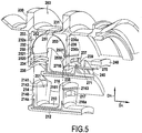
- the figure 4 shows a set of high pressure turbine ring according to another embodiment which differs from the above described ring assembly in connection with the figures 1 and 2 in that it uses a different elastic holding means or element.
- the ring set of the figure 4 comprises a turbine ring 201 of ceramic matrix composite material (CMC) and a ring support metal structure 203.
- the turbine ring 201 is formed of a plurality of ring sectors 210 and surrounds a set of blades 205.
- Each ring sector 210 has a substantially P-shaped or inverted ⁇ -shaped section with an annular base 212 whose inner face is coated with a layer 213 of abradable material, upstream and downstream legs 214, 216 extend from the outer face of the annular base 212 in the radial direction DR.
- the ring support structure 203 which is integral with a turbine casing 230 comprises an element or elastic holding means 250 comprising a base 251 fixed on the inner face of the shell 231 of the turbine casing 230, a first and a second arm 252 and 253 extend from the base 251 respectively upstream and downstream.
- the elastic holding element 250 forms with these two arms 252 and 253 a C-clip type elastic fastener making it possible to keep the ring sectors 210 cold on the ring support structure 203.
- the first arm 252 comprises its free end 2520 a curved attachment portion 2521 extending here in a rectilinear direction.
- the curved attachment portion 2521 holds the free end 2141 of the upstream tab 214 of each ring sector 210.
- the free end 2141 of the upstream tab 214 has an external groove 2143 formed on the outer face 214a of the tab 214 and cooperating with the curved attachment portion 2521, the groove 2143 here having a rectilinear shape.
- the second arm 253 comprises at its free end 2530 a curved attachment portion 2531, extending in a rectilinear direction, which holds the free end 2161 of the downstream tab 216 of each ring sector 210.
- free end 2161 of the downstream tab 216 has an external groove 2163 formed on the outer face 216a of the tab 216 and cooperating with the curved attachment portion 2531, the groove 2163 here having a rectilinear shape.
- the elastic holding member 250 may be made of metallic material such as a Waspaloy® alloy, inconel 718, or AM1. It is preferably made of several annular sectors to facilitate its attachment to the housing 230. The elastic holding member 250 ensures the cold maintenance of the ring sectors 210 on the ring support structure 203.
- the ring support structure 203 comprises an annular upstream radial flange 232 having a first projection 234 on its inner face 232a opposite the upstream tabs 214 of the ring sectors 210, the projection 234 being housed in an annular groove 2140 present on the outer face 214a of the upstream legs 214.
- a clearance J21 is present cold between the first projection 234 and the annular groove 2140. The expansion of the first projection 234 in the annular grooves 2140 participates in the hot maintenance of the ring sectors 210 on the ring support structure 203.
- the annular upstream radial flange 232 also has a second projection 235 opposite the outer face 214a of the upstream tabs 214, the second projection 235 extending from the inner face 232a of the upstream radial flange 232 to a distance less than that of the first projection 234.
- the ring support structure comprises an annular downstream radial flange 236 having a projection 238 on its inner face 236a opposite the legs downstream 216 ring sectors 210.
- the ring sectors 210 are furthermore held by holding elements, here in the form of locking frets 240.
- the locking frets 240 are engaged both in the upstream downstream flange. annular 236 of the ring support structure 203 and in the downstream legs 216 of the ring sectors 210.
- each band 240 passes respectively through an orifice 237 formed in the annular downstream radial flange 236 and an orifice 217 formed each
- the blocking shrouds 240 are made of a material having a coefficient of thermal expansion greater than the coefficient of thermal expansion of the ceramic matrix composite material of the ring sectors 210.
- the blocking frets 240 may for example be made of metallic material.
- a clearance J22 is present in cold condition between the locking frets 240 and the orifices 217 present in each downstream lug 216.
- the expansion of the locking frets 240 in the orifices 217 contributes to the heat retention of the ring sectors 210 on the structure of ring support 203.
- inter-sector sealing is provided by sealing tabs 222a, 222b, 222c as previously described.
- ventilation orifices 233 formed in the flange 232 make it possible to supply cooling air to the outside of the turbine ring 210.
- Each ring sector 210 is made of ceramic matrix composite material (CMC) by forming a fibrous preform having a shape close to that of the ring sector and densifying the ring sector by a ceramic matrix.
- the ring support structure 203 is made of a metallic material such as a Waspaloy®, inconel 718 or AM1 alloy.
- the annular downstream radial flange 236 When mounting a ring sector 210, the annular downstream radial flange 236 is pulled in the direction DA as shown in FIG. figure 5 to allow the insertion of the first projection 234 present on the flange 232 in the groove 2140 present on the leg 214 without risk in order to facilitate the traction separation of the annular downstream radial flange 236, the latter comprises a plurality of hooks 239 distributed on its face 236b, which face is opposite the face 236a of the flange 236 opposite the downstream tabs 216 of the ring sectors 210.
- the traction in the axial direction DA of the ring exerted on the elastically deformable flange 236 is here carried out by means of a tool 270 comprising at least one arm 271 whose end comprises a hook 2710 which is engaged in a hook 239 present on the outer face 236a of the flange 236.
- the free ends 2141 and 2161 of the tabs 214 and 216 are engaged between the ends 2520 and 2530 of the elastic holding member 250 until the groove 2143 of the leg 214 and the groove 2163 of the tab 216 cooperate respectively with the curved attachment portions 2521 and 2531 of the elastic holding member 250.
- the projection 234 of the flange 214 inserted in the groove 2140 of the tab 214 the Curved attachment portions 2521 and 2531 positioned in the grooves 2143 and 2163 and said tabs 214 and 216 positioned to align the holes 217 and 237, the flange 236 is released.
- a band 240 is then engaged in the aligned orifices 237 and 217 respectively formed in the annular downstream radial flange 236 and in the downstream tab 216.
- Each leg 214 or 216 ring sector may comprise one or more orifices for the passage of one or more frets.
- the frets 240 are shrunk in the orifices 237 of the annular downstream radial flange 236 by known metal assemblies such as adjustments H6-P6 or other force arrangements that allow the holding of these elements cold.
- the frets 240 may be replaced by pins or any other equivalent element.
- the ring sectors 210 are held by the elastic holding element 250.
- the expansion of the elastic holding element 250 no longer makes it possible to maintain the ring sectors at the level of the portions. Curved fasteners 2521 and 2531.
- the hot hold is provided both by the expansion of the projection 234 in the groove 2140 of the tab 214 which fills or cancels the clearance J21 and by the expansion of the band 240 in the orifice 217 of the tab 16 which fills or cancels the game J22.
- the figure 6 shows a high pressure turbine ring assembly according to another embodiment.
- the ring set of the figure 6 comprises a turbine ring 301 made of a ceramic matrix composite material (CMC) and a ring support metal structure 303 integral with a turbine casing 330.
- the turbine ring 301 is formed of a plurality of sectors of ring 310 and surrounds a set of rotating blades (not shown on the figure 6 ).
- Each ring sector 310 has a K-shape with an annular base 312 whose inner face coated with a layer 313 of abradable material defines the flow stream gas flow in the turbine.
- a first leg 314 and a second substantially S-shaped lug 316 extend from the outer face of the annular base 312.
- the ring support structure 303 comprises an annular upstream radial flange 332 having a first projection 334 on its inner face 332a opposite the upstream tabs 314 of the ring sectors 310, the projection 334 being housed in an annular groove 3140 present in FIG. the end 3141 of the upstream tabs 314.
- a clearance J31 is present cold between the first projection 334 and the annular groove 3140.
- the expansion of the first projection 334 in the annular grooves 3140 contributes to the hot maintenance of the ring sectors 310 on the ring support structure 303.
- the annular upstream radial flange 332 also has a second projection 335 which extends under the end 3141 of the upstream tabs 314.
- the ring support structure On the downstream side, the ring support structure comprises an annular downstream radial flange 336 having a projection 338 on its outer face 336b.
- the annular radial flange 336 further comprises arms 339, here two in each ring sector, which extend radially on the side of the outer surface of the flange 336.
- Each arm 339 has at its free end 3390 an orifice 3391.
- the ring assembly further comprises elastic holding means or members 350 of the C-clip type each comprising a first elastic attachment portion 352 and a second elastic attachment portion 353.
- the elastic holding members 350 make it possible to cold keeping the end 3161 of the downstream lug 316 of the ring sectors 310 against the seam 338, a constraint being exerted on its two parts respectively by the end 3520 of the first elastic fastening portion 352 and the end 3530 of the second elastic fastening portion 353 of each elastic holding member 350.
- the elastic holding member 350 may be made of metal material such as a Waspaloy® alloy, inconel 718, or AM1.
- the ring sectors 310 are further maintained by holding members, here in the form of pins 340.
- the pins 340 are engaged both in the arms 339 of the annular upstream downstream flange. 336 of the ring support structure 303, in the elastic retaining elements 350 and in the downstream tabs 316 of the ring sectors 310.
- each pin 340 passes through respectively an orifice 3391 formed in each arm 339 present on the annular downstream radial flange 3236, an orifice 355 formed in each elastic holding element 350 and an orifice 317 formed in each lug 316.
- the pins 340 are made of a material having a coefficient of thermal expansion greater than the coefficient of thermal expansion of the material ceramic matrix composite of the ring sectors 310.
- the pins 340 may for example be made of metal material.
- a clearance J32 is present cold between the pins 340 and the orifices 317 present in each downstream leg 216. The expansion of the pins 340 in the orifices 317 participate in the hot maintenance of the ring sectors 310 on the ring support structure 303.
- Each ring sector 310 is made of ceramic matrix composite material (CMC) by forming a fibrous preform having a shape close to that of the ring sector and densification of the ring sector by a ceramic matrix.
- the ring support structure 303 is made of a metallic material such as a Waspaloy®, inconel 718 or AM1 alloy.
- the first projection 334 present on the flange 332 is engaged in the groove 3140 on the tab 314.
- the end 3161 of the tab 316 of each ring sector 310 is pressed against the projection 338 at the end of the Annular flange 336.
- the elastic fastening elements 250 are positioned between the end 3161 and the projection 338, the end 3520 of the first portion resilient fastener 352 being in contact with the protrusion 338 and the end 3530 of the second elastic fastening portion 353 of each elastic holding member 350 being in contact with the end 3161 of the tab 316.
- the elastic members 350 keep the end 3161 of the lug 316 of each ring sector 310 against the seam 338 of the annular flange 336 cold.
- a pin 340 is then engaged in each series of aligned orifices 3391, 355, and 317 respectively formed in each arm 339 present on the annular downstream radial flange 3236, in an elastic holding member 350 and in the leg 316.
- the pins 340 are shrunk into the orifices 3391 of each arm 339 by known metal assemblies such as adjustments H6-P6 or other strength arrangements that allow the holding of these elements cold.
- the pins 340 may be replaced by fretsou any other equivalent element.
- the ring sectors 310 are held by the resilient retaining element 350.
- the expansion of the elastic retaining element 350 no longer makes it possible to maintain the ring sectors at the level of the portions. resilient fasteners 352 and 353.
- the hot hold is provided both by the expansion of the protrusion 334 in the groove 3140 of the tab 314 which fills or cancels the clearance J31 and by the expansion of the pins 340 in the orifice 317 of the paw 316 which fills or cancels the game J32.
- the turbine ring assembly of the figures 6 and 7 has been described with ring sectors having a K-shaped cross-section. However, this embodiment also applies to ring sectors having a substantially inverted ⁇ -shaped cross-section like those shown on FIG. Figures 1 to 5 . Likewise, the embodiments of the turbine ring assembly described in connection with the Figures 1 to 5 also apply to ring sectors having a K-shaped section.
Description
Le domaine d'application de l'invention est notamment celui des moteurs aéronautiques à turbine à gaz. L'invention est toutefois applicable à d'autres turbomachines, par exemple des turbines industrielles.The field of application of the invention is in particular that of aeronautical gas turbine engines. The invention is however applicable to other turbomachines, for example industrial turbines.
Les matériaux composites à matrice céramique, ou CMC, sont connus pour conserver leurs propriétés mécaniques à des températures élevées, ce qui les rend aptes à constituer des éléments de structure chaude.Ceramic matrix composite materials, or CMCs, are known to retain their mechanical properties at high temperatures, which makes them suitable for constituting hot structural elements.
Dans des moteurs aéronautiques à turbine à gaz, l'amélioration du rendement et la réduction de certaines émissions polluantes conduisent à rechercher un fonctionnement à des températures toujours plus élevées. Dans le cas d'ensembles d'anneau de turbine entièrement métalliques, il est nécessaire de refroidir tous les éléments de l'ensemble et en particulier l'anneau de turbine qui est soumis à des flux très chauds, typiquement supérieurs à la température supportable par le matériau métallique. Ce refroidissement a un impact significatif sur la performance du moteur puisque le flux de refroidissement utilisé est prélevé sur le flux principal du moteur. En outre, l'utilisation de métal pour l'anneau de turbine limite les possibilités d'augmenter la température au niveau de la turbine, ce qui permettrait pourtant d'améliorer les performances des moteurs aéronautiques.In aeronautical gas turbine engines, improving efficiency and reducing certain pollutant emissions lead to the search for operation at ever higher temperatures. In the case of all-metal turbine ring assemblies, it is necessary to cool all the elements of the assembly and in particular the turbine ring which is subjected to very hot flows, typically higher than the temperature bearable by the metallic material. This cooling has a significant impact on the engine performance since the cooling flow used is taken from the main flow of the engine. In addition, the use of metal for the turbine ring limits the possibilities of increasing the temperature at the turbine, which would however improve the performance of aircraft engines.
Par ailleurs, un ensemble d'anneau de turbine métallique se déforme sous l'effet des flux thermiques, ce qui modifie les jeux au niveau de la veine d'écoulement et, par conséquent, les performances de la turbine.Furthermore, a set of metal turbine ring deforms under the effect of heat flow, which changes the clearance at the flow path and, therefore, the performance of the turbine.
C'est pourquoi l'utilisation de CMC pour différentes parties chaudes des moteurs a déjà été envisagée, d'autant que les CMC présentent comme avantage complémentaire une masse volumique inférieure à celle de métaux réfractaires traditionnellement utilisés.This is why the use of CMC for different hot parts of the engines has already been considered, especially since CMCs have the additional advantage of lower density than refractory metals traditionally used.
Ainsi, la réalisation de secteurs d'anneau de turbine en une seule pièce en CMC est notamment décrite dans le document
L'utilisation de secteurs d'anneau en CMC permet de réduire significativement la ventilation nécessaire au refroidissement de l'anneau de turbine. Toutefois, le maintien en position des secteurs d'anneau demeure un problème en particulier vis-à-vis des dilatations différentielles qui peuvent se produire entre la structure métallique de support et les secteurs d'anneau en CMC. En outre, une autre problématique réside dans le contrôle de la forme de la veine aussi bien à froid qu'à chaud sans générer de contraintes trop importantes sur les secteurs d'anneau.The use of ring segments in CMC significantly reduces the ventilation required to cool the turbine ring. However, maintaining the ring sectors in position remains a problem in particular with respect to the differential expansions that can occur between the metal support structure and the CMC ring sectors. In addition, another problem lies in controlling the shape of the vein both cold and hot without generating too much stress on the ring sectors.
L'invention vise à éviter de tels inconvénients et propose à cet effet un ensemble d'anneau de turbine comprenant une pluralité de secteurs d'anneau en matériau composite à matrice céramique formant un anneau de turbine et une structure de support d'anneau comportant une première et une deuxième brides annulaires, chaque secteur d'anneau ayant une partie formant base annulaire avec une face interne définissant la face interne de l'anneau de turbine et une face externe à partir de laquelle s'étendent une première et une deuxième pattes, les pattes de chaque secteur d'anneau étant maintenues entre les deux brides annulaires de la structure de support d'anneau, caractérisé en ce que la première patte de chaque secteur d'anneau comporte une rainure annulaire sur sa face en regard de la première bride annulaire de la structure de support d'anneau, la première bride annulaire de la structure de support d'anneau comprenant une saillie annulaire sur sa face en regard de la première patte de chaque secteur d'anneau, la saillie annulaire de la première bride étant logée dans la rainure annulaire de la première patte de chaque secteur d'anneau, un jeu étant présent à froid entre la saillie annulaire et la rainure annulaire, en ce qu'au moins la deuxième patte de chaque secteur d'anneau est reliée à la structure de support d'anneau par au moins un élément de maintien élastique, et en ce que la deuxième patte de chaque secteur d'anneau comporte au moins une ouverture dans laquelle est logée une partie d'un élément de maintien solidaire de la deuxième bride annulaire de la structure de support d'anneau, un jeu étant présent à froid entre l'ouverture de la deuxième patte et la partie de l'élément de maintien présente dans ladite ouverture, ledit élément de maintien étant en un matériau ayant un coefficient de dilatation thermique supérieur au coefficient de dilatation thermique du matériau composite à matrice céramique des secteurs d'anneau.The aim of the invention is to avoid such drawbacks and proposes for this purpose a turbine ring assembly comprising a plurality of ring sectors of ceramic matrix composite material forming a turbine ring and a ring support structure comprising a first and second annular flanges, each ring sector having an annular base portion with an inner face defining the inner face of the turbine ring and an outer face from which a first and a second leg extend, the tabs of each ring sector being held between the two annular flanges of the ring support structure, characterized in that the first tab of each ring sector has an annular groove on its face opposite the first flange. of the ring support structure, the first annular flange of the ring support structure comprising an annular projection on its face opposite the first leg of each ring sector, the annular projection of the first flange being housed in the annular groove of the first leg of each ring sector, a clearance being present cold between the annular projection and the annular groove, in that at least the second leg of each ring sector is connected to the ring support structure by at least one elastic holding member, and in that the second leg of each ring sector has at least one opening in which is housed a portion of a holding member secured to the second annular flange of the ring support structure, a game being present cold between the opening of the second tab and the portion of the holding member in said opening, said holding member being of a material having a thermal expansion coefficient greater than the thermal expansion coefficient of the ceramic matrix composite material of the ring sectors.
Dans l'ensemble d'anneau selon l'invention, les secteurs d'anneau sont maintenus à froid par des moyens de maintien élastiques qui permettent un montage des secteurs d'anneau sans précontrainte. Le maintien des secteurs d'anneau par les moyens de maintien élastiques n'est plus assuré à chaud en raison de leur dilatation. A chaud, l'effort de maintien est repris par la dilatation de la saillie annulaire de la première bride et le ou les éléments de maintien, dilatation qui n'entraîne pas de contrainte sur les secteurs d'anneaux en raison de la présence d'un jeu à froid entre la saillie annulaire de la première bride et la rainure annulaire de la première patte de chaque secteur d'anneau, d'une part, et, d'autre part, le jeu présent entre le ou les éléments de maintien et la ou les ouvertures de la deuxième patte.In the ring assembly according to the invention, the ring sectors are kept cold by elastic holding means which allow mounting of the ring sectors without prestressing. The maintenance of the ring sectors by the elastic holding means is no longer ensured hot because of their expansion. When hot, the holding force is resumed by the expansion of the annular projection of the first flange and the holding element or elements, which expansion does not cause stress on the ring sectors due to the presence of a cold clearance between the annular projection of the first flange and the annular groove of the first leg of each ring sector, on the one hand, and, on the other hand, the clearance present between the holding element (s) and the opening or openings of the second leg.
Selon un mode de réalisation de l'ensemble d'anneau selon l'invention, chaque secteur d'anneau présente une forme de Pi en coupe axiale, des première et deuxième pattes s'étendant à partir de la face externe de la partie formant base annulaire, le moyen de maintien élastique comprenant une base fixée sur la structure de support d'anneau à partir de laquelle s'étendent un premier et un deuxième bras, chaque bras comportant à son extrémité libre une portion d'attache élastique de type C-clip, l'extrémité libre de la première patte de chaque secteur d'anneau étant maintenue par la portion d'attache élastique du premier bras tandis que l'extrémité libre de la deuxième patte de chaque secteur d'anneau est maintenue par la portion d'attache élastique du deuxième bras du moyen de maintien élastique.According to one embodiment of the ring assembly according to the invention, each ring sector has a Pi shape in axial section, first and second legs extending from the outer face of the base portion. annular, the elastic holding means comprising a base fixed on the ring support structure from which extend a first and a second arm, each arm having at its free end a resilient attachment portion of type C- clip, the free end of the first leg of each ring sector being held by the elastic attachment portion of the first arm while the free end of the second leg of each ring sector is maintained by the portion of elastic fastening of the second arm of the elastic holding means.
L'utilisation de portions d'attache élastiques de type C-clip permet un montage à froid avec des contraintes limitées. Le contact entre les secteurs d'anneau et la structure de support d'anneau est uniforme, ce qui permet une bonne répartition des efforts.The use of C-clip elastic attachment portions allows cold mounting with limited constraints. The contact between the ring sectors and the ring support structure is uniform, which allows a good distribution of forces.
Selon une caractéristique particulière de l'ensemble d'anneau de l'invention, la première patte de chaque secteur d'anneau comporte une rainure externe et une rainure interne coopérant avec la portion d'attache élastique de type C-clip du premier bras du moyen de maintien élastique, la deuxième patte de chaque secteur d'anneau comportant une rainure externe et une rainure interne coopérant avec la portion d'attache élastique de type C-clip du deuxième bras du moyen de maintien élastique.According to a particular characteristic of the ring assembly of the invention, the first leg of each ring sector has an external groove and an internal groove cooperating with the C-clip type elastic attachment portion of the first arm of the ring. holding means elastic, the second leg of each ring sector having an outer groove and an inner groove cooperating with the C-clip type elastic fastening portion of the second arm of the elastic holding means.
Les rainures internes et externes des première et deuxième pattes de chaque secteur d'anneau peuvent présenter un rayon de courbure similaire au rayon de courbure des portions d'attache élastiques de type C-clip des premier et deuxième bras du moyen de maintien élastique. Elles peuvent également présenter une forme rectiligne, les portions d'attache élastiques de type C-clip des premier et deuxième bras du moyen de maintien élastique s'étendant dans ce cas suivant une direction rectiligne.The internal and external grooves of the first and second legs of each ring sector may have a radius of curvature similar to the radius of curvature of the C-clip type elastic attachment portions of the first and second arms of the elastic holding means. They may also have a rectilinear shape, the C-clip type elastic attachment portions of the first and second arms of the elastic holding means extending in this case in a rectilinear direction.
Selon un autre mode de réalisation de l'ensemble d'anneau selon l'invention, chaque secteur d'anneau présente une forme de Pi en coupe axiale, des première et deuxième pattes s'étendant à partir de la face externe de la partie formant base annulaire, le moyen de maintien élastique comprenant une base fixée sur la structure de support d'anneau à partir de laquelle s'étendent un premier et un deuxième bras formant ensemble une portion d'attache élastique de type C-clip, l'extrémité libre de la première patte de chaque secteur d'anneau étant maintenue par le premier bras tandis que l'extrémité libre de la deuxième patte de chaque secteur d'anneau est maintenue par le deuxième bras du moyen de maintien élastique.According to another embodiment of the ring assembly according to the invention, each ring sector has a Pi shape in axial section, first and second legs extending from the outer face of the portion forming annular base, the elastic holding means comprising a base attached to the ring support structure from which extend a first and a second arm together forming a C-clip elastic fastening portion, the end free of the first leg of each ring sector being held by the first arm while the free end of the second leg of each ring sector is held by the second arm of the elastic holding means.
L'utilisation d'une portion d'attache élastique de type C-clip permet un montage à froid avec des contraintes limitées. Le contact entre les secteurs d'anneau et la structure de support d'anneau est uniforme, ce qui permet une bonne répartition des efforts.The use of a C-clip elastic attachment portion allows cold mounting with limited constraints. The contact between the ring sectors and the ring support structure is uniform, which allows a good distribution of forces.
Selon une caractéristique particulière de l'ensemble d'anneau de l'invention, la première patte de chaque secteur d'anneau comporte une rainure externe coopérant avec l'extrémité libre du premier bras du moyen de maintien élastique, la deuxième patte de chaque secteur d'anneau comportant une rainure externe coopérant avec l'extrémité libre du deuxième bras du moyen de maintien élastique.According to a particular feature of the ring assembly of the invention, the first leg of each ring sector has an external groove cooperating with the free end of the first arm of the elastic holding means, the second leg of each sector. ring having an external groove cooperating with the free end of the second arm of the elastic holding means.
Les rainures externes des première et deuxième pattes de chaque secteur d'anneau peuvent présenter une forme rectiligne, les extrémités libres des premier et deuxième bras du moyen de maintien élastique s'étendant suivant une direction rectiligne.The outer grooves of the first and second legs of each ring sector may have a rectilinear shape, the free ends of the first and second arms of the elastic holding means extending in a rectilinear direction.
Selon encore un autre mode de réalisation de l'ensemble d'anneau selon l'invention, chaque secteur d'anneau présente en coupe axiale une forme de K, des première et deuxième pattes s'étendant à partir de la face externe de la partie formant base annulaire, la première patte comportant à son extrémité une rainure annulaire dans laquelle est logée la saillie annulaire de la première bride annulaire, la deuxième patte de chaque secteur d'anneau étant reliée à la deuxième bride par un ou plusieurs éléments de maintien élastiques.According to yet another embodiment of the ring assembly according to the invention, each ring sector presents in axial section a K-shape, first and second legs extending from the outer face of the part. forming an annular base, the first tab having at its end an annular groove in which is housed the annular projection of the first annular flange, the second leg of each ring sector being connected to the second flange by one or more elastic holding elements .
Selon une caractéristique particulière de l'ensemble d'anneau de l'invention, la deuxième patte de chaque secteur d'anneau est reliée à la deuxième bride annulaire de la structure de support d'anneau par un ou plusieurs éléments de clipsage.According to a particular feature of the ring assembly of the invention, the second leg of each ring sector is connected to the second annular flange of the ring support structure by one or more clipping members.
L'invention sera mieux comprise à la lecture faite ci-après, à titre indicatif mais non limitatif, en référence aux dessins annexés sur lesquels :
- la
figure 1 est une vue en section montrant un mode de réalisation d'un ensemble d'anneau de turbine selon l'invention ; - la
figure 2 montre schématiquement le montage d'un secteur d'anneau dans la structure de support d'anneau de l'ensemble d'anneau de lafigure 1 ; - la
figure 3 est une vue schématique en perspective montrant une variante de réalisation de l'ensemble d'anneau de lafigure 1 ; - la
figure 4 est une vue en section montrant un autre mode de réalisation d'un ensemble d'anneau de turbine selon l'invention ; - la
figure 5 montre schématiquement le montage d'un secteur d'anneau dans la structure de support d'anneau de l'ensemble d'anneau de lafigure 4 ; - la
figure 6 est une vue en section montrant un autre mode de réalisation d'un ensemble d'anneau de turbine selon l'invention ; - la
figure 7 montre schématiquement le montage d'un secteur d'anneau dans la structure de support d'anneau de l'ensemble d'anneau de lafigure 6 .
- the
figure 1 is a sectional view showing an embodiment of a turbine ring assembly according to the invention; - the
figure 2 schematically shows the mounting of a ring sector in the ring support structure of the ring assembly of thefigure 1 ; - the
figure 3 is a schematic perspective view showing an alternative embodiment of the ring assembly of thefigure 1 ; - the
figure 4 is a sectional view showing another embodiment of a turbine ring assembly according to the invention; - the
figure 5 schematically shows the mounting of a ring sector in the ring support structure of the ring assembly of thefigure 4 ; - the
figure 6 is a sectional view showing another embodiment of a turbine ring assembly according to the invention; - the
figure 7 schematically shows the mounting of a ring sector in the ring support structure of the ring assembly of thefigure 6 .
La
Chaque secteur d'anneau 10 a une section sensiblement en forme de Pi ou π inversé avec une base annulaire 12 dont la face interne revêtue d'une couche 13 de matériau abradable définit la veine d'écoulement de flux gazeux dans la turbine. Des pattes amont et aval 14, 16 s'étendent à partir de la face externe de la base annulaire 12 dans la direction radiale DR. Les termes "amont" et "aval" sont utilisés ici en référence au sens d'écoulement du flux gazeux dans la turbine (flèche F).Each
La structure de support d'anneau 3 qui est solidaire d'un carter de turbine 30 comprend un élément ou moyen de maintien élastique 50 comprenant une base 51 fixée sur la face interne de la virole 31 du carter de turbine 30, un premier et un deuxième bras 52 et 53 s'étendent depuis la base 51 respectivement vers l'amont et l'aval. La base 51 peut être fixé sur la face interne de la virole 31 du carter de turbine 30 notamment par soudage, par piontage, par rivetage ou par serrage au moyen d'organe de liaisons de type vis/écrou, des orifices étant percés dans la base 51 et la virole 31 pour permettre le passage des éléments de fixation ou de liaison.The
Le premier bras 52 comprend à son extrémité libre 520 une portion d'attache élastique 521 de type C-clip présentant ici un rayon de courbure. La portion d'attache élastique 521 maintien l'extrémité libre 141 de la patte amont 14 de chaque secteur d'anneau 10. L'extrémité libre 141 de la patte amont 14 comporte des rainures interne 142 et externe 143 ménagées de chaque côté de la patte 14 et coopérant avec la portion d'attache élastique 521, les rainures 142 et 143 présentant ici un rayon de courbure similaire au rayon de courbure de la portion d'attache élastique 521. De même, le deuxième bras 53 comprend à son extrémité libre 530 une portion d'attache élastique 531 de type C-clip, présentant ici un rayon de courbure, qui maintien l'extrémité libre 161 de la patte aval 16 de chaque secteur d'anneau 10. L'extrémité libre 161 de la patte aval 16 comporte des rainures interne 162 et externe 163 ménagées de chaque côté de la patte 16 et coopérant avec la portion d'attache élastique 531, les rainures 162 et 163 présentant ici un rayon de courbure similaire au rayon de courbure de la portion d'attache élastique 531.The
L'élément de maintien élastique 50 peut être réalisé en matériau métallique tel qu'un alliage Waspaloy®, inconel 718, ou AM1. Il est de préférence réalisé en plusieurs secteurs annulaires afin de faciliter sa fixation sur le carter 30. L'élément de maintien élastique 50 assure le maintien à froid des secteurs d'anneau 10 sur la structure de support d'anneau 3. Par « à froid », on entend dans la présente invention, la température à laquelle se trouve l'ensemble d'anneau lorsque la turbine ne fonctionne pas, c'est-à-dire à une température ambiante qui peut être par exemple d'environ 25°C.The elastic holding
La structure de support d'anneau 3 comprend une bride radiale amont annulaire 32 comportant une première saillie 34 sur sa face interne 32a en regard des pattes amont 14 des secteurs d'anneau 10, la saillie 34 étant logée dans une rainure annulaire 140 présente sur la face externe 14a des pattes amont 14. Un jeu J1 est présent à froid entre la première saillie 34 et la rainure annulaire 140. La dilatation de la première saillie 34 dans la rainure annulaire 140 participe au maintien à chaud des secteurs d'anneau 10 sur la structure de support d'anneau 3. Par « à chaud », on entend ici les températures auxquelles est soumis l'ensemble d'anneau lors du fonctionnement de la turbine, ces températures pouvant être comprises entre 600°C et 900°C.The
La bride radiale amont annulaire 32 comporte également une deuxième saillie 35 en regard de la face externe 14a des pattes amont 14, la deuxième saillie 35 s'étendant depuis la face interne 32a de la bride radiale amont 32 sur une distance inférieure à celle de la première saillie 34.The annular upstream
Du côté aval, la structure de support d'anneau comprend une bride radiale aval annulaire 36 comportant une saillie 38 sur sa face interne 36a en regard des pattes aval 16 des secteurs d'anneau 10.On the downstream side, the ring support structure comprises an annular downstream
Par ailleurs, dans l'exemple décrit ici, les secteurs d'anneau 10 sont en outre maintenus par des éléments de maintien, ici sous forme de frettes de blocage 40. Les frettes de blocage 40 sont engagées à la fois dans la bride aval amont annulaire 36 de la structure de support d'anneau 3 et dans les pattes aval 16 des secteurs d'anneau 10. A cet effet, chaque frette 40 traverse respectivement un orifice 37 ménagé dans la bride radiale aval annulaire 36 et un orifice 17 ménagé chaque patte aval 16, les orifices 37 et 17 étant alignés lors du montage des secteurs d'anneau 10 sur la structure de support d'anneau 3. Les frettes de blocage 40 sont réalisées en un matériau ayant un coefficient de dilatation thermique supérieur au coefficient de dilatation thermique du matériau composite à matrice céramique des secteurs d'anneau 10. Les frettes de blocage 40 peuvent par exemple être réalisées en matériau métallique. Un jeu J2 est présent à froid entre les frettes de blocage 40 et les orifices 17 présents dans chaque patte aval 16. La dilatation des frettes de blocage 40 dans les orifices 17 participe au maintien à chaud des secteurs d'anneau 10 sur la structure de support d'anneau 3.Moreover, in the example described here, the
En outre, l'étanchéité inter-secteurs est assurée par des languettes d'étanchéité logées dans des rainures se faisant face dans les bords en regard de deux secteurs d'anneau voisin. Une languette 22a s'étend sur presque toute la longueur de la base annulaire 12 dans la partie médiane de celle-ci. Une autre languette 22b s'étend le long de la patte 14 et sur une partie de la base annulaire 12. Une autre languette 22c s'étend le long de la patte 16. A une extrémité, la languette 22c vient en butée sur la languette 22a et sur la languette 22b. Les languettes 22a, 22b, 22c sont par exemple métalliques et sont montées avec jeu à froid dans leurs logements afin d'assurer la fonction d'étanchéité aux températures rencontrées en service.In addition, the inter-sector sealing is provided by sealing tabs housed in grooves facing in the opposite edges of two neighboring ring sectors. A
De façon classique, des orifices de ventilation 33 formés dans la bride 32 permettent d'amener de l'air de refroidissement du côté extérieur de l'anneau de turbine 10.Conventionally,
On décrit maintenant un procédé de réalisation d'un ensemble d'anneau de turbine correspondant à celui représenté sur la
Chaque secteur d'anneau 10 décrit ci-avant est réalisé en matériau composite à matrice céramique (CMC) par formation d'une préforme fibreuse ayant une forme voisine de celle du secteur d'anneau et densification du secteur d'anneau par une matrice céramique.Each
Pour la réalisation de la préforme fibreuse, on peut utiliser des fils en fibres céramique, par exemple des fils en fibres SiC tels que ceux commercialisés par la société japonaise Nippon Carbon sous la dénomination "Nicalon", ou des fils en fibres de carbone.For the production of the fiber preform, it is possible to use ceramic fiber yarns, for example SiC fiber yarns, such as those marketed by the Japanese company Nippon Carbon under the name "Nicalon", or carbon fiber yarns.
La préforme fibreuse est avantageusement réalisée par tissage tridimensionnel, ou tissage multicouches avec aménagement de zones de déliaison permettant d'écarter les parties de préformes correspondant aux pattes 14 et 16 des secteurs 10.The fiber preform is advantageously made by three-dimensional weaving, or multilayer weaving with development of debonding zones to separate the preform portions corresponding to the
Le tissage peut être de type interlock, comme illustré. D'autres armures de tissage tridimensionnel ou multicouches peuvent être utilisées comme par exemple des armures multi-toile ou multi-satin. On pourra se référer au document
Après tissage, l'ébauche peut être mise en forme pour obtenir une préforme de secteur d'anneau qui est consolidée et densifiée par une matrice céramique, la densification pouvant être réalisée notamment par infiltration chimique en phase gazeuse (CVI) qui est bien connue en soi.After weaving, the blank can be shaped to obtain a ring sector preform which is consolidated and densified by a ceramic matrix, the densification can be achieved in particular by chemical vapor infiltration (CVI) which is well known in itself.
Un exemple détaillé de fabrication de secteurs d'anneau en CMC est notamment décrit dans le document
La structure de support d'anneau 3 est quant à elle réalisée en un matériau métallique tel qu'un alliage Waspaloy®, inconel 718, ou AM1.The
La réalisation de l'ensemble d'anneau de turbine se poursuit par le montage des secteurs d'anneau 10 sur la structure de support d'anneau 3. Dans l'exemple décrit, la structure de support d'anneau comprend au moins une bride, ici la bride radiale aval annulaire 36, qui est élastiquement déformable dans la direction axiale DA de l'anneau. Lors du montage d'un secteur d'anneau 10, la bride radiale aval annulaire 36 est tirée dans la direction DA comme montré sur la
Une fois la bride annulaire 36 écartée dans la direction DA, les extrémités libres 141 et 161 des pattes 14 et 16 sont engagées respectivement dans les portions d'attache élastique 521 et 531 de l'élément de maintien élastique 50, d'une part, jusqu'à ce que les rainures 142 et 143 de la patte 14 coopèrent respectivement avec les extrémités courbées 5210 et 5211 de la portion d'attache élastique 521, et, d'autre part, jusqu'à ce que les rainures 162 et 163 de la patte 16 coopèrent respectivement avec les extrémités courbées 5310 et 5311 de la portion d'attache élastique 531. Une fois la saillie 34 de la bride 14 insérée dans la rainure 140 de la patte 14, les extrémités courbées 5210, 5211, 5310, 5311 logées dans les rainures 142, 143, 162, 163 et lesdites pattes 14 et 16 positionnées de manière à aligner les orifices 17 et 37, la bride 36 est relâchée. Une frette 40 est alors engagée dans les orifices alignés 37 et 17 ménagés respectivement dans la bride radiale aval annulaire 36 et dans la patte aval 16. Chaque patte 14 ou 16 de secteur d'anneau peut comporter un ou plusieurs orifices pour le passage d'une ou plusieurs frettes. Les frettes 40 sont frettées dans les orifices 37 de la bride radiale aval annulaire 36 par des montages métalliques connus tels que des ajustements H6-P6 ou autres montages en force qui permettent la tenue de ces éléments à froid. Les frettes 40 peuvent être remplacées par des pions ou tout autre élément équivalent.Once the
A froid, les secteurs d'anneaux 10 sont maintenus par l'élément de maintien élastique 50. A chaud, la dilatation de l'élément de maintien élastique 50 ne permet plus d'assurer le maintien des secteurs d'anneau au niveau des portion d'attache 521 et 531. Le maintien à chaud est assuré à la fois par la dilatation de la saillie 34 dans la rainure 140 de la patte 14 qui comble ou annule le jeu J1 et par la dilatation de la frette 40 dans l'orifice 17 de la patte 16 qui comble ou annule le jeu J2.When cold, the
La
La
La structure de support d'anneau 203 qui est solidaire d'un carter de turbine 230 comprend un élément ou moyen de maintien élastique 250 comprenant une base 251 fixée sur la face interne de la virole 231 du carter de turbine 230, un premier et un deuxième bras 252 et 253 s'étendent depuis la base 251 respectivement vers l'amont et l'aval. L'élément de maintien élastique 250 forme avec ces deux bras 252 et 253 une attache élastique de type C-clip permettant de maintenir à froid les secteurs d'anneau 210 sur la structure de support d'anneau 203. Le premier bras 252 comprend à son extrémité libre 2520 une portion d'attache courbée 2521 s'étendant ici suivant une direction rectiligne. La portion d'attache courbée 2521 maintien l'extrémité libre 2141 de la patte amont 214 de chaque secteur d'anneau 210. L'extrémité libre 2141 de la patte amont 214 comporte une rainure externe 2143 ménagée sur la face externe 214a de la patte 214 et coopérant avec la portion d'attache courbée 2521, la rainure 2143 présentant ici une forme rectiligne. De même, le deuxième bras 253 comprend à son extrémité libre 2530 une portion d'attache courbée 2531, s'étendant suivant une direction rectiligne, qui maintien l'extrémité libre 2161 de la patte aval 216 de chaque secteur d'anneau 210. L'extrémité libre 2161 de la patte aval 216 comporte une rainure externe 2163 ménagée sur la face externe 216a de la patte 216 et coopérant avec la portion d'attache courbée 2531, la rainure 2163 présentant ici une forme rectiligne.The
L'élément de maintien élastique 250 peut être réalisé en matériau métallique tel qu'un alliage Waspaloy®, inconel 718, ou AM1. Il est de préférence réalisé en plusieurs secteurs annulaires afin de faciliter sa fixation sur le carter 230. L'élément de maintien élastique 250 assure le maintien à froid des secteurs d'anneau 210 sur la structure de support d'anneau 203.The
De même que décrit ci-avant pour l'ensemble d'anneau des
Par ailleurs, dans l'exemple décrit ici, les secteurs d'anneau 210 sont en outre maintenus par des éléments de maintien, ici sous forme de frettes de blocage 240. Les frettes de blocage 240 sont engagées à la fois dans la bride aval amont annulaire 236 de la structure de support d'anneau 203 et dans les pattes aval 216 des secteurs d'anneau 210. A cet effet, chaque frette 240 traverse respectivement un orifice 237 ménagé dans la bride radiale aval annulaire 236 et un orifice 217 ménagé chaque patte aval 216. Les frettes de blocage 240 sont réalisées en un matériau ayant un coefficient de dilatation thermique supérieur au coefficient de dilatation thermique du matériau composite à matrice céramique des secteurs d'anneau 210. Les frettes de blocage 240 peuvent par exemple être réalisées en matériau métallique. Un jeu J22 est présent à froid entre les frettes de blocage 240 et les orifices 217 présents dans chaque patte aval 216. La dilatation des frettes de blocage 240 dans les orifices 217 participe au maintien à chaud des secteurs d'anneau 210 sur la structure de support d'anneau 203.Moreover, in the example described here, the
En outre, l'étanchéité inter-secteurs est assurée par des languettes d'étanchéité 222a, 222b, 222c comme décrutes précédemment. De façon classique, des orifices de ventilation 233 formés dans la bride 232 permettent d'amener de l'air de refroidissement du côté extérieur de l'anneau de turbine 210.In addition, the inter-sector sealing is provided by sealing
Chaque secteur d'anneau 210 est réalisé en matériau composite à matrice céramique (CMC) par formation d'une préforme fibreuse ayant une forme voisine de celle du secteur d'anneau et densification du secteur d'anneau par une matrice céramique. La structure de support d'anneau 203 est quant à elle réalisée en un matériau métallique tel qu'un alliage Waspaloy®, inconel 718, ou AM1.Each
Lors du montage d'un secteur d'anneau 210, la bride radiale aval annulaire 236 est tirée dans la direction DA comme montré sur la
Une fois la bride annulaire 236 écartée dans la direction DA, les extrémités libres 2141 et 2161 des pattes 214 et 216 sont engagées entre les extrémités 2520 et 2530 de l'élément de maintien élastique 250 jusqu'à ce que la rainure 2143 de la patte 214 et la rainure 2163 de la patte 216 coopèrent respectivement avec les portions d'attache courbées 2521 et 2531 de l'élément de maintien élastique 250. Une fois la saillie 234 de la bride 214 insérée dans la rainure 2140 de la patte 214, les portions d'attache courbées 2521 et 2531 positionnées dans les rainures 2143 et 2163 et lesdites pattes 214 et 216 positionnées de manière à aligner les orifices 217 et 237, la bride 236 est relâchée. Une frette 240 est alors engagée dans les orifices alignés 237 et 217 ménagés respectivement dans la bride radiale aval annulaire 236 et dans la patte aval 216. Chaque patte 214 ou 216 de secteur d'anneau peut comporter un ou plusieurs orifices pour le passage d'une ou plusieurs frettes. Les frettes 240 sont frettées dans les orifices 237 de la bride radiale aval annulaire 236 par des montages métalliques connus tels que des ajustements H6-P6 ou autres montages en force qui permettent la tenue de ces éléments à froid. Les frettes 240 peuvent être remplacées par des pions ou tout autre élément équivalent.Once the
A froid, les secteurs d'anneaux 210 sont maintenus par l'élément de maintien élastique 250. A chaud, la dilatation de l'élément de maintien élastique 250 ne permet plus d'assurer le maintien des secteurs d'anneau au niveau des portion d'attache courbées 2521 et 2531. Le maintien à chaud est assuré à la fois par la dilatation de la saillie 234 dans la rainure 2140 de la patte 214 qui comble ou annule le jeu J21 et par la dilatation de la frette 240 dans l'orifice 217 de la patte 16 qui comble ou annule le jeu J22.When cold, the
La
La structure de support d'anneau 303 comprend une bride radiale amont annulaire 332 comportant une première saillie 334 sur sa face interne 332a en regard des pattes amont 314 des secteurs d'anneau 310, la saillie 334 étant logée dans une rainure annulaire 3140 présente à l'extrémité 3141 des pattes amont 314. Un jeu J31 est présent à froid entre la première saillie 334 et la rainure annulaire 3140. La dilatation de la première saillie 334 dans les rainures annulaires 3140 participe au maintien à chaud des secteurs d'anneau 310 sur la structure de support d'anneau 303. La bride radiale amont annulaire 332 comporte également une deuxième saillie 335 qui s'étend sous l'extrémité 3141 des pattes amont 314.The
Du côté aval, la structure de support d'anneau comprend une bride radiale aval annulaire 336 comportant une saillie 338 sur sa face externe 336b. La bride radiale annulaire 336 comprend en outre des bras 339, ici au nombre de deux par secteur d'anneau, qui s'étendent radialement du côté de la surface externe de la bride 336. Chaque bras 339 comporte à son extrémité libre 3390 un orifice 3391.On the downstream side, the ring support structure comprises an annular downstream
L'ensemble d'anneau comprend en outre des moyens ou éléments de maintien élastiques 350 de type C-clip comprenant chacun une première portion d'attache élastique 352 et une deuxième portion d'attache élastique 353. Les éléments de maintien élastiques 350 permettent de maintenir à froid l'extrémité 3161 de la patte aval 316 des secteurs d'anneau 310 contre la saille 338, une contrainte étant exercée sur ses deux parties par respectivement l'extrémité 3520 de la première portion d'attache élastique 352 et l'extrémité 3530 de la deuxième portion d'attache élastique 353 de chaque élément de maintien élastique 350. L'élément de maintien élastique 350 peut être réalisé en matériau métallique tel qu'un alliage Waspaloy®, inconel 718, ou AM1.The ring assembly further comprises elastic holding means or
Par ailleurs, dans l'exemple décrit ici, les secteurs d'anneau 310 sont en outre maintenus par des éléments de maintien, ici sous forme pions 340. Les pions 340 sont engagés à la fois dans les bras 339 de la bride aval amont annulaire 336 de la structure de support d'anneau 303, dans les éléments de maintien élastique 350 et dans les pattes aval 316 des secteurs d'anneau 310. A cet effet, chaque pion 340 traverse respectivement un orifice 3391 ménagé dans chaque bras 339 présent sur la bride radiale aval annulaire 3236, un orifice 355 ménagé dans chaque élément de maintien élastique 350 et un orifice 317 ménagé dans chaque patte 316. Les pions 340 sont réalisées en un matériau ayant un coefficient de dilatation thermique supérieur au coefficient de dilatation thermique du matériau composite à matrice céramique des secteurs d'anneau 310. Les pions 340 peuvent par exemple être réalisés en matériau métallique. Un jeu J32 est présent à froid entre les pions 340 et les orifices 317 présents dans chaque patte aval 216. La dilatation des pions 340 dans les orifices 317 participent au maintien à chaud des secteurs d'anneau 310 sur la structure de support d'anneau 303.Furthermore, in the example described here, the
Chaque secteur d'anneau 310 est réalisé en matériau composite à matrice céramique (CMC) par formation d'une préforme fibreuse ayant une forme voisine de celle du secteur d'anneau et densification du secteur d'anneau par une matrice céramique. La structure de support d'anneau 303 est quant à elle réalisée en un matériau métallique tel qu'un alliage Waspaloy®, inconel 718, ou AM1.Each
Lors du montage d'un secteur d'anneau 310 comme montré sur la
Un pion 340 est ensuite engagé dans chaque série d'orifices alignés 3391, 355, et 317 ménagés respectivement dans chaque bras 339 présent sur la bride radiale aval annulaire 3236, dans un élément de maintien élastique 350 et dans la patte 316. Les pions 340 sont frettés dans les orifices 3391 de chaque bras 339 par des montages métalliques connus tels que des ajustements H6-P6 ou autres montages en force qui permettent la tenue de ces éléments à froid. Les pions 340 peuvent être remplacées par des frettesou tout autre élément équivalent.A
A froid, les secteurs d'anneaux 310 sont maintenus par l'élément de maintien élastique 350. A chaud, la dilatation de l'élément de maintien élastique 350 ne permet plus d'assurer le maintien des secteurs d'anneau au niveau des portions d'attache élastiques 352 et 353. Le maintien à chaud est assuré à la fois par la dilatation de la saillie 334 dans la rainure 3140 de la patte 314 qui comble ou annule le jeu J31 et par la dilatation des pions 340 dans l'orifice 317 de la patte 316 qui comble ou annule le jeu J32.When cold, the
L'ensemble d'anneau de turbine des
Claims (10)
- A turbine ring assembly comprising a plurality of ring sectors (10) made of ceramic matrix composite material forming a turbine ring (1) and a ring support structure (3) having first and second annular flanges (32, 36), each ring sector having an annular base forming portion (12) having an inner face defining the inside face of the turbine ring and an outer face from which there extend first and second tabs (14, 16), the tabs of each ring sector being retained between the two annular flanges (32, 36) of the ring support structure (3);
the turbine ring assembly being characterized in that the first tab (14) of each ring sector (10) includes an annular groove (140) in its face (14a) facing the first annular flange (32) of the ring support structure (3), the first annular flange of the ring support structure including an annular projection (34) on its face (32a) facing the first tab (14) of each ring sector (10), the annular projection (34) of the first flange (32) being received in the annular groove (140) of the first tab (14) of each ring sector, clearance (J1) being present when cold between the annular projection (34) and the annular groove (140);
in that at least the second tab (16) of each ring sector (10) is connected to the ring support structure (3) by at least one resilient retention element (50); and
in that the second tab (16) of each ring sector (10) includes at least one opening (17) in which there is received a portion of a retention element (40) secured to the second annular flange (36) of the ring support structure (3), clearance (J2) being present when cold between the opening (17) in the second tab (16) and the portion of the retention element (40) present in said opening, said retention element being made of a material having a coefficient of thermal expansion that is greater than the coefficient of thermal expansion of the ceramic matrix composite material of the ring sectors. - An assembly according to claim 1, characterized in that each ring sector (10) is Pi-shaped in axial section, the first and second tabs (14, 16) extending from the outer face of the annular base forming portion (12), and in that the resilient retention means (50) comprise a base (51) fastened to the ring support structure (3) and from which first and second arms (52, 53) extend, each arm including a C-clip type resilient attachment portion (521, 531) at its free end, the free end (141) of the first tab (14) of each ring sector (10) being retained by the resilient attachment portion (521) of the first arm (52), while the free end (161) of the second tab (16) of each ring sector is retained by the resilient attachment portion (531) of the second arm (53) of the resilient retention means (50).
- An assembly according to claim 2, characterized in that the first tab (14) of each ring sector (10) includes an outer groove (5211) and an inner groove (5210) co-operating with the C-clip type resilient attachment portion (521) of the first arm (52) of the resilient retention means (50), and in that the second tab (16) of each ring sector (10) includes an outer groove (5311) and an inner groove (5310) co-operating with the C-clip type resilient attachment portion (531) of the second arm (53) of the resilient retention means (50).
- An assembly according to claim 3, characterized in that the inner and outer grooves (5210, 5310, 5211, 5311) of the first and second tabs (14, 16) of each ring sector (10) present a radius of curvature similar to the radius of curvature of the C-clip type resilient attachment portions (521, 531) of the first and second arms (52, 53) of the resilient retention means (50).
- An assembly according to claim 3, characterized in that the inner and outer grooves (1142, 1162, 1143, 1163) of the first and second tabs (114, 116) of each ring sector (110) are rectilinear in shape, and in that the C-clip type resilient attachment portions (621, 631) of the first and second arms (62, 63) of the resilient retention means (60) extend in a rectilinear direction.
- An assembly according to claim 1, characterized in that each ring sector (210) is Pi-shaped in axial section, the first and second tabs (214, 216) extending from the outer face of the annular base forming portion (212), and in that the resilient retention means (250) comprises a base (251) fastened to the ring support structure (203) and from which there extend first and second arms (251, 252) together forming a C-clip type resilient attachment portion, the free end (2141) of the first tab (214) of each ring sector (210) being retained by the first arm (252), while the free end (2161) of the second tab (216) of each ring sector (210) is retained by the second arm (253) of the resilient retention means (250) .
- An assembly according to claim 6, characterized in that the first tab (214) of each ring sector (210) includes an outer groove (2143) co-operating with the free end (2520) of the first arm (252) of the resilient retention means (250), and in that the second tab (216) of each ring sector (210) includes an outer groove (2163) co-operating with the free end (2530) of the second arm (253) of the resilient retention means (250).
- An assembly according to claim 7, characterized in that the outer grooves (2143, 2163) of the first and second tabs (214, 216) of each ring sector (210) are rectilinear in shape, and in that the free ends (2520, 2530) of the first and second arms (252, 253) of the resilient retention means (250) extend in a rectilinear direction.
- An assembly according to claim 1, characterized in that each ring sector (310) presents a K-shape in axial section, the first and second tabs (314, 316) extending from the outer face of the annular base forming portion (312), the first tab (314) having an annular groove (3140) at its first end (3141) in which there is received the annular projection (334) of the first annular flange (332), and in that the second tab (316) of each ring sector (310) is connected to the second flange (336) via one or more resilient retention elements.
- An assembly according to claim 9, characterized in that the second tab (316) of each ring sector (310) is connected to the second annular flange (336) of the ring support structure (303) by one or more clip elements (350) .
Applications Claiming Priority (2)
| Application Number | Priority Date | Filing Date | Title |
|---|---|---|---|
| FR1562745A FR3045716B1 (en) | 2015-12-18 | 2015-12-18 | TURBINE RING ASSEMBLY WITH COLD ELASTIC SUPPORT |
| PCT/FR2016/053343 WO2017103411A2 (en) | 2015-12-18 | 2016-12-12 | Turbine ring assembly, elastically retained in a cold-state |
Publications (2)
| Publication Number | Publication Date |
|---|---|
| EP3390782A2 EP3390782A2 (en) | 2018-10-24 |
| EP3390782B1 true EP3390782B1 (en) | 2019-11-27 |
Family
ID=55451372
Family Applications (1)
| Application Number | Title | Priority Date | Filing Date |
|---|---|---|---|
| EP16825829.1A Active EP3390782B1 (en) | 2015-12-18 | 2016-12-12 | Turbine ring assembly, elastically retained in a cold-state |
Country Status (5)
| Country | Link |
|---|---|
| US (1) | US10378385B2 (en) |
| EP (1) | EP3390782B1 (en) |
| CN (1) | CN109072705B (en) |
| FR (1) | FR3045716B1 (en) |
| WO (1) | WO2017103411A2 (en) |
Families Citing this family (32)
| Publication number | Priority date | Publication date | Assignee | Title |
|---|---|---|---|---|
| FR3033825B1 (en) * | 2015-03-16 | 2018-09-07 | Safran Aircraft Engines | TURBINE RING ASSEMBLY OF CERAMIC MATRIX COMPOSITE MATERIAL |
| FR3049003B1 (en) * | 2016-03-21 | 2018-04-06 | Safran Aircraft Engines | TURBINE RING ASSEMBLY WITHOUT COLD MOUNTING SET |
| FR3056636B1 (en) * | 2016-09-27 | 2020-06-05 | Safran Aircraft Engines | TURBINE RING ASSEMBLY WITHOUT COLD MOUNTING SET |
| FR3065481B1 (en) * | 2017-04-19 | 2020-07-17 | Safran Aircraft Engines | TURBINE ASSEMBLY, PARTICULARLY FOR A TURBOMACHINE |
| FR3068072B1 (en) * | 2017-06-26 | 2020-09-04 | Safran Aircraft Engines | KIT FOR THE FLEXIBLE CONNECTION BETWEEN A TURBINE CASING AND A TURBOMACHINE ANNULAR ELEMENT |
| US10753220B2 (en) * | 2018-06-27 | 2020-08-25 | Raytheon Technologies Corporation | Gas turbine engine component |
| US11022002B2 (en) * | 2018-06-27 | 2021-06-01 | Raytheon Technologies Corporation | Attachment body for blade outer air seal |
| US10815816B2 (en) * | 2018-09-24 | 2020-10-27 | General Electric Company | Containment case active clearance control structure |
| FR3090732B1 (en) * | 2018-12-19 | 2021-01-08 | Safran Aircraft Engines | Turbine ring assembly with indexed flanges. |
| US11174795B2 (en) * | 2019-11-26 | 2021-11-16 | Raytheon Technologies Corporation | Seal assembly with secondary retention feature |
| IT201900023850A1 (en) * | 2019-12-12 | 2021-06-12 | Nuovo Pignone Tecnologie Srl | COMPOSITE SEALING STRUCTURE FOR A MACHINE, AND METHOD OF PRODUCING THE COMPOSITE SEALING STRUCTURE |
| US11066947B2 (en) | 2019-12-18 | 2021-07-20 | Rolls-Royce Corporation | Turbine shroud assembly with sealed pin mounting arrangement |
| US11143050B2 (en) * | 2020-02-13 | 2021-10-12 | Raytheon Technologies Corporation | Seal assembly with reduced pressure load arrangement |
| US11215064B2 (en) * | 2020-03-13 | 2022-01-04 | Raytheon Technologies Corporation | Compact pin attachment for CMC components |
| FR3108672B1 (en) * | 2020-03-24 | 2023-06-02 | Safran Aircraft Engines | Turbine ring assembly |
| FR3108867B1 (en) * | 2020-04-07 | 2022-04-15 | Safran Aircraft Engines | Mold for the manufacture of a composite material turbomachine fan casing |
| CN113882910A (en) * | 2020-07-03 | 2022-01-04 | 中国航发商用航空发动机有限责任公司 | Turbine outer ring connection assembly, gas turbine engine and connection method |
| FR3113696B1 (en) * | 2020-09-03 | 2023-02-24 | Safran Aircraft Engines | Turbomachine part with connecting edge made of composite material with a ceramic matrix and short fibers and method of manufacturing the same |
| US11255210B1 (en) | 2020-10-28 | 2022-02-22 | Rolls-Royce Corporation | Ceramic matrix composite turbine shroud assembly with joined cover plate |
| US11629607B2 (en) | 2021-05-25 | 2023-04-18 | Rolls-Royce Corporation | Turbine shroud assembly with radially and axially biased ceramic matrix composite shroud segments |
| US11286812B1 (en) | 2021-05-25 | 2022-03-29 | Rolls-Royce Corporation | Turbine shroud assembly with axially biased pin and shroud segment |
| US11761351B2 (en) | 2021-05-25 | 2023-09-19 | Rolls-Royce Corporation | Turbine shroud assembly with radially located ceramic matrix composite shroud segments |
| US11346251B1 (en) * | 2021-05-25 | 2022-05-31 | Rolls-Royce Corporation | Turbine shroud assembly with radially biased ceramic matrix composite shroud segments |
| US11346237B1 (en) | 2021-05-25 | 2022-05-31 | Rolls-Royce Corporation | Turbine shroud assembly with axially biased ceramic matrix composite shroud segment |
| US11499444B1 (en) | 2021-06-18 | 2022-11-15 | Rolls-Royce Corporation | Turbine shroud assembly with forward and aft pin shroud attachment |
| US11319828B1 (en) | 2021-06-18 | 2022-05-03 | Rolls-Royce Corporation | Turbine shroud assembly with separable pin attachment |
| US11441441B1 (en) | 2021-06-18 | 2022-09-13 | Rolls-Royce Corporation | Turbine shroud with split pin mounted ceramic matrix composite blade track |
| US11773751B1 (en) | 2022-11-29 | 2023-10-03 | Rolls-Royce Corporation | Ceramic matrix composite blade track segment with pin-locating threaded insert |
| US11713694B1 (en) | 2022-11-30 | 2023-08-01 | Rolls-Royce Corporation | Ceramic matrix composite blade track segment with two-piece carrier |
| US11840936B1 (en) | 2022-11-30 | 2023-12-12 | Rolls-Royce Corporation | Ceramic matrix composite blade track segment with pin-locating shim kit |
| US11732604B1 (en) | 2022-12-01 | 2023-08-22 | Rolls-Royce Corporation | Ceramic matrix composite blade track segment with integrated cooling passages |
| US11885225B1 (en) | 2023-01-25 | 2024-01-30 | Rolls-Royce Corporation | Turbine blade track with ceramic matrix composite segments having attachment flange draft angles |
Family Cites Families (27)
| Publication number | Priority date | Publication date | Assignee | Title |
|---|---|---|---|---|
| US4314792A (en) * | 1978-12-20 | 1982-02-09 | United Technologies Corporation | Turbine seal and vane damper |
| FR2540939A1 (en) * | 1983-02-10 | 1984-08-17 | Snecma | SEALING RING FOR A TURBINE ROTOR OF A TURBOMACHINE AND TURBOMACHINE INSTALLATION PROVIDED WITH SUCH RINGS |
| FR2580033A1 (en) * | 1985-04-03 | 1986-10-10 | Snecma | Elastically suspended turbine ring for a turbine machine |
| US5993150A (en) * | 1998-01-16 | 1999-11-30 | General Electric Company | Dual cooled shroud |
| JP4200846B2 (en) * | 2003-07-04 | 2008-12-24 | 株式会社Ihi | Shroud segment |
| DE102005013796A1 (en) * | 2005-03-24 | 2006-09-28 | Alstom Technology Ltd. | Heat shield |
| US7334980B2 (en) * | 2005-03-28 | 2008-02-26 | United Technologies Corporation | Split ring retainer for turbine outer air seal |
| FR2887601B1 (en) | 2005-06-24 | 2007-10-05 | Snecma Moteurs Sa | MECHANICAL PIECE AND METHOD FOR MANUFACTURING SUCH A PART |
| US7726936B2 (en) * | 2006-07-25 | 2010-06-01 | Siemens Energy, Inc. | Turbine engine ring seal |
| US7950234B2 (en) * | 2006-10-13 | 2011-05-31 | Siemens Energy, Inc. | Ceramic matrix composite turbine engine components with unitary stiffening frame |
| US8047773B2 (en) * | 2007-08-23 | 2011-11-01 | General Electric Company | Gas turbine shroud support apparatus |
| US8128343B2 (en) * | 2007-09-21 | 2012-03-06 | Siemens Energy, Inc. | Ring segment coolant seal configuration |
| CN102272419A (en) * | 2009-03-09 | 2011-12-07 | 斯奈克玛 | Turbine ring assembly |
| US20130004306A1 (en) * | 2011-06-30 | 2013-01-03 | General Electric Company | Chordal mounting arrangement for low-ductility turbine shroud |
| EP2977618B1 (en) * | 2011-12-31 | 2019-10-30 | Rolls-Royce Corporation | Gas turbine engine with a blade track assembly and corresponding assembly method |
| EP2841749B1 (en) * | 2012-04-27 | 2020-02-26 | General Electric Company | Connecting gas turbine engine annular members |
| US9188062B2 (en) * | 2012-08-30 | 2015-11-17 | Mitsubishi Hitachi Power Systems, Ltd. | Gas turbine |
| EP2964899B1 (en) * | 2013-03-05 | 2018-12-05 | Rolls-Royce Corporation | Structure and method for providing compliance and sealing between ceramic and metallic structures |
| US10180073B2 (en) * | 2013-08-06 | 2019-01-15 | General Electric Company | Mounting apparatus for low-ductility turbine nozzle |
| US10969103B2 (en) * | 2013-08-15 | 2021-04-06 | Raytheon Technologies Corporation | Protective panel and frame therefor |
| JP6180007B2 (en) * | 2014-01-17 | 2017-08-16 | ゼネラル・エレクトリック・カンパニイ | CMC hanger sleeve for CMC shroud |
| US9945243B2 (en) * | 2014-10-14 | 2018-04-17 | Rolls-Royce Corporation | Turbine shroud with biased blade track |
| BE1022513B1 (en) * | 2014-11-18 | 2016-05-19 | Techspace Aero S.A. | INTERNAL COMPRESSOR OF AXIAL TURBOMACHINE COMPRESSOR |
| US20160169033A1 (en) * | 2014-12-15 | 2016-06-16 | General Electric Company | Apparatus and system for ceramic matrix composite attachment |
| US10370994B2 (en) * | 2015-05-28 | 2019-08-06 | Rolls-Royce North American Technologies Inc. | Pressure activated seals for a gas turbine engine |
| FR3045715B1 (en) * | 2015-12-18 | 2018-01-26 | Safran Aircraft Engines | TURBINE RING ASSEMBLY WITH COLD AND HOT HOLDING |
| FR3068071B1 (en) * | 2017-06-26 | 2019-11-08 | Safran Aircraft Engines | ASSEMBLY FOR THE PALLET CONNECTION BETWEEN A TURBINE HOUSING AND AN ANNULAR TURBOMACHINE ELEMENT |
-
2015
- 2015-12-18 FR FR1562745A patent/FR3045716B1/en active Active
-
2016
- 2016-12-12 CN CN201680080640.5A patent/CN109072705B/en active Active
- 2016-12-12 EP EP16825829.1A patent/EP3390782B1/en active Active
- 2016-12-12 WO PCT/FR2016/053343 patent/WO2017103411A2/en unknown
- 2016-12-12 US US16/063,019 patent/US10378385B2/en active Active
Non-Patent Citations (1)
| Title |
|---|
| None * |
Also Published As
| Publication number | Publication date |
|---|---|
| WO2017103411A2 (en) | 2017-06-22 |
| US10378385B2 (en) | 2019-08-13 |
| EP3390782A2 (en) | 2018-10-24 |
| CN109072705A (en) | 2018-12-21 |
| FR3045716A1 (en) | 2017-06-23 |
| FR3045716B1 (en) | 2018-01-26 |
| CN109072705B (en) | 2021-02-09 |
| US20180363506A1 (en) | 2018-12-20 |
| WO2017103411A3 (en) | 2017-08-10 |
Similar Documents
| Publication | Publication Date | Title |
|---|---|---|
| EP3390782B1 (en) | Turbine ring assembly, elastically retained in a cold-state | |
| EP3390783B1 (en) | Turbine shroud assembly and corresponding turbine | |
| EP3433471B1 (en) | Turbine shroud seal assembly with specific support in cold conditions | |
| EP3298244B1 (en) | Turbine ring assembly with axial retention | |
| CA2986663C (en) | Turbine ring assembly supported by flanges | |
| EP3298245B1 (en) | Turbine ring assembly retained in the manner of a dog clutch | |
| EP3298246B1 (en) | Turbine shroud assembly allowing a differential thermal expansion | |
| EP3596315B1 (en) | Seal shroud assembly | |
| EP3596314B1 (en) | Turbine shroud seal assembly | |
| FR3056637A1 (en) | TURBINE RING ASSEMBLY WITH COLD SETTING | |
| FR3064023B1 (en) | TURBINE RING ASSEMBLY | |
| FR3055146A1 (en) | TURBINE RING ASSEMBLY | |
| FR3055148A1 (en) | TURBINE RING ASSEMBLY | |
| FR3080145A1 (en) | CMC DISPENSER WITH EFFORT RETENTION BY A SEALED CLAMP | |
| WO2017194860A1 (en) | Turbine ring assembly with cold setting | |
| FR3041994A1 (en) | TURBINE RING ASSEMBLY | |
| EP3857030B1 (en) | Assembly for a turbine of a turbomachine and corresponding turbomachine |
Legal Events
| Date | Code | Title | Description |
|---|---|---|---|
| STAA | Information on the status of an ep patent application or granted ep patent |
Free format text: STATUS: UNKNOWN |
|
| STAA | Information on the status of an ep patent application or granted ep patent |
Free format text: STATUS: THE INTERNATIONAL PUBLICATION HAS BEEN MADE |
|
| PUAI | Public reference made under article 153(3) epc to a published international application that has entered the european phase |
Free format text: ORIGINAL CODE: 0009012 |
|
| STAA | Information on the status of an ep patent application or granted ep patent |
Free format text: STATUS: REQUEST FOR EXAMINATION WAS MADE |
|
| 17P | Request for examination filed |
Effective date: 20180529 |
|
| AK | Designated contracting states |
Kind code of ref document: A2 Designated state(s): AL AT BE BG CH CY CZ DE DK EE ES FI FR GB GR HR HU IE IS IT LI LT LU LV MC MK MT NL NO PL PT RO RS SE SI SK SM TR |
|
| AX | Request for extension of the european patent |
Extension state: BA ME |
|
| DAV | Request for validation of the european patent (deleted) | ||
| DAX | Request for extension of the european patent (deleted) | ||
| REG | Reference to a national code |
Ref country code: DE Ref legal event code: R079 Ref document number: 602016025269 Country of ref document: DE Free format text: PREVIOUS MAIN CLASS: F01D0009040000 Ipc: F01D0025000000 |
|
| RIC1 | Information provided on ipc code assigned before grant |
Ipc: F01D 25/00 20060101AFI20190430BHEP Ipc: F01D 9/04 20060101ALI20190430BHEP Ipc: F01D 11/08 20060101ALI20190430BHEP Ipc: F01D 25/24 20060101ALI20190430BHEP |
|
| GRAP | Despatch of communication of intention to grant a patent |
Free format text: ORIGINAL CODE: EPIDOSNIGR1 |
|
| STAA | Information on the status of an ep patent application or granted ep patent |
Free format text: STATUS: GRANT OF PATENT IS INTENDED |
|
| INTG | Intention to grant announced |
Effective date: 20190626 |
|
| GRAS | Grant fee paid |
Free format text: ORIGINAL CODE: EPIDOSNIGR3 |
|
| GRAA | (expected) grant |
Free format text: ORIGINAL CODE: 0009210 |
|
| STAA | Information on the status of an ep patent application or granted ep patent |
Free format text: STATUS: THE PATENT HAS BEEN GRANTED |
|
| AK | Designated contracting states |
Kind code of ref document: B1 Designated state(s): AL AT BE BG CH CY CZ DE DK EE ES FI FR GB GR HR HU IE IS IT LI LT LU LV MC MK MT NL NO PL PT RO RS SE SI SK SM TR |
|
| REG | Reference to a national code |
Ref country code: GB Ref legal event code: FG4D Free format text: NOT ENGLISH |
|
| REG | Reference to a national code |
Ref country code: CH Ref legal event code: EP |
|
| REG | Reference to a national code |
Ref country code: AT Ref legal event code: REF Ref document number: 1206874 Country of ref document: AT Kind code of ref document: T Effective date: 20191215 |
|
| REG | Reference to a national code |
Ref country code: DE Ref legal event code: R096 Ref document number: 602016025269 Country of ref document: DE |
|
| REG | Reference to a national code |
Ref country code: IE Ref legal event code: FG4D Free format text: LANGUAGE OF EP DOCUMENT: FRENCH |
|
| REG | Reference to a national code |
Ref country code: SE Ref legal event code: TRGR |
|
| REG | Reference to a national code |
Ref country code: NL Ref legal event code: MP Effective date: 20191127 |
|
| REG | Reference to a national code |
Ref country code: LT Ref legal event code: MG4D |
|
| PG25 | Lapsed in a contracting state [announced via postgrant information from national office to epo] |
Ref country code: NL Free format text: LAPSE BECAUSE OF FAILURE TO SUBMIT A TRANSLATION OF THE DESCRIPTION OR TO PAY THE FEE WITHIN THE PRESCRIBED TIME-LIMIT Effective date: 20191127 Ref country code: LV Free format text: LAPSE BECAUSE OF FAILURE TO SUBMIT A TRANSLATION OF THE DESCRIPTION OR TO PAY THE FEE WITHIN THE PRESCRIBED TIME-LIMIT Effective date: 20191127 Ref country code: GR Free format text: LAPSE BECAUSE OF FAILURE TO SUBMIT A TRANSLATION OF THE DESCRIPTION OR TO PAY THE FEE WITHIN THE PRESCRIBED TIME-LIMIT Effective date: 20200228 Ref country code: NO Free format text: LAPSE BECAUSE OF FAILURE TO SUBMIT A TRANSLATION OF THE DESCRIPTION OR TO PAY THE FEE WITHIN THE PRESCRIBED TIME-LIMIT Effective date: 20200227 Ref country code: LT Free format text: LAPSE BECAUSE OF FAILURE TO SUBMIT A TRANSLATION OF THE DESCRIPTION OR TO PAY THE FEE WITHIN THE PRESCRIBED TIME-LIMIT Effective date: 20191127 Ref country code: BG Free format text: LAPSE BECAUSE OF FAILURE TO SUBMIT A TRANSLATION OF THE DESCRIPTION OR TO PAY THE FEE WITHIN THE PRESCRIBED TIME-LIMIT Effective date: 20200227 Ref country code: FI Free format text: LAPSE BECAUSE OF FAILURE TO SUBMIT A TRANSLATION OF THE DESCRIPTION OR TO PAY THE FEE WITHIN THE PRESCRIBED TIME-LIMIT Effective date: 20191127 |
|
| PG25 | Lapsed in a contracting state [announced via postgrant information from national office to epo] |
Ref country code: RS Free format text: LAPSE BECAUSE OF FAILURE TO SUBMIT A TRANSLATION OF THE DESCRIPTION OR TO PAY THE FEE WITHIN THE PRESCRIBED TIME-LIMIT Effective date: 20191127 Ref country code: IS Free format text: LAPSE BECAUSE OF FAILURE TO SUBMIT A TRANSLATION OF THE DESCRIPTION OR TO PAY THE FEE WITHIN THE PRESCRIBED TIME-LIMIT Effective date: 20200327 Ref country code: HR Free format text: LAPSE BECAUSE OF FAILURE TO SUBMIT A TRANSLATION OF THE DESCRIPTION OR TO PAY THE FEE WITHIN THE PRESCRIBED TIME-LIMIT Effective date: 20191127 |
|
| PG25 | Lapsed in a contracting state [announced via postgrant information from national office to epo] |
Ref country code: AL Free format text: LAPSE BECAUSE OF FAILURE TO SUBMIT A TRANSLATION OF THE DESCRIPTION OR TO PAY THE FEE WITHIN THE PRESCRIBED TIME-LIMIT Effective date: 20191127 |
|
| PG25 | Lapsed in a contracting state [announced via postgrant information from national office to epo] |
Ref country code: DK Free format text: LAPSE BECAUSE OF FAILURE TO SUBMIT A TRANSLATION OF THE DESCRIPTION OR TO PAY THE FEE WITHIN THE PRESCRIBED TIME-LIMIT Effective date: 20191127 Ref country code: EE Free format text: LAPSE BECAUSE OF FAILURE TO SUBMIT A TRANSLATION OF THE DESCRIPTION OR TO PAY THE FEE WITHIN THE PRESCRIBED TIME-LIMIT Effective date: 20191127 Ref country code: PT Free format text: LAPSE BECAUSE OF FAILURE TO SUBMIT A TRANSLATION OF THE DESCRIPTION OR TO PAY THE FEE WITHIN THE PRESCRIBED TIME-LIMIT Effective date: 20200419 Ref country code: ES Free format text: LAPSE BECAUSE OF FAILURE TO SUBMIT A TRANSLATION OF THE DESCRIPTION OR TO PAY THE FEE WITHIN THE PRESCRIBED TIME-LIMIT Effective date: 20191127 Ref country code: RO Free format text: LAPSE BECAUSE OF FAILURE TO SUBMIT A TRANSLATION OF THE DESCRIPTION OR TO PAY THE FEE WITHIN THE PRESCRIBED TIME-LIMIT Effective date: 20191127 Ref country code: CZ Free format text: LAPSE BECAUSE OF FAILURE TO SUBMIT A TRANSLATION OF THE DESCRIPTION OR TO PAY THE FEE WITHIN THE PRESCRIBED TIME-LIMIT Effective date: 20191127 |
|
| REG | Reference to a national code |
Ref country code: CH Ref legal event code: PL |
|
| REG | Reference to a national code |
Ref country code: BE Ref legal event code: MM Effective date: 20191231 |
|
| REG | Reference to a national code |
Ref country code: DE Ref legal event code: R097 Ref document number: 602016025269 Country of ref document: DE |
|
| PG25 | Lapsed in a contracting state [announced via postgrant information from national office to epo] |
Ref country code: MC Free format text: LAPSE BECAUSE OF FAILURE TO SUBMIT A TRANSLATION OF THE DESCRIPTION OR TO PAY THE FEE WITHIN THE PRESCRIBED TIME-LIMIT Effective date: 20191127 Ref country code: SK Free format text: LAPSE BECAUSE OF FAILURE TO SUBMIT A TRANSLATION OF THE DESCRIPTION OR TO PAY THE FEE WITHIN THE PRESCRIBED TIME-LIMIT Effective date: 20191127 Ref country code: SM Free format text: LAPSE BECAUSE OF FAILURE TO SUBMIT A TRANSLATION OF THE DESCRIPTION OR TO PAY THE FEE WITHIN THE PRESCRIBED TIME-LIMIT Effective date: 20191127 |
|
| REG | Reference to a national code |
Ref country code: AT Ref legal event code: MK05 Ref document number: 1206874 Country of ref document: AT Kind code of ref document: T Effective date: 20191127 |
|
| PLBE | No opposition filed within time limit |
Free format text: ORIGINAL CODE: 0009261 |
|
| STAA | Information on the status of an ep patent application or granted ep patent |
Free format text: STATUS: NO OPPOSITION FILED WITHIN TIME LIMIT |
|
| PG25 | Lapsed in a contracting state [announced via postgrant information from national office to epo] |
Ref country code: IE Free format text: LAPSE BECAUSE OF NON-PAYMENT OF DUE FEES Effective date: 20191212 Ref country code: LU Free format text: LAPSE BECAUSE OF NON-PAYMENT OF DUE FEES Effective date: 20191212 |
|
| 26N | No opposition filed |
Effective date: 20200828 |
|
| PG25 | Lapsed in a contracting state [announced via postgrant information from national office to epo] |
Ref country code: BE Free format text: LAPSE BECAUSE OF NON-PAYMENT OF DUE FEES Effective date: 20191231 Ref country code: PL Free format text: LAPSE BECAUSE OF FAILURE TO SUBMIT A TRANSLATION OF THE DESCRIPTION OR TO PAY THE FEE WITHIN THE PRESCRIBED TIME-LIMIT Effective date: 20191127 Ref country code: CH Free format text: LAPSE BECAUSE OF NON-PAYMENT OF DUE FEES Effective date: 20191231 Ref country code: LI Free format text: LAPSE BECAUSE OF NON-PAYMENT OF DUE FEES Effective date: 20191231 Ref country code: SI Free format text: LAPSE BECAUSE OF FAILURE TO SUBMIT A TRANSLATION OF THE DESCRIPTION OR TO PAY THE FEE WITHIN THE PRESCRIBED TIME-LIMIT Effective date: 20191127 Ref country code: AT Free format text: LAPSE BECAUSE OF FAILURE TO SUBMIT A TRANSLATION OF THE DESCRIPTION OR TO PAY THE FEE WITHIN THE PRESCRIBED TIME-LIMIT Effective date: 20191127 |
|
| PG25 | Lapsed in a contracting state [announced via postgrant information from national office to epo] |
Ref country code: CY Free format text: LAPSE BECAUSE OF FAILURE TO SUBMIT A TRANSLATION OF THE DESCRIPTION OR TO PAY THE FEE WITHIN THE PRESCRIBED TIME-LIMIT Effective date: 20191127 |
|
| PG25 | Lapsed in a contracting state [announced via postgrant information from national office to epo] |
Ref country code: HU Free format text: LAPSE BECAUSE OF FAILURE TO SUBMIT A TRANSLATION OF THE DESCRIPTION OR TO PAY THE FEE WITHIN THE PRESCRIBED TIME-LIMIT; INVALID AB INITIO Effective date: 20161212 Ref country code: MT Free format text: LAPSE BECAUSE OF FAILURE TO SUBMIT A TRANSLATION OF THE DESCRIPTION OR TO PAY THE FEE WITHIN THE PRESCRIBED TIME-LIMIT Effective date: 20191127 |
|
| PG25 | Lapsed in a contracting state [announced via postgrant information from national office to epo] |
Ref country code: TR Free format text: LAPSE BECAUSE OF FAILURE TO SUBMIT A TRANSLATION OF THE DESCRIPTION OR TO PAY THE FEE WITHIN THE PRESCRIBED TIME-LIMIT Effective date: 20191127 |
|
| PG25 | Lapsed in a contracting state [announced via postgrant information from national office to epo] |
Ref country code: MK Free format text: LAPSE BECAUSE OF FAILURE TO SUBMIT A TRANSLATION OF THE DESCRIPTION OR TO PAY THE FEE WITHIN THE PRESCRIBED TIME-LIMIT Effective date: 20191127 |
|
| PGFP | Annual fee paid to national office [announced via postgrant information from national office to epo] |
Ref country code: IT Payment date: 20221122 Year of fee payment: 7 |
|
| PGFP | Annual fee paid to national office [announced via postgrant information from national office to epo] |
Ref country code: GB Payment date: 20231121 Year of fee payment: 8 |
|
| PGFP | Annual fee paid to national office [announced via postgrant information from national office to epo] |
Ref country code: SE Payment date: 20231121 Year of fee payment: 8 Ref country code: FR Payment date: 20231122 Year of fee payment: 8 Ref country code: DE Payment date: 20231121 Year of fee payment: 8 |