EP2899442B1 - Vorrichtung zur Vorpositionierung einer Schlauchschelle auf einem Faltenschlauch - Google Patents
Vorrichtung zur Vorpositionierung einer Schlauchschelle auf einem Faltenschlauch Download PDFInfo
- Publication number
- EP2899442B1 EP2899442B1 EP14188416.3A EP14188416A EP2899442B1 EP 2899442 B1 EP2899442 B1 EP 2899442B1 EP 14188416 A EP14188416 A EP 14188416A EP 2899442 B1 EP2899442 B1 EP 2899442B1
- Authority
- EP
- European Patent Office
- Prior art keywords
- hose
- corrugated
- housing
- contact element
- clip
- Prior art date
- Legal status (The legal status is an assumption and is not a legal conclusion. Google has not performed a legal analysis and makes no representation as to the accuracy of the status listed.)
- Active
Links
Images



Classifications
-
- F—MECHANICAL ENGINEERING; LIGHTING; HEATING; WEAPONS; BLASTING
- F16—ENGINEERING ELEMENTS AND UNITS; GENERAL MEASURES FOR PRODUCING AND MAINTAINING EFFECTIVE FUNCTIONING OF MACHINES OR INSTALLATIONS; THERMAL INSULATION IN GENERAL
- F16L—PIPES; JOINTS OR FITTINGS FOR PIPES; SUPPORTS FOR PIPES, CABLES OR PROTECTIVE TUBING; MEANS FOR THERMAL INSULATION IN GENERAL
- F16L25/00—Construction or details of pipe joints not provided for in, or of interest apart from, groups F16L13/00 - F16L23/00
- F16L25/0036—Joints for corrugated pipes
-
- F—MECHANICAL ENGINEERING; LIGHTING; HEATING; WEAPONS; BLASTING
- F16—ENGINEERING ELEMENTS AND UNITS; GENERAL MEASURES FOR PRODUCING AND MAINTAINING EFFECTIVE FUNCTIONING OF MACHINES OR INSTALLATIONS; THERMAL INSULATION IN GENERAL
- F16L—PIPES; JOINTS OR FITTINGS FOR PIPES; SUPPORTS FOR PIPES, CABLES OR PROTECTIVE TUBING; MEANS FOR THERMAL INSULATION IN GENERAL
- F16L33/00—Arrangements for connecting hoses to rigid members; Rigid hose-connectors, i.e. single members engaging both hoses
- F16L33/02—Hose-clips
- F16L33/04—Hose-clips tightened by tangentially-arranged threaded pin and nut
Definitions
- the invention relates to a hose arrangement with a corrugated hose, a hose clamp, and a device for prepositioning the hose clamp on the corrugated hose according to the preamble of claim 1.
- Such assembly aids are e.g. Elevations sprayed from the elastomer material onto the hose in the connection area, e.g. known in the form of hooks or mushrooms which engage in corresponding recesses in the clamp band.
- Elevations sprayed from the elastomer material onto the hose in the connection area e.g. known in the form of hooks or mushrooms which engage in corresponding recesses in the clamp band.
- the DE 10 2006 057 497 A1 relates to a system for prepositioning a hose clamp on a hose end.
- the system has a plurality of individual fixing parts, each of which is attached to the edge of the hose with a first U-shaped element in the longitudinal direction and receives the clamp band in a second U-shaped element in order to position and hold it at the edge of the hose end.
- the hoses also include the folding hoses, which have constrictions running in the circumferential direction and spaced apart in the longitudinal direction with folds lying between them, so that a surface which is corrugated in the longitudinal direction results.
- These constrictions make it possible to bend corrugated hoses without causing the hose cross section to buckle.
- the folds slide, i.e. the sections between the constrictions on the inside of the bend together and the radially opposite folds widen, so that there is a slight but uniform and kink-free reduction in cross-section in the area of the bend.
- An object of the present invention is to simplify the manufacture and / or assembly of corrugated hoses with clamps.
- the manufacturing and / or assembly steps are to be reduced in the manufacture and / or assembly of folding hoses with pressure rings with clamps.
- the invention is based on the finding that this device is used not only for prepositioning the hose clamp but also as a first integrated pressure ring. In this way, the assembly effort for applying this pressure ring and the pressure ring itself can be saved. Furthermore, the flexibility of the corrugated tube up to the region of the first contact element is prevented or reduced, so that smaller bending radii of the corrugated tube are achieved. Furthermore, the sound absorption is reduced without the need for separate measures and elements. The radial rigidity of the corrugated tube is also improved by the contact element.
- the device for prepositioning has a first contact element which is designed to engage in a first constriction of the corrugated hose and / or to grip a first fold of the corrugated hose.
- a contact element or integrated pressure ring can be understood to mean both an element which is closed in the circumferential direction and which, after assembly, lies in a constriction of the corrugated tube or sits on a fold of the corrugated tube.
- An element can also be provided which performs both functions. Such an element can be in constant contact with the surface of the corrugated tube between the constriction and the fold or can also be at a distance.
- the contact of the first contact element or the integrated pressure ring with the surface of the corrugated tube creates such a force-fitting connection by means of static friction that rotation of the device for prepositioning relative to the corrugated tube about the longitudinal axis is reliably prevented.
- the device for pre-positioning in the longitudinal direction is securely positioned due to the positive interaction between the constriction or fold of the corrugated tube and the contact element of the device for pre-positioning. This makes it possible to dispense with elevations in the connection area of the corrugated hose for corresponding recesses in the hose clamp band.
- the cross-section of the foldable tube can be reduced radially by pushing it in such a way that the non-positive connection to the first contact element can be canceled at least to the extent that even after installation of the device for prepositioning on the foldable tube, its position in the circumferential direction at all and in particular, can be changed very easily and quickly if this is necessary.
- the contact element can be designed accordingly in order to access or engage in them and in this way in the circumferential direction an additional or alternative form-fit against rotation to reach.
- the device for prepositioning furthermore has a second contact element which extends from the first contact element and which is designed to engage in a second constriction of the corrugated tube and / or to access a second fold of the corrugated tube.
- a second contact element which extends from the first contact element and which is designed to engage in a second constriction of the corrugated tube and / or to access a second fold of the corrugated tube.
- the device for prepositioning has a housing which at least partially, preferably completely, surrounds a connection area of the folded hose in the circumferential direction and from which the first contact element extends in the longitudinal direction away from the connection area.
- connection area is understood to mean the area of a hose end which is designed for connection to a counterpart, for example for plugging onto a connecting piece.
- this connection area is designed to be wrinkle-free and preferably has a rib-shaped contour on the inside to increase the static friction in the longitudinal direction, which can also act as a seal.
- a receptacle for a sealing element can be provided.
- the first contact element extends from the housing over the connection area in order to be able to engage in a constriction or to be able to grip a fold.
- the first contact element can engage in the first constriction, which adjoins the connection region, or can also jump over this and other constrictions in order to intervene in a constriction that is further apart from the connection region.
- the assembly of the corrugated hose on a connecting piece can be simplified and facilitated by a housing that completely surrounds the circumferential direction of the connection area.
- folding hoses are usually brought into an oval shape when they are mounted on a hose connector by the manual push-on attachment. This in turn complicates hose assembly.
- the hose end is completely enclosed by the housing during assembly, the hose remains round during assembly. This enables better hose assembly.
- the housing has an opening for receiving a tensioning mechanism of the hose clamp. This ensures access to the tensioning mechanism if the hose clamp band is otherwise covered to the outside by the pre-positioning device to such an extent that access to the tensioning mechanism is not possible.
- the housing has a receptacle of a clamp band of the hose clamp that runs in the circumferential direction.
- the clamp band can first be accommodated in the device for prepositioning and then both can be mounted together on the receiving area of the corrugated hose, so that the hose clamp can be correctly positioned and securely held there.
- the housing has a plurality of radial passages. This saves material and reduces the weight of the prepositioning device.
- the housing has a cutout, which is preferably arranged essentially opposite the opening, and / or a structured outer surface.
- the recess serves as a viewing or control window in order to be able to optically detect the correct seat of the clamp or its clamp band within the housing.
- this viewing window is preferably arranged opposite the opening for the tensioning mechanism, since this opening also serves this purpose and in this way both viewing windows are evenly distributed over the circumference of the housing and the position of the hose clamp band can thus be checked as best as possible with two viewing windows.
- Providing a structured outer surface of the housing is advantageous because it can improve the roughness or the grip of the surface and thus the handling of the device for prepositioning or the hose arrangement. This can be done by grooving in the circumferential direction and thus perpendicular to the mounting direction or crossed grooves or the like.
- the invention relates to a hose arrangement with a corrugated hose, a hose clamp and a device for pre-positioning the hose clamp on the corrugated hose as previously described.
- the assembly of this arrangement can be simplified by the device for prepositioning according to the invention, as previously explained. Through the contact of the first contact element with the corrugated hose, the security against loss of this device and thus also of the prepositioned hose clamp is achieved.
- the folded hose has a receptacle band of the hose clamp running in the circumferential direction.
- the hose clamp can first be positioned on the corrugated hose in its receiving area and be secured against loss and slipping from the outside by the prepositioning device.
- the corrugated hose has at least one further constriction with a pressure ring.
- the flexibility of the corrugated hose is achieved by the formation of folds and constrictions, even if at least one connection area of the corrugated hose has reduced flexibility.
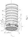
- Fig. 1 shows a perspective schematic representation of a corrugated hose 3 with the inventive device for pre-positioning 1 of a hose clamp 2 according to a first embodiment.
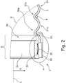
- Fig. 2 shows a detailed view X of the Fig. 1 according to the first embodiment.
- Fig. 3 shows a Y detailed view of the Fig. 2 according to the first embodiment.
- connection area A which is essentially cylindrical and has a receptacle 34 on the inside for connection to a connecting piece (not shown).
- This socket receptacle 34 has a rib-shaped contour in order to improve the static friction in the direction of the longitudinal axis L.
- a receptacle 35 for a sealing element such as e.g. an O-ring or the like.
- connection area A On the outside of the corrugated hose 3, a plurality of constrictions 30 and folds 31 lying between them adjoin the connection area A, which ensure the flexibility of the corrugated hose 3 and give it its name.
- the second constriction 30b and all other constrictions 30 arranged from this beyond the connection area A each have a pressure ring 4 which, among other things, has a pressure ring 4. increase the burst pressure of the corrugated hose 3.
- the corrugated hose 3 has a device for prepositioning 1 a hose clamp 2 with a housing 10.
- a clamp band 20 of the hose clamp 2 is guided and held in a corresponding recess 32 in the corrugated hose 3 between edges 33.
- a clamping mechanism 21 is accessible from the outside through a corresponding opening 11 in the housing 10 (cf. also Fig. 7a and 7b ).
- a first contact element 12 extends from the housing 10, which corresponds approximately to the width of the connection area A in the direction of the longitudinal axis L, in this exemplary embodiment, which engages in the first constriction 30a of the folded hose 3.
- the pressure ring 4 to be provided there is replaced by the first contact element 12, so that it can be dispensed with. Due to the static friction between the surfaces of the corrugated tube in the area of the first constriction 30a and the first contact element 12 prevents the device for prepositioning 1 from twisting or slipping in the circumferential direction. At the same time, the positioning and security against loss of the hose clamp 2 and the device for pre-positioning 1 is ensured by the positive engagement of the first contact element 12 in the first constriction 30a.
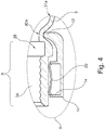
- Fig. 4 shows a detailed view Y of Fig. 2 according to a second embodiment.
- the clamp band 20 of the hose clamp 2 is guided and held in a corresponding recess 14 in the housing 10.
- Fig. 5 shows a detailed view X of the Fig. 1 according to a third embodiment.
- the first contact element 12 engages the first fold 31a of the folded hose 3, which is formed between the first and second constrictions 30a, 30b.
- the first contact element 12 has a half-shell-shaped contour on its inside, with which it encloses the fold 31 on both sides to such an extent that the form-fit is established and slipping or loss is prevented.
- Fig. 6 shows a schematic sectional view of a corrugated hose 3 with the inventive device for pre-positioning 1 of a hose clamp 2 according to a fourth embodiment.
- the corrugated hose 3 is shown over its entire length, ie with both ends and their connection areas A.
- each device for prepositioning 1 additionally has a second contact element 13, which connects to the first contact element 12.
- the flexibility up to the second contact element 13 is reduced or excluded, so that there is a smaller bending radius for the remaining bending area B of the corrugated tube 3 than without the second contact element 13.
- Fig. 7a shows a perspective schematic representation of a housing 10 of FIG Fig. 1 according to a fifth embodiment.
- the housing 10 of this exemplary embodiment has a cutout 15 which the housing opening 11 is diametrically opposite. This extends so far in the circumferential direction and in the longitudinal direction that the recess 15 can act as a viewing window 15 through which the correct fit of the clamp band 20 can be checked from the outside.
- the housing 10 has a structured outer surface 16 in order to increase the friction or the grip on the surface during assembly.
- the housing 10 in the fifth exemplary embodiment has a structure in the form of crossed grooves which intersect at right angles and each extend equally in the circumferential direction and in the longitudinal direction. As a result, diamond-shaped surfaces are formed between the grooves.
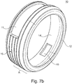
- Fig. 7b shows a perspective schematic representation of a housing 10 of FIG Fig. 1 according to a sixth embodiment. This embodiment differs only from the fifth embodiment of FIG Fig. 7a that the structuring of the outer surface 16 is carried out here by grooves running in the circumferential direction.
Landscapes
- Engineering & Computer Science (AREA)
- General Engineering & Computer Science (AREA)
- Mechanical Engineering (AREA)
- Clamps And Clips (AREA)
- Supports For Pipes And Cables (AREA)
Description
- Die Erfindung betrifft eine Schlauchanordnung, mit einem Faltenschlauch, einer Schlauchschelle, und einer Vorrichtung zur Vorpositionierung der Schlauchschelle auf dem Faltenschlauch gemäß dem Oberbegriff des Anspruchs 1.
- Es sind seit langem Montagehilfen bekannt, um eine Schlauchschelle im Anschlussbereich eines Schlauches verliersicher derart zu positionieren und zu fixieren, dass sie nach dem Aufstecken des Schlauches auf einen Stutzen oder dergleichen bereits in der richtigen Position vorhanden ist und nur noch gespannt werden muss, um eine sichere und druckdichte Verbindung zwischen Schlauch und Stutzen herzustellen.
- Als derartige Montagehilfen sind z.B. aus Elastomermaterial auf den Schlauch im Anschlussbereich aufgespritzte Erhebungen z.B. in Form von Haken oder Pilzen bekannt, die in korrespondierende Aussparungen des Schellenbandes eingreifen. Hierdurch kann gleichzeitig sowohl eine Sicherung des Schellenbandes in axialer sowie in Umfangsrichtung gegen Verschieben und Verrutschen des Schlauches als auch eine Sicherung in radialer Richtung gegen Abheben und Lösen des Schellenbandes von der Schlauchoberfläche erreicht werden.
- Ferner sind käfigartige Ummantelungen aus Kunststoff oder Metall bekannt, um die Schlauchschelle bei der Montage auf dem Schlauch an der gewünschten Position zu halten. Die
DE 10 2006 057 497 A1 betrifft ein System zur Vorpositionierung einer Schlauchschelle auf einem Schlauchende. Das System weist mehrere einzelne Fixierteile auf, die jeweils mit einem ersten U-förmigen Element in Längsrichtung auf den Rand des Schlauches aufgesteckt sind und in einem zweiten U-förmigen Element das Schellenband aufnehmen, um dieses am Rand des Schlauchendes zu positionieren und zu halten. - Zu den Schläuchen gehören auch die Faltenschläuche, welche in Umfangsrichtung verlaufende und in Längsrichtung beabstandete Einschnürungen mit dazwischenliegenden Falten aufweisen, so dass sich eine in Längsrichtung gewellte Oberfläche ergibt. Diese Einschnürungen ermöglichen es, Faltenschläuche zu biegen, ohne dass es hierdurch zum Einknicken des Schlauchquerschnittes kommt. Dabei schieben sich die Falten, d.h. die Abschnitte zwischen den Einschnürungen, auf der Innenseite der Biegung zusammen und die radial gegenüberliegenden Falten weiten sich, so dass es zwar zu einer geringfügigen aber gleichmäßigen und knickfreien Querschnittsverringerung im Bereich der Biegung kommt.
- Um die Biegesteifigkeit, den Berstdruck und die Aufweitung von Faltenschläuchen zu erhöhen, ist es bekannt, Metall- oder Kunststoffringe als sog. Druckringe in die Einschnürungen einzubringen, um diese zu verstärken. Hierdurch entstehen jedoch zusätzlich Kosten durch Material und Montageaufwand.
- Eine Aufgabe der vorliegenden Erfindung ist es, die Herstellung und bzw. oder Montage von Faltenschläuchen mit Schellen zu vereinfachen. Insbesondere sollen bei der Herstellung und bzw. oder Montage von Faltenschläuchen mit Druckringen mit Schellen die Herstellungs- und bzw. oder Montageschritte reduziert werden.
- Die Aufgabe wird erfindungsgemäß durch eine Schlauchanordnung gemäß Anspruch 1 gelöst. Vorteilhafte Weiterbildungen sind in den Unteransprüchen beschrieben.
- Hierbei liegt der Erfindung die Erkenntnis zugrunde, diese Vorrichtung nicht nur zur Vorpositionierung der Schlauchschelle sondern gleichzeitig auch als ersten integrierten Druckring zu verwenden. Auf diese Weise kann der Montageaufwand zur Aufbringung dieses Druckringes sowie der Druckring selbst eingespart werden. Ferner wird die Biegsamkeit des Faltenschlauches bis zu dem Bereich des ersten Kontaktelementes verhindert bzw. reduziert, so dass kleinere Biegeradien des Faltenschlauches erreicht werden. Des Weiteren wird die Schallabsorption verringert, ohne dass hierzu separate Maßnahmen und Elemente erforderlich sind. Auch wird die Radialsteifigkeit des Faltenschlauches durch das Kontaktelement verbessert.
- Hierzu weist die Vorrichtung zur Vorpositionierung ein erstes Kontaktelement auf, welches ausgebildet ist, in eine erste Einschnürung des Faltenschlauches einzugreifen und bzw. oder auf eine erste Falte des Faltenschlauches aufzugreifen. Unter einem Kontaktelement bzw. integrierten Druckring kann sowohl ein in Umfangsrichtung geschlossenes Element verstanden werden, welches nach der Montage in einer Einschnürung des Faltenschlauches liegt oder auf einer Falte des Faltenschlauches sitzt. Es kann auch ein Element vorgesehen werden, welches beide Funktionen ausübt. Ein derartiges Element kann zwischen Einschnürung und Falte mit der Oberfläche des Faltenschlauches durchgängig in Kontakt stehen oder auch einen Abstand aufweisen.
- In jedem Fall wird durch den Kontakt des ersten Kontaktelements bzw. des integrierten Druckrings mit der Oberfläche des Faltenschlauches eine derart kraftschlüssige Verbindung durch Haftreibung hergestellt, dass ein Verdrehen der Vorrichtung zur Vorpositionierung gegenüber dem Faltenschlauch um die Längsachse sicher verhindert wird. Gleichzeitig erfolgt eine sichere Positionierung der Vorrichtung zur Vorpositionierung in Längsrichtung durch die formschlüssige Wechselwirkung zwischen Einschnürung bzw. Falte des Faltenschlauches und Kontaktelement der Vorrichtung zur Vorpositionierung. Hierdurch kann auf Erhebungen im Anschlussbereich des Faltenschlauches für korrespondierende Aussparungen des Schlauchschellenbandes verzichtet werden.
- Vorteilhaft ist hierbei auch, dass durch radiales Eindrücken des Faltenschlauches dessen Querschnitt derart verringert werden kann, dass die kraftschlüssige Verbindung zum ersten Kontaktelement zumindest soweit wieder aufgehoben werden kann, dass auch nach der Montage der Vorrichtung zur Vorpositionierung auf dem Faltenschlauch deren Position in Umfangsrichtung überhaupt und insbesondere sehr einfach und schnell verändert werden kann, falls dies erforderlich ist.
- Weist der Faltenschlauch in seinen Einschnürungen bzw. auf seinen Falten radiale Erhebungen und bzw. oder Vertiefungen auf, so kann das Kontaktelement entsprechend gestaltet werden, um auf diese aufzugreifen bzw. in diese einzugreifen und auf diese Weise in Umfangsrichtung eine zusätzliche oder alternative Formschlüssigkeit gegen Verdrehung zu erreichen.
- Gemäß einem Aspekt der Erfindung weist die Vorrichtung zur Vorpositionierung ferner ein zweites Kontaktelement auf, welches sich von dem ersten Kontaktelement erstreckt und welches ausgebildet ist, in eine zweite Einschnürung des Faltenschlauches einzugreifen und bzw. oder auf eine zweite Falte des Faltenschlauches aufzugreifen. Auf diese Weise können zwei oder auch noch mehr Kontaktelemente hintereinander angeordnet werden, um noch mehr separate Druckringe einzusparen. Ferner kann hierdurch die Biegsamkeit und das akustische Verhalten des Faltenschlauches weiter beeinflusst werden.
- Gemäß der Erfindung weist die Vorrichtung zur Vorpositionierung ein Gehäuse auf, welches einen Anschlussbereich des Faltenschlauchs in Umfangsrichtung zumindest abschnittsweise, vorzugsweise vollständig, umgibt und von dem sich das erste Kontaktelement in Längsrichtung von dem Anschlussbereich weg erstreckt. Unter Anschlussbereich wird der Bereich eines Schlauchendes verstanden, welcher zur Verbindung mit einem Gegenstück wie z.B. zum Aufstecken auf einen Stutzen ausgebildet ist. Dieser Anschlussbereich ist bei einem Faltenschlauch faltenfrei ausgebildet und weist vorzugsweise im Inneren eine rippenförmige Kontur zur Erhöhung der Haftreibung in Längsrichtung auf, welche auch dichtend wirken können. Ferner kann eine Aufnahme für ein Dichtelement vorgesehen sein. Dem Schlauchende abgewandt schließt sich an den Anschlussbereich der mit Einschnürungen und Falten versehene Bereich des Faltenschlauches an. Daher erstreckt sich das erste Kontaktelement von dem Gehäuse über den Anschlussbereich hinweg, um dort in eine Einschnürung eingreifen bzw. auf eine Falte aufgreifen zu können. Dabei kann das erste Kontaktelement in die erste Einschnürung, die sich dem Anschlussbereich anschließt, eingreifen oder auch diese und weitere Einschnürungen überspringen, um in eine weiter vom Anschlussbereich beabstandete Einschnürung einzugreifen. Hierdurch können mit der Ausbildung eines einzigen Kontaktelementes mehrere Druckringe ersetzt, ein größerer Bereich hinsichtlich seiner Biegesteifigkeit und Schallabsorption reduziert sowie in der Radialsteifigkeit erhöht werden.
- Vorteilhaft ist auch, dass durch ein in Umfangsrichtung des Anschlussbereichs vollständig umgebendes Gehäuse die Montage des Faltenschlauches auf einem Stutzen vereinfacht und erleichtert werden kann. So werden Faltenschläuche bei der Montage auf einem Schlauchstutzen üblicherweise durch die händische Aufschiebehaltung meist in ovale Form gebracht. Das wiederum führt zur Erschwerung der Schlauchmontage. Wird jedoch das Schlauchende bei der Montage vom Gehäuse vollständig umfasst, bleibt der Schlauch bei der Montage rund. Dadurch ist eine bessere Schlauchmontage möglich.
- Gemäß der Erfindung weist das Gehäuse eine Offnung zur Aufnahme eines Spannmechanismus der Schlauchschelle auf. Hierdurch wird der Zugang zum Spannmechanismus sichergestellt, wenn das Schlauchschellenband ansonsten nach außen durch die Vorrichtung zur Vorpositionierung soweit verdeckt wird, dass ein Zugang zum Spannmechanismus nicht möglich ist.
- Gemäß einem weiteren Aspekt der Erfindung weist das Gehäuse eine in Umfangsrichtung verlaufende Aufnahme eines Schellenbands der Schlauchschelle auf. Auf diese Weise kann das Schellenband zuerst in der Vorrichtung zur Vorpositionierung aufgenommen und dann können beide zusammen auf dem Aufnahmebereich des Faltenschlauches montiert werden, so dass die Schlauchschelle richtig positioniert und dort sicher gehalten werden kann.
- Gemäß einem weiteren Aspekt der Erfindung weist das Gehäuse eine Mehrzahl von radialen Durchgängen auf. Hierdurch kann Material eingespart und das Gewicht der Vorrichtung zur Vorpositionierung reduziert werden.
- Gemäß einem weiteren Aspekt der Erfindung weist das Gehäuse eine Aussparung, welche vorzugsweise der Öffnung im Wesentlichen gegenüberliegend angeordnet ist, und bzw. oder eine strukturierte äußere Oberfläche auf. Die Aussparung dient als Sicht- bzw. Kontrollfenster, um den korrekten Sitz der Schelle bzw. deren Schellenbandes innerhalb des Gehäuses optisch erfassen zu können. Hierzu ist dieses Sichtfenster vorzugsweise der Öffnung für den Spannmechanismus gegenüberliegend angeordnet, da auch diese Öffnung zu diesem Zweck dient und auf diese Weise beide Sichtfenster gleichmäßig über den Umfang des Gehäuses verteilt sind und so die Lage des Schlauchschellenbandes bestmöglich mit zwei Sichtfenstern kontrolliert werden kann.
- Eine strukturierte äußere Oberfläche des Gehäuses vorzusehen ist deshalb von Vorteil, weil hierdurch die Rauigkeit bzw. der Gripp der Oberfläche und damit die Handhabung der Vorrichtung zur Vorpositionierung bzw. der Schlauchanordnung verbessert werden kann. Dies kann durch Rillen in Umfangsrichtung und damit senkrecht zur Montagerichtung oder auch gekreuzte Rillen oder dergleichen erfolgen.
- Die Erfindung betrifft eine Schlauchanordnung mit einem Faltenschlauch, einer Schlauchschelle und einer Vorrichtung zur Vorpositionierung der Schlauchschelle auf dem Faltenschlauch wie zuvor beschrieben. Die Montage dieser Anordnung kann durch die erfindungsgemäße Vorrichtung zur Vorpositionierung vereinfacht werden, wie zuvor erläutert. Durch den Kontakt des ersten Kontaktelements mit dem Faltenschlauch wird auch die Verliersicherheit dieser Vorrichtung und damit auch der vorpositionierten Schlauchschelle erreicht.
- Gemäß einem Aspekt der Erfindung weist der Faltenschlauch eine in Umfangsrichtung verlaufende Aufnahme eines Schellenbands der Schlauchschelle auf. Hierdurch kann die Schlauchschelle zuerst auf dem Faltenschlauch in dessen Aufnahmebereich positioniert und gegen Verlieren und Verrutschen von außen durch die Vorrichtung zur Vorpositionierung gesichert werden.
- Gemäß einem weiteren Aspekt der Erfindung weist der Faltenschlauch wenigstens eine weitere Einschnürung mit einem Druckring auf. Auf diese Weise wird die Biegsamkeit des Faltenschlauches durch die Ausbildung von Falten und Einschnürungen erreicht, auch wenn wenigstens ein Anschlussbereich des Faltenschlauches eine reduzierte Biegsamkeit aufweist.
- Ausführungsbeispiele und weitere Vorteile der Erfindung werden nachstehend im Zusammenhang mit den folgenden Figuren erläutert. Darin zeigt:
- Fig. 1
- eine perspektivische schematische Darstellung eines Faltenschlauches mit erfindungsgemäßer Vorrichtung zur Vorpositionierung einer Schlauchschelle gemäß einem ersten Ausführungsbeispiel;
- Fig. 2
- eine Detailansicht der
Fig. 1 gemäß dem ersten Ausführungsbeispiel; - Fig. 3
- eine Detailansicht der
Fig. 2 gemäß dem ersten Ausführungsbeispiel; - Fig. 4
- eine Detailansicht der
Fig. 2 gemäß einem zweiten Ausführungsbeispiel; - Fig. 5
- eine Detailansicht der
Fig. 1 gemäß einem dritten Ausführungsbeispiel; - Fig. 6
- eine schematische Schnittdarstellung eines Faltenschlauches mit erfindungsgemäßer Vorrichtung zur Vorpositionierung einer Schlauchschelle gemäß einem vierten Ausführungsbeispiel;
- Fig. 7a
- eine perspektivische schematische Darstellung eines Gehäuses der
Fig. 1 gemäß einem fünften Ausführungsbeispiel; und - Fig. 7b
- eine perspektivische schematische Darstellung eines Gehäuses der
Fig. 1 gemäß einem sechsten Ausführungsbeispiel. -
Fig. 1 zeigt eine perspektivische schematische Darstellung eines Faltenschlauches 3 mit erfindungsgemäßer Vorrichtung zur Vorpositionierung 1 einer Schlauchschelle 2 gemäß einem ersten Ausführungsbeispiel.Fig. 2 zeigt eine Detailansicht X derFig. 1 gemäß dem ersten Ausführungsbeispiel.Fig. 3 zeigt eine Y Detailansicht derFig. 2 gemäß dem ersten Ausführungsbeispiel. - Der Faltenschlauch 3 weist an seinem dargestellten Ende einen Anschlussbereich A auf, der im Wesentlichen zylindrisch ausgebildet ist und im Inneren eine Aufnahme 34 zur Verbindung mit einem Stutzen (nicht dargestellt) aufweist. Diese Stutzenaufnahme 34 weist eine rippenförmige Kontur auf, um die Haftreibung in Richtung der Längsachse L zu verbessern. An die Stutzenaufnahme 34 schließt sich eine Aufnahme 35 für ein Dichtelement wie z.B. einen O-Ring oder dergleichen an.
- An der Außenseite des Faltenschlauches 3 schließen sich an den Anschlussbereich A eine Vielzahl von Einschnürungen 30 und zwischen diesen liegende Falten 31 an, die für die Biegsamkeit des Faltenschlauches 3 sorgen und diesem seinen Namen geben. In diesem Ausführungsbeispiel weisen dabei die zweite Einschnürung 30b und alle weiteren, von dieser jenseits des Anschlussbereiches A angeordneten Einschnürungen 30 jeweils einen Druckring 4 auf, die u.a. den Berstdruck des Faltenschlauches 3 erhöhen.
- Im Anschlussbereich A weist der Faltenschlauch 3 eine Vorrichtung zur Vorpositionierung 1 einer Schlauchschelle 2 mit einem Gehäuse 10 auf. Ein Schellenband 20 der Schlauchschelle 2 wird in diesem Ausführungsbeispiel in einer korrespondierenden Aussparung 32 des Faltenschlauches 3 zwischen Rändern 33 geführt und gehalten. Ein Spannmechanismus 21 ist durch eine entsprechende Öffnung 11 des Gehäuses 10 von außen zugänglich (vgl. auch
Fig. 7a und7b ). - Von dem Gehäuse 10, welches in Richtung der Längsachse L etwa der Breite des Anschlussbereiches A entspricht, erstreckt sich vom Ende des Faltenschlauches 3 weg in diesem Ausführungsbeispiel ein erstes Kontaktelement 12, welches in die erste Einschnürung 30a des Faltenschlauches 3 eingreift. Hierdurch wird der dort sonst vorzusehende Druckring 4 durch das erste Kontaktelement 12 ersetzt, so dass auf diesen verzichtet werden kann. Durch die Haftreibung zwischen den Oberflächen des Faltenschlauches im Bereich der ersten Einschnürung 30a und des ersten Kontaktelements 12 wird ein Verdrehen oder Verrutschen der Vorrichtung zur Vorpositionierung 1 in Umfangsrichtung sicher verhindert. Gleichzeitig wird die Positionierung und Verliersicherheit der Schlauchschelle 2 sowie der Vorrichtung zur Vorpositionierung 1 durch den formschlüssigen Eingriff des ersten Kontaktelements 12 in die erste Einschnürung 30a gewährleistet.
-
Fig. 4 zeigt eine Detailansicht Y derFig. 2 gemäß einem zweiten Ausführungsbeispiel. In diesem Fall wird das Schellenband 20 der Schlauchschelle 2 in einer korrespondierenden Aussparung 14 des Gehäuses 10 geführt und gehalten. -
Fig. 5 zeigt eine Detailansicht X derFig. 1 gemäß einem dritten Ausführungsbeispiel. Hier greift das erste Kontaktelement 12 auf die erste Falte 31a des Faltenschlauches 3 auf, die zwischen der ersten und zweiten Einschnürung 30a, 30b ausgebildet wird. Zur Sicherstellung der Formschlüssigkeit in Richtung der Längsachse L weist das erste Kontaktelement 12 eine halbschalenförmige Kontur auf seiner Innenseite auf, mit der es die Falte 31 beidseits so weit umschließt, dass der Formschluss hergestellt und ein Verrutschen oder Verlieren verhindert wird. -
Fig. 6 zeigt eine schematische Schnittdarstellung eines Faltenschlauches 3 mit erfindungsgemäßer Vorrichtung zur Vorpositionierung 1 einer Schlauchschelle 2 gemäß einem vierten Ausführungsbeispiel. Hier ist der Faltenschlauch 3 über seine gesamte Länge, d.h. mit beiden Enden und deren Anschlussbereichen A, dargestellt. In diesem Fall weist jede Vorrichtung zur Vorpositionierung 1 zusätzlich ein zweites Kontaktelement 13 auf, welches sich an das erste Kontaktelement 12 anschließt. Hierdurch wird die Biegsamkeit bis zu dem zweiten Kontaktelement 13 reduziert bzw. ausgeschlossen, so dass sich für den restlichen Biegebereich B des Faltenschlauches 3 ein kleinerer Biegeradius ergibt als ohne das zweite Kontaktelement 13. -
Fig. 7a zeigt eine perspektivische schematische Darstellung eines Gehäuses 10 derFig. 1 gemäß einem fünften Ausführungsbeispiel. Das Gehäuse 10 dieses Ausführungsbeispiels weist zusätzlich zu den bereits beschriebenen Elementen eine Aussparung 15 auf, welche der Gehäuseöffnung 11 diametral gegenüber liegt. Diese erstreckt sich soweit in Umfangsrichtung sowie in Längsrichtung, dass die Aussparung 15 als Sichtfenster 15 wirken kann, durch das optisch der korrekte Sitz des Schellenbandes 20 von außen kontrolliert werden kann. - Ferner weist das Gehäuse 10 eine strukturierte äußere Oberfläche 16 auf, um die Reibung bzw. den Gripp an der Oberfläche bei der Montage zu erhöhen. Dazu weist das Gehäuse 10 in dem fünften Ausführungsbeispiel eine Strukturierung in Form von gekreuzten Rillen auf, die sich rechtwinklig schneiden und sich jeweils gleichermaßen in Umfangsrichtung und Längsrichtung erstrecken. Hierdurch werden zwischen den Rillen rautenförmige Flächen ausgebildet.
-
Fig. 7b zeigt eine perspektivische schematische Darstellung eines Gehäuses 10 derFig. 1 gemäß einem sechsten Ausführungsbeispiel. Dieses Ausführungsbeispiel unterscheidet sich lediglich dadurch von dem fünften Ausführungsbeispiel derFig. 7a , dass die Strukturierung der äußeren Oberfläche 16 hier durch in Umfangsrichtung verlaufende Rillen ausgeführt ist. - (Teil der Beschreibung)
- A
- Anschlussbereich des Faltenschlauchs 3
- B
- Biegebereich des Faltenschlauchs 3
- L
- Längsachse
- R
- radiale Richtung
- X
- Ausschnitt der
Figur 1 - Y
- Ausschnitt der
Figur 2 - 1
- Vorrichtung zur Vorpositionierung einer Schlauchschelle 2
- 10
- Gehäuse, Schellenumhausung
- 11
- Gehäuseöffnung
- 12
- erstes Kontaktelement, erster integrierter Druckring
- 13
- zweites Kontaktelement, zweiter integrierter Druckring
- 14
- Aufnahme eines Schellenbands 20 der Vorrichtung zur Vorpositionierung 1
- 15
- Aussparung des Gehäuses 10, Sichtfenster
- 16
- strukturierte äußere Oberfläche des Gehäuses 10
- 2
- Schlauchschelle
- 20
- Schellenband
- 21
- Spannmechanismus
- 3
- Faltenschlauch
- 30
- weitere Einschnürungen jenseits der zweiten Einschnürung 30b
- 30a
- erste Einschnürung
- 30b
- zweite Einschnürung
- 31
- weiteren Falten jenseits der ersten Falte 31a
- 31a
- erste Falte
- 32
- Aufnahme eines Schellenbands 20 des Faltenschlauches 3
- 33
- Ränder der Schellenbandaufnahme 32
- 34
- Aufnahme eines Stutzens oder dergleichen
- 35
- Aufnahme eines Dichtelements
- 4
- Druckring
Claims (7)
- Schlauchanordnung, mit
einem Faltenschlauch (3),
einer Schlauchschelle (2), und
einer Vorrichtung zur Vorpositionierung (1) der Schlauchschelle (2) auf dem Faltenschlauch (3) mit einem ersten Kontaktelement (12), welches in eine erste Einschnürung (30a) des Faltenschlauches (3) eingreift und/oder auf eine erste Falte (31a) des Faltenschlauches (3) aufgreift,
gekennzeichnet dadurch, dass
die Vorrichtung zur Vorpositionierung (1) ferner ein Gehäuse (10) aufweist, welches einen Anschlussbereich (A) des Faltenschlauchs (3) in Umfangsrichtung zumindest abschnittsweise, vorzugsweise vollständig, umgibt und von dem sich das erste Kontaktelement (12) in Längsrichtung (L) von dem Anschlussbereich (A) weg erstreckt,
wobei das Gehäuse (10) eine Öffnung (11) zur Aufnahme eines Spannmechanismus (21) der Schlauchschelle (2) aufweist. - Schlauchanordnung nach Anspruch 1, ferner mit
einem zweiten Kontaktelement (13), welches sich von dem ersten Kontaktelement (12) erstreckt und welches ausgebildet ist, in eine zweite Einschnürung (30b) des Faltenschlauches (3) einzugreifen und/oder auf eine zweite Falte (31b) des Faltenschlauches (3) aufzugreifen. - Schlauchanordnung nach einem der vorherigen Ansprüche,
wobei das Gehäuse (10) eine in Umfangsrichtung verlaufende Aufnahme (14) eines Schellenbands (20) der Schlauchschelle (2) aufweist. - Schlauchanordnung nach einem der vorherigen Ansprüche,
wobei das Gehäuse (10) eine Mehrzahl von radialen Durchgängen aufweist. - Schlauchanordnung nach einem der vorherigen Ansprüche,
wobei das Gehäuse (10) eine Aussparung (15) aufweist, welche vorzugsweise der Öffnung (11) im Wesentlichen gegenüberliegend angeordnet ist, und/oder wobei das Gehäuse (10) eine strukturierte äußere Oberfläche (16) aufweist. - Schlauchanordnung nach einem der vorherigen Ansprüche,
wobei der Faltenschlauch (3) eine in Umfangsrichtung verlaufende Aufnahme (32) eines Schellenbands (20) der Schlauchschelle (2) aufweist. - Schlauchanordnung nach einem der vorherigen Ansprüche,
wobei der Faltenschlauch (3) wenigstens eine weitere Einschnürung (30) mit einem Druckring (4) aufweist.
Applications Claiming Priority (1)
| Application Number | Priority Date | Filing Date | Title |
|---|---|---|---|
| DE102013226001.6A DE102013226001A1 (de) | 2013-12-16 | 2013-12-16 | Vorrichtung zur Vorpositionierung einer Schlauchschelle auf einem Faltenschlauch |
Publications (2)
| Publication Number | Publication Date |
|---|---|
| EP2899442A1 EP2899442A1 (de) | 2015-07-29 |
| EP2899442B1 true EP2899442B1 (de) | 2020-07-01 |
Family
ID=51687922
Family Applications (1)
| Application Number | Title | Priority Date | Filing Date |
|---|---|---|---|
| EP14188416.3A Active EP2899442B1 (de) | 2013-12-16 | 2014-10-10 | Vorrichtung zur Vorpositionierung einer Schlauchschelle auf einem Faltenschlauch |
Country Status (2)
| Country | Link |
|---|---|
| EP (1) | EP2899442B1 (de) |
| DE (1) | DE102013226001A1 (de) |
Citations (2)
| Publication number | Priority date | Publication date | Assignee | Title |
|---|---|---|---|---|
| US20050161947A1 (en) * | 2003-10-28 | 2005-07-28 | Skinner James W. | Sealing system for pipelines |
| US20090295153A1 (en) * | 2008-05-27 | 2009-12-03 | Springseal, Inc. | Pipe coupling assembly |
Family Cites Families (6)
| Publication number | Priority date | Publication date | Assignee | Title |
|---|---|---|---|---|
| US3144262A (en) * | 1961-07-20 | 1964-08-11 | Frank J Reynolds | Quick connection for male-female coupling |
| US4135744A (en) * | 1976-05-13 | 1979-01-23 | Robert E. Fouts | Terminal fitting for a tubular conduit |
| DE8032997U1 (de) * | 1979-12-20 | 1981-04-02 | Smiths Industries Ltd., London | Flexibles rohr |
| DE3524074A1 (de) * | 1985-07-05 | 1987-01-15 | Rasmussen Gmbh | Vorrichtung zum befestigen einer schlauchschelle auf einem schlauch |
| WO2000031456A1 (en) * | 1998-11-23 | 2000-06-02 | Thermopol Limited | A clamp and hose combination |
| DE102006057497A1 (de) | 2006-08-25 | 2008-03-27 | Mündener Gummiwerk Gmbh | System zur Vorpositionierung einer Schlauchschelle, insbesondere eines Ladeluft- und Kühlwasserschlauchs |
-
2013
- 2013-12-16 DE DE102013226001.6A patent/DE102013226001A1/de not_active Withdrawn
-
2014
- 2014-10-10 EP EP14188416.3A patent/EP2899442B1/de active Active
Patent Citations (2)
| Publication number | Priority date | Publication date | Assignee | Title |
|---|---|---|---|---|
| US20050161947A1 (en) * | 2003-10-28 | 2005-07-28 | Skinner James W. | Sealing system for pipelines |
| US20090295153A1 (en) * | 2008-05-27 | 2009-12-03 | Springseal, Inc. | Pipe coupling assembly |
Also Published As
| Publication number | Publication date |
|---|---|
| EP2899442A1 (de) | 2015-07-29 |
| DE102013226001A1 (de) | 2015-06-18 |
Similar Documents
| Publication | Publication Date | Title |
|---|---|---|
| DE3136018C1 (de) | Vorrichtung zum Befestigen eines Schlauches auf einem Rohrstutzen | |
| EP1600679B1 (de) | Verbindungsanordnung aus Kunststoff zum Festlegen eines Schlauches | |
| EP2250420B1 (de) | Schellenfixierung für ein Schlauchende | |
| EP2757299B1 (de) | Rohrklemme | |
| EP3577012B1 (de) | Längsverstellbare lenkwelle für ein kraftfahrzeug und profilhülse für eine lenkwelle | |
| EP2413012B1 (de) | Steckverbindung | |
| WO2017149104A1 (de) | Vorpositionierer für eine profilschelle und verbindungsanordnung mit einem derartigen vorpositionierer | |
| DE102011089189B4 (de) | Abschirmvorrichtung von rotierenden Bauteilen zur gezielten Beeinflussung der Förderrichtung des Ölstromes | |
| EP3679286B1 (de) | Verbindungsanordnung für rohre | |
| DE19542463B4 (de) | Rohrkupplung | |
| EP4405606A1 (de) | Steckverbinder mit vormontagesicherung | |
| EP3293496B1 (de) | Längenmesseinrichtung und verfahren zu deren montage | |
| DE102012019043B4 (de) | Kugelgelenk und Verfahren zur Herstellung eines Kugelgelenks | |
| EP3626898B1 (de) | Profilrohrsystem | |
| EP2899442A1 (de) | Vorrichtung zur Vorpositionierung einer Schlauchschelle auf einem Faltenschlauch | |
| EP3434953B1 (de) | Sicherungsring, abgasrohrsystem mit sicherungsring | |
| DE102016119519A1 (de) | Lenksäulenmodul für ein Fahrzeug, Lenksäulenanordnung, Fahrzeug und Verfahren zum Zusammenbau einer Lenksäulenanordnung | |
| DE102010021411A1 (de) | Steckverbindungsanordnung und Befestigungseinrichtung | |
| EP2982893B1 (de) | Rohrklemmanordnung | |
| DE102010028360B4 (de) | Verbindungsanordnung zum Festlegen einer Schlauchleitung, insbesondere einer Bremsschlauchleitung an einem Halter | |
| EP3696457A1 (de) | Verbindungsvorrichtung für rohre | |
| EP4011788B1 (de) | Tubenhalter | |
| DE102010060198B4 (de) | Lager für einen Stabilisator eines Kraftfahrzeugs | |
| EP2194308B1 (de) | Kupplungsstück für Wellenschlauch-Anschlussteile | |
| EP3366851A1 (de) | Universal-füllventil-set |
Legal Events
| Date | Code | Title | Description |
|---|---|---|---|
| PUAI | Public reference made under article 153(3) epc to a published international application that has entered the european phase |
Free format text: ORIGINAL CODE: 0009012 |
|
| 17P | Request for examination filed |
Effective date: 20141010 |
|
| AK | Designated contracting states |
Kind code of ref document: A1 Designated state(s): AL AT BE BG CH CY CZ DE DK EE ES FI FR GB GR HR HU IE IS IT LI LT LU LV MC MK MT NL NO PL PT RO RS SE SI SK SM TR |
|
| AX | Request for extension of the european patent |
Extension state: BA ME |
|
| 17P | Request for examination filed |
Effective date: 20160129 |
|
| RBV | Designated contracting states (corrected) |
Designated state(s): AL AT BE BG CH CY CZ DE DK EE ES FI FR GB GR HR HU IE IS IT LI LT LU LV MC MK MT NL NO PL PT RO RS SE SI SK SM TR |
|
| STAA | Information on the status of an ep patent application or granted ep patent |
Free format text: STATUS: EXAMINATION IS IN PROGRESS |
|
| 17Q | First examination report despatched |
Effective date: 20190220 |
|
| GRAP | Despatch of communication of intention to grant a patent |
Free format text: ORIGINAL CODE: EPIDOSNIGR1 |
|
| STAA | Information on the status of an ep patent application or granted ep patent |
Free format text: STATUS: GRANT OF PATENT IS INTENDED |
|
| INTG | Intention to grant announced |
Effective date: 20200318 |
|
| GRAS | Grant fee paid |
Free format text: ORIGINAL CODE: EPIDOSNIGR3 |
|
| GRAA | (expected) grant |
Free format text: ORIGINAL CODE: 0009210 |
|
| STAA | Information on the status of an ep patent application or granted ep patent |
Free format text: STATUS: THE PATENT HAS BEEN GRANTED |
|
| AK | Designated contracting states |
Kind code of ref document: B1 Designated state(s): AL AT BE BG CH CY CZ DE DK EE ES FI FR GB GR HR HU IE IS IT LI LT LU LV MC MK MT NL NO PL PT RO RS SE SI SK SM TR |
|
| REG | Reference to a national code |
Ref country code: CH Ref legal event code: EP Ref country code: AT Ref legal event code: REF Ref document number: 1286509 Country of ref document: AT Kind code of ref document: T Effective date: 20200715 |
|
| REG | Reference to a national code |
Ref country code: IE Ref legal event code: FG4D Free format text: LANGUAGE OF EP DOCUMENT: GERMAN |
|
| REG | Reference to a national code |
Ref country code: DE Ref legal event code: R096 Ref document number: 502014014384 Country of ref document: DE |
|
| REG | Reference to a national code |
Ref country code: LT Ref legal event code: MG4D |
|
| PG25 | Lapsed in a contracting state [announced via postgrant information from national office to epo] |
Ref country code: BG Free format text: LAPSE BECAUSE OF FAILURE TO SUBMIT A TRANSLATION OF THE DESCRIPTION OR TO PAY THE FEE WITHIN THE PRESCRIBED TIME-LIMIT Effective date: 20201001 |
|
| REG | Reference to a national code |
Ref country code: NL Ref legal event code: MP Effective date: 20200701 |
|
| RAP2 | Party data changed (patent owner data changed or rights of a patent transferred) |
Owner name: CONTITECH MGW GMBH |
|
| PG25 | Lapsed in a contracting state [announced via postgrant information from national office to epo] |
Ref country code: LT Free format text: LAPSE BECAUSE OF FAILURE TO SUBMIT A TRANSLATION OF THE DESCRIPTION OR TO PAY THE FEE WITHIN THE PRESCRIBED TIME-LIMIT Effective date: 20200701 Ref country code: HR Free format text: LAPSE BECAUSE OF FAILURE TO SUBMIT A TRANSLATION OF THE DESCRIPTION OR TO PAY THE FEE WITHIN THE PRESCRIBED TIME-LIMIT Effective date: 20200701 Ref country code: ES Free format text: LAPSE BECAUSE OF FAILURE TO SUBMIT A TRANSLATION OF THE DESCRIPTION OR TO PAY THE FEE WITHIN THE PRESCRIBED TIME-LIMIT Effective date: 20200701 Ref country code: CZ Free format text: LAPSE BECAUSE OF FAILURE TO SUBMIT A TRANSLATION OF THE DESCRIPTION OR TO PAY THE FEE WITHIN THE PRESCRIBED TIME-LIMIT Effective date: 20200701 Ref country code: PT Free format text: LAPSE BECAUSE OF FAILURE TO SUBMIT A TRANSLATION OF THE DESCRIPTION OR TO PAY THE FEE WITHIN THE PRESCRIBED TIME-LIMIT Effective date: 20201102 Ref country code: NO Free format text: LAPSE BECAUSE OF FAILURE TO SUBMIT A TRANSLATION OF THE DESCRIPTION OR TO PAY THE FEE WITHIN THE PRESCRIBED TIME-LIMIT Effective date: 20201001 Ref country code: SE Free format text: LAPSE BECAUSE OF FAILURE TO SUBMIT A TRANSLATION OF THE DESCRIPTION OR TO PAY THE FEE WITHIN THE PRESCRIBED TIME-LIMIT Effective date: 20200701 Ref country code: GR Free format text: LAPSE BECAUSE OF FAILURE TO SUBMIT A TRANSLATION OF THE DESCRIPTION OR TO PAY THE FEE WITHIN THE PRESCRIBED TIME-LIMIT Effective date: 20201002 Ref country code: FI Free format text: LAPSE BECAUSE OF FAILURE TO SUBMIT A TRANSLATION OF THE DESCRIPTION OR TO PAY THE FEE WITHIN THE PRESCRIBED TIME-LIMIT Effective date: 20200701 |
|
| PG25 | Lapsed in a contracting state [announced via postgrant information from national office to epo] |
Ref country code: PL Free format text: LAPSE BECAUSE OF FAILURE TO SUBMIT A TRANSLATION OF THE DESCRIPTION OR TO PAY THE FEE WITHIN THE PRESCRIBED TIME-LIMIT Effective date: 20200701 Ref country code: LV Free format text: LAPSE BECAUSE OF FAILURE TO SUBMIT A TRANSLATION OF THE DESCRIPTION OR TO PAY THE FEE WITHIN THE PRESCRIBED TIME-LIMIT Effective date: 20200701 Ref country code: RS Free format text: LAPSE BECAUSE OF FAILURE TO SUBMIT A TRANSLATION OF THE DESCRIPTION OR TO PAY THE FEE WITHIN THE PRESCRIBED TIME-LIMIT Effective date: 20200701 Ref country code: IS Free format text: LAPSE BECAUSE OF FAILURE TO SUBMIT A TRANSLATION OF THE DESCRIPTION OR TO PAY THE FEE WITHIN THE PRESCRIBED TIME-LIMIT Effective date: 20201101 |
|
| PG25 | Lapsed in a contracting state [announced via postgrant information from national office to epo] |
Ref country code: NL Free format text: LAPSE BECAUSE OF FAILURE TO SUBMIT A TRANSLATION OF THE DESCRIPTION OR TO PAY THE FEE WITHIN THE PRESCRIBED TIME-LIMIT Effective date: 20200701 |
|
| REG | Reference to a national code |
Ref country code: DE Ref legal event code: R097 Ref document number: 502014014384 Country of ref document: DE |
|
| PG25 | Lapsed in a contracting state [announced via postgrant information from national office to epo] |
Ref country code: DK Free format text: LAPSE BECAUSE OF FAILURE TO SUBMIT A TRANSLATION OF THE DESCRIPTION OR TO PAY THE FEE WITHIN THE PRESCRIBED TIME-LIMIT Effective date: 20200701 Ref country code: EE Free format text: LAPSE BECAUSE OF FAILURE TO SUBMIT A TRANSLATION OF THE DESCRIPTION OR TO PAY THE FEE WITHIN THE PRESCRIBED TIME-LIMIT Effective date: 20200701 Ref country code: IT Free format text: LAPSE BECAUSE OF FAILURE TO SUBMIT A TRANSLATION OF THE DESCRIPTION OR TO PAY THE FEE WITHIN THE PRESCRIBED TIME-LIMIT Effective date: 20200701 Ref country code: SM Free format text: LAPSE BECAUSE OF FAILURE TO SUBMIT A TRANSLATION OF THE DESCRIPTION OR TO PAY THE FEE WITHIN THE PRESCRIBED TIME-LIMIT Effective date: 20200701 Ref country code: RO Free format text: LAPSE BECAUSE OF FAILURE TO SUBMIT A TRANSLATION OF THE DESCRIPTION OR TO PAY THE FEE WITHIN THE PRESCRIBED TIME-LIMIT Effective date: 20200701 |
|
| PLBE | No opposition filed within time limit |
Free format text: ORIGINAL CODE: 0009261 |
|
| STAA | Information on the status of an ep patent application or granted ep patent |
Free format text: STATUS: NO OPPOSITION FILED WITHIN TIME LIMIT |
|
| PG25 | Lapsed in a contracting state [announced via postgrant information from national office to epo] |
Ref country code: AL Free format text: LAPSE BECAUSE OF FAILURE TO SUBMIT A TRANSLATION OF THE DESCRIPTION OR TO PAY THE FEE WITHIN THE PRESCRIBED TIME-LIMIT Effective date: 20200701 |
|
| REG | Reference to a national code |
Ref country code: CH Ref legal event code: PL |
|
| 26N | No opposition filed |
Effective date: 20210406 |
|
| GBPC | Gb: european patent ceased through non-payment of renewal fee |
Effective date: 20201010 |
|
| PG25 | Lapsed in a contracting state [announced via postgrant information from national office to epo] |
Ref country code: SK Free format text: LAPSE BECAUSE OF FAILURE TO SUBMIT A TRANSLATION OF THE DESCRIPTION OR TO PAY THE FEE WITHIN THE PRESCRIBED TIME-LIMIT Effective date: 20200701 Ref country code: LU Free format text: LAPSE BECAUSE OF NON-PAYMENT OF DUE FEES Effective date: 20201010 Ref country code: MC Free format text: LAPSE BECAUSE OF FAILURE TO SUBMIT A TRANSLATION OF THE DESCRIPTION OR TO PAY THE FEE WITHIN THE PRESCRIBED TIME-LIMIT Effective date: 20200701 |
|
| REG | Reference to a national code |
Ref country code: BE Ref legal event code: MM Effective date: 20201031 |
|
| PG25 | Lapsed in a contracting state [announced via postgrant information from national office to epo] |
Ref country code: FR Free format text: LAPSE BECAUSE OF NON-PAYMENT OF DUE FEES Effective date: 20201031 |
|
| PG25 | Lapsed in a contracting state [announced via postgrant information from national office to epo] |
Ref country code: BE Free format text: LAPSE BECAUSE OF NON-PAYMENT OF DUE FEES Effective date: 20201031 Ref country code: CH Free format text: LAPSE BECAUSE OF NON-PAYMENT OF DUE FEES Effective date: 20201031 Ref country code: SI Free format text: LAPSE BECAUSE OF FAILURE TO SUBMIT A TRANSLATION OF THE DESCRIPTION OR TO PAY THE FEE WITHIN THE PRESCRIBED TIME-LIMIT Effective date: 20200701 Ref country code: LI Free format text: LAPSE BECAUSE OF NON-PAYMENT OF DUE FEES Effective date: 20201031 Ref country code: GB Free format text: LAPSE BECAUSE OF NON-PAYMENT OF DUE FEES Effective date: 20201010 |
|
| PG25 | Lapsed in a contracting state [announced via postgrant information from national office to epo] |
Ref country code: IE Free format text: LAPSE BECAUSE OF NON-PAYMENT OF DUE FEES Effective date: 20201010 |
|
| REG | Reference to a national code |
Ref country code: AT Ref legal event code: MM01 Ref document number: 1286509 Country of ref document: AT Kind code of ref document: T Effective date: 20201010 |
|
| PG25 | Lapsed in a contracting state [announced via postgrant information from national office to epo] |
Ref country code: AT Free format text: LAPSE BECAUSE OF NON-PAYMENT OF DUE FEES Effective date: 20201010 |
|
| PG25 | Lapsed in a contracting state [announced via postgrant information from national office to epo] |
Ref country code: TR Free format text: LAPSE BECAUSE OF FAILURE TO SUBMIT A TRANSLATION OF THE DESCRIPTION OR TO PAY THE FEE WITHIN THE PRESCRIBED TIME-LIMIT Effective date: 20200701 Ref country code: MT Free format text: LAPSE BECAUSE OF FAILURE TO SUBMIT A TRANSLATION OF THE DESCRIPTION OR TO PAY THE FEE WITHIN THE PRESCRIBED TIME-LIMIT Effective date: 20200701 Ref country code: CY Free format text: LAPSE BECAUSE OF FAILURE TO SUBMIT A TRANSLATION OF THE DESCRIPTION OR TO PAY THE FEE WITHIN THE PRESCRIBED TIME-LIMIT Effective date: 20200701 |
|
| PG25 | Lapsed in a contracting state [announced via postgrant information from national office to epo] |
Ref country code: MK Free format text: LAPSE BECAUSE OF FAILURE TO SUBMIT A TRANSLATION OF THE DESCRIPTION OR TO PAY THE FEE WITHIN THE PRESCRIBED TIME-LIMIT Effective date: 20200701 |
|
| REG | Reference to a national code |
Ref country code: DE Ref legal event code: R081 Ref document number: 502014014384 Country of ref document: DE Owner name: CONTITECH TECHNO-CHEMIE GMBH, DE Free format text: FORMER OWNER: CONTITECH MGW GMBH, 34346 HANN. MUENDEN, DE |
|
| PGFP | Annual fee paid to national office [announced via postgrant information from national office to epo] |
Ref country code: DE Payment date: 20251020 Year of fee payment: 12 |