EP2899424B1 - Flugzeugbremsanlage - Google Patents
Flugzeugbremsanlage Download PDFInfo
- Publication number
- EP2899424B1 EP2899424B1 EP14191373.1A EP14191373A EP2899424B1 EP 2899424 B1 EP2899424 B1 EP 2899424B1 EP 14191373 A EP14191373 A EP 14191373A EP 2899424 B1 EP2899424 B1 EP 2899424B1
- Authority
- EP
- European Patent Office
- Prior art keywords
- ema
- fluid
- hydraulic
- housing
- brake
- Prior art date
- Legal status (The legal status is an assumption and is not a legal conclusion. Google has not performed a legal analysis and makes no representation as to the accuracy of the status listed.)
- Active
Links
Images



Classifications
-
- B—PERFORMING OPERATIONS; TRANSPORTING
- B64—AIRCRAFT; AVIATION; COSMONAUTICS
- B64C—AEROPLANES; HELICOPTERS
- B64C25/00—Alighting gear
- B64C25/32—Alighting gear characterised by elements which contact the ground or similar surface
- B64C25/42—Arrangement or adaptation of brakes
- B64C25/44—Actuating mechanisms
-
- B—PERFORMING OPERATIONS; TRANSPORTING
- B60—VEHICLES IN GENERAL
- B60T—VEHICLE BRAKE CONTROL SYSTEMS OR PARTS THEREOF; BRAKE CONTROL SYSTEMS OR PARTS THEREOF, IN GENERAL; ARRANGEMENT OF BRAKING ELEMENTS ON VEHICLES IN GENERAL; PORTABLE DEVICES FOR PREVENTING UNWANTED MOVEMENT OF VEHICLES; VEHICLE MODIFICATIONS TO FACILITATE COOLING OF BRAKES
- B60T13/00—Transmitting braking action from initiating means to ultimate brake actuator with power assistance or drive; Brake systems incorporating such transmitting means, e.g. air-pressure brake systems
- B60T13/10—Transmitting braking action from initiating means to ultimate brake actuator with power assistance or drive; Brake systems incorporating such transmitting means, e.g. air-pressure brake systems with fluid assistance, drive, or release
- B60T13/58—Combined or convertible systems
- B60T13/588—Combined or convertible systems both fluid and mechanical assistance or drive
-
- B—PERFORMING OPERATIONS; TRANSPORTING
- B60—VEHICLES IN GENERAL
- B60T—VEHICLE BRAKE CONTROL SYSTEMS OR PARTS THEREOF; BRAKE CONTROL SYSTEMS OR PARTS THEREOF, IN GENERAL; ARRANGEMENT OF BRAKING ELEMENTS ON VEHICLES IN GENERAL; PORTABLE DEVICES FOR PREVENTING UNWANTED MOVEMENT OF VEHICLES; VEHICLE MODIFICATIONS TO FACILITATE COOLING OF BRAKES
- B60T13/00—Transmitting braking action from initiating means to ultimate brake actuator with power assistance or drive; Brake systems incorporating such transmitting means, e.g. air-pressure brake systems
- B60T13/74—Transmitting braking action from initiating means to ultimate brake actuator with power assistance or drive; Brake systems incorporating such transmitting means, e.g. air-pressure brake systems with electrical assistance or drive
- B60T13/741—Transmitting braking action from initiating means to ultimate brake actuator with power assistance or drive; Brake systems incorporating such transmitting means, e.g. air-pressure brake systems with electrical assistance or drive acting on an ultimate actuator
-
- F—MECHANICAL ENGINEERING; LIGHTING; HEATING; WEAPONS; BLASTING
- F16—ENGINEERING ELEMENTS AND UNITS; GENERAL MEASURES FOR PRODUCING AND MAINTAINING EFFECTIVE FUNCTIONING OF MACHINES OR INSTALLATIONS; THERMAL INSULATION IN GENERAL
- F16D—COUPLINGS FOR TRANSMITTING ROTATION; CLUTCHES; BRAKES
- F16D65/00—Parts or details
- F16D65/02—Braking members; Mounting thereof
- F16D65/12—Discs; Drums for disc brakes
-
- F—MECHANICAL ENGINEERING; LIGHTING; HEATING; WEAPONS; BLASTING
- F16—ENGINEERING ELEMENTS AND UNITS; GENERAL MEASURES FOR PRODUCING AND MAINTAINING EFFECTIVE FUNCTIONING OF MACHINES OR INSTALLATIONS; THERMAL INSULATION IN GENERAL
- F16D—COUPLINGS FOR TRANSMITTING ROTATION; CLUTCHES; BRAKES
- F16D65/00—Parts or details
- F16D65/14—Actuating mechanisms for brakes; Means for initiating operation at a predetermined position
- F16D65/16—Actuating mechanisms for brakes; Means for initiating operation at a predetermined position arranged in or on the brake
- F16D65/18—Actuating mechanisms for brakes; Means for initiating operation at a predetermined position arranged in or on the brake adapted for drawing members together, e.g. for disc brakes
-
- F—MECHANICAL ENGINEERING; LIGHTING; HEATING; WEAPONS; BLASTING
- F16—ENGINEERING ELEMENTS AND UNITS; GENERAL MEASURES FOR PRODUCING AND MAINTAINING EFFECTIVE FUNCTIONING OF MACHINES OR INSTALLATIONS; THERMAL INSULATION IN GENERAL
- F16D—COUPLINGS FOR TRANSMITTING ROTATION; CLUTCHES; BRAKES
- F16D2121/00—Type of actuator operation force
- F16D2121/02—Fluid pressure
- F16D2121/04—Fluid pressure acting on a piston-type actuator, e.g. for liquid pressure
-
- F—MECHANICAL ENGINEERING; LIGHTING; HEATING; WEAPONS; BLASTING
- F16—ENGINEERING ELEMENTS AND UNITS; GENERAL MEASURES FOR PRODUCING AND MAINTAINING EFFECTIVE FUNCTIONING OF MACHINES OR INSTALLATIONS; THERMAL INSULATION IN GENERAL
- F16D—COUPLINGS FOR TRANSMITTING ROTATION; CLUTCHES; BRAKES
- F16D2121/00—Type of actuator operation force
- F16D2121/18—Electric or magnetic
- F16D2121/24—Electric or magnetic using motors
Definitions
- the present invention relates to aircraft braking systems and, more specifically, to a hybrid electromechanical - hydraulic braking system.
- Aircraft may employ hydraulic or electro-mechanical braking systems.
- Typical hydraulic braking systems employ pistons driven by hydraulic pressure fed from reservoirs. These hydraulic braking systems may be low cost and relatively low weight.
- electro-mechanical brake systems eliminate the need for all hydraulics which improves field maintenance and reduces environmental risk from hydraulic leakage.
- an aircraft brake system as defined in claim 1.
- the compression chambers as defined in claim 7 may also be configured to hold extra fluid to account for brake wear.
- any reference to singular includes plural embodiments, and any reference to more than one component or step may include a singular embodiment or step.
- any reference to attached, fixed, connected or the like may include permanent, removable, temporary, partial, full and/or any other possible attachment option.
- any reference to without contact (or similar phrases) may also include reduced contact or minimal contact.
- phrases such as “make contact with,” “coupled to,” “touch,” “interface with” and “engage” may be used interchangeably to the extent that this is not excluded by the claims.
- the hydraulic adjusters are driven by the electromechanical actuators, providing the hybrid braking system with benefits (e.g., force generation) and/or responsiveness of hydraulic actuation while also being configured as a self-contained system.
- the electromechanical actuators act to create hydraulic pressure to drive the hydraulic adjusters.
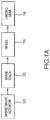
- a hybrid brake actuator 120 is coupled to and/or configured to attach to brake stack 112.
- Brake stack 112 may attach and/or be installed on wheel 110.
- Wheel 110 may attach and/or support landing gear 114 of an aircraft.
- Hybrid brake actuator 120 is configured to exert a force on brake stack 112 to slow and/or stop wheel 110.
- hybrid actuator 120 may apply a force to a brake stack contained within brake stack 112 to stop an airplane during a landing and/or taxi event (e.g., while the aircraft is on the ground).
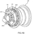
- hybrid brake actuator 220 may couple to brake stack 212.
- Hybrid brake actuator 220 may be coupled to brake stack 212 with any suitable fastener including, for example, fasteners 216-1, 216-2 and 216-3.
- Brake stack 212 may attach to, couple to, and/or be contained within wheel 210.
- hybrid brake actuator 220 comprises one or more electric motor actuators 222 (e.g., shown as EMA 222-1 and EMA 222-2).
- EMA 222 may be coupled to and/or attached to housing 226 in any suitable fashion.
- EMA 222 may be a module that removably couples to housing 226.
- EMA 222 may couple to housing 226 in any suitable orientation.
- a longitudinal centerline A-A' of EMA 222 may be generally parallel to a top surface B of housing 226.
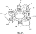
- EMA 222 is operatively coupled to one or more hydraulic adjusters 224 (e.g. shown as hydraulic adjuster 224-1, hydraulic adjuster 224-2, hydraulic adjuster 224-3, hydraulic adjuster 224-4, hydraulic adjuster 224-5, and hydraulic adjuster 224-6).
- hydraulic adjuster 224 e.g. shown as hydraulic adjuster 224-1, hydraulic adjuster 224-2, hydraulic adjuster 224-3, hydraulic adjuster 224-4, hydraulic adjuster 224-5, and hydraulic adjuster 224-6.
- Each of EMA 222 and hydraulic adjuster 224 may be operatively installed on and/or contained on housing 226.
- hybrid brake actuator 220 comprises and/or is configured with a supply of fluid (e.g., oil and/or hydraulic fluid).
- the fluid may be contained within a volume of housing 226, EMA 222, and/or hydraulic adjuster 224.
- housing 226 may comprise various volumes, ports, channels, and/or fluid passages.
- the volumes, ports, channels, and/or fluid passages of housing 226 may be configured to conduct, transport, contain and/or store fluid (e.g., oil and/or hydraulic fluid).
- the volumes, ports, channels, and/or fluid passages may operatively couple, facilitate, and/or enable fluid communication between EMA 222 and hydraulic adjuster 224.
- EMA 222 may be electrically actuated to create a hydraulic pressure that may drive and/or actuate hydraulic adjuster 224.
- each hydraulic adjuster 224 comprises a piston 225 (e.g., shown as piston 225-1, piston 225-2, piston 225-3, piston 225-4, piston 225-5, and piston 225-6).
- piston 225 is housed in and deploy from hydraulic adjuster 224 in response to fluid being displaced by EMA 222.
- fluid from housing 226 (the fluid is contained in a volume defined by housing 226) is displaced by EMA 222 to create hydraulic pressure.
- This hydraulic pressure is conducted to one or more hydraulic adjusters 224 causing piston 225 to extend, actuate, and/or deploy from hydraulic adjuster 224.
- the fluid displaced by EMA 222-1 may drive and/or actuate hydraulic adjuster 224-1, hydraulic adjuster 224-2 and hydraulic adjuster 224-3.
- the fluid displaced by EMA 222-2 may drive and/or actuate hydraulic adjuster 224-4, hydraulic adjuster 224-5, and hydraulic adjuster 224-6.
- fluid may be conducted from housing 226 through one of more channels and/or ports in housing 226 to EMA 222, displaced by EMA 222 and conducted to one or more hydraulic adjusters 224 via the channels and/or ports of housing 226.
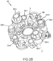
- the example shown in FIG. 2B may include a hybrid brake actuator 320 that comprises one or more electric motor actuators 322 (e.g., shown as EMA 322-1 and EMA 322-2).
- EMA 322 may be coupled to and/or attached to housing 326 in any suitable fashion.
- EMA 322 may be a module that removably couples to housing 326.
- EMA 322 may couple to housing 326 in any suitable orientation.
- a longitudinal centerline C-C' of EMA 322 may be generally perpendicular to a top surface D of housing 326.
- EMA 322 is operatively coupled to one or more hydraulic adjusters 324 (e.g. shown as hydraulic adjuster 324-1, hydraulic adjuster 324-2, hydraulic adjuster 324-3, and hydraulic adjuster 324-4). Each of EMA 322 and hydraulic adjuster 324 may be operatively installed on and/or contained on housing 326.
- hydraulic adjuster 324-1 e.g. shown as hydraulic adjuster 324-1, hydraulic adjuster 324-2, hydraulic adjuster 324-3, and hydraulic adjuster 324-4.
- Each of EMA 322 and hydraulic adjuster 324 may be operatively installed on and/or contained on housing 326.
- hybrid brake actuator 320 comprises a fluid reservoir 328 (e.g., shown as fluid reservoir 328-1 and fluid reservoir 328-2 in FIG. 2B ).
- Fluid reservoir 328 may be coupled to housing 326.
- Fluid reservoir 328 may also be in fluid communication with EMA 322, hydraulic adjustor 324, and/or housing 326.
- housing 326 may comprise various volumes, ports, channels, and/or fluid passages.
- the volumes, ports, channels, and/or fluid passages of housing 326 may be configured to conduct, transport, contain and/or store fluid (e.g., oil and/or hydraulic fluid).
- the volumes, ports, channels, and/or fluid passages may operatively couple, facilitate, and/or enable fluid communication between EMA 322, hydraulic adjuster 324, and/or fluid reservoir 328.
- EMA 322 may be electrically actuated to create a hydraulic pressure that may drive and/or actuate hydraulic adjuster 324.
- each hydraulic adjuster 324 comprises a piston 325 (e.g., shown as piston 325-1, piston 325-2, piston 325-3, piston 325-4, piston 325-5, and piston 325-6).
- piston 325 is housed in and deploys from hydraulic adjuster 324 in response to fluid being displaced by EMA 322.
- fluid from fluid reservoir 328 is displaced by EMA 322 to create hydraulic pressure.
- This hydraulic pressure is conducted to one or more hydraulic adjusters 324 causing piston 325 to extend, actuate, and/or deploy from hydraulic adjuster 324.
- the fluid displaced by EMA 322-1 may drive and/or actuate hydraulic adjuster 324-1 and hydraulic adjuster 324-2.
- the fluid displaced by EMA 322-2 may drive and/or actuate hydraulic adjuster 324-3 and hydraulic adjuster 324-4.
- fluid may be conducted from fluid reservoir 328 through one of more channels and/or ports in housing 326 to EMA 322, displaced by EMA 322 and conducted to one or more hydraulic adjusters 324 via the channels and/or ports of housing 326.
- housing 226 may define and/or comprise a compression chamber 223.
- EMA 222 may comprise a plunger 229 (e.g., a ram).
- Plunger 229 may be deployable into compression chamber 223.
- Compression chamber 223 is configured to receive and/or be in fluid communication with a fluid reservoir installed on the housing, and/or, although not shown, a fluid reservoir and/or volume defined within housing 226.
- Plunger 229 may be operatively coupled and/or capable of being driven by EMA 222.
- plunger 229 may be configured to change the volume of compression chamber 223 and/or displace fluid in compression chamber 223.
- compression chamber 223 further comprises one or more fluid ports 221 (e.g., shown as fluid port 221-1, and fluid port 221-2 in FIG. 4A ).
- One or more fluid ports 221 are configured to receive and exhaust fluid.
- fluid is conducted to a first fluid port 221 in response to a braking command.
- the fluid is displaced by actuator 222 and exhausted from compression chamber 223 through a fluid port 221 to a hydraulic adjuster 224.
- the displaced fluid causes piston 225 to further extend outward from hydraulic adjuster 224 to exert a force on the brake system and/or brake stack.
- hybrid brake actuator 220 may be configured as a redundant system.
- Hybrid brake actuator 220 may be configured to operate with only one EMA 222 or with more than one EMA 222 installed on housing 226.
- hybrid brake actuator 220 may be configured with two EMAs 222 (e.g., EMA 222-1 and EMA 222-2).
- EMA 222-1 and EMA 222-2 EMA 222-1 and EMA 222-2.
- a second EMA 222 may operate to provide a stopping force on the brake stack.
- the stopping force applied by hybrid brake actuator 220 on the brake system and/or brake stack may be reduced, but may be sufficient to slow and/or stop an aircraft during a taxi or landing event.
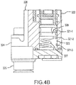
- FIG. 4B may include housing 326 that may define and/or comprise a compression chamber 323.
- EMA 322 may comprise a plunger 329 (e.g., a ram).
- Compression chamber 323 is configured to receive and/or be in fluid communication with a fluid reservoir (e.g., fluid reservoir 328, as shown in FIG. 2B ) installed on the housing, and/or, although not shown, a fluid reservoir and/or volume defined within housing 326.
- Plunger 329 may be operatively coupled and/or capable of being driven by EMA 322.
- plunger 329 may be configured to change the volume of compression chamber 323 and/or displace fluid in compression chamber 323.
- compression chamber 323 further comprises one or more fluid ports 321 (e.g., shown as fluid port 321-1, fluid port 321-2, and fluid port 321-3).
- One or more fluid ports 321 are configured to receive and exhaust fluid.
- fluid is conducted to a first fluid port 321 in response to a braking command.
- the fluid is displaced by actuator 322 and exhausted from compression chamber 323 through a second fluid port 321 to a hydraulic adjuster 324.
- the displaced fluid causes piston 325 to extend from hydraulic adjuster 324 to exert a force on the brake system and/or brake stack.
- hybrid brake actuator 320 may be configured as a redundant system.
- Hybrid brake actuator 320 may be configured to operate with only one EMA 322 or with more than one EMA 322 installed on housing 326.
- hybrid brake actuator 320 may be configured with two EMAs 322 (e.g., EMA 322-1 and EMA 322-2).
- EMA 322-1 and EMA 322-2 EMA 322-1 and EMA 322-2.
- a second EMA 322 may operate to provide a stopping force on the brake stack.
- the stopping force applied by hybrid brake actuator 320 on the brake system and/or brake stack may be reduced, but may be sufficient to slow and/or stop an aircraft during a taxi or landing event.
- hydraulic adjusters 224 and 324 may extend outward to accommodate the gap created by the worn brake stack.
- the fluid from the volume (or the fluid reservoir 328 as shown in FIG. 2B ) contained within housings 226 and 326 flows to and remains within the respective hydraulic adjuster 224 and 324 to maintain an extended position of the respective pistons 225 and 325.
- spring 327 may adjust and/or control the volume of compression chamber 323 to maintain a known volume of displacement.
- the volume of displacement of compression chamber 323 may be designed to provide a repeatable force during operation while allowing fluid to remain in hydraulic adjuster 324. This may allow piston 325 to remain extended to accommodate for wear in the brake stack.
- hybrid brake actuators 220 and 320 may be a modular design.
- various components of hybrid brake actuators 220 and 320 such as, for example, EMAs 222 and 322, hydraulic adjusters 224 and 324, and/or fluid reservoir 328 of FIGs 2B and 3B may be removable and/or replaceable.
- the various components may be threaded and/or screwed into the respective housings 226 and 326. This may improve the maintainability of hybrid brake actuators 220 and 320.
- hybrid brake actuators 220 and 320 may be scalable.
- hybrid brake actuators 220 and 320 may comprise any suitable number of respective EMAs 222 and 322s and/or hydraulic adjustors 224 and 324s to create an adequate stopping force for a brake system and/or aircraft.
- hybrid brake actuators 220 and 320 may be self-contained.
- hybrid brake actuators 220 and 320 may be a line replaceable unit.
- hybrid brake actuators 220 and 320 may be replaceable by removing a first hybrid brake actuator 220 and 320 and installing a second hybrid brake actuator 220 and 320.
- hybrid brake actuators 220 and 320 do not require additional installation steps that may be required of a typical hydraulic brake system such as, for example, bleeding and/or adjusting a typical hydraulic brake system.
- hybrid brake actuators 220 and 320 may be configured to work as a park brake when power is not being supplied by and/or to the aircraft.
- EMAs 222 and 322 may be commanded to displace fluid causing respective hydraulic adjusters 224 and 324 to apply a force to the brake stack and/or brake system.
- the respective hybrid brake actuator 220 and 320 may maintain a braking force, where the displaced volume of the respective compression chamber 223 and 323 is maintained with the respective EMA 222 and 322 in the stopped position.
- the braking force may also be maintained with a solenoid valve.
- hybrid brake actuators 220 and 320 may be installed on any suitable aircraft wheel. Similarly, hybrid brake actuators 220 and 320 may be adapted to any suitable hydraulic and/or electromechanical brake system.
Landscapes
- Engineering & Computer Science (AREA)
- Mechanical Engineering (AREA)
- General Engineering & Computer Science (AREA)
- Transportation (AREA)
- Aviation & Aerospace Engineering (AREA)
- Braking Arrangements (AREA)
- Braking Systems And Boosters (AREA)
- Regulating Braking Force (AREA)
Claims (10)
- Flugzeugbremsanlage, umfassend:einen Bremsstapel (112, 212); undeinen Hybridbremsaktuator (220), umfassend:ein Gehäuse (226);eine Druckkammer (223);ein in dem Gehäuse (226) definiertes Volumen;wobei die Druckkammer konfiguriert ist, um Fluid aus dem in dem Gehäuse definierten Volumen aufzunehmen;einen elektromechanischen Aktuator (EMA) (222-1, 222-2), der an das Gehäuse (226) gekoppelt ist, wobei der EMA (222-1, 222-2) konfiguriert ist, um einen Hydraulikdruck zu erzeugen und dadurch das Fluid aus der Druckkammer zu verdrängen;eine hydraulische Einstellvorrichtung (224-1 bis 224-6), die konfiguriert ist, um das Fluid über das Gehäuse (226) und als Reaktion darauf aufzunehmen, dass der EMA (222-1, 222-2) das Fluid verdrängt, wobei die hydraulische Einstellvorrichtung (224-1 bis 224-6) konfiguriert ist, um eine Kraft auf den Bremsstapel (112; 212) auszuüben;wobei die hydraulische Einstellvorrichtung (224-1 bis 224-6) einen Kolben (225-1 bis 225-6) umfasst, der konfiguriert ist, um sich von der hydraulischen Einstellvorrichtung (224-1 bis 224-6) zu erstrecken; und dadurch gekennzeichnet, dass:der Hybridbremsaktuator (220) an den Bremsstapel (112; 212) gekoppelt ist; undder EMA (222-1, 222-2) die Druckkammer (223) definiert, und ferner dadurch gekennzeichnet, dass die Druckkammer (223) einen oder mehrere Fluidanschlüsse (221) aufweist, die konfiguriert sind, um Fluid aufzunehmen und abzulassen, wobei Fluid zu dem oder einem ersten Fluidanschluss (221) als Reaktion auf eine elektronische Steuerung des EMA (222-1, 222-2) geleitet wird, das Fluid von dem EMA (222-1, 222-2) verdrängt und aus der Druckkammer (223) durch den oder einen zweiten Fluidanschluss zu der hydraulischen Einstellvorrichtung (224-1 bis 224-6) abgelassen wird, was dazu führt, dass sich der Kolben (225-1 bis 225-6) der Einstellvorrichtung von der hydraulischen Einstellvorrichtung (224-1 bis 224-6) erstreckt, um eine Kraft auf den Bremsstapel (112, 212) auszuüben,wobei eine Längsmittellinie A-A' des EMA (222) parallel zu der oberen Fläche (B) des Gehäuses (226) und parallel zu dem Bremsstapel (112, 212) verläuft;wobei der EMA (222) direkt an dem Gehäuse angebracht ist und wobei die Längsmittellinie A-A' des EMA (222) in Bezug auf eine Radialebene, die durch seine Verbindung zu dem Gehäuse hindurchgeht, tangential ausgerichtet ist.
- Flugzeugbremsanlage nach Anspruch 1, wobei der Hybridbremsaktuator ferner einen zweiten EMA (222-1, 222-2) umfasst.
- Flugzeugbremsanlage nach Anspruch 2, wobei der Hybridbremsaktuator ferner eine zweite hydraulische Einstellvorrichtung (224-1 bis 224-6) umfasst.
- Flugzeugbremsanlage nach Anspruch 3, wobei der EMA (222-1, 222-2) konfiguriert ist, um die hydraulische Einstellvorrichtung (224-1 bis 224-6) zu betätigen und der zweite EMA (222-1, 222-2) konfiguriert ist, um die zweite hydraulische Einstellvorrichtung (224-1 bis 224-6) zu betätigen.
- Flugzeugbremsanlage nach Anspruch 1, wobei der Hybridbremsaktuator ferner eine Vielzahl von hydraulischen Einstellvorrichtungen (224-1 bis 224-6) umfasst.
- Flugzeugbremsanlage nach Anspruch 1 oder 5, wobei der Hybridbremsaktuator ferner eine Vielzahl von EMAs (222-1, 222-2) umfasst.
- Flugzeugbremsanlage nach Anspruch 1; wobei
der Hybridbremsaktuator (120; 220) konfiguriert ist, um operativ an den Bremsstapel (112; 212) zu koppeln und diesen zu verdichten;
das Gehäuse (226) eine erste Druckkammer (223) und eine zweite Druckkammer (223) definiert,
der elektromechanische Aktuator einen ersten elektromechanischen Aktuator (EMA) (222-1, 222-2) umfasst, der an das Gehäuse (226) gekoppelt und konfiguriert ist, um ein Fluid in der ersten Druckkammer (223) als Reaktion auf einen Bremsbefehl zu verdrängen; wobei der Bremsaktuator ferner Folgendes umfasst:einen zweiten elektromechanischen Aktuator (222-1, 222-2), der an das Gehäuse (226) gekoppelt und konfiguriert ist, um das Fluid in der zweiten Druckkammer (223) als Reaktion auf den Bremsbefehl zu verdrängen,eine erste Vielzahl von hydraulischen Einstellvorrichtungen (224-1 bis 224-6), die konfiguriert sind, um das Fluid über das Gehäuse (226) und als Reaktion auf einen ersten Verdichtungstakt des ersten EMA (222-1, 222-2) aufzunehmen, undeine zweite Vielzahl von hydraulischen Einstellvorrichtungen (224-1 bis 224-6), die konfiguriert sind, um das Fluid über das Gehäuse (226) und als Reaktion auf einen zweiten Verdichtungstakt des zweiten EMA (222-1, 222-2) aufzunehmen. - Flugzeugbremsanlage nach Anspruch 7, wobei die Bremsanlage an einem Rad (110; 210) installiert werden soll.
- Flugzeugbremsanlage nach einem der Ansprüche 7 bis 8, wobei der zweite EMA (222-1, 222-2) dazu in der Lage ist, die zweite Vielzahl von hydraulischen Einstellvorrichtungen (224-1 bis 224-6) als Reaktion darauf zu betätigen, dass der erste EMA (222-1, 222-2) nicht funktioniert.
- Flugzeugbremsanlage nach einem der Ansprüche 7 bis 9, wobei der erste EMA (222-1, 222-2) einen ersten Fluidanschluss (221-1, 221-2), der Fluid von dem Gehäuse (226) aufnimmt und einen zweiten Fluidanschluss (221-1, 221-2) umfasst, der konfiguriert ist, um Fluid zu der ersten Vielzahl von hydraulischen Aktuatoren (224-1 bis 224-6) zu leiten.
Applications Claiming Priority (1)
| Application Number | Priority Date | Filing Date | Title |
|---|---|---|---|
| US14/071,875 US9254913B2 (en) | 2013-11-05 | 2013-11-05 | Hybrid braking system and apparatus |
Publications (3)
| Publication Number | Publication Date |
|---|---|
| EP2899424A2 EP2899424A2 (de) | 2015-07-29 |
| EP2899424A3 EP2899424A3 (de) | 2015-12-16 |
| EP2899424B1 true EP2899424B1 (de) | 2020-04-29 |
Family
ID=51845332
Family Applications (1)
| Application Number | Title | Priority Date | Filing Date |
|---|---|---|---|
| EP14191373.1A Active EP2899424B1 (de) | 2013-11-05 | 2014-10-31 | Flugzeugbremsanlage |
Country Status (2)
| Country | Link |
|---|---|
| US (1) | US9254913B2 (de) |
| EP (1) | EP2899424B1 (de) |
Families Citing this family (8)
| Publication number | Priority date | Publication date | Assignee | Title |
|---|---|---|---|---|
| CN106795930B (zh) * | 2014-10-23 | 2020-05-08 | 凯尔西-海耶斯公司 | 具有双独立致动器的电子驻车制动器 |
| US10458497B2 (en) * | 2015-06-29 | 2019-10-29 | Goodrich Corporation | Hybrid electric and hydraulic brake system |
| FR3082256B1 (fr) * | 2018-06-12 | 2020-05-29 | Airbus Helicopters | Systeme de freinage pour un train d'atterrissage d'aeronef a etrier avec plusieurs zone de pincement du disque de frein |
| CN109027064B (zh) * | 2018-07-17 | 2019-12-06 | 长沙学院 | 一种电气控制的制动装置 |
| US12179912B2 (en) * | 2020-09-29 | 2024-12-31 | Goodrich Corporation | Hybrid brake system |
| US12486050B2 (en) | 2022-02-10 | 2025-12-02 | Goodrich Corporation | Hybrid brake systems and methods |
| US11970263B2 (en) | 2022-02-10 | 2024-04-30 | Goodrich Corporation | Hybrid brake systems and methods for load cell calibration |
| US11999468B2 (en) | 2022-02-10 | 2024-06-04 | Goodrich Corporation | Hybrid brake systems and methods |
Family Cites Families (15)
| Publication number | Priority date | Publication date | Assignee | Title |
|---|---|---|---|---|
| US3473637A (en) * | 1968-08-09 | 1969-10-21 | Carborundum Co | Metal supported carbon friction disc |
| GB8801089D0 (en) * | 1988-01-19 | 1988-02-17 | Lucas Ind Plc | Brake |
| DE3907969A1 (de) * | 1989-03-11 | 1990-09-13 | Bosch Gmbh Robert | Hydraulische hochdruckpumpe fuer eine bremsanlage eines fahrzeugs |
| DE4010090A1 (de) * | 1990-03-29 | 1991-10-02 | Bosch Gmbh Robert | Hubkolbenpumpe |
| FR2673684B1 (fr) * | 1991-03-04 | 1993-07-09 | Poclain Hydraulics Sa | Ensemble d'un moteur a fluide sous pression a plusieurs cylindrees et d'un frein associe. |
| FR2675204B1 (fr) * | 1991-04-15 | 1993-08-06 | Poclain Hydraulics Sa | Ensemble d'un moteur hydraulique et d'un frein, et, compacteur en faisant application. |
| US6078118A (en) * | 1996-08-03 | 2000-06-20 | Itt Manufacturing Enterprises Inc. | Electric motor-pump assembly |
| US6360853B1 (en) * | 1996-10-18 | 2002-03-26 | The Boeing Company | Balanced brake assembly having coincident piston application |
| US6003640A (en) * | 1997-05-09 | 1999-12-21 | The B.F. Goodrich Company | Electronic braking system with brake wear measurement and running clearance adjustment |
| EP1195538A1 (de) * | 2000-10-09 | 2002-04-10 | GUSTAV MAGENWIRTH GmbH & Co. | Elektrisch ansteuerbare Bremsbestätigungsvorrichtung |
| JP2005096520A (ja) * | 2003-09-22 | 2005-04-14 | Advics:Kk | ブレーキ装置 |
| DE102004024060A1 (de) * | 2004-05-13 | 2005-12-08 | Continental Teves Ag & Co. Ohg | Elektrohydraulisches Aggregat für eine elektronische geregelte Bremsanlage |
| US20080135349A1 (en) * | 2004-06-04 | 2008-06-12 | Goodrich Corporation | Electric Brake for Aircraft |
| FR2970698B1 (fr) * | 2011-01-21 | 2013-10-04 | Messier Dowty Sa | Dispositif de freinage et d'entrainement en rotation d'une roue d'aeronef |
| US9669810B2 (en) * | 2012-01-10 | 2017-06-06 | Honeywell International Inc. | Brake assembly including independently activatable brake actuators |
-
2013
- 2013-11-05 US US14/071,875 patent/US9254913B2/en active Active
-
2014
- 2014-10-31 EP EP14191373.1A patent/EP2899424B1/de active Active
Non-Patent Citations (1)
| Title |
|---|
| None * |
Also Published As
| Publication number | Publication date |
|---|---|
| EP2899424A3 (de) | 2015-12-16 |
| EP2899424A2 (de) | 2015-07-29 |
| US20150122593A1 (en) | 2015-05-07 |
| US9254913B2 (en) | 2016-02-09 |
Similar Documents
| Publication | Publication Date | Title |
|---|---|---|
| EP2899424A2 (de) | Hybridbremssystem und Vorrichtung | |
| US11014543B2 (en) | Vehicle brake system having plunger power source | |
| US9174618B2 (en) | Brake and braking actuation units | |
| EP4119405B1 (de) | Elektrische hydraulische bremse | |
| KR20110120928A (ko) | 제어된 부스트를 갖는 유압 브레이크 시스템 | |
| US20200369246A1 (en) | Electrohydraulic vehicle power brake system for an autonomously driving land vehicle | |
| EP3160808B1 (de) | Automatisch gesteuertes bremssystem für fahrzeuge und verfahren zur betätigung und steuerung eines bremssystems für fahrzeuge | |
| US9216723B2 (en) | Method for controlling a wheel brake pressure in a hydraulic vehicle braking system | |
| WO2012058330A2 (en) | Hydraulic brake system with controlled boost | |
| WO2011097240A2 (en) | Hydraulic brake system with controlled boost | |
| KR102529506B1 (ko) | 차량용 제동 장치 | |
| US20220348176A1 (en) | Hydraulic unit for a service brake assembly of a hydraulic power-brake system | |
| EP3112232B1 (de) | Hybride elektrische und hydraulische bremsanlage | |
| ATE497901T1 (de) | Hauptbremszylinder für elektrohydraulisches bremssystem | |
| CN104340363A (zh) | 飞机起落架 | |
| KR20140069042A (ko) | 차량 브레이크 시스템용 브레이크 부스터 장치 및 차량 브레이크 시스템용 브레이크 부스터 장치의 제조 방법 | |
| EP2724046B1 (de) | Scheibenbremse | |
| KR20220170518A (ko) | 차량용 제동장치 | |
| EP3556652A1 (de) | Elektrohydrostatische bremssteuerung | |
| KR20190073495A (ko) | 차량 유압 브레이크 시스템 | |
| EP4308428B1 (de) | Bremssystem, brake-by-wire-modul und schaltvorrichtung | |
| CN103260971A (zh) | 用于车辆的压力传递装置、助力制动系统以及方法 | |
| EP3118075B1 (de) | Elektropneumatischer bremsaktuator | |
| US10933850B2 (en) | Automatic control braking system for vehicles | |
| EP3587198A1 (de) | Betätigungsmechanismus für eine mehrscheibenbremse |
Legal Events
| Date | Code | Title | Description |
|---|---|---|---|
| PUAI | Public reference made under article 153(3) epc to a published international application that has entered the european phase |
Free format text: ORIGINAL CODE: 0009012 |
|
| 17P | Request for examination filed |
Effective date: 20141031 |
|
| AK | Designated contracting states |
Kind code of ref document: A2 Designated state(s): AL AT BE BG CH CY CZ DE DK EE ES FI FR GB GR HR HU IE IS IT LI LT LU LV MC MK MT NL NO PL PT RO RS SE SI SK SM TR |
|
| AX | Request for extension of the european patent |
Extension state: BA ME |
|
| PUAL | Search report despatched |
Free format text: ORIGINAL CODE: 0009013 |
|
| AK | Designated contracting states |
Kind code of ref document: A3 Designated state(s): AL AT BE BG CH CY CZ DE DK EE ES FI FR GB GR HR HU IE IS IT LI LT LU LV MC MK MT NL NO PL PT RO RS SE SI SK SM TR |
|
| AX | Request for extension of the european patent |
Extension state: BA ME |
|
| RIC1 | Information provided on ipc code assigned before grant |
Ipc: B60T 13/58 20060101ALI20151106BHEP Ipc: F16D 65/18 20060101ALI20151106BHEP Ipc: F16D 65/12 20060101AFI20151106BHEP Ipc: B60T 17/22 20060101ALI20151106BHEP Ipc: B60T 13/74 20060101ALI20151106BHEP |
|
| 17P | Request for examination filed |
Effective date: 20160615 |
|
| RBV | Designated contracting states (corrected) |
Designated state(s): AL AT BE BG CH CY CZ DE DK EE ES FI FR GB GR HR HU IE IS IT LI LT LU LV MC MK MT NL NO PL PT RO RS SE SI SK SM TR |
|
| STAA | Information on the status of an ep patent application or granted ep patent |
Free format text: STATUS: EXAMINATION IS IN PROGRESS |
|
| 17Q | First examination report despatched |
Effective date: 20161122 |
|
| GRAP | Despatch of communication of intention to grant a patent |
Free format text: ORIGINAL CODE: EPIDOSNIGR1 |
|
| STAA | Information on the status of an ep patent application or granted ep patent |
Free format text: STATUS: GRANT OF PATENT IS INTENDED |
|
| INTG | Intention to grant announced |
Effective date: 20191217 |
|
| GRAS | Grant fee paid |
Free format text: ORIGINAL CODE: EPIDOSNIGR3 |
|
| GRAA | (expected) grant |
Free format text: ORIGINAL CODE: 0009210 |
|
| STAA | Information on the status of an ep patent application or granted ep patent |
Free format text: STATUS: THE PATENT HAS BEEN GRANTED |
|
| AK | Designated contracting states |
Kind code of ref document: B1 Designated state(s): AL AT BE BG CH CY CZ DE DK EE ES FI FR GB GR HR HU IE IS IT LI LT LU LV MC MK MT NL NO PL PT RO RS SE SI SK SM TR |
|
| REG | Reference to a national code |
Ref country code: GB Ref legal event code: FG4D |
|
| REG | Reference to a national code |
Ref country code: CH Ref legal event code: EP |
|
| REG | Reference to a national code |
Ref country code: AT Ref legal event code: REF Ref document number: 1263777 Country of ref document: AT Kind code of ref document: T Effective date: 20200515 |
|
| REG | Reference to a national code |
Ref country code: DE Ref legal event code: R096 Ref document number: 602014064433 Country of ref document: DE |
|
| REG | Reference to a national code |
Ref country code: IE Ref legal event code: FG4D |
|
| REG | Reference to a national code |
Ref country code: NL Ref legal event code: MP Effective date: 20200429 |
|
| REG | Reference to a national code |
Ref country code: LT Ref legal event code: MG4D |
|
| PG25 | Lapsed in a contracting state [announced via postgrant information from national office to epo] |
Ref country code: LT Free format text: LAPSE BECAUSE OF FAILURE TO SUBMIT A TRANSLATION OF THE DESCRIPTION OR TO PAY THE FEE WITHIN THE PRESCRIBED TIME-LIMIT Effective date: 20200429 Ref country code: GR Free format text: LAPSE BECAUSE OF FAILURE TO SUBMIT A TRANSLATION OF THE DESCRIPTION OR TO PAY THE FEE WITHIN THE PRESCRIBED TIME-LIMIT Effective date: 20200730 Ref country code: PT Free format text: LAPSE BECAUSE OF FAILURE TO SUBMIT A TRANSLATION OF THE DESCRIPTION OR TO PAY THE FEE WITHIN THE PRESCRIBED TIME-LIMIT Effective date: 20200831 Ref country code: IS Free format text: LAPSE BECAUSE OF FAILURE TO SUBMIT A TRANSLATION OF THE DESCRIPTION OR TO PAY THE FEE WITHIN THE PRESCRIBED TIME-LIMIT Effective date: 20200829 Ref country code: FI Free format text: LAPSE BECAUSE OF FAILURE TO SUBMIT A TRANSLATION OF THE DESCRIPTION OR TO PAY THE FEE WITHIN THE PRESCRIBED TIME-LIMIT Effective date: 20200429 Ref country code: NO Free format text: LAPSE BECAUSE OF FAILURE TO SUBMIT A TRANSLATION OF THE DESCRIPTION OR TO PAY THE FEE WITHIN THE PRESCRIBED TIME-LIMIT Effective date: 20200729 Ref country code: SE Free format text: LAPSE BECAUSE OF FAILURE TO SUBMIT A TRANSLATION OF THE DESCRIPTION OR TO PAY THE FEE WITHIN THE PRESCRIBED TIME-LIMIT Effective date: 20200429 |
|
| REG | Reference to a national code |
Ref country code: AT Ref legal event code: MK05 Ref document number: 1263777 Country of ref document: AT Kind code of ref document: T Effective date: 20200429 |
|
| PG25 | Lapsed in a contracting state [announced via postgrant information from national office to epo] |
Ref country code: BG Free format text: LAPSE BECAUSE OF FAILURE TO SUBMIT A TRANSLATION OF THE DESCRIPTION OR TO PAY THE FEE WITHIN THE PRESCRIBED TIME-LIMIT Effective date: 20200729 Ref country code: HR Free format text: LAPSE BECAUSE OF FAILURE TO SUBMIT A TRANSLATION OF THE DESCRIPTION OR TO PAY THE FEE WITHIN THE PRESCRIBED TIME-LIMIT Effective date: 20200429 Ref country code: LV Free format text: LAPSE BECAUSE OF FAILURE TO SUBMIT A TRANSLATION OF THE DESCRIPTION OR TO PAY THE FEE WITHIN THE PRESCRIBED TIME-LIMIT Effective date: 20200429 Ref country code: RS Free format text: LAPSE BECAUSE OF FAILURE TO SUBMIT A TRANSLATION OF THE DESCRIPTION OR TO PAY THE FEE WITHIN THE PRESCRIBED TIME-LIMIT Effective date: 20200429 |
|
| PG25 | Lapsed in a contracting state [announced via postgrant information from national office to epo] |
Ref country code: AL Free format text: LAPSE BECAUSE OF FAILURE TO SUBMIT A TRANSLATION OF THE DESCRIPTION OR TO PAY THE FEE WITHIN THE PRESCRIBED TIME-LIMIT Effective date: 20200429 Ref country code: NL Free format text: LAPSE BECAUSE OF FAILURE TO SUBMIT A TRANSLATION OF THE DESCRIPTION OR TO PAY THE FEE WITHIN THE PRESCRIBED TIME-LIMIT Effective date: 20200429 |
|
| PG25 | Lapsed in a contracting state [announced via postgrant information from national office to epo] |
Ref country code: AT Free format text: LAPSE BECAUSE OF FAILURE TO SUBMIT A TRANSLATION OF THE DESCRIPTION OR TO PAY THE FEE WITHIN THE PRESCRIBED TIME-LIMIT Effective date: 20200429 Ref country code: EE Free format text: LAPSE BECAUSE OF FAILURE TO SUBMIT A TRANSLATION OF THE DESCRIPTION OR TO PAY THE FEE WITHIN THE PRESCRIBED TIME-LIMIT Effective date: 20200429 Ref country code: DK Free format text: LAPSE BECAUSE OF FAILURE TO SUBMIT A TRANSLATION OF THE DESCRIPTION OR TO PAY THE FEE WITHIN THE PRESCRIBED TIME-LIMIT Effective date: 20200429 Ref country code: CZ Free format text: LAPSE BECAUSE OF FAILURE TO SUBMIT A TRANSLATION OF THE DESCRIPTION OR TO PAY THE FEE WITHIN THE PRESCRIBED TIME-LIMIT Effective date: 20200429 Ref country code: IT Free format text: LAPSE BECAUSE OF FAILURE TO SUBMIT A TRANSLATION OF THE DESCRIPTION OR TO PAY THE FEE WITHIN THE PRESCRIBED TIME-LIMIT Effective date: 20200429 Ref country code: ES Free format text: LAPSE BECAUSE OF FAILURE TO SUBMIT A TRANSLATION OF THE DESCRIPTION OR TO PAY THE FEE WITHIN THE PRESCRIBED TIME-LIMIT Effective date: 20200429 Ref country code: SM Free format text: LAPSE BECAUSE OF FAILURE TO SUBMIT A TRANSLATION OF THE DESCRIPTION OR TO PAY THE FEE WITHIN THE PRESCRIBED TIME-LIMIT Effective date: 20200429 Ref country code: RO Free format text: LAPSE BECAUSE OF FAILURE TO SUBMIT A TRANSLATION OF THE DESCRIPTION OR TO PAY THE FEE WITHIN THE PRESCRIBED TIME-LIMIT Effective date: 20200429 |
|
| REG | Reference to a national code |
Ref country code: DE Ref legal event code: R097 Ref document number: 602014064433 Country of ref document: DE |
|
| PG25 | Lapsed in a contracting state [announced via postgrant information from national office to epo] |
Ref country code: PL Free format text: LAPSE BECAUSE OF FAILURE TO SUBMIT A TRANSLATION OF THE DESCRIPTION OR TO PAY THE FEE WITHIN THE PRESCRIBED TIME-LIMIT Effective date: 20200429 Ref country code: SK Free format text: LAPSE BECAUSE OF FAILURE TO SUBMIT A TRANSLATION OF THE DESCRIPTION OR TO PAY THE FEE WITHIN THE PRESCRIBED TIME-LIMIT Effective date: 20200429 |
|
| PLBE | No opposition filed within time limit |
Free format text: ORIGINAL CODE: 0009261 |
|
| STAA | Information on the status of an ep patent application or granted ep patent |
Free format text: STATUS: NO OPPOSITION FILED WITHIN TIME LIMIT |
|
| 26N | No opposition filed |
Effective date: 20210201 |
|
| REG | Reference to a national code |
Ref country code: DE Ref legal event code: R119 Ref document number: 602014064433 Country of ref document: DE |
|
| PG25 | Lapsed in a contracting state [announced via postgrant information from national office to epo] |
Ref country code: SI Free format text: LAPSE BECAUSE OF FAILURE TO SUBMIT A TRANSLATION OF THE DESCRIPTION OR TO PAY THE FEE WITHIN THE PRESCRIBED TIME-LIMIT Effective date: 20200429 |
|
| REG | Reference to a national code |
Ref country code: CH Ref legal event code: PL |
|
| PG25 | Lapsed in a contracting state [announced via postgrant information from national office to epo] |
Ref country code: LU Free format text: LAPSE BECAUSE OF NON-PAYMENT OF DUE FEES Effective date: 20201031 Ref country code: MC Free format text: LAPSE BECAUSE OF FAILURE TO SUBMIT A TRANSLATION OF THE DESCRIPTION OR TO PAY THE FEE WITHIN THE PRESCRIBED TIME-LIMIT Effective date: 20200429 |
|
| REG | Reference to a national code |
Ref country code: BE Ref legal event code: MM Effective date: 20201031 |
|
| PG25 | Lapsed in a contracting state [announced via postgrant information from national office to epo] |
Ref country code: DE Free format text: LAPSE BECAUSE OF NON-PAYMENT OF DUE FEES Effective date: 20210501 |
|
| PG25 | Lapsed in a contracting state [announced via postgrant information from national office to epo] |
Ref country code: LI Free format text: LAPSE BECAUSE OF NON-PAYMENT OF DUE FEES Effective date: 20201031 Ref country code: BE Free format text: LAPSE BECAUSE OF NON-PAYMENT OF DUE FEES Effective date: 20201031 Ref country code: CH Free format text: LAPSE BECAUSE OF NON-PAYMENT OF DUE FEES Effective date: 20201031 |
|
| PG25 | Lapsed in a contracting state [announced via postgrant information from national office to epo] |
Ref country code: IE Free format text: LAPSE BECAUSE OF NON-PAYMENT OF DUE FEES Effective date: 20201031 |
|
| PG25 | Lapsed in a contracting state [announced via postgrant information from national office to epo] |
Ref country code: TR Free format text: LAPSE BECAUSE OF FAILURE TO SUBMIT A TRANSLATION OF THE DESCRIPTION OR TO PAY THE FEE WITHIN THE PRESCRIBED TIME-LIMIT Effective date: 20200429 Ref country code: MT Free format text: LAPSE BECAUSE OF FAILURE TO SUBMIT A TRANSLATION OF THE DESCRIPTION OR TO PAY THE FEE WITHIN THE PRESCRIBED TIME-LIMIT Effective date: 20200429 Ref country code: CY Free format text: LAPSE BECAUSE OF FAILURE TO SUBMIT A TRANSLATION OF THE DESCRIPTION OR TO PAY THE FEE WITHIN THE PRESCRIBED TIME-LIMIT Effective date: 20200429 |
|
| PG25 | Lapsed in a contracting state [announced via postgrant information from national office to epo] |
Ref country code: MK Free format text: LAPSE BECAUSE OF FAILURE TO SUBMIT A TRANSLATION OF THE DESCRIPTION OR TO PAY THE FEE WITHIN THE PRESCRIBED TIME-LIMIT Effective date: 20200429 |
|
| P01 | Opt-out of the competence of the unified patent court (upc) registered |
Effective date: 20230522 |
|
| PGFP | Annual fee paid to national office [announced via postgrant information from national office to epo] |
Ref country code: GB Payment date: 20250923 Year of fee payment: 12 |
|
| PGFP | Annual fee paid to national office [announced via postgrant information from national office to epo] |
Ref country code: FR Payment date: 20250923 Year of fee payment: 12 |