EP2899414A1 - Palier amorti d'arbre de rotor - Google Patents
Palier amorti d'arbre de rotor Download PDFInfo
- Publication number
- EP2899414A1 EP2899414A1 EP14152298.7A EP14152298A EP2899414A1 EP 2899414 A1 EP2899414 A1 EP 2899414A1 EP 14152298 A EP14152298 A EP 14152298A EP 2899414 A1 EP2899414 A1 EP 2899414A1
- Authority
- EP
- European Patent Office
- Prior art keywords
- rotor shaft
- electric machine
- damping element
- damping
- unit
- Prior art date
- Legal status (The legal status is an assumption and is not a legal conclusion. Google has not performed a legal analysis and makes no representation as to the accuracy of the status listed.)
- Withdrawn
Links
Images

Classifications
-
- H—ELECTRICITY
- H02—GENERATION; CONVERSION OR DISTRIBUTION OF ELECTRIC POWER
- H02P—CONTROL OR REGULATION OF ELECTRIC MOTORS, ELECTRIC GENERATORS OR DYNAMO-ELECTRIC CONVERTERS; CONTROLLING TRANSFORMERS, REACTORS OR CHOKE COILS
- H02P29/00—Arrangements for regulating or controlling electric motors, appropriate for both AC and DC motors
- H02P29/50—Reduction of harmonics
-
- F—MECHANICAL ENGINEERING; LIGHTING; HEATING; WEAPONS; BLASTING
- F16—ENGINEERING ELEMENTS AND UNITS; GENERAL MEASURES FOR PRODUCING AND MAINTAINING EFFECTIVE FUNCTIONING OF MACHINES OR INSTALLATIONS; THERMAL INSULATION IN GENERAL
- F16C—SHAFTS; FLEXIBLE SHAFTS; ELEMENTS OR CRANKSHAFT MECHANISMS; ROTARY BODIES OTHER THAN GEARING ELEMENTS; BEARINGS
- F16C27/00—Elastic or yielding bearings or bearing supports, for exclusively rotary movement
- F16C27/04—Ball or roller bearings, e.g. with resilient rolling bodies
-
- F—MECHANICAL ENGINEERING; LIGHTING; HEATING; WEAPONS; BLASTING
- F16—ENGINEERING ELEMENTS AND UNITS; GENERAL MEASURES FOR PRODUCING AND MAINTAINING EFFECTIVE FUNCTIONING OF MACHINES OR INSTALLATIONS; THERMAL INSULATION IN GENERAL
- F16C—SHAFTS; FLEXIBLE SHAFTS; ELEMENTS OR CRANKSHAFT MECHANISMS; ROTARY BODIES OTHER THAN GEARING ELEMENTS; BEARINGS
- F16C27/00—Elastic or yielding bearings or bearing supports, for exclusively rotary movement
- F16C27/02—Sliding-contact bearings
-
- H—ELECTRICITY
- H02—GENERATION; CONVERSION OR DISTRIBUTION OF ELECTRIC POWER
- H02K—DYNAMO-ELECTRIC MACHINES
- H02K11/00—Structural association of dynamo-electric machines with electric components or with devices for shielding, monitoring or protection
- H02K11/20—Structural association of dynamo-electric machines with electric components or with devices for shielding, monitoring or protection for measuring, monitoring, testing, protecting or switching
-
- H—ELECTRICITY
- H02—GENERATION; CONVERSION OR DISTRIBUTION OF ELECTRIC POWER
- H02K—DYNAMO-ELECTRIC MACHINES
- H02K5/00—Casings; Enclosures; Supports
- H02K5/04—Casings or enclosures characterised by the shape, form or construction thereof
- H02K5/16—Means for supporting bearings, e.g. insulating supports or means for fitting bearings in the bearing-shields
- H02K5/161—Means for supporting bearings, e.g. insulating supports or means for fitting bearings in the bearing-shields radially supporting the rotary shaft at both ends of the rotor
-
- H—ELECTRICITY
- H02—GENERATION; CONVERSION OR DISTRIBUTION OF ELECTRIC POWER
- H02K—DYNAMO-ELECTRIC MACHINES
- H02K5/00—Casings; Enclosures; Supports
- H02K5/24—Casings; Enclosures; Supports specially adapted for suppression or reduction of noise or vibrations
-
- H—ELECTRICITY
- H02—GENERATION; CONVERSION OR DISTRIBUTION OF ELECTRIC POWER
- H02K—DYNAMO-ELECTRIC MACHINES
- H02K7/00—Arrangements for handling mechanical energy structurally associated with dynamo-electric machines, e.g. structural association with mechanical driving motors or auxiliary dynamo-electric machines
- H02K7/08—Structural association with bearings
-
- F—MECHANICAL ENGINEERING; LIGHTING; HEATING; WEAPONS; BLASTING
- F16—ENGINEERING ELEMENTS AND UNITS; GENERAL MEASURES FOR PRODUCING AND MAINTAINING EFFECTIVE FUNCTIONING OF MACHINES OR INSTALLATIONS; THERMAL INSULATION IN GENERAL
- F16C—SHAFTS; FLEXIBLE SHAFTS; ELEMENTS OR CRANKSHAFT MECHANISMS; ROTARY BODIES OTHER THAN GEARING ELEMENTS; BEARINGS
- F16C2380/00—Electrical apparatus
- F16C2380/26—Dynamo-electric machines or combinations therewith, e.g. electro-motors and generators
-
- H—ELECTRICITY
- H02—GENERATION; CONVERSION OR DISTRIBUTION OF ELECTRIC POWER
- H02K—DYNAMO-ELECTRIC MACHINES
- H02K2213/00—Specific aspects, not otherwise provided for and not covered by codes H02K2201/00 - H02K2211/00
- H02K2213/09—Machines characterised by the presence of elements which are subject to variation, e.g. adjustable bearings, reconfigurable windings, variable pitch ventilators
Definitions
- the invention relates to an arrangement for damped storage of a rotor shaft of an electric machine. Furthermore, the invention relates to an electric machine with a rotor shaft and at least one such arrangement. In addition, the invention relates to a system for damped storage of an electrical machine. Furthermore, the invention relates to a method for damped storage of a rotor shaft of such an electric machine. Finally, the invention relates to a method for operating such an electric machine.
- Bearings of rotors can be embodied, for example, as hydrodynamic plain bearings, hydrostatic plain bearings, rolling bearings, active and passive magnetic bearings or air bearings.
- subcritical rotors and supercritical rotors. If the first natural frequency of the system is above its operating speed, it is called a subcritical rotor. Lying natural frequencies below the operating speed is a supercritical rotor. In this case, one needs an external damping of a certain size at the bearings in order to pass through the natural frequencies up to the operating speed or to operate the rotor in its natural frequency. Furthermore, it is possible that as a result of internal damping of the rotor or by the carrier medium of plain bearings caused an instability of the rotor system. To prevent this, an external damping in the bearings is also required.
- damping in the bearings is not sufficient, there are various ways to generate additional damping, eg. B. rubber elements below the camp or Quetschöldämpfer below the camp or directly on the rotor.
- a bearing ring which has an inner and an outer bearing shell, which are arranged at a radial distance from one another and in the thus formed space a two bearing shells rotatably connecting element is arranged, which is designed as a wire mesh.
- An axial roller bearing which comprises an upper ring, a lower ring and between the rings balls, wherein for the rings, a pressed band of metal fibers is used and wherein the rings are covered with plastic shells.
- the invention has for its object to provide an alternative to the damped bearings of a rotor shaft.
- the arrangement has a bearing unit, which is arranged between the rotor shaft and a housing of the electric machine, and a damping element, which is arranged between the bearing unit and the rotor shaft or between the bearing unit and the housing, wherein the damping element comprises a mesh of metal wire.
- the damping element may for example be made of pressed metal wire and is in particular mounted around the bearing point, so that the damping element is arranged radially on the outside of the bearing unit and enclosing the bearing unit. From radially inward to radially outward are thus first the rotor shaft, then the bearing unit, then arranged the damping element and finally the housing of the electrical machine.
- the damping element can be arranged radially on the outside of the rotor shaft and enclose the rotor shaft. Accordingly, the rotor shaft, then the damping element, then the bearing unit and finally the housing of the electric machine are arranged from radially inward to radially outward first. Consequently, the bearing unit, which provides the rotational degree of freedom for the rotor shaft, envelops the damping element, so that the actual bearing point is located on the outside of the damping element.
- the proposed solution can, as described above, be used for the damped storage of radial forces. Also, a damped storage of axial forces can be accomplished with the proposed solution by the damping element and the bearing unit are arranged in the axial direction between the rotor shaft and a part of the rotor shaft and the housing. In addition, mixed forms are possible, by means of which a superposition of radial forces and axial forces absorbed damped.
- the operative connection of the force element with the sensor element can be realized, for example, by a direct data exchange by means of a wire connection or a wireless connection between the sensor element and the force element. It is also conceivable that the operative connection is designed indirectly, for example by data of the sensor element finally cause a certain action of the force element via the arithmetic unit and the inverter unit.
- the proposed method for damped bearing of the rotor shaft provides that the spring constant of the damping element, the damping constant of the damping element and / or the biasing force acting on the damping element is detected, for which purpose the sensor element is used. Furthermore, it is provided that the damping element is controllably biased, for which purpose the force element and, for example, a computing unit are used.
- the biasing force can be configured as a compressive or tensile force.
- a combination of different compressive or tensile forces can be realized, which act in particular in different directions acting on the damping element or at different points on the damping element. In this way, it is possible to achieve anisotropy of the damping properties, as a result of which oscillation modes acting in different directions can be damped to different degrees.
- the senor element imparts test pulses for determining the natural frequencies and determines the response of the system to the test pulses.
- the converter unit is provided in particular for supplying the stator of the electric machine with electrical energy and acts on the stator in accordance with the specifications of the computing unit.
- the arithmetic unit can be embodied, for example, as a microcontroller, CPU or the like and, in particular, integrated into the sensor element, the force element or the converter unit. Alternatively, the arithmetic unit can be integrated in a higher-level controller or the converter unit.
- the bearing unit is designed as a rolling bearing or as a plain bearing.
- Rolling bearings usually have no or very little own damping.
- the additional external damping of the proposed arrangement makes it possible to operate a rotor system supercritically even when such types of bearings are used, which generate very little self-damping.
- This allows, for example, the storage of a comparatively powerful electric motor with a shaft height of 450 mm and more to accomplish by means of the proposed arrangement with a rolling bearing.
- Such large and powerful electric machines are usually operated supercritically, so that the operating speed is greater than at least one natural frequency of the electric machine.
- the use of a rolling bearing offers several advantages, such as a comparatively simple installation and maintenance. This is the disadvantage of Rolling the very low attenuation by the damping element more than balanced, so that large electrical machines can be operated supercritically thanks to the proposed arrangement with a rolling bearing.
- the damping element has an inner ring and an outer ring, wherein the braid of metal wire between the inner ring and the outer ring is arranged.
- the braid of metal wire is securely bordered and fixed in position. Furthermore, a particularly easy maintenance is possible because a worn metal mesh can be easily replaced. This is achieved, for example, in that only one of the rings has to be removed to replace the metal braid and then re-attach the removed ring.
- the two rings can also be used for biasing the damping element by exerting on one of the rings, for example, a force in the one axial direction and on the other ring a force in the opposite axial direction.
- the inner ring and / or the outer ring has an L-shaped cross section.
- the metal mesh can be easily protected from adverse external influences, such as dust and other impurities.
- both the inner ring and the outer ring have an L-shaped cross-section and the two L-shaped cross sections are arranged such that a rectangular cross-section is formed, a particularly reliable protection of the metal braid is achievable.
- a corresponding arrangement of the shorter web of the L-shaped cross section serve to fix the metal mesh in the axial direction, whereby a reliable adjustment of a biasing force of the damping element is made possible.
- the inner ring and / or the outer ring has a wedge-shaped cross-section.
- a biasing force acting on the damping element in the axial direction can be used to exert on the bearing unit and / or the rotor shaft a modified biasing force, which has a component both in the axial direction and in the radial direction.
- This can be particularly advantageous in electric machines, in which forces acting in the axial and radial directions are to be stored reliably and in appropriate directions pronounced vibrations are to be reliably damped.
- one of the two rings has an L-shaped cross section and the other ring has a wedge-shaped cross section.
- the damping element has a spring constant and an attenuation constant, wherein the damping element can be prestressed in such a way that the damping element is a predefinable Has spring constant and / or a predetermined damping constant.
- the stiffness of the damping element depends inter alia on the biasing force applied to the metal mesh. About this force, the stiffness of the damping element can be adjusted.
- the predefinable spring constant and / or the predefinable damping constant can be determined in advance, for example by performing corresponding calculations or tests.
- the predefinable spring constant and / or the predefinable damping constant is selected such that the natural frequencies of the rotor shaft or the electric machine are shifted toward higher frequencies.
- the rotor shaft By exerting a biasing force, which leads to one of the predefinable spring constant corresponding spring constant and / or which corresponds to one of the predefinable damping constant damping constant, the rotor shaft can in particular always be operated subcritically, whereby the stability of the rotor shaft and the electric machine is increased.
- the damping element can also be designed so pretensioned that the entire arrangement for damped bearings has a predeterminable spring constant and / or a predefinable damping constant.
- a sensor element is provided by means of which the spring constant of the damping element, the damping constant of the damping element and / or acting on the damping element biasing force can be detected, wherein a force element is provided, which is operatively connected to the sensor element and means in which the damping element is controllably prestressed.
- the sensor element initially detects at least one input variable, which is, for example, the damping constant of the damping element.
- the input variable is compared with a desired value, for example, the predefinable damping constant, wherein the comparison can be made in particular by the above-explained computing unit.
- the force element is acted upon in particular by means of a converter unit connected to the computing unit such that the damping element has the desired desired size.
- the arithmetic unit for this purpose can determine such a magnitude of a biasing force, which must exert the force unit on the damping element, so that the desired target size is achieved.
- the sensor element may be configured such that the spring constant of the entire arrangement, the damping constant of the entire arrangement for damped storage and / or the biasing force acting on the entire arrangement for damped storage can be detected.
- the force element has at least one bolt, which is passed through the damping element or the mesh of metal wire, wherein at the two axial ends of the respective bolt, a device is provided by means of which a compressive or tensile force on the damping element or the braid can be exercised from metal wire.
- the sensor element and the force element are connected in particular as for the method explained above for operating the electrical machine via the arithmetic unit and the converter unit.
- a direct connection of the sensor element may be provided with the force element.
- the damping element can be prestressed such that the rotor shaft and / or the electric machine can be operated supercritically.
- the damping element is biased in a supercritical operation of the rotor shaft or the electric machine such that the damping constant of the damping element is high enough for always safe operation.
- the damping element has at least one corresponding, predefinable damping constant.
- the biasing force may, for example, be chosen such that those natural frequencies which are closest to the operating frequency of the rotor shaft or the electric machine are far enough away from the operating frequency.
- a natural frequency which is only slightly below the operating frequency, be further shifted down as long as the existing during the passage of this natural frequency damping by means of the damping element can be at least temporarily large enough.
- the damping element can be prestressed such that natural frequencies of the damped rotor shaft are greater than an operating frequency of the electric machine.
- the rotor shaft or the electric machine can be reliably operated subcritical, resulting in the stability of the system and in particular increases the life of the storage unit.
- the arrangement comprises a shield element, which is arranged between the rotor shaft and the housing, wherein the bearing unit and the damping element between the rotor shaft and the shield member or between the housing and the shield element are arranged.
- the shield element may in particular be designed such that it at least partially surrounds the bearing unit and the damping element.
- the shield element can be designed annular and have an L-shaped or a U-shaped cross section and be arranged such that the unit of the bearing unit and the damping element is enclosed in the radial direction to the housing or the rotor shaft of the shield element. Furthermore, with such a cross-section of the shield element, an axial enclosure in one direction or in both directions can be achieved, whereby on the one hand the stability of the entire arrangement for damped storage is increased and on the other hand the assembly and maintenance of the entire arrangement is facilitated.
- the shield element does not touch the housing and the rotor shaft at the same time.
- an electric machine with the arrangement proposed above for damped bearing of a rotor shaft can have a shaft height of at least 350 mm, in particular more than 450 mm.
- the arrangement can be used in electrical machines, which with an electric Power of at least 250 kW, in particular more than 1 MW, are operable.
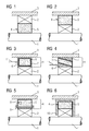
- FIG. 1 shows a first embodiment of the inventive arrangement for damped storage of a rotor shaft 1 of an electric machine.
- the arrangement is arranged between a housing 3 of an electric machine and the rotor shaft 1 of the electric machine and has a bearing unit 2 and a damping element 4.
- the damping element 4 on a braid of metal wire 5.
- the damping element 4 is arranged radially further inside than the bearing element 2.
- the bearing unit 2 may be designed, for example, as a rolling bearing or as a sliding bearing.
- FIG. 2 shows a second embodiment of the inventive arrangement.
- the arrangement for damped storage is designed such that the bearing element 2 is arranged radially further inwardly than the damping element 4.
- FIG. 3 shows a third embodiment of the inventive arrangement.
- the arrangement for damped bearing according to the third embodiment is similar to that of the second embodiment, wherein the damping element 4 has an inner ring 6 and an outer ring 7.
- the mesh of metal wire 5 of the damping element 4 is disposed between the inner ring 6 and the outer ring 7.
- the two rings 6 and 7 each have an L-shaped cross-section and, viewed together in cross-section, in particular form an approximately rectangular enclosure for the metal wire mesh 5.
- a biasing force in the axial direction can be applied to the inner ring 6, as indicated by the arrow with the reference numeral 11.
- Such a border of the braid of metal wire 5 based on the inner ring 6 and the outer ring 7 may also be provided in the arrangement for damped storage according to the first embodiment.
- FIG. 4 shows a fourth embodiment of the arrangement according to the invention.
- the inner ring 6 and the outer ring 7 each have a wedge-shaped cross-section.
- the wedge of the inner ring 6 tapers in the one axial direction
- the wedge of the outer ring 7 tapers in the other axial direction.
- the braid of metal wire 5 between the two rings 6 and 7 is arranged.
- a biasing force in the axial direction can be applied to the inner ring 6, as indicated by the arrow with the reference numeral 11.
- Such a border of the braid of metal wire 5 based on the inner ring 6 and the outer ring 7 may also be provided in the arrangement for damped storage according to the first embodiment.
- FIG. 5 shows a fifth embodiment of the arrangement according to the invention.
- the arrangement for damped bearing according to the fifth embodiment is similar to that of the second embodiment, wherein additionally a sensor element 8 and a force element 9 are provided.
- a sensor element 8 and a force element 9 are provided.
- the sensor element 8 By means of the sensor element 8, a spring constant of the damping element 4, a damping constant of the damping element 4 and / or acting on the damping element 4 biasing force can be detected.
- the sensor element 8 is arranged for this purpose in the damping element 4 or on the braid of metal wire 5.
- the sensor element 8 is operatively connected to the force element 9, by means of which the damping element 4 is controllably biased.
- the force element 9 at least one bolt, which is passed through the damping element 4 and the braid of metal wire 5, wherein at the two axial ends of the respective bolt a device is provided by means of which a compressive or tensile force on the damping element 4th or the mesh of metal wire 5 can be exercised.
- the controllable bias of the damping element 4 by means of the force element 9 is in particular realized in that the sensor element 8 detects at least one input variable, which is for example the damping constant of the damping element 8.
- the input variable is compared with a desired value, for example a predefinable damping constant, wherein the comparison can be made in particular by a computing unit of a controller. Based on this comparison, the force element 9 is acted upon such that the damping element 4 has the desired desired size.
- the arithmetic unit can determine for this purpose a magnitude of a pretensioning force which the force unit 9 has to exert on the damping element 4, so that the desired setpoint value is achieved.
- This controllable bias of the damping element 4 can be used in particular in the arrangements for damped storage according to the first, the third or the fourth embodiment.
- FIG. 6 shows a sixth embodiment of the arrangement according to the invention.
- the arrangement for damped bearing according to the sixth embodiment is similar to that of the second embodiment, wherein additionally a shield member 10 is provided, which is arranged between the rotor shaft 1 and the housing 3.
- the bearing unit 2 and the damping element 4 are arranged between the rotor shaft 1 and the shield element 10.
- the shield member 10 has a U-shaped cross-section, wherein the opening of the U-shape can be aligned as in the present embodiment to the rotor shaft.
- the damping element 4 and the bearing unit 2 are at least partially disposed within the U-shape, so that the shield member 10, the damping element 4 and the storage unit 2 einhaust partially.
- the bearing unit 2 and the damping element 4 may be arranged between the housing 3 and the shield element 10. If the shield element 10 has a U-shaped cross-section, then the opening of the U-shape can be aligned with the housing.
- the shield element 10 does not simultaneously contact the housing 3 and the rotor shaft 1.
- the shield element 10 can also be used in particular in the arrangements for damped bearing according to the first, the third, the fourth or the fifth embodiment.
- FIG. 7 shows an embodiment of the system for carrying out the method for operating an electric machine.
- the system has an arrangement for dampably supporting the rotor shaft 1, which is similar to that of the fifth embodiment. Furthermore, the system has a computer unit 14 and a converter unit 15 connected to the computer unit 14.
- the electric machine has a rotor 12, which is rotatably connected to the rotor shaft 1, and a stator 13, which can be acted upon by the converter unit 15 with electric current.
- the sensor element 8 natural frequencies of the damped rotor shaft 1 and / or the electric machine can be determined, wherein the natural frequencies of the sensor element 8 can be transmitted to the connected to the sensor element 8 arithmetic unit 14.
- the computing unit 14 is designed to determine setpoint values for the force element 9 and to transmit them to the converter unit 15.
- the power element 9 can be acted upon by the converter unit 15 in accordance with the desired values such that the rotor shaft 1 and / or the electric machine can be operated supercritically or such that the natural frequencies of the damped rotor shaft 1 are greater than an operating frequency of the electric machine. In the event that the rotor shaft 1 and / or the electric machine is operated supercritically, the natural frequencies are traversable until reaching the operating frequency or standstill with a maximum, temporal speed change.
- the arrangement for damped bearing according to the fifth embodiment is similar to that of the second embodiment, wherein
- the invention relates to an arrangement for damped storage of a rotor shaft of an electric machine. Furthermore, the invention relates to an electrical machine with a rotor shaft and at least one such arrangement. In addition, the invention relates to a system for damped storage of an electrical machine. Furthermore, the invention relates to a method for damped storage of a rotor shaft of such an electric machine. Finally, the invention relates to a method for operating such an electric machine.
- the arrangement comprises a bearing unit, which is arranged between the rotor shaft and a housing of the electric machine, and a damping element, which is arranged between the bearing unit and the rotor shaft or between the bearing unit and the housing is arranged, wherein the damping element comprises a mesh of metal wire.
- the electrical machine has at least one such arrangement.
Priority Applications (5)
| Application Number | Priority Date | Filing Date | Title |
|---|---|---|---|
| EP14152298.7A EP2899414A1 (fr) | 2014-01-23 | 2014-01-23 | Palier amorti d'arbre de rotor |
| PCT/EP2015/050535 WO2015110322A1 (fr) | 2014-01-23 | 2015-01-14 | Montage sur palier amorti d'un arbre de rotor |
| CN201580004136.2A CN105899824B (zh) | 2014-01-23 | 2015-01-14 | 转子轴的减震支承 |
| EP15700983.8A EP3063423B1 (fr) | 2014-01-23 | 2015-01-14 | Palier amorti d'arbre de rotor |
| US15/113,353 US10050579B2 (en) | 2014-01-23 | 2015-01-14 | Damped bearing of a rotor shaft |
Applications Claiming Priority (1)
| Application Number | Priority Date | Filing Date | Title |
|---|---|---|---|
| EP14152298.7A EP2899414A1 (fr) | 2014-01-23 | 2014-01-23 | Palier amorti d'arbre de rotor |
Publications (1)
| Publication Number | Publication Date |
|---|---|
| EP2899414A1 true EP2899414A1 (fr) | 2015-07-29 |
Family
ID=49999764
Family Applications (2)
| Application Number | Title | Priority Date | Filing Date |
|---|---|---|---|
| EP14152298.7A Withdrawn EP2899414A1 (fr) | 2014-01-23 | 2014-01-23 | Palier amorti d'arbre de rotor |
| EP15700983.8A Active EP3063423B1 (fr) | 2014-01-23 | 2015-01-14 | Palier amorti d'arbre de rotor |
Family Applications After (1)
| Application Number | Title | Priority Date | Filing Date |
|---|---|---|---|
| EP15700983.8A Active EP3063423B1 (fr) | 2014-01-23 | 2015-01-14 | Palier amorti d'arbre de rotor |
Country Status (4)
| Country | Link |
|---|---|
| US (1) | US10050579B2 (fr) |
| EP (2) | EP2899414A1 (fr) |
| CN (1) | CN105899824B (fr) |
| WO (1) | WO2015110322A1 (fr) |
Cited By (11)
| Publication number | Priority date | Publication date | Assignee | Title |
|---|---|---|---|---|
| WO2015164621A1 (fr) | 2014-04-23 | 2015-10-29 | Gkn Driveline North America, Inc. | Composant de train cinématique d'automobile amorti |
| DE102016205164A1 (de) * | 2016-03-30 | 2017-10-05 | Robert Bosch Gmbh | Elektrische Maschine mit einem am Stator angebrachten Lagerschild |
| EP3293864A1 (fr) * | 2016-09-09 | 2018-03-14 | Lg Electronics Inc. | Palier à roulement et moteur le comprenant |
| US10247237B2 (en) | 2016-09-09 | 2019-04-02 | Lg Electronics Inc. | Rolling bearing and motor having the same |
| IT201900000635A1 (it) * | 2019-01-15 | 2020-07-15 | Nuovo Pignone Tecnologie Srl | Un componente di cuscino smorzato, cuscino comprendente detto componente, e macchina ruotante comprendente detto cuscino |
| US10770948B2 (en) | 2016-09-09 | 2020-09-08 | Lg Electronics Inc. | Motor including an elastic mesh supporting a bearing |
| US10903714B2 (en) | 2016-09-13 | 2021-01-26 | Lg Electronics Inc. | Motor |
| US10916990B2 (en) | 2016-09-09 | 2021-02-09 | Lg Electronics Inc. | Motor with bracket |
| EP3626996A4 (fr) * | 2017-04-16 | 2021-04-07 | Tejasa-TC, S.L.L. | Articulation élastique |
| US11053998B2 (en) | 2014-04-23 | 2021-07-06 | Gkn Driveline North America, Inc. | Damped automotive driveline component |
| WO2021236132A1 (fr) * | 2020-05-22 | 2021-11-25 | Saudi Arabian Oil Company | Procédé et système de réglage dynamique de rigidité et d'amortissement de support de palier |
Families Citing this family (2)
| Publication number | Priority date | Publication date | Assignee | Title |
|---|---|---|---|---|
| JP7085441B2 (ja) | 2018-09-12 | 2022-06-16 | 川崎重工業株式会社 | ダンパ軸受及びダンパ |
| US11879498B2 (en) | 2021-01-04 | 2024-01-23 | General Electric Company | Rotor damping devices for a turbomachine |
Citations (7)
| Publication number | Priority date | Publication date | Assignee | Title |
|---|---|---|---|---|
| US2062290A (en) * | 1933-09-14 | 1936-12-01 | Norma Hoffmann Bearings Corp | Journal bearing |
| GB2269864A (en) * | 1992-08-20 | 1994-02-23 | Fichtel & Sachs Ag | A sealed bearing assembly. |
| DE19701178A1 (de) | 1997-01-15 | 1998-07-16 | Umfotec Umformtechnik Gmbh | Lagerring |
| US20020139603A1 (en) * | 2001-03-27 | 2002-10-03 | Albert Aiken | Vehicle center bearing assembly including piezo-based device for vibration damping |
| DE102006026123B3 (de) * | 2006-06-03 | 2008-01-24 | Deutsches Zentrum für Luft- und Raumfahrt e.V. | Verfahren zum Dämpfen von Bewegungen eines um eine Rotorachse rotierenden Rotors und Lager zur Durchführung des Verfahrens |
| DE102006058172A1 (de) * | 2006-12-09 | 2008-06-12 | Bayerische Motoren Werke Ag | Wälzlager mit Drahtkissenlagerkörper |
| DE202010004482U1 (de) | 2009-03-24 | 2010-10-07 | Korolev, Albert V. | Lager |
Family Cites Families (5)
| Publication number | Priority date | Publication date | Assignee | Title |
|---|---|---|---|---|
| US4514458A (en) * | 1983-11-09 | 1985-04-30 | Lord Corporation | Spring-like material formed of compressed metallic wire |
| US5763859A (en) * | 1993-06-04 | 1998-06-09 | Maschinenfabrik Rieter Ag | Induction heating draw roller with vibration damping |
| CN1147983C (zh) | 2001-04-12 | 2004-04-28 | 金马达制造厂有限公司 | 小型电动机减震方法及所用轴承减震圈 |
| JP2005221029A (ja) | 2004-02-06 | 2005-08-18 | Sony Corp | 軸受ユニット、軸受ユニットを有するモータ及び電子機器 |
| CN101413541A (zh) | 2007-10-15 | 2009-04-22 | 中国科学院工程热物理研究所 | 内槽道自润滑动静压耦合气浮轴承 |
-
2014
- 2014-01-23 EP EP14152298.7A patent/EP2899414A1/fr not_active Withdrawn
-
2015
- 2015-01-14 EP EP15700983.8A patent/EP3063423B1/fr active Active
- 2015-01-14 US US15/113,353 patent/US10050579B2/en active Active
- 2015-01-14 WO PCT/EP2015/050535 patent/WO2015110322A1/fr active Application Filing
- 2015-01-14 CN CN201580004136.2A patent/CN105899824B/zh active Active
Patent Citations (7)
| Publication number | Priority date | Publication date | Assignee | Title |
|---|---|---|---|---|
| US2062290A (en) * | 1933-09-14 | 1936-12-01 | Norma Hoffmann Bearings Corp | Journal bearing |
| GB2269864A (en) * | 1992-08-20 | 1994-02-23 | Fichtel & Sachs Ag | A sealed bearing assembly. |
| DE19701178A1 (de) | 1997-01-15 | 1998-07-16 | Umfotec Umformtechnik Gmbh | Lagerring |
| US20020139603A1 (en) * | 2001-03-27 | 2002-10-03 | Albert Aiken | Vehicle center bearing assembly including piezo-based device for vibration damping |
| DE102006026123B3 (de) * | 2006-06-03 | 2008-01-24 | Deutsches Zentrum für Luft- und Raumfahrt e.V. | Verfahren zum Dämpfen von Bewegungen eines um eine Rotorachse rotierenden Rotors und Lager zur Durchführung des Verfahrens |
| DE102006058172A1 (de) * | 2006-12-09 | 2008-06-12 | Bayerische Motoren Werke Ag | Wälzlager mit Drahtkissenlagerkörper |
| DE202010004482U1 (de) | 2009-03-24 | 2010-10-07 | Korolev, Albert V. | Lager |
Cited By (22)
| Publication number | Priority date | Publication date | Assignee | Title |
|---|---|---|---|---|
| US10190652B2 (en) | 2014-04-23 | 2019-01-29 | Gkn Driveline North America, Inc. | Damped automotive driveline component |
| EP3134655A4 (fr) * | 2014-04-23 | 2017-11-01 | GKN Driveline North America, Inc. | Composant de train cinématique d'automobile amorti |
| US11053998B2 (en) | 2014-04-23 | 2021-07-06 | Gkn Driveline North America, Inc. | Damped automotive driveline component |
| WO2015164621A1 (fr) | 2014-04-23 | 2015-10-29 | Gkn Driveline North America, Inc. | Composant de train cinématique d'automobile amorti |
| DE102016205164A1 (de) * | 2016-03-30 | 2017-10-05 | Robert Bosch Gmbh | Elektrische Maschine mit einem am Stator angebrachten Lagerschild |
| WO2017167782A1 (fr) * | 2016-03-30 | 2017-10-05 | Robert Bosch Gmbh | Machine électrique pourvue d'un flasque placé sur le stator |
| US10916990B2 (en) | 2016-09-09 | 2021-02-09 | Lg Electronics Inc. | Motor with bracket |
| EP3293862A1 (fr) * | 2016-09-09 | 2018-03-14 | Lg Electronics Inc. | Moteur |
| EP3293863A1 (fr) * | 2016-09-09 | 2018-03-14 | Lg Electronics Inc. | Moteur |
| US10247237B2 (en) | 2016-09-09 | 2019-04-02 | Lg Electronics Inc. | Rolling bearing and motor having the same |
| EP3293864A1 (fr) * | 2016-09-09 | 2018-03-14 | Lg Electronics Inc. | Palier à roulement et moteur le comprenant |
| US11025127B2 (en) | 2016-09-09 | 2021-06-01 | Lg Electronics Inc. | Motor including an elastic mesh supporting a bearing |
| US10770948B2 (en) | 2016-09-09 | 2020-09-08 | Lg Electronics Inc. | Motor including an elastic mesh supporting a bearing |
| US10801547B2 (en) | 2016-09-09 | 2020-10-13 | Lg Electronics Inc. | Rolling bearing and motor having the same |
| EP3293865A1 (fr) * | 2016-09-09 | 2018-03-14 | Lg Electronics Inc. | Moteur |
| US10903714B2 (en) | 2016-09-13 | 2021-01-26 | Lg Electronics Inc. | Motor |
| EP3626996A4 (fr) * | 2017-04-16 | 2021-04-07 | Tejasa-TC, S.L.L. | Articulation élastique |
| WO2020148090A1 (fr) * | 2019-01-15 | 2020-07-23 | Nuovo Pignone Tecnologie - S.R.L. | Composant de palier amorti, palier comprenant ledit composant, et machine tournante comprenant ledit palier |
| IT201900000635A1 (it) * | 2019-01-15 | 2020-07-15 | Nuovo Pignone Tecnologie Srl | Un componente di cuscino smorzato, cuscino comprendente detto componente, e macchina ruotante comprendente detto cuscino |
| US11859662B2 (en) | 2019-01-15 | 2024-01-02 | Nuovo Pignone Tecnologie S.r.l. | Dampened bearing component, bearing including said component, and rotary machine including said bearing |
| WO2021236132A1 (fr) * | 2020-05-22 | 2021-11-25 | Saudi Arabian Oil Company | Procédé et système de réglage dynamique de rigidité et d'amortissement de support de palier |
| US11703084B2 (en) | 2020-05-22 | 2023-07-18 | Saudi Arabian Oil Company | Method and system for dynamically adjusting bearing support stiffness and damping |
Also Published As
| Publication number | Publication date |
|---|---|
| CN105899824A (zh) | 2016-08-24 |
| WO2015110322A1 (fr) | 2015-07-30 |
| CN105899824B (zh) | 2018-08-10 |
| EP3063423B1 (fr) | 2021-12-08 |
| US10050579B2 (en) | 2018-08-14 |
| EP3063423A1 (fr) | 2016-09-07 |
| US20170012570A1 (en) | 2017-01-12 |
Similar Documents
| Publication | Publication Date | Title |
|---|---|---|
| EP3063423B1 (fr) | Palier amorti d'arbre de rotor | |
| EP1741173B1 (fr) | Machine electrique et ses paliers | |
| DE2658687C3 (de) | Lagereinrichtung für eine Welle mit im wesentlichen horizontaler Achse, insbesondere für einen Turbomaschinenläufer | |
| DE102006019873B3 (de) | Fanglager für eine elektrische Maschine sowie elektrische Maschine mit zumindest einem derartigen Fanglager | |
| EP2884125B1 (fr) | Système rotatif | |
| DE102016208136B4 (de) | Vorrichtung zur Steuerung eines magnetischen Spindelantriebs | |
| DE102009044089A1 (de) | Verfahren und Vorrichtung zur Anpassung der thermisch wirksamen Masse und Steifigkeit von verschraubten Teilringen | |
| DE102009036466A1 (de) | Elektromotor | |
| EP2452088B1 (fr) | Palier de retenue pour la réception d'un arbre de rotor d'une machine | |
| DE102014114198A1 (de) | Bürstenloser Motor und Lüfter, der den Motor verwendet | |
| DE102012201347A1 (de) | Elektromaschine, insbesondere Elektromotor für ein Kraftfahrzeug | |
| DE102008049050A1 (de) | Luftlager zum Lagern eines Körpers | |
| WO2015022235A2 (fr) | Amortissement de vibrations radiales d'un arbre d'un moteur électrique | |
| DE10032440A1 (de) | Rotorspinnvorrichtung mit einer berührungslosen passiven radialen Lagerung des Spinnrotors | |
| DE102012216209A1 (de) | Lageranordnung, Ventilator, Verfahren zum Führen einer Welle und Programm | |
| DE102012208863A1 (de) | Generator für eine Windturbine | |
| EP3397423B1 (fr) | Amortissement d'oscillations d'une machine-outil | |
| DE102010020912A1 (de) | Schwingungsdämpfung einer elektrischen Vorrichtung | |
| DE102013210215A1 (de) | Lageranordnung mit einem Fanglager | |
| WO2021116016A1 (fr) | Support de palier permettant de recevoir un palier | |
| EP3168966A1 (fr) | Assemblage statorique d'une machine électrique | |
| DE2337696B2 (de) | Magnetische Vorrichtung, insbesondere für ein Schwungrad | |
| DE102015016055A1 (de) | Elektrischer Antrieb und Offenend-Spinneinrichtung mit dem elektrischen Antrieb | |
| EP3783772B1 (fr) | Stator du générateur d'une éolienne | |
| WO2017186343A1 (fr) | Absorbeur de vibrations adaptatif à action mono-directionnelle |
Legal Events
| Date | Code | Title | Description |
|---|---|---|---|
| PUAI | Public reference made under article 153(3) epc to a published international application that has entered the european phase |
Free format text: ORIGINAL CODE: 0009012 |
|
| 17P | Request for examination filed |
Effective date: 20140123 |
|
| AK | Designated contracting states |
Kind code of ref document: A1 Designated state(s): AL AT BE BG CH CY CZ DE DK EE ES FI FR GB GR HR HU IE IS IT LI LT LU LV MC MK MT NL NO PL PT RO RS SE SI SK SM TR |
|
| AX | Request for extension of the european patent |
Extension state: BA ME |
|
| STAA | Information on the status of an ep patent application or granted ep patent |
Free format text: STATUS: THE APPLICATION IS DEEMED TO BE WITHDRAWN |
|
| 18D | Application deemed to be withdrawn |
Effective date: 20160130 |