EP2899064A1 - Vehicle latch device - Google Patents
Vehicle latch device Download PDFInfo
- Publication number
- EP2899064A1 EP2899064A1 EP13838924.2A EP13838924A EP2899064A1 EP 2899064 A1 EP2899064 A1 EP 2899064A1 EP 13838924 A EP13838924 A EP 13838924A EP 2899064 A1 EP2899064 A1 EP 2899064A1
- Authority
- EP
- European Patent Office
- Prior art keywords
- latch
- shaped portion
- rod
- support surface
- hook
- Prior art date
- Legal status (The legal status is an assumption and is not a legal conclusion. Google has not performed a legal analysis and makes no representation as to the accuracy of the status listed.)
- Granted
Links
Images




Classifications
-
- E—FIXED CONSTRUCTIONS
- E05—LOCKS; KEYS; WINDOW OR DOOR FITTINGS; SAFES
- E05B—LOCKS; ACCESSORIES THEREFOR; HANDCUFFS
- E05B85/00—Details of vehicle locks not provided for in groups E05B77/00 - E05B83/00
- E05B85/20—Bolts or detents
-
- B—PERFORMING OPERATIONS; TRANSPORTING
- B60—VEHICLES IN GENERAL
- B60N—SEATS SPECIALLY ADAPTED FOR VEHICLES; VEHICLE PASSENGER ACCOMMODATION NOT OTHERWISE PROVIDED FOR
- B60N2/00—Seats specially adapted for vehicles; Arrangement or mounting of seats in vehicles
- B60N2/005—Arrangement or mounting of seats in vehicles, e.g. dismountable auxiliary seats
-
- B—PERFORMING OPERATIONS; TRANSPORTING
- B60—VEHICLES IN GENERAL
- B60N—SEATS SPECIALLY ADAPTED FOR VEHICLES; VEHICLE PASSENGER ACCOMMODATION NOT OTHERWISE PROVIDED FOR
- B60N2/00—Seats specially adapted for vehicles; Arrangement or mounting of seats in vehicles
- B60N2/24—Seats specially adapted for vehicles; Arrangement or mounting of seats in vehicles for particular purposes or particular vehicles
- B60N2/32—Seats specially adapted for vehicles; Arrangement or mounting of seats in vehicles for particular purposes or particular vehicles convertible for other use
- B60N2/36—Seats specially adapted for vehicles; Arrangement or mounting of seats in vehicles for particular purposes or particular vehicles convertible for other use into a loading platform
- B60N2/366—Seats specially adapted for vehicles; Arrangement or mounting of seats in vehicles for particular purposes or particular vehicles convertible for other use into a loading platform characterised by the locking device
-
- B—PERFORMING OPERATIONS; TRANSPORTING
- B60—VEHICLES IN GENERAL
- B60N—SEATS SPECIALLY ADAPTED FOR VEHICLES; VEHICLE PASSENGER ACCOMMODATION NOT OTHERWISE PROVIDED FOR
- B60N2/00—Seats specially adapted for vehicles; Arrangement or mounting of seats in vehicles
- B60N2/90—Details or parts not otherwise provided for
-
- B—PERFORMING OPERATIONS; TRANSPORTING
- B60—VEHICLES IN GENERAL
- B60N—SEATS SPECIALLY ADAPTED FOR VEHICLES; VEHICLE PASSENGER ACCOMMODATION NOT OTHERWISE PROVIDED FOR
- B60N2/00—Seats specially adapted for vehicles; Arrangement or mounting of seats in vehicles
- B60N2/90—Details or parts not otherwise provided for
- B60N2/919—Positioning and locking mechanisms
-
- E—FIXED CONSTRUCTIONS
- E05—LOCKS; KEYS; WINDOW OR DOOR FITTINGS; SAFES
- E05B—LOCKS; ACCESSORIES THEREFOR; HANDCUFFS
- E05B79/00—Mounting or connecting vehicle locks or parts thereof
- E05B79/02—Mounting of vehicle locks or parts thereof
- E05B79/08—Mounting of individual lock elements in the lock, e.g. levers
-
- E—FIXED CONSTRUCTIONS
- E05—LOCKS; KEYS; WINDOW OR DOOR FITTINGS; SAFES
- E05B—LOCKS; ACCESSORIES THEREFOR; HANDCUFFS
- E05B83/00—Vehicle locks specially adapted for particular types of wing or vehicle
-
- E—FIXED CONSTRUCTIONS
- E05—LOCKS; KEYS; WINDOW OR DOOR FITTINGS; SAFES
- E05B—LOCKS; ACCESSORIES THEREFOR; HANDCUFFS
- E05B85/00—Details of vehicle locks not provided for in groups E05B77/00 - E05B83/00
- E05B85/20—Bolts or detents
- E05B85/24—Bolts rotating about an axis
- E05B85/243—Bolts rotating about an axis with a bifurcated bolt
-
- B—PERFORMING OPERATIONS; TRANSPORTING
- B60—VEHICLES IN GENERAL
- B60N—SEATS SPECIALLY ADAPTED FOR VEHICLES; VEHICLE PASSENGER ACCOMMODATION NOT OTHERWISE PROVIDED FOR
- B60N2/00—Seats specially adapted for vehicles; Arrangement or mounting of seats in vehicles
- B60N2/90—Details or parts not otherwise provided for
- B60N2/919—Positioning and locking mechanisms
- B60N2002/952—Positioning and locking mechanisms characterised by details of the locking system
-
- Y—GENERAL TAGGING OF NEW TECHNOLOGICAL DEVELOPMENTS; GENERAL TAGGING OF CROSS-SECTIONAL TECHNOLOGIES SPANNING OVER SEVERAL SECTIONS OF THE IPC; TECHNICAL SUBJECTS COVERED BY FORMER USPC CROSS-REFERENCE ART COLLECTIONS [XRACs] AND DIGESTS
- Y10—TECHNICAL SUBJECTS COVERED BY FORMER USPC
- Y10T—TECHNICAL SUBJECTS COVERED BY FORMER US CLASSIFICATION
- Y10T292/00—Closure fasteners
- Y10T292/08—Bolts
- Y10T292/0911—Hooked end
- Y10T292/0945—Operating means
Definitions
- the present invention relates to latch devices for a vehicle, and particularly to a latch device for a vehicle for use in locking a vehicle part.
- a seat provided rotatably relative to a vehicle body has its leg or the like provided with a latch device; this latch device is engaged with a rod-shaped portion of a striker fixed to the vehicle body, and the seat is thereby locked to the vehicle body.
- a latch device is configured, for example as disclosed in Patent Literature 1, such that a latch, a ratchet or any other rotatable part is supported by a base plate.
- the latch has a slot formed therein, and the slot is configured to receive the striker so that the latch is engaged with the striker.
- Patent Literature 1 JP 4318213 B2
- the present invention which may solve the above-described problems can be embodied in a latch device for a vehicle, for locking or unlocking by engaging with or disengaging from a rod-shaped portion
- latch device for a vehicle comprises: a housing; and a latch rotatably supported by the housing, the latch including a hook-shaped portion engageable with the rod-shaped portion to form a locked state, wherein the hook-shaped portion includes: a first support surface configured to be opposed to the rod-shaped portion in the locked state; a protruding portion located in a position closer to a distal end of the hook-shaped portion than the first support surface, the protruding portion being configured to protrude relative to the first support surface; and a second support surface provided on the protruding portion, the second support surface being configured to be opposed to the rod-shaped portion, and wherein the first support surface and the second support surface are configured to face in different directions, and to thereby be concurrently contactable with the rod-shaped portion.
- the rod-shaped portion when a strong force as would separate the whole latch device for a vehicle from a striker is given to the latch device for a vehicle, the rod-shaped portion would slip off the first support surface of the hook-shaped portion, but come in contact with the second support surface on the protruding portion which protrudes relative to the first support portion. Then, the rod-shaped portion is simultaneously in contact with and supported by the both of the first support surface and the second support surface, and thus the hook-shaped portion can hold the rod-shaped portion firmly.
- the latch device for a vehicle as described above may be configured such that the rod-shaped portion has a shape of a circular cylinder, wherein the first support surface is a flat surface, a convex surface, or a concave surface having a radius of curvature greater than a radius of the rod-shaped portion, and wherein the second support surface is a flat surface, a convex surface, or a concave surface having a radius of curvature greater than the radius of the rod-shaped portion.
- the first support surface and the second support surface can be configured to be simultaneously contactable with the rod-shaped portion.
- the second support surface may preferably be configured to face toward an axis of rotation on which the latch is rotatable relative to the housing, or to face toward a position closer to a proximal end of the hook-shaped portion than the axis of rotation.
- the second support surface can be made more likely to support the rod-shaped portion, so that the hook-shaped portion can hold the rod-shaped portion more firmly.
- the latch device for a vehicle as described above may preferably be configured such that the housing has a receptacle slot so formed as to receive the rod-shaped portion therein, wherein a side of the protruding portion located at the distal end of the hook-shaped portion of the latch in an unlocked state is aligned with an edge of the receptacle slot when viewed in a direction of an axis of rotation of the latch.
- the distal-end portion and the protrusion of the latch can be designed to be as large as possible without hampering the rod-shaped portion from entering the receptacle slot.
- the latch may preferably comprise a latch body, and a cover that covers part of the latch body, the cover being softer than the latch body, wherein the protruding portion is exposed out of the cover.
- the soft cover can serve to reduce operating noise of the latch, and the rod-shaped portion can be supported firmly by the latch body per se because the protruding portion is exposed out of the cover.
- the protruding portion may preferably be provided along an overall length in an axial direction of the latch.
- the protruding portion may preferably have two ends in an axial direction of the latch, the two ends having chamfered edges.
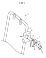
- a latch device 1 for a vehicle is provided, for example, on a frame S (particularly, on a side frame S 1 that constitutes a backrest) of a vehicle seat for an automobile, or the like.
- a bracket S2 made of sheet metal is welded to the side frame S1, and the latch device 1 for a vehicle is fixed using bolts 90 to weld nuts WN fixed to the bracket S2.
- the latch device 1 for a vehicle comprises a housing 2 and mechanical parts such as a latch 30 housed therein.
- a receptacle slot 2A which opens to the right in FIG. 1 is formed in the housing 2, and the latch 30 is brought into a closed state or an open state by a hook-shaped portion entering or exiting this receptacle slot 2A.
- the latch device 1 for a vehicle can establish a locked state, from an unlocked state in which the latch 30 is open, by the latch 30 pressed against and engaged with a rod-shaped portion P1 of a striker P fixed to a vehicle body ( see FIG. 5 ).
- the latch device 1 for a vehicle can establish an unlocked state by pulling a rod 70 so that the latch 30 is operated from the closed state into the open state, as described later in detail.
- the latch device 1 for a vehicle mainly includes a housing 2, a latch 30, a ratchet 40, a lever member 50, a rod 70, and a load-receiving member 80.
- the terms upper (upward)/lower (downward), left/right and front/rear will be used as representing upward/downward, leftward/rightward and frontward/rearward directions indicated by arrows in FIG. 2 for convenience of explanation; it is however to be understood that the latch device 1 for a vehicle may be used in any postures as desired.
- the housing 2 includes a plastic housing 10 made of plastic, and a reinforcing plate 20 made of sheet steel (metal).
- the latch device 1 for a vehicle is designed to achieve significant reduction in weight by adopting the plastic housing 10, and to ensure necessary rigidity and strength by partially providing the reinforcing plate 20.
- the plastic housing 10 includes a lower case 10A and an upper case 10B, each shaped like a tray having one side open; the lower and upper cases 10A, 10B are connected via a hinge 19 formed of a thinned portion, and formed into an integral piece.
- This plastic housing 10 can be formed integrally using a set of dies.
- the upper case 10B can be turned on the hinge 19 relative to the lower case 10A, and the upper case 10B and the lower case 10A can be combined together with their openings fitted to each other, into a box-like shape.
- the lower case 10A includes a base portion 16A shaped like a flat plate, and sidewall portions 17A raised from some of segmented parts of an outer peripheral edge of the base portion 16A, so as to form a tray-like shape.
- a receptacle slot 15A corresponding to the receptacle slot 2A is formed at a lower edge of the base portion 16A.
- Protruding inwardly from the base portion 16A are cylindrical first and second bosses 11, 12 located at the left and right sides of the receptacle slot 15A in positions slightly apart upwardly from the receptacle slot 15A.
- the first boss 11 and the second boss 11 are both formed integrally with the base portion 16A.
- the first boss 11 has a bolt hole 11H pierced along its axial direction in the form of a through hole having a circular cross section.
- the second boss also has a bolt hole 12H pierced along its axial direction in the form of a through hole having a circular cross section.
- the bolt hole 11H and the bolt hole 12H have substantially the same diameter as those of the shanks 91 of bolts 90.
- the upper case 10B is not provided with the first boss 11 or the second boss 12; except for that, its internal structure defining the plastic housing 10 is designed substantially symmetrically to that of the lower case 10A with respect the hinge 19.
- the upper case 10B includes a base portion 16B shaped like a flat plate, and sidewall portions 17B raised from some of segmented parts of an outer peripheral edge of the base portion 16B, so as to form a tray-like shape.
- a receptacle slot 15B corresponding to the receptacle slot 2A is formed at an upper edge (lower edge when viewed after assembly) of the base portion 16B.
- bolt holes 13P, 13Q are formed, which are located at the left and right sides of the receptacle slot 15B in positions slightly apart downwardly (upwardly when viewed after assembly) from the receptacle slot 15A.
- the reinforcing plate 20 is so formed as to cover a region of the outer side of the lower case 10A other than part of its upper area, and includes a base portion 21 shaped like a flat plate, and sidewall portions 27 raised from left-side and right-side parts of an outer peripheral edge of the base portion 21.
- the sidewall portions 27 of the reinforcing plate 20 can be fitted on the sidewall portions 17A of the lower case 10A so as to be tentatively attached to the lower case 10A.
- the base portion 21 has locating holes 22, 23 formed therein in positions corresponding to locating projections protrusively formed on the lower case 10A in positions rearwardly of the first boss 11 and the second boss 12 of the lower case 10A (only projection 11J corresponding to the first boss 11 is shown in FIG. 6 ), which locating holes 22, 23 are designed to fit on these projections.
- a receptacle slot 25 corresponding to the receptacle slot 2A is formed at a lower edge of the base portion 21.
- a flange 28 which is formed at an upper edge of the reinforcing plate 20, by bending outward to bring up an end portion thereof.
- the flange 28 is a portion that is brought into contact with the load-receiving member 80 and withstands a force received from a rod-shaped portion P1 of a striker P ( see FIG. 5 ).
- the latch 30 is a member configured to engage with or disengage from the rod-shaped portion P1 of the striker P, for locking or unlocking the latch device 1 for a vehicle.
- the latch 30 is formed by stamping a thick metal plate, with a first hole 31 pierced through in a direction of its thickness, and is rotatably supported by the plastic housing 10 with the first hole 31 fitted on an outer periphery of the first boss 11.
- the latch 30 is, to be more specific, configured to comprise a latch body 30A made of metal and a cover 30B made of plastic which is softer than the latch body 30A, which cover 30B is disposed to cover a front-side surface and part of a side edge of the latch body 30A.
- the cover 30B is provided to improve smoothness which facilitates sliding on the ratchet 40.
- the cover 30B is mounted onto the latch body 30A in a direction that is along the axial direction of the first hole 31.
- the latch 30 has a slot 32 for receiving the rod-shaped portion P1, and includes a hook-shaped portion 33 which defines an outer side of the slot 32, and a projecting portion 39 which projects at a position near the first hole 31 and defines a side opposed to the hook-shaped portion 33.
- the latch 30 further has a lock recess 34 recessed toward the first hole 31; the lock recess 34 is formed at an upper-and-right-side edge of the latch 30 positioned as shown in FIG. 5 .
- An outer periphery (side) adjacent to the left side of the lock recess 34 is an open contact surface 35 which comes in contact with the ratchet 40 when the latch 30 is brought into an open state, so that the latch 30 is kept in the open state.
- the open contact surface 35 is an outwardly bulging convexly curved surface; in an entire range thereof with which a lock engaging portion 42A of the ratchet 40 (which will be described later) may come in contact, a direction from a surface of the outer periphery to the center of curvature (see arrow in FIG. 5 ) is shifted to one side (to the right, in this embodiment) with respect to the axis of rotation of the latch 30. Accordingly, a force received by the latch 30 from the lock engaging portion 42A acts as a force causing the latch 30 to rotate clockwise, that is, toward the open state.
- the latch 30 includes a pin 36 press-fitted therein which protrudes frontward for the lever member 50 to be pivoted thereon.
- the hook-shaped portion 33 includes: a first support surface 38A configured to be opposed from a lower side, and located nearest, to the rod-shaped portion P1 in the locked state where the rod-shaped portion P1 is engaged therewith as shown in FIG. 5 ; a protruding portion 37 located in a position closer to a distal end of the hook-shaped portion 33 than the first support surface 38A and configured to protrude relative to the first support surface 38A; and a second support surface 38B provided on the protruding portion 37 and configured to be opposed to the rod-shaped portion P1.
- the first support surface 38A and the second support surface 38B are configured to face in different directions, and positioned adjacently so as to allow the rod-shaped portion P1 to concurrently get in contact with the both of them.
- the rod-shaped portion P1 has a shape of a circular cylinder.
- Each of the first support surface 38A and the second support surface 38B is configured to be a flat surface, a convex surface, or a concave surface having a radius of curvature greater than a radius of the rod-shaped portion, in order that the first support surface 38A and the second support surface 38B are made concurrently contactable with the rod-shaped portion P1.
- the first support surface 38A and the second support surface 38B in this embodiment are both flat.
- first support surface 38A and the second support surface 38B are configured to face in different directions and have sufficient lengths, the first support surface 38A and the second support surface 38B are concurrently contactable with the rod-shaped portion P1 when the rod-shaped portion P1 comes in a corner defined by the first support surface 38A and the second support surface 38B.
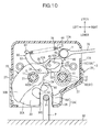
- a side 38C of the protruding portion 37 located at the distal end of the hook-shaped portion 33 is aligned, in an unlocked state as shown in FIG. 10 , with an edge of a receptacle slot 2A when viewed in a direction of an axis X of rotation of the latch 30.
- the distal end portion of the latch 30 and the protruding portion 37 can be designed to have as large a size as possible for enhanced ruggedness without interfering with the entry of the rod-shaped portion P1 into the receptacle slot 2A. In other words, the rod-shaped portion P1 and the latch 30 can be engaged with each other smoothly.
- the protruding portion 37 is exposed out of the aforementioned soft cover 30B. Accordingly, when the second support surface 38B of the protruding portion 37 supports the rod-shaped portion P1, the latch body 30A may be used to support the rod-shaped portion P1 securely. In cases where the cover 30B is not of a coating type but of an attachment type, the cover 30B can be attached onto the latch body 30A with increased ease because the protruding portion 37 is provided in a position exposed outside the cover 30B.
- the protruding portion 37 is, as shown in FIG. 4 , provided along an overall length in an axial direction of the latch body 30A. Therefore, the protruding portion 37 is provided with a sufficient rigidity, that is, enough to securely support the rod-shaped portion P1. Two ends (in the axial direction) of the protruding portion 37 have rounded edges, forming chamfers 38D. Accordingly, the protruding portion 37 would not catch on an inner surface of the plastic housing 10, and thus the latch 30 can be moved smoothly inside the plastic housing 10. It is to be understood that the shape of such a chamfered edge may be provided with a flat surface, or a gently rounded surface is formed as shown in FIG. 4(b) to provide chamfers 38E so that the ridges of the protruding portion 37 in its entirety are shaped like a barrel.
- the ratchet 40 is a substantially plate-shaped member made of metal, of which a second hole 41 perforate in a direction of thickness is fitted on an outer periphery of the second boss 12 of the plastic housing 10 so that the ratchet 40 is rotatably supported on the plastic housing 10.
- the ratchet 40 has an axis of rotation parallel to an axis of rotation of the latch 30.
- the ratchet 40 includes a substantially sectorial main body portion 42 which is located on an upper-left side of the second hole 41, and a lower-left corner of the main body portion 42 is configured to provide a lock engaging portion 42A which is contactable with the latch 30.
- the lock engaging portion 42A enters the lock recess 34 of the latch 30 when the latch 30 is in the closed state, and serves to maintain the closed state of the latch 30, while it comes in contact with the open contact surface 35, and serves to maintain the open state of the latch 30.
- a slender arm 43 From an upper end of the main body portion 42, further upwardly elongated is a slender arm 43, and at a distal end of the arm 43 is formed a hook 44 on which a right end of a tension spring 75 as one example of a biasing member is hitched. Since the end portion of the tension spring 75 is engaged with the hook 44 which is provided by the crooked distal end of the arm 43, the number of parts can be reduced in comparison with another configuration in which a separately provided part such as a rivet placed fixedly into the arm 43 is used to engage the end portion of the tension spring 75.
- the arm 43 also has a hole 48 formed as shown in FIG. 2 , and a rod 70 for operation of the latch device 1 for a vehicle from the locked state to the unlocked state is pivotally connected to the hole 48 by a rivet 71.
- a pin 45 protruding frontward is press-fitted in the main body portion 42 at a location shifted slightly rightward of the lock engaging portion 42A.
- the ratchet 40 includes a flange 47 protruding frontward in the axial direction of the hole at a location around the second hole 41, as shown in FIG. 2 .
- the flange 47 protrudes to an extent corresponding to the thickness of the lever member 50, and when the latch 30 is in the closed state, the lever member 50 is brought into contact with the flange 47 by the biasing force of the tension spring 75, so that play of the lever member 50 is eliminated.
- the lever member 50 is an operation mechanism for interlocking an operation of the ratchet 40 with the latch 30.
- the lever member 50 is an elongate plate-shaped member, and a hole 51 formed substantially at the center along the length is fitted on the pin 36 of the latch 30 so that the lever member 50 is rotatably supported on the latch 30.
- the lever member 50 includes an action arm 52 and an operation arm 53 which extend from the axis of rotation, in the rightward-and-downward direction and in the upward direction, respectively.
- the action arm 52 is provided with a guide hole 52A having a modified quadrilateral shape.
- the pin 45 of the ratchet 40 is disposed inside the guide hole 52A.
- a distal end of the action arm 52 is configured to provide a stopper surface 52B which is in contact with the flange 47 of the ratchet 40 to eliminate play of the lever member 50.
- a distal end of the operation arm 53 is configured as a hook 54, and a left end of the tension spring 75 is hitched on the hook 54.
- the number of parts can be reduced in comparison with another configuration in which a separately provided part such as a rivet placed fixedly into the operation arm 53 is used to engage the end portion of the tension spring 75.
- the tension spring 75 is, as described above, configured such that its two end portions are hitched on the ratchet 40 and the lever member 50, respectively, to impart a biasing force which attracts the main body portion 42 of the ratchet 40 and the operation arm 53 of the lever member 50 toward each other all the time. This biasing force also serves to produce a force biasing the lock engaging portion 42A of the ratchet 40 toward the latch 30.
- the load-receiving member 80 is a plastic member which is configured to come in contact with the rod-shaped portion P1 of the striker P to receive a load from the striker P. Although a detailed description is omitted, the load-receiving member 80 has a load-receiving surface 89A provided on a lower end thereof and configured to come in contact with the rod-shaped portion P1 in the locked state so that a load received from the rod-shaped portion P1 by the load-receiving member 80 is transmitted to the flange 28 (see FIG. 2 ) of the reinforcing plate 20, and received by the reinforcing plate 20.
- each bolt 90 includes a shank 91, a threaded portion 92 provided on a distal end portion of the shank 91, and a flanged head 93 provided at a proximal end thereof.
- the shank 91 is thicker than the threaded portion 92, i.e ., has a diameter larger than a ridge of the threaded portion 92, and a step formed by this difference in diameter serves to receive a fastening force applied when it is tightly fastened to the weld nut WN.
- the lower case 10A and the upper case 10B with the constituent members such as a latch 30 mounted therein are arranged with their open sides facing each other into a boxlike configuration; thereafter, the shank 91 of the bolt 90 is inserted into the bolt hole 11H, and the threaded portion 92 is screwed into the weld nut WN of the bracket S2, so that the resulting assembly is fixed to the bracket S2.
- a spring washer 95 is disposed between the flanged head 93 and the reinforcing plate 20 to hold the latch device 1 for a vehicle between the bracket S2 and the flanged head 93 with the help of the elastic force of the spring washer 95.
- the rod-shaped portion P1 of the striker P is located deepest into the receptacle slot 2A of the housing 2, and the hook-shaped portion 33 of the latch 30 holds the rod-shaped portion P1 inside from below.
- the lock engaging portion 42A is disposed in the lock recess 34 of the latch 30 and restrains the rotation of the latch 30.
- the latch 30 is in the closed state, and the latch device 1 for a vehicle is in the locked state.
- the tension spring 75 is producing a tensile force, and the lock engaging portion 42A of the ratchet 40 is brought into contact with the bottom of the lock recess 34.
- the rod-shaped portion P1 of the striker P is in contact with the load-receiving surface 89A of the load-receiving member 80, and the load applied from the striker P to the latch device 1 for a vehicle is transmitted through the load-receiving member 80 to the flange 28 (see FIG. 2 ) of the reinforcing plate 20 and received by the reinforcing plate 20.
- the latch device 1 for a vehicle operates as follows: first, as shown in FIG. 7 , the ratchet 40 rotates clockwise, and the pin 45 of the ratchet 40 pushes the right upper edge of the guide hole 52A, causing the lever member 50 to rotate counterclockwise while stretching the tension spring 75.
- the force applied to the lever member 50 is gradually causing the latch 30 to rotate clockwise by means of the pin 36.
- the center of curvature of the open contact surface 35 is shifted to the right with respect to the axis of rotation of the latch 30 in the range of contact with the lock engaging portion 42A, and thus the force of the ratchet 40 pushing the latch 30 as produced by the biasing force of the tension spring 75 serves as a force (rotation moment) causing the latch 30 to rotate clockwise, that is, toward the open state.
- the rod-shaped portion P1 of the striker P is caused to enter the receptacle slot 2A, and pressed against the slot 32 of the latch 30, to thereby cause the latch 30 to rotate counterclockwise.
- the lock engaging portion 42A in contact with the open contact surface 35 is caused to slide on the open contact surface 35, and when the rotation of the latch 30 proceeds to a sufficient degree, the lock engaging portion 42A is caused to enter the lock recess 34 with the help of the biasing force of the tension spring 75. Accordingly, the lock state shown in FIG. 5 is restored.
- the rod-shaped portion P1 is in contact with the first support surface 38A at a contact point A and with the second support surface 38B at a contact point B as shown in an enlarged view of FIG. 12 .
- the rod-shaped portion P1 is pressed against the hook-shaped portion 33 in a direction indicated by the arrow in FIG. 12 , and this pressing force is supported by two surfaces because the rod-shaped portion P1 is brought into contact concurrently with the first support surface 38A and with the second support surface 38B. Accordingly, in the latch device 1 for a vehicle as configured according to the present embodiment, even when a force which would tend to cause the latch device 1 for a vehicle to disengage from the striker P is applied, the latch 30 can firmly hold the rod-shaped portion P1.
- the protruding portion 37 is preferably configured such that its protrusion from the first support surface 38A is maximized as long as the rod-shaped portion P1 can smoothly engage into and disengage from the slot 32.
- the second support surface 138B may be configured, as in the latch 130 shown in FIG. 13 , to face toward an axis X of rotation on which the latch 130 is rotatable relative to the housing 2, or to face toward a position closer to the proximal end of the hook-shaped portion 33 than the axis X of rotation; with this configuration, the hook-shaped portion 33 can firmly hold the rod-shaped portion P1 even when a very large force is applied from the rod-shaped portion P1 to the second support surface 138B.
- the second surface 138B may be configured, conversely, to face toward a position closer to the opening of the slot 32 (to the right in FIG. 13 ); with this configuration, the hook-shaped portion 33 and the rod-shaped portion P1 can be engaged with each other with increased ease.
- the cover 30B of the latch 30 is configured to be mounted onto the latch body 30A in a direction that is along the axial direction of the first hole 31; however, an alternative configuration of a latch 250 as shown in FIGS. 14 (a), (b) may be possible in which a cover is mounted onto the latch body 30A from its side (in a direction that is along the plane orthogonal to the thickness direction).
- this cover 230 in this modified embodiment is a part injection molded of a plastic material, and includes a first cover portion 231 that covers at least a part of a surface of one side (a back side in this embodiment) of the latch body 30A extending orthogonal to the axis X of rotation thereof, and a second cover portion 232 that covers at least a part of a surface of the other side (a front side in this embodiment) of the latch body 30A, as well as connecting portions 235A, 235B that connect the first cover portion 231 and the second cover portion 232 to cover the sides of the latch body 30A.
- the cover 230 herein are provided with two or more connecting portions, and thus is configured to be unlikely to come off from the latch body 30A.
- the second cover portion 232 includes a hook cover portion 232A that covers a distal end portion of the hook-shaped portion 33, and a projection cover portion 232B that covers a lower half of the projecting portion 39.
- the connecting portion 235A extends to cover a portion of the side of the latch body 30A along the inner surface of the slot 32 and the distal end of the projecting portion 39.
- the connecting portion 235B extends to cover a portion of the latch body 30A over a lower side of the hook-shaped portion 33.
- the first cover portion 231 and the second cover portion 232 are configured such that they do not overlap each other as viewed in a direction along the axis X of rotation of the latch body 30A.
- the cover 230 can be made by injection molding in which a mold is separated in a direction along the axis X of rotation, and thus the removal of the mold is performed easily.
- the first cover portion 231 has a through hole 237 formed in a position corresponding to the first hole 31 in which the first boss 11 as a pivot shaft of the latch body 30A is disposed.
- the first cover portion 231 also has a through hole 238 formed in a position corresponding to the pin 36 of the latch body 30A. Further, at an edge of the first cover portion 231 opposed to the slot 32 ( i.e ., the left edge), an engaging portion 239 extending around the side of the latch body 30A to engage with the latch body 30A is provided.
- the cover 230 configured as described above is designed to be mounted onto the latch body 30A in a direction along the plane orthogonal to the axis X of rotation. To be more specific, the cover 230 is mounted onto the latch body 30A in a lengthwise direction of the slot 32.
- the hook-shaped portion 33 is fitted into the loop 241 while the first cover portion 231 is being slightly warped rearward, and the projecting portion 39 is sandwiched between the first cover portion 231 and the projection cover portion 232B.
- the through hole 238 is fitted on the pin 36, and the engaging portion 239 is caused to overpass the rear side surface of the latch body 30A and engaged on the left side of the latch body 30A.
- the cover 230 becomes unlikely to come off from the latch body 30.
- the engagements between the hook-shaped portion 33 and the loop 241 fitted thereon and between the projecting portion 39 and the projection cover 232B engaged thereon serve to prevent the cover 230 from slipping in a direction along the axis X of rotation relative to the latch body 30A.
- the latch 250 assembled as described above is pivoted on the first boss 11 inserted in the first hole 31 and the through hole 237.
- the cover 230 is also restrained from slip in a direction orthogonal to the axis X of rotation, and thus is prevented from slipping or coming off from the latch body 30A.
- the projecting portion 37 is exposed through the cover 37, and thus the operating noise of the latch 30 can be reduced with the help of the soft cover 37, while the projecting portion 37 exposed through the cover 230 can be used to support the rod-shaped portion P1 so that the latch body 30A itself firmly support the rod-shaped portion P1. Moreover, when the cover 230 is mounted on the latch body 30A, the mounting work is easy.
- latch device 1 for a vehicle
- one example not illustrated herein may be configured to provide a cover 30B for the latch 30 by coating rubber on the latch body 30A.
- the latch device 1 for a vehicle may be provided, not only on a backrest of a seat for a vehicle such as a car, but on a seating portion or legs of a seat for a vehicle, or may be used as a device for locking a portion for closing an opening of a trunk of a car or the like.
- the seat for a vehicle may include seats for a vehicle other than a car, such as a ship, an aircraft, etc.
Landscapes
- Engineering & Computer Science (AREA)
- Aviation & Aerospace Engineering (AREA)
- Transportation (AREA)
- Mechanical Engineering (AREA)
- Lock And Its Accessories (AREA)
- Seats For Vehicles (AREA)
Abstract
Description
- The present invention relates to latch devices for a vehicle, and particularly to a latch device for a vehicle for use in locking a vehicle part.
- In general, a seat provided rotatably relative to a vehicle body has its leg or the like provided with a latch device; this latch device is engaged with a rod-shaped portion of a striker fixed to the vehicle body, and the seat is thereby locked to the vehicle body. Such a latch device is configured, for example as disclosed in
Patent Literature 1, such that a latch, a ratchet or any other rotatable part is supported by a base plate. The latch has a slot formed therein, and the slot is configured to receive the striker so that the latch is engaged with the striker. - Patent Literature 1:
JP 4318213 B2 - However, as an insurance against a possibility that such a strong force as would separate the whole latch device from a striker could be exerted on the latch device, there is a need for an enhanced capability of a latch to hold the striker.
- With this in view, it is an object of the present invention to provide a latch device for a vehicle, in which an enhanced capability to hold a rod-shaped portion of a striker or the like is provided.
- It is another object of the present invention to provide a latch constructed less fragilely, and more smoothly engageable with a rod-shaped portion.
- It is still another object to reduce the possibility that a latch will catch on a housing, so that the latch can be operated smoothly.
- The present invention which may solve the above-described problems can be embodied in a latch device for a vehicle, for locking or unlocking by engaging with or disengaging from a rod-shaped portion, which latch device for a vehicle comprises: a housing; and a latch rotatably supported by the housing, the latch including a hook-shaped portion engageable with the rod-shaped portion to form a locked state, wherein the hook-shaped portion includes: a first support surface configured to be opposed to the rod-shaped portion in the locked state; a protruding portion located in a position closer to a distal end of the hook-shaped portion than the first support surface, the protruding portion being configured to protrude relative to the first support surface; and a second support surface provided on the protruding portion, the second support surface being configured to be opposed to the rod-shaped portion, and wherein the first support surface and the second support surface are configured to face in different directions, and to thereby be concurrently contactable with the rod-shaped portion.
- With the latch device for a vehicle configured as described above, when a strong force as would separate the whole latch device for a vehicle from a striker is given to the latch device for a vehicle, the rod-shaped portion would slip off the first support surface of the hook-shaped portion, but come in contact with the second support surface on the protruding portion which protrudes relative to the first support portion. Then, the rod-shaped portion is simultaneously in contact with and supported by the both of the first support surface and the second support surface, and thus the hook-shaped portion can hold the rod-shaped portion firmly.
- The latch device for a vehicle as described above may be configured such that the rod-shaped portion has a shape of a circular cylinder, wherein the first support surface is a flat surface, a convex surface, or a concave surface having a radius of curvature greater than a radius of the rod-shaped portion, and wherein the second support surface is a flat surface, a convex surface, or a concave surface having a radius of curvature greater than the radius of the rod-shaped portion.
- With this configuration, in which the rod-shaped portion has a shape of a circular cylinder, the first support surface and the second support surface can be configured to be simultaneously contactable with the rod-shaped portion.
- In the latch device for a vehicle as described above, the second support surface may preferably be configured to face toward an axis of rotation on which the latch is rotatable relative to the housing, or to face toward a position closer to a proximal end of the hook-shaped portion than the axis of rotation.
- With this configuration, the second support surface can be made more likely to support the rod-shaped portion, so that the hook-shaped portion can hold the rod-shaped portion more firmly.
- The latch device for a vehicle as described above may preferably be configured such that the housing has a receptacle slot so formed as to receive the rod-shaped portion therein, wherein a side of the protruding portion located at the distal end of the hook-shaped portion of the latch in an unlocked state is aligned with an edge of the receptacle slot when viewed in a direction of an axis of rotation of the latch.
- With this configuration, the distal-end portion and the protrusion of the latch can be designed to be as large as possible without hampering the rod-shaped portion from entering the receptacle slot.
- In the latch device for a vehicle as described above, the latch may preferably comprise a latch body, and a cover that covers part of the latch body, the cover being softer than the latch body, wherein the protruding portion is exposed out of the cover.
- With this configuration, the soft cover can serve to reduce operating noise of the latch, and the rod-shaped portion can be supported firmly by the latch body per se because the protruding portion is exposed out of the cover.
- In the latch device for a vehicle as described above, the protruding portion may preferably be provided along an overall length in an axial direction of the latch.
- With this configuration in which the protruding portion is provided along the overall length in the axial direction of the latch, the rigidity of the protruding portion is enhanced and the rod-shaped portion can be supported firmly thereby.
- In the latch device for a vehicle as described above, the protruding portion may preferably have two ends in an axial direction of the latch, the two ends having chamfered edges.
- With this configuration in which the two ends of the protruding portion have chamfered edges, i.e., edges chamfered with flat surfaces or edges rounded, the possibility that the latch will catch on the housing can be reduced so that the latch can be operated smoothly.
- The other features and advantages of the present invention will be more apparent from the following description elaborated with reference to the accompanying drawings.
-
-
FIG. 1 is a perspective view of a seat frame of a vehicle seat in which a latch device for a vehicle is provided. -
FIG. 2 is an exploded perspective view of the latch device for a vehicle. -
FIG. 3 is an enlarged view of a latch. -
FIG. 4 shows schematics as viewed in a direction indicated by the arrow A ofFIG. 3 . -
FIG. 5 is a sectional view showing the latch device for a vehicle in a locked state. -
FIG. 6 is a sectional view for explaining a structure for rotatably supporting the latch. -
FIG. 7 is a diagram for explaining an operation of the latch device for a vehicle, showing a state in which a rod has been pulled slightly. -
FIG. 8 is a diagram for explaining an operation of the latch device for a vehicle, showing a state in which the rod has been pulled greatly. -
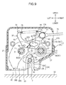
FIG. 9 is a diagram for explaining an operation of the latch device for a vehicle, showing a state in which the rod has been returned with a ratchet resting in contact with the latch. -
FIG. 10 is a diagram for explaining an operation of the latch device for a vehicle, showing an unlocked state. -
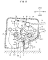
FIG. 11 is a diagram showing a state resulting from an attempt made to pull away the latch device for a vehicle from a striker in an upward direction. -
FIG. 12 is an enlarged view showing a state of contact between the hook-shaped portion and the rod-shaped portion inFIG. 11 -
FIG. 13 is an enlarged view of the latch according to a modified embodiment. -
FIG. 14 shows the latch according to another modified embodiment, and includes (a) a perspective view of a cover, and (b) a view for explaining a process of mounting the cover on a latch body. - Hereafter, a detailed description will be given of one embodiment of a latch device for a vehicle according to the present invention with reference made to the accompanying drawings. As shown in
FIG. 1 , alatch device 1 for a vehicle according to one embodiment is provided, for example, on a frame S (particularly, on aside frame S 1 that constitutes a backrest) of a vehicle seat for an automobile, or the like. As one example, a bracket S2 made of sheet metal is welded to the side frame S1, and thelatch device 1 for a vehicle is fixed usingbolts 90 to weld nuts WN fixed to the bracket S2. - The
latch device 1 for a vehicle comprises ahousing 2 and mechanical parts such as alatch 30 housed therein. Areceptacle slot 2A which opens to the right inFIG. 1 is formed in thehousing 2, and thelatch 30 is brought into a closed state or an open state by a hook-shaped portion entering or exiting thisreceptacle slot 2A. Thelatch device 1 for a vehicle can establish a locked state, from an unlocked state in which thelatch 30 is open, by thelatch 30 pressed against and engaged with a rod-shaped portion P1 of a striker P fixed to a vehicle body (seeFIG. 5 ). Thelatch device 1 for a vehicle can establish an unlocked state by pulling arod 70 so that thelatch 30 is operated from the closed state into the open state, as described later in detail. - As shown in
FIG. 2 , thelatch device 1 for a vehicle mainly includes ahousing 2, alatch 30, aratchet 40, alever member 50, arod 70, and a load-receivingmember 80. In the following description of the structure of thelatch device 1 for a vehicle, the terms upper (upward)/lower (downward), left/right and front/rear will be used as representing upward/downward, leftward/rightward and frontward/rearward directions indicated by arrows inFIG. 2 for convenience of explanation; it is however to be understood that thelatch device 1 for a vehicle may be used in any postures as desired. - The
housing 2 includes aplastic housing 10 made of plastic, and a reinforcingplate 20 made of sheet steel (metal). Thelatch device 1 for a vehicle is designed to achieve significant reduction in weight by adopting theplastic housing 10, and to ensure necessary rigidity and strength by partially providing the reinforcingplate 20. - The
plastic housing 10 includes alower case 10A and anupper case 10B, each shaped like a tray having one side open; the lower andupper cases hinge 19 formed of a thinned portion, and formed into an integral piece. Thisplastic housing 10 can be formed integrally using a set of dies. Theupper case 10B can be turned on thehinge 19 relative to thelower case 10A, and theupper case 10B and thelower case 10A can be combined together with their openings fitted to each other, into a box-like shape. - The
lower case 10A includes abase portion 16A shaped like a flat plate, andsidewall portions 17A raised from some of segmented parts of an outer peripheral edge of thebase portion 16A, so as to form a tray-like shape. Areceptacle slot 15A corresponding to thereceptacle slot 2A is formed at a lower edge of thebase portion 16A. Protruding inwardly from thebase portion 16A are cylindrical first andsecond bosses receptacle slot 15A in positions slightly apart upwardly from thereceptacle slot 15A. Thefirst boss 11 and thesecond boss 11 are both formed integrally with thebase portion 16A. - The
first boss 11 has abolt hole 11H pierced along its axial direction in the form of a through hole having a circular cross section. The second boss also has abolt hole 12H pierced along its axial direction in the form of a through hole having a circular cross section. Thebolt hole 11H and thebolt hole 12H have substantially the same diameter as those of theshanks 91 ofbolts 90. - The
upper case 10B is not provided with thefirst boss 11 or thesecond boss 12; except for that, its internal structure defining theplastic housing 10 is designed substantially symmetrically to that of thelower case 10A with respect thehinge 19. Theupper case 10B includes abase portion 16B shaped like a flat plate, andsidewall portions 17B raised from some of segmented parts of an outer peripheral edge of thebase portion 16B, so as to form a tray-like shape. Areceptacle slot 15B corresponding to thereceptacle slot 2A is formed at an upper edge (lower edge when viewed after assembly) of thebase portion 16B. In thebase portion 16B, bolt holes 13P, 13Q are formed, which are located at the left and right sides of thereceptacle slot 15B in positions slightly apart downwardly (upwardly when viewed after assembly) from thereceptacle slot 15A. - The reinforcing
plate 20 is so formed as to cover a region of the outer side of thelower case 10A other than part of its upper area, and includes abase portion 21 shaped like a flat plate, andsidewall portions 27 raised from left-side and right-side parts of an outer peripheral edge of thebase portion 21. Although not illustrated in detail, thesidewall portions 27 of the reinforcingplate 20 can be fitted on thesidewall portions 17A of thelower case 10A so as to be tentatively attached to thelower case 10A. - The
base portion 21 has locatingholes lower case 10A in positions rearwardly of thefirst boss 11 and thesecond boss 12 of thelower case 10A (onlyprojection 11J corresponding to thefirst boss 11 is shown inFIG. 6 ), which locating holes 22, 23 are designed to fit on these projections. Areceptacle slot 25 corresponding to thereceptacle slot 2A is formed at a lower edge of thebase portion 21. - On an outer side of the reinforcing
plate 20 is provided aflange 28 which is formed at an upper edge of the reinforcingplate 20, by bending outward to bring up an end portion thereof. Theflange 28 is a portion that is brought into contact with the load-receivingmember 80 and withstands a force received from a rod-shaped portion P1 of a striker P (seeFIG. 5 ). - The
latch 30 is a member configured to engage with or disengage from the rod-shaped portion P1 of the striker P, for locking or unlocking thelatch device 1 for a vehicle. Thelatch 30 is formed by stamping a thick metal plate, with afirst hole 31 pierced through in a direction of its thickness, and is rotatably supported by theplastic housing 10 with thefirst hole 31 fitted on an outer periphery of thefirst boss 11. Thelatch 30 is, to be more specific, configured to comprise alatch body 30A made of metal and acover 30B made of plastic which is softer than thelatch body 30A, which cover 30B is disposed to cover a front-side surface and part of a side edge of thelatch body 30A. Thecover 30B is provided to improve smoothness which facilitates sliding on theratchet 40. Thecover 30B is mounted onto thelatch body 30A in a direction that is along the axial direction of thefirst hole 31. - As shown in
FIG. 3 , thelatch 30 has aslot 32 for receiving the rod-shaped portion P1, and includes a hook-shapedportion 33 which defines an outer side of theslot 32, and a projectingportion 39 which projects at a position near thefirst hole 31 and defines a side opposed to the hook-shapedportion 33. Thelatch 30 further has alock recess 34 recessed toward thefirst hole 31; thelock recess 34 is formed at an upper-and-right-side edge of thelatch 30 positioned as shown inFIG. 5 . An outer periphery (side) adjacent to the left side of thelock recess 34 is anopen contact surface 35 which comes in contact with theratchet 40 when thelatch 30 is brought into an open state, so that thelatch 30 is kept in the open state. Theopen contact surface 35 is an outwardly bulging convexly curved surface; in an entire range thereof with which alock engaging portion 42A of the ratchet 40 (which will be described later) may come in contact, a direction from a surface of the outer periphery to the center of curvature (see arrow inFIG. 5 ) is shifted to one side (to the right, in this embodiment) with respect to the axis of rotation of thelatch 30. Accordingly, a force received by thelatch 30 from thelock engaging portion 42A acts as a force causing thelatch 30 to rotate clockwise, that is, toward the open state. - The
latch 30 includes apin 36 press-fitted therein which protrudes frontward for thelever member 50 to be pivoted thereon. - The hook-shaped
portion 33 includes: afirst support surface 38A configured to be opposed from a lower side, and located nearest, to the rod-shaped portion P1 in the locked state where the rod-shaped portion P1 is engaged therewith as shown inFIG. 5 ; a protrudingportion 37 located in a position closer to a distal end of the hook-shapedportion 33 than thefirst support surface 38A and configured to protrude relative to thefirst support surface 38A; and asecond support surface 38B provided on the protrudingportion 37 and configured to be opposed to the rod-shaped portion P1. Thefirst support surface 38A and thesecond support surface 38B are configured to face in different directions, and positioned adjacently so as to allow the rod-shaped portion P1 to concurrently get in contact with the both of them. In the present embodiment, the rod-shaped portion P1 has a shape of a circular cylinder. Each of thefirst support surface 38A and thesecond support surface 38B is configured to be a flat surface, a convex surface, or a concave surface having a radius of curvature greater than a radius of the rod-shaped portion, in order that thefirst support surface 38A and thesecond support surface 38B are made concurrently contactable with the rod-shaped portion P1. By way of example, thefirst support surface 38A and thesecond support surface 38B in this embodiment are both flat. Since thefirst support surface 38A and thesecond support surface 38B are configured to face in different directions and have sufficient lengths, thefirst support surface 38A and thesecond support surface 38B are concurrently contactable with the rod-shaped portion P1 when the rod-shaped portion P1 comes in a corner defined by thefirst support surface 38A and thesecond support surface 38B. - A
side 38C of the protrudingportion 37 located at the distal end of the hook-shapedportion 33 is aligned, in an unlocked state as shown inFIG. 10 , with an edge of areceptacle slot 2A when viewed in a direction of an axis X of rotation of thelatch 30. With this configuration, the distal end portion of thelatch 30 and the protrudingportion 37 can be designed to have as large a size as possible for enhanced ruggedness without interfering with the entry of the rod-shaped portion P1 into thereceptacle slot 2A. In other words, the rod-shaped portion P1 and thelatch 30 can be engaged with each other smoothly. - The protruding
portion 37 is exposed out of the aforementionedsoft cover 30B. Accordingly, when thesecond support surface 38B of the protrudingportion 37 supports the rod-shaped portion P1, thelatch body 30A may be used to support the rod-shaped portion P1 securely. In cases where thecover 30B is not of a coating type but of an attachment type, thecover 30B can be attached onto thelatch body 30A with increased ease because the protrudingportion 37 is provided in a position exposed outside thecover 30B. - The protruding
portion 37 is, as shown inFIG. 4 , provided along an overall length in an axial direction of thelatch body 30A. Therefore, the protrudingportion 37 is provided with a sufficient rigidity, that is, enough to securely support the rod-shaped portion P1. Two ends (in the axial direction) of the protrudingportion 37 have rounded edges, formingchamfers 38D. Accordingly, the protrudingportion 37 would not catch on an inner surface of theplastic housing 10, and thus thelatch 30 can be moved smoothly inside theplastic housing 10. It is to be understood that the shape of such a chamfered edge may be provided with a flat surface, or a gently rounded surface is formed as shown inFIG. 4(b) to providechamfers 38E so that the ridges of the protrudingportion 37 in its entirety are shaped like a barrel. - As shown in
FIGS. 2 and5 , theratchet 40 is a substantially plate-shaped member made of metal, of which asecond hole 41 perforate in a direction of thickness is fitted on an outer periphery of thesecond boss 12 of theplastic housing 10 so that theratchet 40 is rotatably supported on theplastic housing 10. Theratchet 40 has an axis of rotation parallel to an axis of rotation of thelatch 30. Theratchet 40 includes a substantially sectorialmain body portion 42 which is located on an upper-left side of thesecond hole 41, and a lower-left corner of themain body portion 42 is configured to provide alock engaging portion 42A which is contactable with thelatch 30. Thelock engaging portion 42A enters thelock recess 34 of thelatch 30 when thelatch 30 is in the closed state, and serves to maintain the closed state of thelatch 30, while it comes in contact with theopen contact surface 35, and serves to maintain the open state of thelatch 30. - From an upper end of the
main body portion 42, further upwardly elongated is aslender arm 43, and at a distal end of thearm 43 is formed ahook 44 on which a right end of atension spring 75 as one example of a biasing member is hitched. Since the end portion of thetension spring 75 is engaged with thehook 44 which is provided by the crooked distal end of thearm 43, the number of parts can be reduced in comparison with another configuration in which a separately provided part such as a rivet placed fixedly into thearm 43 is used to engage the end portion of thetension spring 75. Thearm 43 also has ahole 48 formed as shown inFIG. 2 , and arod 70 for operation of thelatch device 1 for a vehicle from the locked state to the unlocked state is pivotally connected to thehole 48 by arivet 71. - As shown in
FIG. 5 , apin 45 protruding frontward is press-fitted in themain body portion 42 at a location shifted slightly rightward of thelock engaging portion 42A. Moreover, theratchet 40 includes aflange 47 protruding frontward in the axial direction of the hole at a location around thesecond hole 41, as shown inFIG. 2 . Theflange 47 protrudes to an extent corresponding to the thickness of thelever member 50, and when thelatch 30 is in the closed state, thelever member 50 is brought into contact with theflange 47 by the biasing force of thetension spring 75, so that play of thelever member 50 is eliminated. - The
lever member 50 is an operation mechanism for interlocking an operation of theratchet 40 with thelatch 30. Thelever member 50 is an elongate plate-shaped member, and ahole 51 formed substantially at the center along the length is fitted on thepin 36 of thelatch 30 so that thelever member 50 is rotatably supported on thelatch 30. - The
lever member 50 includes anaction arm 52 and anoperation arm 53 which extend from the axis of rotation, in the rightward-and-downward direction and in the upward direction, respectively. Theaction arm 52 is provided with aguide hole 52A having a modified quadrilateral shape. Thepin 45 of theratchet 40 is disposed inside theguide hole 52A. A distal end of theaction arm 52 is configured to provide astopper surface 52B which is in contact with theflange 47 of theratchet 40 to eliminate play of thelever member 50. A distal end of theoperation arm 53 is configured as ahook 54, and a left end of thetension spring 75 is hitched on thehook 54. Since the end portion of thetension spring 75 is engaged with thehook 54 which is provided by the crooked distal end of theoperation arm 53, the number of parts can be reduced in comparison with another configuration in which a separately provided part such as a rivet placed fixedly into theoperation arm 53 is used to engage the end portion of thetension spring 75. - The
tension spring 75 is, as described above, configured such that its two end portions are hitched on theratchet 40 and thelever member 50, respectively, to impart a biasing force which attracts themain body portion 42 of theratchet 40 and theoperation arm 53 of thelever member 50 toward each other all the time. This biasing force also serves to produce a force biasing thelock engaging portion 42A of theratchet 40 toward thelatch 30. - The load-receiving
member 80 is a plastic member which is configured to come in contact with the rod-shaped portion P1 of the striker P to receive a load from the striker P. Although a detailed description is omitted, the load-receivingmember 80 has a load-receivingsurface 89A provided on a lower end thereof and configured to come in contact with the rod-shaped portion P1 in the locked state so that a load received from the rod-shaped portion P1 by the load-receivingmember 80 is transmitted to the flange 28 (seeFIG. 2 ) of the reinforcingplate 20, and received by the reinforcingplate 20. - As shown in
FIG. 6 , thelower case 10A and theupper case 10B are joined together to make a box-shaped configuration, and are combined with the reinforcingplate 20 and fixed to the bracket S2 by thebolts 90. Eachbolt 90 includes ashank 91, a threadedportion 92 provided on a distal end portion of theshank 91, and aflanged head 93 provided at a proximal end thereof. Theshank 91 is thicker than the threadedportion 92, i.e., has a diameter larger than a ridge of the threadedportion 92, and a step formed by this difference in diameter serves to receive a fastening force applied when it is tightly fastened to the weld nut WN. With this configuration, the costs can be reduced in comparison with another configuration in which a metal collar is used. - The
lower case 10A and theupper case 10B with the constituent members such as alatch 30 mounted therein are arranged with their open sides facing each other into a boxlike configuration; thereafter, theshank 91 of thebolt 90 is inserted into thebolt hole 11H, and the threadedportion 92 is screwed into the weld nut WN of the bracket S2, so that the resulting assembly is fixed to the bracket S2. Aspring washer 95 is disposed between theflanged head 93 and the reinforcingplate 20 to hold thelatch device 1 for a vehicle between the bracket S2 and theflanged head 93 with the help of the elastic force of thespring washer 95. The fastening state at thefirst boss 11 with thebolt 90 has been described above with reference toFIG. 6 ; it is however to be understood that fastening at thesecond boss 12 with thebolt 90 may be carried out in exactly the same manner. Thus, a description of the fastening at thesecond boss 12 will not be given herein. - A description will be given of an operation of the
latch device 1 for a vehicle, configured as described above. - In the pre-operated state shown in
FIG. 5 , the rod-shaped portion P1 of the striker P is located deepest into thereceptacle slot 2A of thehousing 2, and the hook-shapedportion 33 of thelatch 30 holds the rod-shaped portion P1 inside from below. Thelock engaging portion 42A is disposed in thelock recess 34 of thelatch 30 and restrains the rotation of thelatch 30. In other words, thelatch 30 is in the closed state, and thelatch device 1 for a vehicle is in the locked state. In this state, thetension spring 75 is producing a tensile force, and thelock engaging portion 42A of theratchet 40 is brought into contact with the bottom of thelock recess 34. The rod-shaped portion P1 of the striker P is in contact with the load-receivingsurface 89A of the load-receivingmember 80, and the load applied from the striker P to thelatch device 1 for a vehicle is transmitted through the load-receivingmember 80 to the flange 28 (seeFIG. 2 ) of the reinforcingplate 20 and received by the reinforcingplate 20. - Starting from the pre-operated state shown in
FIG. 5 , when therod 70 is pulled, thelatch device 1 for a vehicle operates as follows: first, as shown inFIG. 7 , theratchet 40 rotates clockwise, and thepin 45 of theratchet 40 pushes the right upper edge of theguide hole 52A, causing thelever member 50 to rotate counterclockwise while stretching thetension spring 75. InFIG. 7 , though no substantial change would be seen from the state shown inFIG. 5 , the force applied to thelever member 50 is gradually causing thelatch 30 to rotate clockwise by means of thepin 36. - When the
rod 70 is pulled further, as shown inFIG. 8 , theratchet 40 is caused to further rotate clockwise, and thelock engaging portion 42A is fully disengaged from thelock recess 34. Then, thelatch 30 is caused to rotate clockwise by the force received through thepin 36 from thelever member 50, and thelock engaging portion 42A is disposed to face theopen contact surface 35 of thelatch 30. - From the state shown in
FIG. 8 , when therod 70 is allowed to return by the action of the tensile force of thetension spring 75, as shown inFIG. 9 , thelock engaging portion 42A of theratchet 40 is brought into contact with theopen contact surface 35 of thelatch 30. Then, the force of theratchet 40 pushing thelatch 30 is directed from the point of contact between thelock engaging portion 42A and theopen contact surface 35 toward the center of curvature of theopen contact surface 35. Hereupon, the center of curvature of theopen contact surface 35 is shifted to the right with respect to the axis of rotation of thelatch 30 in the range of contact with thelock engaging portion 42A, and thus the force of theratchet 40 pushing thelatch 30 as produced by the biasing force of thetension spring 75 serves as a force (rotation moment) causing thelatch 30 to rotate clockwise, that is, toward the open state. - In this way, when this rotation moment causes the
latch 30 to rotate clockwise with theopen contact surface 35 caused to slide on thelock engaging portion 42A, as shown inFIG. 10 , thelatch 30 gets in the open state, so that the rod-shaped portion P1 of the striker P can be disengaged from thereceptacle slot 2A. In other words, thelatch device 1 for a vehicle is shifted to the unlocked state. - To return the
latch device 1 for a vehicle from the unlocked state to the locked state, starting from the state as shown inFIG. 10 , the rod-shaped portion P1 of the striker P is caused to enter thereceptacle slot 2A, and pressed against theslot 32 of thelatch 30, to thereby cause thelatch 30 to rotate counterclockwise. Then, thelock engaging portion 42A in contact with theopen contact surface 35 is caused to slide on theopen contact surface 35, and when the rotation of thelatch 30 proceeds to a sufficient degree, thelock engaging portion 42A is caused to enter thelock recess 34 with the help of the biasing force of thetension spring 75. Accordingly, the lock state shown inFIG. 5 is restored. - Incidentally, if an abrupt operation of tilting forward the side frame S1 (see
FIG. 1 ) of the backrest of the vehicle seat with thelatch device 1 for a vehicle in the locked state as shown inFIG. 5 is performed without manipulating therod 70, thelatch device 1 for a vehicle is moved upward away from the striker P. Then, the rod-shaped portion P1 is caused to strongly push thefirst support surface 38A of the hook-shapedportion 33 of thelatch 30, and causes thelatch 30 to rotate clockwise as shown inFIG. 11 . The rod-shaped portion P1 thus slides on the first supports surface toward the distal-end side of the hook-shaped portion 33 (toward the exit-side of the slot 32), and comes in contact with the protrudingportion 37. - At this time, the rod-shaped portion P1 is in contact with the
first support surface 38A at a contact point A and with thesecond support surface 38B at a contact point B as shown in an enlarged view ofFIG. 12 . To be more specific, the rod-shaped portion P1 is pressed against the hook-shapedportion 33 in a direction indicated by the arrow inFIG. 12 , and this pressing force is supported by two surfaces because the rod-shaped portion P1 is brought into contact concurrently with thefirst support surface 38A and with thesecond support surface 38B. Accordingly, in thelatch device 1 for a vehicle as configured according to the present embodiment, even when a force which would tend to cause thelatch device 1 for a vehicle to disengage from the striker P is applied, thelatch 30 can firmly hold the rod-shaped portion P1. - Although one embodiment of the present invention has been described above, the present invention is not limited to the above-described embodiment, and can be put into practice with modifications made where appropriate.
- For example, the protruding
portion 37 is preferably configured such that its protrusion from thefirst support surface 38A is maximized as long as the rod-shaped portion P1 can smoothly engage into and disengage from theslot 32. Meanwhile, thesecond support surface 138B may be configured, as in thelatch 130 shown inFIG. 13 , to face toward an axis X of rotation on which thelatch 130 is rotatable relative to thehousing 2, or to face toward a position closer to the proximal end of the hook-shapedportion 33 than the axis X of rotation; with this configuration, the hook-shapedportion 33 can firmly hold the rod-shaped portion P1 even when a very large force is applied from the rod-shaped portion P1 to thesecond support surface 138B. On the other hand, thesecond surface 138B may be configured, conversely, to face toward a position closer to the opening of the slot 32 (to the right inFIG. 13 ); with this configuration, the hook-shapedportion 33 and the rod-shaped portion P1 can be engaged with each other with increased ease. - In the above-described embodiment, the
cover 30B of thelatch 30 is configured to be mounted onto thelatch body 30A in a direction that is along the axial direction of thefirst hole 31; however, an alternative configuration of alatch 250 as shown inFIGS. 14 (a), (b) may be possible in which a cover is mounted onto thelatch body 30A from its side (in a direction that is along the plane orthogonal to the thickness direction). More specifically, thiscover 230 in this modified embodiment is a part injection molded of a plastic material, and includes afirst cover portion 231 that covers at least a part of a surface of one side (a back side in this embodiment) of thelatch body 30A extending orthogonal to the axis X of rotation thereof, and asecond cover portion 232 that covers at least a part of a surface of the other side (a front side in this embodiment) of thelatch body 30A, as well as connectingportions first cover portion 231 and thesecond cover portion 232 to cover the sides of thelatch body 30A. Thecover 230 herein are provided with two or more connecting portions, and thus is configured to be unlikely to come off from thelatch body 30A. - The
second cover portion 232 includes ahook cover portion 232A that covers a distal end portion of the hook-shapedportion 33, and aprojection cover portion 232B that covers a lower half of the projectingportion 39. - The connecting
portion 235A extends to cover a portion of the side of thelatch body 30A along the inner surface of theslot 32 and the distal end of the projectingportion 39. On the other hand, the connectingportion 235B extends to cover a portion of thelatch body 30A over a lower side of the hook-shapedportion 33. With this configuration, thefirst cover portion 231, the connectingportion 235A, thehook cover portion 232A, and the connectingportion 235B form aclosed loop 241 as viewed from a lateral direction (seeFIG. 14 (a) ). - As shown in
FIG. 14 (b) , thefirst cover portion 231 and thesecond cover portion 232 are configured such that they do not overlap each other as viewed in a direction along the axis X of rotation of thelatch body 30A. With this configuration, thecover 230 can be made by injection molding in which a mold is separated in a direction along the axis X of rotation, and thus the removal of the mold is performed easily. - The
first cover portion 231 has a throughhole 237 formed in a position corresponding to thefirst hole 31 in which thefirst boss 11 as a pivot shaft of thelatch body 30A is disposed. Thefirst cover portion 231 also has a throughhole 238 formed in a position corresponding to thepin 36 of thelatch body 30A. Further, at an edge of thefirst cover portion 231 opposed to the slot 32 (i.e., the left edge), an engagingportion 239 extending around the side of thelatch body 30A to engage with thelatch body 30A is provided. - The
cover 230 configured as described above is designed to be mounted onto thelatch body 30A in a direction along the plane orthogonal to the axis X of rotation. To be more specific, thecover 230 is mounted onto thelatch body 30A in a lengthwise direction of theslot 32. In this mounting process, the hook-shapedportion 33 is fitted into theloop 241 while thefirst cover portion 231 is being slightly warped rearward, and the projectingportion 39 is sandwiched between thefirst cover portion 231 and theprojection cover portion 232B. In this process, the throughhole 238 is fitted on thepin 36, and the engagingportion 239 is caused to overpass the rear side surface of thelatch body 30A and engaged on the left side of thelatch body 30A. By these engagements between the hook-shapedportion 33 and theloop 241 fitted thereon, between the projectingportion 39 and theprojection cover portion 232B engaged thereon, between the engagingportion 239 and the side of thelatch body 30A engaged thereby and between thepin 36 and the throughhole 238 fitted thereon, thecover 230 becomes unlikely to come off from thelatch body 30. In particular, the engagements between the hook-shapedportion 33 and theloop 241 fitted thereon and between the projectingportion 39 and theprojection cover 232B engaged thereon serve to prevent thecover 230 from slipping in a direction along the axis X of rotation relative to thelatch body 30A. - The
latch 250 assembled as described above is pivoted on thefirst boss 11 inserted in thefirst hole 31 and the throughhole 237. With this configuration in which the latch is pivotally supported on thefirst boss 11, thecover 230 is also restrained from slip in a direction orthogonal to the axis X of rotation, and thus is prevented from slipping or coming off from thelatch body 30A. - In this modified example of the
cover 230 as well, the projectingportion 37 is exposed through thecover 37, and thus the operating noise of thelatch 30 can be reduced with the help of thesoft cover 37, while the projectingportion 37 exposed through thecover 230 can be used to support the rod-shaped portion P1 so that thelatch body 30A itself firmly support the rod-shaped portion P1. Moreover, when thecover 230 is mounted on thelatch body 30A, the mounting work is easy. - To further elaborate other variations of the
latch device 1 for a vehicle, one example not illustrated herein may be configured to provide acover 30B for thelatch 30 by coating rubber on thelatch body 30A. - Furthermore, the
latch device 1 for a vehicle may be provided, not only on a backrest of a seat for a vehicle such as a car, but on a seating portion or legs of a seat for a vehicle, or may be used as a device for locking a portion for closing an opening of a trunk of a car or the like. The seat for a vehicle may include seats for a vehicle other than a car, such as a ship, an aircraft, etc.
Claims (7)
- A latch device for a vehicle, for locking or unlocking by engaging with or disengaging from a rod-shaped portion, wherein the latch device for a vehicle comprises:a housing; anda latch rotatably supported by the housing, the latch including a hook-shaped portion engageable with the rod-shaped portion to form a locked state,wherein the hook-shaped portion includes:a first support surface configured to be opposed to the rod-shaped portion in the locked state;a protruding portion located in a position closer to a distal end of the hook-shaped portion than the first support surface, the protruding portion being configured to protrude relative to the first support surface; anda second support surface provided on the protruding portion, the second support surface being configured to be opposed to the rod-shaped portion, andwherein the first support surface and the second support surface are configured to face in different directions, and to thereby be concurrently contactable with the rod-shaped portion.
- The latch device for a vehicle according to claim 1, wherein the rod-shaped portion has a shape of a circular cylinder,
wherein the first support surface is a flat surface, a convex surface, or a concave surface having a radius of curvature greater than a radius of the rod-shaped portion, and
wherein the second support surface is a flat surface, a convex surface, or a concave surface having a radius of curvature greater than the radius of the rod-shaped portion. - The latch device for a vehicle according to claim 1 or claim 2, wherein the second support surface is configured to face toward an axis of rotation on which the latch is rotatable relative to the housing, or to face toward a position closer to a proximal end of the hook-shaped portion than the axis of rotation.
- The latch device for a vehicle according to any one of claims 1 to 3, wherein the housing has a receptacle slot so formed as to receive the rod-shaped portion therein, and
wherein a side of the protruding portion located at the distal end of the hook-shaped portion of the latch in an unlocked state is aligned with an edge of the receptacle slot when viewed in a direction of an axis of rotation of the latch. - The latch device for a vehicle according to any one of claims 1 to 4, wherein the latch comprises a latch body, and a cover that covers part of the latch body, the cover being softer than the latch body, and
wherein the protruding portion is exposed out of the cover. - The latch device for a vehicle according to any one of claims 1 to 5, wherein the protruding portion is provided along an overall length in an axial direction of the latch.
- The latch device for a vehicle according to any one of claims 1 to 6, wherein the protruding portion has two ends in an axial direction of the latch, the two ends having chamfered edges.
Applications Claiming Priority (2)
| Application Number | Priority Date | Filing Date | Title |
|---|---|---|---|
| JP2012207852A JP5944804B2 (en) | 2012-09-21 | 2012-09-21 | Vehicle latch device |
| PCT/JP2013/074321 WO2014045933A1 (en) | 2012-09-21 | 2013-09-10 | Vehicle latch device |
Publications (3)
| Publication Number | Publication Date |
|---|---|
| EP2899064A1 true EP2899064A1 (en) | 2015-07-29 |
| EP2899064A4 EP2899064A4 (en) | 2016-04-20 |
| EP2899064B1 EP2899064B1 (en) | 2018-11-28 |
Family
ID=50341247
Family Applications (1)
| Application Number | Title | Priority Date | Filing Date |
|---|---|---|---|
| EP13838924.2A Active EP2899064B1 (en) | 2012-09-21 | 2013-09-10 | Vehicle latch device |
Country Status (6)
| Country | Link |
|---|---|
| US (1) | US10060166B2 (en) |
| EP (1) | EP2899064B1 (en) |
| JP (1) | JP5944804B2 (en) |
| CN (1) | CN104661867B (en) |
| BR (1) | BR112015005924B1 (en) |
| WO (1) | WO2014045933A1 (en) |
Cited By (2)
| Publication number | Priority date | Publication date | Assignee | Title |
|---|---|---|---|---|
| US20150306991A1 (en) * | 2012-12-12 | 2015-10-29 | Shiroki Corporation | Lock device |
| WO2020099959A1 (en) * | 2018-11-15 | 2020-05-22 | Kiekert Ag | Motor vehicle lock |
Families Citing this family (12)
| Publication number | Priority date | Publication date | Assignee | Title |
|---|---|---|---|---|
| JP5715696B2 (en) * | 2011-06-17 | 2015-05-13 | テイ・エス テック株式会社 | Vehicle latch device |
| EP3045387A1 (en) * | 2015-01-14 | 2016-07-20 | AIRBUS HELICOPTERS DEUTSCHLAND GmbH | An actuating system for an actuatable door and an actuatable door having such an actuating system |
| DE102015004283A1 (en) * | 2015-04-08 | 2016-10-13 | Kiekert Aktiengesellschaft | Motor vehicle door lock |
| US10221621B2 (en) * | 2016-01-15 | 2019-03-05 | Crestron Electronics, Inc. | Roller shade latching apparatus |
| JP6836053B2 (en) * | 2016-09-30 | 2021-02-24 | テイ・エス テック株式会社 | Vehicle latch device |
| KR102417390B1 (en) * | 2017-10-13 | 2022-07-06 | 현대자동차주식회사 | Latch cover assembly capable of opening and closing according to folding of rear seat of vehicle |
| US11047150B2 (en) * | 2018-01-23 | 2021-06-29 | Schlage Lock Company Llc | Noise-reducing strike box |
| USD902006S1 (en) * | 2019-01-03 | 2020-11-17 | Zhejiang Oklead Auto Parts Co., Ltd. | Vehicle door lock |
| CZ201937A3 (en) * | 2019-01-22 | 2020-04-01 | Brano A.S. | Lock latch operating mechanism |
| US11603023B2 (en) | 2020-02-14 | 2023-03-14 | Waymo Llc | Lockout assembly for folding vehicle seats |
| WO2022172703A1 (en) | 2021-02-10 | 2022-08-18 | テイ・エス テック株式会社 | Vehicle seat |
| EP4621171A1 (en) * | 2024-03-20 | 2025-09-24 | Minebea AccessSolutions France | Vehicle door latch, associated vehicle door and associated vehicle |
Family Cites Families (34)
| Publication number | Priority date | Publication date | Assignee | Title |
|---|---|---|---|---|
| US3614146A (en) * | 1969-08-15 | 1971-10-19 | Atwood Vacuum Machine Co | Vehicle door latch |
| US3695662A (en) * | 1970-09-18 | 1972-10-03 | Atwood Vacuum Machine Co | Latch for vehicle doors |
| DE2552209C3 (en) * | 1975-11-21 | 1980-09-25 | Volkswagenwerk Ag, 3180 Wolfsburg | Detachable connection between an operating rod or an operating cable and a door lock |
| DE2725345C2 (en) * | 1977-06-04 | 1985-05-23 | Daimler-Benz Ag, 7000 Stuttgart | Locking bolt bent from a sheet steel blank for a motor vehicle door lock |
| DE3507405C1 (en) * | 1985-03-02 | 1986-05-15 | Daimler-Benz Ag, 7000 Stuttgart | Locking device for a motor vehicle door |
| DE3839568C3 (en) * | 1988-11-24 | 1999-03-18 | Ewald Witte Gmbh & Co Kg | Lock for doors or flaps |
| JP2544471Y2 (en) * | 1991-02-26 | 1997-08-20 | 株式会社タチエス | Tumble sheet structure |
| GB2282843B (en) * | 1993-10-13 | 1996-03-20 | Rockwell Body & Chassis Syst | Latch assembly |
| US5474339A (en) * | 1993-10-15 | 1995-12-12 | Kelsey-Hayes Company | Door latch with double locking antitheft feature |
| FR2714415B1 (en) * | 1993-12-28 | 1996-03-08 | Coutier Moulage Gen Ind | Door lock or the like and, in particular, of a motor vehicle. |
| JP3212487B2 (en) * | 1995-06-13 | 2001-09-25 | 三井金属鉱業株式会社 | Insert molding die |
| JP3609217B2 (en) * | 1996-09-30 | 2005-01-12 | 株式会社大井製作所 | Locking device |
| JP3430436B2 (en) * | 1997-03-28 | 2003-07-28 | 株式会社大井製作所 | Door lock device for automobile |
| US5918918A (en) * | 1997-05-27 | 1999-07-06 | General Motors Corporation | Anti-noise collar for vehicle latch |
| JP4431800B2 (en) | 2000-12-29 | 2010-03-17 | テイ・エス テック株式会社 | Interlock device and foldable seat |
| DE10164829B4 (en) * | 2001-01-02 | 2006-07-13 | Brose Schließsysteme GmbH & Co.KG | Motor vehicle door lock, designed as an electric lock |
| ITTO20020512A1 (en) * | 2002-06-14 | 2003-12-15 | Intier Automotive Closures Spa | LOCK FOR A VEHICLE DOOR |
| WO2004074607A2 (en) * | 2003-02-21 | 2004-09-02 | Intier Automotive Closures Inc. | Hood latch assembly |
| DE102004002358B3 (en) * | 2004-01-15 | 2005-05-19 | Keiper Gmbh & Co. Kg | Releasable locking device for automobile passenger seat has bearing element for pivoted catch and/or security element fitted in insert of harder material than housing of locking device |
| JP4318213B2 (en) | 2004-03-19 | 2009-08-19 | テイ・エス テック株式会社 | Vehicle seat locking device |
| DE102004052746B3 (en) | 2004-09-22 | 2006-04-27 | Faurecia Autositze Gmbh & Co.Kg | Hinged backrest`s unlocking condition signaling device for passenger car seat, has stopper to displace axially when backrest is unlocked so that actuating knob in its signaling position projects farther from housing than in locked position |
| DE102004045988B3 (en) | 2004-09-22 | 2005-12-01 | Faurecia Autositze Gmbh & Co. Kg | Display for signaling the non-locking of a folding backrest of a motor vehicle seat |
| JP4688685B2 (en) * | 2006-01-23 | 2011-05-25 | 三井金属アクト株式会社 | Vehicle seat lock device |
| JP4608443B2 (en) * | 2006-01-23 | 2011-01-12 | 三井金属鉱業株式会社 | Locking device with plate material fixing structure |
| WO2009069851A1 (en) * | 2007-11-27 | 2009-06-04 | Austem Co., Ltd. | Latch assembly for vehicle seat |
| DE102008033304B4 (en) | 2008-07-11 | 2018-01-04 | Adient Luxembourg Holding S.à.r.l. | Locking device for a vehicle seat and vehicle seat |
| DE102008051832A1 (en) | 2008-10-17 | 2010-04-22 | Johnson Controls Gmbh | Locking element for a vehicle seat |
| JP5145608B2 (en) | 2009-11-17 | 2013-02-20 | 三井金属アクト株式会社 | Latch device |
| US8528950B2 (en) * | 2010-02-01 | 2013-09-10 | Strattec Security Corporation | Latch mechanism and latching method |
| JP5402707B2 (en) | 2010-02-16 | 2014-01-29 | トヨタ紡織株式会社 | Locking device |
| JP5140893B2 (en) * | 2010-06-09 | 2013-02-13 | 三井金属アクト株式会社 | Latch device |
| KR101154803B1 (en) * | 2010-09-30 | 2012-06-18 | 현대자동차주식회사 | Seat latch structure |
| JP5637881B2 (en) * | 2011-01-31 | 2014-12-10 | 富士機工株式会社 | Sheet fixing device |
| JP5922482B2 (en) * | 2012-04-27 | 2016-05-24 | 富士機工株式会社 | Sheet fixing device |
-
2012
- 2012-09-21 JP JP2012207852A patent/JP5944804B2/en active Active
-
2013
- 2013-09-10 US US14/428,704 patent/US10060166B2/en active Active
- 2013-09-10 EP EP13838924.2A patent/EP2899064B1/en active Active
- 2013-09-10 WO PCT/JP2013/074321 patent/WO2014045933A1/en not_active Ceased
- 2013-09-10 BR BR112015005924-4A patent/BR112015005924B1/en active IP Right Grant
- 2013-09-10 CN CN201380049174.0A patent/CN104661867B/en active Active
Cited By (3)
| Publication number | Priority date | Publication date | Assignee | Title |
|---|---|---|---|---|
| US20150306991A1 (en) * | 2012-12-12 | 2015-10-29 | Shiroki Corporation | Lock device |
| US9969308B2 (en) * | 2012-12-12 | 2018-05-15 | Shiroki Corporation | Lock device |
| WO2020099959A1 (en) * | 2018-11-15 | 2020-05-22 | Kiekert Ag | Motor vehicle lock |
Also Published As
| Publication number | Publication date |
|---|---|
| CN104661867A (en) | 2015-05-27 |
| WO2014045933A1 (en) | 2014-03-27 |
| JP2014061781A (en) | 2014-04-10 |
| JP5944804B2 (en) | 2016-07-05 |
| BR112015005924B1 (en) | 2021-07-27 |
| BR112015005924A2 (en) | 2017-07-04 |
| EP2899064B1 (en) | 2018-11-28 |
| EP2899064A4 (en) | 2016-04-20 |
| CN104661867B (en) | 2017-04-12 |
| US20150218856A1 (en) | 2015-08-06 |
| US10060166B2 (en) | 2018-08-28 |
Similar Documents
| Publication | Publication Date | Title |
|---|---|---|
| EP2899064B1 (en) | Vehicle latch device | |
| JP6005782B2 (en) | Vehicle latch device | |
| US7575280B2 (en) | Latch mechanism and a vehicle seat having a latch mechanism | |
| JP6291607B1 (en) | Lock release lever mounting structure | |
| JP6691313B2 (en) | Latch device and vehicle seat | |
| KR101560587B1 (en) | Locking device | |
| US11377884B2 (en) | Lock device | |
| US9810008B2 (en) | Lock section structure | |
| US8882161B2 (en) | Locking device with signal structure | |
| JP2014134087A (en) | Vehicle door lock device | |
| JP4779583B2 (en) | Mounting structure of operation parts to the seat | |
| JP6095321B2 (en) | Vehicle latch device | |
| JP2018168592A (en) | Vehicle door lock apparatus | |
| JP6015465B2 (en) | Vehicle door lock device | |
| JP2020183667A (en) | Vehicle door structure | |
| JP5592343B2 (en) | Open / close lock device for vehicle lid | |
| JP2022141012A (en) | Latching device for vehicle and manufacturing method thereof, and vehicle seat | |
| JP2007045264A (en) | Engine hood lock device | |
| JP6350225B2 (en) | Vehicle link device | |
| KR20180116146A (en) | Handle catch | |
| JP2005002602A (en) | Vehicle door handle device | |
| JP2014040137A (en) | Vehicle seat |
Legal Events
| Date | Code | Title | Description |
|---|---|---|---|
| PUAI | Public reference made under article 153(3) epc to a published international application that has entered the european phase |
Free format text: ORIGINAL CODE: 0009012 |
|
| 17P | Request for examination filed |
Effective date: 20150318 |
|
| AK | Designated contracting states |
Kind code of ref document: A1 Designated state(s): AL AT BE BG CH CY CZ DE DK EE ES FI FR GB GR HR HU IE IS IT LI LT LU LV MC MK MT NL NO PL PT RO RS SE SI SK SM TR |
|
| AX | Request for extension of the european patent |
Extension state: BA ME |
|
| DAX | Request for extension of the european patent (deleted) | ||
| RA4 | Supplementary search report drawn up and despatched (corrected) |
Effective date: 20160323 |
|
| RIC1 | Information provided on ipc code assigned before grant |
Ipc: E05B 83/00 20140101ALI20160317BHEP Ipc: B60N 2/36 20060101ALI20160317BHEP Ipc: B60N 2/44 20060101AFI20160317BHEP Ipc: E05B 79/08 20140101ALI20160317BHEP Ipc: E05B 85/20 20140101ALI20160317BHEP Ipc: E05B 85/24 20140101ALI20160317BHEP |
|
| REG | Reference to a national code |
Ref country code: DE Ref legal event code: R079 Ref document number: 602013047584 Country of ref document: DE Free format text: PREVIOUS MAIN CLASS: B60N0002440000 Ipc: B60N0002900000 |
|
| GRAP | Despatch of communication of intention to grant a patent |
Free format text: ORIGINAL CODE: EPIDOSNIGR1 |
|
| STAA | Information on the status of an ep patent application or granted ep patent |
Free format text: STATUS: GRANT OF PATENT IS INTENDED |
|
| RIC1 | Information provided on ipc code assigned before grant |
Ipc: B60N 2/90 20180101AFI20180523BHEP Ipc: E05B 83/00 20140101ALI20180523BHEP Ipc: B60N 2/36 20060101ALI20180523BHEP Ipc: E05B 85/24 20140101ALI20180523BHEP Ipc: E05B 79/08 20140101ALI20180523BHEP Ipc: E05B 85/20 20140101ALI20180523BHEP |
|
| INTG | Intention to grant announced |
Effective date: 20180626 |
|
| GRAS | Grant fee paid |
Free format text: ORIGINAL CODE: EPIDOSNIGR3 |
|
| GRAA | (expected) grant |
Free format text: ORIGINAL CODE: 0009210 |
|
| STAA | Information on the status of an ep patent application or granted ep patent |
Free format text: STATUS: THE PATENT HAS BEEN GRANTED |
|
| AK | Designated contracting states |
Kind code of ref document: B1 Designated state(s): AL AT BE BG CH CY CZ DE DK EE ES FI FR GB GR HR HU IE IS IT LI LT LU LV MC MK MT NL NO PL PT RO RS SE SI SK SM TR |
|
| REG | Reference to a national code |
Ref country code: CH Ref legal event code: EP |
|
| REG | Reference to a national code |
Ref country code: AT Ref legal event code: REF Ref document number: 1069824 Country of ref document: AT Kind code of ref document: T Effective date: 20181215 |
|
| REG | Reference to a national code |
Ref country code: DE Ref legal event code: R096 Ref document number: 602013047584 Country of ref document: DE |
|
| REG | Reference to a national code |
Ref country code: IE Ref legal event code: FG4D |
|
| REG | Reference to a national code |
Ref country code: NL Ref legal event code: MP Effective date: 20181128 |
|
| REG | Reference to a national code |
Ref country code: LT Ref legal event code: MG4D |
|
| REG | Reference to a national code |
Ref country code: AT Ref legal event code: MK05 Ref document number: 1069824 Country of ref document: AT Kind code of ref document: T Effective date: 20181128 |
|
| PG25 | Lapsed in a contracting state [announced via postgrant information from national office to epo] |
Ref country code: ES Free format text: LAPSE BECAUSE OF FAILURE TO SUBMIT A TRANSLATION OF THE DESCRIPTION OR TO PAY THE FEE WITHIN THE PRESCRIBED TIME-LIMIT Effective date: 20181128 Ref country code: IS Free format text: LAPSE BECAUSE OF FAILURE TO SUBMIT A TRANSLATION OF THE DESCRIPTION OR TO PAY THE FEE WITHIN THE PRESCRIBED TIME-LIMIT Effective date: 20190328 Ref country code: AT Free format text: LAPSE BECAUSE OF FAILURE TO SUBMIT A TRANSLATION OF THE DESCRIPTION OR TO PAY THE FEE WITHIN THE PRESCRIBED TIME-LIMIT Effective date: 20181128 Ref country code: LT Free format text: LAPSE BECAUSE OF FAILURE TO SUBMIT A TRANSLATION OF THE DESCRIPTION OR TO PAY THE FEE WITHIN THE PRESCRIBED TIME-LIMIT Effective date: 20181128 Ref country code: NO Free format text: LAPSE BECAUSE OF FAILURE TO SUBMIT A TRANSLATION OF THE DESCRIPTION OR TO PAY THE FEE WITHIN THE PRESCRIBED TIME-LIMIT Effective date: 20190228 Ref country code: HR Free format text: LAPSE BECAUSE OF FAILURE TO SUBMIT A TRANSLATION OF THE DESCRIPTION OR TO PAY THE FEE WITHIN THE PRESCRIBED TIME-LIMIT Effective date: 20181128 Ref country code: BG Free format text: LAPSE BECAUSE OF FAILURE TO SUBMIT A TRANSLATION OF THE DESCRIPTION OR TO PAY THE FEE WITHIN THE PRESCRIBED TIME-LIMIT Effective date: 20190228 Ref country code: FI Free format text: LAPSE BECAUSE OF FAILURE TO SUBMIT A TRANSLATION OF THE DESCRIPTION OR TO PAY THE FEE WITHIN THE PRESCRIBED TIME-LIMIT Effective date: 20181128 Ref country code: LV Free format text: LAPSE BECAUSE OF FAILURE TO SUBMIT A TRANSLATION OF THE DESCRIPTION OR TO PAY THE FEE WITHIN THE PRESCRIBED TIME-LIMIT Effective date: 20181128 |
|
| PG25 | Lapsed in a contracting state [announced via postgrant information from national office to epo] |
Ref country code: SE Free format text: LAPSE BECAUSE OF FAILURE TO SUBMIT A TRANSLATION OF THE DESCRIPTION OR TO PAY THE FEE WITHIN THE PRESCRIBED TIME-LIMIT Effective date: 20181128 Ref country code: AL Free format text: LAPSE BECAUSE OF FAILURE TO SUBMIT A TRANSLATION OF THE DESCRIPTION OR TO PAY THE FEE WITHIN THE PRESCRIBED TIME-LIMIT Effective date: 20181128 Ref country code: RS Free format text: LAPSE BECAUSE OF FAILURE TO SUBMIT A TRANSLATION OF THE DESCRIPTION OR TO PAY THE FEE WITHIN THE PRESCRIBED TIME-LIMIT Effective date: 20181128 Ref country code: GR Free format text: LAPSE BECAUSE OF FAILURE TO SUBMIT A TRANSLATION OF THE DESCRIPTION OR TO PAY THE FEE WITHIN THE PRESCRIBED TIME-LIMIT Effective date: 20190301 Ref country code: PT Free format text: LAPSE BECAUSE OF FAILURE TO SUBMIT A TRANSLATION OF THE DESCRIPTION OR TO PAY THE FEE WITHIN THE PRESCRIBED TIME-LIMIT Effective date: 20190328 |
|
| PG25 | Lapsed in a contracting state [announced via postgrant information from national office to epo] |
Ref country code: NL Free format text: LAPSE BECAUSE OF FAILURE TO SUBMIT A TRANSLATION OF THE DESCRIPTION OR TO PAY THE FEE WITHIN THE PRESCRIBED TIME-LIMIT Effective date: 20181128 |
|
| PG25 | Lapsed in a contracting state [announced via postgrant information from national office to epo] |
Ref country code: CZ Free format text: LAPSE BECAUSE OF FAILURE TO SUBMIT A TRANSLATION OF THE DESCRIPTION OR TO PAY THE FEE WITHIN THE PRESCRIBED TIME-LIMIT Effective date: 20181128 Ref country code: PL Free format text: LAPSE BECAUSE OF FAILURE TO SUBMIT A TRANSLATION OF THE DESCRIPTION OR TO PAY THE FEE WITHIN THE PRESCRIBED TIME-LIMIT Effective date: 20181128 Ref country code: DK Free format text: LAPSE BECAUSE OF FAILURE TO SUBMIT A TRANSLATION OF THE DESCRIPTION OR TO PAY THE FEE WITHIN THE PRESCRIBED TIME-LIMIT Effective date: 20181128 Ref country code: IT Free format text: LAPSE BECAUSE OF FAILURE TO SUBMIT A TRANSLATION OF THE DESCRIPTION OR TO PAY THE FEE WITHIN THE PRESCRIBED TIME-LIMIT Effective date: 20181128 |
|
| REG | Reference to a national code |
Ref country code: DE Ref legal event code: R097 Ref document number: 602013047584 Country of ref document: DE |
|
| PG25 | Lapsed in a contracting state [announced via postgrant information from national office to epo] |
Ref country code: SM Free format text: LAPSE BECAUSE OF FAILURE TO SUBMIT A TRANSLATION OF THE DESCRIPTION OR TO PAY THE FEE WITHIN THE PRESCRIBED TIME-LIMIT Effective date: 20181128 Ref country code: EE Free format text: LAPSE BECAUSE OF FAILURE TO SUBMIT A TRANSLATION OF THE DESCRIPTION OR TO PAY THE FEE WITHIN THE PRESCRIBED TIME-LIMIT Effective date: 20181128 Ref country code: RO Free format text: LAPSE BECAUSE OF FAILURE TO SUBMIT A TRANSLATION OF THE DESCRIPTION OR TO PAY THE FEE WITHIN THE PRESCRIBED TIME-LIMIT Effective date: 20181128 Ref country code: SK Free format text: LAPSE BECAUSE OF FAILURE TO SUBMIT A TRANSLATION OF THE DESCRIPTION OR TO PAY THE FEE WITHIN THE PRESCRIBED TIME-LIMIT Effective date: 20181128 |
|
| PLBE | No opposition filed within time limit |
Free format text: ORIGINAL CODE: 0009261 |
|
| STAA | Information on the status of an ep patent application or granted ep patent |
Free format text: STATUS: NO OPPOSITION FILED WITHIN TIME LIMIT |
|
| PG25 | Lapsed in a contracting state [announced via postgrant information from national office to epo] |
Ref country code: SI Free format text: LAPSE BECAUSE OF FAILURE TO SUBMIT A TRANSLATION OF THE DESCRIPTION OR TO PAY THE FEE WITHIN THE PRESCRIBED TIME-LIMIT Effective date: 20181128 |
|
| 26N | No opposition filed |
Effective date: 20190829 |
|
| PG25 | Lapsed in a contracting state [announced via postgrant information from national office to epo] |
Ref country code: TR Free format text: LAPSE BECAUSE OF FAILURE TO SUBMIT A TRANSLATION OF THE DESCRIPTION OR TO PAY THE FEE WITHIN THE PRESCRIBED TIME-LIMIT Effective date: 20181128 |
|
| REG | Reference to a national code |
Ref country code: DE Ref legal event code: R119 Ref document number: 602013047584 Country of ref document: DE |
|
| PG25 | Lapsed in a contracting state [announced via postgrant information from national office to epo] |
Ref country code: MC Free format text: LAPSE BECAUSE OF FAILURE TO SUBMIT A TRANSLATION OF THE DESCRIPTION OR TO PAY THE FEE WITHIN THE PRESCRIBED TIME-LIMIT Effective date: 20181128 |
|
| REG | Reference to a national code |
Ref country code: CH Ref legal event code: PL |
|
| PG25 | Lapsed in a contracting state [announced via postgrant information from national office to epo] |
Ref country code: DE Free format text: LAPSE BECAUSE OF NON-PAYMENT OF DUE FEES Effective date: 20200401 Ref country code: LU Free format text: LAPSE BECAUSE OF NON-PAYMENT OF DUE FEES Effective date: 20190910 Ref country code: LI Free format text: LAPSE BECAUSE OF NON-PAYMENT OF DUE FEES Effective date: 20190930 Ref country code: CH Free format text: LAPSE BECAUSE OF NON-PAYMENT OF DUE FEES Effective date: 20190930 Ref country code: IE Free format text: LAPSE BECAUSE OF NON-PAYMENT OF DUE FEES Effective date: 20190910 |
|
| REG | Reference to a national code |
Ref country code: BE Ref legal event code: MM Effective date: 20190930 |
|
| PG25 | Lapsed in a contracting state [announced via postgrant information from national office to epo] |
Ref country code: BE Free format text: LAPSE BECAUSE OF NON-PAYMENT OF DUE FEES Effective date: 20190930 |
|
| PG25 | Lapsed in a contracting state [announced via postgrant information from national office to epo] |
Ref country code: FR Free format text: LAPSE BECAUSE OF NON-PAYMENT OF DUE FEES Effective date: 20190930 |
|
| PG25 | Lapsed in a contracting state [announced via postgrant information from national office to epo] |
Ref country code: CY Free format text: LAPSE BECAUSE OF FAILURE TO SUBMIT A TRANSLATION OF THE DESCRIPTION OR TO PAY THE FEE WITHIN THE PRESCRIBED TIME-LIMIT Effective date: 20181128 |
|
| PG25 | Lapsed in a contracting state [announced via postgrant information from national office to epo] |
Ref country code: MT Free format text: LAPSE BECAUSE OF FAILURE TO SUBMIT A TRANSLATION OF THE DESCRIPTION OR TO PAY THE FEE WITHIN THE PRESCRIBED TIME-LIMIT Effective date: 20181128 Ref country code: HU Free format text: LAPSE BECAUSE OF FAILURE TO SUBMIT A TRANSLATION OF THE DESCRIPTION OR TO PAY THE FEE WITHIN THE PRESCRIBED TIME-LIMIT; INVALID AB INITIO Effective date: 20130910 |
|
| PG25 | Lapsed in a contracting state [announced via postgrant information from national office to epo] |
Ref country code: MK Free format text: LAPSE BECAUSE OF FAILURE TO SUBMIT A TRANSLATION OF THE DESCRIPTION OR TO PAY THE FEE WITHIN THE PRESCRIBED TIME-LIMIT Effective date: 20181128 |
|
| PGFP | Annual fee paid to national office [announced via postgrant information from national office to epo] |
Ref country code: GB Payment date: 20250731 Year of fee payment: 13 |