JP4779583B2 - Mounting structure of operation parts to the seat - Google Patents
Mounting structure of operation parts to the seat Download PDFInfo
- Publication number
- JP4779583B2 JP4779583B2 JP2005327032A JP2005327032A JP4779583B2 JP 4779583 B2 JP4779583 B2 JP 4779583B2 JP 2005327032 A JP2005327032 A JP 2005327032A JP 2005327032 A JP2005327032 A JP 2005327032A JP 4779583 B2 JP4779583 B2 JP 4779583B2
- Authority
- JP
- Japan
- Prior art keywords
- case
- skin material
- bezel
- opening
- reinforcing member
- Prior art date
- Legal status (The legal status is an assumption and is not a legal conclusion. Google has not performed a legal analysis and makes no representation as to the accuracy of the status listed.)
- Active
Links
Images


Landscapes
- Seats For Vehicles (AREA)
- Vehicle Interior And Exterior Ornaments, Soundproofing, And Insulation (AREA)
Description
本発明は、本発明は座席に操作系部品を取付ける取付け構造に関し、さらに詳しくは、フレームをクッション材で覆い、さらにその表面を表皮材で覆った座席に、表皮材とクッション材とを貫通して操作系の部品を取付けるための構造に関するものである。 The present invention relates to a mounting structure for attaching an operation system component to a seat, and more specifically, a seat having a frame covered with a cushioning material and a surface thereof covered with a skinning material, the skin material and the cushioning material being penetrated. The present invention relates to a structure for mounting operation parts.
従来、車両用シートの可倒式シートバックには、シートバックを起立状態に保持するロック機構と、ロックを解除してシートバックの倒伏を可能にするロック解除装置が設けられており、このロック解除装置は、シートバックの上面などに配置されたノブで操作するようにしている。このノブを含む操作部をシートバックに取付ける構造としては、シートバックフレームにワイヤーから成る枠材を取付け、操作部を囲むベースと枠材とで表皮材を挟み込むようにしたものがある(特許文献1参照)。 Conventionally, a retractable seat back for a vehicle seat has been provided with a lock mechanism for holding the seat back in an upright state and a lock release device for releasing the lock and allowing the seat back to fall down. The release device is operated by a knob disposed on the upper surface of the seat back. As a structure for attaching the operation portion including the knob to the seat back, there is a structure in which a frame material made of wire is attached to the seat back frame, and a skin material is sandwiched between the base surrounding the operation portion and the frame material (Patent Literature). 1).
このような操作部の取付け構造においては、クッション材の変形時にも表皮材に弛みができず、外観や使用感に優れる反面、シートバックフレームに枠材を溶接等により固定する必要があり、その分、部品点数および製造工数が増加し、取付けに手間を要するという問題があった。 In such an operation unit mounting structure, even when the cushion material is deformed, the skin material does not sag, and the appearance and feeling of use are excellent, but it is necessary to fix the frame material to the seat back frame by welding, etc. The number of parts, the number of parts and the number of manufacturing steps are increased, and there is a problem that installation is troublesome.
本発明はこのような実状に鑑みてなされたものであって、その目的は、フレームをウレタンなどのクッション材で覆い、さらにその表面を表皮材で覆った座席に、少ない部品点数で簡単な作業により操作系部品を取付けることができ、かつ、操作系部品の周囲にクッション材や表皮材が確実に固定され、操作系部品周辺の外観を向上可能な座席への操作系部品の取付け構造を提供することにある。 The present invention has been made in view of such a situation, and its purpose is to perform a simple operation with a small number of parts on a seat whose frame is covered with a cushion material such as urethane and whose surface is covered with a skin material. The operation system parts can be attached to the seat, and the cushioning material and skin material are securely fixed around the operation system parts, providing a structure for mounting the operation system parts to the seat that can improve the appearance around the operation system parts. There is to do.
上記従来技術の有する課題を解決するために、本発明は、フレームと、該フレームを覆うクッション材と、該クッション材の表面を覆う表皮材とを備え、前記表皮材および前記クッション材に設けた開口部を貫通して前記フレームに操作系部品が取付けられる座席への操作系部品の取付け構造において、
前記操作系部品は、上面に開口部を設けた箱状のケースと、前記ケースに収容された操作部材と、該操作部材の周囲の前記ケース開口部を覆うベゼルとを備え、
前記ケース開口部には突片が立設され、前記表皮材の前記開口部の周囲には可撓性シート材からなる枠状の補強部材が設けられ、該補強部材には前記突片に対応した配置でスリットが穿設されており、
前記突片を前記スリットに挿通して前記補強部材を前記ケースの周囲に係止し、さらに、前記係止箇所の周囲で前記表皮材に前記ベゼルの外周縁を当接させ、前記表皮材および前記補強部材を前記ベゼルと前記ケースとで挟持した状態で、前記ベゼルを前記ケースに固定した。
In order to solve the above-described problems of the prior art, the present invention includes a frame, a cushion material that covers the frame, and a skin material that covers a surface of the cushion material, and is provided in the skin material and the cushion material. In the mounting structure of the operation system parts to the seat through which the operation system parts are attached to the frame through the opening,
The operation system component includes a box-shaped case having an opening on the upper surface, an operation member accommodated in the case, and a bezel that covers the case opening around the operation member,
A protruding piece is erected at the case opening, and a frame-shaped reinforcing member made of a flexible sheet material is provided around the opening of the skin material, and the reinforcing member corresponds to the protruding piece. A slit is drilled in the arrangement
The protruding piece is inserted into the slit to lock the reinforcing member around the case, and further, the outer peripheral edge of the bezel is brought into contact with the skin material around the locking portion, and the skin material and The bezel was fixed to the case in a state where the reinforcing member was sandwiched between the bezel and the case.
本発明において、前記突片の先端に係止爪が設けられ、前記スリットの縁部が前記係止爪で係止されていることが好適である。また本発明において、前記ケース開口部の周囲に棚面が設けられ、前記表皮材および前記補強部材が前記棚面と前記ベゼル外周縁とで挟持されていることが好適である。さらに本発明において、前記ケースの外側面に、前記上面開口部から離間して受け面が設けられ、該受け面と前記補強部材との間に、前記クッション材の一部が挟持されていることが好適である。 In the present invention, it is preferable that a locking claw is provided at a tip of the protruding piece, and an edge of the slit is locked by the locking claw. In the present invention, it is preferable that a shelf surface is provided around the case opening, and the skin material and the reinforcing member are sandwiched between the shelf surface and the outer peripheral edge of the bezel. Further, in the present invention, a receiving surface is provided on the outer side surface of the case so as to be separated from the upper surface opening, and a part of the cushion material is sandwiched between the receiving surface and the reinforcing member. Is preferred.
上述の如く本発明は、フレームと、該フレームを覆うクッション材と、該クッション材の表面を覆う表皮材とを備え、前記表皮材および前記クッション材に設けた開口部を貫通して前記フレームに操作系部品が取付けられる座席への操作系部品の取付け構造において、
前記操作系部品は、上面に開口部を設けた箱状のケースと、前記ケースに収容された操作部材と、該操作部材の周囲の前記ケース開口部を覆うベゼルとを備え、
前記ケース開口部には突片が立設され、前記表皮材の前記開口部の周囲には可撓性シート材からなる枠状の補強部材が設けられ、該補強部材には前記突片に対応した配置でスリットが穿設されており、
前記突片を前記スリットに挿通して前記補強部材を前記ケースの周囲に係止し、さらに、前記係止箇所の周囲で前記表皮材に前記ベゼルの外周縁を当接させ、前記表皮材および前記補強部材を前記ベゼルと前記ケースとで挟持した状態で、前記ベゼルを前記ケースに固定したので、以下に記載されるような効果を奏する。
As described above, the present invention includes a frame, a cushion material that covers the frame, and a skin material that covers the surface of the cushion material. In the mounting structure of the operation system parts to the seat where the operation system parts are installed,
The operation system component includes a box-shaped case having an opening on the upper surface, an operation member accommodated in the case, and a bezel that covers the case opening around the operation member,
A protruding piece is erected at the case opening, and a frame-shaped reinforcing member made of a flexible sheet material is provided around the opening of the skin material, and the reinforcing member corresponds to the protruding piece. A slit is drilled in the arrangement
The protruding piece is inserted into the slit to lock the reinforcing member around the case, and further, the outer peripheral edge of the bezel is brought into contact with the skin material around the locking portion, and the skin material and Since the bezel is fixed to the case in a state where the reinforcing member is sandwiched between the bezel and the case, the following effects can be obtained.
フレーム側にワイヤーなど表皮材固定用の枠材を設ける必要が無く、部品点数および製造工数を削減できる。
表皮材への補強部材の取付けは、表皮材の縫製工程で事前に行うことができ、操作系部品の取付け時には、補強部材をケースの突片に係合させるだけで表皮材を位置決めして固定できるため、表皮材の取付け作業が簡略化されると共に、ベゼルやケースの取付けと同様に行えるため、作業内容が斉一化され効率よく取付けを行うことができる。
補強部材と突片の構成により表皮材とケース周囲との係合が強化され、ベゼルの位置ずれを防ぐことができる。また、ベゼルに表皮材を挟んだ状態でケースに固定されるため、表皮材の端部がベゼルからはみ出したり、表皮材が落ち込んだりするのが防止され、操作系部品付近の外観が向上する。しかも、表皮材の位置決めおよび固定を完了した後に、表皮材の上からベゼルを被せるようにしてケースに固定でき、取付け時に皺や弛みなどが発生する虞が無い。
It is not necessary to provide a frame material for fixing the skin material such as a wire on the frame side, and the number of parts and manufacturing man-hours can be reduced.
The reinforcement member can be attached to the skin material in advance during the sewing process of the skin material, and when attaching the operation system parts, the skin material is positioned and fixed simply by engaging the reinforcement member with the protruding piece of the case. Therefore, the attachment work of the skin material is simplified and can be performed in the same manner as the attachment of the bezel and the case, so that the work contents are unified and the attachment can be performed efficiently.
Due to the configuration of the reinforcing member and the protruding piece, the engagement between the skin material and the case periphery can be strengthened, and the bezel can be prevented from being displaced. Further, since the skin material is fixed to the case with the skin material sandwiched between the bezel, the end of the skin material is prevented from protruding from the bezel and the skin material is prevented from dropping, and the appearance near the operation system parts is improved. Moreover, after the positioning and fixing of the skin material is completed, it can be fixed to the case by covering the skin material with a bezel, and there is no possibility that wrinkles or slacking may occur during mounting.
前記突片の先端に係止爪が設けられ、前記スリットの縁部が前記係止爪で係止されている態様では、補強部材のスリットを突片に係合すれば直ちに固定され、複数の突片およびスリットを順に係止していく作業が容易かつ確実に行え、かつ、補強部材による表皮材の固定を終えた後、ベゼルの取付け作業を行うまでに外れたり緩んだりすることが無い。また、取り付け後に保守や修理等でベゼルを外す場合に表皮材が外れることが無く、作業後にベゼルを取り付けるだけで原状復帰が可能である。 In an aspect in which a locking claw is provided at the tip of the protruding piece and the edge of the slit is locked by the locking claw, the slit is fixed immediately when the slit of the reinforcing member is engaged with the protruding piece, The operation of sequentially locking the projecting piece and the slit can be performed easily and reliably, and after the fixing of the skin material by the reinforcing member, it does not come off or become loose until the bezel is attached. Further, when the bezel is removed for maintenance or repair after installation, the skin material does not come off, and the original state can be restored simply by attaching the bezel after work.
また本発明において、前記ケース開口部の周囲に棚面が設けられ、前記表皮材および前記補強部材が前記棚面と前記ベゼル外周縁とで挟持されている態様では、棚面により補強部材が下側から面支持され、表皮材が安定的かつ強固に固定され、特に突片と突片の中間部において表皮材が強固に固定され、表皮材端のめくれを防ぐとともに曲面意匠への追従性が増し、操作系部品付近の外観が向上する。 Further, in the present invention, in a mode in which a shelf surface is provided around the case opening, and the skin material and the reinforcing member are sandwiched between the shelf surface and the outer peripheral edge of the bezel, the reinforcing member is lowered by the shelf surface. Surface is supported from the side, and the skin material is stably and firmly fixed.In particular, the skin material is firmly fixed at the middle part between the protruding piece and the protruding piece. In addition, the appearance near the operation system parts is improved.
また本発明において、前記ケースの外側面に、前記上面開口部から離間して受け面が設けられ、該受け面と前記補強部材との間に、前記クッション材の一部が挟持されている態様では、ケースの周辺部においてクッション材が支持され、クッション材の落ち込みが防止されることで、操作系部品付近の外観が向上する。 In the present invention, the outer surface of the case is provided with a receiving surface spaced from the upper surface opening, and a part of the cushion material is sandwiched between the receiving surface and the reinforcing member. Then, the cushion material is supported in the peripheral portion of the case, and the appearance of the vicinity of the operation system parts is improved by preventing the cushion material from falling.
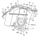
以下、本発明の実施形態について、車両の座席に取り付けたロック解除装置を例に取り説明する。図1は、自動車等の車両に用いられる座席のシートバック1を示すものであり、シートバック1は、図示しないロック機構を介して車体に対して起立状態に固定されると共に、シートバック1の上部に設けた解除装置2(操作部、操作係部品)を乗員が操作することにより前記ロック機構が解除され、シートバック1が下方の回動軸1aを中心に回動可能になり、シートバック1を前方に倒すことができる、所謂可倒式シートである。
Hereinafter, an embodiment of the present invention will be described taking an example of an unlocking device attached to a vehicle seat. FIG. 1 shows a
解除装置2は、図3に示すように、シートバック1上部の車体前方寄りに設けられ、解除機構を操作するためのノブ3(レバー)、ノブ3を収容しかつ回動軸31を中心に回動可能に支持する箱状のケース4、ノブ3の周囲を覆いケース4に固定されるベゼル5から主に構成されている。そして、乗員がノブ3の窪み30に手指を掛け該ノブ3を矢印Xのように車両前後方向の前側に回動させることにより、ノブ3に図示しないロッド等を介して連結されているロック機構が解除されるようになっている。以下、解除装置2のシートバック1への取付け構造について、図4〜図7を参照しながら説明する。
As shown in FIG. 3, the
ケース4は、有底の四角筒状をなし、上面開口部40からノブ3や図示しない内部機構を収容可能に構成されている。ケース4の上面開口部40は、設置部分のシートバック1の形状に合わせて略中央から前側が前方に傾斜し、前側の上端縁が低く形成されている。そして上面開口部40の周囲には、ベゼル5を固定するための複数の係止部41が側方に突設されている。
The
また、上面開口部40の周囲には複数の突片42が立設され、前記突片42の先端に係止爪42aが設けられている。さらに上面開口部40の周囲には側方に張出した棚面43が設けられている。なお、前記複数の突片42のうち、ケース4の後側および両側の突片42は、棚面43の端縁部に立設されている。また、ケース4の側面には、前記上面開口部40または棚面43から離間して受け面44が設けられている
A plurality of projecting
ケース4の底部にはブロック状の凸部45が突設され、該凸部45の車両前後方向の前面と両側面には、それぞれ係止爪45a,45bが突設されている。このうち両側面の係止爪45bは、前記側面に設けた開口部45c内に張出した弾性片に突設され、凸部45の内部に没入可能である。また、ケース4の内側面の下方には、支持孔46,46が対向して設けられ、該支持孔46,46も前記同様に弾性片に穿設され、ケース4外方に拡開可能であり、ノブ3の図示しない軸部を圧入可能である。これら弾性片の構成にはケース4が樹脂材を用いた成形品で形成されることが好ましい。解除装置2を構成する他の部品、ノブ3、ベゼル5も同様である。
Block-shaped
ベゼル5はケース4の上面開口部40の周囲を覆う枠状をなすと共に、該ベゼル5の車両前後方向における後側の辺部からケース4の内部に向かって垂れ下がる垂下片50が形成されている。また、ベゼル5の下面には、前記ケース4の複数の係止部41に対応して複数の被係止部51が突設されている。前記複数の被係止部51のうち、前側以外の各被係止部51は弾性片で構成され、外方に拡開可能である。
The
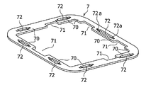
一方、表皮材6の開口部60の端縁には、ベゼル5の形状に合わせて矩形の枠状をなす補強部材7が固定されている。補強部材7は樹脂などの扁平な可撓性シート材から構成され、図4、5に示すように、前記開口部60の端縁から開口部60内に張出した張出部70に、ケース4の前記突片42に対応した配置でスリット72が穿設されている。さらに該スリット72の両端部には、前記突片42の係止爪42aに対応した幅狭部72aが形成されている。また、前記張出部70の間には、ケース4の前記係止部41に対応した配置で切欠き部71が設けられている。
On the other hand, a reinforcing
補強部材7は、解除装置2の取付け先立ち、表皮材6の縫製工程で予め縫製により取付けられる。補強部材7を縫製にて表皮材6に固定する場合は、補強部材7と表皮材6が重なる縫い代を設け、縫製ライン61の強度を確保するようにする。なお、縫製以外に溶着等により表皮材6に補強部材7を固定しても良い。
The reinforcing
次に、上記実施形態に基づき解除装置2のシートバック1への取付け過程および取付け構造について説明する。
Next, the attachment process and attachment structure of the
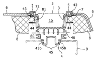
ノブ3および内部機構を組み付けたケース4は、図6及び図7に示すように、底部の凸部45をシートバック1のシートフレーム9に設けた取付け穴95に嵌入し、凸部45の側面の係止爪45a,45bを前記取付け穴95の縁に係止することによりシートフレーム9に固定される。次いで、クッション材8の開口部80をケース4に合わせ、クッション材8でシートフレーム9を覆うようにして該クッション材8をシートフレーム9に組付ける。この際、図7に示すように、クッション材8の突出部81をケース4の棚面43と受け面44との間に挟み込み挟持させる。
As shown in FIGS. 6 and 7, the
次いで、図4及び図6に示すように、補強部材7を固定した表皮材6の開口部60をケース4の上面開口部40に合わせ、補強部材7のスリット72をケース4の突片42に嵌合し、突片42の係止爪42aでスリット72の幅狭部72aを係止して表皮材6を位置決めすると共に、ケース4に固定する。
Next, as shown in FIGS. 4 and 6, the
そして、ベゼル5の被係止部51を切欠き部71に通して係止部41に係止し、ベゼル5の下面とケース4の棚面43とで表皮材6の縁部及び補強部材7を挟持した状態で、ベゼル5をケース4に固定する。これによりノブ3およびケース4の周囲と表皮材6の縁部とがベゼル5により覆われる。
Then, the locked
以上のようにしてシートバック1に取付けられた解除装置2は、補強部材7がケース4の突片42に係合することで表皮材6が位置決めされるとともに、ケース4に固定されるので、表皮材6の取付け作業を容易かつ確実に行うことができる。従来、表皮材6には乗員の着座時やノブ3の操作時の荷重が負荷され、さらに表皮材6そのものの伸びによりベゼル5の外周付近で引張されやすいが、補強部材7とケース4の突片42の係合により、表皮材6の端部がベゼル5からはみ出したり、表皮材6が落ち込んだりするのが防止され、取付け部付近の外観が向上する。
In the
更に、図6に示すように、ケース4の棚面43とベゼル5の下面(端縁部)とで、表皮材6及び補強部材7を両面から挟み込むように押さえ、突片42がスリット72に挿通された状態で固定されるので、表皮材6の端のめくれが防止されるとともに、曲面意匠への追従性が良好であり、その点からも取付け部付近の外観が向上する。更に、図6、図7に示すように、ケース4の側面において、棚面44でクッション材8の突出部81を受けることができ、ケース4周辺でのクッション材8の落ち込みが防止され、取付け部付近の外観が向上する。また、従来のように枠材等の別部品を溶接等で固定する必要が無く、少ない部品点数で、操作系部品2の周囲のクッション材8や表皮材6の形状を確実に保持し、外観の向上を可能とすることができる。
Further, as shown in FIG. 6, the
上記実施形態においては、ケース4をシートフレーム9の取付け穴95に嵌入し、係止爪45a,45bを取付け穴95の縁に係止することにより固定する場合を示したが、ケース4は、スクリュー等でシートフレーム9に固定されてもよい。また、ケース4と表皮材6とが補強部材7を介して強固に固定されるので、取付ける操作系部品の種類によっては、操作系部品(ケース4)が特にシートフレーム9などに固定されていなくてもよい。さらに上記実施形態においては、突片42に係止爪42aを設ける場合を示したが、係止爪42aを省略することもできる。特に、実施形態の解除装置2の場合、シートバック1の上面から前面にかけての湾曲面に設けられ、前端側と後端側の突片42がやや背向して突出しているので、それを利用して係止することもできる。但し、突片42に係止爪42aを設けることで係止力が増加し、補強部材7に強度および弾性が大きい素材を用いた場合にも確実に係止することができる利点がある。
In the above embodiment, the
以上、本発明の一実施形態について述べたが、本発明は上記実施形態に限定されるものではなく、本発明の技術的思想に基づいて各種の変形および変更が可能である。 As mentioned above, although one Embodiment of this invention was described, this invention is not limited to the said embodiment, Various deformation | transformation and a change are possible based on the technical idea of this invention.
1 シートバック
1a 回動軸
2 解除装置(操作系部品)
3 ノブ(操作部材)
30 窪み
31 回動軸
4 ケース
40 上面開口部
41 係止部
42 突片
42a 係止爪
43 棚面
44 受け面
45 凸部
45a,45b 係止爪
45c 開口部
46 支持孔
5 ベゼル
50 垂下片
51 被係止部
6 表皮材
60 開口部
61 縫製ライン
7 補強部材
70 張出部
71 切欠き部
72 スリット
72a 幅狭部
8 クッション材
80 開口部
81 突出部
9 シートフレーム
95 取付け穴
1 Seat back
3 Knob (operation member)
30
Claims (4)
前記操作系部品は、上面に開口部を設けた箱状のケースと、前記ケースに収容された操作部材と、該操作部材の周囲の前記ケース開口部を覆うベゼルとを備え、
前記ケース開口部には突片が立設され、前記表皮材の前記開口部の周囲には可撓性シート材からなる枠状の補強部材が設けられ、該補強部材には前記突片に対応した配置でスリットが穿設されており、
前記突片を前記スリットに挿通して前記補強部材を前記ケースの周囲に係止し、さらに、前記係止箇所の周囲で前記表皮材に前記ベゼルの外周縁を当接させ、前記表皮材および前記補強部材を前記ベゼルと前記ケースとで挟持した状態で、前記ベゼルを前記ケースに固定したことを特徴とする座席への操作系部品の取付け構造。 A seat provided with a frame, a cushion material covering the frame, and a skin material covering the surface of the cushion material, and an operation system component is attached to the frame through an opening provided in the skin material and the cushion material In the mounting structure of operation system parts to
The operation system component includes a box-shaped case having an opening on the upper surface, an operation member accommodated in the case, and a bezel that covers the case opening around the operation member,
A protruding piece is erected at the case opening, and a frame-shaped reinforcing member made of a flexible sheet material is provided around the opening of the skin material, and the reinforcing member corresponds to the protruding piece. A slit is drilled in the arrangement
The protruding piece is inserted into the slit to lock the reinforcing member around the case, and further, the outer peripheral edge of the bezel is brought into contact with the skin material around the locking portion, and the skin material and A structure for mounting an operation system component to a seat, wherein the bezel is fixed to the case in a state where the reinforcing member is sandwiched between the bezel and the case.
Priority Applications (1)
| Application Number | Priority Date | Filing Date | Title |
|---|---|---|---|
| JP2005327032A JP4779583B2 (en) | 2005-11-11 | 2005-11-11 | Mounting structure of operation parts to the seat |
Applications Claiming Priority (1)
| Application Number | Priority Date | Filing Date | Title |
|---|---|---|---|
| JP2005327032A JP4779583B2 (en) | 2005-11-11 | 2005-11-11 | Mounting structure of operation parts to the seat |
Publications (2)
| Publication Number | Publication Date |
|---|---|
| JP2007131199A JP2007131199A (en) | 2007-05-31 |
| JP4779583B2 true JP4779583B2 (en) | 2011-09-28 |
Family
ID=38153205
Family Applications (1)
| Application Number | Title | Priority Date | Filing Date |
|---|---|---|---|
| JP2005327032A Active JP4779583B2 (en) | 2005-11-11 | 2005-11-11 | Mounting structure of operation parts to the seat |
Country Status (1)
| Country | Link |
|---|---|
| JP (1) | JP4779583B2 (en) |
Cited By (1)
| Publication number | Priority date | Publication date | Assignee | Title |
|---|---|---|---|---|
| JP2020069086A (en) * | 2018-10-31 | 2020-05-07 | タカノ株式会社 | Mounting structure of optional member of chair, and chair |
Families Citing this family (15)
| Publication number | Priority date | Publication date | Assignee | Title |
|---|---|---|---|---|
| JP5239478B2 (en) * | 2007-09-20 | 2013-07-17 | トヨタ車体株式会社 | Vehicle seat |
| JP5414111B2 (en) * | 2009-09-24 | 2014-02-12 | スズキ株式会社 | Sheet |
| JP5499676B2 (en) * | 2009-12-14 | 2014-05-21 | トヨタ紡織株式会社 | Vehicle seat |
| JP5229832B2 (en) | 2010-12-22 | 2013-07-03 | トヨタ紡織株式会社 | Vehicle seat |
| JP6180268B2 (en) * | 2013-10-01 | 2017-08-16 | 株式会社タチエス | Vehicle seat |
| JP6551186B2 (en) * | 2015-11-20 | 2019-07-31 | テイ・エス テック株式会社 | Vehicle seat |
| JP6587546B2 (en) * | 2016-01-21 | 2019-10-09 | 日本発條株式会社 | Skin material mounting structure |
| JP6729070B2 (en) * | 2016-06-28 | 2020-07-22 | トヨタ紡織株式会社 | Vehicle seat |
| JP6291607B1 (en) * | 2017-03-10 | 2018-03-14 | 日本発條株式会社 | Lock release lever mounting structure |
| JP6947965B2 (en) * | 2017-04-04 | 2021-10-13 | テイ・エス テック株式会社 | Seat |
| JP7184532B2 (en) * | 2018-04-17 | 2022-12-06 | 株式会社タチエス | vehicle seat |
| JP7056522B2 (en) * | 2018-11-13 | 2022-04-19 | トヨタ紡織株式会社 | Vehicle seat |
| JP7306688B2 (en) * | 2019-09-03 | 2023-07-11 | デルタ工業株式会社 | seat |
| JP7354812B2 (en) * | 2019-12-05 | 2023-10-03 | トヨタ紡織株式会社 | mounting frame |
| DE102022113437A1 (en) * | 2021-05-28 | 2022-12-01 | Lear Corporation | fairing retainer |
-
2005
- 2005-11-11 JP JP2005327032A patent/JP4779583B2/en active Active
Cited By (1)
| Publication number | Priority date | Publication date | Assignee | Title |
|---|---|---|---|---|
| JP2020069086A (en) * | 2018-10-31 | 2020-05-07 | タカノ株式会社 | Mounting structure of optional member of chair, and chair |
Also Published As
| Publication number | Publication date |
|---|---|
| JP2007131199A (en) | 2007-05-31 |
Similar Documents
| Publication | Publication Date | Title |
|---|---|---|
| JP4779583B2 (en) | Mounting structure of operation parts to the seat | |
| EP2899064B1 (en) | Vehicle latch device | |
| JPH10250433A (en) | Mounting/demounting mechanism for vehicular seat | |
| EP3653430B1 (en) | Seat lock device | |
| EP2476583B1 (en) | Vehicle seat stowing device | |
| WO2018139332A1 (en) | Hook device | |
| JP5878321B2 (en) | Leg cover and vehicle seat provided with the leg cover | |
| JP2013095272A (en) | Vehicle seat with flip-up seat locking mechanism | |
| JP2020069891A (en) | Hook device | |
| JP6583749B2 (en) | Hook device | |
| JP6984330B2 (en) | Mounting structure of interior parts | |
| JP5421754B2 (en) | Interior structure for vehicles | |
| JP5248835B2 (en) | Slide lever mounting structure for vehicle seat cushion | |
| JP5088877B2 (en) | Luggage hanging device for vehicles | |
| JP6646238B2 (en) | Vehicle seat | |
| JP6334309B2 (en) | Headrest and seat | |
| JP5216728B2 (en) | Vehicle seat | |
| JP2001071819A (en) | Small article storage device at cabin front end of automobile | |
| JP2004106657A (en) | Active headrest structure | |
| JP2002264756A (en) | Air bag device | |
| JP2006298177A (en) | Lid mounting structure of latch cover for seat | |
| JP2006117072A (en) | Release lever device for vehicle seat | |
| JP2020066351A (en) | Vehicle seat | |
| JP3414622B2 (en) | Seat structure | |
| JP5016336B2 (en) | Lock structure of vehicle storage device |
Legal Events
| Date | Code | Title | Description |
|---|---|---|---|
| A621 | Written request for application examination |
Free format text: JAPANESE INTERMEDIATE CODE: A621 Effective date: 20081016 |
|
| A977 | Report on retrieval |
Free format text: JAPANESE INTERMEDIATE CODE: A971007 Effective date: 20110530 |
|
| TRDD | Decision of grant or rejection written | ||
| A01 | Written decision to grant a patent or to grant a registration (utility model) |
Free format text: JAPANESE INTERMEDIATE CODE: A01 Effective date: 20110607 |
|
| A01 | Written decision to grant a patent or to grant a registration (utility model) |
Free format text: JAPANESE INTERMEDIATE CODE: A01 |
|
| A61 | First payment of annual fees (during grant procedure) |
Free format text: JAPANESE INTERMEDIATE CODE: A61 Effective date: 20110620 |
|
| FPAY | Renewal fee payment (event date is renewal date of database) |
Free format text: PAYMENT UNTIL: 20140715 Year of fee payment: 3 |
|
| R151 | Written notification of patent or utility model registration |
Ref document number: 4779583 Country of ref document: JP Free format text: JAPANESE INTERMEDIATE CODE: R151 |
|
| FPAY | Renewal fee payment (event date is renewal date of database) |
Free format text: PAYMENT UNTIL: 20140715 Year of fee payment: 3 |