EP2898348B1 - Fotoelektronenvervielfachervorrichtung und strahlungsdetektor mit solch einer vorrichtung - Google Patents
Fotoelektronenvervielfachervorrichtung und strahlungsdetektor mit solch einer vorrichtung Download PDFInfo
- Publication number
- EP2898348B1 EP2898348B1 EP13766651.7A EP13766651A EP2898348B1 EP 2898348 B1 EP2898348 B1 EP 2898348B1 EP 13766651 A EP13766651 A EP 13766651A EP 2898348 B1 EP2898348 B1 EP 2898348B1
- Authority
- EP
- European Patent Office
- Prior art keywords
- photomultiplier
- window
- housing
- optical coupling
- scintillator
- Prior art date
- Legal status (The legal status is an assumption and is not a legal conclusion. Google has not performed a legal analysis and makes no representation as to the accuracy of the status listed.)
- Active
Links
Images



Classifications
-
- G—PHYSICS
- G01—MEASURING; TESTING
- G01T—MEASUREMENT OF NUCLEAR OR X-RADIATION
- G01T1/00—Measuring X-radiation, gamma radiation, corpuscular radiation, or cosmic radiation
- G01T1/16—Measuring radiation intensity
- G01T1/20—Measuring radiation intensity with scintillation detectors
- G01T1/202—Measuring radiation intensity with scintillation detectors the detector being a crystal
-
- G—PHYSICS
- G01—MEASURING; TESTING
- G01J—MEASUREMENT OF INTENSITY, VELOCITY, SPECTRAL CONTENT, POLARISATION, PHASE OR PULSE CHARACTERISTICS OF INFRARED, VISIBLE OR ULTRAVIOLET LIGHT; COLORIMETRY; RADIATION PYROMETRY
- G01J1/00—Photometry, e.g. photographic exposure meter
- G01J1/10—Photometry, e.g. photographic exposure meter by comparison with reference light or electric value provisionally void
- G01J1/20—Photometry, e.g. photographic exposure meter by comparison with reference light or electric value provisionally void intensity of the measured or reference value being varied to equalise their effects at the detectors, e.g. by varying incidence angle
-
- G—PHYSICS
- G01—MEASURING; TESTING
- G01T—MEASUREMENT OF NUCLEAR OR X-RADIATION
- G01T1/00—Measuring X-radiation, gamma radiation, corpuscular radiation, or cosmic radiation
- G01T1/16—Measuring radiation intensity
- G01T1/20—Measuring radiation intensity with scintillation detectors
- G01T1/2002—Optical details, e.g. reflecting or diffusing layers
-
- G—PHYSICS
- G01—MEASURING; TESTING
- G01T—MEASUREMENT OF NUCLEAR OR X-RADIATION
- G01T1/00—Measuring X-radiation, gamma radiation, corpuscular radiation, or cosmic radiation
- G01T1/16—Measuring radiation intensity
- G01T1/20—Measuring radiation intensity with scintillation detectors
- G01T1/208—Circuits specially adapted for scintillation detectors, e.g. for the photo-multiplier section
-
- G—PHYSICS
- G01—MEASURING; TESTING
- G01T—MEASUREMENT OF NUCLEAR OR X-RADIATION
- G01T7/00—Details of radiation-measuring instruments
-
- G—PHYSICS
- G01—MEASURING; TESTING
- G01V—GEOPHYSICS; GRAVITATIONAL MEASUREMENTS; DETECTING MASSES OR OBJECTS; TAGS
- G01V5/00—Prospecting or detecting by the use of ionising radiation, e.g. of natural or induced radioactivity
- G01V5/04—Prospecting or detecting by the use of ionising radiation, e.g. of natural or induced radioactivity specially adapted for well-logging
-
- H—ELECTRICITY
- H01—ELECTRIC ELEMENTS
- H01J—ELECTRIC DISCHARGE TUBES OR DISCHARGE LAMPS
- H01J43/00—Secondary-emission tubes; Electron-multiplier tubes
- H01J43/04—Electron multipliers
- H01J43/28—Vessels, e.g. wall of the tube; Windows; Screens; Suppressing undesired discharges or currents
-
- H—ELECTRICITY
- H01—ELECTRIC ELEMENTS
- H01J—ELECTRIC DISCHARGE TUBES OR DISCHARGE LAMPS
- H01J9/00—Apparatus or processes specially adapted for the manufacture, installation, removal, maintenance of electric discharge tubes, discharge lamps, or parts thereof; Recovery of material from discharge tubes or lamps
- H01J9/24—Manufacture or joining of vessels, leading-in conductors or bases
- H01J9/26—Sealing together parts of vessels
Definitions
- the present invention relates to a photomultiplier apparatus and to a radiation detector incorporating such apparatus, and relates particularly, but not exclusively, to a photomultiplier apparatus for use in a gamma radiation detector.
- a gamma detector for use in mining applications is disclosed in US2002/0056809 .
- the gamma detector has a scintillation element for converting gamma radiation into visible light, and a photomultiplier tube for converting visible light from the scintillation element into an electrical output signal.
- the scintillation element is mounted within a shield and emits visible light through an optical coupler, a window positioned at an end of the shield, through a further optical coupler and through a face of the photomultiplier tube (PMT).
- PMT photomultiplier tube
- a photomultiplier apparatus comprising: a first housing, window means, photomultiplier means, sealing means for isolating electrical terminals of said photomultiplier means from said window means, and resiliently deformable optical coupling means located between said window means and said photomultiplier means, wherein said resiliently deformable optical coupling means encapsulates an end of the photomultiplier means facing said window means.
- Preferred embodiments of the present invention seek to overcome the above disadvantage of the prior art.
- the photomultiplier means preferably comprises a photomultiplier tube.
- Photomultiplier tubes comprise electronic components for generating an electrical signal in proportion to light entering the PMT which are enclosed in a space surrounded by one or more sidewalls, an end cap typically including electrical terminals and an opposed end-face, typically made of glass, for example a borosilicate glass.
- the end face is the means by which light, e.g. from a scintillation element, enters the PMT so that the PMT can generate a current dependent on the amount of light entering through the end face.
- the end face is typically fragile and, if the end face is breached, the electrical components inside the PMT become exposed to the atmosphere.
- the photomultiplier apparatus When the photomultiplier apparatus is intended for use in a hazardous atmosphere, where flammable gases are, or may be, present, the exposure of the electrical components of the PMT to such an atmosphere can cause an explosion.
- the PMT When the PMT is housed together with the scintillator within a housing, the PMT may be protected by various shock absorbing arrangements which are shown in the prior art. If, however, it is desired to provide the PMT in a separate housing, so that it may be coupled to different scintillators, it is important that the PMT is also protected in the absence of the scintillator. This enables the detector to remain safe for use in hazardous atmospheres even if the scintillator is removed from the detector or if the scintillator is broken.
- the photomultiplier apparatus is preferably suitable for use in a hazardous location, where potentially explosive gas mixtures may be present continuously or intermittently at some time during operation of the apparatus.
- the photomultiplier apparatus is therefore preferably designed to be an intrinsically safe electrical device, as defined by the appropriate standards including the current version of European Standard EN 60079:2009, especially parts 0, 10 and 11 thereof.
- Intrinsically safe has the meaning given in the standards. Intrinsically safe is a widely used term having a precise meaning that is understood by the skilled person. According to European Standard EN 60079:2009 and British Standard BS EN 60079-11:2012, intrinsic safety is a type of protection based on the restriction of electrical energy within equipment and of interconnecting wiring exposed to the explosive atmosphere to a level below that which can cause ignition by either sparking or heating effects.
- An intrinsically safe circuit is a circuit in which any spark or any thermal effect produced in the conditions specified in the standard, which include normal operation and specified fault conditions, is not capable of causing ignition of a given explosive atmosphere.
- An intrinsically safe electrical device is a device in which all of the electrical circuits are intrinsically safe circuits. The design and selection of components and the test criteria applied to such equipment is governed by national and international standards such as BS EN 60079-11:2012 and its related parts, including part 0 concerning general requirements for electrical equipment intended for use in explosive atmospheres.
- the photomultiplier apparatus conforms at least to Level of Protection ib of the standard, i.e.
- the photomultiplier apparatus conforms to Level of Protection ia of the standard, i.e. it is designed to be safe in use in explosive atmospheres when the circuit contains two countable faults as defined in section 5.2 of BS EN 60079-11:2012.
- Such protection is achieved by the use of components and construction methods which include, for example, the separation of parts of the circuits by minimum separation distances as set out in section 6.3 "Separation Distances" of BS EN 60079-11:2012.
- voltage transformer means is provided in said first housing for converting electrical power having a first mean voltage to electrical power having a second mean voltage, higher than said first mean voltage.
- connector means is provided for connecting said voltage transformer means to a power supply external to said first housing.
- sealing means isolates components having said second mean voltage in said first housing from the exterior of said first housing.
- the voltage transformer means may comprise at least one voltage multiplier. At least one said voltage multiplier may comprise a Cockcroft-Walton voltage multiplier.
- the apparatus may further comprise voltage regulator means for receiving electrical power from said connector means and supplying electrical power having said first mean voltage to said voltage transforming means.
- the apparatus may further comprise adjustment means for adjusting said second average voltage.
- the apparatus may further comprise signal processing means for processing an output signal from said photomultiplier means, and at least one capacitor for isolating terminals of said voltage transforming means having said second mean voltage from said signal processing means.
- This provides the advantage of enabling high voltage power supply terminals of the photomultiplier means to be isolated from signal processing means communicating with the exterior of the first housing, thereby enabling the apparatus to be made intrinsically safe.
- the optical coupling means encapsulates an end of the photomultiplier means facing said window means. This provides the advantage of making the photomultiplier apparatus more robust by providing a shock absorber between the window means and the photomultiplier means and also provides a physical barrier between the internal space of the PMT and the atmosphere in the event that the window is broken.
- the optical coupling means adheres to the end face of the PMT.
- the thickness of the optical coupling means covering the end-face of the photomultiplier means is preferably greater than 1mm and more preferably at least 2mm.
- the optical coupling means extends beyond the location of any join between the end face of the PMT and any other part of the PMT, for example the join between the end face and the side wall(s) of the PMT.
- the optical coupling means extends along a portion of the sidewall(s) of the PMT, most preferably along at least 10% of the length of the sidewalls in the direction of the longitudinal axis of the PMT.
- the optical coupling means adheres to the sidewalls of the PMT.
- the optical coupling means preferably comprises at least one mouldable material, more preferably a resilient soft, polymeric material.
- the optical coupling means allows at least some electromagnetic radiation of said first wavelength range passing through said window means to enter said photomultiplier means.
- the optical coupling means is transparent to radiation emitted by a scintillation element coupled to the photomultiplier apparatus.
- Suitable materials for the optical coupling means include silicone elastomers and other polymers such as ethylene-vinyl acetate (eva) copolymers. Suitable silicone elastomers are already known for providing resilient lenses and optical coupling disks and a range of such materials is readily available commercially, for example from Momentive Performance Materials or Dow Corning.
- the photomultiplier apparatus of the invention includes sealing means for isolating electrical terminals of the photomultiplier means from the window means.
- the sealing means may form a gas-tight barrier to prevent contact between the surrounding atmosphere and said electrical terminals in the event that the window is broken.
- the sealing means may comprise one or more gaskets or O-rings to provide a gas-tight seal between the PMT and the housing.
- the sealing means comprises an electrically insulating material which encapsulates at least some of the electrical terminals of the photomultiplier apparatus.
- the electrically insulating material may, at least partly, encapsulate the photomultiplier means.
- the optical coupling means extends along a part of the sidewall of the photomultiplier means
- the electrically insulating material overlaps the optical coupling means, at least partially, so that the photomultiplier means is completely encapsulated by the sealing means and the optical coupling means.
- the sealing means may be adapted to resist transmission of electromagnetic radiation in at least part of said first wavelength range.
- the sealing means is substantially opaque to said first wavelength range. This provides the advantage of minimising the amount of radiation of the first wavelength range reaching the photomultiplier means other than through the window means, which in turn improves the signal to noise ratio of the apparatus.
- the sealing means may comprise at least one mouldable material. At least one said mouldable material may comprise a silicone material.
- the sealing means in the form of an encapsulating electrically insulating material may be formed from similar materials to the optical coupling means with the inclusion of opacifiers such as dyes, pigments or fillers.
- the first housing normally includes a first material having smaller transmissability to electromagnetic radiation of said first wavelength range than said window means, and is preferably opaque to said radiation.
- the first material may comprise at least one metal or plastics material. Suitable metals include non-oxidising metals such as stainless steel. Suitable plastics include materials which dissipate static electricity and so are relatively unlikely to generate a spark at their surface. Such materials are specified in the standards, such as British Standard BS EN 60079-11:2012, for intrinsically safe electrical apparatus. According to another aspect of the present invention, there is provided a radiation detection apparatus as set forth in dependent claim 7.
- Ionising radiation which may be detected by the radiation detection apparatus includes electromagnetic radiation such as gamma, beta, alpha particles, neutrons and X-rays.
- the radiation detecting apparatus is suitable for detecting gamma radiation, at least.
- the scintillator means may comprise a scintillation crystal or an organic scintillator such as a plastic scintillator or a liquid scintillator.
- Such scintillators are well-known for use in detection of ionising radiation.
- Scintillation crystals useful in the present apparatus include any of the currently known scintillation crystals including, for example, sodium iodide, zinc sulphide and caesium iodide amongst many others.
- Plastic scintillators are widely used in radiation detectors and they may be formed into any suitable shape or size. Typical plastic scintillators are in the form of an elongate rod which may have a length from a few mm to greater than 1m.
- the scintillator means may comprise a second housing comprising a second material having greater transmissability than said first material to the ionising radiation.
- the second housing protects the scintillator means from the atmosphere, but is selected to allow the ionising radiation which is to be detected by the detector to pass through the housing to the scintillator.
- the scintillator means or the housing may be provided with a reflective coating in order to reduce or prevent loss of light from the scintillator means, other than to the photomultiplier means.
- the scintillator means or said second housing includes means for mechanically coupling the scintillator means to the first housing such that the scintillator means is optically coupled to the window means of said photomultiplier apparatus.
- the mechanical coupling means is preferably releasable so that the scintillator means and the photomultiplier means may be coupled together and decoupled.
- the mechanical coupling means must provide a light-tight seal between the first and second housings so that light is prevented from entering the photomultiplier means, with the exception of light from the scintillator means.
- Suitable coupling means may include co--operatively threaded portions provided on the second housing and the first housing, a bayonet-type coupling between the first and second housings or an arrangement of fixing points which are coupled by means of screws, bolts or clips. It is a particular benefit of the radiation detector means of the invention that the photomultiplier apparatus is intrinsically safe, even in the absence of the scintillator means, so that loss or breakage of the scintillator means does not compromise the intrinsic safety of the apparatus.
- the scintillator means may be optically coupled to the window means of the photomultiplier apparatus by means of a pad or disk of resilient transparent material or by an optical-coupling grease, typically a silicone grease.
- the step of forming said assembly may comprise locating said photomultiplier means and said window means in position relative to each other and moulding said optical coupling means therebetween.
- the method may include locating the photomultiplier means and window means relative to each other in a jig.
- the step of providing the sealing means may comprise at least partially filing the housing with at least one electrically-insulating mouldable material.
- the radiation detector apparatus may be used to monitor ambient radiation or may be used to count radiation from a particular source, such as those used in a level gauge.
- the intrinsically safe design of the radiation detector makes it particularly suitable for use in hazardous areas, where a potentially explosive or flammable atmosphere may be present.
- the radiation detector may be used in pipelines, for example oil and gas pipelines.
- a gamma detection apparatus 2 comprises a photomultiplier unit 4 mountable by means of a cable gland inside a pipe (not shown) to be monitored, and a scintillator unit 8.
- the photomultiplier unit has rugged plastic handle rings 5.
- the scintillator unit 8 has a nylon housing 10 having strengthening ribs 12, and contains a sodium iodide or caesium iodide crystal 14 for converting gamma radiation into visible light in the wavelength range 300nm to 700nm.
- the crystal 14 is mounted to the housing 10 by means of a foam thrust cushion 16, a conductive O-ring 17 and a scintillator cage 18 made of phosphor bronze or stainless steel.
- the photomultiplier unit 4 has a rigid housing 20 of material opaque to visible light, which, in this embodiment is stainless steel and defining an aperture 22 at one end of which an assembly comprising a photomultiplier tube 24, a glass window 26 and a resiliently deformable optical coupling 28, in the form of a silicone casting compound moulded between the photomultiplier tube 24 and glass window 26, is mounted.
- the other end is closed by an end cap 6 which includes a cable gland.
- the optical coupling 28 is generally transparent to light in the wavelength range emitted by the crystal 14.
- the photomultiplier tube 24 converts visible light, passing from the scintillator unit 8 through the glass window 26, into an electrical output signal.
- the operation of the photomultiplier tube 24 will be familiar to persons skilled in the art and will therefore not be described in further detail herein.
- the scintillator unit 8 and photomultiplier unit 4 include co-operatively threaded portions 9a and 9b by which means the scintillator unit and photomultiplier unit may be coupled together so as to bring the crystal 14 into contact, preferably via an optical coupler, with the window 26.
- the photomultiplier tube 24 and glass window 26 are positioned in a mould 30 such that they are separated from each other, and then mouldable silicone casting material is injected into gap 32 between the photomultiplier tube 24 and window 26 to form the deformable optical coupling 28.
- the optical coupling 28 when set forms an airtight seal and has a volume resistivity of the order of 1.8 x 10 15 Ohm.cm in order to ensure that in the event of breaking of the window 26, electrical current is prevented from flowing to high voltage contacts of the photomultiplier tube 24 (described in greater detail below) from the atmosphere outside of the housing 20.
- the optical coupling 28 when set has sufficient hardness to protect the photomultiplier tube 24 and its associated electronics, for example a shore hardness of 44A.
- the assembly comprising the photomultiplier tube 24, window 26 and optical coupling 28 is then mounted to the housing 20 so that the window 26 closes aperture 22.
- Sealing means 56 comprising an opaque silicone moulding compound, may then be filled into said housing partly covering the optical coupling previously formed.
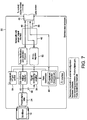
- photomultiplier tube 24 has high voltage output terminals 34 ( Figure 2 ) connected via a capacitor 36 to a signal conditioning amplifier 38 so that the high voltage photomultiplier terminals are isolated from the low voltage amplifier 38.
- the amplifier 38 provides an output pulse dependent on the intensity of visible light received by the photomultiplier tube 24 to a pulse discriminator 40 which is then provided to a low voltage power/signal interface 42 connected to output terminals 44 in output connector 46 located at the end of the housing 20 remote from the glass window 26.
- the connector 46 also has power supply terminal 48 providing 9V DC power via the power/signal interface 42 to a probe supply printed circuit board having a 5V DC regulator 50, which supplies an output voltage to a 500-1000V DC voltage multiplier 52 such as a Cockcroft Walton voltage multiplier, which will be familiar to persons skilled in the art, for supplying a high voltage supply to the photomultiplier tube 24, and a digital potentiometer high voltage gain control 54 for setting the output voltage of the voltage multiplier 52.
- a 500-1000V DC voltage multiplier 52 such as a Cockcroft Walton voltage multiplier, which will be familiar to persons skilled in the art, for supplying a high voltage supply to the photomultiplier tube 24, and a digital potentiometer high voltage gain control 54 for setting the output voltage of the voltage multiplier 52.
- the housing 20 When the processing electronics shown in Figure 7 is located in the housing 20, the housing 20 is filled with light absorbing silicone casting material 56, similar to the material used to form the optical coupling 28, but generally opaque to light in the wavelength range emitted by the crystal 14, for minimising the amount of stray light reaching the photomultiplier tube 24. This improves the signal to noise ratio of the photomultiplier tube 24.
- the silicone casting material 56 encapsulates those parts of the photomultiplier tube 24 not encapsulated by the optical coupling 28, and forms an airtight seal between the housing and the window 26, so that in the event of breaking of the window 26, the atmosphere surrounding the housing is prevented from coming into contact with high voltage terminals of the photomultiplier tube 24.
Landscapes
- Physics & Mathematics (AREA)
- General Physics & Mathematics (AREA)
- Spectroscopy & Molecular Physics (AREA)
- High Energy & Nuclear Physics (AREA)
- Life Sciences & Earth Sciences (AREA)
- Health & Medical Sciences (AREA)
- Molecular Biology (AREA)
- Engineering & Computer Science (AREA)
- Manufacturing & Machinery (AREA)
- Geophysics (AREA)
- General Life Sciences & Earth Sciences (AREA)
- Chemical & Material Sciences (AREA)
- Crystallography & Structural Chemistry (AREA)
- Measurement Of Radiation (AREA)
Claims (14)
- Photovervielfachervorrichtung (4), umfassend:a. ein erstes Gehäuse (20);b. Fenstermittel (26), die in das erste Gehäuse eingebaut sind, wobei die Fenstermittel mindestens teilweise für die elektromagnetische Strahlung eines ersten Wellenlängenbereichs durchlässig sind;c. Photovervielfachermittel (24), die im ersten Gehäuse für den Empfang elektromagnetischer Strahlung des ersten Wellenlängenbereichs bereitgestellt werden, die durch die Fenstermittel gelangt und ein elektrisches Ausgangssignal erzeugt, das von der Intensität der elektromagnetischen Strahlung abhängig ist;d. Abdichtungsmittel (56) zum Trennen der elektrischen Anschlüsse der Photovervielfachermittel von den Fenstermitteln; unde. elastisch verformbare optische Kopplungsmittel (28), die zwischen den Fenstermitteln und den Photovervielfachermitteln angeordnet sind, damit mindestens ein gewisser Teil der elektromagnetischen Strahlung des ersten Wellenlängenbereichs durch die Fenstermittel gelangt, um in die Photovervielfachermittel einzutreten, wobei die elastisch verformbaren optischen Kopplungsmittel ein Ende der Photovervielfachermittel, das zu den Fenstermitteln zeigt, einkapselndadurch gekennzeichnet, dass die elastisch verformbaren optischen Kopplungsmittel sich über einen Teil einer Seitenwand der Photovervielfachermittel erstrecken und dass die Abdichtungsmittel ein elektrisch isolierendes Material umfassen, das mindestens einige der elektrischen Anschlüsse der Photovervielfachervorrichtung einkapselt und das mindestens teilweise die optischen Kopplungsmittel so überlappt, dass die Photovervielfachermittel von den Abdichtungsmitteln und den optischen Kopplungsmitteln vollständig eingekapselt sind.
- Vorrichtung nach Anspruch 1, wobei die optischen Kopplungsmittel mindestens ein formbares Material umfassen.
- Vorrichtung nach einem der vorhergehenden Ansprüche, wobei die Abdichtungsmittel dafür ausgelegt sind, gegen die Durchlässigkeit der elektromagnetischen Strahlung in mindestens einem Teil des ersten Wellenlängenbereichs beständig zu sein.
- Vorrichtung nach einem der vorhergehenden Ansprüche, wobei die Abdichtungsmittel mindestens ein formbares Material umfassen.
- Vorrichtung nach einem der Ansprüche 2 bis 4, wobei mindestens ein formbares Material ein Silikonmaterial umfasst.
- Vorrichtung nach einem der vorhergehenden Ansprüche, wobei das erste Gehäuse ein erstes Material mit einem kleineren Durchlassungsvermögen für elektromagnetische Strahlung des ersten Wellenlängenbereichs als die Fenstermittel umfasst.
- Strahlungsdetektionsvorrichtung (2), umfassend:eine Photovervielfachervorrichtung nach einem der vorhergehenden Ansprüche; undSzintillatormittel (8) zur Umwandlung der ionisierenden Strahlung in elektromagnetische Strahlung des ersten Wellenlängenbereichs, wobei die Szintillatormittel optisch an die Fenstermittel der Photovervielfachervorrichtung gekoppelt sind.
- Vorrichtung nach Anspruch 7, wobei die Szintillatormittel ein zweites Gehäuse (10) mit einem zweiten Material umfassen, das in Bezug auf die ionisierende Strahlung ein größeres Durchlassungsvermögen als das erste Material aufweist.
- Vorrichtung nach Anspruch 7 oder 8, wobei die Szintillatormittel oder das zweite Gehäuse Mittel (9a, 9b) umfassen bzw. umfasst, um die Szintillatormittel mechanisch so an das erste Gehäuse zu koppeln, dass die Szintillatormittel optisch an die Fenstermittel der Photovervielfachervorrichtung gekoppelt sind.
- Vorrichtung nach einem der Ansprüche 7 - 9, wobei die mechanischen Kopplungsmittel so lösbar sind, dass die Szintillatormittel und die Photovervielfachermittel miteinander gekoppelt und voneinander entkoppelt werden können; und wobei die mechanischen Kopplungsmittel als Option zusammenwirkende Gewindeteile, die auf dem zweiten und dem ersten Gehäuse bereitgestellt werden, eine Bajonettkopplung zwischen dem ersten und zweiten Gehäuse oder eine Anordnung von Befestigungspunkten, die mittels Schrauben, Mutterschrauben oder Befestigungsklemmen gekoppelt sind, umfassen.
- Vorrichtung nach einem der Ansprüche 7 - 10, wobei die Photovervielfachervorrichtung beim Nichtvorhandensein der Szintillatormittel eigensicher ist.
- Verfahren zur Herstellung einer Photovervielfachervorrichtung, wobei das Verfahren die folgenden Schritte umfasst:a) Bilden einer Baueinheit, die optische Kopplungsmittel umfasst, die sich zwischen Photovervielfachermitteln und Fenstermitteln befinden, wobei die optischen Kopplungsmittel elastisch verformbar sind, sich längs eines Teils einer Seitenwand der Photovervielfachermittel erstrecken und ein Ende der Photovervielfachermittel, das zu den Fenstermitteln zeigt, einkapseln und wobei das Photovervielfachermittel dafür ausgelegt ist, elektromagnetische Strahlung eines ersten Wellenlängenbereichs zu empfangen, die durch die Fenstermittel gelangt und dadurch ein elektrisches Ausgangssignal erzeugt, das von der Intensität der elektromagnetischen Strahlung abhängig ist;b) Einbauen der Baueinheit in ein Gehäuse; undc) Bereitstellen von Abdichtungsmitteln zum Trennen der elektrischen Anschlüsse der Photovervielfachermittel von den Fenstermitteln, wobei die Abdichtungsmittel ein elektrisch isolierendes Material umfassen, das mindestens einen gewissen Teil der elektrischen Anschlüsse der Photovervielfachervorrichtung einkapselt und das mindestens teilweise so mit den optischen Kopplungsmitteln überlappt, dass die Photovervielfachermittel von den Abdichtungsmitteln und den optischen Kopplungsmitteln vollständig eingekapselt sind.
- Verfahren nach Anspruch 12, wobei der Schritt des Bildens der Baueinheit das Lokalisieren der relativen Lage der Photovervielfachermittel und der Fenstermittel zueinander und das Formen der optischen Koppelungsmittel zwischen denselben umfasst.
- Verfahren nach einem der Ansprüche 12 bis 13, wobei der Schritt der Bereitstellung der Abdichtungsmittel mindestens teilweise das Füllen des Gehäuses mit mindestens einem formbaren Material umfasst.
Applications Claiming Priority (3)
| Application Number | Priority Date | Filing Date | Title |
|---|---|---|---|
| US201261703805P | 2012-09-21 | 2012-09-21 | |
| GBGB1216850.6A GB201216850D0 (en) | 2012-09-21 | 2012-09-21 | Photomultiplier apparatus and radiation detector incorporating such apparatus |
| PCT/GB2013/052476 WO2014045058A1 (en) | 2012-09-21 | 2013-09-20 | Photomultiplier apparatus and radiation detector incorporating such apparatus |
Publications (2)
| Publication Number | Publication Date |
|---|---|
| EP2898348A1 EP2898348A1 (de) | 2015-07-29 |
| EP2898348B1 true EP2898348B1 (de) | 2020-01-01 |
Family
ID=47190367
Family Applications (1)
| Application Number | Title | Priority Date | Filing Date |
|---|---|---|---|
| EP13766651.7A Active EP2898348B1 (de) | 2012-09-21 | 2013-09-20 | Fotoelektronenvervielfachervorrichtung und strahlungsdetektor mit solch einer vorrichtung |
Country Status (6)
| Country | Link |
|---|---|
| US (1) | US9377538B2 (de) |
| EP (1) | EP2898348B1 (de) |
| AU (1) | AU2013320016B2 (de) |
| CA (1) | CA2885506C (de) |
| GB (2) | GB201216850D0 (de) |
| WO (1) | WO2014045058A1 (de) |
Families Citing this family (14)
| Publication number | Priority date | Publication date | Assignee | Title |
|---|---|---|---|---|
| RU2683798C2 (ru) * | 2014-05-03 | 2019-04-02 | Толтек Груп, Ллс | Защита детектора гамма-излучения для скважинных операций |
| ES2558177B1 (es) * | 2014-07-30 | 2016-09-09 | Tecnatom, S.A. | Detector de radiación gamma |
| WO2017158911A1 (ja) * | 2016-03-17 | 2017-09-21 | 株式会社日立製作所 | 放射線測定用プローブ |
| DE102016105385A1 (de) * | 2016-03-22 | 2017-09-28 | Vega Grieshaber Kg | Sensorgehäuse und Sensor mit Sensorgehäuse |
| RU170212U1 (ru) * | 2016-09-20 | 2017-04-18 | Общество с ограниченной ответственностью "ТехГеоБур" | Модуль гамма-каротажа |
| DE102016122049A1 (de) * | 2016-11-16 | 2018-05-17 | Endress+Hauser SE+Co. KG | Detektor-Einheit für ein radiometrisches Dichte- oder Füllstandsmessgerät |
| DE102017205758A1 (de) * | 2017-04-04 | 2018-10-04 | Vega Grieshaber Kg | Eigensicheres radiometrisches Messgerät im Kunststoffgehäuse |
| US10775515B2 (en) | 2017-10-24 | 2020-09-15 | Saint-Gobain Ceramics & Plastics, Inc. | Radiation detection apparatus having an analyzer within a housing |
| CN113167916A (zh) | 2018-11-30 | 2021-07-23 | 圣戈本陶瓷及塑料股份有限公司 | 具有反射器的辐射探测装置 |
| CN110265281B (zh) * | 2019-06-12 | 2020-07-17 | 中国科学院高能物理研究所 | 一种基于微通道板结构的光电倍增管的防水封装 |
| CN110389375A (zh) * | 2019-08-15 | 2019-10-29 | 广州技达教育科技有限公司 | 一种基于闪烁体的γ射线探测装置 |
| DE102020209901A1 (de) | 2020-08-05 | 2022-02-10 | Vega Grieshaber Kg | Radiometrisches Messgerät, Fensterelement und Verfahren zur Herstellung eines Fensterelements |
| CN111968906B (zh) * | 2020-09-14 | 2021-07-06 | 中国科学院高能物理研究所 | 光电倍增管的防油封装结构、光电倍增管及防油封装方法 |
| DE102023102241A1 (de) * | 2023-01-31 | 2024-08-01 | Vega Grieshaber Kg | Radiometrisches Messgerät mit optischem Pad und optisches Pad |
Family Cites Families (11)
| Publication number | Priority date | Publication date | Assignee | Title |
|---|---|---|---|---|
| DK96684A (da) * | 1983-05-24 | 1984-11-25 | Siemens Ag | Fremgangsmaade til i en straalingsdetektor udskifteligt at forbinde et fotomultiplikatorroer med en scintillationskrystal |
| US5548116A (en) * | 1994-03-01 | 1996-08-20 | Optoscint, Inc. | Long life oil well logging assembly |
| US5796109A (en) * | 1996-05-03 | 1998-08-18 | Frederick Energy Products | Unitized radiation detector assembly |
| US5869836A (en) * | 1996-09-20 | 1999-02-09 | Saint-Gobain Industrial Ceramics, Inc. | Scintillation detector with sleeved crystal boot |
| US6355932B1 (en) * | 1998-02-25 | 2002-03-12 | General Electric Company | Maximum volume ruggedized nuclear detector |
| US20020056809A1 (en) | 2000-10-06 | 2002-05-16 | Frederick Larry D. | Armored rock detector |
| US6465788B1 (en) * | 1999-12-23 | 2002-10-15 | Frederick Energy Products Llc | Ruggedized photomultiplier tube and optical coupling in armored detector |
| US6872937B2 (en) * | 2002-12-20 | 2005-03-29 | General Electric Company | Well logging apparatus with gadolinium optical interface |
| US7381957B2 (en) | 2004-08-05 | 2008-06-03 | Frederick Mining Controls | Compound optical coupler and support mechanism |
| US8987670B2 (en) | 2008-10-09 | 2015-03-24 | Schlumberger Technology Corporation | Thermally-protected scintillation detector |
| US8492705B2 (en) | 2009-10-23 | 2013-07-23 | Saint-Gobain Ceramics & Plastics, Inc. | Radiation detector and method of using a radiation detector |
-
2012
- 2012-09-21 GB GBGB1216850.6A patent/GB201216850D0/en not_active Ceased
-
2013
- 2013-09-20 AU AU2013320016A patent/AU2013320016B2/en active Active
- 2013-09-20 EP EP13766651.7A patent/EP2898348B1/de active Active
- 2013-09-20 US US14/429,821 patent/US9377538B2/en active Active
- 2013-09-20 WO PCT/GB2013/052476 patent/WO2014045058A1/en not_active Ceased
- 2013-09-20 GB GB1316792.9A patent/GB2508083B/en active Active
- 2013-09-20 CA CA2885506A patent/CA2885506C/en active Active
Non-Patent Citations (1)
| Title |
|---|
| None * |
Also Published As
| Publication number | Publication date |
|---|---|
| GB2508083A (en) | 2014-05-21 |
| GB2508083B (en) | 2016-01-06 |
| WO2014045058A1 (en) | 2014-03-27 |
| US20150234057A1 (en) | 2015-08-20 |
| US9377538B2 (en) | 2016-06-28 |
| GB201316792D0 (en) | 2013-11-06 |
| GB201216850D0 (en) | 2012-11-07 |
| AU2013320016B2 (en) | 2017-07-20 |
| EP2898348A1 (de) | 2015-07-29 |
| AU2013320016A1 (en) | 2015-04-02 |
| CA2885506C (en) | 2019-04-16 |
| CA2885506A1 (en) | 2014-03-27 |
Similar Documents
| Publication | Publication Date | Title |
|---|---|---|
| AU2013320016B2 (en) | Photomultiplier apparatus and radiation detector incorporating such apparatus | |
| US11391851B2 (en) | Sealed radiation detector module systems and methods | |
| US6359282B1 (en) | Modular radiation detector assembly | |
| US8069724B2 (en) | Filling level indicator having an explosion-proof housing | |
| CA2312593C (en) | Thermal neutron detector using a scintillator with background gamma-ray shielding | |
| US9158007B2 (en) | Scintillation detector | |
| US10451747B2 (en) | Radiation detector module systems and methods | |
| US11852756B2 (en) | Radiographic detector readout | |
| US8153981B2 (en) | Radiation detector assembly | |
| CN104755888B (zh) | 辐射检测器 | |
| WO2004088684A2 (en) | Flexible liquid-filled radiation detector scintillator | |
| US5256878A (en) | Self powered detector based monitor for radiographic cameras | |
| KR102554162B1 (ko) | 광전식 연기 감지기 | |
| CN102798879B (zh) | 用于伽马放射源定位仪的准直器 | |
| US3950647A (en) | Detection instrument for plutonium-americium | |
| CN110416057B (zh) | 光电倍增管屏蔽结构及信号检测装置 | |
| JP2019513237A (ja) | 一体型核センサ | |
| JP5356999B2 (ja) | 放射線検出器 | |
| CN120418616A (zh) | 带光学垫的辐射测量装置和光学垫 | |
| JP2013088381A (ja) | 携帯型放射線検出器 | |
| CN102830419B (zh) | 用于伽马放射源定位仪的探测器组件及其制造方法 | |
| JP5313855B2 (ja) | 放射性ガスモニタ | |
| US2995661A (en) | Radiation meter with shielded amplifier | |
| KR101450613B1 (ko) | 방사선 검출 장치 | |
| CN219016593U (zh) | 一种用于液体闪烁氚测量仪的抽屉式铅屏蔽体 |
Legal Events
| Date | Code | Title | Description |
|---|---|---|---|
| PUAI | Public reference made under article 153(3) epc to a published international application that has entered the european phase |
Free format text: ORIGINAL CODE: 0009012 |
|
| 17P | Request for examination filed |
Effective date: 20150401 |
|
| AK | Designated contracting states |
Kind code of ref document: A1 Designated state(s): AL AT BE BG CH CY CZ DE DK EE ES FI FR GB GR HR HU IE IS IT LI LT LU LV MC MK MT NL NO PL PT RO RS SE SI SK SM TR |
|
| AX | Request for extension of the european patent |
Extension state: BA ME |
|
| DAX | Request for extension of the european patent (deleted) | ||
| STAA | Information on the status of an ep patent application or granted ep patent |
Free format text: STATUS: EXAMINATION IS IN PROGRESS |
|
| 17Q | First examination report despatched |
Effective date: 20181017 |
|
| GRAP | Despatch of communication of intention to grant a patent |
Free format text: ORIGINAL CODE: EPIDOSNIGR1 |
|
| STAA | Information on the status of an ep patent application or granted ep patent |
Free format text: STATUS: GRANT OF PATENT IS INTENDED |
|
| INTG | Intention to grant announced |
Effective date: 20190823 |
|
| RIN1 | Information on inventor provided before grant (corrected) |
Inventor name: CUNNINGHAM, COLIN Inventor name: BROOKES, STEPHEN JOHN |
|
| GRAS | Grant fee paid |
Free format text: ORIGINAL CODE: EPIDOSNIGR3 |
|
| GRAA | (expected) grant |
Free format text: ORIGINAL CODE: 0009210 |
|
| STAA | Information on the status of an ep patent application or granted ep patent |
Free format text: STATUS: THE PATENT HAS BEEN GRANTED |
|
| AK | Designated contracting states |
Kind code of ref document: B1 Designated state(s): AL AT BE BG CH CY CZ DE DK EE ES FI FR GB GR HR HU IE IS IT LI LT LU LV MC MK MT NL NO PL PT RO RS SE SI SK SM TR |
|
| REG | Reference to a national code |
Ref country code: GB Ref legal event code: FG4D |
|
| REG | Reference to a national code |
Ref country code: CH Ref legal event code: EP Ref country code: AT Ref legal event code: REF Ref document number: 1220478 Country of ref document: AT Kind code of ref document: T Effective date: 20200115 |
|
| REG | Reference to a national code |
Ref country code: DE Ref legal event code: R096 Ref document number: 602013064626 Country of ref document: DE |
|
| REG | Reference to a national code |
Ref country code: IE Ref legal event code: FG4D |
|
| REG | Reference to a national code |
Ref country code: NL Ref legal event code: MP Effective date: 20200101 |
|
| REG | Reference to a national code |
Ref country code: LT Ref legal event code: MG4D |
|
| PG25 | Lapsed in a contracting state [announced via postgrant information from national office to epo] |
Ref country code: LT Free format text: LAPSE BECAUSE OF FAILURE TO SUBMIT A TRANSLATION OF THE DESCRIPTION OR TO PAY THE FEE WITHIN THE PRESCRIBED TIME-LIMIT Effective date: 20200101 Ref country code: NO Free format text: LAPSE BECAUSE OF FAILURE TO SUBMIT A TRANSLATION OF THE DESCRIPTION OR TO PAY THE FEE WITHIN THE PRESCRIBED TIME-LIMIT Effective date: 20200401 Ref country code: FI Free format text: LAPSE BECAUSE OF FAILURE TO SUBMIT A TRANSLATION OF THE DESCRIPTION OR TO PAY THE FEE WITHIN THE PRESCRIBED TIME-LIMIT Effective date: 20200101 Ref country code: NL Free format text: LAPSE BECAUSE OF FAILURE TO SUBMIT A TRANSLATION OF THE DESCRIPTION OR TO PAY THE FEE WITHIN THE PRESCRIBED TIME-LIMIT Effective date: 20200101 Ref country code: PT Free format text: LAPSE BECAUSE OF FAILURE TO SUBMIT A TRANSLATION OF THE DESCRIPTION OR TO PAY THE FEE WITHIN THE PRESCRIBED TIME-LIMIT Effective date: 20200527 Ref country code: CZ Free format text: LAPSE BECAUSE OF FAILURE TO SUBMIT A TRANSLATION OF THE DESCRIPTION OR TO PAY THE FEE WITHIN THE PRESCRIBED TIME-LIMIT Effective date: 20200101 Ref country code: RS Free format text: LAPSE BECAUSE OF FAILURE TO SUBMIT A TRANSLATION OF THE DESCRIPTION OR TO PAY THE FEE WITHIN THE PRESCRIBED TIME-LIMIT Effective date: 20200101 |
|
| PG25 | Lapsed in a contracting state [announced via postgrant information from national office to epo] |
Ref country code: SE Free format text: LAPSE BECAUSE OF FAILURE TO SUBMIT A TRANSLATION OF THE DESCRIPTION OR TO PAY THE FEE WITHIN THE PRESCRIBED TIME-LIMIT Effective date: 20200101 Ref country code: GR Free format text: LAPSE BECAUSE OF FAILURE TO SUBMIT A TRANSLATION OF THE DESCRIPTION OR TO PAY THE FEE WITHIN THE PRESCRIBED TIME-LIMIT Effective date: 20200402 Ref country code: LV Free format text: LAPSE BECAUSE OF FAILURE TO SUBMIT A TRANSLATION OF THE DESCRIPTION OR TO PAY THE FEE WITHIN THE PRESCRIBED TIME-LIMIT Effective date: 20200101 Ref country code: HR Free format text: LAPSE BECAUSE OF FAILURE TO SUBMIT A TRANSLATION OF THE DESCRIPTION OR TO PAY THE FEE WITHIN THE PRESCRIBED TIME-LIMIT Effective date: 20200101 Ref country code: IS Free format text: LAPSE BECAUSE OF FAILURE TO SUBMIT A TRANSLATION OF THE DESCRIPTION OR TO PAY THE FEE WITHIN THE PRESCRIBED TIME-LIMIT Effective date: 20200501 Ref country code: BG Free format text: LAPSE BECAUSE OF FAILURE TO SUBMIT A TRANSLATION OF THE DESCRIPTION OR TO PAY THE FEE WITHIN THE PRESCRIBED TIME-LIMIT Effective date: 20200401 |
|
| REG | Reference to a national code |
Ref country code: DE Ref legal event code: R097 Ref document number: 602013064626 Country of ref document: DE |
|
| PG25 | Lapsed in a contracting state [announced via postgrant information from national office to epo] |
Ref country code: ES Free format text: LAPSE BECAUSE OF FAILURE TO SUBMIT A TRANSLATION OF THE DESCRIPTION OR TO PAY THE FEE WITHIN THE PRESCRIBED TIME-LIMIT Effective date: 20200101 Ref country code: RO Free format text: LAPSE BECAUSE OF FAILURE TO SUBMIT A TRANSLATION OF THE DESCRIPTION OR TO PAY THE FEE WITHIN THE PRESCRIBED TIME-LIMIT Effective date: 20200101 Ref country code: DK Free format text: LAPSE BECAUSE OF FAILURE TO SUBMIT A TRANSLATION OF THE DESCRIPTION OR TO PAY THE FEE WITHIN THE PRESCRIBED TIME-LIMIT Effective date: 20200101 Ref country code: SM Free format text: LAPSE BECAUSE OF FAILURE TO SUBMIT A TRANSLATION OF THE DESCRIPTION OR TO PAY THE FEE WITHIN THE PRESCRIBED TIME-LIMIT Effective date: 20200101 Ref country code: EE Free format text: LAPSE BECAUSE OF FAILURE TO SUBMIT A TRANSLATION OF THE DESCRIPTION OR TO PAY THE FEE WITHIN THE PRESCRIBED TIME-LIMIT Effective date: 20200101 Ref country code: SK Free format text: LAPSE BECAUSE OF FAILURE TO SUBMIT A TRANSLATION OF THE DESCRIPTION OR TO PAY THE FEE WITHIN THE PRESCRIBED TIME-LIMIT Effective date: 20200101 |
|
| PLBE | No opposition filed within time limit |
Free format text: ORIGINAL CODE: 0009261 |
|
| STAA | Information on the status of an ep patent application or granted ep patent |
Free format text: STATUS: NO OPPOSITION FILED WITHIN TIME LIMIT |
|
| REG | Reference to a national code |
Ref country code: AT Ref legal event code: MK05 Ref document number: 1220478 Country of ref document: AT Kind code of ref document: T Effective date: 20200101 |
|
| 26N | No opposition filed |
Effective date: 20201002 |
|
| PG25 | Lapsed in a contracting state [announced via postgrant information from national office to epo] |
Ref country code: AT Free format text: LAPSE BECAUSE OF FAILURE TO SUBMIT A TRANSLATION OF THE DESCRIPTION OR TO PAY THE FEE WITHIN THE PRESCRIBED TIME-LIMIT Effective date: 20200101 Ref country code: IT Free format text: LAPSE BECAUSE OF FAILURE TO SUBMIT A TRANSLATION OF THE DESCRIPTION OR TO PAY THE FEE WITHIN THE PRESCRIBED TIME-LIMIT Effective date: 20200101 |
|
| PG25 | Lapsed in a contracting state [announced via postgrant information from national office to epo] |
Ref country code: SI Free format text: LAPSE BECAUSE OF FAILURE TO SUBMIT A TRANSLATION OF THE DESCRIPTION OR TO PAY THE FEE WITHIN THE PRESCRIBED TIME-LIMIT Effective date: 20200101 Ref country code: PL Free format text: LAPSE BECAUSE OF FAILURE TO SUBMIT A TRANSLATION OF THE DESCRIPTION OR TO PAY THE FEE WITHIN THE PRESCRIBED TIME-LIMIT Effective date: 20200101 |
|
| PG25 | Lapsed in a contracting state [announced via postgrant information from national office to epo] |
Ref country code: MC Free format text: LAPSE BECAUSE OF FAILURE TO SUBMIT A TRANSLATION OF THE DESCRIPTION OR TO PAY THE FEE WITHIN THE PRESCRIBED TIME-LIMIT Effective date: 20200101 |
|
| REG | Reference to a national code |
Ref country code: CH Ref legal event code: PL |
|
| GBPC | Gb: european patent ceased through non-payment of renewal fee |
Effective date: 20200920 |
|
| REG | Reference to a national code |
Ref country code: BE Ref legal event code: MM Effective date: 20200930 |
|
| PG25 | Lapsed in a contracting state [announced via postgrant information from national office to epo] |
Ref country code: LU Free format text: LAPSE BECAUSE OF NON-PAYMENT OF DUE FEES Effective date: 20200920 |
|
| PG25 | Lapsed in a contracting state [announced via postgrant information from national office to epo] |
Ref country code: IE Free format text: LAPSE BECAUSE OF NON-PAYMENT OF DUE FEES Effective date: 20200920 Ref country code: LI Free format text: LAPSE BECAUSE OF NON-PAYMENT OF DUE FEES Effective date: 20200930 Ref country code: GB Free format text: LAPSE BECAUSE OF NON-PAYMENT OF DUE FEES Effective date: 20200920 Ref country code: BE Free format text: LAPSE BECAUSE OF NON-PAYMENT OF DUE FEES Effective date: 20200930 Ref country code: CH Free format text: LAPSE BECAUSE OF NON-PAYMENT OF DUE FEES Effective date: 20200930 |
|
| PG25 | Lapsed in a contracting state [announced via postgrant information from national office to epo] |
Ref country code: TR Free format text: LAPSE BECAUSE OF FAILURE TO SUBMIT A TRANSLATION OF THE DESCRIPTION OR TO PAY THE FEE WITHIN THE PRESCRIBED TIME-LIMIT Effective date: 20200101 Ref country code: MT Free format text: LAPSE BECAUSE OF FAILURE TO SUBMIT A TRANSLATION OF THE DESCRIPTION OR TO PAY THE FEE WITHIN THE PRESCRIBED TIME-LIMIT Effective date: 20200101 Ref country code: CY Free format text: LAPSE BECAUSE OF FAILURE TO SUBMIT A TRANSLATION OF THE DESCRIPTION OR TO PAY THE FEE WITHIN THE PRESCRIBED TIME-LIMIT Effective date: 20200101 |
|
| PG25 | Lapsed in a contracting state [announced via postgrant information from national office to epo] |
Ref country code: MK Free format text: LAPSE BECAUSE OF FAILURE TO SUBMIT A TRANSLATION OF THE DESCRIPTION OR TO PAY THE FEE WITHIN THE PRESCRIBED TIME-LIMIT Effective date: 20200101 Ref country code: AL Free format text: LAPSE BECAUSE OF FAILURE TO SUBMIT A TRANSLATION OF THE DESCRIPTION OR TO PAY THE FEE WITHIN THE PRESCRIBED TIME-LIMIT Effective date: 20200101 |
|
| P01 | Opt-out of the competence of the unified patent court (upc) registered |
Effective date: 20230526 |
|
| REG | Reference to a national code |
Ref country code: DE Ref legal event code: R082 Ref document number: 602013064626 Country of ref document: DE Representative=s name: MURGITROYD GERMANY PATENTANWALTSGESELLSCHAFT M, DE |
|
| REG | Reference to a national code |
Ref country code: DE Ref legal event code: R081 Ref document number: 602013064626 Country of ref document: DE Owner name: TRACERCO LTD., GB Free format text: FORMER OWNER: JOHNSON MATTHEY PUBLIC LIMITED COMPANY, LONDON, GB |
|
| PGFP | Annual fee paid to national office [announced via postgrant information from national office to epo] |
Ref country code: DE Payment date: 20260220 Year of fee payment: 13 |
|
| PGFP | Annual fee paid to national office [announced via postgrant information from national office to epo] |
Ref country code: FR Payment date: 20260220 Year of fee payment: 13 |