EP2897304A1 - Procédés d'un premier et un second noeud de réseau d'accès radio permettant de configurer une transmission de fréquence radio à micro-ondes entre une première antenne et une seconde antenne hautement directionnelles, lesdits premier et second noeuds de réseau d'accès radio - Google Patents
Procédés d'un premier et un second noeud de réseau d'accès radio permettant de configurer une transmission de fréquence radio à micro-ondes entre une première antenne et une seconde antenne hautement directionnelles, lesdits premier et second noeuds de réseau d'accès radio Download PDFInfo
- Publication number
- EP2897304A1 EP2897304A1 EP14305078.9A EP14305078A EP2897304A1 EP 2897304 A1 EP2897304 A1 EP 2897304A1 EP 14305078 A EP14305078 A EP 14305078A EP 2897304 A1 EP2897304 A1 EP 2897304A1
- Authority
- EP
- European Patent Office
- Prior art keywords
- highly directional
- directional antenna
- antenna
- access network
- frequency range
- Prior art date
- Legal status (The legal status is an assumption and is not a legal conclusion. Google has not performed a legal analysis and makes no representation as to the accuracy of the status listed.)
- Withdrawn
Links
Images


Classifications
-
- H—ELECTRICITY
- H04—ELECTRIC COMMUNICATION TECHNIQUE
- H04B—TRANSMISSION
- H04B7/00—Radio transmission systems, i.e. using radiation field
- H04B7/02—Diversity systems; Multi-antenna system, i.e. transmission or reception using multiple antennas
- H04B7/04—Diversity systems; Multi-antenna system, i.e. transmission or reception using multiple antennas using two or more spaced independent antennas
- H04B7/06—Diversity systems; Multi-antenna system, i.e. transmission or reception using multiple antennas using two or more spaced independent antennas at the transmitting station
- H04B7/0686—Hybrid systems, i.e. switching and simultaneous transmission
- H04B7/0695—Hybrid systems, i.e. switching and simultaneous transmission using beam selection
-
- H—ELECTRICITY
- H04—ELECTRIC COMMUNICATION TECHNIQUE
- H04B—TRANSMISSION
- H04B7/00—Radio transmission systems, i.e. using radiation field
- H04B7/02—Diversity systems; Multi-antenna system, i.e. transmission or reception using multiple antennas
- H04B7/04—Diversity systems; Multi-antenna system, i.e. transmission or reception using multiple antennas using two or more spaced independent antennas
- H04B7/06—Diversity systems; Multi-antenna system, i.e. transmission or reception using multiple antennas using two or more spaced independent antennas at the transmitting station
- H04B7/0613—Diversity systems; Multi-antenna system, i.e. transmission or reception using multiple antennas using two or more spaced independent antennas at the transmitting station using simultaneous transmission
- H04B7/0615—Diversity systems; Multi-antenna system, i.e. transmission or reception using multiple antennas using two or more spaced independent antennas at the transmitting station using simultaneous transmission of weighted versions of same signal
- H04B7/0619—Diversity systems; Multi-antenna system, i.e. transmission or reception using multiple antennas using two or more spaced independent antennas at the transmitting station using simultaneous transmission of weighted versions of same signal using feedback from receiving side
- H04B7/0636—Feedback format
- H04B7/0639—Using selective indices, e.g. of a codebook, e.g. pre-distortion matrix index [PMI] or for beam selection
-
- H—ELECTRICITY
- H04—ELECTRIC COMMUNICATION TECHNIQUE
- H04B—TRANSMISSION
- H04B7/00—Radio transmission systems, i.e. using radiation field
- H04B7/02—Diversity systems; Multi-antenna system, i.e. transmission or reception using multiple antennas
- H04B7/04—Diversity systems; Multi-antenna system, i.e. transmission or reception using multiple antennas using two or more spaced independent antennas
- H04B7/08—Diversity systems; Multi-antenna system, i.e. transmission or reception using multiple antennas using two or more spaced independent antennas at the receiving station
- H04B7/0837—Diversity systems; Multi-antenna system, i.e. transmission or reception using multiple antennas using two or more spaced independent antennas at the receiving station using pre-detection combining
- H04B7/0842—Weighted combining
- H04B7/086—Weighted combining using weights depending on external parameters, e.g. direction of arrival [DOA], predetermined weights or beamforming
-
- H—ELECTRICITY
- H04—ELECTRIC COMMUNICATION TECHNIQUE
- H04B—TRANSMISSION
- H04B7/00—Radio transmission systems, i.e. using radiation field
- H04B7/02—Diversity systems; Multi-antenna system, i.e. transmission or reception using multiple antennas
- H04B7/04—Diversity systems; Multi-antenna system, i.e. transmission or reception using multiple antennas using two or more spaced independent antennas
- H04B7/08—Diversity systems; Multi-antenna system, i.e. transmission or reception using multiple antennas using two or more spaced independent antennas at the receiving station
- H04B7/0868—Hybrid systems, i.e. switching and combining
- H04B7/088—Hybrid systems, i.e. switching and combining using beam selection
Definitions
- the present invention relates to radio frequency transmission in frequency ranges above 10 GHz and, more particularly but not exclusively, to radio frequency transmission in the millimetre wavelength range.
- the current state-of-the-art consists of iterative training or beam-searching algorithms. These methods rely on iteratively testing of several candidate beams which are then gradually refined or narrowed. The biggest problem of such algorithms is a long convergence time which is often unacceptable for mobile communications.
- an object of the embodiments of the invention is to provide a technical solution for setting up beams for millimetre waves in a fast way and also in a reliable way.
- the object is achieved by a first method of a first radio access network node for configuring radio frequency transmission between a first highly directional antenna and a second highly directional antenna of a second radio access network node in a first frequency range.
- the first method contains receiving second location information of a second location of the second highly directional antenna by a radio frequency transmission in a second frequency range with frequencies smaller than frequencies of the first frequency range or by a transmission technology which is different to the radio frequency transmission.
- the first method further contains determining first initial beam parameters for a first antenna pattern to be applied at the first highly directional antenna and second initial beam parameters for a second antenna pattern to be applied at the second highly directional antenna based on the second location information and based on first location information of a first location of the first highly directional antenna.
- the first method even further contains transmitting information of the second initial beam parameters to the second radio access network node by a further radio frequency transmission in the second frequency range or by the transmission technology which is different to the radio frequency transmission.
- the first frequency range may contain preferably frequencies equal to or above 10 GHz and the second frequency range may contain preferably frequencies below 10 GHz.
- the object is further achieved by a first radio access network node for configuring radio frequency transmission between a first highly directional antenna and a second highly directional antenna of a second radio access network node in a first frequency range.
- the first radio access network node contains means for receiving second location information of a second location of the second highly directional antenna by a radio frequency transmission in a second frequency range with frequencies smaller than frequencies of the first frequency range or by a transmission technology different to the radio frequency transmission.
- the first radio access network node further contains means for determining first initial beam parameters for a first antenna pattern to be applied at the first highly directional antenna and second initial beam parameters for a second antenna pattern to be applied at the second highly directional antenna based on the second location information and based on first location information of a first location of the first highly directional antenna.
- the first radio access network node even further contains means for transmitting information of the second initial beam parameters to the second radio access network node by a further radio frequency transmission in the second frequency range or by the transmission technology.
- the first radio access network node may be in a first alternative a base station which is adapted for radio frequency transmission in the first frequency range and for radio frequency transmission in the second frequency range.
- the first radio access network node may be a base station of a cellular mobile radio network which controls at least one base station which is dedicated for radio frequency transmission in the first frequency range.
- the first radio access network node may be a base station of a cellular mobile radio network which is connected to a further base station of the cellular mobile radio network via a wireless backhaul link which is based on the radio frequency transmission via the first frequency range.
- the means for receiving the second location information may correspond to any receiver, transceiver, receiver unit, transceiver module etc.
- the means for receiving the second location information may contain an input for received signals such as radio frequency signals which is modulated with the second location information, a pre-amplifier for the received signals, an algorithm, which extracts the second location information from the received signals, and an output for the second location information.
- DSP Digital Signal Processor
- ASIC Application-Specific Integrated Circuit
- FPGA Field-Programmable Gate Array
- the means for determining the first initial beam parameters and the second initial beam parameters may correspond to any determination unit, determination module, etc.
- the means for determining the first initial beam parameters and the second initial beam parameters may contain an input for the first location information and the second location information and preferably also for first orientation information of a first orientation of the first highly directional antenna and for second orientation information of a second orientation of the second highly directional antenna, an algorithm, which determines the first initial beam parameters and the second initial beam parameters using the first location information and the second location information and preferably the first orientation information and the second orientation information, and an output for the first initial beam parameters and the second initial beam parameters.
- the means for determining the first initial beam parameters and the second initial beam parameters can be implemented in terms of a computer program and a hardware component on which the computer program is executed, such as a DSP, an ASIC, an FPGA or any other processor.
- the means for transmitting the information of the second initial beam parameters may correspond to any transmitter unit, transmitter module, transceiver unit, transceiver module etc. which contains a digital processing part and an analogue processing part with a power amplifier.
- the means for transmitting the information of the second initial beam parameters may contain an input for the information of the second initial beam parameters, an algorithm which modulates a signal with the information of the second initial beam parameters and generates for example a radio frequency signal, a power amplifier which amplifies the radio frequency signal, and an output for the radio frequency signal.
- the means for transmitting the information of the second initial beam parameters can be partly implemented in terms of a computer program and a hardware component on which the computer program is executed, such as a DSP, an ASIC, an FPGA or any other processor.
- the means for receiving the second location information and the means for transmitting the information of the second initial beam parameters may be realized by a single transceiver unit, a duplexer, and a single antenna system.
- the object is further achieved by a second method of a second radio access network node for configuring radio frequency transmission in a first frequency range between a first highly directional antenna and a second highly directional antenna.
- the second method contains determining a location and an orientation of a highly directional antenna, which is either the first highly directional antenna or the second highly directional antenna.
- the second method further contains transmitting location information of the location by a radio frequency transmission in a second frequency range with frequencies smaller than frequencies of the first frequency range or by a transmission technology different to the radio frequency transmission.
- the second method even further contains receiving by a further radio frequency transmission in the second frequency range or by the transmission technology information of initial beam parameters for an antenna pattern to be applied at the highly directional antenna and applying the initial beam parameters for the antenna pattern at the highly directional antenna.
- the object is even further achieved by a second radio access network node for configuring radio frequency transmission in a first frequency range between a first highly directional antenna and a second highly directional antenna.
- the second radio access network node contains means for determining a location and an orientation of a highly directional antenna which is either the first highly directional antenna or the second highly directional antenna.
- the second radio access network node further contains means for transmitting location information of the location to a first radio access network node by a radio frequency transmission in a second frequency range with frequencies smaller than frequencies of the first frequency range or by a transmission technology different to the radio frequency transmission and for receiving information of initial beam parameters for an antenna pattern to be applied at the highly directional antenna by a further radio frequency transmission in the second frequency range or by the transmission technology.
- the second radio access network node even further contains means for applying the initial beam parameters for the beam at the highly directional antenna.
- the second radio access network node may be in a first alternative a mobile station.
- the second radio access network node may be a base station adapted for radio frequency transmission in the first frequency range and controlled by a further base station.
- the second radio access network node may be a base station of a cellular mobile radio network connected to a further base station via a wireless backhaul link which is based on the radio frequency transmission in the first frequency range.
- the means for determining the second location may contain an antenna and a receiver for several radio frequency signals received from several satellites of the satellite navigation system, an algorithm, which determines the second location based on the received several radio frequency signals, and an output for information about the second location.
- the means for measuring the second orientation may contain for example a triaxial acceleration sensor, a triaxial gyroscope and a triaxial geomagnetic sensor, an algorithm, which determines the second orientation based on a movement from a previous orientation to a current orientation, and an output for information about the second orientation.
- the means for determining the second location and the second orientation can be implemented in terms of a computer program and a hardware component on which the computer program is executed, such as a DSP, an ASIC, an FPGA or any other processor.
- the means for transmitting the location information may correspond to any transmitter unit, transmitter module, transceiver unit, transceiver module etc. which contains a digital processing part and an analogue processing part with a power amplifier.
- the means for transmitting the location information may contain an input for the location information, an algorithm which modulates a signal with the location information and generates a radio frequency signal, a power amplifier which amplifies the radio frequency signal, and an output for the radio frequency signal.
- the means for transmitting the location information can be partly implemented in terms of a computer program and a hardware component on which the computer program is executed, such as a DSP, an ASIC, an FPGA or any other processor.
- the means for receiving the information of the initial beam parameters may correspond to any receiver, transceiver, receiver unit, transceiver module etc.
- the means for receiving the information of the initial beam parameters may contain an input for received signals such as radio frequency signals which is modulated with the information of the initial beam parameters, a pre-amplifier for the received signals, an algorithm, which extracts the information of the initial beam parameters from the received signals, and an output for the information of the initial beam parameters.
- the means for receiving the information of the initial beam parameters can be implemented partly in terms of a computer program and a hardware component on which the computer program is executed, such as a DSP, an ASIC, an FPGA or any other processor.
- the means for transmitting the location information and the means for receiving the information of the initial beam parameters may be realized by a single transceiver unit, a duplexer, and a single antenna system.
- the means for applying the initial beam parameters may correspond to any processing unit, processing module, processing device etc.
- the means for applying the initial beam parameters may contain an input for the initial beam parameters, an algorithm, which interprets the initial beam parameters to be used for driving/controlling the first or the second highly directional antenna, and an output for control commands for driving/controlling the first or the second highly directional antenna.
- the means for applying the initial beam parameters can be implemented in terms of a computer program and a hardware component on which the computer program is executed, such as a DSP, an ASIC, an FPGA or any other processor.
- the embodiments exploits and leverage the availability of position sensors and orientation sensors in all modern mobile stations like smartphones and tablets to compute close to optimal beam directions without the need for beam training algorithms and beam searching algorithms.
- Same or similar position sensors and orientation sensors can be easily integrated with low cost into base stations or highly directional antennas connected to the base stations for radio frequency transmission for example in the millimeter wavelength range.
- optimal coarse beam directions may be determined which may be refined or optimized by well known beam training algorithms for example when no LOS path is available.
- the embodiments provide also an advantage of enabling the use of millimeter wavelength for mobile communications.
- a database may store the optimal beam directions corresponding to current locations and orientations of the first highly directional antenna and the second highly directional antenna which can be queried for future use for accelerating and speeding up a beam alignment process at the first highly directional antenna and the second highly directional antenna.
- a splitting of processing functions across processing units shown in the Figure(s) is not critical, and as can be understood by those skilled in the art that the number of processing units, the number of processing functions and an allocation of the processing functions to the processing units may vary without departing from the scope of the embodiments of the invention as defined in the appended claims.
- the number of the steps for performing the method(s) shown in the Figures is not critical, and as can be understood by those skilled in the art that the number of the steps and the sequence of the steps may vary without departing from the scope of the embodiments of the invention as defined in the appended claims.
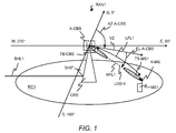
- FIG 1 shows schematically a block diagram of a radio access network RAN1 which contains a base station CBS and a mobile station MS1.
- GSM Global System for Mobile Communication
- GPRS General Packet Radio Service
- UMTS Universal Mobile Telecommunication Systems
- HSPA High Speed Packet Access
- LTE Long Term Evolution
- LTE-Advanced 3rd Generation Partnership Project
- base station may be considered synonymous to and/or referred to as a base transceiver station, cellular base station, access point base station, access point, macro base station, macrocell, micro base station, microcell, femtocell, picocell etc. and may describe equipment that provides wireless connectivity via one or more radio links to one or more mobile stations.
- macro base station may be considered synonymous to and/or referred to a base station, which provides a radio cell having a size in a range of several hundred meters up to several kilometres.
- a macro base station usually has a maximum output power of typically tens of watts.
- micro base station may be considered synonymous to and/or referred to a base station, which provides a radio cell having a size in a range of several tens of meters up to hundred meters.
- a micro base station usually has a maximum output power of typically several watts.
- Macro cell may be considered synonymous to and/or referred to a radio cell, which provides the widest range of all radio cell sizes. Macro cells are usually found in rural areas or along highways.
- micro cell may be considered synonymous to and/or referred to a radio cell in a cellular network served by a low power cellular base station, covering a limited area (smaller than an area of a macro cell) such as a mall, a hotel, or a transportation hub.
- a microcell is referred to a group of radio cells, which contain pico cells and femto cells.
- pico cell may be considered synonymous to and/or referred to a small cellular base station typically covering a small area, such as in-building (offices, shopping malls, train stations, stock exchanges, etc.), or more recently in-aircraft.
- pico cells are typically used to extend coverage to indoor areas where outdoor signals do not reach well, or to add network capacity in areas with very dense phone usage, such as train stations.
- femto cell may be considered synonymous to and/or referred to a small, low-power cellular base station, typically designed for use in a home or small business.
- a broader term which is more widespread in the industry is small cell, with femto cell as a subset.
- the term "mobile station” may be considered synonymous to, and may hereafter be occasionally referred to, as a mobile unit, mobile user, access terminal, user equipment, subscriber, user, remote station or a small cell, pico cell or femto cell when located in a moving vehicle such as a bus, a train or even a car.
- the mobile station may be for example a cellular telephone, a smart phone, a portable computer, a pocket computer, a hand-held computer, a personal digital assistant, a moving base station, a smart watch, a head mounted display such as a Google glass or a vehicle-mounted mobile device such as a repeater or relay.
- the base station CBS contains an antenna system A-CBS at a location of the base station CBS.
- the antenna system A-CBS contains a first highly directional antenna for a first wireless link HFL1 between the antenna system A-CBS and the mobile station MS1 for a wireless communication of first radio frequency signals in a first frequency range (see also Figure 3 ).
- the base station CBS determines based on a first location of the first highly directional antenna and further based on a second location of the second highly directional antenna first initial beam parameters for the first highly directional antenna such as a beam direction for applying an antenna pattern and for adjusting a direction of a radiation beam TB-CBS at the first highly directional antenna for the first wireless link HFL1.
- the base station CBS determines further based on a first orientation of the first highly directional antenna beamforming weights for the first highly directional antenna for applying the antenna pattern and for adjusting the direction of the radiation beam TB-CBS at the first highly directional antenna.
- the base station CBS further determines second initial beam parameters such as a beam direction for the second highly directional antenna of the mobile station MS1 based on the location of the first highly directional antenna and based on the location of the second highly directional antenna for applying an antenna pattern and adjusting a direction of a radiation beam TB-MS1 at the second highly directional antenna for the first wireless link HFL1.
- the base station CBS determines beamforming weights for the second highly directional antenna further based on the first orientation of the first highly directive antenna and further based on the second orientation of the second highly directional antenna for applying the antenna pattern and for adjusting the direction of the radiation beam TB-MS1 at the second highly directional antenna.
- the adjustment of the direction of the radiation beam TB-CBS may be for example according to an azimuth angle AZ-A-CBS and on an elevation angle EL-A-CBS.
- An origin of a two dimensional Cartesian coordinate system may be for example at the location of the antenna system A-CBS and a plane of the two-dimensional Cartesian coordinate system may be oriented in parallel to the Earth's surface.
- a first axis of the two-dimensional Cartesian coordinate system may be oriented towards the North pole (N), also known as the Geographic North Pole or Terrestrial North Pole, and towards the South pole (S), also known as the Geographic South Pole or Terrestrial South Pole.
- a second axis of the two-dimensional Cartesian coordinate system may be oriented towards the West cardinal direction (W) and the East cardinal direction (E).
- a line-of-sight direction from the antenna system A-CBS to the antenna system A-MS of the mobile station MS1 is given by a line-of-sight vector LOS-V.
- a projection of the line-of-sight vector LOS-V into the two-dimensional plane of the Cartesian coordinate system provides a further vector V2.
- the azimuth angle AZ-A-CBS may be given for example as an angle between the North direction and the further vector V2.
- the elevation angle EL-A-CBS may be given for example as an angle between the further vector V2 and the line-of-sight vector LOS-V.
- an azimuth angle and an elevation angle for the antenna system A-MS may be defined, which is not shown in Figure 1 for simplification but can be easily derived by a person skilled in the art.
- the first frequency range preferably contains frequencies equal to or above 10 GHz.
- the first frequency range may be for example a part of a so-called extremely high frequency range which is usually defined between 30 GHz and 300 GHz.
- the first frequency range may be adapted for generating radio frequency signals with millimetre wave frequencies between 20 GHz and 300 GHz.
- the antenna system A-CBS is further adapted for providing a second wireless link LFL1 between the antenna system A-CBS and the mobile station MS1 for a further wireless communication of second radio frequency signals in a second frequency range which contains preferably frequencies below 10 GHz.
- the second frequency range may be for example a frequency range as applied by a conventional cellular mobile communication system such as an UMTS or an LTE network or by a WLAN or a WiMAX network.
- the second frequency range may have for example radio frequencies around 5 GHz, around 3.5 GHz, around 2.4 GHz or around 700 MHz.
- the second wireless link LFL1 using the second frequency range is applied for signalling location information of the mobile station MS1 or for signalling second location information and second orientation information of the mobile station MS1 to the base station CBS, which uses the second location information or the second location information and the second orientation information for determining second initial beam parameters to be applied at the second highly directional antenna of the antenna system A-MS of the mobile station MS1 for adjusting a beam direction TB-MS1 for a wireless communication between the base station CBS and the mobile station MS1 via the first wireless link HFL1 in the first frequency range.
- the second wireless link LFL1 is further applied for signalling the second initial beam parameters for the second highly directional antenna from the base station CBS to the mobile station MS1.
- the base station CBS further contains an interface BHIF for a backhaul link BHL1 to either a further base station of the radio access network RAN1 or to a core network node of a cellular mobile communication system. More details of the base station CBS are described with respect to Figure 3 .
- the mobile station MS1 contains the antenna system A-MS.
- the antenna system A-MS contains the second highly directional antenna for the first wireless link HFL1 between the antenna system A-CBS and the mobile station MS1 for the wireless communication of the first radio frequency signals in the first frequency range (see also Figure 5 ).
- the antenna system A-MS is further adapted for providing the second wireless link LFL1 between the antenna system A-CBS and the mobile station MS1 for the further wireless communication of the second radio frequency signals in the second frequency range. More details of the mobile station MS1 are described with respect to Figure 5 .
- the first highly directional antenna may be adapted to form multiple beams in the first frequency range to multiple mobile stations.
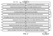
- Figure 2 shows a flow diagram of a method MET1-NN1 of the base station CBS for configuring radio frequency transmission between the first highly directional antenna connected to the base station CBS and the second highly directional antenna of the mobile station MS1.
- the beam parameters are designed only depending on the locations of the first and the second highly directional antenna and an external environment is not taken into account.
- the 2D scenario may be used when the first and the second highly directional antennas have a same z-coordinate (i.e. a same height). In such a case the elevation angle is simply zero for both, the first and the second highly directional antenna.
- the location of the first highly directional antenna of the base station CBS may be fixed (given by position data x cbs, 2 D, 1 , y cbs, 2 D, 1 ) for all locations of the second highly directional antenna of the mobile station MS1.
- the location of the second highly directional antenna is given for a first location (given by first position data x ms, 2 D, 1 , y ms, 2 D, 1 ) and a second location (given by second position data x ms, 2 D, 2 , y ms, 2 D, 2 ).
- beam direction parameters of the first highly directional antenna (azimuth angle Az cbs, 2 D, 1 for the first location and azimuth angle Az cbs, 2 D, 2 for the second location) and of the second highly directional antenna (azimuth angle Az ms, 2 D, 1 for the first location and azimuth angle Az ms, 2 D, 2 for the second location) are also different.
- the first highly directional antenna of the base station CBS may be tiltable but not movable. Therefore, the position data of the first highly directional antenna are the same for the various position data of the mobile station MS1 which contains the second highly directional antenna.
- table 1 Further parameters for further positions may be contained in table 1 for example in such a way, that for a grid with intervals of 10 m in x direction and 10 m in y direction for all possible positions of the mobile station MS1 within the radio cell RC1 beam direction values are pre-stored in the table 1.
- the x-values and y-values listed in the first and second column of the above table 1 are preferably positions in a two-dimensional Cartesian coordinate system, which is parallel to a section of the Earth's surface (see Figure 1 ).
- the above listed table 1 may be preferably applied, when the positions of the first highly directional antenna and of the second highly directional antenna are dominated by differences in the x-values and y-values and when differences in z-values (height values) of the first highly directional antenna and the second highly directional antenna are negligible for a calculation of the beam directions of the first highly directional antenna and the second highly directional antenna.
- the azimuth angles Az ms, 1 , Az ms, 2 for the beam direction of the beam TB-MS at the second highly directional antenna may be determined easily in a same way by a skilled person in the art based on a further equation similar to the equation (1).
- the azimuth angles Az cbs, 3 D, 1 , Az cbs, 3 D, 2 for the beam direction of the beam TB-CBS at the first highly directional antenna and for the azimuth angles Az ms, 3 D, 1 , Az ms, 3 D, 2 for the beam direction of the beam TB-MS at the second highly directional antenna may be determined for example by an equation, which corresponds to the equation (1).
- the elevation angles El ms, 3 D, 1 , El ms, 3 D, 2 for the beam direction of the beam TB-MS at the second highly directional antenna may be determined easily in a similar way by a skilled person in the art based on a further equation similar to the equation (2).
- the antenna type such as a uniform linear array, a rectangular planar array, a circular planar array or a cylindrical array has an influence on the beamforming weights to be used. This means that for different antenna types different beamforming weights may be stored in the database.
- the first row of table 3 contains beam direction parameters and beamforming parameters for a fixed location ( x cbs, 3 D, 1 , y cbs, 3 D, 1 , z cbs, 3 D, 1 ) of the first highly directional antenna, for a fixed type ( t cbs, 1 ) of the first highly directional antenna, for a first location ( x ms, 3 D, 1 , y ms, 3 D, 1 , z ms, 3 D, 1 ) of the second highly directional antenna and for a first type ( t ms, 1 ) of the second highly directional antenna (e.g.
- the fixed type of the first highly directional antenna may be for example a rectangular planar antenna array.
- the first type of the second highly directional antenna may be for example a uniform linear antenna array of a smartphone.
- the second row of table 3 contains in comparison to the first row beam direction parameters and beamforming parameters for a second type ( t ms, 2 ) of the second highly directional antenna such as a further rectangular planar antenna array (e.g. for a second mobile station of a second type different to the first type of the first mobile station) at same locations of the first and the second highly directional antenna.
- the third row of table 3 contains in comparison to the first row beam direction parameters and beamforming parameters for the first type ( t ms, 1 ) of the second highly directional antenna, for the fixed location of the first highly directional antenna and for a second location ( x ms, 3 D, 2 , y ms, 3 D, 2 , z ms, 3 D, 2 ) of the second highly directional antenna.
- the azimuth angles and the elevation angles may be given with respect to an orientation of an electrical boresight of the highly directional antennas.
- the electrical boresight may be for example equal to a perpendicular with respect to electrical excitation areas of an antenna array.
- the beamforming weigths for forming the beam TB-CBS at the first highly directional antenna with a direction relative to the boresight of the first highly directional antenna may be determined for a specific antenna type of the first highly directional antenna based on the beam direction and based on the orientation of the first highly directional antenna.
- a computation of the beamforming weights depend not only on the antenna type, but also on a criterion that shall be optimized. An example is given in the following:
- An antenna pattern and corresponding radiation beam for the first highly directional antenna may be designed by simply assuming that the maximum gain is in the direction of the mobile station MS.
- the beamforming weigths for forming the beam TB-MS1 at the second highly directional antenna with a direction relative to the boresight of the second highly directional antenna may be determined easily in a same way by a skilled person in the art based on a further equation similar to the equation (3).
- the database may be a local database and part of the base station CBS (see also Figure 3 ).
- the database may be a central database for a group of several base stations or for all base stations of a cellular mobile communication system.
- the base station CBS determines the location of the first highly directional antenna or determines the location and the orientation of the first highly directional antenna.
- the location of the first highly directional antenna may be for example pre-configured and stored in the local database of the base station CBS at a point of time, when the base station CBS is installed as part of the radio access network RAN1. In such a case, the base station CBS can easily retrieve the location of the first highly directional antenna by simply accessing the local database. Alternatively, the location may be measured by a position sensor near the first highly directional antenna.
- the location of the first highly directional antenna may be for example provided in a same format as the x values and the y values or as the x values, the y values and the z values, which are given above with respect to the tables 1, 2 and 3.
- the orientation of the first highly directional antenna may be represented for example by the electrical boresight and may be either pre-configured and stored in the local database of the base station CBS when the orientation of the first highly directional antenna is fixed or the location may be preferably measured by an orientation sensor near the first highly directional antenna, when the first highly directional antenna is tiltable in a mechanical way (more details about the position sensor and the orientation sensor are given with respect to the Figure 3 ).
- the orientation of the first highly directional antenna may be for example provided in a same format as the azimuth angles and the elevation angles, which are given above with respect to the tables 1, 2 and 3.
- the base station CBS receives from the mobile station MS1 via the second wireless link LFL1 second location information about the location of the mobile station MS1 (identical to the location of the second highly directional antenna) or receives from the mobile station MS1 via the second wireless link LFL1 the second location information and second orientation information (identical to the orientation of the second highly directional antenna) about the orientation of the mobile station MS1. If different antenna types are used at the mobile stations, the base station CBS preferably receives in addition to the second orientation information also second antenna type information about an antenna type of the second highly directional antenna of the mobile station MS1.
- the base station CBS may request from the mobile station MS1 the second location information or the second location information and the second orientation information and preferably the second antenna type information about the antenna type at a beginning of a wireless communication with the mobile station MS1 via the first wireless link HFL1.
- the mobile station MS1 may transmit the second location information or the second location information and the second orientation information and preferably the second antenna type information about the antenna to the base station CBS, when either the mobile station MS1 has been moved a predefined distance such as 10 m in comparison to a previous location for which the second location information has been transmitted or when the mobile station MS1 has been tilted a predefined angle such as 5° in comparison to a previous angle for which the second orientation information has been transmitted.
- the base station CBS accesses the database for retrieving the first initial beam parameters and the second initial beam parameters in correlation to current positions of the first highly directional antenna and the second highly directional antenna or in correlation to current positions of the first highly directional antenna and the second highly directional antenna and further in correlation to current orientations of the first highly directional antenna and the second highly directional antenna and preferably further in correlation to antenna types of the first highly directional antenna and the second highly directional antenna such as described with respect to tables 1, 2 or 3.
- the base station CBS determines the first initial beam parameters for the first highly directional antenna and the second initial beam parameters for the second highly directional antenna for example with an assumption that an LOS path is available between the first highly directional antenna and the second highly directional antenna.
- the base station CBS may for example determine beam directions to be applied at the first highly directional antenna and at the second highly directional antenna according to equations (1) and (2).
- the base station CBS may determine during the step S5 which may be executed after the step S4 beamforming weights to be applied at the first highly directional antenna and at the second highly directional antenna according to the equation (3) based on the pre-stored beam directions which may be retrieved for example from table 1 or table 2 and further based on current orientations of the first highly directional antenna and the second highly directional antenna.
- the base station CBS transmits to the mobile station MS1 via the second wireless link LFL2 the second initial beam parameters to be applied at the second highly directional antenna of the mobile station MS1.
- the second initial beam parameters may be for example either an azimuth angle or an azimuth angle and an elevation angle or beamforming weights to be applied by a transmitter of the mobile station MS1 for a transmission of uplink radio frequency signals from the second highly directional antenna.
- the base station CBS applies the first initial beam parameters for obtaining an initial antenna pattern and a corresponding beam direction of the radiation beam TB-CBS of the first highly directional antenna.
- a radio frequency signal to be transmitted is multiplied with a (usually) complex factor, a beamforming weight, which is dedicated for one of the antenna elements of the first highly directional antenna.
- This multiplication is repeated for each antenna element of the first highly directional antenna and can be done either by an analogue attenuator and phase shifter, or digitally on a digital baseband board before up-conversion.
- a determination of this complex beamforming weight is according to equation (3) provided above.
- the base station CBS determines first optimized beam parameters for the radiation beam TB-CBS of the first highly directional antenna.
- the determination of the first optimized beam parameters may be obtained for example in a following way: Differently pre-coded pilot signals, which represent different beam directions in the vicinity of the initial beam direction may be transmitted in downlink direction during a training phase from the base station CBS to the mobile station MS1.
- the mobile station MS1 may measure receive powers of the differently pre-coded pilot signals and may report corresponding receive power values to the base station CBS via the first wireless link HFL1 or the second wireless link LFL1.
- the base station CBS may select and determine new beamforming weights as first optimized beam parameters for the radiation beam of the first highly directional antenna for that pre-coding for which a maximum receive power has been reported. This method may be similar to a method as defined as a special operation mode in 3GPP Release 10.
- the base station CBS preferably applies the first optimized beam parameters for obtaining an optimized beam direction of the radiation beam TB-CBS of the first highly directional antenna preferably by applying directly the beamforming weights as selected in the previous step S8.
- the base station CBS receives from the mobile station MS1 via the second wireless link LFL1 or via the first wireless link HFL1 second optimized beam parameters as applied at the second highly directional antenna for obtaining an optimized beam direction of the radiation beam TB-MS.
- the second optimized beam parameters preferably contain beamforming weights as applied for the optimized beam direction of the radiation beam TB-MS.
- the base station CBS stores to the database the first optimized beam parameters, when determined by the step S8 or stores to the database the second optimized beam parameters, when received by the step S10 in correlation to current locations of the first highly directional antenna of the base station CBS and of the second highly directional antenna of the mobile station MS1 or in correlation to current locations of the first highly directional antenna and of the second highly directional antenna and further in correlation to current orientations of the first highly directional antenna and of the second highly directional antenna.
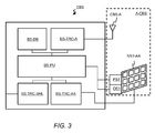
- FIG. 3 shows schematically an exemplarily block diagram of the base station CBS.
- the base station CBS contains a local database BS-DB.
- the database BS-DB may be not a local database and may be not part of the base station CBS but may be instead a central database of a central network node of the radio access network RAN1 or of a core network of a cellular mobile communication system.
- the base station CBS further contains a first transceiver BS-TRC-AA for transmitting downlink radio frequency signals in the first frequency range via the first highly directional antenna NN1-AA and for receiving uplink radio frequency signals in the first frequency range via the first highly directional antenna NN1-AA, a second transceiver BS-TRC-A for transmitting downlink radio frequency signals in the second frequency range via a further antenna CBS-A and for receiving uplink radio frequency signals in the second frequency range via the further antenna CBS-A and a third transceiver BS-TRC-BHL for transmitting and receiving user data or signaling information via the backhaul link BHL1 from a neighboring base station or from a core network of a cellular mobile communication system.
- a first transceiver BS-TRC-AA for transmitting downlink radio frequency signals in the first frequency range via the first highly directional antenna NN1-AA and for receiving uplink radio frequency signals in the first frequency range via the first highly directional antenna NN1-AA
- the base station further contains a processing module or processing unit BS-PU which is internally connected to the database BS-DB, the first transceiver BS-TRC-AA, the second transceiver BS-TRC-A and the third transceiver BS-TRC-BHL and which operates and controls the database BS-DB, the first transceiver BS-TRC-AA, the second transceiver BS-TRC-A and the third transceiver BS-TRC-BHL.
- the processing unit BS-PU is further adapted for determining the first initial beam parameters, the second initial beam parameters and the first optimized beam parameters.
- the base station CBS may further contain the antenna system A-CBS when co-located to the base station CBS or the antenna system A-CBS may be regarded as a separate unit when remotely connected to the base station CBS.
- the antenna system A-CBS contains the first highly directional antenna NN1-AA, the further antenna CBS-A, a position sensor PS1 near or attached to the first highly directional antenna NN1-AA and connected to the processing unit BS-PU of the base station CBS and an orientation sensor OS1 attached to the first highly directional antenna NN1-AA which is also connected to the processing unit BS-PU of the base station CBS.
- the first highly directional antenna NN1-AA may be for example a rectangular planar antenna array which contains 36 antenna elements in a 6 x 6 arrangement.
- An antenna array with such a large number of antenna elements may be also called a massive MIMO antenna array, although MIMO antenna arrays in general do not fulfil the constraints needed for forming narrow antenna pattern without grating lobes, as needed for the purpose of the described embodiments.
- the rectangular planar antenna array may contain for example 25 antenna elements in a 5 x 5 arrangement, 40 antenna elements in a 8 x 5 arrangement (8 columns and 5 rows), 50 antenna elements in a 5 x 10 arrangement (5 columns and 10 rows) or 64 antenna elements in a 8 x 8 arrangement.
- rectangular planar antenna arrays with further number of antenna elements in further arrangements of columns and rows may be used for the first highly directional antenna NN1-AA.
- the further antenna CBS-A may be an antenna with a single antenna element or also a MIMO antenna array with for example 4 antenna elements in a 2 x 2 arrangement.
- GLONASS Globalnaya navigatsionnaya sputnikovaya
- Galileo global navigation satellite system currently being built by the European Union (EU) and European Space Agency (ESA)
- IRNSS autonomous regional satellite navigation system being developed by the Indian Space Research Organisation (ISRO)
- Beidou-2 a Chinese satellite navigation system.
- the position sensor PS1 may be adapted to provide absolute location data in a form of x-values, y-values and preferably also z
- the orientation sensor OS1 may be for example an absolute orientation sensor for measuring angular rate, acceleration and geomagnetic fields preferably in three perpendicular axes.
- the orientation sensor OS1 may be adapted to provide absolute orientation data in a form of azimuth angles and elevation angles to the processing unit BS-PU.
- the orientation sensor OS1 may provide relative data for an amount of a change of the azimuth angle and an amount of a change of the elevation angle to the processing unit BS-PU and the processing unit BS-PU which may be has stored previous absolute values of the azimuth angle and the elevation angle is adapted to calculate a new azimuth angle and a new elevation angle based on the stored previous absolute values and the newly received relative data.
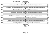
- Figure 4 shows a flow diagram of a method MET1-NN2 of the mobile station MS1 for configuring the radio frequency transmission between the first highly directional antenna NN1-AA connected to the base station CBS and the second highly directional antenna of the mobile station MS1.
- the mobile station MS1 determines a location of the mobile station MS1 and an orientation of the mobile station MS1. Because of the co-location of the mobile station MS1 and the second highly directional antenna preferably in a same housing a location and orientation of the mobile station MS1 is the same as a location and an orientation of the second highly directional antenna.
- the location of the mobile station MS1 may be for example measured by a position sensor as part of the mobile station MS1.
- the location of the mobile station MS1 may be for example provided in a same format as the x values and the y values or as the x values, the y values and the z values, which are given above with respect to the tables 1, 2 and 3.
- the orientation of the second highly directional antenna may be represented for example also by the electrical boresight and may be preferably measured by an orientation sensor as part of the mobile station MS1.
- the orientation of the second highly directional antenna may be for example provided in a same format as the azimuth angles and the elevation angles, which are given above with respect to the tables 1, 2 and 3.
- the mobile station MS1 transmits the second location information to the base station CBS via the second wireless link LFL1 using the second frequency range.
- the second wireless link LFL1 may be for example a cellular band of a radio access technology such as UMTS or LTE.
- the second wireless link LFL1 may be based on one of the radio access technologies which are described with respect to the radio access network RAN1 which is shown in Figure 1 .
- the second location information may contain for example an x value and a y value of the current location of the mobile station MS1 or the x value, the y values and a z value of the current location.
- the mobile station MS1 transmits the second location information and the second orientation information and preferably the second antenna type information about the antenna type of the second highly directional antenna to the base station CBS via the second wireless link LFL1 using the second frequency range.
- the second orientation information contains an azimuth value and an elevation value of the current orientation of the mobile station MS1.
- the second antenna type information may contain an identifier for the antenna type being used for the second highly directional antenna at the mobile station MS1.
- the mobile station MS1 receives the second initial beam parameters from the base station CBS via the second wireless link LFL1.
- the mobile station MS1 determines beamforming weights for the uplink transmission from the second highly directional antenna as the second initial beam parameters based on an equation similar to the equation (3).
- the mobile station MS1 applies the second initial beam parameters such as beamforming weights determined by the step M4 or received by the step M3 for obtaining a corresponding antenna pattern at the second highly directional antenna for the uplink transmission from the second highly directional antenna.
- the mobile station MS1 determines second optimized beam parameters for the radiation beam TB-MS1 of the second highly directional antenna.
- the determination of the second optimized beam parameters may be obtained for example in a following way:
- Further differently pre-coded pilot signals, which represent different beam directions in the vicinity of the initial beam direction of the second highly directional antenna may be transmitted in uplink direction during a training phase from the mobile station MS1 to the base station CBS.
- the base station CBS may measure receive powers of the further differently pre-coded pilot signals and may report corresponding receive power values to the mobile station MS1 via the first wireless link HFL1 or the second wireless link LFL1.
- the mobile station MS1 may select and determine new beamforming weights as second optimized beam parameters for the radiation beam of the second highly directional antenna for that pre-coding for which a maximum receive power has been reported from the base station CBS.
- This method may be similar or equal to the method as described with respect to the step S8 of the method MET1-NN1 which is executed by the base station CBS.
- the mobile station MS1 preferably applies the second optimized beam parameters for obtaining an optimized beam direction of the radiation beam TB-MS1 of the second highly directional antenna preferably by applying directly the beamforming weights as selected in the previous step M6.
- the mobile station MS1 transmits information of the second optimized beam parameters to the base station CBS via the first wireless link HFL1 or the second wireless link LFL1 so that the base station CBS is able to store the second optimized beam parameters in the database BS-DB.
- the procedure for determining, applying and transmitting information of the second optimized beam parameters may be repeated, when required.
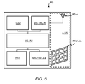
- FIG 5 shows schematically an exemplarily block diagram of the mobile station MS.
- the mobile station MS may be the mobile station MS1 as shown in Figure 1 or the mobile station MS2 as shown in Figures 6a and 6b .
- the mobile station MS contains a first transceiver MS-TRC-AA for transmitting the uplink radio frequency signals in the first frequency range via the second highly directional antenna NN2-AA and for receiving the downlink radio frequency signals in the first frequency range via the second highly directional antenna NN2-AA, a second transceiver MS-TRC-A for transmitting the uplink radio frequency signals in the second frequency range via a further antenna MS-A and for receiving the downlink radio frequency signals in the second frequency range via the further antenna MS-A and a processing module or processing unit MS-PU which is internally connected to the first transceiver unit MS-TRC-AA and the second transceiver unit MS-TRC-A and which controls the first transceiver unit MS-TRC-AA and the second transceiver unit MS-TRC-A.
- the mobile station MS further contains the antenna system A-MS.
- the antenna system A-MS contains the second highly directional antenna NN2-AA and the further antenna MS-A.
- the second highly directional antenna NN2-AA may be for example a rectangular planar antenna array which contains 36 antenna elements in a 6 x 6 arrangement.
- the rectangular planar antenna array may contain for example 25 antenna elements in a 5 x 5 arrangement, 40 antenna elements in a 8 x 5 arrangement (8 columns and 5 rows), 50 antenna elements in a 5 x 10 arrangement (5 columns and 10 rows) or 64 antenna elements in a 8 x 8 arrangement.
- antenna arrays with further number of antenna elements in further arrangements of columns and rows may be used for the second highly directional antenna NN2-AA.
- the further antenna MS-A may be an antenna with a single antenna element or also a MIMO antenna array with for example 2 antenna elements in a 2 x 1 or 1 x 2 arrangement.
- the mobile station MS further contains a position sensor PS2 which is connected to the processing unit MS-PU and which may be of a same type as the position sensor PS1 of the antenna system A-CBS.
- the mobile station MS even further contains an orientation sensor OS2 which is also connected to the processing unit MS-PU and which may be of a same type as the orientation sensor OS1 of the antenna system A-CBS.
- the sensors PS2 and OS2 may be of different type in comparison to the sensors PS1 and OS1 and may be miniaturized sensors which are adapted for being installed in a small size housing of the mobile station MS.
- Figure 6a shows schematically a block diagram of a cellular radio access network RAN2 which contains a base station CBS1 for radio frequency transmission in the second frequency range within a radio cell RC2, a first base station MMWBS1 adapted for radio frequency transmission in the first frequency range within a radio cell RC3 and a second base station MMWBS2 adapted for radio frequency transmission in the first frequency range within a radio cell RC4.
- the cellular radio access network RAN2 may be based on one of the radio access technologies which are described with respect to the radio access network RAN1 which is shown in Figure 1 .
- the base station CBS1 is connected via a fixed or wireless backhaul link BHL2 to a further base station or to a network node of a core network of a cellular mobile communication system and contains a co-located or remotely connected antenna system A-CBS1, which is adapted for a wireless communication via a second wireless link LFL2 in the second frequency range and which may be further adapted for a wireless communication with the first base station MMWBS1 via a fixed or wireless backhaul link BHL3 and the second base station MMWBS2 via a fixed or wireless backhaul link BHL4 for exchanging user data and signaling information.
- the wireless backhaul links BHL3, BHL4 may apply radio frequency transmission based on a radio access technology such as UMTS or LTE.
- the fixed backhaul links BHL3, BHL4 may apply a transmission technology such as wireline transmission (e.g. fiber transmission, coax or DSL-like transmission) or wireless point to point transmission.
- the first base station MMWBS1 and the second base station MMWBS2 may be slave base stations and may be controlled by the base station CBS1 as a master base station. This means that the base station CBS1 may for example decide about a usage of radio resources within the radio cell RC3 and the radio cell RC4 or may decide which mobile stations shall be served by which one of the base stations MMWBS1, MMWBS2.
- the cellular radio access network RAN2 further contains a mobile station MS2 within a coverage area of radio cell RC3.
- the mobile station MS2 contains the antenna system A-MS as described above with respect to Figure 5 .
- This means that the mobile station MS2 is adapted to exchange user data and signaling with the first base station MMWBS1 via a first wireless link HFL2 which applies radio frequency signals in the first frequency range and to exchange signaling data with the base station CBS1 via a second wireless link LFL2 which applies radio frequency signals in the second frequency range.
- the first base station MMWBS1 contains an antenna system A-MMWBS1 which is a highly directional antenna for the first frequency range.
- the second base station MMWBS2 contains an antenna system A-MMWBS2 which is also a highly directional antenna. Further information with respect to the first base station MMWBS1 and the second base station MMWBS1 is given with respect to Figure 9 .
- the base station CBS1 determines the first initial beam parameters for the antenna system A-MMWBS1 and second initial beam parameters for the mobile station MS2 based on a location and an orientation of the antenna system A-MMWBS1 and based on a location and an orientation of the mobile station MS2 for adjusting a direction of a radiation beam TB1-MMWBS1 at the antenna system A-MMWBS1 and a direction of a radiation beam TB1-MS at the mobile station MS2 for the first wireless link HFL2.
- the base station CBS1 determines the first initial parameters for the antenna system A-MMWBS2 and the second initial beam parameters for a mobile station served by the second base station MMWBS2.
- the second wireless link LFL2 using the second frequency range is applied for signalling the second location information of the mobile station MS1 or for signalling the second location information and the second orientation information of the mobile station MS1 to the base station CBS1, which uses the second location information or the second location information and the second orientation information and the first location information for determining the second initial beam parameters to be applied at the antenna system A-MS of the mobile station MS2 for adjusting the radiation beam TB1-MS for a wireless communication between the first base station MMWBS1 and the mobile station MS2 via the first wireless link HFL2 in the first frequency range.
- the second wireless link LFL2 is further applied for signalling the second initial beam parameters to be applied at the antenna system A-MS from the base station CBS1 to the mobile station MS2.
- the first initial beam parameters and the second initial beam parameters may be determined or may be retrieved from a local or central database for an assumption of an LOS transmission path between the antenna system A-MMWBS1 and the mobile station MS2. It may happen relatively often that an obstacle OBST such as a house, a lorry, a hill etc. may be located between the first base station MMWBS1 and the mobile station MS2 and the obstacle OBST may disturb the LOS transmission path to a large extend or may even prevent the LOS transmission path. In such a case an alternative transmission path ATP may determined as shown with respect to Figure 6b .
- an obstacle OBST such as a house, a lorry, a hill etc.
- a procedure for determining the alternative transmission path for the first wireless link HFL2 may be similar to the steps S8/S9 of the method MET1-NN1 (see Figure 2 ) for the first base station MMWBS1 and to the steps M6/M7 of the method MET1-NN2 (see Figure 4 ) for the mobile station MS2.
- pilot signals which represent different beam directions in the vicinity of the initial beam direction of the first highly directional antenna or the second highly directional antenna during a training phase some of the pilot signals may be reflected by an object such as a building, a hill, a mountain etc.
- first base station MMWBS1 or mobile station MS2 may select and determine new beamforming weights as optimized beam parameters for a new radiation beam TB2-MMWBS1 at the first highly directional antenna of the first base station MMWBS1 and for a new radiation beam TB2-MS at the second highly directional antenna of the mobile station MS2.
- the new beamforming weigths or the new beam directions may be reported as first optimized beam parameters and second optimized beam parameters from the first base station MMWBS1 and the mobile station MS2 to the base station CBS1 for storing in the local or central database for later usage.
- Figure 7 shows a flow diagram of a method MET2-NN1 of the base station CBS1 for configuring radio frequency transmission between the first highly directional antenna connected to the first base station MMWBS1 and the second highly directional antenna of the mobile station MS2.
- the elements in Figure 7 that correspond to elements of Figure 2 have been designated by same reference numerals and in general are not described again for simplification.
- the base station CBS1 controls one or several of the base stations MMWBS1, MMWBS2.
- the base station CBS1 may for example decide about a usage of radio resources within the radio cell RC3 and the radio cell RC4 or may decide which mobile stations shall be served by which one of the base stations MMWBS1, MMWBS2.
- the base station CBS1 may select for example based on a request received from the mobile station MS2 by a radio frequency transmission in the second frequency range one of the base stations MMWBS1, MMWBS2 for serving the mobile station MS2 with user data by applying radio frequency signals in the first frequency range.
- the selection may depend for example on location information received from the mobile station MS2 via the second wireless link LFL2 or on a determination of distances between the mobile station MS2 and the base stations MMWBS1, MMWBS2 based on location information of the base stations MMWBS1, MMWBS2 and the mobile station MS2.
- step S2a as an alternative to the step S2 (the first location information, the first orientation information and preferably the first antenna type information of the first highly directional antenna of the base station MMWBS1 is stored at the local database of the base station CBS2 and may be retrieved by the step S3 from the local database), the base station CBS1 receives from the selected base station MMWBS1 via the backhaul link BHL3 the first location information about the location of the first highly directional antenna or receives from the base station CBS1 via the backhaul link BHL3 the first location information and the first orientation information about the orientation of the first highly directional antenna of the first base station MMWBS1.
- the first antenna type information of the first highly directional antenna may be received by the base station CBS1.
- the base station CBS1 may request for example from the base station MMWBS1 the first location information or the first location information and the first orientation information and preferably the first antenna type information at a beginning of a wireless communication between the first base station MMWBS1 and the mobile station MS2 via the first wireless link HFL2.
- the base station CBS1 transmits the first initial beam parameters being determined by the step S5 to the first base station MMWBS1 for being applied at the first highly directional antenna of the first base station MMWBS1.
- the base station CBS1 receives from the base station MMWBS1 via the backhaul link BHL3 the first optimized beam parameters such as optimized beamforming weights as being applied at the first highly directional antenna of the base station MMWBS1 for obtaining an optimized beam direction of the radiation beam TB2-MMWBS1, e.g. for the case as described above, when the LOS transmission path is not available or not suitable for achieving a sufficient high data rate.
- the first optimized beam parameters such as optimized beamforming weights as being applied at the first highly directional antenna of the base station MMWBS1 for obtaining an optimized beam direction of the radiation beam TB2-MMWBS1, e.g. for the case as described above, when the LOS transmission path is not available or not suitable for achieving a sufficient high data rate.
- Figure 8 shows schematically an exemplarily block diagram of the base station CBS1.
- the elements in Figure 8 that correspond to elements of Figure 3 have been designated by same reference numerals and in general are not described again for simplification.
- the base station CBS1 contains the local database BS-DB, the second transceiver BS-TRC-A and the third transceiver BS-TRC-BHL.
- the base station CBS1 further contains a first transceiver BS-TRC-A2 for enabling the backhaul links BHL3, BHL4.
- the backhaul links BHL3, BHL4 may be wireless backhaul links, which are served by an antenna CBS1-A2 which is connected to the first transceiver BS-TRC-A2.
- the base station CBS1 further contains a processing module or processing unit CBS1-PU which is internally connected to the database BS-DB, the first transceiver BS-TRC-A2, the second transceiver BS-TRC-A and the third transceiver BS-TRC-BHL and which operates and controls the database BS-DB, the first transceiver BS-TRC-A2, the second transceiver BS-TRC-A and the third transceiver BS-TRC-BHL.
- the processing unit CBS1-PU is further adapted for determining the first initial beam parameters and the second initial beam parameters.
- the base station CBS1 may further contain the antenna system A-CBS1 when co-located to the base station CBS1 or the antenna system A-CBS1 may be regarded as a separate unit when remotely connected to the base station CBS1.
- the antenna system A-CBS1 contains the antenna CBS-A and the antenna CBS1-A2.
- the antenna CBS1-A2 may contain a single antenna element or may be a MIMO antenna with two, four or more antenna elements. Embodiments for the antenna CBS-A have been already explained above with respect to Figure 3 .
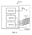
- Figure 9 shows schematically an exemplarily block diagram of a base station MMWBS which may be for example the first base station MMWBS1 or the second base station MMWBS2 as shown in Figures 6a and 6b .
- the elements in Figure 9 that correspond to elements of Figure 3 have been designated by same reference numerals and in general are not described again for simplification.
- the base station MMWBS contains the first transceiver BS-TRC-AA and a second transceiver BS-TRC-ANT which is connected to an antenna ANT for enabling the wireless backhaul links BHL3, BHL4 to the base station CBS1.
- the base station MMWBS further contains a processing module or processing unit MMWBS-PU which is internally connected to the first transceiver BS-TRC-AA and the second transceiver BS-TRC-ANT and which operates and controls the first transceiver BS-TRC-AA and the second transceiver BS-TRC-ANT.
- the processing unit MMWBS-PU may be adapted for determining the first optimized beam parameters and for applying the first initial beam parameters and the first optimized beam parameters at the first highly directional antenna NN1-AA.
- the base station MMWBS may further contain the antenna system A-MMWBS when the antenna system A-MMWBS is co-located to the base station MMWBS or the antenna system A-MMWBS may be regarded as a separate unit when remotely connected to the base station MMWBS.
- the antenna system A-MMWBS may be the antenna system A-MMWBS1 of the first base station MMWBS1 or the antenna system A-MMWBS2 of the second base station MMWBS2 and contains the first highly directional antenna NN1-AA, the antenna ANT, the position sensor PS1 near or attached to the first highly directional antenna NN1-AA and connected to the processing unit MMWBS-PU and the orientation sensor OS1 which is also connected to the processing unit MMWBS-PU.
- Figure 10 shows schematically a block diagram of a cellular radio access network RAN3 which contains a base station CBS2 for radio frequency transmission in the second frequency range within a radio cell RC5 and a further base station CBS3 also for radio frequency transmission in the second frequency range within a radio cell RC6.
- the cellular radio access network RNA3 may be based on one of the radio access technologies which are described with respect to the radio access network RAN1 which is shown in Figure 1 .
- the base station CBS2 is connected via a fixed or wireless backhaul link BHL6 to a further base station or to a network node of a core network of a cellular mobile communication system and contains a co-located or remotely connected antenna system A-CBS2, which is adapted for a wireless communication via a wireless backhaul link BHL5 in the first frequency range with the further base station CBS3 and which is further adapted for a wireless communication in the second frequency range with mobile stations which are located within a radio cell RC5 of the base station CBS2.
- the further base station CBS3 contains a co-located or remotely connected antenna system A-CBS3, which is adapted for a wireless communication via the wireless backhaul link BHL5 in the first frequency range with the base station CBS2 and which is further adapted for a wireless communication in the second frequency range with mobile stations which are located within a radio cell RC6 of the further base station CBS3.
- the antenna system A-CBS2 may contain the first highly directional antenna and the base station CBS2 may operate according to the method MET1-NN1 which is described with respect to Figure 2 . Thereby, a radiation beam TB-CBS2 of the antenna system A-CBS2 for the backhaul link BHL5 is initialed or optimized.
- the antenna system A-CBS3 may contain the second highly directional antenna and the further base station CBS3 may operate according to the method MET1-NN2 which is described with respect to Figure 4 . Thereby, a radiation beam TB-CBS3 of the antenna system A-CBS3 for the backhaul link BHL5 is initiated or optimized.
- the first highly directional antenna of the base station CBS2 may be adapted to form multiple beams for multiple wireless backhaul links in the first frequency range to multiple second highly directional antennas of multiple further base stations.
- Functional blocks denoted as "means for performing a certain function” shall be understood as functional blocks comprising circuitry that is adapted for performing the certain function, respectively. Hence, a “means for something” may as well be understood as a “means being adapted or suited for something”. A means being adapted for performing a certain function does, hence, not imply that such means necessarily is performing said function (at a given time instant).
- processors may be provided through the use of dedicated hardware, as e.g. a processor, as well as hardware capable of executing software in association with appropriate software.
- the functions may be provided by a single dedicated processor, by a single shared processor, or by a plurality of individual processors, some of which may be shared.
- explicit use of the term "processor” or “controller” should not be construed to refer exclusively to hardware capable of executing software, and may implicitly include, without limitation, DSP hardware, network processor, ASIC, FPGA, read only memory (ROM) for storing software, random access memory (RAM), and non-volatile storage.
- Other hardware conventional and/or custom, may also be included.
- any block diagrams herein represent conceptual views of illustrative circuitry embodying the principles of the invention.
- any flow charts, flow diagrams, state transition diagrams, pseudo code, and the like represent various processes which may be substantially represented in computer readable medium and so executed by a computer or processor, whether or not such computer or processor is explicitly shown.
- each claim may stand on its own as a separate embodiment. While each claim may stand on its own as a separate embodiment, it is to be noted that - although a dependent claim may refer in the claims to a specific combination with one or more other claims - other embodiments may also include a combination of the dependent claim with the subject matter of each other dependent claim. Such combinations are proposed herein unless it is stated that a specific combination is not intended. Furthermore, it is intended to include also features of a claim to any other independent claim even if this claim is not directly made dependent to the independent claim.
- a computer program product may contain computer-executable instructions for performing the methods MET1-NN1, MET2-NN1, MET1-NN2, when the computer program product is executed on a programmable hardware device such as a DSP, an ASIC or an FPGA.
- a digital data storage device may encode a machine-executable program of instructions to perform one of the methods MET1-NN1, MET2-NN1, MET1-NN2.
- a single step may include or may be broken into multiple sub steps. Such sub steps may be included and part of the disclosure of this single step unless explicitly excluded.
Priority Applications (1)
| Application Number | Priority Date | Filing Date | Title |
|---|---|---|---|
| EP14305078.9A EP2897304A1 (fr) | 2014-01-21 | 2014-01-21 | Procédés d'un premier et un second noeud de réseau d'accès radio permettant de configurer une transmission de fréquence radio à micro-ondes entre une première antenne et une seconde antenne hautement directionnelles, lesdits premier et second noeuds de réseau d'accès radio |
Applications Claiming Priority (1)
| Application Number | Priority Date | Filing Date | Title |
|---|---|---|---|
| EP14305078.9A EP2897304A1 (fr) | 2014-01-21 | 2014-01-21 | Procédés d'un premier et un second noeud de réseau d'accès radio permettant de configurer une transmission de fréquence radio à micro-ondes entre une première antenne et une seconde antenne hautement directionnelles, lesdits premier et second noeuds de réseau d'accès radio |
Publications (1)
| Publication Number | Publication Date |
|---|---|
| EP2897304A1 true EP2897304A1 (fr) | 2015-07-22 |
Family
ID=50156692
Family Applications (1)
| Application Number | Title | Priority Date | Filing Date |
|---|---|---|---|
| EP14305078.9A Withdrawn EP2897304A1 (fr) | 2014-01-21 | 2014-01-21 | Procédés d'un premier et un second noeud de réseau d'accès radio permettant de configurer une transmission de fréquence radio à micro-ondes entre une première antenne et une seconde antenne hautement directionnelles, lesdits premier et second noeuds de réseau d'accès radio |
Country Status (1)
| Country | Link |
|---|---|
| EP (1) | EP2897304A1 (fr) |
Cited By (8)
| Publication number | Priority date | Publication date | Assignee | Title |
|---|---|---|---|---|
| WO2017067591A1 (fr) * | 2015-10-21 | 2017-04-27 | Huawei Technologies Co., Ltd. | Appareil de communication et procédé pour faire fonctionner un appareil de communication |
| US9871570B1 (en) | 2016-12-13 | 2018-01-16 | Nxp Usa, Inc. | Beam determining unit and beam-searching method for a wireless heterogeneous network |
| WO2018013026A1 (fr) * | 2016-07-15 | 2018-01-18 | Telefonaktiebolaget Lm Ericsson (Publ) | Premier dispositif de communication et procédés permettant de lancer une transmission sur la base d'un ensemble de correspondances obtenu |
| WO2018085556A3 (fr) * | 2016-11-02 | 2018-07-05 | Qualcomm Incorporated | Amélioration de signal de référence d'affinement de faisceau pour un support de mobilité supérieure |
| CN109075824A (zh) * | 2016-08-03 | 2018-12-21 | 索尼公司 | 无线通信系统中的电子设备和服务器以及无线通信方法 |
| WO2019120492A1 (fr) * | 2017-12-19 | 2019-06-27 | Telefonaktiebolaget Lm Ericsson (Publ) | Établissement amélioré de communication entre des nœuds dans un système de communication |
| CN109997320A (zh) * | 2016-11-25 | 2019-07-09 | 三星电子株式会社 | 包括天线的设备及其控制方法 |
| EP3278467B1 (fr) * | 2015-08-14 | 2020-01-01 | Huawei Technologies Co., Ltd. | Noeud d'accès, noeud utilisateur, et procédé de détermination d'au moins un paramètre de synthèse de faisceau |
Citations (5)
| Publication number | Priority date | Publication date | Assignee | Title |
|---|---|---|---|---|
| US20100215027A1 (en) * | 2009-02-24 | 2010-08-26 | Yong Liu | Techniques for Flexible and Efficient Beamforming |
| US20120014367A1 (en) * | 2010-07-15 | 2012-01-19 | Canon Kabushiki Kaisha | Methods and devices for transmitting and receiving data signals in a wireless network over a plurality of transmission paths |
| EP2498414A1 (fr) * | 2009-11-04 | 2012-09-12 | Nec Corporation | Procédé de commande pour système de communication sans fil, système de communication sans fil et dispositif de communication sans fil |
| WO2012158045A2 (fr) * | 2011-05-16 | 2012-11-22 | Radionor Communications As | Procédé et système destinés à un système de communication mobile ad hoc de formation de faisceaux, adaptatif, de longue portée |
| US20130072244A1 (en) * | 2011-09-15 | 2013-03-21 | Samsung Electronics Co. Ltd. | Apparatus and method for beam selecting in beamformed wireless communication system |
-
2014
- 2014-01-21 EP EP14305078.9A patent/EP2897304A1/fr not_active Withdrawn
Patent Citations (5)
| Publication number | Priority date | Publication date | Assignee | Title |
|---|---|---|---|---|
| US20100215027A1 (en) * | 2009-02-24 | 2010-08-26 | Yong Liu | Techniques for Flexible and Efficient Beamforming |
| EP2498414A1 (fr) * | 2009-11-04 | 2012-09-12 | Nec Corporation | Procédé de commande pour système de communication sans fil, système de communication sans fil et dispositif de communication sans fil |
| US20120014367A1 (en) * | 2010-07-15 | 2012-01-19 | Canon Kabushiki Kaisha | Methods and devices for transmitting and receiving data signals in a wireless network over a plurality of transmission paths |
| WO2012158045A2 (fr) * | 2011-05-16 | 2012-11-22 | Radionor Communications As | Procédé et système destinés à un système de communication mobile ad hoc de formation de faisceaux, adaptatif, de longue portée |
| US20130072244A1 (en) * | 2011-09-15 | 2013-03-21 | Samsung Electronics Co. Ltd. | Apparatus and method for beam selecting in beamformed wireless communication system |
Cited By (18)
| Publication number | Priority date | Publication date | Assignee | Title |
|---|---|---|---|---|
| EP3278467B1 (fr) * | 2015-08-14 | 2020-01-01 | Huawei Technologies Co., Ltd. | Noeud d'accès, noeud utilisateur, et procédé de détermination d'au moins un paramètre de synthèse de faisceau |
| US10554277B2 (en) | 2015-08-14 | 2020-02-04 | Huawei Technologies Co., Ltd. | Access node, user node and method for determining at least one beamforming parameter |
| CN108141266A (zh) * | 2015-10-21 | 2018-06-08 | 华为技术有限公司 | 通信装置和操作通信装置的方法 |
| WO2017067591A1 (fr) * | 2015-10-21 | 2017-04-27 | Huawei Technologies Co., Ltd. | Appareil de communication et procédé pour faire fonctionner un appareil de communication |
| CN108141266B (zh) * | 2015-10-21 | 2020-12-08 | 华为技术有限公司 | 通信装置和操作通信装置的方法 |
| US11283499B2 (en) | 2016-07-15 | 2022-03-22 | Telefonaktiebolaget Lm Ericsson (Publ) | First communication device and methods thereby for initiating transmission based on an obtained set of correspondences |
| WO2018013026A1 (fr) * | 2016-07-15 | 2018-01-18 | Telefonaktiebolaget Lm Ericsson (Publ) | Premier dispositif de communication et procédés permettant de lancer une transmission sur la base d'un ensemble de correspondances obtenu |
| CN109075824A (zh) * | 2016-08-03 | 2018-12-21 | 索尼公司 | 无线通信系统中的电子设备和服务器以及无线通信方法 |
| EP3468054A4 (fr) * | 2016-08-03 | 2019-05-15 | Sony Corporation | Appareil électronique et serveur de système de communication sans fil, et procédé de communication sans fil |
| US10506629B2 (en) | 2016-11-02 | 2019-12-10 | Qualcomm Incorporated | Beam refinement reference signal enhancement for higher mobility support |
| WO2018085556A3 (fr) * | 2016-11-02 | 2018-07-05 | Qualcomm Incorporated | Amélioration de signal de référence d'affinement de faisceau pour un support de mobilité supérieure |
| US11051179B2 (en) | 2016-11-25 | 2021-06-29 | Samsung Electronics Co., Ltd. | Device including antenna and control method thereof |
| CN109997320A (zh) * | 2016-11-25 | 2019-07-09 | 三星电子株式会社 | 包括天线的设备及其控制方法 |
| EP3510708A4 (fr) * | 2016-11-25 | 2019-11-13 | Samsung Electronics Co., Ltd. | Dispositif comprenant une antenne et procédé de commande associé |
| EP3337052A1 (fr) * | 2016-12-13 | 2018-06-20 | NXP USA, Inc. | Unité de détermination de faisceau et procédé de recherche de faisceau pour un réseau hétérogène sans fil |
| US9871570B1 (en) | 2016-12-13 | 2018-01-16 | Nxp Usa, Inc. | Beam determining unit and beam-searching method for a wireless heterogeneous network |
| WO2019120492A1 (fr) * | 2017-12-19 | 2019-06-27 | Telefonaktiebolaget Lm Ericsson (Publ) | Établissement amélioré de communication entre des nœuds dans un système de communication |
| US11606701B2 (en) * | 2017-12-19 | 2023-03-14 | Telefonaktiebolaget Lm Ericsson (Publ) | Enhanced establishment of communication between nodes in a communication system |
Similar Documents
| Publication | Publication Date | Title |
|---|---|---|
| EP2897304A1 (fr) | Procédés d'un premier et un second noeud de réseau d'accès radio permettant de configurer une transmission de fréquence radio à micro-ondes entre une première antenne et une seconde antenne hautement directionnelles, lesdits premier et second noeuds de réseau d'accès radio | |
| EP3005581B1 (fr) | Schéma de conformation de faisceaux basé sur la localisation pour systèmes à antennes multiples | |
| US9609480B2 (en) | Method and apparatus for positioning a mobile terminal in a radio network | |
| CN115812159A (zh) | 通过使用自适应相变设备来确定用户设备的位置 | |
| KR101822369B1 (ko) | 고용량 하이브리드 지상/위성 셀룰러 무선 통신 시스템 | |
| EP3868034B1 (fr) | Optimisation de formeur de faisceaux basée sur la probabilité de position | |
| US20220239390A1 (en) | Apparatus, system and method for improving position estimation and/or communication performance in a wireless communication network | |
| CN108781098A (zh) | 基于ue位置测量的波束选择 | |
| US9325393B2 (en) | Multi-antenna transmission process and system and relative mobile terminal | |
| US11764843B2 (en) | Adaptation of beamformed transmission | |
| CN112369086A (zh) | 用于基于波束信息定位的方法、设备和计算机可读介质 | |
| US11614532B2 (en) | Multistatic radar utilizing 5G | |
| US9871570B1 (en) | Beam determining unit and beam-searching method for a wireless heterogeneous network | |
| JP2020511813A (ja) | 決定されたビーム構成に基づくメッセージ伝送 | |
| CN114424465A (zh) | 朝着接收器装置的极化对准传送 | |
| KR20210093338A (ko) | Rtk 기지국 장치, 신호 상호 작용 시스템 및 방법 | |
| US10531465B2 (en) | Communication device, access node and methods thereof | |
| EP2911435B1 (fr) | Appareils, procédés et programmes informatiques permettant de déterminer des informations relatives à un trajet direction et d'un émetteur-récepteur d'un dispositif de communication | |
| WO2016192461A1 (fr) | Système et procédé de découverte de liaison efficace dans des réseaux sans fil | |
| EP2887562A1 (fr) | Procédé pour établir des liaisons à ondes millimétriques avec des antennes adaptatives | |
| CN109661029B (zh) | 确定通信设备位置的方法、设备以及计算机可读介质 | |
| Hofmann et al. | Tracking of remote IoT devices by satellite assisted geolocation | |
| US11606701B2 (en) | Enhanced establishment of communication between nodes in a communication system | |
| Zarbouti et al. | The effective radiation pattern concept for realistic performance estimation of LTE wireless systems | |
| CN114531187B (zh) | 自动天线波束对准 |
Legal Events
| Date | Code | Title | Description |
|---|---|---|---|
| PUAI | Public reference made under article 153(3) epc to a published international application that has entered the european phase |
Free format text: ORIGINAL CODE: 0009012 |
|
| 17P | Request for examination filed |
Effective date: 20141112 |
|
| AK | Designated contracting states |
Kind code of ref document: A1 Designated state(s): AL AT BE BG CH CY CZ DE DK EE ES FI FR GB GR HR HU IE IS IT LI LT LU LV MC MK MT NL NO PL PT RO RS SE SI SK SM TR |
|
| AX | Request for extension of the european patent |
Extension state: BA ME |
|
| RBV | Designated contracting states (corrected) |
Designated state(s): AL AT BE BG CH CY CZ DE DK EE ES FI FR GB GR HR HU IE IS IT LI LT LU LV MC MK MT NL NO PL PT RO RS SE SI SK SM TR |
|
| GRAP | Despatch of communication of intention to grant a patent |
Free format text: ORIGINAL CODE: EPIDOSNIGR1 |
|
| INTG | Intention to grant announced |
Effective date: 20180216 |
|
| RAP1 | Party data changed (applicant data changed or rights of an application transferred) |
Owner name: ALCATEL LUCENT |
|
| GRAS | Grant fee paid |
Free format text: ORIGINAL CODE: EPIDOSNIGR3 |
|
| STAA | Information on the status of an ep patent application or granted ep patent |
Free format text: STATUS: THE APPLICATION IS DEEMED TO BE WITHDRAWN |
|
| 18D | Application deemed to be withdrawn |
Effective date: 20180801 |