EP2896943A1 - Temperaturabfühlvorrichtung zum Abfühlen einer Temperatur eines Gargeschirrs - Google Patents
Temperaturabfühlvorrichtung zum Abfühlen einer Temperatur eines Gargeschirrs Download PDFInfo
- Publication number
- EP2896943A1 EP2896943A1 EP15150105.3A EP15150105A EP2896943A1 EP 2896943 A1 EP2896943 A1 EP 2896943A1 EP 15150105 A EP15150105 A EP 15150105A EP 2896943 A1 EP2896943 A1 EP 2896943A1
- Authority
- EP
- European Patent Office
- Prior art keywords
- sensor
- sensing device
- temperature sensing
- temperature
- housing
- Prior art date
- Legal status (The legal status is an assumption and is not a legal conclusion. Google has not performed a legal analysis and makes no representation as to the accuracy of the status listed.)
- Granted
Links
Images


Classifications
-
- G—PHYSICS
- G01—MEASURING; TESTING
- G01J—MEASUREMENT OF INTENSITY, VELOCITY, SPECTRAL CONTENT, POLARISATION, PHASE OR PULSE CHARACTERISTICS OF INFRARED, VISIBLE OR ULTRAVIOLET LIGHT; COLORIMETRY; RADIATION PYROMETRY
- G01J5/00—Radiation pyrometry, e.g. infrared or optical thermometry
- G01J5/02—Constructional details
- G01J5/08—Optical arrangements
- G01J5/0875—Windows; Arrangements for fastening thereof
-
- G—PHYSICS
- G01—MEASURING; TESTING
- G01J—MEASUREMENT OF INTENSITY, VELOCITY, SPECTRAL CONTENT, POLARISATION, PHASE OR PULSE CHARACTERISTICS OF INFRARED, VISIBLE OR ULTRAVIOLET LIGHT; COLORIMETRY; RADIATION PYROMETRY
- G01J5/00—Radiation pyrometry, e.g. infrared or optical thermometry
- G01J5/02—Constructional details
- G01J5/06—Arrangements for eliminating effects of disturbing radiation; Arrangements for compensating changes in sensitivity
-
- G—PHYSICS
- G01—MEASURING; TESTING
- G01J—MEASUREMENT OF INTENSITY, VELOCITY, SPECTRAL CONTENT, POLARISATION, PHASE OR PULSE CHARACTERISTICS OF INFRARED, VISIBLE OR ULTRAVIOLET LIGHT; COLORIMETRY; RADIATION PYROMETRY
- G01J5/00—Radiation pyrometry, e.g. infrared or optical thermometry
- G01J5/02—Constructional details
- G01J5/06—Arrangements for eliminating effects of disturbing radiation; Arrangements for compensating changes in sensitivity
- G01J2005/065—Arrangements for eliminating effects of disturbing radiation; Arrangements for compensating changes in sensitivity by shielding
Definitions
- the invention relates to a temperature sensing device for non-contact sensing of a temperature of a cooking utensil, comprising: a housing having disposed therein through an opening in the housing IR sensor and arranged in the opening in front of the IR sensor, IR-transparent IR -Durchlichtoptik.
- a device for monitoring the temperature of electric heaters which turn off the heating completely or partially upon reaching a certain temperature of the heater or the material to be heated and optionally switch back to falling temperature, in the latter case, the temperature about the same previously adjustable value is maintained.
- a thermobimetallbetbetuschw device with a magnet so that it is magnetically held when attached to the wall of a cooking pot.
- a monitoring member such as a bimetallic, by mediating one or more suction cups made of elastic material, such as natural or silicone rubber, can be fixed at the point to be monitored.
- DE 41 29 196 A1 discloses a device for controlling the heating power of a cooking area, in particular for an electric range, with the aid of a voltage applied to the outer wall of the cooking vessel Wandutton sensor, with which the actual value of the temperature of the vessel content is approximately determined.
- the wall touch sensor should be designed for convenient use in conjunction with a planar heating surface. This is accomplished by supporting the wall touch sensor in conjunction with an abutment mounted on the hot plate or cooktop.
- EP 0 779 051 A1 discloses a pot for a sensor-controlled cooking unit consisting of cooking appliance, sensor and hob, wherein an infrared sensor associated with the sensor-controlled cooking unit is arranged slightly higher above the hob and integrated in a constructive functional unit, so that in the sensor-controlled cooking unit hob, cooking appliance and sensors systematically with each other connected, adapted to each other and can be optimized, with a system upgrade for infrared sensor cooking for normal pots by a coating with foil, paint or other means can be brought about, this coating is a completely detachable.
- a temperature sensing device for non-contact sensing a temperature of a cooking utensil comprising: a housing having an IR sensor disposed therein through an aperture in the housing and an IR radiation disposed in the aperture in front of the IR sensor transmissive IR transmitted-light optics, the IR transmitted-light optics having an inner region and a peripheral outer circumference around it, which outer region is shaded by the housing relative to the IR sensor and at least partially exposed at a front side of the IR transmitted light optics.
- a user of the temperature sensing device typically cleans the transmitted light optics in such a way that it wipes over the front side thereof by means of a cloth.
- the associated wiping movement is usually a rotary movement. This cleans the inner area while leaving debris or other debris in the less accessible but exposed outer area or even being transported from the inner area to the outer area by the sweeping motion.
- the outer area may in principle also be cleaned, for example by means of a cotton swab or similar, this is rather uncommon.
- a dirt deposit changes the transmission characteristic, so that a reproducibility and / or an accuracy of a temperature measurement suffer.
- the temperature sensing device may be provided in particular for non-contact sensing of a temperature of a side wall of a cooking utensil.
- the housing is to suppress heat conduction preferably made of plastic.
- the IR sensor is a non-contact IR sensor. It may have one or more sensor elements for converting infrared (IR) radiation, e.g. Thermopile or "Thermopiles". This allows a particularly low-delay and thus fast temperature detection. In addition, a non-contact temperature measurement is not prone to error.
- IR infrared
- the IR sensor may have a bottom or base for arranging the at least one sensor element.
- the socket may also have at least one electrical connection element, e.g. at least one electrical connection made through the socket.
- the IR sensor may further include at least one processing circuit for processing the measurement signals output from the at least one sensor element, e.g. to their digitization.
- the processing circuit may be arranged together with the at least one sensor element on a common board.
- the board may be a metal core board for effective heat dissipation and heat dissipation.
- the IR sensor may further comprise a cover element connected to the base, in particular in the form of a jug, especially a metallic jug.
- the cover element In the field of view of the at least one sensor element, the cover element has an opening ("radiation inlet opening") for the entry of IR radiation onto the at least one sensor element.
- the radiation entrance opening is preferably permeable to IR light detectable by the at least one sensor element.
- the IR sensor is thus arranged and arranged to detect incident light radiation through the opening in the housing and thereby through the inner region of the IR transmitted-light optics.
- the IR transmission optics on a forward (i.e., in the direction of the to be sensed Gargeschirrs) directed stage of the housing is disposed in the region of the opening and the stage serves as a diaphragm against the IR sensor.
- This embodiment has the advantage that the IR transmitted-light optical system is easy to assemble, e.g. by placing on the provided with an adhesive step.
- a step is easily taken into account in the manufacture of the housing, e.g. by appropriate design of a tool.
- the step can be implemented on an injection-molded housing without the introduction of an undercut.
- the step is preferably a circumferentially closed step.
- the IR transmitted light optics is held in the region of its side edge in a recess of the housing at least positively.
- the recess may be, for example, a circumferential annular groove.
- a depth of the recess is preferably so small that the IR transmitted-light optics can be snapped into the recess, in particular by elastic deformation of the IR transmitted light optics and / or of the housing.
- the IR transmitted-light optics is at least partially IR-reflective in its contact area with the housing.
- an interference of heat radiation is advantageously suppressed by the housing in the IR transmitted light optics.
- the IR transmitted light optics may be formed in particular highly smooth or shiny in their contact area.
- the IR transmitted-light optics may be formed in their contact region, in particular IR-mirrored, e.g. by providing a corresponding coating.
- the IR transmitted-light optics is provided with a hard coating at least on its front side.
- the hard coating may in particular be a carbon coating. This ensures a good reproducibility of the temperature measurement even after repeated wiping of the IR transmitted light optics.
- the IR transmitted-light optics is designed to reduce IR radiation.
- the advantage is achieved that the transmitted IR radiation on a Intensity is adjustable, which on the one hand allows an accurate measurement of the temperature, but on the other hand keeps warming of the IR sensor by the incident IR radiation low. This also supports a reproducibility of the temperature measurement.
- At least one IR transmitted-light optics may be located in the opening, ie either a single IR transmitted-light optical system or a plurality of IR transmitted-light optical systems, which are preferably connected in series.
- the IR transmitted-light optics is or has a beam-shape-retaining window.
- a window practically does not change a shape of the incident IR light beam.
- Such a window may e.g. in the form of a disk-shaped plate.
- the IR transmitted-light optics is beam-forming, in particular an IR lens.
- an opening angle of the viewing window can be easily adjusted.
- the temperature sensing device is adapted to be attached to a cooking harness for its operation. This may be done by direct attachment to the cooking utensil, e.g. by magnetic adhesion, or indirectly via an adapter attached to the cooking utensil.
- the temperature sensing device is in particular a device which can be handled independently by a user of the cooking utensil.
- the temperature sensing device is placed with its front on an attached to the Garware adapter. This allows attachment, which further supports the reproducibility of the temperature measurement. Because the adapter allows always the same orientation of the temperature sensing device with respect to the cooking utensils to which the adapter is attached. In addition, the adapter may be designed so that it does not block stray IR scattered light from the cooking utensil. Furthermore, the adapter may have a lying in the field of view of the IR sensor area which is thermally coupled to the cooking utensils (by the area, for example, rests flat on the cooking utensils) and defined IR radiation conditions met. Consequently, the IR sensor measures the temperature of this area, so that the temperature measurement is not falsified by a material or a surface finish of the cooking utensil in the field of view of the IR sensor.
- the adapter is in particular elastically deformable so far that it can be placed over a large area on a curved outer side of a cooking utensil.
- the temperature sensing device can be attached to the adapter in particular with magnetic adhesion.
- the temperature sensing device has a communication device for transmitting at least sensed or measured temperature values.
- the communication device may in particular transmit data wirelessly, e.g. via radio, for example based on a Bluetooth protocol, or via an IR data connection.
- the temperature sensing device may also transmit status data via the communication device, e.g. about operational readiness, shutdown, low battery voltage, possible or already overheating, etc.
- the temperature sensing device comprises: a housing having an IR sensor arranged therein with at least one sensor element, which IR sensor has a cover element which has a radiation inlet opening in the field of view of the at least one sensor element, the cover element on the Housing rests and the cover is thermally conductively connected to at least one housed in the housing heat dissipation element.
- a temperature difference is reduced at the cover, which forms between a bearing surface with the housing and other areas of the cover.
- the heat spreading element provides a thermal mass to which the heat stored in the cover can be transferred, which causes a reduction of heat peaks and thus a unification of a temperature level of the cover.
- Heat transfer from the housing to the cover may result, for example, from the proximity of the housing to the cooking utensil to which it is attached, or from direct exposure to radiation from a partially exposed cooking surface.
- This temperature difference counteracts compliance with a measurement accuracy, since it is an uneven, difficult-to-detect measurement environment for the at least one in the IR sensor accommodated accommodated sensor element.
- uniform heating of the cover is required and this temperature may also be measured locally on the cover, for example by means of a temperature measuring device housed in the IR sensor, in particular a contact temperature sensor. If the actual temperature of the cover does not coincide with the temperature determined by the temperature measuring device over the entire field of view of the at least one sensor element, measurement errors occur. This is the case in particular when using thermopiles as sensor element (s).
- the heat spreading element has a sufficient thermal mass and thus heat absorption capacity in order to reduce the temperature peaks of the cover practically useful.
- the heat-spreading element may also serve as a heat sink and in particular have a dedicated (only for this purpose provided) cooling structure, e.g. including cooling fins, cooling pins, etc.
- That a heat-spreading element is connected in a heat-conducting manner to the cover may in particular include that the heat-spreading element rests on the cover. This may be done in direct contact or over a thin layer with low thermal resistance.
- the direct contact may be e.g. by a frictional connection and / or a material bond (for example by welding).
- the thin layer may, for example, be a double-sided adhesive film, a solder layer or a layer of thermal compound or the like. be.
- a heat spreading element may also be connected to the cover via a dedicated thermal bridge.
- a dedicated thermal bridge is, in particular, a good heat-conducting element intended especially for heat conduction, in particular with a thermal conductivity of more than 10 W / (m ⁇ K).
- the thermal bridge may in particular be an element through which no operating current flows, that is to say not a "line element". As a thermal bridge so may not be understood in particular an electrical conductor, an electrical connection or an electrical connection wire.
- the material of Thermal bridge may be electrically conductive, for example made of metal, or may be electrically insulating, for example made of ceramic, eg AIN.
- the cover is a metallic can.
- the metallic pot may in particular consist of sheet iron, aluminum or copper.
- the metallic can advantageously allows effective heat dissipation within the cover and thus already improved homogenization of the temperature of the cover.
- such a cover is easy and inexpensive to produce.
- heat spreading elements can be attached easily and with low heat transfer resistance, e.g. by soldering, welding or gluing.
- the radiation inlet opening is arranged on the front side on the cover and the at least one heat spreading element bears against a side wall of the cover.
- the radiation entrance opening is directed out of the housing.
- At least one heat-spreading element rests on the housing.
- heat of the housing can already be dissipated in the region of the IR sensor, whereby a heat transfer to the IR sensor is reduced and consequently a temperature difference in the cover is reduced.
- the heat spreading element is a metal body lying on or resting against the cover element. This results in a particularly strong and rapid heat dissipation from the cover to the heat spreading element.
- the body may e.g. made of steel, aluminum or copper.
- the heat-spreading member may be a dedicated heat-spreading member having no function except heat dissipation from the cover.
- the heat spreading element is designed in particular as a ring for easy attachment and a large heat transfer surface.
- the ring likes be mounted on a side wall of the pot.
- the ring may also serve as a heat sink and be formed.
- the at least one heat-spreading element is at least one functional element of the temperature-sensing device.
- elements of the temperature sensing device are used to dissipate heat from the cover, which also have a different function, in particular primarily, but are also suitable as a heat spreading element. This allows a particularly inexpensive and compact construction of the temperature sensing device.
- a heat spreading element in particular a functional element
- a dedicated thermal bridge may be connected to the cover element via a dedicated thermal bridge.
- the thermal bridge may e.g. to be a metal strip. The use of a metal strip has the advantage that it can be placed flat around a side wall of the cover around.
- a functional element connected to the cover is a battery holder and / or a battery.
- Use of the battery holder as a heat-spreading functional element has the advantage that the battery holder as a sheet metal part can be thermally connected to the cover easily via a thermal bridge.
- the temperature sensing device has at least one magnetically attractable body for magnetically fixing the temperature sensing device and the magnetically attractable body is a functional element connected to the cover.
- a metal core board accommodated in the IR sensor is a functional element connected to the cover.
- a metal core of the metal core board can be thermally connected to the cover, for example via one or more metallic strips, which are on the one hand mounted inside the cover and on the other hand at exposed areas of the metal core board or at thermal vias to the otherwise covered metal core.
- a shield is a functional element connected to the cover.
- the shield may e.g. serve to protect functional elements of the temperature sensing device against alternating magnetic fields. This may be advantageous in particular for use with induction hobs.
- This embodiment has the advantage that a shield has a rather large mass, whereby a high thermal mass is achieved, and is also distributed over the surface, which facilitates heat dissipation from the shield.
- the object is also achieved by a cooking utensil which is equipped with at least one temperature sensing device as described above.
- the object is also achieved by a system comprising a cooking utensil and a cooking appliance, wherein the cooking appliance in particular has a communication device for receiving the temperature values transmitted by the temperature sensing device.
- the cooking appliance is in particular configured to adapt an energy transfer to the cooking utensil on the basis of the transmitted temperature values.
- a regulation or control of a temperature of the cookware or of the cooking product located in the cookware is made possible to a desired temperature which can be predetermined by a user or by a cooking program.
- the cooking appliance may also be configured to adjust an energy transfer based on status information communicated by the temperature sensing device, e.g. to turn off a hotplate if the temperature sensing device signals overheating.
- the energy transfer from the cooking surface to the cooking utensil may be done, for example, by heat radiation (eg, in radiators having cooking zones) or by means of an alternating magnetic field (eg in an induction hob).
- the cooking appliance preferably has a hob.
- a hob may be a stand-alone hob or an oven / hob combination, e.g. a stove with an oven and a cooktop above.
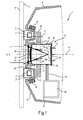
- Fig.1 shows a cross-sectional side view of a non-contact temperature sensing device 1, which is magnetically and thus releasably attached via an adapter 2 on a lateral outer side 3 of a side wall of a cooking utensil in the form of a cooking pot 4.
- the temperature sensing device 1 is preferably mounted in the vicinity of a bottom of the cooking pot 4 in order to be able to reliably determine a cooking temperature of food to be cooked in the cooking pot 4, even if the cooking pot 4 is only partially filled.
- the temperature sensing device 1 has a housing 6 with a disc or puck-like basic shape.
- the adapter 2 is annular and connected to the outside 3 of the cooking pot 4 detachably or permanently connected, for example glued thereto.
- the adapter 2 is sufficiently elastic in order to be able to conform to the curved outer side 3 of the cooking pot 4 and to be able to contact them areally.
- the adapter 2 is for this purpose made of an elastic, thermally resistant base material such as silicone, wherein therein a ferromagnetic Ring 7 is embedded.
- a field of view S of the temperature sensing device 1 is laterally enclosed by the adapter 2 with respect to an optical axis O of the temperature sensing device 1.
- the field of view S forms on the outside 3 of the cooking pot 4 a measuring spot.
- the adapter 2 consequently also serves as circumferential lateral protection, for example to prevent mechanical or chemical stress.
- In the base material of the adapter 2 soot is distributed as a filler, so that the adapter 2 is also opaque and is used to prevent interference on the field of view S.
- the temperature sensing device 1 has a non-contact IR sensor 8, which is directed towards the outside 3 of the cooking pot 4 and which has e.g. one or more thermopiles ("thermopiles") 5 may have.
- the temperature sensing device 1 may thereby contactlessly sense a temperature on the outside 3 of the cooking pot 4.
- the thermopile 5 shown here possibly together with an electronics 52, 53 housed in the form of an ASIC on a metal core plate 5a.
- the adapter 2 has a bottom (not shown) which lies in the field of view S and prevents a direct view of the IR sensor 8 on the outside 3 of the cooking pot 4.
- the floor lies in particular flat on the outside 3 of the cooking pot 4, so that a temperature of the cooking pot 3 is effectively transferred to the ground.
- the bottom serves to provide a known IR radiation characteristic irrespective of the nature of the outside 3 of the cooking pot 3, e.g. of the associated material or its surface texture.
- the temperature sensing device 1 has an adapter 2 facing front side mounting counter area in the form of an annular circumferential recess 9, which is placed on the adapter 2.
- the temperature sensing device 1 may, for example, be clamped onto the adapter 2 with the recess 9.
- the housing 6 has on the inside a permanently magnetic or magnetically attractable body, namely a permanent magnet ring 10 arranged on a side wall of the fastening region 9.
- the permanent magnetic ring 10 of the temperature sensing device 1 attracts the ferromagnetic ring 7 of the adapter 2.
- the ring 10 may also be ferromagnetic while the ring 7 is permanent magnetic.
- both rings 7 and 10 may be permanent magnetic.
- iron-containing or magnetic particles may also be distributed as filling material in the elastic base material.
- an opening 12 into which the IR sensor 8 protrudes In the middle of one of the cooking pot 4 facing the front side 11 of the housing 6 of the temperature sensing device 1 is an opening 12 into which the IR sensor 8 protrudes. As in an enlarged section A in Fig.2 1, the opening 12 is delimited by means of a collar 13 directed into the housing 6, which has an attachment step 15 for attachment of the IR sensor 8.
- the IR sensor 8 may there be glued to the collar 13, for example.
- a permeable window for IR radiation 17 is present on an inner wall 16 of the collar 13 .
- the window 17 may be formed as an IR filter, in particular to pass only a spectral range of the infrared light, which is at least largely detectable or sensible by the thermopile 5.
- the window 17 may also be adapted to attenuate the transmitted IR radiation, in particular to a level which allows an accurate measurement of the temperature, but keeps heating of the IR sensor 8 low by the incident IR radiation.
- the window 17 is provided with a hard coating at least on its front side 17a facing the cooking pot 4.
- the hard coating may e.g. to be a carbon coating.
- a closed peripheral step 18 which is oriented forward (i.e., in the mounted state of the temperature sensing device 1 in the direction of the cooking pot 4).
- the window 17 is placed on the step 18 for mounting from the outside and fastened there with its rear side 17b, e.g. bonded.
- the window 17 may be inserted in a clamping and / or form-locking manner in a lateral annular groove 19 of the collar 13 situated directly above the step 18.
- step 18 By means of the step 18 it is achieved that an inner, free-standing area 17c of the window 17, which does not rest on the step 18, is kept largely free of dirt, etc. can be.
- a user typically the window 17 by means of a cloth oää. cleans and usually turns the cloth on the window 17.
- the inner portion 17 c of the window 17 can be effectively cleaned, while the outer portion 17 d is usually not cleaned and even in addition to dirt u.
- the step 18 blocks a view of the IR sensor 8 on the outer portion 17d of the window 17. An incidence of scattered infrared radiation through the outer portion 17d of the window 17 in the IR sensor 8 is prevented, thus achieving a uniform IR radiation behavior , which in turn improves a reproducible measurement behavior.
- the inner wall 16 of the collar 13 widens forward.
- the inner wall 16 may there have a conical shape in particular there. As a result, the collar 13 does not hinder the field of view of the IR sensor 8 there.
- the IR sensor 8 has a base 20 on which a metallic can 21 is seated.
- the jug 21 has on its front side facing the window 17 a radiation inlet opening 22, through which IR radiation can fall on at least one IR sensor element located in the IR sensor 8.
- the thermopile 5 is disposed on the base 20 via the metal core board 5a.
- the radiation entrance aperture 22 is covered by an IR lens 23 which slightly reduces a (half) aperture angle of the field of view S of the IR sensor 8, e.g. at 11 degrees.
- the lens 23 may also be embodied as an IR filter in order in particular to admit only a spectral range of the infrared light which can be detected or sensed by the thermopile 5.
- a further temperature sensor not shown
- e.g. a contact temperature sensor e.g. a contact temperature sensor.
- the can 21 is heated more strongly in the associated contact region than outside, for example as in the vicinity of the base 20.
- This uneven heat distribution of the can 21 can lead to measurement inaccuracies, since a correlation between a can be tapped off at the electrodes 24 of the IR sensor 8 measurement signal and the associated observed temperature usually for a uniformly heated Jug 21 is specified.
- this preferably consists of a good heat-conducting material, for example metal.
- the can 21 is surrounded on its side wall 25 by a ring 26 of good heat-conducting material, such as metal, the ring 26 is connected to the pot 21 surface to keep a low thermal resistance and high heat flow from the pot 21 to the Ring 26 to reach.
- the ring 26 thus serves as a heat spreading element and helps to dissipate the heat of the pot 21 from a contact area with the housing 6.
- the ring 26 may also serve as a heat sink by releasing heat to the air inside the housing. It may be provided with a cooling structure, for example, with cooling fins, fins or cooling pins.
- the ring 26 For a particularly effective heat dissipation of the ring 26 is arranged close to the collar 13, as shown, in particular on the collar 13 placing, since the ring 26 is so particularly close to the contact surface of the pot 21 to the collar 13.
- the ring 26 may in particular be frictionally secured to the jug 21, in addition or alternatively also be adhered thereto, for example by means of a thermal paste.
- the jug 21 may be thermally connected to at least one functional element of the temperature sensing device 1.
- Such functional elements of the temperature sensing device 1 located in the housing 6 may be e.g. an energy storage, e.g. a battery, a radio transmitter, the ring 10, a shield (especially when used with an induction hob), etc.
- at least one electronics e.g. an evaluation electronics, at least one shield, e.g. against induction, at least one light source, e.g. Lamp, and / or at least one switch, etc. are located.
- the thermal connection with at least one functional element is shown here purely by way of example with reference to a thermal connection of the jug 21 with a battery holder 27 accommodated in the housing 6 with the battery 28 inserted.
- the battery 28 may include, for example, one or more 3-volt button cells.
- the battery holder 27 is connected to the can 21 via a metal strip 29.
- the metal strip 29 is placed at one end around the side wall 25 of the pot 21 to achieve a low thermal resistance.
- At the other end of the metal strip 29 is connected to a metallic volume of the battery holder 27, for example, an electrical ground terminal, and thus thermally with the comparatively large battery 28.
- the pot 21 is also electrically grounded. Overall, therefore, serve the metal strip 29, the battery holder 27 and the battery 28 as a heat spreader.
- the metal strip 29 may contact the ring 26 and thus serve to enhance the heat dissipation capability of the ring 26.
- the ring 10 may be thermally connected to the jug 21, e.g. by means of at least one metallic connecting element (not shown).
- the metal core board 5a may be thermally connected to the jug 21, e.g. by means of at least one so-called “thermal vias" and / or by means of thermal paste.
- the recess 9 of the housing 6, which can be placed on the adapter 2 is separated from the collar 13 by a lateral air gap 30.
- a heat flow of the heat transferred between the adapter 2 and the recess 9 to the can 21 is limited by the comparatively thin wall of the front side 11 of the housing 6.
- FIG. 3 shows a cross-sectional side view of a non-contact temperature sensing device 41, which is similar to the temperature sensing device 1 constructed.
- a flatter IR sensor 42 is now housed in the housing 43.
- the surrounding shallower metallic can 44 surrounding ring 26 now occupies almost the entire exposed side wall 45 of the pot 44, which allows a particularly effective heat dissipation. Since the distance from the window 17 to the thermopile 5 is considerably less than in the temperature sensing device 1, an IR lens 23 is dispensed with in favor of a simple IR-transparent viewing window 46. In addition, no air gap 30 is present in this embodiment, which makes the housing 43 easier to manufacture.
- the recess 47 now also serves as a collar to the attachment of the IR sensor 42 and has, among other things, the opening 12 and the attachment step 15.
- the visor 46 may also serve as an IR damper.
- FIG 4 1 shows a possible functional diagram of the temperature sensing device 1 or 41.
- the temperature sensing device 1 or 41 has the battery 28 for the power supply on.
- the battery 28 feeds electronics 51 housed in the housing 6 or 43, as indicated by the arrow P1.
- the electronics 51 serves to switch on and off the temperature sensing device 1 and to monitor the battery 28, for example for monitoring a battery voltage.
- the electronics 51 controls a power supply of the IR sensor 8, as indicated by the arrow P2.
- the IR sensor 8 there are housed a measuring equipment 52 (e.g., measuring electronics) connected to the thermopile 5, and a first data processing means 53 arranged together on a metal core board 5a, e.g. in the form of an ASIC 54.
- the measuring device 52 serves to determine a temperature on the output signals of the at least one thermopile 5, e.g. through digitization and standardization of the measuring signals.
- the first data processing device 53 may further process the temperature values output by the measuring technique 52 as indicated by the arrow P3, e.g. for a status determination with thresholds compare.
- the data processing may additionally or alternatively be performed outside the IR sensor 8 by means of a second data processing device 55.
- possible states may be a determination that the thermopile 5, the IR sensor 8, or the temperature sensing device 1 or 41 is too hot, that a battery voltage of the battery 28 is too low, the temperature sensing device 1 has been turned on, or the temperature sensing device 1 turns off, include.
- the temperature data and possibly statuses are forwarded to a radio module 56, as indicated by the arrow P4.
- a power supply of the radio module 56 as indicated by the arrow P2, also controlled by the electronics 51.
- the radio module 56 can transmit the temperature data and possibly statuses and further information (s) to a hob F via a radio link B (eg according to the Bluetooth protocol).
- the hob F here has a plurality of cooking areas K, wherein the cooking pot 4 is stored on one of these cooking places K.
- the cooking zones K may have, for example, radiant heaters or induction coils for the energy output to the cooking pot 4.
- the radio module 56 may serve unidirectionally as a radio transmitter for data transmission only to the hob or bi-directionally may also receive data via the radio link B from the hob F, eg for the assignment of an identifier.
- the hob F can set the cooking position K on which the cooking pot 4 is stored on the basis of the information sent from the temperature sensing device 1 or 41.
- an energy input from this cooking point K is adjustable on the cooking pot 4, e.g. an electric power and thus a transferred to the cooking pot 4 electrical energy.
- a control loop for regulating the temperature of the cooking pot 4 or of cooking material located therein can be provided. In comparison with a contact probe, a particularly short settling time of the control loop is achieved with high accuracy.
- the hotplate K may e.g. be turned off if a status indicates overheating of the temperature sensing device 1 or 41.
- the electronics 51 also controls a power supply to one or more user interfaces 57, as indicated by the arrow P5.
- the at least one user interface 57 may e.g. one or more visual and / or audible indicators, such as at least one lamp, e.g. LED, and / or include a speaker.
- the user interface 57 may e.g. also include at least one control element such as a reset button and / or an on / off switch. For example, by turning on the temperature sensing device 1 or 41 by means of an on / off switch, a corresponding electrical signal may be sent to the electronics 51, as indicated by the arrow P6. This may include activation of the electronics 51.
- this may e.g. send a corresponding switch-off signal to the data processing device 53 and / or 55, as indicated by the arrow P7.
- the data processing device 53 and / or 55 may then go through a shutdown routine which is e.g. a transmission of a corresponding status to the radio module 56, which sends an associated message to the hob F.
- the data processing device 53 and / or 55 may also send out a switch-off command to the electronics 51, as indicated by the arrow P8, to turn them off, in particular in order to electrically isolate the battery 28 from the rest of the electrical circuit.
- the data processing device 53 and / or 55 may also, as indicated by the arrow P9, drive at least one user interface 57, eg a lamp or a loudspeaker, eg to indicate a current operating status.
- a permanent light lamp may be applied to a normally operating temperature sensing device 1 or 41 indicates a flashing lamp in the event of an error such as low battery voltage or overheating.
- the temperature sensing device 41 may also have an air gap 30.
- the window 17 may be used as an IR beam-shaping element, e.g. as an IR lens.
- a potting compound may serve as a thermal mass at least one electronics.
- a number may include exactly the specified number as well as a usual tolerance range, as long as this is not explicitly excluded.
Landscapes
- Physics & Mathematics (AREA)
- General Physics & Mathematics (AREA)
- Spectroscopy & Molecular Physics (AREA)
- Cookers (AREA)
- Radiation Pyrometers (AREA)
Abstract
Description
- Die Erfindung betrifft eine Temperaturabfühlvorrichtung zum berührungslosen Abfühlen einer Temperatur eines Gargeschirrs, aufweisend: ein Gehäuse mit einem darin angeordneten, durch eine Öffnung in dem Gehäuse gerichteten IR-Sensor und eine in der Öffnung vor dem IR-Sensor angeordnete, für IR-Strahlung durchlässige IR-Durchlichtoptik.
- In der
DE 1 739 099 U wird eine Vorrichtung zur Überwachung der Temperatur bei Elektrowärmegeräten beschrieben, die beim Erreichen einer bestimmten Temperatur des Wärmegeräts bzw. des zu erwärmenden Gutes den Heizstrom ganz oder teilweise abschalten und gegebenenfalls bei sinkender Temperatur wieder zuschalten kann, wobei im letzteren Falle die Temperatur etwa auf dem gleichen vorher einstellbaren Wert gehalten wird. In derDE 1 739 099 U wird es auch beschrieben, eine thermobimetallbetätigte Vorrichtung mit einem Magneten zu versehen, so dass sie beim Ansetzen an der Wandung eines Kochtopfes magnetisch gehalten wird. In derDE 1 739 099 U wird ferner beschrieben, dass ein Überwachungsglied, z.B. ein Bimetallregler, unter Vermittlung eines oder mehrerer Saugnäpfe aus elastischem Werkstoff, z.B. Natur- oder Silikon-Kautschuk, an der zu überwachenden Stelle festlegbar ist. -
DE 41 29 196 A1 offenbart eine Vorrichtung zur Regelung der Heizleistung einer Kochstelle, insbesondere für einen Elektroherd, mit Hilfe eines an der Außenwand des Kochgefäßes anliegenden Wandberührungssensors, mit dem der Ist-Wert der Temperatur des Gefäßinhalts näherungsweise festgestellt wird. Der Wandberührungssensor soll zur bequemen Benutzung in Verbindung mit einer ebenflächigen Heizfläche ausgebildet werden. Dies wird dadurch erreicht, dass der Wandberührungssensor in Verbindung mit einem auf der Herdplatte bzw. auf dem Kochfeld befestigten Anlagestück gehaltert ist. -
EP 0 779 051 A1 offenbart einen Topf für eine sensorgesteuerte Garungseinheit, die aus Gargerät, Sensorik und Kochfeld besteht, wobei ein der sensorgesteuerten Garungseinheit zugeordneter Infrarotsensor kochstellenbezogen leicht erhöht oberhalb des Kochfeldes angeordnet und in einer konstruktiven Funktionseinheit integriert ist, so dass in der sensorgesteuerten Garungseinheit Kochfeld, Gargerät und Sensorik systemhaft miteinander verbunden, aufeinander angepasst und optimierbar sind, wobei eine Systemertüchtigung zum Infrarotsensor-Garen für Normaltöpfe durch eine Beschichtung mit Folie, Lack oder anderen Mitteln herbeiführbar ist, wobei diese Beschichtung eine restlos lösbare ist. - Es ist die Aufgabe der vorliegenden Erfindung, die Nachteile des Standes der Technik zumindest teilweise zu überwinden und insbesondere eine verbesserte Möglichkeit zur berührungslosen Temperaturabfühlung an einem Gargeschirr der betreffenden Art bereitzustellen. Insbesondere soll eine besser reproduzierbare Temperaturabfühlung ermöglicht werden.
- Diese Aufgabe wird gemäß den Merkmalen der unabhängigen Ansprüche gelöst. Bevorzugte Ausführungsformen sind insbesondere den abhängigen Ansprüchen entnehmbar.
- Die Aufgabe wird gelöst durch eine Temperaturabfühlvorrichtung zum berührungslosen Abfühlen einer Temperatur eines Gargeschirrs, aufweisend: ein Gehäuse mit einem darin angeordneten, durch eine Öffnung in dem Gehäuse gerichteten IR-Sensor und eine in der Öffnung vor dem IR-Sensor angeordnete, für IR-Strahlung durchlässige IR-Durchlichtoptik, wobei die IR-Durchlichtoptik einen inneren Bereich und einen darum seitlich umlaufenden äußeren Bereich aufweist, welcher äußere Bereich mittels des Gehäuses gegenüber dem IR-Sensor abgeschattet ist und an einer Vorderseite der IR-Durchlichtoptik zumindest teilweise freiliegt.
- Dabei wird ausgenutzt, dass ein Nutzer der Temperaturabfühlvorrichtung die Durchlichtoptik typischerweise so reinigt, dass er mittels eines Tuchs über deren Vorderseite wischt. Die zugehörige Wischbewegung ist in der Regel eine Drehbewegung. Dadurch wird der innere Bereich gereinigt, während Schmutz oder andere Ablagerungen in dem schwerer zugänglichen, aber freiliegenden äußeren Bereich verbleiben oder durch die Wischbewegung sogar von dem inneren Bereich in den äußeren Bereich transportiert werden. Der äußere Bereich mag zwar grundsätzlich ebenfalls gereinigt werden, beispielsweise mittels eines Wattestäbchens o.ä., jedoch ist dies eher unüblich. Eine Schmutzablagerung verändert die Durchlasscharakteristik, so dass eine Reproduzierbarkeit und/oder eine Genauigkeit einer Temperaturmessung leiden. Dadurch, dass der äußere Bereich mittels des Gehäuses gegenüber dem IR-Sensor abgeschattet ist, liegt er nicht mehr im Sichtfeld des IR-Sensors und beeinflusst damit auch das Messverhalten des IR-Sensors nicht. So wird eine besser reproduzierbare und ggf. auch genauere Temperaturabfühlung oder Temperaturmessung ermöglicht.
- Die Temperaturabfühlvorrichtung mag insbesondere zum berührungslosen Abfühlen einer Temperatur einer Seitenwand eines Gargeschirrs vorgesehen sein.
- Das Gehäuse besteht zur Unterdrückung einer Wärmeleitung bevorzugt aus Kunststoff.
- Der IR-Sensor ist ein berührungslos arbeitender IR-Sensor. Er mag zur Umwandlung von infraroter (IR-) Strahlung ein oder mehrere Sensorelemente aufweisen, z.B. Thermosäulen oder "Thermopiles". Dies ermöglicht eine besonders verzögerungsarme und damit schnelle Temperaturerfassung. Zudem ist eine berührungslose Temperaturmessung wenig fehleranfällig.
- Der IR-Sensor mag einen Boden oder Sockel zur Anordnung des mindestens einen Sensorelements aufweisen. Der Sockel mag auch mindestens ein elektrisches Anschlusselement aufweisen, z.B. mindestens einen durch den Sockel durchgeführten elektrischen Anschluss. Der IR-Sensor mag ferner mindestens eine Verarbeitungsschaltung zur Verarbeitung der von dem mindestens einen Sensorelement ausgegebenen Messsignale aufweisen, z.B. zu ihrer Digitalisierung. Die Verarbeitungsschaltung mag zusammen mit dem mindestens einen Sensorelement auf einer gemeinsamen Platine angeordnet sein. Die Platine mag zur effektiven Wärmespreizung und Wärmeabfuhr eine Metallkernplatine sein.
- Der IR-Sensor mag ferner ein mit dem Sockel verbundenes Abdeckelement aufweisen, insbesondere in Form einer Kanne, speziell einer metallischen Kanne. Das Abdeckelement weist im Sichtfeld des mindestens einen Sensorelements eine Öffnung ("Strahlungseintrittsöffnung") zum Eintritt von IR-Strahlung auf das mindestens eine Sensorelement auf. Die Strahlungseintrittsöffnung ist bevorzugt für von dem mindestens einen Sensorelement detektierbares IR-Licht durchlässig.
- Der IR-Sensor ist also dazu eingerichtet und angeordnet, durch die Öffnung in dem Gehäuse und dabei durch den inneren Bereich der IR-Durchlichtoptik einfallende Lichtstrahlung zu detektieren.
- Es ist eine Ausgestaltung, dass die IR-Durchlichtoptik auf einer nach vorne (d.h. in Richtung des abzufühlenden Gargeschirrs) gerichteten Stufe des Gehäuses im Bereich der Öffnung angeordnet ist und die Stufe als Blende gegenüber dem IR-Sensor dient. Diese Ausgestaltung weist den Vorteil auf, dass die IR-Durchlichtoptik einfach montierbar ist, z.B. durch Aufsetzen auf die mit einem Haftmittel versehene Stufe. Zudem ist eine Stufe einfach bei der Herstellung des Gehäuses berücksichtigbar, z.B. durch entsprechende Gestaltung eines Werkzeugs. So kann die Stufe an einem spritzgegossenen Gehäuse ohne Einbringung eines Hinterschnitts umgesetzt werden. Die Stufe ist vorzugsweise eine umlaufend geschlossene Stufe.
- Es ist noch eine Ausgestaltung, dass die IR-Durchlichtoptik im Bereich ihres Seitenrands in einer Aussparung des Gehäuses zumindest formschlüssig gehalten wird. Dies bewirkt vorteilhafterweise einen besonders sicheren Sitz der IR-Durchlichtoptik. Die Aussparung mag beispielsweise eine umlaufende Ringnut sein. Eine Tiefe der Aussparung ist vorzugsweise so gering, dass die IR-Durchlichtoptik in die Aussparung einschnappbar ist, insbesondere durch elastische Verformung der IR-Durchlichtoptik und/oder des Gehäuses.
- Es ist eine weitere Ausgestaltung, dass die IR-Durchlichtoptik in ihrem Kontaktbereich mit dem Gehäuse zumindest teilweise IR-reflektierend ausgebildet ist. Dadurch wird vorteilhafterweise eine Einstreuung von Wärmestrahlung von dem Gehäuse in die IR-Durchlichtoptik unterdrückt. Die IR-Durchlichtoptik mag in ihrem Kontaktbereich insbesondere hochgradig glatt oder glänzend ausgebildet sein. Die IR-Durchlichtoptik mag in ihrem Kontaktbereich insbesondere IR-verspiegelt ausgebildet sein, z.B. durch Vorsehen einer entsprechenden Beschichtung.
- Es ist noch eine weitere Ausgestaltung, dass die IR-Durchlichtoptik zumindest an ihrer Vorderseite mit einer Hartbeschichtung versehen ist. Die Hartbeschichtung mag insbesondere eine Carbonbeschichtung sein. Dies sichert eine gute Reproduzierbarkeit der Temperaturmessung auch nach wiederholtem Abwischen der IR-Durchlichtoptik.
- Es ist ferner eine Ausgestaltung, dass die IR-Durchlichtoptik IR-strahlungsdämpfend ausgebildet ist. So wird der Vorteil erzielt, dass die durchgelassene IR-Strahlung auf eine Intensität einstellbar ist, welche einerseits eine genaue Messung der Temperatur zulässt, andererseits aber eine Aufwärmung des IR-Sensors durch die einfallende IR-Strahlung gering hält. Auch dies unterstützt eine Reproduzierbarkeit der Temperaturmessung.
- In der Öffnung mag sich mindestens eine IR-Durchlichtoptik befinden, also entweder eine einzelne IR-Durchlichtoptik oder mehrere IR-Durchlichtoptiken, die vorzugsweise hintereinander geschaltet sind.
- Es ist auch eine Ausgestaltung, dass die IR-Durchlichtoptik ein strahlformbewahrendes Fenster ist oder aufweist. Durch ein solches Fenster wird eine Form des einfallenden IR-Lichtbündels praktisch nicht verändert. Ein solches Fenster mag z.B. in Form einer scheibenförmigen Platte vorliegen.
- Es ist außerdem eine Ausgestaltung, dass die IR-Durchlichtoptik strahlformend ist, insbesondere eine IR-Linse ist. So kann ein Öffnungswinkel des Sichtfensters auf einfache Weise eingestellt werden.
- Es ist eine Weiterbildung, dass die Temperaturabfühlvorrichtung dazu eingerichtet ist, für ihren Betrieb an einem Gargeschirr befestigt zu sein. Dies mag durch direkte Befestigung an dem Gargeschirr geschehen, z.B. durch eine magnetische Haftung, oder indirekt über einen an dem Gargeschirr befestigten Adapter. Die Temperaturabfühlvorrichtung ist insbesondere eine eigenständig durch einen Nutzer des Gargeschirrs handhabbare Vorrichtung.
- Es ist zudem eine Ausgestaltung, dass die Temperaturabfühlvorrichtung mit ihrer Vorderseite auf einen an dem Gargeschirr angebrachten Adapter aufsetzbar ist. Dies ermöglicht eine Anbringung, welche die Reproduzierbarkeit der Temperaturmessung noch weiter unterstützt. Denn der Adapter ermöglicht eine immer gleiche Ausrichtung der Temperaturabfühlvorrichtung in Bezug auf das Gargeschirr, an welchem der Adapter befestigt ist. Zudem mag der Adapter so ausgebildet sein, dass er nicht von dem Gargeschirr abgestrahltes IR-Streulicht blockiert. Ferner mag der Adapter einen in dem Sichtfeld des IR-Sensors liegenden Bereich aufweisen, welcher mit dem Gargeschirr thermisch gekoppelt ist (indem der Bereich z.B. flächig an dem Gargeschirr aufliegt) und definierte IR-Abstrahlbedingungen erfüllt. Folglich misst der IR-Sensor die Temperatur dieses Bereichs, so dass die Temperaturmessung nicht durch ein Material oder eine Oberflächenbeschaffenheit des Gargeschirrs im Sichtfeld des IR-Sensors verfälscht wird.
- Der Adapter ist insbesondere elastisch soweit verformbar, dass er großflächig auch auf eine gekrümmte Außenseite eines Gargeschirrs aufsetzbar ist. Die Temperaturabfühlvorrichtung ist an dem Adapter insbesondere magnetisch haftend befestigbar.
- Es ist noch eine Ausgestaltung, dass die Temperaturabfühlvorrichtung eine Kommunikationseinrichtung zur Übertragung zumindest von abgefühlten oder gemessenen Temperaturwerten aufweist. So wird eine besonders vielseitige und flexible Erwärmung von Gargut ermöglicht. Die Kommunikationseinrichtung mag Daten insbesondere drahtlos übertragen, z.B. über Funk, beispielsweise auf der Grundlage eines Bluetooth-Protokolls, oder über eine IR-Datenverbindung. Die Temperaturabfühlvorrichtung mag über die Kommunikationseinrichtung auch Statusdaten übertragen, z.B. über eine Betriebsbereitschaft, ein Abschalten, ein Vorliegen einer niedrigen Batteriespannung, eine mögliche oder bereits eingetretene Überhitzung usw.
- Es ist auch noch eine Ausgestaltung, dass die Temperaturabfühlvorrichtung aufweist: ein Gehäuse mit einem darin angeordneten IR-Sensor mit mindestens einem Sensorelement, welcher IR-Sensor ein Abdeckelement aufweist, das im Sichtfeld des mindestens einen Sensorelements eine Strahlungseintrittsöffnung aufweist, wobei das Abdeckelement an dem Gehäuse aufliegt und das Abdeckelement mit mindestens einem in dem Gehäuse untergebrachten Wärmespreizungselement wärmeleitend verbunden ist. Dadurch wird eine Temperaturdifferenz an der Abdeckung vermindert, welche sich zwischen einer Auflagefläche mit dem Gehäuse und anderen Bereichen der Abdeckung bildet. Dazu stellt das Wärmespreizungselement eine thermische Masse bereit, auf welche sich die in der Abdeckung gespeicherte Wärme übertragen lässt, was einen Abbau von Wärmespitzen und damit eine Vereinheitlichung eines Temperaturniveaus der Abdeckung bewirkt. Ein Wärmeübertrag von dem Gehäuse auf die Abdeckung kann sich beispielsweise durch die Nähe des Gehäuses zu dem Gargeschirr, an welchem es befestigt ist, oder durch eine direkte Strahlungseinwirkung einer teilweise freiliegenden Kochstelle ergeben. Diese Temperaturdifferenz wirkt einer Einhaltung einer Messgenauigkeit entgegen, da sie eine ungleichmäßige, schwer erfassbare Messumgebung für das mindestens eine in dem IR-Sensor untergebrachte Sensorelement erzeugt. Jedoch wird zur genauen Berechnung einer Temperatur mittels des IR-Sensors eine gleichmäßige Erwärmung der Abdeckung vorausgesetzt und diese Temperatur ggf. auch lokal an der Abdeckung gemessen, z.B. mittels einer in dem IR-Sensor untergebrachten Temperaturmesseinrichtung, insbesondere eines Kontakttemperatursensors. Stimmt die tatsächliche Temperatur der Abdeckung nicht über das gesamte Sichtfeld des mindestens einen Sensorelements mit der von der Temperaturmesseinrichtung ermittelten Temperatur überein, kommt es zu Messfehlern. Dies ist insbesondere der Fall bei einer Verwendung von Thermosäulen als Sensorelement(en).
- Das Wärmespreizungselement weist eine ausreichende thermische Masse und damit Wärmeaufnahmekapazität auf, um die Temperaturspitzen der Abdeckung praktisch sinnvoll zu reduzieren.
- Das Wärmespreizungselement mag insbesondere auch als Kühlkörper dienen und dazu insbesondere eine dedizierte (nur für diesen Zweck vorgesehene) Kühlstruktur aufweisen, z.B. umfassend Kühlrippen, Kühlstifte usw.
- Dass ein Wärmespreizungselement mit der Abdeckung wärmeleitend verbunden ist, mag insbesondere umfassen, dass das Wärmespreizungselement an der Abdeckung aufliegt. Dies mag in direktem Kontakt oder über eine dünne Schicht mit geringem Wärmewiderstand geschehen. Der direkte Kontakt mag z.B. durch einen Reibschluss und/oder einen Stoffschluss (z.B. durch ein Verschweißen) hergestellt werden. Die dünne Schicht mag beispielsweise eine doppelseitig klebende Folie, eine Lotschicht oder eine Schicht aus Wärmeleitpaste o.ä. sein.
- Ein Wärmespreizungselement mag mit der Abdeckung auch über eine dedizierte Wärmebrücke verbunden sein. Eine dedizierte Wärmebrücke ist insbesondere ein speziell zur Wärmeleitung vorgesehenes, gut wärmeleitendes Element, insbesondere mit einer Wärmeleitfähigkeit von mehr als 10 W / (m·K). Die Wärmebrücke mag insbesondere ein Element sein, durch welches kein Betriebsstrom fließt, also kein "Leitungselement" ist. Als Wärmebrücke mag also insbesondere nicht eine elektrische Leiterbahn, ein elektrischer Anschluss oder ein elektrischer Verbindungsdraht verstanden werden. Das Material der Wärmebrücke mag elektrisch leitfähig sein, z.B. aus Metall, oder mag elektrisch isolierend sein, z.B. aus Keramik, z.B. aus AIN.
- Es ist eine Ausgestaltung, dass das Abdeckelement eine metallische Kanne ist. Die metallische Kanne mag insbesondere aus Eisenblech, Aluminium oder Kupfer bestehen. Die metallische Kanne ermöglicht vorteilhafterweise eine effektive Wärmeableitung innerhalb der Abdeckung und damit bereits eine verbesserte Homogenisierung der Temperatur der Abdeckung. Außerdem ist eine solche Abdeckung einfach und preiswert herstellbar. Zudem lassen sich Wärmespreizelemente einfach und mit geringem Wärmeübergangswiderstand anbringen, z.B. durch Anlöten, Anschweißen oder Ankleben.
- Es ist noch eine Ausgestaltung, dass die Strahlungseintrittsöffnung vorderseitig an dem Abdeckelement angeordnet ist und das mindestens eine Wärmespreizungselement an einer Seitenwand der Abdeckung anliegt. Die Strahlungseintrittsöffnung ist aus dem Gehäuse herausgerichtet. Diese Ausgestaltung ermöglicht eine einfache und präzise Befestigung des IR-Sensors an dem Gehäuse, insbesondere im Bereich seiner Vorderseite, und ferner eine großflächige Anbindung des Wärmespreizungselements bzw. einer zugehörigen Wärmebrücke.
- Es ist eine weitere Ausgestaltung, dass mindestens ein Wärmespreizungselement an dem Gehäuse aufliegt. So kann bereits Wärme des Gehäuses im Bereich des IR-Sensors abgeführt werden, wodurch sich ein Wärmeübertrag auf den IR-Sensor verringert und sich folglich eine Temperaturdifferenz in der Abdeckung vermindert.
- Es ist noch eine weitere Ausgestaltung, dass das Wärmespreizungselement ein an dem Abdeckelement auf- oder anliegender metallischer Körper ist. Dies ergibt eine besonders starke und schnelle Wärmeableitung von der Abdeckung auf das Wärmespreizungselement. Der Körper mag z.B. aus Stahl, Aluminium oder Kupfer bestehen. Das Wärmespreizungselement mag insbesondere ein dediziertes Wärmespreizungselement sein, das keine Funktion außer einer Wärmeableitung von der Abdeckung aufweist.
- Das Wärmespreizungselement ist für eine einfache Anbringung und eine große Wärmeübertragungsfläche insbesondere als ein Ring ausgestaltet. Der Ring mag insbesondere auf eine Seitenwand der Kanne aufgezogen sein. Der Ring mag auch als Kühlkörper dienen und ausgebildet sein.
- Es ist außerdem eine Ausgestaltung, dass das mindestens eine Wärmespreizungselement mindestens ein Funktionselement der Temperaturabfühlvorrichtung ist. Dadurch werden Elemente der Temperaturabfühlvorrichtung zur Wärmeableitung von der Abdeckung herangezogen, die auch, insbesondere primär, eine andere Funktion aufweisen, sich aber auch als Wärmespreizungselement eignen. Dies erlaubt einen besonders preiswerten und kompakten Aufbau der Temperaturabfühlvorrichtung.
- Es ist auch eine Ausgestaltung, dass ein Wärmespreizungselement, insbesondere ein Funktionselement, mit dem Abdeckelement über eine dedizierte Wärmebrücke verbunden ist. So lässt sich eine vielgestaltige und flexible Positionierung des Wärmespreizungselements, insbesondere Funktionselements, in dem Gehäuse erreichen. Die Wärmebrücke mag z.B. ein Metallstreifen sein. Die Verwendung eines Metallstreifens weist den Vorteil auf, dass sich dieser flächig um eine Seitenwand der Abdeckung herum auflegen lässt.
- Es ist ferner eine Ausgestaltung, dass ein mit der Abdeckung verbundenes Funktionselement eine Batteriehalterung und/oder eine Batterie ist. Eine Nutzung der Batteriehalterung als wärmespreizendes Funktionselement weist den Vorteil auf, dass die Batteriehalterung als Blechteil sich einfach über eine Wärmebrücke mit der Abdeckung thermisch verbinden lässt.
- Es ist auch noch eine Ausgestaltung, dass die Temperaturabfühlvorrichtung mindestens einen magnetisch anziehbaren Körper zur magnetischen Befestigung der Temperaturabfühlvorrichtung aufweist und der magnetisch anziehbare Körper ein mit der Abdeckung verbundenes Funktionselement ist.
- Es ist zudem eine Ausgestaltung, dass eine in dem IR-Sensor untergebrachte Metallkernplatine ein mit der Abdeckung verbundenes Funktionselement ist. So lässt sich ein besonders kompakter Aufbau erreichen. Insbesondere lässt sich ein Metallkern der Metallkernplatine mit der Abdeckung thermisch verbinden, beispielsweise über einen oder mehrere metallische Streifen, welche einerseits innen an der Abdeckung angebracht sind und andererseits an freiliegenden Bereichen der Metallkernplatine oder an thermischen Vias zu dem ansonsten bedeckten Metallkern.
- Es ist noch eine Ausgestaltung, dass eine Abschirmung ein mit der Abdeckung verbundenes Funktionselement ist. Die Abschirmung mag z.B. zum Schutz von Funktionselementen der Temperaturabfühlvorrichtung gegenüber magnetischen Wechselfeldern dienen. Dies mag insbesondere zur Verwendung mit Induktionskochfeldern vorteilhaft sein. Diese Ausgestaltung weist den Vorteil auf, dass eine Abschirmung eine eher große Masse aufweist, wodurch eine hohe thermische Masse erreicht wird, und zudem flächig verteilt ist, was eine Wärmeableitung von der Abschirmung erleichtert.
- Die Aufgabe wird auch gelöst durch ein Gargeschirr, das mit mindestens einer Temperaturabfühlvorrichtung wie oben beschrieben ausgerüstet ist.
- Insbesondere falls die Temperaturabfühlvorrichtung eine Kommunikationseinrichtung zur Übertragung von abgefühlten oder gemessenen Temperaturwerten aufweist, wird die Aufgabe auch gelöst durch ein System aus einem Gargeschirr und einem Gargerät, wobei das Gargerät insbesondere eine Kommunikationseinrichtung zum Empfang der von der Temperaturabfühlvorrichtung übermittelten Temperaturwerte aufweist.
- Das Gargerät ist insbesondere dazu eingerichtet, einen Energieübertrag auf das Gargeschirr auf einer Grundlage der übertragenen Temperaturwerte anzupassen. Dadurch wird insbesondere eine Regelung oder Steuerung einer Temperatur des Kochgeschirrs oder des in dem Kochgeschirr befindlichen Garguts auf eine durch einen Nutzer oder durch ein Garprogramm vorgebbare Soll-Temperatur ermöglicht. Das Gargerät mag auch dazu eingerichtet sein, einen Energieübertrag auf einer Grundlage von durch die Temperaturabfühlvorrichtung übermittelter Statusinformation anzupassen, z.B. eine Kochstelle abzuschalten, falls die Temperaturabfühlvorrichtung eine Überhitzung signalisiert.
- Die Energieübertragung von der Kochstelle auf das Gargeschirr mag z.B. durch Wärmestrahlung (z.B. bei Heizkörper aufweisenden Kochstellen) oder mittels eines magnetischen Wechselfelds (z.B. bei einem Induktionskochfeld) geschehen.
- Das Gargerät weist vorzugsweise ein Kochfeld auf. Es mag beispielsweise ein eigenständiges Kochfeld oder eine Ofen/Kochfeld-Kombination sein, z.B. ein Herd mit einem Backofen und einem darüber angeordneten Kochfeld.
- Die oben beschriebenen Eigenschaften, Merkmale und Vorteile dieser Erfindung sowie die Art und Weise, wie diese erreicht werden, werden klarer und deutlicher verständlich im Zusammenhang mit der folgenden schematischen Beschreibung von Ausführungsbeispielen, die im Zusammenhang mit den Zeichnungen näher erläutert werden. Dabei können zur Übersichtlichkeit gleiche oder gleichwirkende Elemente mit gleichen Bezugszeichen versehen sein.
- Fig.1
- zeigt als Querschnitt in Seitenansicht ein Gargeschirr mit einer daran über einen Adapter befestigten Temperaturabfühlvorrichtung gemäß einem ersten Ausführungsbeispiel;
- Fig.2
- zeigt einen vergrößerten Ausschnitt der
Fig.1 ; - Fig.3
- zeigt als Querschnitt in Seitenansicht ein Gargeschirr mit einer daran über einen Adapter befestigten Temperaturabfühlvorrichtung gemäß einem zweiten Ausführungsbeispiel; und
- .Fig.4
- zeigt eine Funktionsskizze der Temperaturabfühlvorrichtung.
-
Fig.1 zeigt als Querschnitt in Seitenansicht eine berührungslos arbeitende Temperaturabfühlvorrichtung 1, welche über einen Adapter 2 magnetisch und also lösbar an einer seitlichen Außenseite 3 einer Seitenwand eines Gargeschirrs in Form eines Kochtopfs 4 befestigt ist. Die Temperaturabfühlvorrichtung 1 ist vorzugsweise in der Nähe eines Bodens des Kochtopfs 4 befestigt, um eine Gartemperatur von in dem Kochtopf 4 befindlichem Gargut auch bei einem nur teilweise gefüllten Kochtopf 4 zuverlässig bestimmen zu können. Die Temperaturabfühlvorrichtung 1 weist ein Gehäuse 6 mit einer scheiben- oder puckähnlichen Grundform auf. - Der Adapter 2 ist ringförmig ausgebildet und mit der Außenseite 3 des Kochtopfs 4 lösbar oder unlösbar verbunden, z.B. daran angeklebt. Der Adapter 2 ist dabei ausreichend elastisch, um sich an die gekrümmte Außenseite 3 des Kochtopfs 4 anschmiegen zu können und sie flächig kontaktieren zu können. Der Adapter 2 ist dazu aus einem elastischen, thermisch beständigen Grundmaterial wie Silikon hergestellt, wobei darin ein ferromagnetischer Ring 7 eingebettet ist. Ein Sichtfeld S der Temperaturabfühlvorrichtung 1 wird durch den Adapter 2 in Bezug auf eine optische Achse O der Temperaturabfühlvorrichtung 1 seitlich umschlossen. Das Sichtfeld S bildet auf der Außenseite 3 des Kochtopfs 4 einen Messfleck. Der Adapter 2 dient folglich auch als umlaufender seitlicher Schutz, z.B. zum Abhalten einer mechanischen oder chemischen Beanspruchung. In dem Grundmaterial des Adapters 2 ist Ruß als Füllstoff verteilt, so dass der Adapter 2 zudem lichtundurchlässig ist und zum Abhalten von Störstrahlung auf das Sichtfeld S dient.
- Die Temperaturabfühlvorrichtung 1 weist einen auf die Außenseite 3 des Kochtopfs 4 gerichteten, berührungslos arbeitenden IR-Sensor 8 auf, der z.B. einen oder mehrere Thermosäulen ("Thermopiles") 5 aufweisen kann. Die Temperaturabfühlvorrichtung 1 mag dadurch berührungslos eine Temperatur an der Außenseite 3 des Kochtopfs 4 abfühlen. Die hier dargestellte eine Thermosäule 5 ist, ggf. zusammen mit einer Elektronik 52, 53 in Form eines ASICs auf einer Metallkernplatine 5a untergebracht.
- In einer Variante weist der Adapter 2 einen Boden (o. Abb.) auf, welcher in dem Sichtfeld S liegt und eine direkte Sicht des IR-Sensors 8 auf die Außenseite 3 des Kochtopfs 4 verhindert. Der Boden liegt insbesondere flächig auf der Außenseite 3 des Kochtopfs 4 auf, so dass eine Temperatur des Kochtopfs 3 effektiv auf den Boden übertragbar ist. Der Boden dient insbesondere zur Bereitstellung einer bekannten IR-Abstrahlcharakteristik unabhängig von der Art der Außenseite 3 des Kochtopfs 3, z.B. von dem zugehörigen Material oder seiner Oberflächenbeschaffenheit.
- Die Temperaturabfühlvorrichtung 1 weist einen dem Adapter 2 zugewandten, vorderseitigen Befestigungsgegenbereich in Form eines ringförmig umlaufenden Rücksprungs 9 auf, der auf den Adapter 2 aufsetzbar ist. Die Temperaturabfühlvorrichtung 1 mag z.B. mit dem Rücksprung 9 klemmend auf den Adapter 2 aufgesteckt sein. Für eine besonders sichere, aber dennoch einfach lösbare Verbindung der Temperaturabfühlvorrichtung 1 an dem Adapter 2 weist das Gehäuse 6 innenseitig einen dauermagnetischen oder magnetisch anziehbaren Körper auf, nämlich hier einen an einer Seitenwand des Befestigungsbereichs 9 angeordneten dauermagnetischen Ring 10. Der dauermagnetische Ring 10 der Temperaturabfühlvorrichtung 1 zieht den ferromagnetischen Ring 7 des Adapters 2 an. Anstelle eines ferromagnetischen Rings 7 mag z.B. auch der Ring 10 ferromagnetisch sein, während der Ring 7 dauermagnetisch ist. Auch können beide Ringe 7 und 10 dauermagnetisch sein. Anstelle eines Rings 7 mögen in dem elastischen Basismaterial auch eisenhaltige oder magnetische Partikel als Füllmaterial verteilt sein.
- In der Mitte einer der dem Kochtopf 4 zugewandten Vorderseite 11 des Gehäuses 6 der Temperaturabfühlvorrichtung 1 befindet sich eine Öffnung 12, in welche der IR-Sensor 8 ragt. Wie in einem vergrößerten Ausschnitt A in
Fig.2 dargestellt, ist die Öffnung 12 mittels eines in das Gehäuse 6 hinein gerichteten Kragens 13 begrenzt, welcher eine Aufsatzstufe 15 zum Aufsatz des IR-Sensors 8 aufweist.. Der IR-Sensor 8 mag dort z.B. mit dem Kragen 13 verklebt sein. - An einer Innenwand 16 des Kragens 13 ist ein für IR-Strahlung durchlässiges Fenster 17 vorhanden. Das Fenster 17 mag als IR-Filter ausgebildet sein, um insbesondere nur einen spektralen Bereich des Infrarotlichts durchzulassen, der zumindest größtenteils von der Thermosäule 5 detektierbar oder sensierbar ist. Das Fenster 17 mag auch dazu eingerichtet sein, die durchgelassene IR-Strahlung zu dämpfen, insbesondere auf ein Niveau, welches eine genaue Messung der Temperatur zulässt, aber eine Aufwärmung des IR-Sensors 8 durch die einfallende IR-Strahlung gering hält.
- Um eine sich durch wiederholtes Reinigen des Fensters 17 verringernde Messgenauigkeit zu verhindern, ist das Fenster 17 zumindest an seiner dem Kochtopf 4 zugewandten Vorderseite 17a mit einer Hartbeschichtung versehen. Die Hartbeschichtung mag z.B. eine Carbonbeschichtung sein.
- Zur Befestigung des Fensters 17 ist in einer Innenwand 16 eine geschlossen umlaufende Stufe 18 vorhanden, welche nach vorne (d.h. im befestigten Zustand der Temperaturabfühlvorrichtung 1 in Richtung des Kochtopfs 4) ausgerichtet ist. Das Fenster 17 wird zu seiner Montage von außen auf die Stufe 18 aufgesetzt und dort mit seiner Rückseite 17b befestigt, z.B. verklebt. Zusätzlich oder anstelle einer Verklebung mag das Fenster 17 in einer direkt oberhalb der Stufe 18 befindlichen seitlichen Ringnut 19 des Kragens 13 klemmend und/oder formschlüssig eingesetzt sein.
- Mittels der Stufe 18 wird erreicht, dass ein innerer, freistehender Bereich 17c des Fensters 17, welcher nicht auf der Stufe 18 aufsitzt, weitgehend frei von Schmutz usw. gehalten werden kann. Ein äußerer, ringförmiger Bereich 17d des Fensters 17, welcher auf der Stufe 18 aufsitzt, mag hingegen schmutzbehaftet sein, ohne dass eine Messgenauigkeit der IR-Sensors 8 leidet. Dabei wird berücksichtigt, dass ein Nutzer typischerweise das Fenster 17 mittels eines Tuchs o.ä. reinigt und dabei üblicherweise das Tuch auf dem Fenster 17 dreht. So kann der innere Bereich 17c des Fensters 17 effektiv gereinigt werden, während der äußere Bereich 17d meist nicht gereinigt wird und sogar zusätzlich mit Schmutz u. dgl. belegt wird. Jedoch blockiert die Stufe 18 eine Sicht des IR-Sensors 8 auf den äußeren Bereich 17d des Fensters 17. Ein Einfallen von infraroter Streustrahlung durch den äußeren Bereich 17d des Fensters 17 in den IR-Sensor 8 wird verhindert und so ein gleichförmiges IR-Einstrahlverhalten erreicht, was wiederum ein reproduzierbares Messverhalten verbessert.
- Ausgehend von dem Fenster 17 weitet sich die Innenwand 16 des Kragens 13 nach vorne auf. Die Innenwand 16 mag dort insbesondere eine kegelschnittartige Form aufweisen. Dadurch behindert der Kragen 13 dort das Sichtfeld des IR-Sensors 8 nicht.
- Der IR-Sensor 8 weist einen Sockel 20 auf, auf dem eine metallische Kanne 21 aufsitzt. Die Kanne 21 weist an ihrer dem Fenster 17 zugewandten Stirnseite eine Strahlungseintrittsöffnung 22 auf, durch die IR-Strahlung auf mindestens ein in dem IR-Sensor 8 befindliches IR-Sensorelement fallen kann. Auch die Thermosäule 5 ist über die Metallkernplatine 5a an dem Sockel 20 angeordnet. Die Strahlungseintrittsöffnung 22 ist mittels einer IR-Linse 23 abgedeckt, welche einen (halben) Öffnungswinkel des Sichtfelds S des IR-Sensors 8 leicht verringert, z.B. auf 11 Grad. Die Linse 23 mag ebenfalls als IR-Filter ausgebildet sein, um insbesondere nur einen spektralen Bereich des Infrarotlichts einzulassen, welcher von der Thermosäule 5 detektierbar oder sensierbar ist. In dem IR-Sensor 8 mag zur Messung einer Temperatur der Kanne 21 ein weiterer Temperatursensor vorhanden sein (o. Abb.), z.B. ein Kontakttemperatursensor.
- Dadurch, dass der IR-Sensor 8 mit seiner Kanne 21 teilweise auf dem Gehäuse 6, hier: auf dem Kragen 13, aufliegt, wird die Kanne 21 in dem zugehörigen Kontaktbereich stärker erwärmt als außerhalb davon, z.B. als in der Nähe des Sockels 20. Diese ungleiche Wärmeverteilung der Kanne 21 kann zu Messungenauigkeiten führen, da eine Korrelation zwischen einem an Elektroden 24 des IR-Sensors 8 abgreifbaren Messsignal und der zugehörigen beobachteten Temperatur üblicherweise für eine gleichförmig erwärmte Kanne 21 angegeben wird. Zur Verringerung der Temperaturunterschiede an der Kanne 21 besteht diese vorzugsweise aus einem gut wärmeleitenden Material, z.B. Metall. Ferner ist die Kanne 21 an ihrer Seitenwand 25 von einem Ring 26 aus gut wärmeleitendem Material, z.B. Metall, umgeben, der Ring 26 ist mit der Kanne 21 flächig verbunden, um einen Wärmewiderstand gering zu halten und einen hohen Wärmefluss von der Kanne 21 auf den Ring 26 zu erreichen. Der Ring 26 dient also als Wärmespreizungselement und hilft, die Wärme der Kanne 21 aus einem Kontaktbereich mit dem Gehäuse 6 abzuleiten. Der Ring 26 mag auch als Kühlkörper dienen, indem er Wärme an die Luft im Inneren des Gehäuses abgibt. Er mag dazu mit einer Kühlstruktur versehen sein, z.B. mit Kühlrippen, Lamellen oder Kühlstiften. Für eine besonders effektive Wärmeableitung ist der Ring 26 nahe an dem Kragen 13 angeordnet, wie gezeigt, insbesondere auf dem Kragen 13 aufsetzend, da der Ring 26 sich so besonders nahe an der Kontaktfläche der Kanne 21 zu dem Kragen 13 befindet. Der Ring 26 mag insbesondere reibschlüssig an der Kanne 21 befestigt sein, zusätzlich oder alternativ auch daran angehaftet sein, z.B. mittels einer Wärmeleitpaste.
- Alternativ oder zusätzlich kann die Kanne 21 mit mindestens einem Funktionselement der Temperaturabfühlvorrichtung 1 thermisch verbunden sein. Solche in dem Gehäuse 6 befindliche Funktionselemente der Temperaturabfühlvorrichtung 1 mögen z.B. einen Energiespeicher, z.B. eine Batterie, einen Funksender, den Ring 10, eine Abschirmung (insbesondere bei Verwendung mit einem Induktionskochfeld) usw. umfassen. Auch mögen sich in oder an dem Gehäuse 6 mindestens eine Elektronik, z.B. eine Auswerteelektronik, mindestens eine Abschirmung, z.B. gegen Induktion, mindestens ein Leuchtmittel, z.B. Lampe, und/oder mindestens ein Schalter usw. befinden.
- Die thermische Verbindung mit mindestens einem Funktionselement ist hier rein beispielhaft anhand einer thermischen Verbindung der Kanne 21 mit einer in dem Gehäuse 6 untergebrachten Batteriehalterung 27 mit eingesetzter Batterie 28 gezeigt. Die Batterie 28 mag z.B. eine oder mehrere 3-Volt-Knopfzellen umfassen. Die Batteriehalterung 27 ist über einen Metallstreifen 29 mit der Kanne 21 verbunden. Der Metallstreifen 29 ist an einem Ende um die Seitenwand 25 der Kanne 21 gelegt, um einen geringen Wärmewiderstand zu erreichen. Mit dem anderen Ende ist der Metallstreifen 29 mit einem metallischen Volumen der Batteriehalterung 27 verbunden, z.B. einem elektrischen Masseanschluss, und damit thermisch auch mit der vergleichsweise großen Batterie 28. In diesem Fall liegt die Kanne 21 elektrisch ebenfalls auf Masse. Insgesamt dienen also der Metallstreifen 29, die Batteriehalterung 27 und die Batterie 28 als ein Wärmespreizelement.
- Zusätzlich oder alternativ mag der Metallstreifen 29 den Ring 26 kontaktieren und so zur Verstärkung der Wärmeableitfähigkeit des Rings 26 dienen.
- Zusätzlich oder alternativ mag der Ring 10 mit der Kanne 21 thermisch verbunden sein, z.B. mittels mindestens eines metallischen Verbindungselements (o. Abb.).
- Zusätzlich oder alternativ mag die Metallkernplatine 5a mit der Kanne 21 thermisch verbunden sein, z.B. mittels mindestens eines sog. "thermischen Vias" und/oder mittels Wärmeleitpaste.
- Zur weiteren Reduzierung einer Temperaturdifferenz an der Kanne 21 ist der auf den Adapter 2 aufsetzbare Rücksprung 9 des Gehäuses 6 von dem Kragen 13 durch einen seitlichen Luftspalt 30 getrennt. Dadurch wird ein Wärmefluss der zwischen dem Adapter 2 und dem Rücksprung 9 übertragenen Wärme zu der Kanne 21 durch die vergleichsweise dünne Wand der Vorderseite 11 des Gehäuses 6 begrenzt.
-
Fig.3 zeigt als Querschnitt in Seitenansicht eine berührungslos arbeitende Temperaturabfühlvorrichtung 41, die ähnlich zu der Temperaturabfühlvorrichtung 1 aufgebaut ist. Jedoch ist nun ein flacherer IR-Sensor 42 in dem Gehäuse 43 untergebracht. Der die zugehörige flachere metallische Kanne 44 umgebende Ring 26 nimmt nun fast die gesamte freiliegende Seitenwand 45 der Kanne 44 ein, was eine besonders effektive Wärmeableitung ermöglicht. Da der Abstand von dem Fenster 17 zu der Thermosäule 5 erheblich geringer ist als bei der Temperaturabfühlvorrichtung 1, wird auf eine IR-Linse 23 zugunsten einer einfachen IR-durchlässigen Sichtscheibe 46 verzichtet. Zudem ist in diesem Ausführungsbeispiel kein Luftspalt 30 mehr vorhanden, was das Gehäuse 43 einfacher herstellen lässt. Der Rücksprung 47 dient nun vielmehr auch als ein Kragen zum Aufsatz des IR-Sensors 42 und weist dazu unter anderem die Öffnung 12 und die Aufsatzstufe 15 auf. Die Sichtscheibe 46 mag auch als IR-Dämpfer dienen. -
Fig.4 zeigt eine mögliche Funktionsskizze der Temperaturabfühlvorrichtung 1 oder 41. Die Temperaturabfühlvorrichtung 1 oder 41 weist zur Stromversorgung die Batterie 28 auf. Die Batterie 28 speist eine in dem Gehäuse 6 oder 43 untergebrachte Elektronik 51, wie durch den Pfeil P1 angedeutet. Die Elektronik 51 dient zum Ein-/und Ausschalten der Temperaturabfühlvorrichtung 1 und zur Überwachung der Batterie 28, z.B. zur Überwachung einer Batteriespannung. Die Elektronik 51 kontrolliert eine Stromversorgung des IR-Sensors 8, wie durch den Pfeil P2 angedeutet. - In dem IR-Sensor 8 sind eine mit der Thermosäule 5 verbundene als Verarbeitungsschaltung dienende Messtechnik 52 (z.B. eine Messelektronik) und eine erste Datenverarbeitungseinrichtung 53 untergebracht, die hier gemeinsam auf einer Metallkernplatine 5a angeordnet sind, z.B. in Form eines ASICs 54. Die Messeinrichtung 52 dient insbesondere einer Bestimmung einer Temperatur auf den Ausgangssignalen der mindestens einen Thermosäule 5, z.B. durch Digitalisierung und Normierung der Messsignale. Die erste Datenverarbeitungseinrichtung 53 mag die von der Messtechnik 52 wie durch den Pfeil P3 angedeutet ausgegebenen Temperaturwerte weiterverarbeiten, z.B. für eine Statusbestimmung mit Schwellwerten vergleichen. Die Datenverarbeitung mag zusätzlich oder alternativ außerhalb des IR-Sensors 8 mittels einer zweiten Datenverarbeitungseinrichtung 55 durchgeführt werden. Mögliche Stati können beispielsweise eine Feststellung, dass die Thermosäule 5, der IR-Sensor 8 oder die Temperaturabfühlvorrichtung 1 oder 41 zu heiß ist, dass eine Batteriespannung der Batterie 28 zu gering ist, dass die Temperaturabfühlvorrichtung 1 eingeschaltet worden ist oder dass sich die Temperaturabfühlvorrichtung 1 ausschaltet, umfassen.
- Von der bzw. den Datenverarbeitungseinrichtungen 53 und/oder 55 werden, wie durch den Pfeil P4 angedeutet, die Temperaturdaten und ggf. Stati an ein Funkmodul 56 weitergeleitet. Eine Stromversorgung des Funkmoduls 56 wird, wie durch den Pfeil P2 angedeutet, ebenfalls durch die Elektronik 51 kontrolliert. Das Funkmodul 56 kann die Temperaturdaten und ggf. Stati und weitere Information(en) über eine Funkverbindung B (z.B. nach dem Bluetooth-Protokoll) an ein Kochfeld F übertragen. Das Kochfeld F weist hier mehrere Kochstellen K auf, wobei der Kochtopf 4 auf einer dieser Kochstellen K abgelegt ist. Die Kochstellen K können zur Energieabgabe an den Kochtopf 4 z.B. Strahlungsheizkörper oder Induktionsspulen aufweisen. Das Funkmodul 56 mag unidirektional als Funksender zur Datenübermittlung nur zu dem Kochfeld dienen oder mag bidirektional auch Daten über die Funkverbindung B von dem Kochfeld F empfangen, z.B. zur Zuweisung einer Kennung.
- Das Kochfeld F kann die Kochstelle K, auf der der Kochtopf 4 abgelegt ist, auf der Grundlage der von der Temperaturabfühlvorrichtung 1 oder 41 übersandten Information einstellen. Insbesondere ist ein Energieeintrag von dieser Kochstelle K auf den Kochtopf 4 einstellbar, z.B. eine elektrische Leistung und damit eine auf den Kochtopf 4 übertragene elektrische Energie. So lässt sich ein Regelkreis zum Regeln der Temperatur des Kochtopfs 4 bzw. von darin befindlichem Gargut bereitstellen. Im Vergleich zu einem Kontaktfühler wird eine besonders kurze Einschwingzeit des Regelkreises bei hoher Genauigkeit erreicht. Durch die Statusinformation mag die Kochstelle K z.B. abgeschaltet werden, falls ein Status eine Überhitzung der Temperaturabfühlvorrichtung 1 oder 41 anzeigt.
- Die Elektronik 51 kontrolliert auch eine Stromversorgung einer oder mehrerer Nutzerschnittstellen 57, wie durch den Pfeil P5 angedeutet. Die mindestens eine Nutzerschnittstelle 57 mag z.B. eine oder mehrere optische und/oder akustische Anzeigeeinrichtungen wie mindestens einen Lampe, z.B. LED, und/oder einen Lautsprecher umfassen. Die Nutzerschnittstelle 57 mag z.B. auch mindestens ein Bedienelement wie eine Reset-Taste und/oder einen Ein-/Aus-Schalter umfassen. Beispielsweise mag durch ein Einschalten der Temperaturabfühlvorrichtung 1 oder 41 mittels eines Ein-/Aus-Schalters ein entsprechendes elektrisches Signal an die Elektronik 51 gesandt werden, wie durch den Pfeil P6 angedeutet. Dies mag eine Aktivierung der Elektronik 51 umfassen. Zum Ausschalten der Temperaturabfühlvorrichtung 1 oder 41 mittels des Ein-/Aus-Schalters mag dieser z.B. ein entsprechendes Ausschaltsignal an die Datenverarbeitungseinrichtung 53 und/oder 55 senden, wie durch den Pfeil P7 angedeutet. Die Datenverarbeitungseinrichtung 53 und/oder 55 mag daraufhin eine Abschaltroutine durchlaufen, welche z.B. ein Aussenden eines entsprechenden Status an das Funkmodul 56 umfasst, welches eine zugehörige Nachricht an das Kochfeld F absetzt. Die Datenverarbeitungseinrichtung 53 und/oder 55 mag dazu auch einen Ausschaltbefehl an die Elektronik 51 aussenden, wie durch den Pfeil P8 angedeutet, um diese auszuschalten, insbesondere um die Batterie 28 von der restlichen elektrischen Schaltung galvanisch zu trennen.
- Die Datenverarbeitungseinrichtung 53 und/oder 55 mag auch, wie durch den Pfeil P9 angedeutet, mindestens eine Nutzerschnittstelle 57 ansteuern, z.B. eine Lampe oder einen Lautsprecher, z.B. um einen aktuellen Betriebsstatus anzuzeigen. Beispielsweise mag eine dauerleuchtende Lampe auf eine normal arbeitende Temperaturabfühlvorrichtung 1 oder 41 hindeutet, eine blinkende Lampe auf einen Fehlerfall wie eine zu niedrige Batteriespannung oder eine Überhitzung.
- Selbstverständlich ist die vorliegende Erfindung nicht auf die gezeigten Ausführungsbeispiele beschränkt.
- So mag beispielsweise auch die Temperaturabfühlvorrichtung 41 einen Luftspalt 30 aufweisen.
- Auch mag das Fenster 17 als IR-strahlformendes Element, z.B. als IR-Linse, ausgebildet sein.
- Zudem mag eine Vergussmasse mindestens einer Elektronik als thermische Masse dienen.
- Allgemein kann unter "ein", "eine" usw. eine Einzahl oder eine Mehrzahl verstanden werden, insbesondere im Sinne von "mindestens ein" oder "ein oder mehrere" usw., solange dies nicht explizit ausgeschlossen ist, z.B. durch den Ausdruck "genau ein" usw.
- Auch kann eine Zahlenangabe genau die angegebene Zahl als auch einen üblichen Toleranzbereich umfassen, solange dies nicht explizit ausgeschlossen ist.
-
- 1
- Temperaturabfühlvorrichtung
- 2
- Adapter
- 3
- Außenseite eines Gargeschirrs
- 4
- Kochtopf
- 5
- Thermosäule
- 5a
- Metallkernplatine
- 6
- Gehäuse der Temperaturabfühlvorrichtung
- 7
- ferromagnetischer Ring des Adapters
- 8
- IR-Sensor
- 9
- ringförmig umlaufender Rücksprung
- 10
- dauermagnetischer Ring der Temperaturabfühlvorrichtung
- 11
- Vorderseite des Gehäuses der Temperaturabfühlvorrichtung
- 12
- Öffnung
- 13
- Kragen
- 15
- Aufsatzstufe des Kragens
- 16
- Innenwand des Kragens
- 17
- Fenster des Kragens
- 17a
- Vorderseite des Fensters
- 17b
- Rückseite des Fensters
- 17c
- Innerer Bereich des Fensters
- 17d
- Äußerer Bereich des Fensters
- 18
- Stufe
- 19
- Ringnut des Kragens
- 20
- Sockel des IR-Sensors
- 21
- Kanne
- 22
- Strahlungseintrittsöffnung
- 23
- IR-Linse
- 24
- Elektrode
- 25
- Seitenwand der Kanne
- 26
- Ring
- 27
- Batteriehalterung
- 28
- Batterie
- 29
- Metallstreifen
- 30
- Luftspalt
- 41
- Temperaturabfühlvorrichtung
- 42
- IR-Sensor
- 43
- Gehäuse
- 44
- Kanne
- 45
- Seitenwand der Kanne
- 46
- IR-Sichtscheibe
- 47
- Rücksprung
- 51
- Elektronik
- 52
- Messtechnik
- 53
- erste Datenverarbeitungseinrichtung
- 54
- ASIC
- 55
- zweite Datenverarbeitungseinrichtung
- 56
- Funkmodul
- A
- Ausschnitt
- B
- Funkverbindung
- F
- Kochfeld
- K
- Kochstelle
- N
- Nutzerschnittstelle
- O
- Optische Achse
- S
- Sichtfeld
Claims (9)
- Temperaturabfühlvorrichtung (1; 41) zum berührungslosen Abfühlen einer Temperatur eines Gargeschirrs (4), aufweisend:- ein Gehäuse (6; 43) mit einem darin angeordneten, durch eine Öffnung (12) in dem Gehäuse (6; 43) gerichteten IR-Sensor (8) und- eine in der Öffnung (12) vor dem IR-Sensor (8) angeordnete, für IR-Strahlung durchlässige IR-Durchlichtoptik (17),dadurch gekennzeichnet, dass- die IR-Durchlichtoptik (17) einen inneren Bereich (17c) und einen darum seitlich umlaufenden äußeren Bereich (17d) aufweist,- welcher äußere Bereich (17d) mittels des Gehäuses (6; 43) gegenüber dem IR-Sensor (8) abgeschattet ist und- der äußere Bereich (17d) an einer Vorderseite (17a) der IR-Durchlichtoptik (17) zumindest teilweise freiliegt.
- Temperaturabfühlvorrichtung (1; 41) nach Anspruch 1, dadurch gekennzeichnet, dass die IR-Durchlichtoptik (17) auf einer nach vorne gerichteten Stufe (18) des Gehäuses (6; 43) im Bereich der Öffnung (12) angeordnet ist und die Stufe (18) als eine Blende gegenüber dem IR-Sensor (8) dient.
- Temperaturabfühlvorrichtung (1; 43) nach einem der vorhergehenden Ansprüche, dadurch gekennzeichnet, dass die IR-Durchlichtoptik (17) im Bereich ihres Seitenrands in einer Aussparung (19) des Gehäuses (6) zumindest formschlüssig gehalten wird.
- Temperaturabfühlvorrichtung (1; 41) nach einem der vorhergehenden Ansprüche, dadurch gekennzeichnet, dass die IR-Durchlichtoptik (17) in ihrem Kontaktbereich mit dem Gehäuse (6; 43) zumindest teilweise IR-reflektierend ausgebildet ist.
- Temperaturabfühlvorrichtung (1; 41) nach einem der vorhergehenden Ansprüche, dadurch gekennzeichnet, dass die IR-Durchlichtoptik (17) zumindest an ihrer Vorderseite (17a) mit einer Hartbeschichtung versehen ist.
- Temperaturabfühlvorrichtung (1; 41) nach einem der vorhergehenden Ansprüche, dadurch gekennzeichnet, dass die IR-Durchlichtoptik (17) IR-strahlungsdämpfend ausgebildet ist.
- Temperaturabfühlvorrichtung (1; 41) nach einem der vorhergehenden Ansprüche, dadurch gekennzeichnet, dass die IR-Durchlichtoptik (17) ein strahlformbewahrendes Fenster (17) ist.
- Temperaturabfühlvorrichtung (1; 41) nach einem der Ansprüche 1 bis 6, dadurch gekennzeichnet, dass die IR-Durchlichtoptik strahlformend ist, insbesondere eine IR-Linse ist.
- Temperaturabfühlvorrichtung (1; 41) nach einem der vorhergehenden Ansprüche, dadurch gekennzeichnet, dass die Temperaturabfühlvorrichtung (1; 41) mit ihrer Vorderseite (9, 11) auf einen an dem Gargeschirr (4) angebrachten Adapter (2) aufsetzbar ist.
Applications Claiming Priority (1)
| Application Number | Priority Date | Filing Date | Title |
|---|---|---|---|
| DE102014200883.2A DE102014200883A1 (de) | 2014-01-20 | 2014-01-20 | Temperaturabfühlvorrichtung zum Abfühlen einer Temperatur eines Gargeschirrs |
Publications (2)
| Publication Number | Publication Date |
|---|---|
| EP2896943A1 true EP2896943A1 (de) | 2015-07-22 |
| EP2896943B1 EP2896943B1 (de) | 2022-04-06 |
Family
ID=52282611
Family Applications (1)
| Application Number | Title | Priority Date | Filing Date |
|---|---|---|---|
| EP15150105.3A Active EP2896943B1 (de) | 2014-01-20 | 2015-01-05 | Temperaturabfühlvorrichtung zum Abfühlen einer Temperatur eines Gargeschirrs |
Country Status (2)
| Country | Link |
|---|---|
| EP (1) | EP2896943B1 (de) |
| DE (1) | DE102014200883A1 (de) |
Cited By (1)
| Publication number | Priority date | Publication date | Assignee | Title |
|---|---|---|---|---|
| EP3040696B1 (de) * | 2014-12-29 | 2024-02-07 | Bosch Automotive Service Solutions Inc. | Kontaktloser infrarottemperatursensor mit drahtlosfunktion |
Families Citing this family (1)
| Publication number | Priority date | Publication date | Assignee | Title |
|---|---|---|---|---|
| CN111271743A (zh) * | 2020-02-25 | 2020-06-12 | 广东美的厨房电器制造有限公司 | 红外传感器组件和微波炉 |
Citations (7)
| Publication number | Priority date | Publication date | Assignee | Title |
|---|---|---|---|---|
| DE1739099U (de) | 1955-06-13 | 1957-02-07 | Alfred Odenwald | Temperaturueberwachungsvorrichtung fuer elektrowaermegeraete. |
| DE4129196A1 (de) | 1991-09-03 | 1993-03-04 | Gaggenau Werke | Vorrichtung zur regelung der heizleistung einer kochstelle |
| JPH08313342A (ja) * | 1995-05-19 | 1996-11-29 | Matsushita Electric Ind Co Ltd | 焦電型赤外線センサ |
| EP0779051A1 (de) | 1995-12-12 | 1997-06-18 | Bosch-Siemens HausgerÀ¤te GmbH | Topf für eine sensorgesteuerte Garungseinheit |
| EP0931496B1 (de) * | 1998-01-23 | 2003-05-07 | Seb S.A. | Küchengerät mit einem Temperatursensor zum Messen seiner Temperatur |
| US20040031274A1 (en) * | 2002-08-17 | 2004-02-19 | Lg Electronics Inc. | Infrared sensor assembly and refrigerator having the infrared sensor |
| US20040057493A1 (en) * | 2002-07-15 | 2004-03-25 | Chuji Ishikawa | Temperature detecting unit and fixing apparatus |
Family Cites Families (3)
| Publication number | Priority date | Publication date | Assignee | Title |
|---|---|---|---|---|
| US6266197B1 (en) * | 1999-12-08 | 2001-07-24 | Amkor Technology, Inc. | Molded window array for image sensor packages |
| US7718970B2 (en) * | 2005-11-25 | 2010-05-18 | Panasonic Electric Works Co., Ltd. | Infrared detection unit using a semiconductor optical lens |
| JP5793679B2 (ja) * | 2009-12-18 | 2015-10-14 | パナソニックIpマネジメント株式会社 | 赤外線センサモジュール |
-
2014
- 2014-01-20 DE DE102014200883.2A patent/DE102014200883A1/de not_active Withdrawn
-
2015
- 2015-01-05 EP EP15150105.3A patent/EP2896943B1/de active Active
Patent Citations (7)
| Publication number | Priority date | Publication date | Assignee | Title |
|---|---|---|---|---|
| DE1739099U (de) | 1955-06-13 | 1957-02-07 | Alfred Odenwald | Temperaturueberwachungsvorrichtung fuer elektrowaermegeraete. |
| DE4129196A1 (de) | 1991-09-03 | 1993-03-04 | Gaggenau Werke | Vorrichtung zur regelung der heizleistung einer kochstelle |
| JPH08313342A (ja) * | 1995-05-19 | 1996-11-29 | Matsushita Electric Ind Co Ltd | 焦電型赤外線センサ |
| EP0779051A1 (de) | 1995-12-12 | 1997-06-18 | Bosch-Siemens HausgerÀ¤te GmbH | Topf für eine sensorgesteuerte Garungseinheit |
| EP0931496B1 (de) * | 1998-01-23 | 2003-05-07 | Seb S.A. | Küchengerät mit einem Temperatursensor zum Messen seiner Temperatur |
| US20040057493A1 (en) * | 2002-07-15 | 2004-03-25 | Chuji Ishikawa | Temperature detecting unit and fixing apparatus |
| US20040031274A1 (en) * | 2002-08-17 | 2004-02-19 | Lg Electronics Inc. | Infrared sensor assembly and refrigerator having the infrared sensor |
Cited By (1)
| Publication number | Priority date | Publication date | Assignee | Title |
|---|---|---|---|---|
| EP3040696B1 (de) * | 2014-12-29 | 2024-02-07 | Bosch Automotive Service Solutions Inc. | Kontaktloser infrarottemperatursensor mit drahtlosfunktion |
Also Published As
| Publication number | Publication date |
|---|---|
| DE102014200883A1 (de) | 2015-07-23 |
| EP2896943B1 (de) | 2022-04-06 |
Similar Documents
| Publication | Publication Date | Title |
|---|---|---|
| EP0471171B1 (de) | Vorrichtung zur Leistungssteuerung und -begrenzung bei einer Heizfläche aus Glaskeramik oder einem vergleichbaren Material | |
| EP2654521B1 (de) | ELEKTRONIKMODUL FÜR EINE TEMPERATURÜBERWACHTE ZUBEREITUNG VON GARGUT IN EINEM KOCHGEFÄß | |
| DE102007018245A1 (de) | Temperatursonde für einen Ofen, Ofen und Verfahren zum Betrieb eines Ofens | |
| EP2896329B1 (de) | Adapter für eine temperaturabfühlvorrichtung eines gargeschirrs | |
| WO2012156496A2 (de) | Medizinisches, insbesondere dentales, instrument mit einer temperaturmessvorrichtung | |
| DE69907524T2 (de) | Küchengerät mit einem Temperatursensor zum Messen seiner Temperatur | |
| EP2896943B1 (de) | Temperaturabfühlvorrichtung zum Abfühlen einer Temperatur eines Gargeschirrs | |
| DE102014200882A1 (de) | Temperaturabfühlvorrichtung zum Abfühlen einer Temperatur eines Gargeschirrs | |
| EP3115758B1 (de) | Abnehmbarer kochsensor | |
| DE102010009136A1 (de) | Vorrichtung zum Erwärmen von Flüssigkeiten | |
| EP2775792B1 (de) | Kocheinrichtung | |
| DE102008020150A1 (de) | Kocheinheitsvorrichtung | |
| DE102004004022B4 (de) | Kochfeld | |
| EP2775787B1 (de) | Kocheinrichtung | |
| DE102011080246A1 (de) | Speisenhandhabungs-Küchenutensil | |
| DE102014200887A1 (de) | Adapter zum Befestigen einer Temperaturabfühlvorrichtung | |
| EP2639514A1 (de) | Gargerätevorrichtung | |
| DE69903542T2 (de) | Temperaturfühler und haushaltelektrogerät mit einem solchen fühler | |
| DE102014217028A1 (de) | Kochfeld mit Temperatursensor | |
| EP2775786B1 (de) | Kocheinrichtung | |
| DE102013102112A1 (de) | Kocheinrichtung | |
| DE102013102115A1 (de) | Kocheinrichtung und Verfahren zur Montage | |
| DE102013102116A1 (de) | Kocheinrichtung | |
| EP2439506B1 (de) | Temperaturmesssystem | |
| DE102006022324A1 (de) | Sensorvorrichtung |
Legal Events
| Date | Code | Title | Description |
|---|---|---|---|
| PUAI | Public reference made under article 153(3) epc to a published international application that has entered the european phase |
Free format text: ORIGINAL CODE: 0009012 |
|
| 17P | Request for examination filed |
Effective date: 20150105 |
|
| AK | Designated contracting states |
Kind code of ref document: A1 Designated state(s): AL AT BE BG CH CY CZ DE DK EE ES FI FR GB GR HR HU IE IS IT LI LT LU LV MC MK MT NL NO PL PT RO RS SE SI SK SM TR |
|
| AX | Request for extension of the european patent |
Extension state: BA ME |
|
| 17P | Request for examination filed |
Effective date: 20160122 |
|
| RBV | Designated contracting states (corrected) |
Designated state(s): AL AT BE BG CH CY CZ DE DK EE ES FI FR GB GR HR HU IE IS IT LI LT LU LV MC MK MT NL NO PL PT RO RS SE SI SK SM TR |
|
| 17Q | First examination report despatched |
Effective date: 20160728 |
|
| STAA | Information on the status of an ep patent application or granted ep patent |
Free format text: STATUS: EXAMINATION IS IN PROGRESS |
|
| GRAP | Despatch of communication of intention to grant a patent |
Free format text: ORIGINAL CODE: EPIDOSNIGR1 |
|
| STAA | Information on the status of an ep patent application or granted ep patent |
Free format text: STATUS: GRANT OF PATENT IS INTENDED |
|
| INTG | Intention to grant announced |
Effective date: 20211129 |
|
| GRAS | Grant fee paid |
Free format text: ORIGINAL CODE: EPIDOSNIGR3 |
|
| GRAA | (expected) grant |
Free format text: ORIGINAL CODE: 0009210 |
|
| STAA | Information on the status of an ep patent application or granted ep patent |
Free format text: STATUS: THE PATENT HAS BEEN GRANTED |
|
| AK | Designated contracting states |
Kind code of ref document: B1 Designated state(s): AL AT BE BG CH CY CZ DE DK EE ES FI FR GB GR HR HU IE IS IT LI LT LU LV MC MK MT NL NO PL PT RO RS SE SI SK SM TR |
|
| REG | Reference to a national code |
Ref country code: GB Ref legal event code: FG4D Free format text: NOT ENGLISH |
|
| REG | Reference to a national code |
Ref country code: CH Ref legal event code: EP |
|
| REG | Reference to a national code |
Ref country code: AT Ref legal event code: REF Ref document number: 1481762 Country of ref document: AT Kind code of ref document: T Effective date: 20220415 |
|
| REG | Reference to a national code |
Ref country code: DE Ref legal event code: R096 Ref document number: 502015015734 Country of ref document: DE |
|
| REG | Reference to a national code |
Ref country code: IE Ref legal event code: FG4D Free format text: LANGUAGE OF EP DOCUMENT: GERMAN |
|
| REG | Reference to a national code |
Ref country code: LT Ref legal event code: MG9D |
|
| REG | Reference to a national code |
Ref country code: NL Ref legal event code: MP Effective date: 20220406 |
|
| PG25 | Lapsed in a contracting state [announced via postgrant information from national office to epo] |
Ref country code: NL Free format text: LAPSE BECAUSE OF FAILURE TO SUBMIT A TRANSLATION OF THE DESCRIPTION OR TO PAY THE FEE WITHIN THE PRESCRIBED TIME-LIMIT Effective date: 20220406 |
|
| PG25 | Lapsed in a contracting state [announced via postgrant information from national office to epo] |
Ref country code: SE Free format text: LAPSE BECAUSE OF FAILURE TO SUBMIT A TRANSLATION OF THE DESCRIPTION OR TO PAY THE FEE WITHIN THE PRESCRIBED TIME-LIMIT Effective date: 20220406 Ref country code: PT Free format text: LAPSE BECAUSE OF FAILURE TO SUBMIT A TRANSLATION OF THE DESCRIPTION OR TO PAY THE FEE WITHIN THE PRESCRIBED TIME-LIMIT Effective date: 20220808 Ref country code: NO Free format text: LAPSE BECAUSE OF FAILURE TO SUBMIT A TRANSLATION OF THE DESCRIPTION OR TO PAY THE FEE WITHIN THE PRESCRIBED TIME-LIMIT Effective date: 20220706 Ref country code: LT Free format text: LAPSE BECAUSE OF FAILURE TO SUBMIT A TRANSLATION OF THE DESCRIPTION OR TO PAY THE FEE WITHIN THE PRESCRIBED TIME-LIMIT Effective date: 20220406 Ref country code: HR Free format text: LAPSE BECAUSE OF FAILURE TO SUBMIT A TRANSLATION OF THE DESCRIPTION OR TO PAY THE FEE WITHIN THE PRESCRIBED TIME-LIMIT Effective date: 20220406 Ref country code: GR Free format text: LAPSE BECAUSE OF FAILURE TO SUBMIT A TRANSLATION OF THE DESCRIPTION OR TO PAY THE FEE WITHIN THE PRESCRIBED TIME-LIMIT Effective date: 20220707 Ref country code: FI Free format text: LAPSE BECAUSE OF FAILURE TO SUBMIT A TRANSLATION OF THE DESCRIPTION OR TO PAY THE FEE WITHIN THE PRESCRIBED TIME-LIMIT Effective date: 20220406 Ref country code: ES Free format text: LAPSE BECAUSE OF FAILURE TO SUBMIT A TRANSLATION OF THE DESCRIPTION OR TO PAY THE FEE WITHIN THE PRESCRIBED TIME-LIMIT Effective date: 20220406 Ref country code: BG Free format text: LAPSE BECAUSE OF FAILURE TO SUBMIT A TRANSLATION OF THE DESCRIPTION OR TO PAY THE FEE WITHIN THE PRESCRIBED TIME-LIMIT Effective date: 20220706 |
|
| PG25 | Lapsed in a contracting state [announced via postgrant information from national office to epo] |
Ref country code: RS Free format text: LAPSE BECAUSE OF FAILURE TO SUBMIT A TRANSLATION OF THE DESCRIPTION OR TO PAY THE FEE WITHIN THE PRESCRIBED TIME-LIMIT Effective date: 20220406 Ref country code: PL Free format text: LAPSE BECAUSE OF FAILURE TO SUBMIT A TRANSLATION OF THE DESCRIPTION OR TO PAY THE FEE WITHIN THE PRESCRIBED TIME-LIMIT Effective date: 20220406 Ref country code: LV Free format text: LAPSE BECAUSE OF FAILURE TO SUBMIT A TRANSLATION OF THE DESCRIPTION OR TO PAY THE FEE WITHIN THE PRESCRIBED TIME-LIMIT Effective date: 20220406 Ref country code: IS Free format text: LAPSE BECAUSE OF FAILURE TO SUBMIT A TRANSLATION OF THE DESCRIPTION OR TO PAY THE FEE WITHIN THE PRESCRIBED TIME-LIMIT Effective date: 20220806 |
|
| REG | Reference to a national code |
Ref country code: DE Ref legal event code: R097 Ref document number: 502015015734 Country of ref document: DE |
|
| PG25 | Lapsed in a contracting state [announced via postgrant information from national office to epo] |
Ref country code: SM Free format text: LAPSE BECAUSE OF FAILURE TO SUBMIT A TRANSLATION OF THE DESCRIPTION OR TO PAY THE FEE WITHIN THE PRESCRIBED TIME-LIMIT Effective date: 20220406 Ref country code: SK Free format text: LAPSE BECAUSE OF FAILURE TO SUBMIT A TRANSLATION OF THE DESCRIPTION OR TO PAY THE FEE WITHIN THE PRESCRIBED TIME-LIMIT Effective date: 20220406 Ref country code: RO Free format text: LAPSE BECAUSE OF FAILURE TO SUBMIT A TRANSLATION OF THE DESCRIPTION OR TO PAY THE FEE WITHIN THE PRESCRIBED TIME-LIMIT Effective date: 20220406 Ref country code: EE Free format text: LAPSE BECAUSE OF FAILURE TO SUBMIT A TRANSLATION OF THE DESCRIPTION OR TO PAY THE FEE WITHIN THE PRESCRIBED TIME-LIMIT Effective date: 20220406 Ref country code: DK Free format text: LAPSE BECAUSE OF FAILURE TO SUBMIT A TRANSLATION OF THE DESCRIPTION OR TO PAY THE FEE WITHIN THE PRESCRIBED TIME-LIMIT Effective date: 20220406 Ref country code: CZ Free format text: LAPSE BECAUSE OF FAILURE TO SUBMIT A TRANSLATION OF THE DESCRIPTION OR TO PAY THE FEE WITHIN THE PRESCRIBED TIME-LIMIT Effective date: 20220406 |
|
| PLBE | No opposition filed within time limit |
Free format text: ORIGINAL CODE: 0009261 |
|
| STAA | Information on the status of an ep patent application or granted ep patent |
Free format text: STATUS: NO OPPOSITION FILED WITHIN TIME LIMIT |
|
| 26N | No opposition filed |
Effective date: 20230110 |
|
| PG25 | Lapsed in a contracting state [announced via postgrant information from national office to epo] |
Ref country code: AL Free format text: LAPSE BECAUSE OF FAILURE TO SUBMIT A TRANSLATION OF THE DESCRIPTION OR TO PAY THE FEE WITHIN THE PRESCRIBED TIME-LIMIT Effective date: 20220406 |
|
| PG25 | Lapsed in a contracting state [announced via postgrant information from national office to epo] |
Ref country code: SI Free format text: LAPSE BECAUSE OF FAILURE TO SUBMIT A TRANSLATION OF THE DESCRIPTION OR TO PAY THE FEE WITHIN THE PRESCRIBED TIME-LIMIT Effective date: 20220406 |
|
| REG | Reference to a national code |
Ref country code: DE Ref legal event code: R119 Ref document number: 502015015734 Country of ref document: DE |
|
| REG | Reference to a national code |
Ref country code: CH Ref legal event code: PL |
|
| GBPC | Gb: european patent ceased through non-payment of renewal fee |
Effective date: 20230105 |
|
| PG25 | Lapsed in a contracting state [announced via postgrant information from national office to epo] |
Ref country code: LU Free format text: LAPSE BECAUSE OF NON-PAYMENT OF DUE FEES Effective date: 20230105 |
|
| REG | Reference to a national code |
Ref country code: BE Ref legal event code: MM Effective date: 20230131 |
|
| PG25 | Lapsed in a contracting state [announced via postgrant information from national office to epo] |
Ref country code: LI Free format text: LAPSE BECAUSE OF NON-PAYMENT OF DUE FEES Effective date: 20230131 Ref country code: GB Free format text: LAPSE BECAUSE OF NON-PAYMENT OF DUE FEES Effective date: 20230105 Ref country code: DE Free format text: LAPSE BECAUSE OF NON-PAYMENT OF DUE FEES Effective date: 20230801 Ref country code: CH Free format text: LAPSE BECAUSE OF NON-PAYMENT OF DUE FEES Effective date: 20230131 |
|
| PG25 | Lapsed in a contracting state [announced via postgrant information from national office to epo] |
Ref country code: FR Free format text: LAPSE BECAUSE OF NON-PAYMENT OF DUE FEES Effective date: 20230131 Ref country code: BE Free format text: LAPSE BECAUSE OF NON-PAYMENT OF DUE FEES Effective date: 20230131 |
|
| PG25 | Lapsed in a contracting state [announced via postgrant information from national office to epo] |
Ref country code: IT Free format text: LAPSE BECAUSE OF FAILURE TO SUBMIT A TRANSLATION OF THE DESCRIPTION OR TO PAY THE FEE WITHIN THE PRESCRIBED TIME-LIMIT Effective date: 20220406 Ref country code: IE Free format text: LAPSE BECAUSE OF NON-PAYMENT OF DUE FEES Effective date: 20230105 |
|
| REG | Reference to a national code |
Ref country code: AT Ref legal event code: MM01 Ref document number: 1481762 Country of ref document: AT Kind code of ref document: T Effective date: 20230105 |
|
| PG25 | Lapsed in a contracting state [announced via postgrant information from national office to epo] |
Ref country code: AT Free format text: LAPSE BECAUSE OF NON-PAYMENT OF DUE FEES Effective date: 20230105 |
|
| PG25 | Lapsed in a contracting state [announced via postgrant information from national office to epo] |
Ref country code: AT Free format text: LAPSE BECAUSE OF NON-PAYMENT OF DUE FEES Effective date: 20230105 |
|
| PG25 | Lapsed in a contracting state [announced via postgrant information from national office to epo] |
Ref country code: MC Free format text: LAPSE BECAUSE OF FAILURE TO SUBMIT A TRANSLATION OF THE DESCRIPTION OR TO PAY THE FEE WITHIN THE PRESCRIBED TIME-LIMIT Effective date: 20220406 |
|
| PG25 | Lapsed in a contracting state [announced via postgrant information from national office to epo] |
Ref country code: MC Free format text: LAPSE BECAUSE OF FAILURE TO SUBMIT A TRANSLATION OF THE DESCRIPTION OR TO PAY THE FEE WITHIN THE PRESCRIBED TIME-LIMIT Effective date: 20220406 |
|
| PG25 | Lapsed in a contracting state [announced via postgrant information from national office to epo] |
Ref country code: BG Free format text: LAPSE BECAUSE OF FAILURE TO SUBMIT A TRANSLATION OF THE DESCRIPTION OR TO PAY THE FEE WITHIN THE PRESCRIBED TIME-LIMIT Effective date: 20220406 |
|
| PG25 | Lapsed in a contracting state [announced via postgrant information from national office to epo] |
Ref country code: BG Free format text: LAPSE BECAUSE OF FAILURE TO SUBMIT A TRANSLATION OF THE DESCRIPTION OR TO PAY THE FEE WITHIN THE PRESCRIBED TIME-LIMIT Effective date: 20220406 |
|
| PG25 | Lapsed in a contracting state [announced via postgrant information from national office to epo] |
Ref country code: CY Free format text: LAPSE BECAUSE OF FAILURE TO SUBMIT A TRANSLATION OF THE DESCRIPTION OR TO PAY THE FEE WITHIN THE PRESCRIBED TIME-LIMIT; INVALID AB INITIO Effective date: 20150105 |
|
| PG25 | Lapsed in a contracting state [announced via postgrant information from national office to epo] |
Ref country code: HU Free format text: LAPSE BECAUSE OF FAILURE TO SUBMIT A TRANSLATION OF THE DESCRIPTION OR TO PAY THE FEE WITHIN THE PRESCRIBED TIME-LIMIT; INVALID AB INITIO Effective date: 20150105 |
|
| PG25 | Lapsed in a contracting state [announced via postgrant information from national office to epo] |
Ref country code: TR Free format text: LAPSE BECAUSE OF FAILURE TO SUBMIT A TRANSLATION OF THE DESCRIPTION OR TO PAY THE FEE WITHIN THE PRESCRIBED TIME-LIMIT Effective date: 20220406 |