EP2896621A1 - Novel compound, material for organic electroluminescence element, organic electroluminescence element, and electronic device - Google Patents
Novel compound, material for organic electroluminescence element, organic electroluminescence element, and electronic device Download PDFInfo
- Publication number
- EP2896621A1 EP2896621A1 EP13837441.8A EP13837441A EP2896621A1 EP 2896621 A1 EP2896621 A1 EP 2896621A1 EP 13837441 A EP13837441 A EP 13837441A EP 2896621 A1 EP2896621 A1 EP 2896621A1
- Authority
- EP
- European Patent Office
- Prior art keywords
- group
- formula
- bonded
- substituted
- unsubstituted
- Prior art date
- Legal status (The legal status is an assumption and is not a legal conclusion. Google has not performed a legal analysis and makes no representation as to the accuracy of the status listed.)
- Granted
Links
- 0 C1C2*(C3)C3CC12 Chemical compound C1C2*(C3)C3CC12 0.000 description 13
- LWAWCWFQSYVXGF-UHFFFAOYSA-N O=C(C(C1CC1)=C(C1=O)Cl)C(Cl)=C1Cl Chemical compound O=C(C(C1CC1)=C(C1=O)Cl)C(Cl)=C1Cl LWAWCWFQSYVXGF-UHFFFAOYSA-N 0.000 description 1
Classifications
-
- C—CHEMISTRY; METALLURGY
- C07—ORGANIC CHEMISTRY
- C07D—HETEROCYCLIC COMPOUNDS
- C07D307/00—Heterocyclic compounds containing five-membered rings having one oxygen atom as the only ring hetero atom
- C07D307/77—Heterocyclic compounds containing five-membered rings having one oxygen atom as the only ring hetero atom ortho- or peri-condensed with carbocyclic rings or ring systems
- C07D307/91—Dibenzofurans; Hydrogenated dibenzofurans
-
- C—CHEMISTRY; METALLURGY
- C07—ORGANIC CHEMISTRY
- C07D—HETEROCYCLIC COMPOUNDS
- C07D471/00—Heterocyclic compounds containing nitrogen atoms as the only ring hetero atoms in the condensed system, at least one ring being a six-membered ring with one nitrogen atom, not provided for by groups C07D451/00 - C07D463/00
- C07D471/02—Heterocyclic compounds containing nitrogen atoms as the only ring hetero atoms in the condensed system, at least one ring being a six-membered ring with one nitrogen atom, not provided for by groups C07D451/00 - C07D463/00 in which the condensed system contains two hetero rings
- C07D471/04—Ortho-condensed systems
-
- C—CHEMISTRY; METALLURGY
- C07—ORGANIC CHEMISTRY
- C07D—HETEROCYCLIC COMPOUNDS
- C07D519/00—Heterocyclic compounds containing more than one system of two or more relevant hetero rings condensed among themselves or condensed with a common carbocyclic ring system not provided for in groups C07D453/00 or C07D455/00
-
- C—CHEMISTRY; METALLURGY
- C07—ORGANIC CHEMISTRY
- C07F—ACYCLIC, CARBOCYCLIC OR HETEROCYCLIC COMPOUNDS CONTAINING ELEMENTS OTHER THAN CARBON, HYDROGEN, HALOGEN, OXYGEN, NITROGEN, SULFUR, SELENIUM OR TELLURIUM
- C07F7/00—Compounds containing elements of Groups 4 or 14 of the Periodic Table
- C07F7/02—Silicon compounds
- C07F7/08—Compounds having one or more C—Si linkages
- C07F7/0803—Compounds with Si-C or Si-Si linkages
- C07F7/081—Compounds with Si-C or Si-Si linkages comprising at least one atom selected from the elements N, O, halogen, S, Se or Te
- C07F7/0812—Compounds with Si-C or Si-Si linkages comprising at least one atom selected from the elements N, O, halogen, S, Se or Te comprising a heterocyclic ring
- C07F7/0816—Compounds with Si-C or Si-Si linkages comprising at least one atom selected from the elements N, O, halogen, S, Se or Te comprising a heterocyclic ring said ring comprising Si as a ring atom
-
- C—CHEMISTRY; METALLURGY
- C09—DYES; PAINTS; POLISHES; NATURAL RESINS; ADHESIVES; COMPOSITIONS NOT OTHERWISE PROVIDED FOR; APPLICATIONS OF MATERIALS NOT OTHERWISE PROVIDED FOR
- C09K—MATERIALS FOR MISCELLANEOUS APPLICATIONS, NOT PROVIDED FOR ELSEWHERE
- C09K11/00—Luminescent materials, e.g. electroluminescent or chemiluminescent
- C09K11/06—Luminescent materials, e.g. electroluminescent or chemiluminescent containing organic luminescent materials
-
- H—ELECTRICITY
- H10—SEMICONDUCTOR DEVICES; ELECTRIC SOLID-STATE DEVICES NOT OTHERWISE PROVIDED FOR
- H10K—ORGANIC ELECTRIC SOLID-STATE DEVICES
- H10K50/00—Organic light-emitting devices
-
- H—ELECTRICITY
- H10—SEMICONDUCTOR DEVICES; ELECTRIC SOLID-STATE DEVICES NOT OTHERWISE PROVIDED FOR
- H10K—ORGANIC ELECTRIC SOLID-STATE DEVICES
- H10K85/00—Organic materials used in the body or electrodes of devices covered by this subclass
- H10K85/40—Organosilicon compounds, e.g. TIPS pentacene
-
- H—ELECTRICITY
- H10—SEMICONDUCTOR DEVICES; ELECTRIC SOLID-STATE DEVICES NOT OTHERWISE PROVIDED FOR
- H10K—ORGANIC ELECTRIC SOLID-STATE DEVICES
- H10K85/00—Organic materials used in the body or electrodes of devices covered by this subclass
- H10K85/60—Organic compounds having low molecular weight
- H10K85/615—Polycyclic condensed aromatic hydrocarbons, e.g. anthracene
-
- H—ELECTRICITY
- H10—SEMICONDUCTOR DEVICES; ELECTRIC SOLID-STATE DEVICES NOT OTHERWISE PROVIDED FOR
- H10K—ORGANIC ELECTRIC SOLID-STATE DEVICES
- H10K85/00—Organic materials used in the body or electrodes of devices covered by this subclass
- H10K85/60—Organic compounds having low molecular weight
- H10K85/615—Polycyclic condensed aromatic hydrocarbons, e.g. anthracene
- H10K85/622—Polycyclic condensed aromatic hydrocarbons, e.g. anthracene containing four rings, e.g. pyrene
-
- H—ELECTRICITY
- H10—SEMICONDUCTOR DEVICES; ELECTRIC SOLID-STATE DEVICES NOT OTHERWISE PROVIDED FOR
- H10K—ORGANIC ELECTRIC SOLID-STATE DEVICES
- H10K85/00—Organic materials used in the body or electrodes of devices covered by this subclass
- H10K85/60—Organic compounds having low molecular weight
- H10K85/649—Aromatic compounds comprising a hetero atom
- H10K85/654—Aromatic compounds comprising a hetero atom comprising only nitrogen as heteroatom
-
- H—ELECTRICITY
- H10—SEMICONDUCTOR DEVICES; ELECTRIC SOLID-STATE DEVICES NOT OTHERWISE PROVIDED FOR
- H10K—ORGANIC ELECTRIC SOLID-STATE DEVICES
- H10K85/00—Organic materials used in the body or electrodes of devices covered by this subclass
- H10K85/60—Organic compounds having low molecular weight
- H10K85/649—Aromatic compounds comprising a hetero atom
- H10K85/657—Polycyclic condensed heteroaromatic hydrocarbons
- H10K85/6572—Polycyclic condensed heteroaromatic hydrocarbons comprising only nitrogen in the heteroaromatic polycondensed ring system, e.g. phenanthroline or carbazole
-
- H—ELECTRICITY
- H10—SEMICONDUCTOR DEVICES; ELECTRIC SOLID-STATE DEVICES NOT OTHERWISE PROVIDED FOR
- H10K—ORGANIC ELECTRIC SOLID-STATE DEVICES
- H10K85/00—Organic materials used in the body or electrodes of devices covered by this subclass
- H10K85/60—Organic compounds having low molecular weight
- H10K85/649—Aromatic compounds comprising a hetero atom
- H10K85/657—Polycyclic condensed heteroaromatic hydrocarbons
- H10K85/6574—Polycyclic condensed heteroaromatic hydrocarbons comprising only oxygen in the heteroaromatic polycondensed ring system, e.g. cumarine dyes
-
- H—ELECTRICITY
- H10—SEMICONDUCTOR DEVICES; ELECTRIC SOLID-STATE DEVICES NOT OTHERWISE PROVIDED FOR
- H10K—ORGANIC ELECTRIC SOLID-STATE DEVICES
- H10K85/00—Organic materials used in the body or electrodes of devices covered by this subclass
- H10K85/60—Organic compounds having low molecular weight
- H10K85/649—Aromatic compounds comprising a hetero atom
- H10K85/657—Polycyclic condensed heteroaromatic hydrocarbons
- H10K85/6576—Polycyclic condensed heteroaromatic hydrocarbons comprising only sulfur in the heteroaromatic polycondensed ring system, e.g. benzothiophene
-
- H—ELECTRICITY
- H10—SEMICONDUCTOR DEVICES; ELECTRIC SOLID-STATE DEVICES NOT OTHERWISE PROVIDED FOR
- H10K—ORGANIC ELECTRIC SOLID-STATE DEVICES
- H10K50/00—Organic light-emitting devices
- H10K50/10—OLEDs or polymer light-emitting diodes [PLED]
- H10K50/14—Carrier transporting layers
- H10K50/16—Electron transporting layers
- H10K50/165—Electron transporting layers comprising dopants
Definitions
- the present invention relates to a novel compound, a material for an organic electroluminescence device, an organic electroluminescence device, and an electronic device.
- organic electroluminescence device (hereinafter, occasionally abbreviated as organic EL device) using an organic substance is highly expected to be used as an inexpensive solid-emitting full-color display device having a large area and has been variously developed.
- the organic EL device includes a pair of opposite electrodes and an emitting layer interposed between the pair of electrodes.
- an electrical field is applied to the opposite electrodes of the organic EL device, electrons are injected from a cathode and holes are injected from an anode. The injected electrons and holes are recombined in the emitting layer to form excitons. Energy generated when the excitons in an excited state are returned to a ground state is irradiated as light.
- the organic EL device emits light in accordance with such a principle.
- a typical organic EL device exhibits a higher drive voltage than an inorganic light-emitting diode. Moreover, since properties of the organic EL device are considerably deteriorated, the organic EL device is not in practical use. Although the organic EL device has been gradually improved in recent years, reduction of the voltage is further demanded.
- Patent Literature 1 discloses an organic EL device containing a benzazole compound.
- a compound according to an exemplary embodiment of the invention is represented by a formula (1) below.
- X 1 to X 8 each independently represent: a carbon atom to be bonded to a group represented by a formula (2) below; CR X ; or a nitrogen atom. At least one of X 1 to X 8 is a carbon atom to be bonded to the group represented by a formula (2) below.
- R x is independently selected from the group consisting of a hydrogen atom, a halogen atom, a cyano group, a nitro group, a substituted or unsubstituted hydroxyl group, a substituted or unsubstituted carboxyl group, a substituted or unsubstituted sulfonyl group, a substituted or unsubstituted boryl group, a substituted or unsubstituted phosphino group, a substituted or unsubstituted mercapto group, a substituted or unsubstituted acyl group, a substituted or unsubstituted amino group, a substituted or unsubstituted silyl group, a substituted or unsubstituted alkyl group having 1 to 30 carbon atoms, a substituted or unsubstituted alkenyl group having 2 to 30 carbon atoms, a substituted or unsubstituted alkynyl group having
- R X of adjacent ones of CR X in X 1 to X 8 may be bonded to each other to form a cyclic structure or may not be bonded.
- b is an integer of 1 to 5
- c is an integer of 1 to 8
- Z represents an oxygen atom, sulfur atom or silicon atom.
- b is from 2 to 5
- a plurality of Z are mutually the same or different.
- R 9 and R 10 are bonded to the silicon atom, R 9 and R 10 each independently represent the same as R X in the formula (1), and R 9 and R 10 may be bonded to the structure represented by the formula (1), with a proviso that R 9 and R 10 do not form a cyclic structure by mutual bonding when Z is a silicon atom.
- L is selected from a single bond and a linking group, in which the linking group represents a substituted or unsubstituted polyvalent linear, branched or cyclic aliphatic hydrocarbon group having 1 to 30 carbon atoms, a substituted or unsubstituted polyvalent aryl group having 6 to 40 ring carbon atoms, or a substituted or unsubstituted polyvalent heteroaryl group having 5 to 40 ring atoms.
- the linking group represents a substituted or unsubstituted polyvalent linear, branched or cyclic aliphatic hydrocarbon group having 1 to 30 carbon atoms, a substituted or unsubstituted polyvalent aryl group having 6 to 40 ring carbon atoms, or a substituted or unsubstituted polyvalent heteroaryl group having 5 to 40 ring atoms.
- the polyvalent heteroaryl group having 5 to 40 ring atoms in L of the formula (2) includes a substituted or unsubstituted polyvalent group derived from a phenanthroline ring represented by the formula (1).
- c is from 2 to 8
- a plurality of L are mutually the same or different.
- Y 1 to Y 8 each independently represent a nitrogen atom, CR Y or a carbon atom to be bonded to L.
- R Y represents the same as R X in the formula (1).
- the heteroaryl group having 5 to 40 ring atoms in R Y includes a substituted or unsubstituted phenanthrolyl group derived from the phenanthroline ring represented by the formula (1). Adjacent ones of R Y may be bonded to each other to form a cyclic structure or may not be bonded.
- X 1 or X 8 is a carbon atom to be bonded to the group represented by the formula (2) in which b is 1, Z is an oxygen atom, Y 4 or Y 5 is a carbon atom to be bonded to L, and c is 2, one of two L, which is near the phenanthroline ring represented by the formula (1), is a divalent group other than an anthracene group.
- X 1 or X 8 is a carbon atom to be bonded to the group represented by the formula (2) in which b and c are 1, Z is an oxygen atom or sulfur atom, Y 3 is a carbon atom to be bonded to L, and L is a p-phenylene group, R Y in Y 4 is a group other than a phenyl group.
- X 1 or X 8 is a carbon atom to be bonded to the group represented by the formula (2) in which b and c are 1, Z is an oxygen atom or sulfur atom, Y 6 is a carbon atom to be bonded to L, and L is a p-phenylene group, R Y in Y 5 is a group other than a phenyl group.
- X 1 is a carbon atom to be bonded to the group represented by the formula (2) in which Z is a silicon atom, Y 3 is a carbon atom to be bonded to L, L is a single bond, and R Y of Y 6 is bonded by a single bond to the phenanthrolyl group as a heteroaryl group having 5 to 40 ring atoms, R Y of Y 6 is bonded to the phenanthrolyl group at a position thereof other than a 2-position.
- R Y in Y 7 is a group other than a pyrenyl group.
- R Y in Y 2 is a group other than a pyrenyl group.
- X 1 to X 8 each independently represent: a carbon atom to be bonded to a group represented by a formula (20) below; CR X ; or a nitrogen atom. At least one of X 1 to X 8 is a carbon atom to be bonded to the group represented by a formula (2) below.
- R x is independently selected from the group consisting of a hydrogen atom, a halogen atom, a cyano group, a nitro group, a substituted or unsubstituted hydroxyl group, a substituted or unsubstituted carboxyl group, a substituted or unsubstituted sulfonyl group, a substituted or unsubstituted boryl group, a substituted or unsubstituted phosphino group, a substituted or unsubstituted mercapto group, a substituted or unsubstituted acyl group, a substituted or unsubstituted amino group, a substituted or unsubstituted silyl group, a substituted or unsubstituted alkyl group having 1 to 30 carbon atoms, a substituted or unsubstituted alkenyl group having 2 to 30 carbon atoms, a substituted or unsubstituted alkynyl group having
- R X of adjacent ones of CR X in X 1 to X 8 may be bonded to each other to form a cyclic structure or may not be bonded.
- b is from 2 to 5, a plurality of Z are mutually the same or different.
- Z is a silicon atom, R 9 and R 10 are bonded to the silicon atom, R 9 and R 10 each independently represent the same as R X in the formula (10), and R 9 and R 10 may be bonded to the structure represented by the formula (10).
- L is selected from a single bond and a linking group, in which the linking group represents a substituted or unsubstituted polyvalent linear, branched or cyclic aliphatic hydrocarbon group having 1 to 30 carbon atoms, a substituted or unsubstituted polyvalent aryl group having 6 to 40 ring carbon atoms, or a substituted or unsubstituted polyvalent heteroaryl group having 5 to 40 ring atoms.
- the linking group represents a substituted or unsubstituted polyvalent linear, branched or cyclic aliphatic hydrocarbon group having 1 to 30 carbon atoms, a substituted or unsubstituted polyvalent aryl group having 6 to 40 ring carbon atoms, or a substituted or unsubstituted polyvalent heteroaryl group having 5 to 40 ring atoms.
- the polyvalent heteroaryl group having 5 to 40 ring atoms in L of the formula (20) includes a substituted or unsubstituted polyvalent group derived from a phenanthroline ring represented by the formula (10); When c is from 2 to 8, a plurality of L are mutually the same or different.
- Y 1 to Y 8 each independently represent a nitrogen atom, CR Y or a carbon atom to be bonded to L.
- R Y represents the same as R X in the formula (10).
- the heteroaryl group having 5 to 40 ring atoms in R Y includes a substituted or unsubstituted phenanthrolyl group derived from the phenanthroline ring represented by the formula (10). Adjacent ones of R Y may be bonded to each other to form a cyclic structure or may not be bonded.
- the compound and the organic electroluminescence device which are capable of decreasing the drive voltage can be provided.
- a compound according to the exemplary embodiment is represented by a formula (1) below.
- X 1 to X 8 each independently represent a carbon atom to be bonded to a group represented by a formula (2) below, CR X or a nitrogen atom.
- X 1 to X 8 is a carbon atom to be bonded to the group represented by the formula (2).
- R X is each independently selected from the group consisting of a hydrogen atom, halogen atom, cyano group, nitro group, substituted or unsubstituted hydroxyl group, substituted or unsubstituted carboxyl group, substituted or unsubstituted sulfonyl group, substituted or unsubstituted boryl group, substituted or unsubstituted phosphino group, substituted or unsubstituted mercapto group, substituted or unsubstituted acyl group, substituted or unsubstituted amino group, substituted or unsubstituted silyl group, substituted or unsubstituted alkyl group having 1 to 30 carbon atoms, substituted or unsubstituted alkenyl group having 2 to 30 carbon atoms, substituted or unsubstituted alkynyl group having 2 to 30 carbon atoms, substituted or unsubstituted aralkyl group having 6
- R X of adjacent ones of CR X in X 1 to X 8 may be bonded to each other to form a cyclic structure or may not be bonded.
- R X of CR X in X 1 may be bonded to R X of CR X in X 2 adjacent to X 1 to form a saturated or unsaturated cyclic structure.
- b is an integer of 1 to 5, preferably 1 to 3, further preferably 1 to 2.
- c is an integer of 1 to 8, preferably 1 to 5, further preferably 1 to 3.
- Z represents an oxygen atom, sulfur atom or silicon atom.
- b is an integer of 2 to 5
- a plurality of Z are mutually the same or different.
- R 9 and R 10 are bonded to the silicon atom.
- R 9 and R 10 each independently represent the same as R X in the formula (1).
- R 9 and R 10 may be bonded to the structure represented by the formula (1).
- R 9 and R 10 do not form a cyclic structure by mutual bonding.
- L is selected from a single bond and a linking group.
- the linking group represents a substituted or unsubstituted polyvalent linear, branched or cyclic aliphatic hydrocarbon group having 1 to 30 carbon atoms, a substituted or unsubstituted polyvalent aryl group having 6 to 40 ring carbon atoms, or a substituted or unsubstituted polyvalent heteroaryl group having 5 to 40 ring atoms.
- the polyvalent heteroaryl group having 5 to 40 ring atoms in L of the formula (2) includes a substituted or unsubstituted polyvalent group derived from a phenanthroline ring represented by the formula (1).
- Polyvalent means having valence of 2 or more. When c is an integer of 2 to 8 in the formula (2), a plurality of L are mutually the same or different. L is preferably a single bond or phenylene, more preferably phenylene rather than a single bond.
- Y 1 to Y 8 each independently represent a nitrogen atom, CR Y or a carbon atom to be bonded to L.
- Y 4 and Y 5 are preferably carbon atoms to be bonded to L.
- Y 2 and Y 7 are preferably carbon atoms to be bonded to L.
- R Y represents the same as R X in the formula (1).
- the heteroaryl group having 5 to 40 ring atoms in R Y includes a substituted or unsubstituted phenanthrolyl group derived from the phenanthroline ring represented by the formula (1).
- adjacent ones of R Y may be bonded to each other to form a cyclic structure or may not be bonded.
- the formula (2) in which a substituted or unsubstituted polyvalent group derived from the phenanthroline ring represented by the formula (1) is included in L is exemplarily represented by a formula (2-1) below.
- A1 represents the structure represented by the formula (1).
- cx is an integer of 0 to 7
- cy is an integer of 0 to 7
- 0 ⁇ cx+cy ⁇ 7
- L 1 and L 2 each independently represent the same as L in the formula (2).
- X 1 to X 8 of A1, Y 1 to Y 8 , Z and b respectively represent the same as X 1 to X 8 , Y 1 to Y 8 , Z and b in the formulae (1) and (2).
- R Y of CR Y is a substituted or unsubstituted phenanthrolyl group derived from the phenanthroline ring represented by the formula (1) is exemplarily represented by a formula (1-1) below.
- A2 and A3 each independently represent the structure represented by the formula (1).
- c 1 is an integer of 1 to 8 and c 2 is an integer of 1 to 8.
- L 1 and L 2 each independently represent the same as L in the formula (2).
- X 1 to X 8 in A2 and A3, Y 1 to Y 8 , Z and b respectively represent the same as X 1 to X 8 , Y 1 to Y 8 , Z and b in the formulae (1) and (2).
- A1, A2 and A3 each independently represent the structure represented by the formula (1).
- X 1 to X 8 in A1, A2 and A3, Y 1 to Y 8 , Z, L 1 to L 3 , b, cx, cy and c 1 respectively represent the same as X 1 to X 8 , Y 1 to Y 8 , Z L 1 to L 3 , b, cx, cy and c 1 in the formulae (1), (2), (1-1) and (2-1).
- the formula (1) in which two or more of X 1 to X 8 are carbon atoms to be bonded to the group represented by the formula (2) is exemplarily represented by a formula (1-3) below, in which two of X 1 to X 8 are carbon atoms to be bonded to the group represented by the formula (2).
- A1 represents the structure represented by the formula (1).
- Y 9 to Y 16 respectively independently represent the same as Y 1 to Y 8 in the formula (2).
- L 1 and L 2 each independently represent the same as L in the formula (2).
- b 1 and b 2 are each independently an integer of 1 to 5 and c 1 and c 2 are each independently an integer of 1 to 8.
- Z 1 and Z 2 each independently represent the same as Z in the formula (2).
- X 1 to X 8 in A1 and Y 1 to Y 8 respectively represent the same as X 1 to X 8 and Y 1 to Y 8 in the formulae (1) and (2).
- X 1 or X 8 of the formula (1) is a carbon atom to be bonded to the group represented by the formula (2) in which b is 1, Z is an oxygen atom, Y 4 or Y 5 is a carbon atom to be bonded to L, and c is 2, one of two L, which is near the phenanthroline ring represented by the formula (1), is a divalent group other than an anthracene group.
- the compound represented by the formula (1) is represented by a formula (1-x).
- the two L are defined as L 1 and L 2
- X 1 or X 8 is a carbon atom bonded to L 2 while Y 4 or Y 5 is a carbon atom to be bonded to L 1 .
- L 2 near the phenanthroline ring is selected from a single bond and a linking group.
- the linking group represents a substituted or unsubstituted polyvalent linear, branched or cyclic aliphatic hydrocarbon group having 1 to 30 carbon atoms, a substituted or unsubstituted polyvalent aryl group having 6 to 40 ring carbon atoms (except for a divalent anthracene group), or a substituted or unsubstituted polyvalent heteroaryl group having 5 to 40 ring atoms.
- L 1 represents the same as L of the formula (2).
- X 1 to X 8 and Y 1 to Y 8 respectively represent the same as X 1 to X 8 and Y 1 to Y 8 in the formulae (1) and (2).
- A1 represents the structure represented by the formula (1) in the formula (1-4).
- X 1 , X 2 , X 4 , X 5 , X 7 and X 8 in A1 and Y 1 to Y 8 respectively represent the same as X 1 , X 2 , X 4 , X 5 , X 7 , X 8 and Y 1 to Y 8 in the formulae (1) and (2).
- Y 9 to Y 16 each independently represent a nitrogen atom, CR Y or a carbon atom to be bonded to L.
- R Y represents the same as R Y of the formula (2).
- X 3 and X 6 in A1 are each a nitrogen atom or CR X .
- Y 3 is a carbon atom to be bonded to a p-phenylene group as L, and Y 4 is CR Y .
- R Y represents the same as R Y described in the formula (2). It should be noted that R Y is a group other than a phenyl group.
- Z is an oxygen atom or a sulfur atom.
- Y 1 to Y 2 , Y 3 to Y 8 and X 1 to X 8 respectively represent the same as Y 1 to Y 2 , Y 3 to Y 8 and X 1 to X 8 in the formulae (1) and (2).
- Y 6 is a carbon atom to be bonded to a p-phenylene group as L
- Y 5 is CR Y .
- R Y represents the same as R Y described in the formula (2). It should be noted that R Y is a group other than a phenyl group.
- Z is an oxygen atom or a sulfur atom.
- Y 1 to Y 4 , Y 7 to Y 8 and X 1 to X 8 respectively represent the same as Y 1 to Y 4 , Y 7 to Y 8 and X 1 to X 8 in the formulae (1) and (2).
- X 1 or X 8 of the formula (1) is a carbon atom to be bonded to the group represented by the formula (2) in which Z is a silicon atom, Y 3 is a carbon atom to be bonded to L, L is a single bond, and R Y of Y 6 is bonded by a single bond to the phenanthrolyl group (the heteroaryl group having 5 to 40 ring atoms), R Y of Y 6 is bonded to the phenanthrolyl group at a position thereof other than a 2-position.
- Y 3 is a carbon atom to be bonded to X 1 or X 8
- Y 6 is CR Y in which R Y is the phenanthrolyl group (the heteroaryl group having 5 to 40 ring atoms) which is shown on the left side of the formula (1-6) and one of X 10 to X 15 of the phenanthrolyl group is bonded to a carbon atom (C) of Y 6 .
- the rest of X 1 to X 16 except for the carbon atom to be bonded to the group represented by the formula (2) are each independently CR X or a nitrogen atom.
- R X represents the same as R X in the formula (1).
- Y 1 , Y 2 , Y 4 , Y 5 , Y 7 , Y 8 , R 9 and R 10 independently represent the same as Y 1 , Y 2 , Y 4 , Y 5 , Y 7 , Y 8 , R 9 and R 10 in the formula (2).
- R Y in Y 2 is a group other than a pyrenyl group.
- Y 2 is a carbon atom to be bonded to X 1 or X 8
- Y 7 is CR Y .
- R Y represents the same as R Y described in the formula (2). It should be noted that R Y is a group other than a pyrenyl group.
- Y 1 , Y 4 to Y 6 , Y 8 and X 1 to X 8 respectively represent the same as Y 1 , Y 4 to Y 6 , Y 8 and X 1 to X 8 in the formulae (1) and (2).
- Y 2 is a carbon atom to be bonded to X 1 or X 8
- Y 7 is CR Y
- R Y represents the same as R Y described in the formula (2). It should be noted that R Y is a group other than a pyrenyl group.
- Y 1 , Y 3 to Y 4 , Y 5 , Y 8 and X 1 to X 8 respectively represent the same as Y 1 , Y 3 to Y 4 , Y 5 , Y 8 and X 1 to X 8 in the formulae (1) and (2).
- X 1 or X 8 in the formula (1) is preferably a carbon atom to be bonded to the group represented by the formula (2).
- the compound according to the exemplary embodiment is preferably a compound represented by a formula (1-7) below.
- Y 1 to Y 8 , Z, L, b and c respectively represent the same as Y 1 to Y 8 , Z, L, b and c in the formula (2).
- X 2 to X 8 each independently represent CR X or a nitrogen atom in which R X represents the same as R X in the formula (1).
- X 8 instead of X 1 may be a carbon atom to be bonded to the group represented by the formula (2).
- X 1 and X 8 in the formula (1) are preferably carbon atoms to be bonded to the group represented by the formula (2).
- the compound according to the exemplary embodiment is preferably a compound represented by a formula (1-8) below.
- X 2 to X 7 each independently represent CR X or a nitrogen atom in which R X represents the same as R X in the formula (1).
- Y 1 to Y 16 each independently represent a nitrogen atom, CR Y or a carbon atom to be bonded to L, in which R Y represents the same as R Y in the formula (2).
- Z 1 and Z 2 each independently represent the same as Z in the formula (2).
- L 1 and L 2 each independently represent the same as L in the formula (2).
- b 1 and b 2 are each independently an integer of 1 to 5 and c 1 and c 2 are each independently an integer of 1 to 8.
- X 3 and X 6 in the formula (1) are preferably carbon atoms to be bonded to the group represented by the formula (2).
- the compound according to the exemplary embodiment is preferably a compound represented by a formula (1-9) below.
- X 1 , X 2 , X 4 , X 5 , X 7 and X 8 each independently represent CR X or a nitrogen atom in which R X represents the same as R X in the formula (1).
- Y 1 to Y 16 , Z 1 , Z 2 , L 1 , L 2 , b 1 , b 2 , c 1 and c 2 respectively represent the same as Y 1 to Y 16 , Z 1 , Z 2 , L 1 , L 2 , b 1 , b 2 , c 1 and c 2 in the formula (1-8).
- X 2 or X 7 in the formula (1) is preferably a carbon atom to be bonded to the group represented by the formula (2).
- the compound according to the exemplary embodiment is preferably a compound represented by a formula (1-10) below.
- X 1 and X 3 to X 8 each independently represent CR X or a nitrogen atom in which R X represents the same as R X in the formula (1).
- Y 1 to Y 8 , Z, L, b and c respectively represent the same as X 1 to X 8 , Y 1 to Y 8 , Z, L, b and c in the formula (2).
- X 7 instead of X 2 may be a carbon atom to be bonded to the group represented by the formula (2).
- X 3 or X 6 in the formula (1) is preferably a carbon atom to be bonded to the group represented by the formula (2).
- the compound according to the exemplary embodiment is preferably a compound represented by a formula (1-11) below.
- X 1 , X 2 and X 4 to X 8 each independently represent CR X or a nitrogen atom in which R X represents the same as R X in the formula (1).
- Y 1 to Y 8 , Z, L, b and c respectively represent the same as Y 1 to Y 8 , Z, L, b and c in the formula (2).
- X 6 instead of X 3 may be a carbon atom to be bonded to the group represented by the formula (2).
- X 4 or X 5 in the formula (1) is preferably a carbon atom to be bonded to the group represented by the formula (2).
- the compound according to the exemplary embodiment is preferably a compound represented by a formula (1-12) below.
- X 1 to X 3 and X 5 to X 8 each independently represent CR X or a nitrogen atom in which R X represents the same as R X in the formula (1).
- Y 1 to Y 8 , Z, L, b and c respectively represent the same as Y 1 to Y 8 , Z, L, b and c in the formula (2).
- X 5 instead of X 4 may be a carbon atom to be bonded to the group represented by the formula (2).
- X 1 and X 7 in the formula (1) are preferably carbon atoms to be bonded to the group represented by the formula (2).
- the compound according to the exemplary embodiment is preferably a compound represented by a formula (1-13) below.
- X 2 to X 6 and X 8 each independently represent CR X or a nitrogen atom in which R X represents the same as R X in the formula (1).
- Y 1 to Y 16 , Z 1 , Z 2 , L 1 , L 2 , b 1 , b 2 , c 1 and c 2 respectively represent the same as Y 1 to Y 16 , Z 1 , Z 2 , L 1 , L 2 , b 1 , b 2 , c 1 and c 2 in the formula (1-8).
- X 2 and X 7 in the formula (1) are preferably carbon atoms to be bonded to the group represented by the formula (2).
- the compound according to the exemplary embodiment is preferably a compound represented by a formula (1-14) below.
- X 1 , X 3 to X 6 and X 8 each independently represent CR X or a nitrogen atom in which R X represents the same as R X in the formula (1).
- Y 1 to Y 16 , Z 1 , Z 2 , L 1 , L 2 , b 1 , b 2 , c 1 and c 2 respectively represent the same as Y 1 to Y 16 , Z 1 , Z 2 , L 1 , L 2 , b 1 , b 2 , c 1 and c 2 in the formula (1-8).
- X 1 , X 2 , X 7 and X 8 in the formula (1) are preferably carbon atoms to be bonded to the group represented by the formula (2).
- the compound according to the exemplary embodiment is preferably a compound represented by a formula (1-15) below.
- X 3 to X 6 each independently represent CR X or a nitrogen atom in which R X represents the same as R X in the formula (1).
- Y 1 to Y 32 each independently represent a nitrogen atom, CR Y or a carbon atom to be bonded to L, in which R Y represents the same as R Y in the formula (2).
- Z 1 to Z 4 each independently represent the same as Z in the formula (2).
- L 1 to L 4 each independently represent the same as L in the formula (2).
- b 1 to b 4 are each independently an integer of 1 to 5 and c 1 to c 2 are each independently an integer of 1 to 8.
- X 1 , X 3 , X 6 and X 8 in the formula (1) are preferably carbon atoms to be bonded to the group represented by the formula (2).
- the compound according to the exemplary embodiment is preferably a compound represented by a formula (1-16) below.
- X 2 , X 4 , X 5 and X 7 each independently represent CR X or a nitrogen atom in which R X represents the same as R X in the formula (1).
- Y 1 to Y 32 each independently represent a nitrogen atom, CR Y or a carbon atom to be bonded to L, in which R Y represents the same as R Y in the formula (2).
- Z 1 to Z 4 each independently represent the same as Z in the formula (2).
- L 1 to L 4 each independently represent the same as L in the formula (2).
- b 1 to b 4 are each independently an integer of 1 to 5 and c 1 to c 2 are each independently an integer of 1 to 8.
- the formula (2) is preferably represented by a formula (2-2). At least one of X 1 to X 8 is preferably a carbon atom to be bonded to the group represented by the formula (2-2).
- b 1 and b 2 are each independently an integer of 1 to 5.
- c 1 , c 2 and c 3 are each independently an integer of 0 to 7 and c 1 +c 2 +c 3 is an integer of 7 or less.
- Z represents an oxygen atom, sulfur atom or silicon atom.
- b is from 2 to 5, a plurality of Z are mutually the same or different.
- Z is a silicon atom
- R 9 and R 10 are bonded to the silicon atom.
- R 9 and R 10 each independently represent the same as R X in the formula (10).
- R 9 and R 10 may be bonded to the structure represented by the formula (10).
- L 1 represents a linking group.
- the linking group is a substituted or unsubstituted polyvalent linear, branched or cyclic aliphatic hydrocarbon group having 1 to 30 carbon atoms, a substituted or unsubstituted polyvalent aryl group having 6 to 40 ring carbon atoms, or a substituted or unsubstituted polyvalent heteroaryl group having 5 to 40 ring atoms.
- L 2 , L 3 and L 4 are each independently selected from a single bond and a linking group.
- the linking group is a substituted or unsubstituted polyvalent linear, branched or cyclic aliphatic hydrocarbon group having 1 to 30 carbon atoms, a substituted or unsubstituted polyvalent aryl group having 6 to 40 ring carbon atoms, or a substituted or unsubstituted polyvalent heteroaryl group having 5 to 40 ring atoms.
- the polyvalent heteroaryl group having 5 to 40 ring atoms in L 1 to L 4 of the formula (2-2) also includes a substituted or unsubstituted polyvalent group derived from a phenanthroline ring represented by the formula (10).
- c 1 is an integer of 2 or more
- a plurality of L 2 are mutually the same or different.
- a plurality of L 3 are mutually the same or different.
- c 3 is an integer of 2 or more, a plurality of L 4 are mutually the same or different.
- Y 1 to Y 8 each independently represent a nitrogen atom, CR Y or a carbon atom to be bonded to L 3 .
- Y 9 to Y 16 each independently represent a nitrogen atom, CR Z or a carbon atom to be bonded to L 4 .
- R Y and R Z each independently represent the same as R X in the formula (10).
- the heteroaryl group having 5 to 40 ring atoms in R Y and R Z includes a substituted or unsubstituted phenanthrolyl group derived from the phenanthroline ring represented by the formula (10). Adjacent ones of R Y may be bonded to each other to form a cyclic structure or may not be bonded.
- X 1 or X 8 is preferably a carbon atom to be bonded to the group represented by the formula (2-2).
- L 1 in the formula (2-2) is preferably a substituted or unsubstituted polyvalent aryl group having 6 to 40 ring carbon atoms, more preferably a substituted or unsubstituted polyvalent aryl group having 6 ring carbon atoms.
- L 2 in the formula (2-2) is preferably a substituted or unsubstituted polyvalent heteroaryl group having 5 to 40 ring atoms.
- L 2 directly bonded to L 1 is preferably a substituted or unsubstituted polyvalent heteroaryl group having 5 to 40 ring atoms.
- c 1 is 2 or more and a plurality of L 2 include a substituted or unsubstituted polyvalent heteroaryl group having 5 to 40 ring atoms and a substituted or unsubstituted polyvalent aryl group having 6 to 40 ring carbon atoms.
- L 2 directly bonded to L 1 is preferably a substituted or unsubstituted polyvalent heteroaryl group having 5 to 40 ring atoms.
- L 3 and L 4 in the formula (2-2) are preferably each independently a single bond or a substituted or unsubstituted polyvalent aryl group having 6 to 40 ring carbon atoms, more preferably a substituted or unsubstituted polyvalent aryl group having 6 ring carbon atoms.
- c 2 and c 3 are each preferably 1.
- L 3 and L 4 are each preferably a substituted or unsubstituted polyvalent aryl group having 6 to 40 ring carbon atoms, more preferably a single bond or a substituted or unsubstituted polyvalent aryl group having 6 ring carbon atoms.
- the compound represented by the formula (1-1) is preferable.
- Z and Z 1 to Z 4 in the formulae (2), (2-1), (1-1) to (1-3), (1-5), (1-7) to (1-16) are each preferably an oxygen atom or a sulfur atom, more preferably an oxygen atom.
- X 1 to X 16 except for the carbon atom to be bonded to the group represented by the formula (2) are preferably CR X , in which R X is preferably a hydrogen atom, alkyl group or aryl group, further preferably a hydrogen atom or a phenyl group.
- substituents described in the formulae (1), (1-1) to (1-16), (2), (2-1), (1-x), (1-xx-1) and (1-xx-2) will be described below.
- substituents described in the formulae (1), (1-1) to (1-16), (2), (2-1), (1-x), (1-xx-1) and (1-xx-2) include a hydrogen atom, halogen atom, cyano group, nitro group, substituted or unsubstituted hydroxyl group, substituted or unsubstituted carboxyl group, substituted or unsubstituted sulfonyl group, substituted or unsubstituted boryl group, substituted or unsubstituted phosphino group, substituted or unsubstituted mercapto group, substituted or unsubstituted acyl group, substituted or unsubstituted amino group, substituted or unsubstituted silyl group, substituted or unsubstituted alkyl group having 1 to
- Examples of the halogen atom in the formulae (1), (1-1) to (1-16), (2), (2-1), (1-x), (1-xx-1) and (1-xx-2) include fluorine, chlorine, bromide, and iodine, among which a fluorine atom is preferable.
- Examples of the substituted or unsubstituted hydroxyl group in the formulae (1), (1-1) to (1-16), (2), (2-1), (1-x), (1-xx-1) and (1-xx-2) include a hydroxyl group (-OH) and a group represented by -OR A that is obtained by substituting H of a hydroxyl group (-OH) with R A .
- R A is an alkyl group
- the group represented by -OR A is an alkoxy group, preferably a substituted or unsubstituted alkoxy group having 1 to 30 carbon atoms.
- the alkyl group as R A is preferably an alkyl group having 1 to 30 carbon atoms below.
- the alkoxy group include a methoxy group, ethoxy group, propoxy group, butoxy group, pentyloxy group and hexyloxy group.
- an alkoxy group having 1 to 10 carbon atoms is preferable and an alkoxy group having 1 to 8 carbon atoms is more preferable.
- An alkoxy group having 1 to 4 carbon atoms is particularly preferable.
- examples of the substituted or unsubstituted alkoxy group include a haloalkoxy group that is obtained by substituting an alkyl group (R A ) with one or more halogen atoms described above.
- R A is an aryl group
- the group represented by -OR A is an aryloxy group, preferably a substituted or unsubstituted aryloxy group having 6 to 40 ring carbon atoms.
- the aryl group as R A is preferably an aryl group having 6 to 40 ring carbon atoms below.
- the aryloxy group is exemplified by a phenoxy group.
- examples of the substituted or unsubstituted aryloxy group include a haloaryloxy group that is obtained by substituting an aryl group (R A ) with one or more halogen atoms described above.
- R A is a heteroaryl group
- the group represented by -OR A is a heteroaryloxy group, preferably a substituted or unsubstituted heteroaryloxy group having 5 to 40 ring atoms.
- the heteroaryl group as R A is preferably a heteroaryl group having 5 to 40 ring atoms below.
- Examples of the substituted or unsubstituted carboxyl group in the formulae (1), (1-1) to (1-16), (2), (2-1), (1-x), (1-xx-1) and (1-xx-2) include a carboxyl group (-COOH) and a group represented by -COOR B that is obtained by substituting H of a carboxyl group (-COOH) with R B .
- R B is an alkyl group
- the group represented by-COOR B is an alkoxycarbonyl group, preferably a substituted or unsubstituted alkoxycarbonyl group having 2 to 30 carbon atoms.
- the alkyl group as R B is preferably an alkyl group having 1 to 30 carbon atoms below.
- R B is an aryl group
- the group represented by-COOR B is an aryloxycarbonyl group, preferably a substituted or unsubstituted aryloxycarbonyl group having 7 to 40 carbon atoms.
- the aryl group as R B is preferably an aryl group having 6 to 40 ring carbon atoms below.
- R B is a heteroaryl group
- the group represented by-COOR B is a heteroarylcarbonyl group, preferably a substituted or unsubstituted heteroarylcarbonyl group having 5 to 40 ring atoms.
- the heteroaryl group as R B is preferably a heteroaryl group having 5 to 40 ring atoms below.
- Examples of the substituted or unsubstituted boryl group in the formulae (1), (1-1) to (1-16), (2), (2-1), (1-x), (1-xx-1) and (1-xx-2) include a boryl group (-BH 2 ) and a group represented by -BR E R E that is obtained by substituting H of a boryl group (-BH 2 ) with R E ,R E .
- R E is an alkyl group
- the group represented by -BR E R E is an alkylboryl group, preferably a substituted or unsubstituted alkylboryl.
- the alkyl group as R E is preferably an alkyl group having 1 to 30 carbon atoms below.
- R E is an aryl group
- the group represented by -BR E R E is an arylboryl group, preferably a substituted or unsubstituted arylboryl.
- the aryl group as R E is preferably an aryl group having 6 to 40 ring carbon atoms below.
- R E is a heteroaryl group
- the group represented by -BR E R E is a heteroarylboryl group, preferably a substituted or unsubstituted heteroarylboryl.
- the heteroaryl group as R E is preferably a heteroaryl group having 5 to 40 ring atoms below.
- a dihydroxyboryl group (-B(OH) 2 ) is also usable.
- Examples of the substituted or unsubstituted phosphino group in the formulae (1), (1-1) to (1-16), (2), (2-1), (1-x), (1-cx-1) and (1-xx-2) include a phosphino group (-PH 2 ), a group represented by -PR F R F that is obtained by substituting H of a phosphino group (-PH 2 ) with R F ,R F , and a group represrented by -P(O)R F R F .
- R F is an alkyl group
- the group represented by -PR F R F is an alkylphosphino group, preferably a substituted or unsubstituted alkylphosphino.
- the alkyl group as R F is preferably an alkyl group having 1 to 30 carbon atoms below.
- R F is an aryl group
- the group represented by -PR F R F is an arylphosphino group, preferably a substituted or unsubstituted arylphosphino.
- the aryl group as R F is preferably an aryl group having 6 to 40 ring carbon atoms below.
- R F is a heteroaryl group
- the group represented by -PR F R F is a heteroarylphosphino group, preferably a substituted or unsubstituted heteroarylphosphino.
- the heteroaryl group as R F is preferably a heteroaryl group having 5 to 40 ring atoms below.
- Examples of the substituted or unsubstituted mercapto group in the formulae (1), (1-1) to (1-16), (2), (2-1), (1-x), (1-cx-1) and (1-xx-2) include a mercapto group (-SH) and a group represented by -SR C that is obtained by substituting H of a mercapto group (-SH) with R C .
- R C is an alkyl group
- the group represented by -SR C is an alkylthio group, preferably a substituted or unsubstituted alkylthio group having 1 to 30 carbon atoms.
- the alkyl group as R C is preferably an alkyl group having 1 to 30 carbon atoms below.
- R C is an aryl group
- the group represented by -SR C is an arylthio group, preferably a substituted or unsubstituted arylthio group having 6 to 40 ring carbon atoms.
- the aryl group as R C is preferably an aryl group having 6 to 40 ring carbon atoms below.
- R C is a heteroaryl group
- the group represented by -SR C is a heteroarylthio group, preferably a substituted or unsubstituted heteroarylthio group having 5 to 40 ring atoms.
- the heteroaryl group as R C is preferably a heteroaryl group having 5 to 40 ring atoms below.
- the substituted or unsubstituted acyl group in the formulae (1), (1-1) to (1-16), (2), (2-1), (1-x), (1-xx-1) and (1-xx-2) is represented by -CO-R D .
- the acyl group is an alkylcarbonyl group, preferably a substituted or unsubstituted alkylcarbonyl group having 2 to 30 carbon atoms.
- the alkyl group as R D is preferably an alkyl group having 1 to 30 carbon atoms below.
- Examples of the alkylcarbonyl group include an acetyl group, propionyl group, butyryl group, valeryl group, pivaloyl group, palmitoyl group, stearoyl group and oleoyl group.
- the acyl group is an arylcarbonyl group (also referred to as an aroyl group), preferably a substituted or unsubstituted arylcarbonyl group having 6 to 40 ring carbon atoms.
- the aryl group as R D is preferably an aryl group having 6 to 40 ring carbon atoms below.
- Examples of the arylcarbonyl group include a benzoyl group, toluoyl group, salicyloyl group, cinnamoyl group, naphthoyl group and phthaloyl group.
- R D is a heteroaryl group
- the represented by -CO-R D is a heteroarylcarbonyl group, preferably a substituted or unsubstituted heteroarylcarbonyl group having 5 to 40 ring atoms.
- the heteroaryl group as R D is preferably a heteroaryl group having 5 to 40 ring atoms below.
- the heteroarylcarbonyl group include a furoyl group, pyrrolylcarbonyl group, pyridylcarbonyl group and thienylcarbonyl group.
- Examples of the substituted or unsubstituted amino group in the formulae (1), (1-1) to (1-16), (2), (2-1), (1-x), (1-xx-1) and (1-xx-2) include an amino group (-NH 2 ) and an amino group in which H of an amino group (-NH 2 ) are substituted with substituents.
- substituted amino group examples include an alkylamino group substituted with a substituted or unsubstituted alkyl having 1 to 30 carbon atoms, an arylamino group substituted with a substituted or unsubstituted aryl group having 6 to 40 ring carbon atoms, a heteroarylamino group substituted with a substituted or unsubstituted heteroaryl group having 5 to 40 ring atoms, and an acylamino group substituted with a substituted or unsubstituted acyl group having 2 to 30 carbon atoms.
- the alkyl group having 1 to 30 carbon atoms in the alkylamino group is preferably an alkyl group having 1 to 30 carbon atoms listed below.
- the amino group is substituted with two alkyl groups, the two alkyl groups may be mutually the same or different.
- the aryl group having 6 to 40 ring carbon atoms in the arylamino group is preferably an aryl group having 6 to 40 ring carbon atoms.
- the arylamino group is preferably an amino group substituted with a phenyl group. When the amino group is substituted with two aryl groups, the two aryl groups may be mutually the same or different.
- the heteroaryl group having 5 to 40 ring atoms in the heteroarylamino group is preferably a heteroaryl group having 5 to 40 ring atoms below.
- the two heteroaryl groups may be mutually the same or different.
- the acyl group having 2 to 30 carbon atoms in the acylamino group is preferably selected from the above acyl group.
- the substituted amino group may be an amino group substituted with two selected from a hydrogen atom, alkyl group, aryl group, heteroaryl group and acyl group.
- the substituted amino group may be an amino group substituted with an alkyl group and an aryl group.
- Examples of the substituted amino group include an alkylarylamino group, alkylheteroarylamino group, arylheteroarylamino group, alkylacylamino group and arylacylamino group.
- Examples of the substituted or unsubstituted silyl group in the formulae (1), (1-1) to (1-16), (2), (2-1), (1-x), (1-xx-1) and (1-xx-2) include an unsubstituted silyl group, an alkylsilyl group substituted with a substituted or unsubstituted alkyl group having 1 to 30 carbon atoms, an arylsilyl group substituted with a substituted or unsubstituted aryl group having 6 to 40 ring carbon atoms, and a heteroarylsilyl group substituted with a substituted or unsubstituted heteroaryl group having 5 to 40 ring atoms.
- the alkylsilyl group is exemplified by a trialkylsilyl group having the above alkyl group having 1 to 30 carbon atoms.
- Specific examples of the trialkylsilyl group include a trimethylsilyl group, triethylsilyl group, tri-n-butylsilyl group, tri-n-octylsilyl group, triisobutylsilyl group, dimethylethylsilyl group, dimethylisopropylsilyl group, dimethyl-n-propylsilyl group, dimethyl-n-butylsilyl group, dimethyl-t-butylsilyl group, diethylisopropylsilyl group, vinyldimethylsilyl group, propyldimethylsilyl group and triisopropylsilyl group.
- Three alkyl groups in the trialkylsilyl group may be mutually the same or different.
- the arylsilyl group is exemplified by a triarylsilyl group including three of an aryl group having 6 to 40 ring carbon atoms below.
- the triarylsilyl group preferably has 18 to 30 carbon atoms.
- the three aryl groups may be mutually the same or different.
- the heteroarylsilyl group is exemplified by a triheteroarylsilyl group having three of a heteroaryl group having 5 to 40 ring atoms below.
- the three heteroaryl groups may be mutually the same or different.
- the substituted silyl group may be a silyl group substituted with at least two groups selected from an alkyl group, aryl group and heteroaryl group.
- the substituted silyl group may be a silyl group substituted with an alkyl group and an aryl group.
- Examples of the substituted silyl group include an alkylarylsilyl group, dialkylarylsilyl group, diarylsilyl group, alkkyldiarylsilyl group and triarlysilyl group.
- a plurality of aryl groups or alkyl groups may be mutually the same or different.
- the dialkylarylsilyl group is exemplified by a dialkylarylsilyl group including two of the alkyl group listed as the examples of the alkyl group having 1 to 30 carbon atoms and one of the aryl group listed as the examples of the aryl group having 6 to 40 ring carbon atoms.
- the dialkylarylsilyl group preferably has 8 to 30 carbon atoms.
- the two alkyl groups may be mutually the same or different.
- the alkyldiarylsilyl group is exemplified by an alkyldiarylsilyl group including one of the alkyl group listed as the examples of the alkyl group having 1 to 30 carbon atoms and two of the aryl group listed as the examples of the aryl group having 6 to 40 ring carbon atoms.
- the alkyldiarylsilyl group preferably has 13 to 30 carbon atoms.
- the two aryl groups may be mutually the same or different.
- arylsilyl group examples are a phenyldimethylsilyl group, a diphenylmethylsilyl group, a diphenyl-t-butylsilyl group and a triphenylsilyl group.
- the substituted silyl group may be a silyl group substituted with an alkyl group and a heteroaryl group, a silyl group substituted with an aryl group and a heteroaryl group, and a silyl group substituted with an alkyl group, aryl group and heteroaryl group.
- the alkyl group having 1 to 30 carbon atoms in the formulae (1), (1-1) to (1-16), (2), (2-1), (1-x), (1-xx-1) and (1-xx-2) may be linear, branched or cyclic.
- Examples of the substituted alkyl group having 1 to 30 carbon atoms include a haloalkyl group.
- the haloalkyl group is exemplified by a haloalkyl group obtained by substituting the alkyl group having 1 to 30 carbon atoms with one or more halogen atoms.
- Examples of the substituted or unsubstituted linear or branched alkyl group are a methyl group, ethyl group, propyl group, isopropyl group, n-butyl group, s-butyl group, isobutyl group, t-butyl group, n-pentyl group, n-hexyl group, n-heptyl group, n-octyl group, n-nonyl group, n-decyl group, n-undecyl group, n-dodecyl group, n-tridecyl group, n-tetradecyl group, n-pentadecyl group, n-hexadecyl group, n-heptadecyl group, n-octadecyl group, neopentyl group, 1-methylpentyl group, 2-methylpentyl group, 1-pentyl
- the substituted or unsubstituted cyclic alkyl group is preferably a substituted or unsubstituted cycloalkyl group having 3 to 30 carbon atoms.
- the cycloalkyl group include a cyclopropyl group, cyclobutyl group, cyclopentyl group, cyclohexyl group, cyclooctyl group, 4-methylcyclohexyl group, 3,5-tetramethylcyclohexyl group, 1-adamantyl group, 2-adamantyl group, 1-norbornyl group and 2-norbornyl group.
- an alkyl group having 1 to 10 carbon atoms is preferable.
- An alkyl group having 1 to 8 carbon atoms is more preferable.
- An alkyl group having 1 to 6 carbon atoms is particularly preferable.
- a methyl group, isopropyl group, t-butyl group and cyclohexyl group are preferable.
- the substituted or unsubstituted alkenyl group having 2 to 30 carbon atoms in the formulae (1), (1-1) to (1-16), (2), (2-1), (1-x), (1-xx-1) and (1-xx-2) may be linear, branched or cyclic.
- the alkenyl group are a vinyl group, propenyl group, butenyl group, oleyl group, eicosapentaenyl group, docosahexaenyl group, styryl group, 2,2-diphenylvinyl group, 1,2,2-triphenylvinyl group and 2-phenyl-2-propenyl group.
- a vinyl group is preferable.
- Examples of the substituted or unsubstituted alkynyl group having 2 to 30 carbon atoms in the formulae (1), (1-1) to (1-16), (2), (2-1), (1-x), (1-xx-1) and (1-xx-2) include an ethynyl group, propynyl group and and 2-phenylethynyl group. Among the above alkynyl group, an ethynyl group is preferable.
- the aralkyl group having 7 to 40 carbon atoms in the formulae (1), (1-1) to (1-16), (2), (2-1), (1-x), (1-xx-1) and (1-xx-2) is represented by -R E -R F .
- R E is exemplified by an alkylene group provided as a divalent group derived from the alkyl group having 1 to 30 carbon atoms described below.
- R F is exemplified by the examples of an aryl group having 6 to 40 ring carbon atoms below.
- an aryl group moiety has 6 to 40 carbon atoms, preferably 6 to 20 carbon atoms, more preferably 6 to 12 carbon atoms.
- an alkyl group moiety has 1 to 30 carbon atoms, preferably 1 to 20 carbon atoms, more preferably 1 to 10 carbon atoms, further preferably 1 to 6 carbon atoms.
- Examples of the aralkyl group are a benzyl group, 2-phenylpropane-2-yl group, 1-phenylethyl group, 2-phenylethyl group, 1-phenylisopropyl group, 2-phenylisopropyl group, phenyl-t-butyl group, ⁇ -naphthylmethyl group, 1- ⁇ -naphthylethyl group, 2- ⁇ -naphthylethyl group, 1- ⁇ -naphthylisopropyl group, 2- ⁇ -naphthylisopropyl group, ⁇ -naphthylmethyl group, 1- ⁇ -naphthylethyl group, 2- ⁇ -naphthylethyle
- Examples of the aryl group having 6 to 40 ring carbon atoms in the formulae (1), (1-1) to (1-16), (2), (2-1), (1-x), (1-xx-1) and (1-xx-2) include a non-fused aryl group and a fused aryl group.
- aryl group examples include a phenyl group, naphthyl group, anthryl group, phenanthryl group, biphenyl group, terphenyl group, quaterphenyl group, fluoranthenyl group, pyrenyl group, triphenylenyl group, phenanthrenyl group, fluorenyl group, 9,9-dimethylfluorenyl group, spirofluorenyl group, benzo[c]phenanthrenyl group, benzo[a]triphenylenyl group, naphtho[1,2-c]phenanthrenyl group, naphtho[1,2-a]triphenylenyl group, dibenzo[a,c]triphenylenyl group and benzo[b]fluoranthenyl group.
- an aryl group having 6 to 30 ring carbon atoms is preferable.
- An aryl group having 6 to 20 ring carbon atoms is more preferable.
- An aryl group having 6 to 12 ring carbon atoms is particularly preferable.
- an aryl group having triplet energy T1 exceeding 2.1 eV is preferable.
- the aryl group include a phenyl group, naphthyl group, phenanthryl group, biphenyl group, terphenyl group, quaterphenyl group, fluoranthenyl group, triphenylenyl group, phenanthrenyl group, fluorenyl group, 9,9-dimethylfluorenyl group, spirofluorenyl group, benzo[c]phenanthrenyl group, benzo[a]triphenylenyl group, naphtho[1,2-c]phenanthrenyl group, naphtho[1,2-a]triphenylenyl group, dibenzo[a,c]triphenylenyl group and benzo[b]fluoranthenyl group.
- Examples of the heteroaryl group having 5 to 40 ring atoms in the formulae (1), (1-1) to (1-16), (2), (2-1), (1-x), (1-xx-1) and (1-xx-2) include a non-fused heteroaryl group and a fused heteroaryl group.
- heteroaryl group examples include a pyroryl group, pyrazinyl group, pyridinyl group, indolyl group, isoindolyl group, furyl group, benzofuranyl group, isobenzofuranyl group, dibenzofuranyl group, dibenzothiophenyl group, quinolyl group, isoquinolyl group, quinoxalinyl group, carbazolyl group, phenanthrydinyl group, acridinyl group, phenanthrolinyl group, thienyl group, and group derived from a pyridine ring, pyrazine ring, pyrimidine ring, pyridazine ring, triazine ring, indole ring, quinoline ring, acridine ring, pyrrolidine ring, dioxane ring, piperidine ring, morpholine ring, piperazine ring, carbazole ring,
- heteroaryl group having 5 to 40 ring atoms is preferable.
- a heteroaryl group having 5 to 20 ring atoms is more preferable.
- a heteroaryl group having 5 to 12 ring atoms is particularly preferable.
- Examples of the polyvalent linear, branched or cyclic aliphatic hydrocarbon group when L and L 1 to L 12 are the linking groups in the formulae (1), (1-1) to (1-16), (2), (2-1), (1-x), (1-xx-1) and (1-xx-2) include: a polyvalent group derived from the polyvalent linear, branched or cyclic alkyl group having 1 to 30 carbon atoms; a polyvalent group derived from the polyvalent linear, branched or cyclic alkenyl group having 1 to 30 carbon atoms; and a polyvalent group derived from the polyvalent linear, branched or cyclic alkynyl group having 1 to 30 carbon atoms, among which a divalent or trivalent group is preferable and a divalent group is more preferable.
- the divalent group may be substituted with the above-described substituents. Specific examples of the divalent group include a methylene group, ethylene group, acethylenylene and vinylidene group.
- Examples of the polyvalent aryl group having 6 to 40 ring carbon atoms when L and L 1 to L 12 are the linking groups in the formulae (1), (1-1) to (1-16), (2), (2-1), (1-x), (1-xx-1) and (1-xx-2) include a polyvalent group derived from the aryl group having 6 to 40 ring carbon atoms, among which a divalent or trivalent group is preferable and a divalent group is more preferable. Specifically, a divalent group derived from a phenyl group, biphenyl group, naphthyl group and 9,9-dimethylfluorenyl group is preferable. The divalent group may be subsitutued with the above-described substituents.
- Examples of the polyvalent heteroaryl group having 5 to 40 ring atoms when L and L 1 to L 12 are the linking groups in the formulae (1), (1-1) to (1-16), (2), (2-1), (1-x),
- (1-xx-1) and (1-xx-2) include a polyvalent group derived from the heteroaryl group having 5 to 40 ring atoms, among which a divalent or trivalent group is preferable and a divalent group is more preferable.
- a divalent group derived from a pyridyl group, pyrimidyl group, dibenzofuranyl group, silafluorenyl group and carbazolyl group is preferable.
- the divalent group may be subsitutued with the above-described substituents.
- Y 1 to Y 16 except for the carbon atom to be bonded to L and L 1 to L 12 are preferably CR Y , in which R Y is preferably a hydrogen atom or alkyl group, particularly preferably a hydrogen atom.
- carbon atoms forming a ring mean carbon atoms forming a saturated ring, an unsaturated ring, or an aromatic ring.
- Atoms forming a ring (ring atoms) mean carbon atoms and hetero atoms forming a hetero ring including a saturated ring, unsaturated ring, or aromatic ring.
- a hydrogen atom includes isotope having different numbers of neutrons, specifically, protium, deuterium and tritium.
- Examples of the substituent meant by "substituted or unsubstituted” are the above-described aryl group, heteroaryl group, alkyl group (linear or branched alkyl group, cycloalkyl group and haloalkyl group), alkoxy group, aryloxy group, aralkyl group, haloalkoxy group, alkylsilyl group, dialkylarylsilyl group, alkyldiarylsilyl group, triarylsilyl group, halogen atom, cyano group, hydroxyl group, nitro group and carboxy group.
- the alkenyl group and alkynyl group are also usable.
- an aryl group, heteroaryl group, alkyl group, halogen atom, alkylsilyl group, arylsilyl group and cyano group are preferable. More preferable substituents are one listed as the preferable substituents described for each substituent.
- a to b carbon atoms in the description of "substituted or unsubstituted XX group having a to b carbon atoms” represent carbon atoms of an unsubstituted XX group and does not include carbon atoms of a substituted XX group.
- preferable examples of the compound according to the exemplary embodiment are the compounds ET1 to ET156, ET160 to ET385 and ET1001 to ET1014 represented by the formula (1-7) in which X 2 to X 8 are CR X .
- Further preferable examples of the compound according to the exemplary embodiment are the compounds ET1 to ET156, ET160 to ET341 and ET1001 to ET1012 represented by the formula (1-7) in which X 2 to X 8 are CR X and Z is an oxygen atom or a sulfur atom.
- More preferable examples of the compound according to the exemplary embodiment are the compounds ET1 to ET156, ET160 to ET172 and ET1001 to ET106 represented by the formula (1-7) in which X 2 to X 8 are CR X and Z is an oxygen atom.
- preferable examples of the compound according to the exemplary embodiment are the compounds ET157 to ET159 and ET387 to ET470 represented by the formula (1-8) in which X 2 to X 7 are CR X .
- Further preferable examples of the compound according to the exemplary embodiment are the compounds ET157 to ET159, ET387 to ET424 and ET430 to ET459 represented by the formula (1-8) in which X 2 to X 7 are CR X and Z is an oxygen atom or a sulfur atom.
- More preferable examples of the compound according to the exemplary embodiment are the compounds ET157 to ET159 and ET387 to ET417 represented by the formula (1-7) in which X 2 to X 7 are CR X and Z is an oxygen atom.
- preferable examples of the compound according to the exemplary embodiment are the compounds ET471 to ET474 represented by the formula (1-9) in which X 1 , X 2 , X 4 , X 5 , X 7 and X 8 are CR X .
- Further preferable examples of the compound according to the exemplary embodiment are the compounds ET471 to ET473 represented by the formula (1-9) in which X 1 , X 2 , X 4 , X 5 , X 7 and X 8 are CR X and Z is an oxygen atom or a sulfur atom.
- More preferable examples of the compound according to the exemplary embodiment are the compounds ET471 to ET472 represented by the formula (1-9) in which X 1 , X 2 , X 4 , X 5 , X 7 and X 8 are CR X and Z is an oxygen atom.
- preferable examples of the compound according to the exemplary embodiment are the compounds ET475 to ET479 represented by the formula (1-10) in which X 1 and X 3 to X 8 are CR X .
- Further preferable examples of the compound according to the exemplary embodiment are the compounds ET475 to ET478 represented by the formula (1-10) in which X 3 to X 8 are CR X and Z is an oxygen atom or a sulfur atom.
- More preferable examples of the compound according to the exemplary embodiment are the compounds ET475 to ET476 represented by the formula (1-10) in which X 3 to X 8 are CR X and Z is an oxygen atom.
- preferable examples of the compound according to the exemplary embodiment are the compounds ET480 to ET485, ET487 to ET490 and ET492 to ET495 represented by the formula (1-11) in which X 1 , X 2 and X 4 to X 8 are CR x .
- Further preferable examples of the compound according to the exemplary embodiment are the compounds ET480 to ET485, ET487 to ET490 and ET492 to ET493 represented by the formula (1-11) in which X 1 , X 2 and X 4 to X 8 are CR x and Z is an oxygen atom or a sulfur atom.
- More preferable examples of the compound according to the exemplary embodiment are the compounds ET480 to ET485 represented by the formula (1-11) in which X 1 , X 2 and X 4 to X 8 are CR x and Z is an oxygen atom.
- preferable examples of the compound according to the exemplary embodiment are the compounds ET496 to ET509 represented by the formula (1-12) in which X 1 to X 3 and X 5 to X 8 are CR x .
- Further preferable examples of the compound according to the exemplary embodiment are the compounds ET496 to ET507 represented by the formula (1-12) in which X 1 to X 3 and X 5 to X 8 are CR X and Z is an oxygen atom or a sulfur atom.
- More preferable examples of the compound according to the exemplary embodiment are the compounds ET496 to ET501 represented by the formula (1-12) in which X 1 to X 3 and X 5 to X 8 are CR X and Z is an oxygen atom.
- preferable examples of the compound according to the exemplary embodiment are the compounds ET510 to ET513 represented by the formula (1-13) in which X 2 to X 6 and X 8 are CR x . Further preferable examples of the compound according to the exemplary embodiment are the compounds ET510 to ET513 represented by the formula (1-13) in which X 2 to X 6 and X 8 are CR X and Z is an oxygen atom or a sulfur atom. More preferable examples of the compound according to the exemplary embodiment are the compounds ET510 to ET511 represented by the formula (1-13) in which X 2 to X 6 and X 8 are CR X and Z is an oxygen atom.
- preferable examples of the compound according to the exemplary embodiment are the compounds ET514 to ET530 represented by the formula (1-14) in which X 1 , X 3 to X 6 and X 8 are CR x .
- Further preferable examples of the compound according to the exemplary embodiment are the compounds ET514 to ET529 represented by the formula (1-14) in which X 1 , X 3 to X 6 and X 8 are CR X and Z is an oxygen atom or a sulfur atom.
- More preferable examples of the compound according to the exemplary embodiment are the compounds ET514 to ET521 represented by the formula (1-14) in which X 1 , X 3 to X 6 and X 8 are CR X and Z is an oxygen atom.
- preferable examples of the compound according to the exemplary embodiment are the compounds ET531 to ET534 represented by the formula (1-15) in which X 3 to X 6 are CR x . Further preferable examples of the compound according to the exemplary embodiment are the compounds ET531 to ET534 represented by the formula (1-15) in which X 3 to X 6 are CR X and Z is an oxygen atom or a sulfur atom. More preferable examples of the compound according to the exemplary embodiment are the compounds ET531 to ET532 represented by the formula (1-15) in which X 3 to X 6 are CR X and Z is an oxygen atom.
- preferable examples of the compound according to the exemplary embodiment are the compounds ET535 to ET543 represented by the formula (1-16) in which X 2 , X 4 , X 5 and X 7 are CR x .
- Further preferable examples of the compound according to the exemplary embodiment are the compounds ET535 to ET542 represented by the formula (1-16) in which X 2 , X 4 , X 5 and X 7 are CR X and Z is an oxygen atom or a sulfur atom.
- More preferable examples of the compound according to the exemplary embodiment are the compounds ET535 to ET538 represented by the formula (1-16) in which X 2 , X 4 , X 5 and X 7 are CR X and Z is an oxygen atom.
- the compound according to the exemplary embodiment is preferably contained in an organic compound layer between an anode and a cathode of an organic EL device. Moreover, in the organic EL device including an emitting layer and an electron transporting layer between the anode and the cathode, the compound according to the exemplary embodiment is more preferably contained in the electron transporting layer.
- a material for an organic EL device (also referred to as an organic-EL-device material) preferably contains the compound according to the exemplary embodiment.
- the organic-EL-device material may be composed solely of the compound represented by the formula (1), or alternatively, may contain another compound in addition to the compound represented by the formula (1).
- the organic-EL-device material according to the exemplary embodiment is usable for forming the organic compound layer of the organic EL device.
- the organic-EL-device material according to the exemplary embodiment is preferably contained in the organic compound layer between the anode and the cathode of the organic EL device.
- the organic-EL-device material according to the exemplary embodiment is more preferably contained in the electron transporting layer of the organic EL device, the organic EL device including the emitting layer and the electron transporting layer between the anode and the cathode.
- Typical device arrangements of an organic EL device include the following arrangements (a) to (e) and the like:
- the aforementioned “emitting layer” is an organic layer having an emission function and, when a doping system is employed, containing a host material and a dopant material.
- the host material has a function to mainly promote recombination of electrons and holes and trap excitons within the emitting layer while the dopant material has a function to promote an efficient emission from the excitons obtained by the recombination.
- the host material has a function of trapping the excitons, which are generated mainly in the dopant, within the emitting layer.
- the "hole injecting/transporting layer (or hole injecting ⁇ transporting layer) means “at least one of a hole injecting layer and a hole transporting layer while the "electron injecting/transporting layer (or electron injecting ⁇ transporting layer) means “at least one of an electron injecting layer and an electron transporting layer.
- the hole injecting layer and the hole transporting layer are provided, the hole injecting layer is preferably closer to the anode.
- the electron injecting layer and the electron transporting layer are provided, the electron injecting layer is preferably closer to the cathode.
- the electron transporting layer means an organic layer having the highest electron mobility among organic layer(s) providing an electron transporting zone existing between the emitting layer and the cathode.
- the electron transporting zone is provided by a single layer, the single layer is the electron transporting layer.
- a blocking layer having an electron mobility that is not always high may be provided as shown in the arrangement (e) between the emitting layer and the electron transporting layer in order to prevent diffusion of exciton energy generated in the emitting layer.
- the organic layer adjacent to the emitting layer does not always correspond to the electron transporting layer.
- the organic EL device includes: the cathode; the anode; and the organic compound layer between the cathode and the anode.
- the organic compound layer at least includes the emitting layer and the electron transporting layer.
- the organic compound layer may include a layer(s) employed in a known organic EL device such as a hole injecting layer, a hole transporting layer, an electron injecting layer, a hole blocking layer and an electron blocking layer.
- the organic compound layer may include an inorganic compound.
- the organic-EL-device material according to the exemplary embodiment is contained in the organic compound layer.
- the organic compound layer is provided by a plurality of layers
- the organic-EL-device material according to the exemplary embodiment is contained singularly or as a component of a mixture in at least one of the plurality of layers.
- the electron transporting layer preferably contains the organic-EL-device material according to the exemplary embodiment.
- the organic EL device includes a light-transmissive substrate, the anode, the cathode, and the organic compound layer disposed between the anode and the cathode.
- the organic compound layer includes the hole injecting layer, the hole transporting layer, the emitting layer, the hole blocking layer, the electron transporting layer and the electron injection layer in this order from the anode.
- the electron transporting layer of the organic EL device according to the exemplary embodiment contains a compound represented by a formula (10) below.
- X 1 to X 8 each independently represent a carbon atom to be bonded to a group represented by a formula (20) below, CR X or a nitrogen atom. At least one of X 1 to X 8 is a carbon atom to be bonded to the group represented by the formula (20).
- R X is each independently selected from the group consisting of a hydrogen atom, halogen atom, hydroxyl group, cyano group, nitro group, carboxyl group, sulfonyl group, boryl group, phosphino group, mercapto group, acyl group, substituted or unsubstituted amino group, substituted or unsubstituted silyl group, substituted or unsubstituted alkyl group having 1 to 30 carbon atoms, substituted or unsubstituted alkenyl group having 2 to 30 carbon atoms, substituted or unsubstituted alkynyl group having 2 to 30 carbon atoms, substituted or unsubstituted aralkyl group having 6 to 30 carbon atoms, substituted or unsubstituted aryl group having 6 to 40 ring carbon atoms, and substituted or unsubstituted heteroaryl group having 5 to 40 ring atoms.
- R X of adjacent ones of CR X in X 1 to X 8 may be bonded to each other to form a cyclic structure or may not be bonded.
- b is an integer of 1 to 5.
- c is an integer of 1 to 8.
- Z represents an oxygen atom, sulfur atom or silicon atom.
- b is from 2 to 5, a plurality of Z are mutually the same or different.
- Z is a silicon atom
- R 9 and R 10 are bonded to the silicon atom.
- R 9 and R 10 each independently represent the same as R X in the formula (10).
- R 9 and R 10 may be bonded to the structure represented by the formula (10).
- L is selected from a single bond and a linking group.
- the linking group represents a substituted or unsubstituted polyvalent linear, branched or cyclic aliphatic hydrocarbon group having 1 to 30 carbon atoms, a substituted or unsubstituted polyvalent aryl group having 6 to 40 ring carbon atoms, or a substituted or unsubstituted polyvalent heteroaryl group having 5 to 40 ring atoms.
- the polyvalent heteroaryl group having 5 to 40 ring atoms in L of the formula (20) includes a substituted or unsubstituted polyvalent group derived from a phenanthroline ring represented by the formula (10). When c is from 2 to 8, a plurality of L are mutually the same or different.
- Y 1 to Y 8 each independently represent a nitrogen atom, CR Y or a carbon atom to be bonded to L.
- R Y represents the same as R X in the formula (10).
- the heteroaryl group having 5 to 40 ring atoms in R Y includes a substituted or unsubstituted phenanthrolyl group derived from the phenanthroline ring represented by the formula (10).
- adjacent ones of R Y may be bonded to each other to form a cyclic structure or may not be bonded.
- X 1 to X 8 in the formula (10) respectively represent the same as X 1 to X 8 in the formula (1).
- Y 1 to Y 8 , Z, L, b and c in the formula (20) respectively represent the same as Y 1 to Y 8 , Z, L, b and c in the formula (2).
- the formula (20) in which a substituted or unsubstituted polyvalent group derived from the phenanthroline ring represented by the formula (10) is included in L is exemplarily represented by a formula (20-1) below.
- A1 represents the structure represented by the formula (10).
- cx is an integer of 0 to 7
- cy is an integer of 0 to 7
- 0 ⁇ cx+cy ⁇ 7 X 1 to X 8 of A1, Y 1 to Y 8 , Z, L and b respectively represent the same as X 1 to X 8 , Y 1 to Y 8 , Z, L and b in the formulae (10) and (20).
- R Y of CR Y is a substituted or unsubstituted phenanthrolyl group derived from the phenanthroline ring represented by the formula (10) is exemplarily represented by a formula (10-1) below.
- A2 and A3 represent the structure represented by the formula (10).
- c 1 is an integer of 1 to 8 and c 2 is an integer of 1 to 8.
- L 1 and L 2 each independently represent the same as L in the formula (20).
- X 1 to X 8 in A2 and A3, Y 1 to Y 8 , Z and b respectively represent the same as X 1 to X 8 , Y 1 to Y 8 , Z and b in the formulae (10) and (20).
- A1, A2 and A3 represent the structure represented by the formula (10).
- X 1 to X 8 in A1, A2 and A3, Y 1 to Y 8 , Z, L 1 to L 3 , b, cx, cy and c 1 respectively represent the same as X 1 to X 8 , Y 1 to Y 8 , Z L 1 to L 3 , b, cx, cy and c 1 in the formulae (10), (20), (10-1) and (20-1).
- X 1 or X 8 in the formula (10) is preferably a carbon atom to be bonded to the group represented by the formula (20).
- X 1 and X 8 in the formula (10) are preferably carbon atoms to be bonded to the group represented by the formula (20).
- X 3 and X 6 in the formula (10) are preferably carbon atoms to be bonded to the group represented by the formula (20).
- X 2 or X 7 in the formula (10) is preferably a carbon atom to be bonded to the group represented by the formula (20).
- X 3 or X 6 in the formula (10) is preferably a carbon atom to be bonded to the group represented by the formula (20).
- X 4 or X 5 in the formula (10) is preferably a carbon atom to be bonded to the group represented by the formula (20).
- X 1 and X 7 in the formula (10) are preferably carbon atoms to be bonded to the group represented by the formula (20).
- X 2 and X 7 in the formula (10) are preferably carbon atoms to be bonded to the group represented by the formula (20).
- X 1 , X 2 , X 7 and X 8 in the formula (10) are preferably carbon atoms to be bonded to the group represented by the formula (20).
- X 1 , X 3 , X 6 and X 8 in the formula (10) are preferably carbon atoms to be bonded to the group represented by the formula (20).
- X 1 or X 8 in the formula (10) is preferably a carbon atom to be bonded to the group represented by the formula (20).
- X 1 and X 8 in the formula (10) are more preferably carbon atoms to be bonded to the group represented by the formula (20).
- the rest of X 1 to X 8 except for the carbon atom to be bonded to the group represented by the formula (20) are preferably CR X , in which R X is more preferably a hydrogen atom, alkyl group or aryl group, further preferably a hydrogen atom or a phenyl group.
- Z in the formula (20) is preferably an oxygen atom or a sulfur atom, more preferably an oxygen atom.
- the electron transporting layer of the organic EL device according to the exemplary embodiment contains at least one of an electron-donating dopant and an organic metal complex.
- a content of the electron-donating dopant or the organic metal complex in the electron transporting layer is preferably in a range of 1 mass% to 50 mass%.
- the electron-donating dopant material is preferably at least one material selected from the group consisting of an alkali metal, alkali earth metal, rare earth metal, oxide of alkali metal, halide of alkali metal, oxide of alkali earth metal, halide of alkali earth metal, oxide of rare earth metal, and halide of rare earth metal.
- the organic metal complex is preferably at least one selected from the group consisting of an oganic metal complex including an alkali metal, oganic metal complex including an alkali earth metal, and oganic metal complex including a rare earth metal.
- the electron-donating dopant and organic metal complex are described in detail below.
- a drive voltage can be decreased since the electron transporting layer contains the compound represented by the formula (10). Moreover, since the electron transporting layer contains the compound represented by the formula (10) and at least one of the electron-donating dopant and the organic metal complex, the electron-donating dopant and/or the organic metal complex are easily captured by a phenanthroline skeleton represented by the formula (10), so that the drive voltage is further decreased.
- organic-EL-device material containing the compound represented by the formula (10) may be used for the organic EL device in the exemplary embodiment.
- the compound represented by the formula (10) encompasses the compound represented by the formula (1).
- Specific examples of the compound represented by the formula (10) are the same as the above-described specific examples of the compound represented by the formula (1) and compounds shown below, but the invention is not limited to thereto.
- the organic EL device according to the exemplary embodiment is formed on a light-transmissive substrate.
- the light-transmissive plate, which supports the organic EL device is preferably a smooth substrate that transmits 50% or more of light in a visible region of 400 nm to 700 nm.
- the substrate are a glass plate and a polymer plate.
- the anode of the organic EL device is used for injecting holes into the hole injecting layer, the hole transporting layer or the emitting layer. It is effective that the anode has a work function of 4.5 eV or more.
- Specific examples of a material for the anode are alloys of indium-tin oxide (ITO), tin oxide (NESA), indium zinc oxide, gold, silver, platinum and copper.
- the cathode is preferably formed of a material with smaller work function in order to inject electrons into the electron injecting layer, the electron transporting layer and the emitting layer.
- a material for the cathode is not particularly limited, examples of the material are indium, aluminium, magnesium, alloy of magnesium and indium, alloy of magnesium and aluminium, alloy of aluminium and lithium, alloy of aluminium, scandium and lithium, and alloy of magnesium and silver.
- the emitting layer of the organic EL device has a function for providing conditions for recombination of the electrons and the holes to emit light.
- the emitting layer is preferably a molecular deposit film.
- the molecular deposit film means a thin film formed by depositing a material compound in gas phase or a film formed by solidifying a material compound in a solution state or in liquid phase.
- the molecular deposit film is typically distinguished from a thin film formed by the LB (Langmuir Blodgett) method (i.e., molecular accumulation film) by differences in aggregation structures and higher order structures and functional differences arising therefrom.
- the dopant material is selected from a known fluorescent material that emits fluorescence or a known phosphorescent material that emits phosphorescence.
- any host material applicable to the organic EL device is used.
- the host material include an amine derivative, azine derivative and fused polycyclic aromatic derivative.
- Examples of the amine derivative are a monoamine compound, diamine compound, triamine compound, tetramine compound and amine compound substituted with a carbazole group.
- azine derivative examples include a monoazine derivative, diazine derivative and triazine derivative.
- the fused polycyclic aromatic derivative is preferably a fused polycyclic aryl having no heterocyclic skeleton.
- Examples of the fused polycyclic aromatic derivative include the fused polycyclic aryl such as naphthalene, anthracene, phenanthrene, chrysene, fluoranthene and triphenylene, or derivatives thereof.
- the hole injecting ⁇ transporting layer helps injection of holes to the emitting layer and transports the holes to an emitting region.
- the hole injecting ⁇ transporting layer exhibits a large hole mobility and a small ionization energy.
- a material for forming the hole injecting layer and the hole transporting layer is preferably a material for transporting the holes to the emitting layer at a lower electric field intensity.
- an aromatic amine compound is preferably used.
- a material for the hole injecting layer is preferably a porphyrin compound, an aromatic tertiary amine compound or a styryl amine compound, particularly preferably the aromatic tertiary amine compound such as hexacyanohexaazatriphenylene (HAT).
- the electron injection/transport layer helps injection of the electron to the luminescent layer and has a high electron mobility.
- the electron injecting layer is provided for adjusting energy level, by which, for instance, sudden changes of the energy level can be reduced.
- the electron injecting ⁇ transporting layer at least includes the electron transporting layer containing the compound represented by the formula (10).
- the electron injecting ⁇ transporting layer may include an electron injecting layer or another electron transporting layer.
- the electron injecting ⁇ transporting layer may be formed by laminating a first electron transporting layer, second electron transporting layer and electron injecting layer in this order from the anode.
- the compound represented by the formula (10) is preferably contained in the first electron transporting layer.
- the organic EL device according to the exemplary embodiment includes a plurality of electron transporting layers, it is only required that the compound represented by the formula (10) is contained in at least one of the electron transporting layers.
- the compound represented by the formula (10) is contained in the electron transporting layer closer to the emitting layer.
- the electron transporting layer containing the compound represented by the formula (10) may contain an alkali metal as described above, or alternatively, may contain the following electron transrporting material in addition to the alkali metal.
- the organic EL device preferably includes the electron injecting layer between the electron transporting layer and the cathode, in which the electron injecting layer preferably contains a nitorogen-containing cyclic derivative as a main component.
- the electron injecting layer may serve as the electron transporting layer. Noted that "as a main component" means that the nitrogen-containing cyclic derivative is contained in the electron injecting layer at a content of 50 mass% or more.
- the electron transporting material for forming the electron transporting layer or the electron injecting layer is preferably an aromatic heterocyclic compound having at least one heteroatom in the molecule, particularly preferably a nitrogen-containing cyclic derivative.
- the nitrogen-containing cyclic derivative is preferably an aromatic ring having a nitrogen-containing six-membered or five-membered ring skeleton, or a fused aromatic cyclic compound having a nitrogen-containing six-membered or five-membered ring skeleton.
- the electron transporting layer of the organic EL device according to the exemplary embodiment contains at least one of the electron-donating dopant and the organic metal complex.
- the electron-donating dopant may be at least one selected from an alkali metal, an alkali metal compound, an alkaline-earth metal, an alkaline-earth metal compound, a rare-earth metal, a rare-earth metal compound and the like.
- the organic metal complex may be at least one compound selected from an organic metal complex including an alkali metal, an organic metal complex including an alkali earth metal, and an organic metal complex including rare-earth metal.
- the alkali metal examples include lithium (Li) (work function: 2.93 eV), sodium (Na) (work function: 2.36 eV), potassium (K) (work function: 2.28 eV), rubidium (Rb) (work function: 2.16 eV) and cesium (Cs) (work function: 1.95 eV), among which a substance having a work function of 2.9 eV or less is particularly preferable.
- the alkali metal is preferably K, Rb or Cs, more preferably Rb or Cs, the most preferably Cs.
- alkali earth metal examples include calcium (Ca) (work function: 2.9 eV), strontium (Sr) (work function: 2.0 to 2.5 eV), and barium (Ba) (work function: 2.52 eV), among which a substance having a work function of 2.9 eV or less is particularly preferable.
- rare-earth metal examples include scandium (Sc), yttrium (Y), cerium (Ce), terbium (Tb) and ytterbium (Yb), among which a substance having a work function of 2.9 eV or less is particularly preferable.
- alkali metal compound examples include an alkali oxide such as lithium oxide (Li 2 O), cesium oxide (Cs 2 O) and potassium oxide (K 2 O), and an alkali halogenide such as sodium fluoride (NaF), cesium fluoride (CsF) and potassium fluoride (KF), among which lithium fluoride (LiF), lithium oxide (Li 2 O) and sodium fluoride (NaF) are preferable.
- an alkali oxide such as lithium oxide (Li 2 O), cesium oxide (Cs 2 O) and potassium oxide (K 2 O
- alkali halogenide such as sodium fluoride (NaF), cesium fluoride (CsF) and potassium fluoride (KF), among which lithium fluoride (LiF), lithium oxide (Li 2 O) and sodium fluoride (NaF) are preferable.
- alkali earth metal compound examples include barium oxide (BaO), strontium oxide (SrO), calcium oxide (CaO) and a mixture thereof, i.e., Ba x Sr 1-x O(0 ⁇ x ⁇ 1), Ba x Ca 1-x O(0 ⁇ x ⁇ 1), among which BaO, SrO and CaO are preferable.
- rare-earth metal compound examples include ytterbium fluoride (YbF 3 ), scandium fluoride (ScF 3 ), scandium oxide (ScO 3 ), yttrium oxide (Y 2 O 3 ), cerium oxide (Ce 2 O 3 ), gadolinium fluoride (GdF 3 ) and terbium fluoride (TbF 3 ), among which YbF 3 , ScF 3 and TbF 3 are preferable.
- YbF 3 ytterbium fluoride
- ScF 3 scandium fluoride
- ScO 3 scandium oxide
- Y 2 O 3 yttrium oxide
- Ce 2 O 3 cerium oxide
- GdF 3 gadolinium fluoride
- TbF 3 terbium fluoride
- the organic metal complex is not particularly limited, as long as the organic metal complex contains at least one of an alkali metal ion, alkali earth metal ion and rare-earth metal ion, as a metal ion.
- the ligand for each of the complexes is preferably quinolinol, benzoquinolinol, acridinol, phenanthridinol, hydroxyphenyl oxazole, hydroxyphenyl thiazole, hydroxydiaryl oxadiazole, hydroxydiaryl thiadiazole, hydroxyphenyl pyridine, hydroxyphenyl benzoimidazole, hydroxybenzo triazole, hydroxy fluborane, bipyridyl, phenanthroline, phthalocyanine, porphyrin, cyclopentadiene, ⁇ -diketones, azomethines, or a derivative thereof, but the ligand is not limited thereto.
- a preferable method for adding the electron-donating dopant and the organic metal complex includes dispersing at least one of the electron-donating dopant and the organic metal complex in the electron transporting layer while co-depositing at least one of the electron-donating dopant and the organic metal complex with the compound represented by the formula (1) by resistance heating deposition.
- a dispersion concentration is shown by a film thickness ratio of the compound represented by the formula (1) to the electron-donating dopant and/or the organic metal complex being of 1000:1 to 1:1000, preferably 100:1 to 1:1.
- At least one of the electron-donating dopant and the organic metal complex forms a layer
- at least one of the electron-donating dopant and the organic metal complex is singularly deposited on the compound layer by resistance heating deposition to preferably form a 0.1 nm- to 15 nm-thick layer.
- At least one of the electron-donating dopant and the organic metal complex forms an island pattern
- at least one of the electron-donating dopant and the organic metal complex is singularly deposited on the compound layer by resistance heating deposition to preferably form a 0.05 nm- to 1 nm-thick island pattern.
- a ratio of the compound represented by the formula (1) to at least one of the electron-donating dopant and the organic metal complex in the organic EL device according to the exemplary embodiment is preferably shown by a film thickness ratio of the main component to the electron-donating dopant and/or the organic metal complex being 100:1 to 1:1, more preferably 50:1 to 4:1.
- the organic EL device preferably includes a blocking layer such as an electron blocking layer, hole blocking layer or triplet blocking layer at a part adjacent to the emitting layer.
- a blocking layer such as an electron blocking layer, hole blocking layer or triplet blocking layer at a part adjacent to the emitting layer.
- the electron blocking layer prevents electrons from leaking from the emitting layer into the hole transporting layer while the hole blocking layer prevents holes from leaking from the emitting layer into the electron transporting layer.
- the hole blocking layer is provided between the electron transporting layer and the emitting layer.
- the triplet blocking layer has a function of preventing triplet excitons generated in the emitting layer from diffusing into neighboring layers to trap the triplet excitons within the emitting layer, thereby suppressing energy deactivation of the triplet excitons on molecules other than the emitting dopant in the electron transporting layer.
- a method of forming each of the layers in the organic EL device according to the exemplary embodiment is not particularly limited. Conventionally-known methods such as vacuum deposition and spin coating may be employed for forming the layers.
- the organic layer, which is used in the organic EL device of the exemplary embodiment may be formed by a known method such as vacuum deposition, molecular beam epitaxy (MBE (Molecular Beam Epitaxy) method) or coating methods using a solution such as a dipping, spin coating, casting, bar coating, and roll coating.
- MBE molecular beam epitaxy
- a film thickness of the emitting layer is preferably in a range of 5 nm to 50 nm, more preferably in a range of 7 nm to 50 nm and most preferably in a range of 10 nm to 50 nm.
- the film thickness of each of other organic layers is not specifically limited, the film thickness is preferably in a typical range of several nm to 1 ⁇ m.
- the film thickness is provided in the above range, defects such as pin holes caused by an excessively thinned film can be avoided while an increase in the drive voltage caused by an excessively thickened film can be suppressed.
- the organic EL device including the hole blocking layer between the emitting layer and the electron transporting layer containing the compound according to the exemplary embodiment is described as an example.
- the arrangement of the organic EL is not limited thereto.
- such an organic EL device that includes: the emitting layer; and the electron transporting layer containing the compound according to the exemplary embodiment, in which the emitting layer is adjacent to the electron transporting layer, is also preferable.
- the emitting layer is not limited to a single layer, but may be provided as a laminate by a plurality of emitting layers.
- the plurality of emitting layers may be each independently a fluorescent emitting layer or a phosphorescent emitting layer.
- the organic EL device includes the plurality of emitting layers
- the plurality of emitting layers may be adjacent to each other, or may be laminated on each other via an intermediate layer to provide a so-called tandem-type organic EL device.
- the organic EL device contains at least one of the electron-donating dopant and the organic metal complex in an interfacial region between the cathode and the organic compound layer.
- the organic EL device can emit light with enhanced luminance intensity and have a longer lifetime. Examples of the electron-donating dopant and the organic metal complex are the same as described above.
- the electron-donating dopant and the organic metal complex are added to preferably form a layer or an island pattern in the interfacial region.
- the layer of the electron-donating dopant or the island pattern of the organic metal complex is preferably formed by: depositing at least one of the electron-donating dopant and the organic metal complex while simultaneously depositing an organic substance that is an emitting material or an electron-injecting material for forming the interfacial region, by resistance heating deposition; and dispersing at least one of the electron-donating dopant and an organic metal complex reduction-causing dopant in the organic substance.
- the emitting layer contains an assistance material for assisting injection of charges.
- an assistance material for assisting injection of charges When the emitting layer is formed of a host material that exhibits a wide energy gap, a difference in ionization potential (Ip) between the host material and the hole injecting/transporting layer etc. becomes so large that injection of the holes into the emitting layer becomes difficult, which may cause a rise in a driving voltage required for providing sufficient luminance.
- Ip ionization potential
- a typical hole injecting ⁇ transporting material is usable.
- the material for assisting the injection of charges are a triazole derivative, oxadiazole derivative, imidazoles derivative, polyarylalkane derivative, pyrazoline derivative, pyrazolone derivative, phenylenediamine derivative, arylamine derivative, amino-substituted chalcone derivative, oxazole derivative, fluorenone derivative, hydrazone derivative, stilbene derivative, silazane derivative, polysilane copolymer, aniline copolymer, and conductive polymer oligomer (particularly, a thiophene oligomer).
- the hole injecting material is exemplified by the above.
- the hole injecting material is preferably a porphyrin compound, aromatic tertiary amine compound and styryl amine compound, particularly preferably aromatic tertiary amine compound.
- the organic EL device of the invention is suitably applicable to an electronic device such as: a display of a television, a mobile phone, a personal computer and the like; and an emitting unit of an illuminator or a vehicle light.
- Example(s) Comparative(s).
- the invention is not limited by the description of Example(s).
- 1,4-dibromobenzene 50 g, 211 mmol was dissolved in diethylether (350 mL). After the obtained solution was cooled to 0 degrees C, n-butyllithium (2.69 M hexane solution)(72 mL, 194 mmol) was dropped into the cooled solution for 30 minutes. The obtained mixture solution was further stirred for 30 minutes. The prepared p-bromophenyl lithium was dropped at 0 degrees C for 45 minutes in a suspension liquid in which 1,10-phenanthroline (15 g, 85 mmol) as a compound 1 was suspended in diethylether (350 mL). The obtained mixture solution was further stirred for five hours.
- a compound 3 (18 g, a yield of 55%) was obtained as a white solid in the same manner as in the (1-1) synthesis of the compound 2, except for using the compound 2 (23 g, 68 mmol) in place of the compound 1.
- FD-MS Field Desorption Mass Spectrometry
- the compound 3 (6.0 g, 12 mmol) and a compound 4 (5.7 g, 27 mmol) were suspended in 1,2-dimethoxyethane (200 mL), to which tetrakis(triphenylphosphine)palladium(0) (0.7 g, 0.61 mmol) and an aqueous solution of 2M sodium carbonate (37 mL) were added.
- the obtained solution was heated to reflux for seven hours. After the completion of the reaction, water was added to the reaction solution and the reaction solution was filtrated to obtain a solid.
- the obtained solid was washed with water and methanol and dried under reduced pressure.
- the obtained crude product was purified by silica-gel column chromatography (dichloromethane).
- a compound 6 (24 g, a yield of 83%) was obtained as a yellow solid in the same manner as in the (1-1) synthesis of the compound 2, except for using phenyllithium (1.6M butylether solution)(139 mL, 222 mmol) in place of p-bromophenyllithium, the phenyllithium being used at 2 molar equivalent to 1,10-phenanthroline.
- phenyllithium 1.5M butylether solution
- p-bromophenyllithium the phenyllithium being used at 2 molar equivalent to 1,10-phenanthroline.
- FD-MS Field Desorption Mass Spectrometry
- a compound 7 (12 g, a yield of 76%) was obtained as a yellow solid in the same manner as in the (1-1) synthesis of the compound 2, except for using the compound 6 (10 g, 39 mmol) in place of the compound 1.
- FD-MS Field Desorption Mass Spectrometry
- a compound 9 (1.7g, a yield of 23%) was obtained as a white solid in the same manner as in (1-3) synthesis of the compound 5, except for using the compound 7(6.0g, 15 mmol) in place of the compound 3 and using the compound 8 (3.4 g, 16 mmol) in place of the compound 4.
- FD-MS Field Desorption Mass Spectrometry
- a compound 10 (0.25oz, a yield of 80%) was obtained as a white solid in the same manner as in the (1-3) synthesis of the compound 5, except for using the compound 8 (6.3 g, 30 mmol) in place of the compound 4.
- FD-MS Field Desorption Mass Spectrometry
- a compound 12 (6.5 g, a yield of 67%) was obtained as a yellow solid in the same manner as in the (1-1) synthesis of the compound 2, except for using the compound 11 (17 g, 69 mmol) in place of 1,4-dibromobenzene.
- FD-MS Field Desorption Mass Spectrometry
- a compound 13 (2.1 g, a yield of 22%) was obtained as a light yellow solid in the same manner as in (1-1) synthesis of the compound 2, except for using the compound 12 (6.5 g, 19 mmol) in place of the compound 1 and using the compound 11 (12 g, 47 mmol) in place of 1,4-dibromobenzene.
- FD-MS Field Desorption Mass Spectrometry
- the compound 1C was synthesized according to the above scheme in the same manner as in the synthesis of the compound 13 except for using 2-bromodibenzofuran in place of the compound 11.
- the compound 1D was synthesized according to the above scheme in the same manner as in the synthesis of the compound 13 except for using 2,8-bromodibenzofuran in place of the compound 11.
- the compound 16 (8.6 g, a yield of 83%) was obtained as a white solid in the same manner as in (1-3) synthesis of the compound 5, except for using the compound 14 (5.0 g, 15 mmol) in place of the compound 3 and using the compound 15 (9.9 g, 33 mmol) in place of the compound 4.
- FD-MS Field Desorption Mass Spectrometry
- a compound 17 (13 g, a yield of 86%) was obtained as a white solid in the same manner as in the (1-3) synthesis of the compound 5, except for using the compound 14 (10 g, 30 mmol) in place of the compound 3.
- FD-MS Field Desorption Mass Spectrometry
- a compound 18 (9.6 g, a yield of 56%) was obtained as a yellow solid in the same manner as in (1-1) synthesis of the compound 2, except for using the compound 17 (13 g, 25 mmol) in place of the compound 1 and using the compound 11 (16 g, 63 mmol) in place of 1,4-dibromobenzene.
- FD-MS Field Desorption Mass Spectrometry
- a compound 19 (3.2 g, a yield of 27%) was obtained as a light yellow solid in the same manner as in (1-1) synthesis of the compound 2, except for using the compound 18 (9.6 g, 14 mmol) in place of the compound 1 and using the compound 11 (8.7 g, 35 mmol) in place of 1,4-dibromobenzene.
- FD-MS Field Desorption Mass Spectrometry
- the compound 22 (6.5 g, a yield of 63%) was obtained as a white solid in the same manner as in (1-3) synthesis of the compound 5, except for using the compound 20 (5.0 g, 15 mmol) in place of the compound 3 and using the compound 21 (9.9 g, 33 mmol) in place of the compound 4.
- FD-MS Field Desorption Mass Spectrometry
- a compound 23 (13 g, a yield of 89%) was obtained as a white solid in the same manner as in (1-3) synthesis of the compound 5, except for using the compound 20 (10 g, 30 mmol) in place of the compound 3 and using the compound 8 (16 g, 65 mmol) in place of the compound 4.
- FD-MS Field Desorption Mass Spectrometry
- a compound 25 (6.2 g, a yield of 36%) was obtained as a yellow solid in the same manner as in (1-1) synthesis of the compound 2, except for using the compound 23 (13 g, 25 mmol) in place of the compound 1 and using the compound 24 (16 g, 63 mmol) in place of 1,4-dibromobenzene.
- FD-MS Field Desorption Mass Spectrometry
- a compound 26 (2.1 g, a yield of 27%) was obtained as a light yellow solid in the same manner as in (1-1) synthesis of the compound 2, except for using the compound 25 (6.2 g, 9.1 mmol) in place of the compound 1 and using the compound 24 (5.6 g, 23 mmol) in place of 1,4-dibromobenzene.
- FD-MS Field Desorption Mass Spectrometry
- a compound 28 (7.6 g, a yield of 98%) was obtained as a brown oily substance in the same manner as in (1-1) synthesis of the compound 2, except for using the compound 6 (4.0 g, 16 mmol) in place of the compound 1, using the compound 27 (10 g, 31 mmol) in place of 1,4-dibromobenzene, and using n-butyllithium at 0.95 molar equivalent to the compound 1.
- FD-MS Field Desorption Mass Spectrometry
- a compound 29 (4.9 g, a yield of 48%) was obtained as a light yellow solid in the same manner as in (1-1) synthesis of the compound 2, except for using the compound 6 (4.7 g, 18 mmol) in place of the compound 1 and using the compound 28 (7.6 g, 15 mmol) in place of 1,4-dibromobenzene.
- FD-MS Field Desorption Mass Spectrometry
- the compound T1 (8.30 g, 22.4 mmol) was dissolved in tetrahydrofuran (500 mL), to which hydrochloric acid (5% aqueous solution)(125 mL, 200 mmol) was added. The obtained solution was stirred at 50 degrees C for 15 hours. Subsequently, a solid obtained after the reaction was dissolved in a mixture of water and dichloromethane. The obtained solution was neutralized with aqueous solution of sodium hydrogencarbonate. After being extracted with dichloromethane, the obtained solution was dried with magnesium sulfate and a solvent was distilled under reduced pressure to obtain a compound T2 (5.99 g, a yield of 94%).
- a glass substrate (size: 25 mm ⁇ 75 mm ⁇ 0.7 mm thick, manufactured by Geomatec Co., Ltd.) having an ITO transparent electrode (anode) was ultrasonic-cleaned in isopropyl alcohol for five minutes, and then UV/ozone-cleaned for 30 minutes.
- the glass substrate was attached to a substrate holder of a vacuum evaporation apparatus.
- a compound HT-1 was deposited on a surface of the glass substrate so as to cover the transparent electrode line, thereby forming a 50 nm thick film of the compound HT1.
- the HT1 film serves as a hole injecting layer.
- a compound HT-2 was deposited on the HT-1 film to form a 45 nm thick HT-2 film.
- the HT2 film serves as a hole transporting layer.
- a compound BH-1 (host material) and a compound BD-1 (dopant material) were co-deposited on the HT-2 film at a film thickness ratio at which the compound BD-1 was at 3 mass%, so that a 20 nm thick organic layer was formed.
- the organic layer serves as the emitting layer.
- the compound 5 and lithium (Li) were deposited on the emitting layer at a film thickness ratio at which Li was 2 mass%, so that a 30 nm thick electron transporting layer was formed on the emitting layer.
- Metal (Al) was deposited on the electron transporting layer to form an 80 nm thick metal cathode, so that the organic electroluminescence device was manufactured.
- the organic EL devices according to Examples 2 to 3 and Comparative 1 were manufactured in the same manner as in Example 1 except that the compound 9 (Example 2), the compound 10 (Example 3) and a compound ET-1 below (Comparative 1) were used in place of the compound 5 to form the electron transporting layer.
- the results are shown in Table 1.
- Table 1 Electron Transporting Layer Drive Voltage (V) Example 1 Compound 5 3.4 Example 2 Compound 9 3.2 Example 3 Compound 10 3.5 Comparative 1 Compound ET-1 3.7
- the organic EL device in Example 4 was manufactured in the same manner as in Example 1 except that the amount of lithium doped for forming the electron transporting layer in Example 1 was changed to 5 mass%.
- the organic EL devices in Examples 5 to 8 and Comparative 2 were manufactured in the same manner as in Example 1 except that the amount of lithium doped for forming the electron transporting layer in Example 1 was changed to 5 mass% and that the compound 5 to be used for the electron transporting layer was replaced by the compound 9 (Example 5), the compound 13 (Example 6), the compound 1C (Example 7), the compound 1D (Example 8) and a compound ET-2 below (Comparative 2).
- the manufactured organic EL devices were driven by DC constant current (50 mA/cm 2 ) at the room temperature to emit light. Time elapsed until a luminance intensity was decreased to 80% was measured and a lifetime (80%LT) was evaluated. The results are shown in Table 2.
- Table 2 shows that the lifetime of the organic EL device can be prolonged by using the compound of the invention.
- the organic EL device using a combined derivative of phenanthroline and one of dibenzofuran and dibenzothiophene exhibited a longer lifetime than the compound (ET-2) used in Comparative 2.
- the organic EL device of Example 8 using a combined derivative of phenanthroline and dibenzofuran exhibited a longer lifetime and a higher efficiency than the compound (ET2) used in Comparative 2.
- the organic EL device using phenanthroline substituted by dibenzofurans at the respective 4 positions exhibited a higher efficiency while the organic EL device using phenanthroline substituted by dibenzofurans at the respective 2 positions (i.e., the compound 1 C) exhibited a longer lifetime.
Landscapes
- Chemical & Material Sciences (AREA)
- Organic Chemistry (AREA)
- Engineering & Computer Science (AREA)
- Materials Engineering (AREA)
- Physics & Mathematics (AREA)
- Spectroscopy & Molecular Physics (AREA)
- Optics & Photonics (AREA)
- Electroluminescent Light Sources (AREA)
- Nitrogen Condensed Heterocyclic Rings (AREA)
- Nitrogen And Oxygen Or Sulfur-Condensed Heterocyclic Ring Systems (AREA)
Abstract

Description
- The present invention relates to a novel compound, a material for an organic electroluminescence device, an organic electroluminescence device, and an electronic device.
- An organic electroluminescence device (hereinafter, occasionally abbreviated as organic EL device) using an organic substance is highly expected to be used as an inexpensive solid-emitting full-color display device having a large area and has been variously developed.
- In general, the organic EL device includes a pair of opposite electrodes and an emitting layer interposed between the pair of electrodes. When an electrical field is applied to the opposite electrodes of the organic EL device, electrons are injected from a cathode and holes are injected from an anode. The injected electrons and holes are recombined in the emitting layer to form excitons. Energy generated when the excitons in an excited state are returned to a ground state is irradiated as light. The organic EL device emits light in accordance with such a principle.
- A typical organic EL device exhibits a higher drive voltage than an inorganic light-emitting diode. Moreover, since properties of the organic EL device are considerably deteriorated, the organic EL device is not in practical use. Although the organic EL device has been gradually improved in recent years, reduction of the voltage is further demanded.
- Patent Literature 1 discloses an organic EL device containing a benzazole compound.
-
- Patent Literature 1:
US Patent No. 5,645,948 - Patent Literature 2:
JP-A-2010-34548 - Patent Literature 3: International Publication No.
WO2006/128800 - An organic EL device to be driven at a further lower voltage than the organic EL device containing a nitrogen-containing heterocyclic derivative of Patent Literature 1 is required.
- An object of the invention is to provide a compound, a material for an organic electroluminescence device, and an organic electroluminescence device which are capable of decreasing a drive voltage. Another object of the invention is to provide an electronic device including the organic electroluminescence device.
- A compound according to an exemplary embodiment of the invention is represented by a formula (1) below.


- In the formula (1), X1 to X8 each independently represent: a carbon atom to be bonded to a group represented by a formula (2) below; CRX; or a nitrogen atom. At least one of X1 to X8 is a carbon atom to be bonded to the group represented by a formula (2) below.
- Rx is independently selected from the group consisting of a hydrogen atom, a halogen atom, a cyano group, a nitro group, a substituted or unsubstituted hydroxyl group, a substituted or unsubstituted carboxyl group, a substituted or unsubstituted sulfonyl group, a substituted or unsubstituted boryl group, a substituted or unsubstituted phosphino group, a substituted or unsubstituted mercapto group, a substituted or unsubstituted acyl group, a substituted or unsubstituted amino group, a substituted or unsubstituted silyl group, a substituted or unsubstituted alkyl group having 1 to 30 carbon atoms, a substituted or unsubstituted alkenyl group having 2 to 30 carbon atoms, a substituted or unsubstituted alkynyl group having 2 to 30 carbon atoms, a substituted or unsubstituted aralkyl group having 6 to 30 carbon atoms, a substituted or unsubstituted aryl group having 6 to 40 carbon atoms for forming a ring (hereinafter, referred to as "ring carbon atoms"), and a substituted or unsubstituted heteroaryl group having 5 to 40 atoms for forming a ring (hereinafter, referred to as "ring atoms").
- RX of adjacent ones of CRX in X1 to X8 may be bonded to each other to form a cyclic structure or may not be bonded.


- L is selected from a single bond and a linking group, in which the linking group represents a substituted or unsubstituted polyvalent linear, branched or cyclic aliphatic hydrocarbon group having 1 to 30 carbon atoms, a substituted or unsubstituted polyvalent aryl group having 6 to 40 ring carbon atoms, or a substituted or unsubstituted polyvalent heteroaryl group having 5 to 40 ring atoms.
- The polyvalent heteroaryl group having 5 to 40 ring atoms in L of the formula (2) includes a substituted or unsubstituted polyvalent group derived from a phenanthroline ring represented by the formula (1). When c is from 2 to 8, a plurality of L are mutually the same or different.
- Y1 to Y8 each independently represent a nitrogen atom, CRY or a carbon atom to be bonded to L.
- RY represents the same as RX in the formula (1).
- The heteroaryl group having 5 to 40 ring atoms in RY includes a substituted or unsubstituted phenanthrolyl group derived from the phenanthroline ring represented by the formula (1). Adjacent ones of RY may be bonded to each other to form a cyclic structure or may not be bonded.
- When X1 or X8 is a carbon atom to be bonded to the group represented by the formula (2) in which b is 1, Z is an oxygen atom, Y4 or Y5 is a carbon atom to be bonded to L, and c is 2, one of two L, which is near the phenanthroline ring represented by the formula (1), is a divalent group other than an anthracene group.
- When two of X1 to X8 are carbon atoms to be bonded to the group represented by the formula (2) in which b and c are 1, Z is a sulfur atom, Y4 or Y5 is a carbon atom to be bonded to L, and L is a p-phenylene group, L is bonded to one of X1, X2, X4, X5, X7 and X8.
- When X1 or X8 is a carbon atom to be bonded to the group represented by the formula (2) in which b and c are 1, Z is an oxygen atom or sulfur atom, Y3 is a carbon atom to be bonded to L, and L is a p-phenylene group, RY in Y4 is a group other than a phenyl group.
- When X1 or X8 is a carbon atom to be bonded to the group represented by the formula (2) in which b and c are 1, Z is an oxygen atom or sulfur atom, Y6 is a carbon atom to be bonded to L, and L is a p-phenylene group, RY in Y5 is a group other than a phenyl group.
- When X1 is a carbon atom to be bonded to the group represented by the formula (2) in which Z is a silicon atom, Y3 is a carbon atom to be bonded to L, L is a single bond, and RY of Y6 is bonded by a single bond to the phenanthrolyl group as a heteroaryl group having 5 to 40 ring atoms, RY of Y6 is bonded to the phenanthrolyl group at a position thereof other than a 2-position.
- When X4 or X5 is a carbon atom to be bonded to the group represented by the formula (2) in which Y2 is a carbon atom to be bonded to L, and L is a single bond and Z is an oxygen atom, RY in Y7 is a group other than a pyrenyl group.
- When X4 or X5 is a carbon atom to be bonded to the group represented by the formula (2) in which Y7 is a carbon atom to be bonded to L, and L is a single bond and Z is an oxygen atom, RY in Y2 is a group other than a pyrenyl group.
- An organic electroluminescence device according to another exemplary embodiment of the invention includes:
- an anode; a cathode opposite the anode; and an organic compound layer disposed between the anode and the cathode, the organic compound layer including an emitting layer and an electron transporting layer provided on a side of the emitting layer near the cathode, the electron transporting layer including a compound represented by a formula (10) below.
- In the formula (10), X1 to X8 each independently represent: a carbon atom to be bonded to a group represented by a formula (20) below; CRX; or a nitrogen atom. At least one of X1 to X8 is a carbon atom to be bonded to the group represented by a formula (2) below.
- Rx is independently selected from the group consisting of a hydrogen atom, a halogen atom, a cyano group, a nitro group, a substituted or unsubstituted hydroxyl group, a substituted or unsubstituted carboxyl group, a substituted or unsubstituted sulfonyl group, a substituted or unsubstituted boryl group, a substituted or unsubstituted phosphino group, a substituted or unsubstituted mercapto group, a substituted or unsubstituted acyl group, a substituted or unsubstituted amino group, a substituted or unsubstituted silyl group, a substituted or unsubstituted alkyl group having 1 to 30 carbon atoms, a substituted or unsubstituted alkenyl group having 2 to 30 carbon atoms, a substituted or unsubstituted alkynyl group having 2 to 30 carbon atoms, a substituted or unsubstituted aralkyl group having 6 to 30 carbon atoms, a substituted or unsubstituted aryl group having 6 to 40 ring carbon atoms, and a substituted or unsubstituted heteroaryl group having 5 to 40 ring atoms.
- RX of adjacent ones of CRX in X1 to X8 may be bonded to each other to form a cyclic structure or may not be bonded.

- In the formula (20), b is an integer of 1 to 5; c is an integer of 1 to 8, and Z represents an oxygen atom, sulfur atom or silicon atom. When b is from 2 to 5, a plurality of Z are mutually the same or different. When Z is a silicon atom, R9 and R10 are bonded to the silicon atom, R9 and R10 each independently represent the same as RX in the formula (10), and R9 and R10 may be bonded to the structure represented by the formula (10).
- L is selected from a single bond and a linking group, in which the linking group represents a substituted or unsubstituted polyvalent linear, branched or cyclic aliphatic hydrocarbon group having 1 to 30 carbon atoms, a substituted or unsubstituted polyvalent aryl group having 6 to 40 ring carbon atoms, or a substituted or unsubstituted polyvalent heteroaryl group having 5 to 40 ring atoms.
- The polyvalent heteroaryl group having 5 to 40 ring atoms in L of the formula (20) includes a substituted or unsubstituted polyvalent group derived from a phenanthroline ring represented by the formula (10); When c is from 2 to 8, a plurality of L are mutually the same or different.
- Y1 to Y8 each independently represent a nitrogen atom, CRY or a carbon atom to be bonded to L.
- RY represents the same as RX in the formula (10).
- The heteroaryl group having 5 to 40 ring atoms in RY includes a substituted or unsubstituted phenanthrolyl group derived from the phenanthroline ring represented by the formula (10). Adjacent ones of RY may be bonded to each other to form a cyclic structure or may not be bonded.
- According to the above aspects of the invention, the compound and the organic electroluminescence device which are capable of decreasing the drive voltage can be provided.
- An exemplary embodiment of the invention will be described in detail below. Compound
- A compound according to the exemplary embodiment is represented by a formula (1) below.

- In the formula (1), X1 to X8 each independently represent a carbon atom to be bonded to a group represented by a formula (2) below, CRX or a nitrogen atom. In the formula (1), at least one of X1 to X8 is a carbon atom to be bonded to the group represented by the formula (2). In the formula (1), RX is each independently selected from the group consisting of a hydrogen atom, halogen atom, cyano group, nitro group, substituted or unsubstituted hydroxyl group, substituted or unsubstituted carboxyl group, substituted or unsubstituted sulfonyl group, substituted or unsubstituted boryl group, substituted or unsubstituted phosphino group, substituted or unsubstituted mercapto group, substituted or unsubstituted acyl group, substituted or unsubstituted amino group, substituted or unsubstituted silyl group, substituted or unsubstituted alkyl group having 1 to 30 carbon atoms, substituted or unsubstituted alkenyl group having 2 to 30 carbon atoms, substituted or unsubstituted alkynyl group having 2 to 30 carbon atoms, substituted or unsubstituted aralkyl group having 6 to 30 carbon atoms, substituted or unsubstituted aryl group having 6 to 40 ring carbon atoms, and substituted or unsubstituted heteroaryl group having 5 to 40 ring atoms. In the formula (1), RX of adjacent ones of CRX in X1 to X8 may be bonded to each other to form a cyclic structure or may not be bonded. For instance, RX of CRX in X1 may be bonded to RX of CRX in X2 adjacent to X1 to form a saturated or unsaturated cyclic structure.

- In the formula (2), b is an integer of 1 to 5, preferably 1 to 3, further preferably 1 to 2.
- In the formula (2), c is an integer of 1 to 8, preferably 1 to 5, further preferably 1 to 3.
- In the formula (2), Z represents an oxygen atom, sulfur atom or silicon atom. In the formula (2), when b is an integer of 2 to 5, a plurality of Z are mutually the same or different. In the formula (2), when Z is a silicon atom, R9 and R10 are bonded to the silicon atom. R9 and R10 each independently represent the same as RX in the formula (1). R9 and R10 may be bonded to the structure represented by the formula (1). However, in the formula (2), when Z is a silicon atom, R9 and R10 do not form a cyclic structure by mutual bonding.
- In the formula (2), L is selected from a single bond and a linking group. The linking group represents a substituted or unsubstituted polyvalent linear, branched or cyclic aliphatic hydrocarbon group having 1 to 30 carbon atoms, a substituted or unsubstituted polyvalent aryl group having 6 to 40 ring carbon atoms, or a substituted or unsubstituted polyvalent heteroaryl group having 5 to 40 ring atoms. The polyvalent heteroaryl group having 5 to 40 ring atoms in L of the formula (2) includes a substituted or unsubstituted polyvalent group derived from a phenanthroline ring represented by the formula (1). "Polyvalent" means having valence of 2 or more. When c is an integer of 2 to 8 in the formula (2), a plurality of L are mutually the same or different. L is preferably a single bond or phenylene, more preferably phenylene rather than a single bond.
- In the formula (2), Y1 to Y8 each independently represent a nitrogen atom, CRY or a carbon atom to be bonded to L. Y4 and Y5 are preferably carbon atoms to be bonded to L. Alternatively, Y2 and Y7 are preferably carbon atoms to be bonded to L.
- RY represents the same as RX in the formula (1). The heteroaryl group having 5 to 40 ring atoms in RY includes a substituted or unsubstituted phenanthrolyl group derived from the phenanthroline ring represented by the formula (1). In the formula (2), adjacent ones of RY may be bonded to each other to form a cyclic structure or may not be bonded.
- The formula (2) in which a substituted or unsubstituted polyvalent group derived from the phenanthroline ring represented by the formula (1) is included in L is exemplarily represented by a formula (2-1) below. In the formula (2-1), A1 represents the structure represented by the formula (1).

- In the formula (2-1), cx is an integer of 0 to 7, cy is an integer of 0 to 7 and 0≤cx+cy≤7. In the formula (2-1), L1 and L2 each independently represent the same as L in the formula (2). In the formulae (2-1), X1 to X8 of A1, Y1 to Y8, Z and b respectively represent the same as X1 to X8, Y1 to Y8, Z and b in the formulae (1) and (2).
- The formula (2) in which RY of CRY is a substituted or unsubstituted phenanthrolyl group derived from the phenanthroline ring represented by the formula (1) is exemplarily represented by a formula (1-1) below. In the formula (1-1), A2 and A3 each independently represent the structure represented by the formula (1).

- In the formula (1-1), c1 is an integer of 1 to 8 and c2 is an integer of 1 to 8. In the formula (1-1), L1 and L2 each independently represent the same as L in the formula (2). In the formula (1-1), X1 to X8 in A2 and A3, Y1 to Y8, Z and b respectively represent the same as X1 to X8, Y1 to Y8, Z and b in the formulae (1) and (2).
- The formula (2) in which a substituted or unsubstituted polyvalent group derived from the phenanthroline ring represented by the formula (1) is included in L and in which RY of CRY is the substituted or unsubstituted phenanthrolyl group derived from the phenanthroline ring represented by the formula (1) is exemplarily represented by a formula (1-2) below. In the formula (1-2), A1, A2 and A3 each independently represent the structure represented by the formula (1).

- In the formula (1-2), X1 to X8 in A1, A2 and A3, Y1 to Y8, Z, L1 to L3, b, cx, cy and c1 respectively represent the same as X1 to X8, Y1 to Y8, Z L1 to L3, b, cx, cy and c1 in the formulae (1), (2), (1-1) and (2-1).
- The formula (1) in which two or more of X1 to X8 are carbon atoms to be bonded to the group represented by the formula (2) is exemplarily represented by a formula (1-3) below, in which two of X1 to X8 are carbon atoms to be bonded to the group represented by the formula (2). In the formula (1-3), A1 represents the structure represented by the formula (1).

- In the formula (1-3), Y9 to Y16 respectively independently represent the same as Y1 to Y8 in the formula (2). In the formula (1-3), L1 and L2 each independently represent the same as L in the formula (2). In the formula (1-3), b1 and b2 are each independently an integer of 1 to 5 and c1 and c2 are each independently an integer of 1 to 8. In the formula (1-3), Z1 and Z2 each independently represent the same as Z in the formula (2). In the formula (1-3), X1 to X8 in A1 and Y1 to Y8 respectively represent the same as X1 to X8 and Y1 to Y8 in the formulae (1) and (2).
- When X1 or X8 of the formula (1) is a carbon atom to be bonded to the group represented by the formula (2) in which b is 1, Z is an oxygen atom, Y4 or Y5 is a carbon atom to be bonded to L, and c is 2, one of two L, which is near the phenanthroline ring represented by the formula (1), is a divalent group other than an anthracene group. Specifically, the compound represented by the formula (1) is represented by a formula (1-x). In the formula (1-x), provided that the two L are defined as L1 and L2, X1 or X8 is a carbon atom bonded to L2 while Y4 or Y5 is a carbon atom to be bonded to L1. L2 near the phenanthroline ring is selected from a single bond and a linking group. The linking group represents a substituted or unsubstituted polyvalent linear, branched or cyclic aliphatic hydrocarbon group having 1 to 30 carbon atoms, a substituted or unsubstituted polyvalent aryl group having 6 to 40 ring carbon atoms (except for a divalent anthracene group), or a substituted or unsubstituted polyvalent heteroaryl group having 5 to 40 ring atoms. In the formula (1-x), L1 represents the same as L of the formula (2). In the formula (1-x), X1 to X8 and Y1 to Y8 respectively represent the same as X1 to X8 and Y1 to Y8 in the formulae (1) and (2).

- In the formula (1), when two of X1 to X8 are carbon atoms to be bonded to the group represented by the formula (2) in which b and c are 1, Z is a sulfur atom, Y4 or Y5 is a carbon atom to be bonded to L, and L is a p-phenylene group, L is bonded to one of X1, X2, X4, X5, X7 and X8.
- In other words, when the compound represented by the formula (1) is represented by a formula (1-4) below, A1 represents the structure represented by the formula (1) in the formula (1-4). In the formula (1-4), X1, X2, X4, X5, X7 and X8 in A1 and Y1 to Y8 respectively represent the same as X1, X2, X4, X5, X7, X8 and Y1 to Y8 in the formulae (1) and (2). In the formula (1-4), Y9 to Y16 each independently represent a nitrogen atom, CRY or a carbon atom to be bonded to L. In the formula (1-4), RY represents the same as RY of the formula (2). In the formula (1-4), when Y4 or Y5 is a carbon atom to be bonded to a p-phenylene group as L and Y12 or Y13 is a carbon atom to be bonded to a p-phenylene group as the other L, X3 and X6 in A1 are each a nitrogen atom or CRX.

- In the formula (1), when X1 or X8 is a carbon atom to be bonded to the group represented by the formula (2) in which b and c are 1, Z is an oxygen atom or sulfur atom, Y3 is a carbon atom to be bonded to L, and L is a p-phenylene group, RY in Y4 is a group other than a phenyl group.
- Alternatively, in the formula (1), when X1 or X8 is a carbon atom to be bonded to the group represented by the formula (2) in which b and c are 1, Z is an oxygen atom or sulfur atom, Y6 is a carbon atom to be bonded to L, and L is a p-phenylene group, RY in Y5 is a group other than a phenyl group.
- In other words, when the compound represented by the formula (1) is represented by a formula (1-5-1) below, in the formula (2), Y3 is a carbon atom to be bonded to a p-phenylene group as L, and Y4 is CRY. RY represents the same as RY described in the formula (2). It should be noted that RY is a group other than a phenyl group. In the formula (1-5-1), Z is an oxygen atom or a sulfur atom. In the formula (1-5-1), Y1 to Y2, Y3 to Y8 and X1 to X8 respectively represent the same as Y1 to Y2, Y3 to Y8 and X1 to X8 in the formulae (1) and (2).
- Alternatively, when the compound represented by the formula (1) is represented by a formula (1-5-2) below, in the formula (2), Y6 is a carbon atom to be bonded to a p-phenylene group as L, Y5 is CRY. RY represents the same as RY described in the formula (2). It should be noted that RY is a group other than a phenyl group. In the formula (1-5-2), Z is an oxygen atom or a sulfur atom. In the formula (1-5-2), Y1 to Y4, Y7 to Y8 and X1 to X8 respectively represent the same as Y1 to Y4, Y7 to Y8 and X1 to X8 in the formulae (1) and (2).

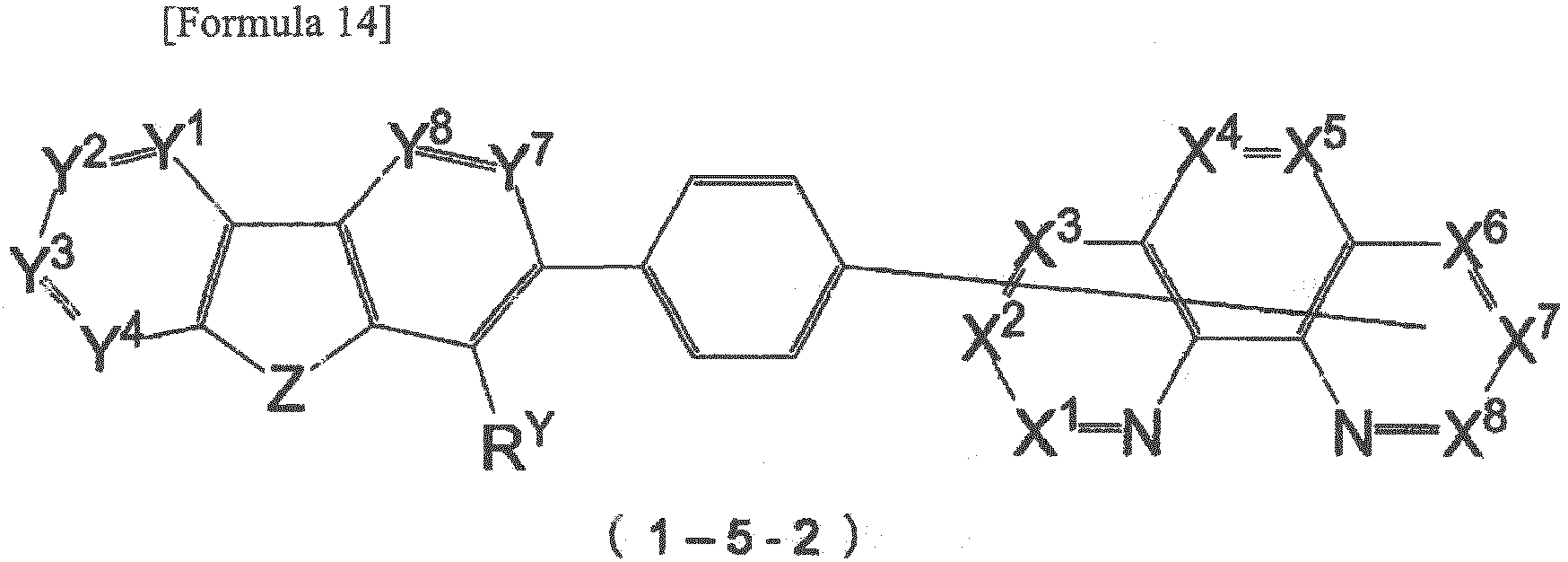
- When X1 or X8 of the formula (1) is a carbon atom to be bonded to the group represented by the formula (2) in which Z is a silicon atom, Y3 is a carbon atom to be bonded to L, L is a single bond, and RY of Y6 is bonded by a single bond to the phenanthrolyl group (the heteroaryl group having 5 to 40 ring atoms), RY of Y6 is bonded to the phenanthrolyl group at a position thereof other than a 2-position.
- In other words, when the compound represented by the formula (1) is represented by a formula (1-6) below, in the formula (2), Y3 is a carbon atom to be bonded to X1 or X8, Y6 is CRY in which RY is the phenanthrolyl group (the heteroaryl group having 5 to 40 ring atoms) which is shown on the left side of the formula (1-6) and one of X10 to X15 of the phenanthrolyl group is bonded to a carbon atom (C) of Y6. In the formula (1-6), the rest of X1 to X16 except for the carbon atom to be bonded to the group represented by the formula (2) are each independently CRX or a nitrogen atom. RX represents the same as RX in the formula (1). In the formula (1-6), Y1, Y2, Y4, Y5, Y7, Y8, R9 and R10 independently represent the same as Y1, Y2, Y4, Y5, Y7, Y8, R9 and R10 in the formula (2).

- In the formula (1), when X4 or X5 is a carbon atom to be bonded to the group represented by the formula (2) in which Y2 is a carbon atom to be bonded to L, L is a single bond and Z is an oxygen atom, RY in Y7 is a group other than a pyrenyl group.
- Alternatively, in the formula (1), when X4 or X5 is a carbon atom to be bonded to the group represented by the formula (2) in which Y7 is a carbon atom to be bonded to L, and L is a single bond and Z is an oxygen atom, RY in Y2 is a group other than a pyrenyl group.
- In other words, when the compound represented by the formula (1) is represented by a formula (1-xx-1) below, in the formula (2), Y2 is a carbon atom to be bonded to X1 or X8, Y7 is CRY. RY represents the same as RY described in the formula (2). It should be noted that RY is a group other than a pyrenyl group. In the formula (1-cx-1), Y1, Y4 to Y6, Y8 and X1 to X8 respectively represent the same as Y1, Y4 to Y6, Y8 and X1 to X8 in the formulae (1) and (2).
- Alternatively, when the compound represented by the formula (1) is represented by a formula (1-cx-1) below, in the formula (2), Y2 is a carbon atom to be bonded to X1 or X8, Y7 is CRY. RY represents the same as RY described in the formula (2). It should be noted that RY is a group other than a pyrenyl group. In the formula (1-cx-1), Y1, Y3 to Y4, Y5, Y8 and X1 to X8 respectively represent the same as Y1, Y3 to Y4, Y5, Y8 and X1 to X8 in the formulae (1) and (2).


- In the compound according to the exemplary embodiment, X1 or X8 in the formula (1) is preferably a carbon atom to be bonded to the group represented by the formula (2). Specifically, the compound according to the exemplary embodiment is preferably a compound represented by a formula (1-7) below.
- In the formula (1-7), Y1 to Y8, Z, L, b and c respectively represent the same as Y1 to Y8, Z, L, b and c in the formula (2). In the formula (1-7), X2 to X8 each independently represent CRX or a nitrogen atom in which RX represents the same as RX in the formula (1).

- Unlike in the compound represented by the formula (1-7), X8 instead of X1 may be a carbon atom to be bonded to the group represented by the formula (2).
- In the compound according to the exemplary embodiment, X1 and X8 in the formula (1) are preferably carbon atoms to be bonded to the group represented by the formula (2). Specifically, the compound according to the exemplary embodiment is preferably a compound represented by a formula (1-8) below.
- In the formula (1-8), X2 to X7 each independently represent CRX or a nitrogen atom in which RX represents the same as RX in the formula (1). In the formula (1-8), Y1 to Y16 each independently represent a nitrogen atom, CRY or a carbon atom to be bonded to L, in which RY represents the same as RY in the formula (2). In the formula (1-8), Z1 and Z2 each independently represent the same as Z in the formula (2). In the formula (1-8), L1 and L2 each independently represent the same as L in the formula (2). In the formula (1-8), b1 and b2 are each independently an integer of 1 to 5 and c1 and c2 are each independently an integer of 1 to 8.

- In the compound according to the exemplary embodiment, X3 and X6 in the formula (1) are preferably carbon atoms to be bonded to the group represented by the formula (2). Specifically, the compound according to the exemplary embodiment is preferably a compound represented by a formula (1-9) below.
- In the formula (1-9), X1, X2, X4, X5, X7 and X8 each independently represent CRX or a nitrogen atom in which RX represents the same as RX in the formula (1). In the formula (1-9), Y1 to Y16, Z1, Z2, L1, L2, b1, b2, c1 and c2 respectively represent the same as Y1 to Y16, Z1, Z2, L1, L2, b1, b2, c1 and c2 in the formula (1-8).

- In the compound according to the exemplary embodiment, X2 or X7 in the formula (1) is preferably a carbon atom to be bonded to the group represented by the formula (2). Specifically, the compound according to the exemplary embodiment is preferably a compound represented by a formula (1-10) below.
- In the formula (1-10), X1 and X3 to X8 each independently represent CRX or a nitrogen atom in which RX represents the same as RX in the formula (1). In the formula (1-10), Y1 to Y8, Z, L, b and c respectively represent the same as X1 to X8, Y1 to Y8, Z, L, b and c in the formula (2).

- Unlike in the compound represented by the formula (1-10), X7 instead of X2 may be a carbon atom to be bonded to the group represented by the formula (2).
- In the compound according to the exemplary embodiment, X3 or X6 in the formula (1) is preferably a carbon atom to be bonded to the group represented by the formula (2). Specifically, the compound according to the exemplary embodiment is preferably a compound represented by a formula (1-11) below.
- In the formula (1-11), X1, X2 and X4 to X8 each independently represent CRX or a nitrogen atom in which RX represents the same as RX in the formula (1). In the formula (1-11), Y1 to Y8, Z, L, b and c respectively represent the same as Y1 to Y8, Z, L, b and c in the formula (2).

- Unlike in the compound represented by the formula (1-11), X6 instead of X3 may be a carbon atom to be bonded to the group represented by the formula (2).
- In the compound according to the exemplary embodiment, X4 or X5 in the formula (1) is preferably a carbon atom to be bonded to the group represented by the formula (2). Specifically, the compound according to the exemplary embodiment is preferably a compound represented by a formula (1-12) below.
- In the formula (1-12), X1 to X3 and X5 to X8 each independently represent CRX or a nitrogen atom in which RX represents the same as RX in the formula (1). In the formula (1-12), Y1 to Y8, Z, L, b and c respectively represent the same as Y1 to Y8, Z, L, b and c in the formula (2).

- Unlike in the compound represented by the formula (1-12), X5 instead of X4 may be a carbon atom to be bonded to the group represented by the formula (2).
- In the compound according to the exemplary embodiment, X1 and X7 in the formula (1) are preferably carbon atoms to be bonded to the group represented by the formula (2). Specifically, the compound according to the exemplary embodiment is preferably a compound represented by a formula (1-13) below.
- In the formula (1-13), X2 to X6 and X8 each independently represent CRX or a nitrogen atom in which RX represents the same as RX in the formula (1). In the formula (1-13), Y1 to Y16, Z1, Z2, L1, L2, b1, b2, c1 and c2 respectively represent the same as Y1 to Y16, Z1, Z2, L1, L2, b1, b2, c1 and c2 in the formula (1-8).

- In the compound according to the exemplary embodiment, X2 and X7 in the formula (1) are preferably carbon atoms to be bonded to the group represented by the formula (2). Specifically, the compound according to the exemplary embodiment is preferably a compound represented by a formula (1-14) below.
- In the formula (1-14), X1, X3 to X6 and X8 each independently represent CRX or a nitrogen atom in which RX represents the same as RX in the formula (1). In the formula (1-14), Y1 to Y16, Z1, Z2, L1, L2, b1, b2, c1 and c2 respectively represent the same as Y1 to Y16, Z1, Z2, L1, L2, b1, b2, c1 and c2 in the formula (1-8).

- In the compound according to the exemplary embodiment, X1, X2, X7 and X8 in the formula (1) are preferably carbon atoms to be bonded to the group represented by the formula (2). Specifically, the compound according to the exemplary embodiment is preferably a compound represented by a formula (1-15) below.
- In the formula (1-15), X3 to X6 each independently represent CRX or a nitrogen atom in which RX represents the same as RX in the formula (1). In the formula (1-15), Y1 to Y32 each independently represent a nitrogen atom, CRY or a carbon atom to be bonded to L, in which RY represents the same as RY in the formula (2). In the formula (1-15), Z1 to Z4 each independently represent the same as Z in the formula (2). In the formula (1-15), L1 to L4 each independently represent the same as L in the formula (2). In the formula (1-15), b1 to b4 are each independently an integer of 1 to 5 and c1 to c2 are each independently an integer of 1 to 8.


- In the compound according to the exemplary embodiment, X1, X3, X6 and X8 in the formula (1) are preferably carbon atoms to be bonded to the group represented by the formula (2). Specifically, the compound according to the exemplary embodiment is preferably a compound represented by a formula (1-16) below.
- In the formula (1-16), X2, X4, X5 and X7 each independently represent CRX or a nitrogen atom in which RX represents the same as RX in the formula (1). In the formula (1-16), Y1 to Y32 each independently represent a nitrogen atom, CRY or a carbon atom to be bonded to L, in which RY represents the same as RY in the formula (2). In the formula (1-16), Z1 to Z4 each independently represent the same as Z in the formula (2). In the formula (1-16), L1 to L4 each independently represent the same as L in the formula (2). In the formula (1-16), b1 to b4 are each independently an integer of 1 to 5 and c1 to c2 are each independently an integer of 1 to 8.


- In the compound according to the exemplary embodiment, the formula (2) is preferably represented by a formula (2-2). At least one of X1 to X8 is preferably a carbon atom to be bonded to the group represented by the formula (2-2).

- In the formula (2-2), b1 and b2 are each independently an integer of 1 to 5.
- c1, c2 and c3 are each independently an integer of 0 to 7 and c1+c2+c3 is an integer of 7 or less.
- Z represents an oxygen atom, sulfur atom or silicon atom. When b is from 2 to 5, a plurality of Z are mutually the same or different. When Z is a silicon atom, R9 and R10 are bonded to the silicon atom. R9 and R10 each independently represent the same as RX in the formula (10). R9 and R10 may be bonded to the structure represented by the formula (10).
- L1 represents a linking group. The linking group is a substituted or unsubstituted polyvalent linear, branched or cyclic aliphatic hydrocarbon group having 1 to 30 carbon atoms, a substituted or unsubstituted polyvalent aryl group having 6 to 40 ring carbon atoms, or a substituted or unsubstituted polyvalent heteroaryl group having 5 to 40 ring atoms.
- L2, L3 and L4 are each independently selected from a single bond and a linking group. The linking group is a substituted or unsubstituted polyvalent linear, branched or cyclic aliphatic hydrocarbon group having 1 to 30 carbon atoms, a substituted or unsubstituted polyvalent aryl group having 6 to 40 ring carbon atoms, or a substituted or unsubstituted polyvalent heteroaryl group having 5 to 40 ring atoms.
- The polyvalent heteroaryl group having 5 to 40 ring atoms in L1 to L4 of the formula (2-2) also includes a substituted or unsubstituted polyvalent group derived from a phenanthroline ring represented by the formula (10). When c1 is an integer of 2 or more, a plurality of L2 are mutually the same or different. When c2 is an integer of 2 or more, a plurality of L3 are mutually the same or different. When c3 is an integer of 2 or more, a plurality of L4 are mutually the same or different.
- Y1 to Y8 each independently represent a nitrogen atom, CRY or a carbon atom to be bonded to L3.
- Y9 to Y16 each independently represent a nitrogen atom, CRZ or a carbon atom to be bonded to L4.
- RY and RZ each independently represent the same as RX in the formula (10). The heteroaryl group having 5 to 40 ring atoms in RY and RZ includes a substituted or unsubstituted phenanthrolyl group derived from the phenanthroline ring represented by the formula (10). Adjacent ones of RY may be bonded to each other to form a cyclic structure or may not be bonded.
- In the exemplary embodiment, X1 or X8 is preferably a carbon atom to be bonded to the group represented by the formula (2-2).
- In the exemplary embodiment, L1 in the formula (2-2) is preferably a substituted or unsubstituted polyvalent aryl group having 6 to 40 ring carbon atoms, more preferably a substituted or unsubstituted polyvalent aryl group having 6 ring carbon atoms.
- In the exemplary embodiment, L2 in the formula (2-2) is preferably a substituted or unsubstituted polyvalent heteroaryl group having 5 to 40 ring atoms. In the the formula (2-2), L2 directly bonded to L1 is preferably a substituted or unsubstituted polyvalent heteroaryl group having 5 to 40 ring atoms.
- In the exemplary embodiment, it is preferable that, in the formula (2-2), c1 is 2 or more and a plurality of L2 include a substituted or unsubstituted polyvalent heteroaryl group having 5 to 40 ring atoms and a substituted or unsubstituted polyvalent aryl group having 6 to 40 ring carbon atoms. In this arrangement, in the formula (2-2), L2 directly bonded to L1 is preferably a substituted or unsubstituted polyvalent heteroaryl group having 5 to 40 ring atoms.
- In the exemplary embodiment, L3 and L4 in the formula (2-2) are preferably each independently a single bond or a substituted or unsubstituted polyvalent aryl group having 6 to 40 ring carbon atoms, more preferably a substituted or unsubstituted polyvalent aryl group having 6 ring carbon atoms.
- In the exemplary embodiment, c2 and c3 are each preferably 1. In this arrangement, L3 and L4 are each preferably a substituted or unsubstituted polyvalent aryl group having 6 to 40 ring carbon atoms, more preferably a single bond or a substituted or unsubstituted polyvalent aryl group having 6 ring carbon atoms.
- In the compounds represented by the formulae (1-7) to (1-16), the compounds represented by the formulae (1-7) and (1-8) are preferable.
- Moreover, the compound represented by the formula (1-1) is preferable.
- In the compound according to the exemplary embodiment, Z and Z1 to Z4 in the formulae (2), (2-1), (1-1) to (1-3), (1-5), (1-7) to (1-16) are each preferably an oxygen atom or a sulfur atom, more preferably an oxygen atom.
- In the formulae (1), (1-1) to (1-16), (2-1), (1-x), (1-cx-1) and (1-xx-2), the rest of X1 to X16 except for the carbon atom to be bonded to the group represented by the formula (2) are preferably CRX, in which RX is preferably a hydrogen atom, alkyl group or aryl group, further preferably a hydrogen atom or a phenyl group.
- Next, each of the substituents described in the formulae (1), (1-1) to (1-16), (2), (2-1), (1-x), (1-xx-1) and (1-xx-2) will be described below. Examples of the substituents described in the formulae (1), (1-1) to (1-16), (2), (2-1), (1-x), (1-xx-1) and (1-xx-2) include a hydrogen atom, halogen atom, cyano group, nitro group, substituted or unsubstituted hydroxyl group, substituted or unsubstituted carboxyl group, substituted or unsubstituted sulfonyl group, substituted or unsubstituted boryl group, substituted or unsubstituted phosphino group, substituted or unsubstituted mercapto group, substituted or unsubstituted acyl group, substituted or unsubstituted amino group, substituted or unsubstituted silyl group, substituted or unsubstituted alkyl group having 1 to 30 carbon atoms, substituted or unsubstituted alkenyl group having 2 to 30 carbon atoms, substituted or unsubstituted alkynyl group having 2 to 30 carbon atoms, substituted or unsubstituted aralkyl group having 6 to 30 carbon atoms, substituted or unsubstituted aryl group having 6 to 40 ring carbon atoms, and substituted or unsubstituted heteroaryl group having 5 to 40 ring atoms.
- Examples of the halogen atom in the formulae (1), (1-1) to (1-16), (2), (2-1), (1-x), (1-xx-1) and (1-xx-2) include fluorine, chlorine, bromide, and iodine, among which a fluorine atom is preferable.
- Examples of the substituted or unsubstituted hydroxyl group in the formulae (1), (1-1) to (1-16), (2), (2-1), (1-x), (1-xx-1) and (1-xx-2) include a hydroxyl group (-OH) and a group represented by -ORA that is obtained by substituting H of a hydroxyl group (-OH) with RA.
- Herein, when RA is an alkyl group, the group represented by -ORA is an alkoxy group, preferably a substituted or unsubstituted alkoxy group having 1 to 30 carbon atoms. The alkyl group as RA is preferably an alkyl group having 1 to 30 carbon atoms below. Examples of the alkoxy group include a methoxy group, ethoxy group, propoxy group, butoxy group, pentyloxy group and hexyloxy group. Among the alkoxy group, an alkoxy group having 1 to 10 carbon atoms is preferable and an alkoxy group having 1 to 8 carbon atoms is more preferable. An alkoxy group having 1 to 4 carbon atoms is particularly preferable.
- Here, examples of the substituted or unsubstituted alkoxy group include a haloalkoxy group that is obtained by substituting an alkyl group (RA) with one or more halogen atoms described above.
- Moreover, when RA is an aryl group, the group represented by -ORA is an aryloxy group, preferably a substituted or unsubstituted aryloxy group having 6 to 40 ring carbon atoms. The aryl group as RA is preferably an aryl group having 6 to 40 ring carbon atoms below. The aryloxy group is exemplified by a phenoxy group.
- Here, examples of the substituted or unsubstituted aryloxy group include a haloaryloxy group that is obtained by substituting an aryl group (RA) with one or more halogen atoms described above.
- Moreover, when RA is a heteroaryl group, the group represented by -ORA is a heteroaryloxy group, preferably a substituted or unsubstituted heteroaryloxy group having 5 to 40 ring atoms. The heteroaryl group as RA is preferably a heteroaryl group having 5 to 40 ring atoms below.
- Examples of the substituted or unsubstituted carboxyl group in the formulae (1), (1-1) to (1-16), (2), (2-1), (1-x), (1-xx-1) and (1-xx-2) include a carboxyl group (-COOH) and a group represented by -COORB that is obtained by substituting H of a carboxyl group (-COOH) with RB.
- Herein, when RB is an alkyl group, the group represented by-COORB is an alkoxycarbonyl group, preferably a substituted or unsubstituted alkoxycarbonyl group having 2 to 30 carbon atoms. The alkyl group as RB is preferably an alkyl group having 1 to 30 carbon atoms below.
- Moreover, when RB is an aryl group, the group represented by-COORB is an aryloxycarbonyl group, preferably a substituted or unsubstituted aryloxycarbonyl group having 7 to 40 carbon atoms. The aryl group as RB is preferably an aryl group having 6 to 40 ring carbon atoms below.
- Moreover, when RB is a heteroaryl group, the group represented by-COORB is a heteroarylcarbonyl group, preferably a substituted or unsubstituted heteroarylcarbonyl group having 5 to 40 ring atoms. The heteroaryl group as RB is preferably a heteroaryl group having 5 to 40 ring atoms below.
- Examples of the substituted or unsubstituted boryl group in the formulae (1), (1-1) to (1-16), (2), (2-1), (1-x), (1-xx-1) and (1-xx-2) include a boryl group (-BH2) and a group represented by -BRERE that is obtained by substituting H of a boryl group (-BH2) with RE,RE.
- Herein, when RE is an alkyl group, the group represented by -BRERE is an alkylboryl group, preferably a substituted or unsubstituted alkylboryl. The alkyl group as RE is preferably an alkyl group having 1 to 30 carbon atoms below.
- When RE is an aryl group, the group represented by -BRERE is an arylboryl group, preferably a substituted or unsubstituted arylboryl. The aryl group as RE is preferably an aryl group having 6 to 40 ring carbon atoms below.
- When RE is a heteroaryl group, the group represented by -BRERE is a heteroarylboryl group, preferably a substituted or unsubstituted heteroarylboryl. The heteroaryl group as RE is preferably a heteroaryl group having 5 to 40 ring atoms below.
- In addition, a dihydroxyboryl group (-B(OH)2) is also usable.
- Examples of the substituted or unsubstituted phosphino group in the formulae (1), (1-1) to (1-16), (2), (2-1), (1-x), (1-cx-1) and (1-xx-2) include a phosphino group (-PH2), a group represented by -PRFRF that is obtained by substituting H of a phosphino group (-PH2) with RF,RF, and a group represrented by -P(O)RFRF.
- Herein, when RF is an alkyl group, the group represented by -PRFRF is an alkylphosphino group, preferably a substituted or unsubstituted alkylphosphino. The alkyl group as RF is preferably an alkyl group having 1 to 30 carbon atoms below.
- When RF is an aryl group, the group represented by -PRFRF is an arylphosphino group, preferably a substituted or unsubstituted arylphosphino. The aryl group as RF is preferably an aryl group having 6 to 40 ring carbon atoms below.
- When RF is a heteroaryl group, the group represented by -PRFRF is a heteroarylphosphino group, preferably a substituted or unsubstituted heteroarylphosphino. The heteroaryl group as RF is preferably a heteroaryl group having 5 to 40 ring atoms below.
- Examples of the substituted or unsubstituted mercapto group in the formulae (1), (1-1) to (1-16), (2), (2-1), (1-x), (1-cx-1) and (1-xx-2) include a mercapto group (-SH) and a group represented by -SRC that is obtained by substituting H of a mercapto group (-SH) with RC. Herein, when RC is an alkyl group, the group represented by -SRC is an alkylthio group, preferably a substituted or unsubstituted alkylthio group having 1 to 30 carbon atoms. The alkyl group as RC is preferably an alkyl group having 1 to 30 carbon atoms below. Moreover, when RC is an aryl group, the group represented by -SRC is an arylthio group, preferably a substituted or unsubstituted arylthio group having 6 to 40 ring carbon atoms. The aryl group as RC is preferably an aryl group having 6 to 40 ring carbon atoms below. Moreover, when RC is a heteroaryl group, the group represented by -SRC is a heteroarylthio group, preferably a substituted or unsubstituted heteroarylthio group having 5 to 40 ring atoms. The heteroaryl group as RC is preferably a heteroaryl group having 5 to 40 ring atoms below.
- The substituted or unsubstituted acyl group in the formulae (1), (1-1) to (1-16), (2), (2-1), (1-x), (1-xx-1) and (1-xx-2) is represented by -CO-RD.
- Herein, when RD is an alkyl group, the acyl group is an alkylcarbonyl group, preferably a substituted or unsubstituted alkylcarbonyl group having 2 to 30 carbon atoms. The alkyl group as RD is preferably an alkyl group having 1 to 30 carbon atoms below. Examples of the alkylcarbonyl group include an acetyl group, propionyl group, butyryl group, valeryl group, pivaloyl group, palmitoyl group, stearoyl group and oleoyl group.
- Moreover, when RD is an aryl group, the acyl group is an arylcarbonyl group (also referred to as an aroyl group), preferably a substituted or unsubstituted arylcarbonyl group having 6 to 40 ring carbon atoms. The aryl group as RD is preferably an aryl group having 6 to 40 ring carbon atoms below. Examples of the arylcarbonyl group include a benzoyl group, toluoyl group, salicyloyl group, cinnamoyl group, naphthoyl group and phthaloyl group.
- Moreover, when RD is a heteroaryl group, the represented by -CO-RD is a heteroarylcarbonyl group, preferably a substituted or unsubstituted heteroarylcarbonyl group having 5 to 40 ring atoms. The heteroaryl group as RD is preferably a heteroaryl group having 5 to 40 ring atoms below. Examples of the heteroarylcarbonyl group include a furoyl group, pyrrolylcarbonyl group, pyridylcarbonyl group and thienylcarbonyl group.
- It should be noted that a formyl group (-CO-H) in which RD is substituted with a hydrogen atom is included in the examples of the acyl group.
- Examples of the substituted or unsubstituted amino group in the formulae (1), (1-1) to (1-16), (2), (2-1), (1-x), (1-xx-1) and (1-xx-2) include an amino group (-NH2) and an amino group in which H of an amino group (-NH2) are substituted with substituents. Examples of the substituted amino group include an alkylamino group substituted with a substituted or unsubstituted alkyl having 1 to 30 carbon atoms, an arylamino group substituted with a substituted or unsubstituted aryl group having 6 to 40 ring carbon atoms, a heteroarylamino group substituted with a substituted or unsubstituted heteroaryl group having 5 to 40 ring atoms, and an acylamino group substituted with a substituted or unsubstituted acyl group having 2 to 30 carbon atoms.
- The alkyl group having 1 to 30 carbon atoms in the alkylamino group is preferably an alkyl group having 1 to 30 carbon atoms listed below. When the amino group is substituted with two alkyl groups, the two alkyl groups may be mutually the same or different.
- The aryl group having 6 to 40 ring carbon atoms in the arylamino group is preferably an aryl group having 6 to 40 ring carbon atoms. The arylamino group is preferably an amino group substituted with a phenyl group. When the amino group is substituted with two aryl groups, the two aryl groups may be mutually the same or different.
- The heteroaryl group having 5 to 40 ring atoms in the heteroarylamino group is preferably a heteroaryl group having 5 to 40 ring atoms below. When the amino group is substituted with two heteroaryl groups, the two heteroaryl groups may be mutually the same or different.
- The acyl group having 2 to 30 carbon atoms in the acylamino group is preferably selected from the above acyl group.
- The substituted amino group may be an amino group substituted with two selected from a hydrogen atom, alkyl group, aryl group, heteroaryl group and acyl group.
- The substituted amino group may be an amino group substituted with an alkyl group and an aryl group. Examples of the substituted amino group include an alkylarylamino group, alkylheteroarylamino group, arylheteroarylamino group, alkylacylamino group and arylacylamino group.
- Examples of the substituted or unsubstituted silyl group in the formulae (1), (1-1) to (1-16), (2), (2-1), (1-x), (1-xx-1) and (1-xx-2) include an unsubstituted silyl group, an alkylsilyl group substituted with a substituted or unsubstituted alkyl group having 1 to 30 carbon atoms, an arylsilyl group substituted with a substituted or unsubstituted aryl group having 6 to 40 ring carbon atoms, and a heteroarylsilyl group substituted with a substituted or unsubstituted heteroaryl group having 5 to 40 ring atoms.
- The alkylsilyl group is exemplified by a trialkylsilyl group having the above alkyl group having 1 to 30 carbon atoms. Specific examples of the trialkylsilyl group include a trimethylsilyl group, triethylsilyl group, tri-n-butylsilyl group, tri-n-octylsilyl group, triisobutylsilyl group, dimethylethylsilyl group, dimethylisopropylsilyl group, dimethyl-n-propylsilyl group, dimethyl-n-butylsilyl group, dimethyl-t-butylsilyl group, diethylisopropylsilyl group, vinyldimethylsilyl group, propyldimethylsilyl group and triisopropylsilyl group. Three alkyl groups in the trialkylsilyl group may be mutually the same or different.
- The arylsilyl group is exemplified by a triarylsilyl group including three of an aryl group having 6 to 40 ring carbon atoms below. The triarylsilyl group preferably has 18 to 30 carbon atoms. The three aryl groups may be mutually the same or different.
- The heteroarylsilyl group is exemplified by a triheteroarylsilyl group having three of a heteroaryl group having 5 to 40 ring atoms below. The three heteroaryl groups may be mutually the same or different.
- The substituted silyl group may be a silyl group substituted with at least two groups selected from an alkyl group, aryl group and heteroaryl group.
- The substituted silyl group may be a silyl group substituted with an alkyl group and an aryl group. Examples of the substituted silyl group include an alkylarylsilyl group, dialkylarylsilyl group, diarylsilyl group, alkkyldiarylsilyl group and triarlysilyl group. A plurality of aryl groups or alkyl groups may be mutually the same or different.
- The dialkylarylsilyl group is exemplified by a dialkylarylsilyl group including two of the alkyl group listed as the examples of the alkyl group having 1 to 30 carbon atoms and one of the aryl group listed as the examples of the aryl group having 6 to 40 ring carbon atoms. The dialkylarylsilyl group preferably has 8 to 30 carbon atoms. The two alkyl groups may be mutually the same or different.
- The alkyldiarylsilyl group is exemplified by an alkyldiarylsilyl group including one of the alkyl group listed as the examples of the alkyl group having 1 to 30 carbon atoms and two of the aryl group listed as the examples of the aryl group having 6 to 40 ring carbon atoms. The alkyldiarylsilyl group preferably has 13 to 30 carbon atoms. The two aryl groups may be mutually the same or different.
- Examples of the above arylsilyl group are a phenyldimethylsilyl group, a diphenylmethylsilyl group, a diphenyl-t-butylsilyl group and a triphenylsilyl group.
- The substituted silyl group may be a silyl group substituted with an alkyl group and a heteroaryl group, a silyl group substituted with an aryl group and a heteroaryl group, and a silyl group substituted with an alkyl group, aryl group and heteroaryl group.
- The alkyl group having 1 to 30 carbon atoms in the formulae (1), (1-1) to (1-16), (2), (2-1), (1-x), (1-xx-1) and (1-xx-2) may be linear, branched or cyclic. Examples of the substituted alkyl group having 1 to 30 carbon atoms include a haloalkyl group. The haloalkyl group is exemplified by a haloalkyl group obtained by substituting the alkyl group having 1 to 30 carbon atoms with one or more halogen atoms. Examples of the substituted or unsubstituted linear or branched alkyl group are a methyl group, ethyl group, propyl group, isopropyl group, n-butyl group, s-butyl group, isobutyl group, t-butyl group, n-pentyl group, n-hexyl group, n-heptyl group, n-octyl group, n-nonyl group, n-decyl group, n-undecyl group, n-dodecyl group, n-tridecyl group, n-tetradecyl group, n-pentadecyl group, n-hexadecyl group, n-heptadecyl group, n-octadecyl group, neopentyl group, 1-methylpentyl group, 2-methylpentyl group, 1-pentylhexyl group, 1-butylpentyl group, 1-heptyloctyl group, 3-methylpentyl group, hydroxymethyl group, 1-hydroxyethyl group, 2-hydroxyethyl group, 2-hydroxyisobutyl group, 1,2-dihydroxyethyl group, 1,3-dihydroxyisopropyl group, 2,3-dihydroxy-t-butyl group, 1,2,3-trihydroxypropyl group, chloromethyl group, 1-chloroethyl group, 2-chloroethyl group, 2-chloroisobutyl group, 1,2-dichloroethyl group, 1,3-dichloroisopropyl group, 2,3-dichloro-t-butyl group, 1,2,3-trichloropropyl group, bromomethyl group, 1-bromoethyl group, 2-bromoethyl group, 2-bromoisobutyl group, 1,2-dibromoethyl group, 1,3-dibromoisopropyl group, 2,3-dibromo-t-butyl group, 1,2,3-tribromopropyl group, iodomethyl group, 1-iodoethyl group, 2-iodoethyl group, 2-iodoisobutyl group, 1,2-diiodoethyl group, 1,3-diiodoisopropyl group, 2,3-diiodo-t-butyl group, 1,2,3-triiodopropyl group, aminomethyl group, 1-aminoethyl group, 2-aminoethyl group, 2-aminoisobutyl group, 1,2-diaminoethyl group, 1,3-diaminoisopropyl group, 2,3-diamino-t-butyl group, 1,2,3-triaminopropyl group, cyanomethyl group, 1-cyanoethyl group, 2-cyanoethyl group, 2-cyanoisobutyl group, 1,2-dicyanoethyl group, 1,3-dicyanoisopropyl group, 2,3-dicyano-t-butyl group, 1,2,3-tricyanopropyl group, nitromethyl group, 1-nitroethyl group, 2-nitroethyl group, 1,2-dinitroethyl group, 2,3-dinitro-t-butyl group, 1,2,3-trinitropropyl group, fluoromethyl group, difluoromethyl group, trifluoromethyl group, fluoroethyl group, 2,2,2-trifluoroethyl group and 1,1,1,3,3,3-hexafluoro-2-propyl group.
- The substituted or unsubstituted cyclic alkyl group (cycloalkyl group) is preferably a substituted or unsubstituted cycloalkyl group having 3 to 30 carbon atoms. Examples of the cycloalkyl group include a cyclopropyl group, cyclobutyl group, cyclopentyl group, cyclohexyl group, cyclooctyl group, 4-methylcyclohexyl group, 3,5-tetramethylcyclohexyl group, 1-adamantyl group, 2-adamantyl group, 1-norbornyl group and 2-norbornyl group.
- Among the above alkyl group, an alkyl group having 1 to 10 carbon atoms is preferable. An alkyl group having 1 to 8 carbon atoms is more preferable. An alkyl group having 1 to 6 carbon atoms is particularly preferable. Among the above alkyl group, a methyl group, isopropyl group, t-butyl group and cyclohexyl group are preferable.
- The substituted or unsubstituted alkenyl group having 2 to 30 carbon atoms in the formulae (1), (1-1) to (1-16), (2), (2-1), (1-x), (1-xx-1) and (1-xx-2) may be linear, branched or cyclic. Examples of the alkenyl group are a vinyl group, propenyl group, butenyl group, oleyl group, eicosapentaenyl group, docosahexaenyl group, styryl group, 2,2-diphenylvinyl group, 1,2,2-triphenylvinyl group and 2-phenyl-2-propenyl group. Among the above alkenyl group, a vinyl group is preferable.
- Examples of the substituted or unsubstituted alkynyl group having 2 to 30 carbon atoms in the formulae (1), (1-1) to (1-16), (2), (2-1), (1-x), (1-xx-1) and (1-xx-2) include an ethynyl group, propynyl group and and 2-phenylethynyl group. Among the above alkynyl group, an ethynyl group is preferable.
- The aralkyl group having 7 to 40 carbon atoms in the formulae (1), (1-1) to (1-16), (2), (2-1), (1-x), (1-xx-1) and (1-xx-2) is represented by -RE-RF. RE is exemplified by an alkylene group provided as a divalent group derived from the alkyl group having 1 to 30 carbon atoms described below. RF is exemplified by the examples of an aryl group having 6 to 40 ring carbon atoms below. In the aralkyl group, an aryl group moiety has 6 to 40 carbon atoms, preferably 6 to 20 carbon atoms, more preferably 6 to 12 carbon atoms. In the aralkyl group, an alkyl group moiety has 1 to 30 carbon atoms, preferably 1 to 20 carbon atoms, more preferably 1 to 10 carbon atoms, further preferably 1 to 6 carbon atoms. Examples of the aralkyl group are a benzyl group, 2-phenylpropane-2-yl group, 1-phenylethyl group, 2-phenylethyl group, 1-phenylisopropyl group, 2-phenylisopropyl group, phenyl-t-butyl group, α-naphthylmethyl group, 1-α-naphthylethyl group, 2-α-naphthylethyl group, 1-α-naphthylisopropyl group, 2-α-naphthylisopropyl group, β-naphthylmethyl group, 1-β-naphthylethyl group, 2-β-naphthylethyl group, 1-β-naphthylisopropyl group, 2-β-naphthylisopropyl group, 1-pyrorylmethyl group, 2-(1-pyroryl)ethyl group, p-methylbenzyl group, m-methylbenzyl group, o-methylbenzyl group, p-chlorobenzyl group, m-chlorobenzyl group, o-chlorobenzyl group, p-bromobenzyl group, m-bromobenzyl group, o-bromobenzyl group, p-iodobenzyl group, m-iodobenzyl group, o-iodobenzyl group, p-hydroxybenzyl group, m-hydroxybenzyl group, o-hydroxybenzyl group, p-aminobenzyl group, m-aminobenzyl group, o-aminobenzyl group, p-nitrobenzyl group, m-nitrobenzyl group, o-nitrobenzyl group, p-cyanobenzyl group, m-cyanobenzyl group, o-cyanobenzyl group, 1-hydroxy-2-phenylisopropyl group and 1-chloro-2-phenylisopropyl group.
- Examples of the aryl group having 6 to 40 ring carbon atoms in the formulae (1), (1-1) to (1-16), (2), (2-1), (1-x), (1-xx-1) and (1-xx-2) include a non-fused aryl group and a fused aryl group. Specific examples of the aryl group include a phenyl group, naphthyl group, anthryl group, phenanthryl group, biphenyl group, terphenyl group, quaterphenyl group, fluoranthenyl group, pyrenyl group, triphenylenyl group, phenanthrenyl group, fluorenyl group, 9,9-dimethylfluorenyl group, spirofluorenyl group, benzo[c]phenanthrenyl group, benzo[a]triphenylenyl group, naphtho[1,2-c]phenanthrenyl group, naphtho[1,2-a]triphenylenyl group, dibenzo[a,c]triphenylenyl group and benzo[b]fluoranthenyl group. Among the above aryl group, an aryl group having 6 to 30 ring carbon atoms is preferable. An aryl group having 6 to 20 ring carbon atoms is more preferable. An aryl group having 6 to 12 ring carbon atoms is particularly preferable.
- Moreover, since a high triplet energy level is desired in use for an electron transporting material, an aryl group having triplet energy T1 exceeding 2.1 eV is preferable. Examples of the aryl group include a phenyl group, naphthyl group, phenanthryl group, biphenyl group, terphenyl group, quaterphenyl group, fluoranthenyl group, triphenylenyl group, phenanthrenyl group, fluorenyl group, 9,9-dimethylfluorenyl group, spirofluorenyl group, benzo[c]phenanthrenyl group, benzo[a]triphenylenyl group, naphtho[1,2-c]phenanthrenyl group, naphtho[1,2-a]triphenylenyl group, dibenzo[a,c]triphenylenyl group and benzo[b]fluoranthenyl group.
- Examples of the heteroaryl group having 5 to 40 ring atoms in the formulae (1), (1-1) to (1-16), (2), (2-1), (1-x), (1-xx-1) and (1-xx-2) include a non-fused heteroaryl group and a fused heteroaryl group. Specific examples of the heteroaryl group include a pyroryl group, pyrazinyl group, pyridinyl group, indolyl group, isoindolyl group, furyl group, benzofuranyl group, isobenzofuranyl group, dibenzofuranyl group, dibenzothiophenyl group, quinolyl group, isoquinolyl group, quinoxalinyl group, carbazolyl group, phenanthrydinyl group, acridinyl group, phenanthrolinyl group, thienyl group, and group derived from a pyridine ring, pyrazine ring, pyrimidine ring, pyridazine ring, triazine ring, indole ring, quinoline ring, acridine ring, pyrrolidine ring, dioxane ring, piperidine ring, morpholine ring, piperazine ring, carbazole ring, furan ring, thiophene ring, oxazole ring, oxadiazole ring, benzoxazole ring, thiazole ring, thiadiazole ring, benzothiazole ring, triazole ring, imidazole ring, benzimidazole ring, pyrane ring, dibenzofuran ring, benzo[c]dibenzofuran ring and silafluorene ring. Among the above heteroaryl group, a heteroaryl group having 5 to 40 ring atoms is preferable. A heteroaryl group having 5 to 20 ring atoms is more preferable. A heteroaryl group having 5 to 12 ring atoms is particularly preferable.
- Examples of the polyvalent linear, branched or cyclic aliphatic hydrocarbon group when L and L1 to L12 are the linking groups in the formulae (1), (1-1) to (1-16), (2), (2-1), (1-x), (1-xx-1) and (1-xx-2) include: a polyvalent group derived from the polyvalent linear, branched or cyclic alkyl group having 1 to 30 carbon atoms; a polyvalent group derived from the polyvalent linear, branched or cyclic alkenyl group having 1 to 30 carbon atoms; and a polyvalent group derived from the polyvalent linear, branched or cyclic alkynyl group having 1 to 30 carbon atoms, among which a divalent or trivalent group is preferable and a divalent group is more preferable. The divalent group may be substituted with the above-described substituents. Specific examples of the divalent group include a methylene group, ethylene group, acethylenylene and vinylidene group.
- Examples of the polyvalent aryl group having 6 to 40 ring carbon atoms when L and L1 to L12 are the linking groups in the formulae (1), (1-1) to (1-16), (2), (2-1), (1-x), (1-xx-1) and (1-xx-2) include a polyvalent group derived from the aryl group having 6 to 40 ring carbon atoms, among which a divalent or trivalent group is preferable and a divalent group is more preferable. Specifically, a divalent group derived from a phenyl group, biphenyl group, naphthyl group and 9,9-dimethylfluorenyl group is preferable. The divalent group may be subsitutued with the above-described substituents.
- Examples of the polyvalent heteroaryl group having 5 to 40 ring atoms when L and L1 to L12 are the linking groups in the formulae (1), (1-1) to (1-16), (2), (2-1), (1-x),
- (1-xx-1) and (1-xx-2) include a polyvalent group derived from the heteroaryl group having 5 to 40 ring atoms, among which a divalent or trivalent group is preferable and a divalent group is more preferable. Specifically, a divalent group derived from a pyridyl group, pyrimidyl group, dibenzofuranyl group, silafluorenyl group and carbazolyl group is preferable. The divalent group may be subsitutued with the above-described substituents.
- In the formulae (1), (1-1) to (1-16), (2), (2-1), (1-x), (1-xx-1) and (1-xx-2), the rest of Y1 to Y16 except for the carbon atom to be bonded to L and L1 to L12 are preferably CRY, in which RY is preferably a hydrogen atom or alkyl group, particularly preferably a hydrogen atom.
- In the invention, "carbon atoms forming a ring (ring carbon atoms)" mean carbon atoms forming a saturated ring, an unsaturated ring, or an aromatic ring. "Atoms forming a ring (ring atoms)" mean carbon atoms and hetero atoms forming a hetero ring including a saturated ring, unsaturated ring, or aromatic ring.
- In the invention, a hydrogen atom includes isotope having different numbers of neutrons, specifically, protium, deuterium and tritium.
- Examples of the substituent meant by "substituted or unsubstituted" are the above-described aryl group, heteroaryl group, alkyl group (linear or branched alkyl group, cycloalkyl group and haloalkyl group), alkoxy group, aryloxy group, aralkyl group, haloalkoxy group, alkylsilyl group, dialkylarylsilyl group, alkyldiarylsilyl group, triarylsilyl group, halogen atom, cyano group, hydroxyl group, nitro group and carboxy group. In addition, the alkenyl group and alkynyl group are also usable.
- Among the above substituents, an aryl group, heteroaryl group, alkyl group, halogen atom, alkylsilyl group, arylsilyl group and cyano group are preferable. More preferable substituents are one listed as the preferable substituents described for each substituent.
- "Unsubstituted" in "substituted or unsubstituted" means that a group is not substituted by the above-described substituents but bonded with a hydrogen atom.
- Herein, "a to b carbon atoms" in the description of "substituted or unsubstituted XX group having a to b carbon atoms" represent carbon atoms of an unsubstituted XX group and does not include carbon atoms of a substituted XX group.
- The same description as the above applies to "substituted or unsubstituted" in the following compound or a partial structure thereof.
- Specific examples of the compound represented by the formula (1) are shown below, but the invention is not limited to thereto.
- Examples of the compound represented by the formula (1-7) are as follows.


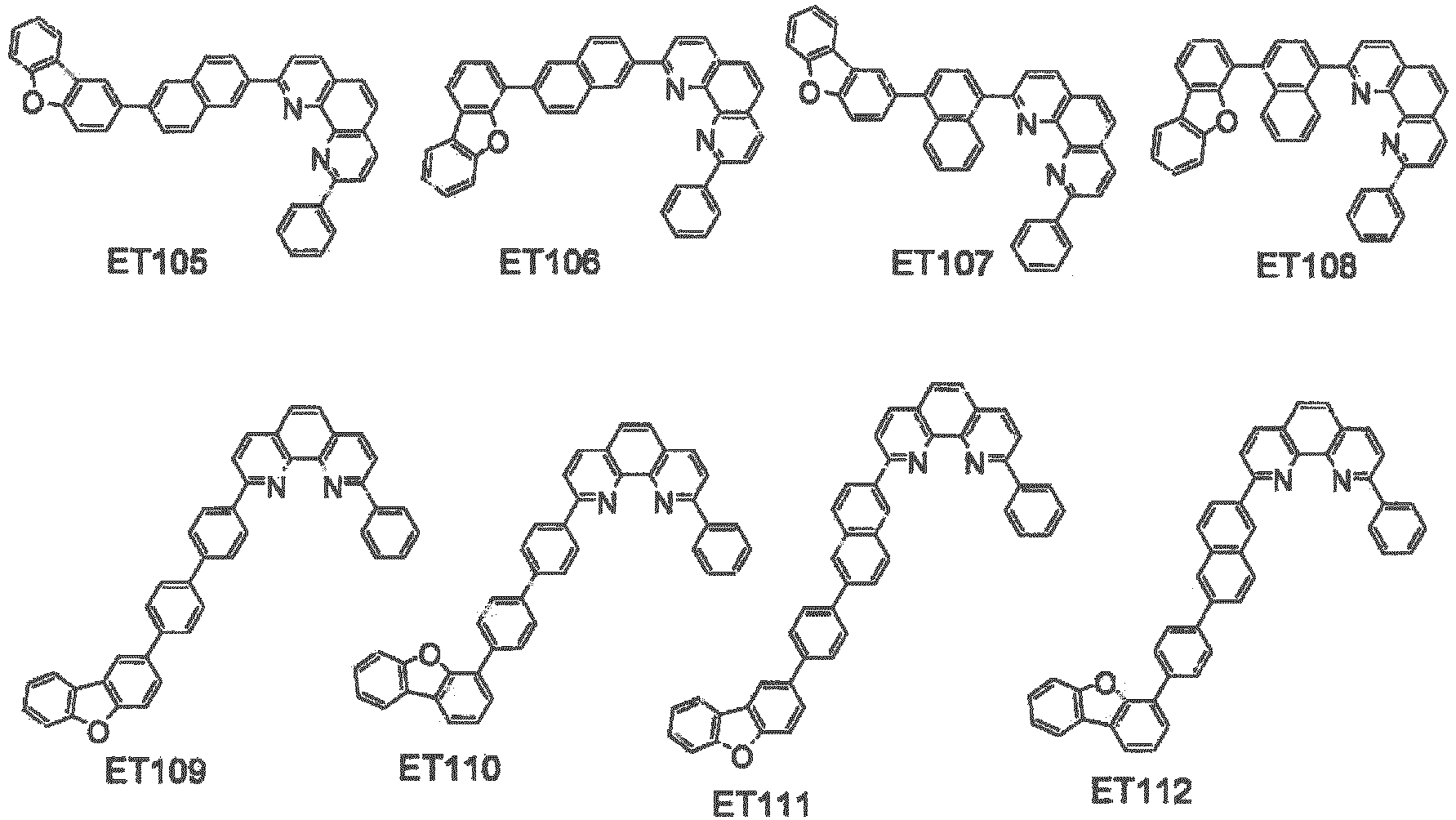




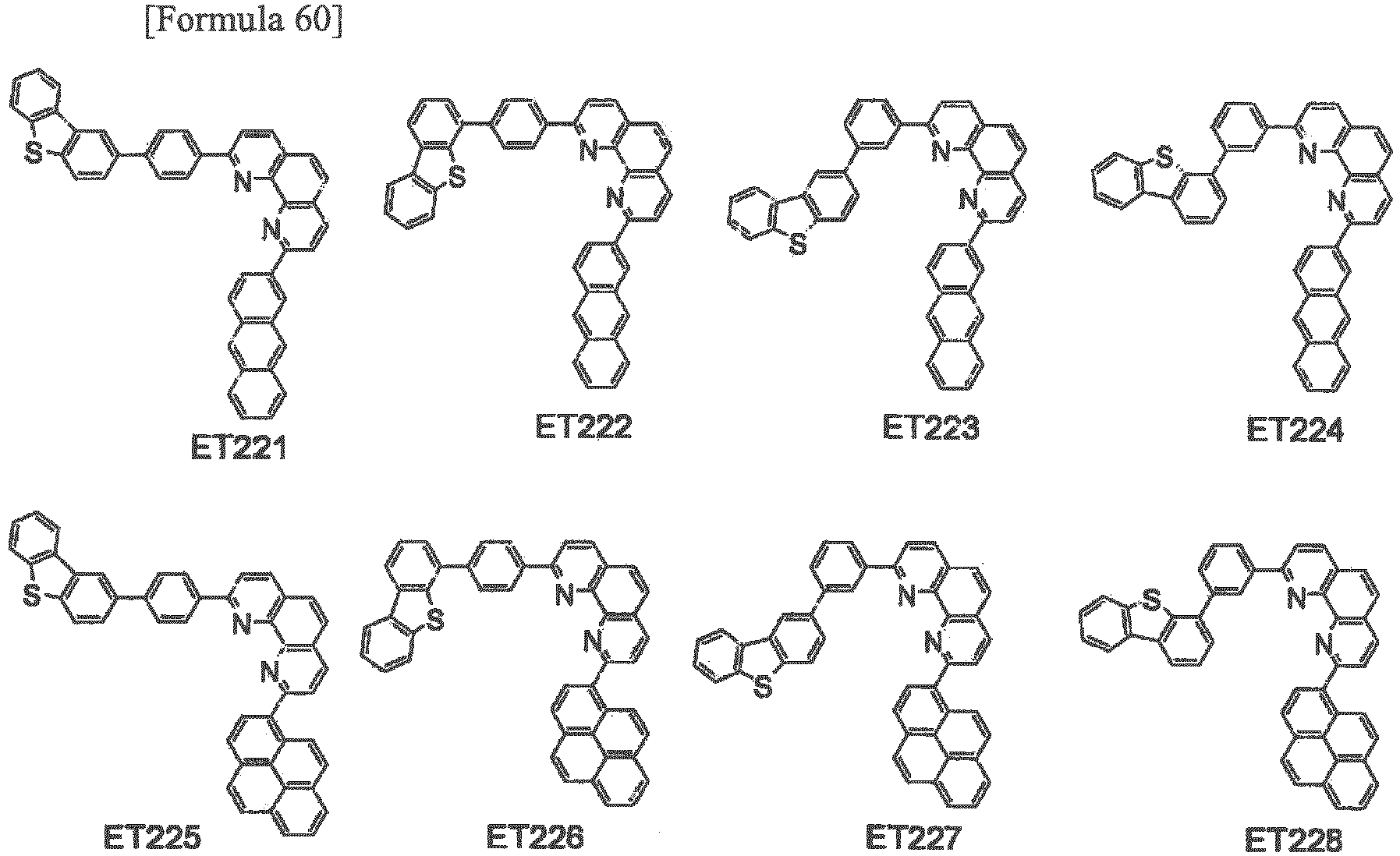


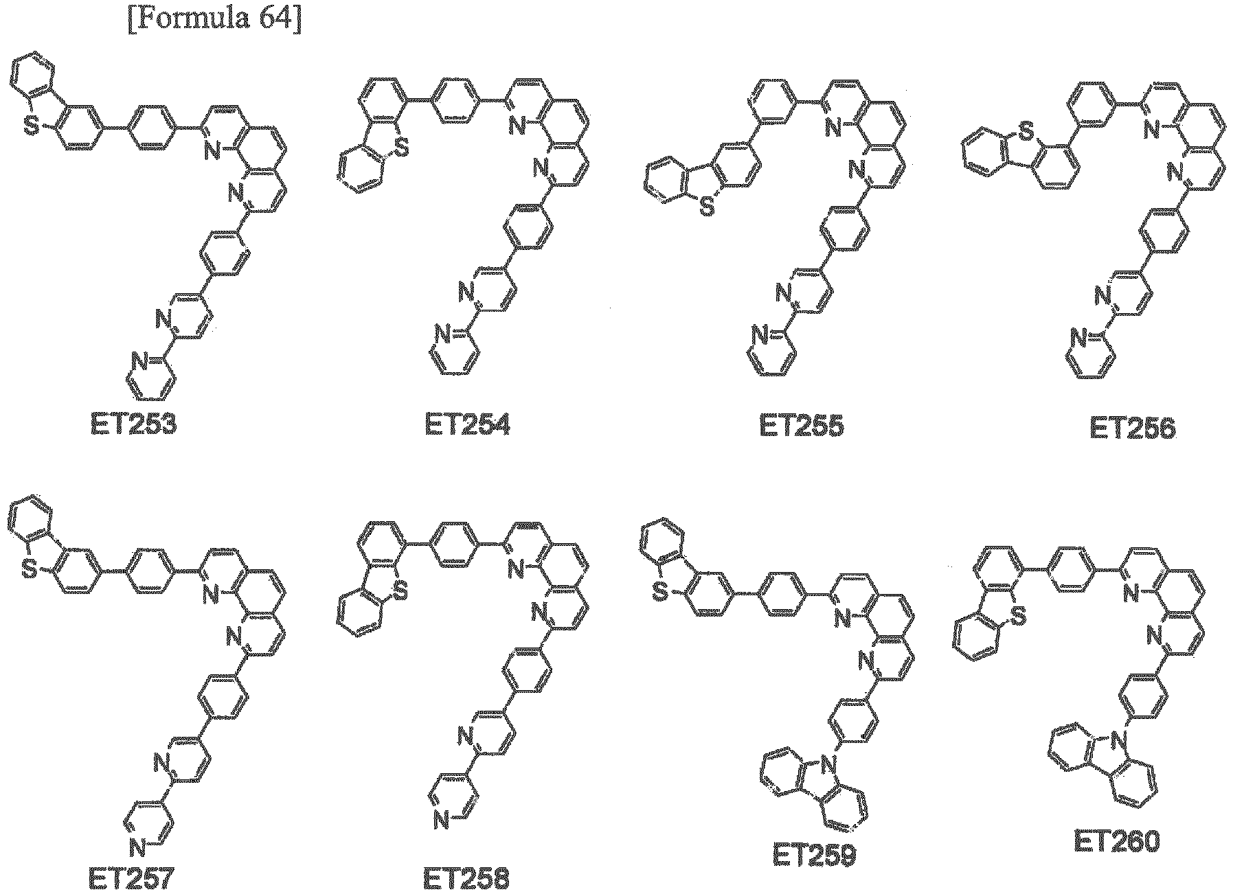



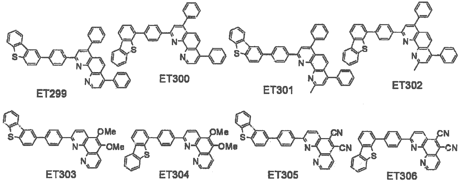



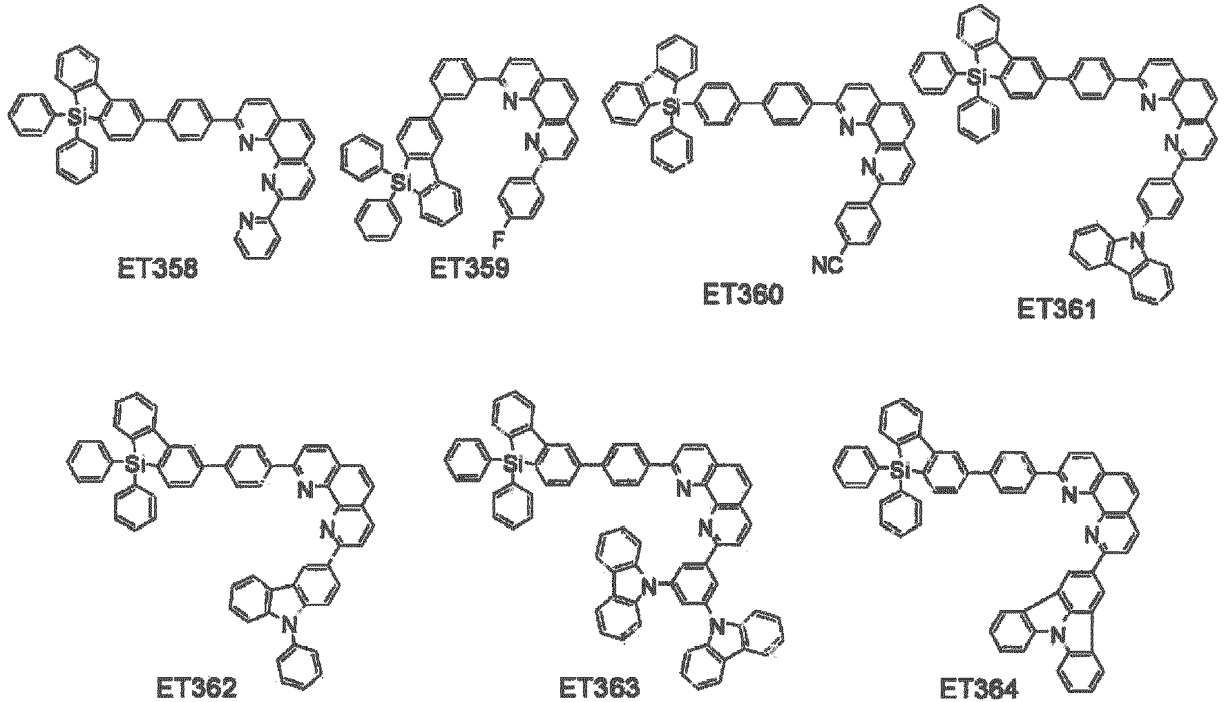


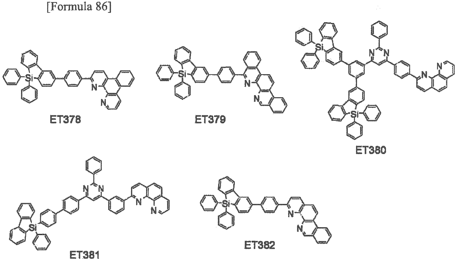


- Among the above compounds listed as the examples of the compound represented by the formula (1-7), preferable examples of the compound according to the exemplary embodiment are the compounds ET1 to ET156, ET160 to ET385 and ET1001 to ET1014 represented by the formula (1-7) in which X2 to X8 are CRX. Further preferable examples of the compound according to the exemplary embodiment are the compounds ET1 to ET156, ET160 to ET341 and ET1001 to ET1012 represented by the formula (1-7) in which X2 to X8 are CRX and Z is an oxygen atom or a sulfur atom. More preferable examples of the compound according to the exemplary embodiment are the compounds ET1 to ET156, ET160 to ET172 and ET1001 to ET106 represented by the formula (1-7) in which X2 to X8 are CRX and Z is an oxygen atom.
-


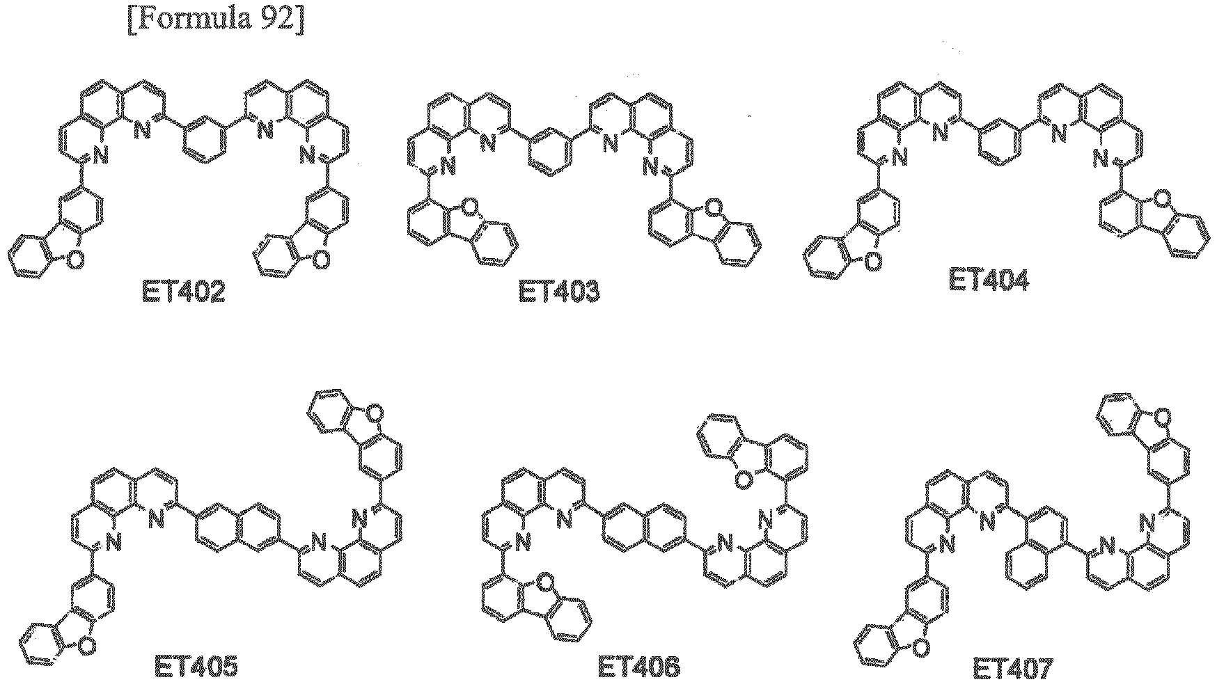


- Among the above compounds listed as the examples of the compound represented by the formula (1-8), preferable examples of the compound according to the exemplary embodiment are the compounds ET157 to ET159 and ET387 to ET470 represented by the formula (1-8) in which X2 to X7 are CRX. Further preferable examples of the compound according to the exemplary embodiment are the compounds ET157 to ET159, ET387 to ET424 and ET430 to ET459 represented by the formula (1-8) in which X2 to X7 are CRX and Z is an oxygen atom or a sulfur atom. More preferable examples of the compound according to the exemplary embodiment are the compounds ET157 to ET159 and ET387 to ET417 represented by the formula (1-7) in which X2 to X7 are CRX and Z is an oxygen atom.
- Examples of the compound represented by the formula (1-9) are as follows.


- Among the above compounds listed as the examples of the compound represented by the formula (1-9), preferable examples of the compound according to the exemplary embodiment are the compounds ET471 to ET474 represented by the formula (1-9) in which X1, X2, X4, X5, X7 and X8 are CRX. Further preferable examples of the compound according to the exemplary embodiment are the compounds ET471 to ET473 represented by the formula (1-9) in which X1, X2, X4, X5, X7 and X8 are CRX and Z is an oxygen atom or a sulfur atom. More preferable examples of the compound according to the exemplary embodiment are the compounds ET471 to ET472 represented by the formula (1-9) in which X1, X2, X4, X5, X7 and X8 are CRX and Z is an oxygen atom.
- Examples of the compound represented by the formula (1-10) are as follows.


- Among the above compounds listed as the examples of the compound represented by the formula (1-10), preferable examples of the compound according to the exemplary embodiment are the compounds ET475 to ET479 represented by the formula (1-10) in which X1 and X3 to X8 are CRX. Further preferable examples of the compound according to the exemplary embodiment are the compounds ET475 to ET478 represented by the formula (1-10) in which X3 to X8 are CRX and Z is an oxygen atom or a sulfur atom. More preferable examples of the compound according to the exemplary embodiment are the compounds ET475 to ET476 represented by the formula (1-10) in which X3 to X8 are CRX and Z is an oxygen atom.
- Examples of the compound represented by the formula (1-11) are as follows.


- Among the above compounds listed as the examples of the compound represented by the formula (1-11), preferable examples of the compound according to the exemplary embodiment are the compounds ET480 to ET485, ET487 to ET490 and ET492 to ET495 represented by the formula (1-11) in which X1, X2 and X4 to X8 are CRx. Further preferable examples of the compound according to the exemplary embodiment are the compounds ET480 to ET485, ET487 to ET490 and ET492 to ET493 represented by the formula (1-11) in which X1, X2 and X4 to X8 are CRx and Z is an oxygen atom or a sulfur atom. More preferable examples of the compound according to the exemplary embodiment are the compounds ET480 to ET485 represented by the formula (1-11) in which X1, X2 and X4 to X8 are CRx and Z is an oxygen atom.
- Examples of the compound represented by the formula (1-12) are as follows.


- Among the above compounds listed as the examples of the compound represented by the formula (1-12), preferable examples of the compound according to the exemplary embodiment are the compounds ET496 to ET509 represented by the formula (1-12) in which X1 to X3 and X5 to X8 are CRx. Further preferable examples of the compound according to the exemplary embodiment are the compounds ET496 to ET507 represented by the formula (1-12) in which X1 to X3 and X5 to X8 are CRX and Z is an oxygen atom or a sulfur atom. More preferable examples of the compound according to the exemplary embodiment are the compounds ET496 to ET501 represented by the formula (1-12) in which X1 to X3 and X5 to X8 are CRX and Z is an oxygen atom.
- Examples of the compound represented by the formula (1-13) are as follows.


- Among the above compounds listed as the examples of the compound represented by the formula (1-13), preferable examples of the compound according to the exemplary embodiment are the compounds ET510 to ET513 represented by the formula (1-13) in which X2 to X6 and X8 are CRx. Further preferable examples of the compound according to the exemplary embodiment are the compounds ET510 to ET513 represented by the formula (1-13) in which X2 to X6 and X8 are CRX and Z is an oxygen atom or a sulfur atom. More preferable examples of the compound according to the exemplary embodiment are the compounds ET510 to ET511 represented by the formula (1-13) in which X2 to X6 and X8 are CRX and Z is an oxygen atom.
- Examples of the compound represented by the formula (1-14) are as follows.


- Among the above compounds listed as the examples of the compound represented by the formula (1-14), preferable examples of the compound according to the exemplary embodiment are the compounds ET514 to ET530 represented by the formula (1-14) in which X1, X3 to X6 and X8 are CRx. Further preferable examples of the compound according to the exemplary embodiment are the compounds ET514 to ET529 represented by the formula (1-14) in which X1, X3 to X6 and X8 are CRX and Z is an oxygen atom or a sulfur atom. More preferable examples of the compound according to the exemplary embodiment are the compounds ET514 to ET521 represented by the formula (1-14) in which X1, X3 to X6 and X8 are CRX and Z is an oxygen atom.
- Examples of the compound represented by the formula (1-15) are as follows.


- Among the above compounds listed as the examples of the compound represented by the formula (1-15), preferable examples of the compound according to the exemplary embodiment are the compounds ET531 to ET534 represented by the formula (1-15) in which X3 to X6 are CRx. Further preferable examples of the compound according to the exemplary embodiment are the compounds ET531 to ET534 represented by the formula (1-15) in which X3 to X6 are CRX and Z is an oxygen atom or a sulfur atom. More preferable examples of the compound according to the exemplary embodiment are the compounds ET531 to ET532 represented by the formula (1-15) in which X3 to X6 are CRX and Z is an oxygen atom.
- Examples of the compound represented by the formula (1-16) are as follows.


- Among the above compounds listed as the examples of the compound represented by the formula (1-16), preferable examples of the compound according to the exemplary embodiment are the compounds ET535 to ET543 represented by the formula (1-16) in which X2, X4, X5 and X7 are CRx. Further preferable examples of the compound according to the exemplary embodiment are the compounds ET535 to ET542 represented by the formula (1-16) in which X2, X4, X5 and X7 are CRX and Z is an oxygen atom or a sulfur atom. More preferable examples of the compound according to the exemplary embodiment are the compounds ET535 to ET538 represented by the formula (1-16) in which X2, X4, X5 and X7 are CRX and Z is an oxygen atom.
- Further, specific examples of the compound represented by the formula (1) are shown below, but the invention is not limited to thereto.


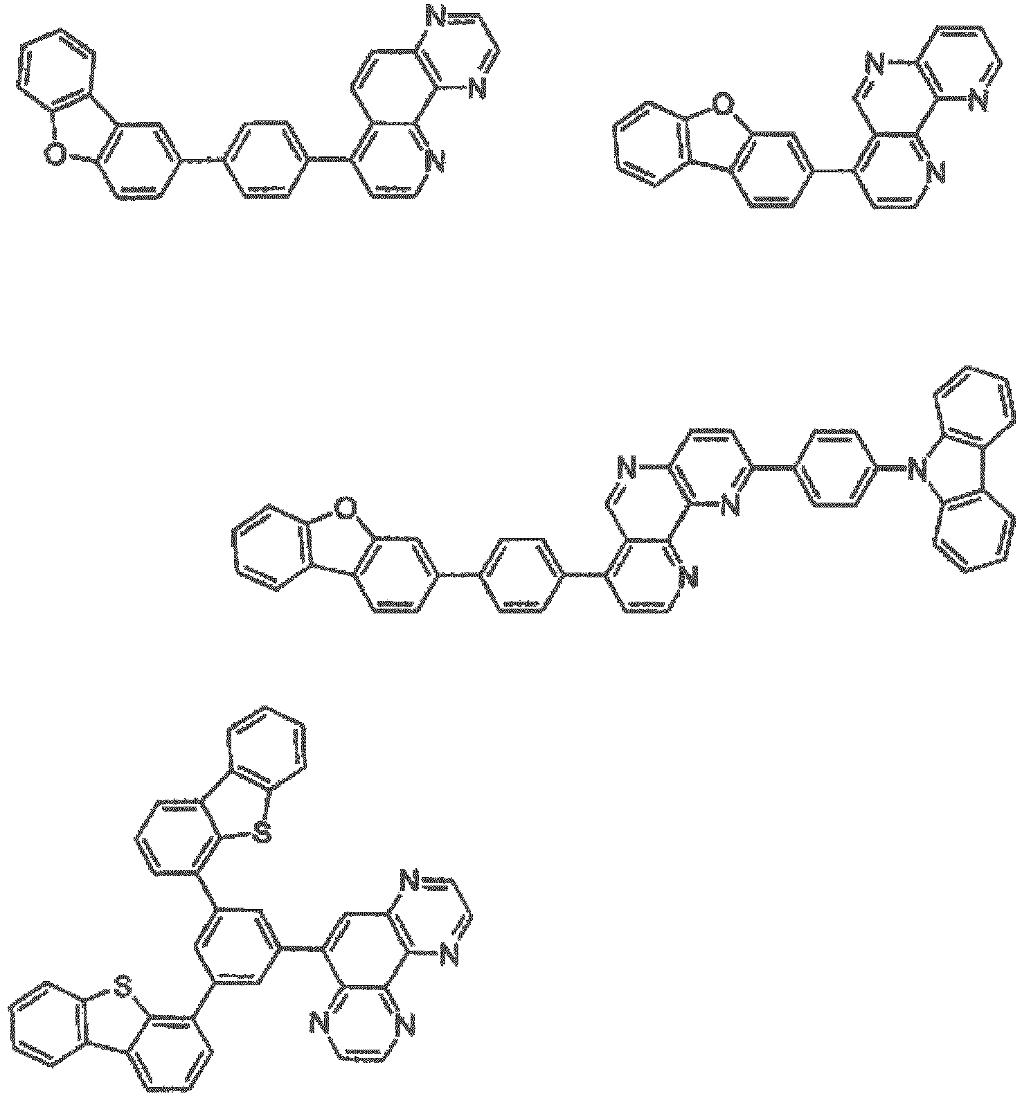
- The compound according to the exemplary embodiment is preferably contained in an organic compound layer between an anode and a cathode of an organic EL device. Moreover, in the organic EL device including an emitting layer and an electron transporting layer between the anode and the cathode, the compound according to the exemplary embodiment is more preferably contained in the electron transporting layer.
- A material for an organic EL device (also referred to as an organic-EL-device material) preferably contains the compound according to the exemplary embodiment. The organic-EL-device material may be composed solely of the compound represented by the formula (1), or alternatively, may contain another compound in addition to the compound represented by the formula (1). The organic-EL-device material according to the exemplary embodiment is usable for forming the organic compound layer of the organic EL device.
- The organic-EL-device material according to the exemplary embodiment is preferably contained in the organic compound layer between the anode and the cathode of the organic EL device. The organic-EL-device material according to the exemplary embodiment is more preferably contained in the electron transporting layer of the organic EL device, the organic EL device including the emitting layer and the electron transporting layer between the anode and the cathode.
- Typical device arrangements of an organic EL device include the following arrangements (a) to (e) and the like:
- (a) anode/ emitting layer/ cathode;
- (b) anode / hole injecting·transporting layer / emitting layer / cathode;
- (c) anode / emitting layer / electron injecting·transporting layer / cathode;
- (d) anode / hole injecting·transporting layer / emitting layer / electron injecting·transporting layer / cathode; and
- (e) anode / hole injecting·transporting layer / emitting layer / blocking layer / electron injecting·transporting layer / cathode.
- While the arrangements (d) and (e) are preferably used among the above arrangements, the arrangement of the invention is not limited to the above arrangements.
- It should be noted that the aforementioned "emitting layer" is an organic layer having an emission function and, when a doping system is employed, containing a host material and a dopant material. At this time, the host material has a function to mainly promote recombination of electrons and holes and trap excitons within the emitting layer while the dopant material has a function to promote an efficient emission from the excitons obtained by the recombination. In a phosphorescent device, the host material has a function of trapping the excitons, which are generated mainly in the dopant, within the emitting layer.
- The "hole injecting/transporting layer (or hole injecting·transporting layer) means "at least one of a hole injecting layer and a hole transporting layer while the "electron injecting/transporting layer (or electron injecting·transporting layer) means "at least one of an electron injecting layer and an electron transporting layer. Herein, when the hole injecting layer and the hole transporting layer are provided, the hole injecting layer is preferably closer to the anode. When the electron injecting layer and the electron transporting layer are provided, the electron injecting layer is preferably closer to the cathode.
- In the exemplary embodiment, the electron transporting layer means an organic layer having the highest electron mobility among organic layer(s) providing an electron transporting zone existing between the emitting layer and the cathode. When the electron transporting zone is provided by a single layer, the single layer is the electron transporting layer. Moreover, in the phosphorescent organic EL device, a blocking layer having an electron mobility that is not always high may be provided as shown in the arrangement (e) between the emitting layer and the electron transporting layer in order to prevent diffusion of exciton energy generated in the emitting layer. Thus, the organic layer adjacent to the emitting layer does not always correspond to the electron transporting layer.
- In an exemplary embodiment of the invention, the organic EL device includes: the cathode; the anode; and the organic compound layer between the cathode and the anode. The organic compound layer at least includes the emitting layer and the electron transporting layer. Further, the organic compound layer may include a layer(s) employed in a known organic EL device such as a hole injecting layer, a hole transporting layer, an electron injecting layer, a hole blocking layer and an electron blocking layer. The organic compound layer may include an inorganic compound.
- The organic-EL-device material according to the exemplary embodiment is contained in the organic compound layer. When the organic compound layer is provided by a plurality of layers, the organic-EL-device material according to the exemplary embodiment is contained singularly or as a component of a mixture in at least one of the plurality of layers. The electron transporting layer preferably contains the organic-EL-device material according to the exemplary embodiment.
- The organic EL device according to the exemplary embodiment of the invention includes a light-transmissive substrate, the anode, the cathode, and the organic compound layer disposed between the anode and the cathode.
- The organic compound layer includes the hole injecting layer, the hole transporting layer, the emitting layer, the hole blocking layer, the electron transporting layer and the electron injection layer in this order from the anode.
- The electron transporting layer of the organic EL device according to the exemplary embodiment contains a compound represented by a formula (10) below.

- In the formula (10), X1 to X8 each independently represent a carbon atom to be bonded to a group represented by a formula (20) below, CRX or a nitrogen atom. At least one of X1 to X8 is a carbon atom to be bonded to the group represented by the formula (20).
- RX is each independently selected from the group consisting of a hydrogen atom, halogen atom, hydroxyl group, cyano group, nitro group, carboxyl group, sulfonyl group, boryl group, phosphino group, mercapto group, acyl group, substituted or unsubstituted amino group, substituted or unsubstituted silyl group, substituted or unsubstituted alkyl group having 1 to 30 carbon atoms, substituted or unsubstituted alkenyl group having 2 to 30 carbon atoms, substituted or unsubstituted alkynyl group having 2 to 30 carbon atoms, substituted or unsubstituted aralkyl group having 6 to 30 carbon atoms, substituted or unsubstituted aryl group having 6 to 40 ring carbon atoms, and substituted or unsubstituted heteroaryl group having 5 to 40 ring atoms.
- In the formula (10), RX of adjacent ones of CRX in X1 to X8 may be bonded to each other to form a cyclic structure or may not be bonded.

- In the formula (20), b is an integer of 1 to 5. In the formula (20), c is an integer of 1 to 8.
- In the formula (20), Z represents an oxygen atom, sulfur atom or silicon atom. When b is from 2 to 5, a plurality of Z are mutually the same or different. When Z is a silicon atom, R9 and R10 are bonded to the silicon atom. R9 and R10 each independently represent the same as RX in the formula (10). R9 and R10 may be bonded to the structure represented by the formula (10).
- In the formula (20), L is selected from a single bond and a linking group. The linking group represents a substituted or unsubstituted polyvalent linear, branched or cyclic aliphatic hydrocarbon group having 1 to 30 carbon atoms, a substituted or unsubstituted polyvalent aryl group having 6 to 40 ring carbon atoms, or a substituted or unsubstituted polyvalent heteroaryl group having 5 to 40 ring atoms. The polyvalent heteroaryl group having 5 to 40 ring atoms in L of the formula (20) includes a substituted or unsubstituted polyvalent group derived from a phenanthroline ring represented by the formula (10). When c is from 2 to 8, a plurality of L are mutually the same or different.
- In the formula (20), Y1 to Y8 each independently represent a nitrogen atom, CRY or a carbon atom to be bonded to L.
- In the formula (20), RY represents the same as RX in the formula (10). The heteroaryl group having 5 to 40 ring atoms in RY includes a substituted or unsubstituted phenanthrolyl group derived from the phenanthroline ring represented by the formula (10). In the formula (20), adjacent ones of RY may be bonded to each other to form a cyclic structure or may not be bonded.
- X1 to X8 in the formula (10) respectively represent the same as X1 to X8 in the formula (1).
- Y1 to Y8, Z, L, b and c in the formula (20) respectively represent the same as Y1 to Y8, Z, L, b and c in the formula (2).
- The substituents in the formulae (10) and (20) represent the same as the substituents described in the formulae (1), (1-1) to (1-16), (2), (2-1), (1-x) (1-xx-1) and (1-xx-2).
- The formula (20) in which a substituted or unsubstituted polyvalent group derived from the phenanthroline ring represented by the formula (10) is included in L is exemplarily represented by a formula (20-1) below. In the formula (20-1), A1 represents the structure represented by the formula (10).

- In the formula (20-1), cx is an integer of 0 to 7, cy is an integer of 0 to 7 and 0≤cx+cy≤7. In the formulae (20-1), X1 to X8 of A1, Y1 to Y8, Z, L and b respectively represent the same as X1 to X8, Y1 to Y8, Z, L and b in the formulae (10) and (20).
- The formula (20) in which RY of CRY is a substituted or unsubstituted phenanthrolyl group derived from the phenanthroline ring represented by the formula (10) is exemplarily represented by a formula (10-1) below. In the formula (10-1), A2 and A3 represent the structure represented by the formula (10).

- In the formula (10-1), c1 is an integer of 1 to 8 and c2 is an integer of 1 to 8. In the formula (10-1), L1 and L2 each independently represent the same as L in the formula (20). In the formula (10-1), X1 to X8 in A2 and A3, Y1 to Y8, Z and b respectively represent the same as X1 to X8, Y1 to Y8, Z and b in the formulae (10) and (20).
- The formula (20) in which a substituted or unsubstituted polyvalent group derived from the phenanthroline ring represented by the formula (10) is included in L and in which RY of CRY is the substituted or unsubstituted phenanthrolyl group derived from the phenanthroline ring represented by the formula (10) is exemplarily represented by a formula (10-2) below. In the formula (10-2), A1, A2 and A3 represent the structure represented by the formula (10).

- In the formula (10-2), X1 to X8 in A1, A2 and A3, Y1 to Y8, Z, L1 to L3, b, cx, cy and c1 respectively represent the same as X1 to X8, Y1 to Y8, Z L1 to L3, b, cx, cy and c1 in the formulae (10), (20), (10-1) and (20-1).
- In the organic EL device according to the exemplary embodiment, X1 or X8 in the formula (10) is preferably a carbon atom to be bonded to the group represented by the formula (20).
- In the organic EL device according to the exemplary embodiment, X1 and X8 in the formula (10) are preferably carbon atoms to be bonded to the group represented by the formula (20).
- In the organic EL device according to the exemplary embodiment, X3 and X6 in the formula (10) are preferably carbon atoms to be bonded to the group represented by the formula (20).
- In the organic EL device according to the exemplary embodiment, X2 or X7 in the formula (10) is preferably a carbon atom to be bonded to the group represented by the formula (20).
- In the organic EL device according to the exemplary embodiment, X3 or X6 in the formula (10) is preferably a carbon atom to be bonded to the group represented by the formula (20).
- In the organic EL device according to the exemplary embodiment, X4 or X5 in the formula (10) is preferably a carbon atom to be bonded to the group represented by the formula (20).
- In the organic EL device according to the exemplary embodiment, X1 and X7 in the formula (10) are preferably carbon atoms to be bonded to the group represented by the formula (20).
- In the organic EL device according to the exemplary embodiment, X2 and X7 in the formula (10) are preferably carbon atoms to be bonded to the group represented by the formula (20).
- In the organic EL device according to the exemplary embodiment, X1, X2, X7 and X8 in the formula (10) are preferably carbon atoms to be bonded to the group represented by the formula (20).
- In the organic EL device according to the exemplary embodiment, X1, X3, X6 and X8 in the formula (10) are preferably carbon atoms to be bonded to the group represented by the formula (20).
- In the organic EL device according to the exemplary embodiment, X1 or X8 in the formula (10) is preferably a carbon atom to be bonded to the group represented by the formula (20). X1 and X8 in the formula (10) are more preferably carbon atoms to be bonded to the group represented by the formula (20).
- In the organic EL device according to the exemplary embodiment, in the formulae (10) and (10-1) to (10-2), the rest of X1 to X8 except for the carbon atom to be bonded to the group represented by the formula (20) are preferably CRX, in which RX is more preferably a hydrogen atom, alkyl group or aryl group, further preferably a hydrogen atom or a phenyl group.
- Moreover, in the organic EL device according to the exemplary embodiment, Z in the formula (20) is preferably an oxygen atom or a sulfur atom, more preferably an oxygen atom.
- It is also preferable that the electron transporting layer of the organic EL device according to the exemplary embodiment contains at least one of an electron-donating dopant and an organic metal complex. A content of the electron-donating dopant or the organic metal complex in the electron transporting layer is preferably in a range of 1 mass% to 50 mass%.
- The electron-donating dopant material is preferably at least one material selected from the group consisting of an alkali metal, alkali earth metal, rare earth metal, oxide of alkali metal, halide of alkali metal, oxide of alkali earth metal, halide of alkali earth metal, oxide of rare earth metal, and halide of rare earth metal.
- The organic metal complex is preferably at least one selected from the group consisting of an oganic metal complex including an alkali metal, oganic metal complex including an alkali earth metal, and oganic metal complex including a rare earth metal.
- The electron-donating dopant and organic metal complex are described in detail below.
- With the organic EL device in the exemplary embodiment, a drive voltage can be decreased since the electron transporting layer contains the compound represented by the formula (10). Moreover, since the electron transporting layer contains the compound represented by the formula (10) and at least one of the electron-donating dopant and the organic metal complex, the electron-donating dopant and/or the organic metal complex are easily captured by a phenanthroline skeleton represented by the formula (10), so that the drive voltage is further decreased.
- Moreover, the organic-EL-device material containing the compound represented by the formula (10) may be used for the organic EL device in the exemplary embodiment.
- The compound represented by the formula (10) encompasses the compound represented by the formula (1). Specific examples of the compound represented by the formula (10) are the same as the above-described specific examples of the compound represented by the formula (1) and compounds shown below, but the invention is not limited to thereto.

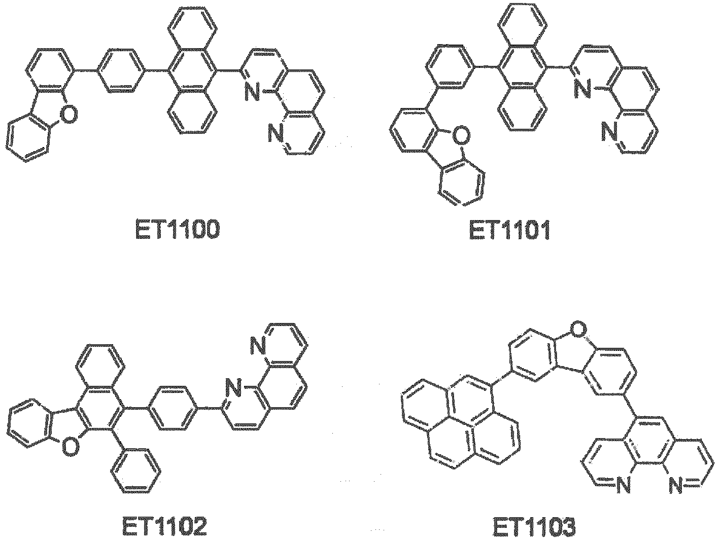


- The organic EL device according to the exemplary embodiment is formed on a light-transmissive substrate. The light-transmissive plate, which supports the organic EL device, is preferably a smooth substrate that transmits 50% or more of light in a visible region of 400 nm to 700 nm. Specifically, examples of the substrate are a glass plate and a polymer plate.
- The anode of the organic EL device is used for injecting holes into the hole injecting layer, the hole transporting layer or the emitting layer. It is effective that the anode has a work function of 4.5 eV or more. Specific examples of a material for the anode are alloys of indium-tin oxide (ITO), tin oxide (NESA), indium zinc oxide, gold, silver, platinum and copper.
- The cathode is preferably formed of a material with smaller work function in order to inject electrons into the electron injecting layer, the electron transporting layer and the emitting layer. Although a material for the cathode is not particularly limited, examples of the material are indium, aluminium, magnesium, alloy of magnesium and indium, alloy of magnesium and aluminium, alloy of aluminium and lithium, alloy of aluminium, scandium and lithium, and alloy of magnesium and silver.
- The emitting layer of the organic EL device has a function for providing conditions for recombination of the electrons and the holes to emit light. The emitting layer is preferably a molecular deposit film. The molecular deposit film means a thin film formed by depositing a material compound in gas phase or a film formed by solidifying a material compound in a solution state or in liquid phase. The molecular deposit film is typically distinguished from a thin film formed by the LB (Langmuir Blodgett) method (i.e., molecular accumulation film) by differences in aggregation structures and higher order structures and functional differences arising therefrom.
- The dopant material is selected from a known fluorescent material that emits fluorescence or a known phosphorescent material that emits phosphorescence.
- As a host material, any host material applicable to the organic EL device is used. Examples of the host material include an amine derivative, azine derivative and fused polycyclic aromatic derivative.
- Examples of the amine derivative are a monoamine compound, diamine compound, triamine compound, tetramine compound and amine compound substituted with a carbazole group.
- Examples of the azine derivative include a monoazine derivative, diazine derivative and triazine derivative.
- The fused polycyclic aromatic derivative is preferably a fused polycyclic aryl having no heterocyclic skeleton. Examples of the fused polycyclic aromatic derivative include the fused polycyclic aryl such as naphthalene, anthracene, phenanthrene, chrysene, fluoranthene and triphenylene, or derivatives thereof.
- The hole injecting·transporting layer helps injection of holes to the emitting layer and transports the holes to an emitting region. The hole injecting·transporting layer exhibits a large hole mobility and a small ionization energy.
- A material for forming the hole injecting layer and the hole transporting layer is preferably a material for transporting the holes to the emitting layer at a lower electric field intensity. For instance, an aromatic amine compound is preferably used. A material for the hole injecting layer is preferably a porphyrin compound, an aromatic tertiary amine compound or a styryl amine compound, particularly preferably the aromatic tertiary amine compound such as hexacyanohexaazatriphenylene (HAT).
- The electron injection/transport layer helps injection of the electron to the luminescent layer and has a high electron mobility. The electron injecting layer is provided for adjusting energy level, by which, for instance, sudden changes of the energy level can be reduced.
- In the exemplary embodiment, the electron injecting·transporting layer at least includes the electron transporting layer containing the compound represented by the formula (10). In addition to the electron transporting layer, the electron injecting·transporting layer may include an electron injecting layer or another electron transporting layer. The electron injecting·transporting layer may be formed by laminating a first electron transporting layer, second electron transporting layer and electron injecting layer in this order from the anode. In this arrangement, the compound represented by the formula (10) is preferably contained in the first electron transporting layer. When the organic EL device according to the exemplary embodiment includes a plurality of electron transporting layers, it is only required that the compound represented by the formula (10) is contained in at least one of the electron transporting layers. Preferably, the compound represented by the formula (10) is contained in the electron transporting layer closer to the emitting layer. Moreover, the electron transporting layer containing the compound represented by the formula (10) may contain an alkali metal as described above, or alternatively, may contain the following electron transrporting material in addition to the alkali metal.
- The organic EL device according to the exemplary embodiment preferably includes the electron injecting layer between the electron transporting layer and the cathode, in which the electron injecting layer preferably contains a nitorogen-containing cyclic derivative as a main component. The electron injecting layer may serve as the electron transporting layer. Noted that "as a main component" means that the nitrogen-containing cyclic derivative is contained in the electron injecting layer at a content of 50 mass% or more.
- The electron transporting material for forming the electron transporting layer or the electron injecting layer is preferably an aromatic heterocyclic compound having at least one heteroatom in the molecule, particularly preferably a nitrogen-containing cyclic derivative. The nitrogen-containing cyclic derivative is preferably an aromatic ring having a nitrogen-containing six-membered or five-membered ring skeleton, or a fused aromatic cyclic compound having a nitrogen-containing six-membered or five-membered ring skeleton.
- It is also preferable that the electron transporting layer of the organic EL device according to the exemplary embodiment contains at least one of the electron-donating dopant and the organic metal complex. With this arrangement, a decrease in the voltage applied on the organic EL device is enhanced. The electron-donating dopant may be at least one selected from an alkali metal, an alkali metal compound, an alkaline-earth metal, an alkaline-earth metal compound, a rare-earth metal, a rare-earth metal compound and the like.
- The organic metal complex may be at least one compound selected from an organic metal complex including an alkali metal, an organic metal complex including an alkali earth metal, and an organic metal complex including rare-earth metal.
- Examples of the alkali metal are lithium (Li) (work function: 2.93 eV), sodium (Na) (work function: 2.36 eV), potassium (K) (work function: 2.28 eV), rubidium (Rb) (work function: 2.16 eV) and cesium (Cs) (work function: 1.95 eV), among which a substance having a work function of 2.9 eV or less is particularly preferable. Among the above, the alkali metal is preferably K, Rb or Cs, more preferably Rb or Cs, the most preferably Cs.
- Examples of the alkali earth metal are calcium (Ca) (work function: 2.9 eV), strontium (Sr) (work function: 2.0 to 2.5 eV), and barium (Ba) (work function: 2.52 eV), among which a substance having a work function of 2.9 eV or less is particularly preferable.
- Examples of the rare-earth metal are scandium (Sc), yttrium (Y), cerium (Ce), terbium (Tb) and ytterbium (Yb), among which a substance having a work function of 2.9 eV or less is particularly preferable.
- Since the above preferred metals have particularly high reducibility, addition of a relatively small amount of the metals to an electron injecting zone can enhance luminance intensity and lifetime of the organic EL device.
- Examples of the alkali metal compound are an alkali oxide such as lithium oxide (Li2O), cesium oxide (Cs2O) and potassium oxide (K2O), and an alkali halogenide such as sodium fluoride (NaF), cesium fluoride (CsF) and potassium fluoride (KF), among which lithium fluoride (LiF), lithium oxide (Li2O) and sodium fluoride (NaF) are preferable.
- Examples of the alkali earth metal compound are barium oxide (BaO), strontium oxide (SrO), calcium oxide (CaO) and a mixture thereof, i.e., BaxSr1-xO(0<x<1), BaxCa1-xO(0<x<1), among which BaO, SrO and CaO are preferable.
- Examples of the rare-earth metal compound are ytterbium fluoride (YbF3), scandium fluoride (ScF3), scandium oxide (ScO3), yttrium oxide (Y2O3), cerium oxide (Ce2O3), gadolinium fluoride (GdF3) and terbium fluoride (TbF3), among which YbF3, ScF3 and TbF3 are preferable.
- The organic metal complex is not particularly limited, as long as the organic metal complex contains at least one of an alkali metal ion, alkali earth metal ion and rare-earth metal ion, as a metal ion. The ligand for each of the complexes is preferably quinolinol, benzoquinolinol, acridinol, phenanthridinol, hydroxyphenyl oxazole, hydroxyphenyl thiazole, hydroxydiaryl oxadiazole, hydroxydiaryl thiadiazole, hydroxyphenyl pyridine, hydroxyphenyl benzoimidazole, hydroxybenzo triazole, hydroxy fluborane, bipyridyl, phenanthroline, phthalocyanine, porphyrin, cyclopentadiene, β-diketones, azomethines, or a derivative thereof, but the ligand is not limited thereto.
- A preferable method for adding the electron-donating dopant and the organic metal complex includes dispersing at least one of the electron-donating dopant and the organic metal complex in the electron transporting layer while co-depositing at least one of the electron-donating dopant and the organic metal complex with the compound represented by the formula (1) by resistance heating deposition. A dispersion concentration is shown by a film thickness ratio of the compound represented by the formula (1) to the electron-donating dopant and/or the organic metal complex being of 1000:1 to 1:1000, preferably 100:1 to 1:1.
- When at least one of the electron-donating dopant and the organic metal complex forms a layer, after forming a layer of the compound represented by the formula (1), at least one of the electron-donating dopant and the organic metal complex is singularly deposited on the compound layer by resistance heating deposition to preferably form a 0.1 nm- to 15 nm-thick layer.
- When at least one of the electron-donating dopant and the organic metal complex forms an island pattern, after forming an island pattern of the compound represented by the formula (1), at least one of the electron-donating dopant and the organic metal complex is singularly deposited on the compound layer by resistance heating deposition to preferably form a 0.05 nm- to 1 nm-thick island pattern.
- A ratio of the compound represented by the formula (1) to at least one of the electron-donating dopant and the organic metal complex in the organic EL device according to the exemplary embodiment is preferably shown by a film thickness ratio of the main component to the electron-donating dopant and/or the organic metal complex being 100:1 to 1:1, more preferably 50:1 to 4:1.
- The organic EL device preferably includes a blocking layer such as an electron blocking layer, hole blocking layer or triplet blocking layer at a part adjacent to the emitting layer. Herein, the electron blocking layer prevents electrons from leaking from the emitting layer into the hole transporting layer while the hole blocking layer prevents holes from leaking from the emitting layer into the electron transporting layer. In the organic EL device according to the exemplary embodiment, the hole blocking layer is provided between the electron transporting layer and the emitting layer. The triplet blocking layer has a function of preventing triplet excitons generated in the emitting layer from diffusing into neighboring layers to trap the triplet excitons within the emitting layer, thereby suppressing energy deactivation of the triplet excitons on molecules other than the emitting dopant in the electron transporting layer.
- A method of forming each of the layers in the organic EL device according to the exemplary embodiment is not particularly limited. Conventionally-known methods such as vacuum deposition and spin coating may be employed for forming the layers. The organic layer, which is used in the organic EL device of the exemplary embodiment, may be formed by a known method such as vacuum deposition, molecular beam epitaxy (MBE (Molecular Beam Epitaxy) method) or coating methods using a solution such as a dipping, spin coating, casting, bar coating, and roll coating.
- A film thickness of the emitting layer is preferably in a range of 5 nm to 50 nm, more preferably in a range of 7 nm to 50 nm and most preferably in a range of 10 nm to 50 nm. By forming the emitting layer at the film thickness of 5 nm or more, the emitting layer is easily formable and chromaticity is easily adjustable. By forming the emitting layer at the film thickness of 50 nm or less, an increase in the drive voltage is suppressible.
- Although the film thickness of each of other organic layers is not specifically limited, the film thickness is preferably in a typical range of several nm to 1 µm. When the film thickness is provided in the above range, defects such as pin holes caused by an excessively thinned film can be avoided while an increase in the drive voltage caused by an excessively thickened film can be suppressed.
- It should be noted that the invention is not limited to the above exemplary embodiment but may include any modification and improvement as long as such modification and improvement are compatible with the invention.
- In the above exemplary embodiment, the organic EL device including the hole blocking layer between the emitting layer and the electron transporting layer containing the compound according to the exemplary embodiment is described as an example. However, the arrangement of the organic EL is not limited thereto.
- For instance, such an organic EL device that includes: the emitting layer; and the electron transporting layer containing the compound according to the exemplary embodiment, in which the emitting layer is adjacent to the electron transporting layer, is also preferable.
- The emitting layer is not limited to a single layer, but may be provided as a laminate by a plurality of emitting layers. When the organic EL device includes the plurality of emitting layers, the plurality of emitting layers may be each independently a fluorescent emitting layer or a phosphorescent emitting layer.
- When the organic EL device includes the plurality of emitting layers, the plurality of emitting layers may be adjacent to each other, or may be laminated on each other via an intermediate layer to provide a so-called tandem-type organic EL device.
- It is also preferable that the organic EL device contains at least one of the electron-donating dopant and the organic metal complex in an interfacial region between the cathode and the organic compound layer. With this arrangement, the organic EL device can emit light with enhanced luminance intensity and have a longer lifetime. Examples of the electron-donating dopant and the organic metal complex are the same as described above.
- The electron-donating dopant and the organic metal complex are added to preferably form a layer or an island pattern in the interfacial region. The layer of the electron-donating dopant or the island pattern of the organic metal complex is preferably formed by: depositing at least one of the electron-donating dopant and the organic metal complex while simultaneously depositing an organic substance that is an emitting material or an electron-injecting material for forming the interfacial region, by resistance heating deposition; and dispersing at least one of the electron-donating dopant and an organic metal complex reduction-causing dopant in the organic substance.
- In the invention, it is also preferable that the emitting layer contains an assistance material for assisting injection of charges. When the emitting layer is formed of a host material that exhibits a wide energy gap, a difference in ionization potential (Ip) between the host material and the hole injecting/transporting layer etc. becomes so large that injection of the holes into the emitting layer becomes difficult, which may cause a rise in a driving voltage required for providing sufficient luminance. In the above instance, since a hole-injectable or hole-transportable assistance substance for assisting injection of charges is contained in the emitting layer, holes can be easily inject-d into the emitting layer and the drive voltage can be decreased.
- As the assistance substance for assisting the injection of charges, for instance, a typical hole injecting·transporting material is usable.
- Specific examples of the material for assisting the injection of charges are a triazole derivative, oxadiazole derivative, imidazoles derivative, polyarylalkane derivative, pyrazoline derivative, pyrazolone derivative, phenylenediamine derivative, arylamine derivative, amino-substituted chalcone derivative, oxazole derivative, fluorenone derivative, hydrazone derivative, stilbene derivative, silazane derivative, polysilane copolymer, aniline copolymer, and conductive polymer oligomer (particularly, a thiophene oligomer).
- The hole injecting material is exemplified by the above. The hole injecting material is preferably a porphyrin compound, aromatic tertiary amine compound and styryl amine compound, particularly preferably aromatic tertiary amine compound.
- The organic EL device of the invention is suitably applicable to an electronic device such as: a display of a television, a mobile phone, a personal computer and the like; and an emitting unit of an illuminator or a vehicle light.
- Next, the invention will be described in further detail by exemplifying Example(s) and Comparative(s). However, the invention is not limited by the description of Example(s).
- A synthesis scheme of a compound 5 is shown below.

- In synthesizing the compound 5, a compound 2 was initially synthesized.
- Under an argon gas atmosphere, 1,4-dibromobenzene (50 g, 211 mmol) was dissolved in diethylether (350 mL). After the obtained solution was cooled to 0 degrees C, n-butyllithium (2.69 M hexane solution)(72 mL, 194 mmol) was dropped into the cooled solution for 30 minutes. The obtained mixture solution was further stirred for 30 minutes. The prepared p-bromophenyl lithium was dropped at 0 degrees C for 45 minutes in a suspension liquid in which 1,10-phenanthroline (15 g, 85 mmol) as a compound 1 was suspended in diethylether (350 mL). The obtained mixture solution was further stirred for five hours. After the completion of the reaction, water was dropped at 0 degrees C for 30 minutes in the obtained reaction solution. The reaction solution was extracted with dichloromethane. A solvent except for 200 mL of dichloromethane was distilled under reduced pressure. Manganese dioxide (150 g) was added to the obtained solution and stirred at the room temperature for 4.5 hours. Subsequently, magnesium sulfate was added to the reaction solution. The obtained deposit was subjected to filtration and a solvent was distilled under reduced pressure. A residue was purified by silica-gel column chromatography (dichloromethane/hexane/methanol). The obtained solid was washed with methanol and dried under reduced pressure, so that a compound 2 (23 g, a yield of 81%) was obtained as a white solid. By FD-MS (Field Desorption Mass Spectrometry) analysis, the obtained compound was identified to be the compound 2.
- A compound 3 (18 g, a yield of 55%) was obtained as a white solid in the same manner as in the (1-1) synthesis of the compound 2, except for using the compound 2 (23 g, 68 mmol) in place of the compound 1. By FD-MS (Field Desorption Mass Spectrometry) analysis, the obtained compound was identified to be the compound 3.
- The compound 3 (6.0 g, 12 mmol) and a compound 4 (5.7 g, 27 mmol) were suspended in 1,2-dimethoxyethane (200 mL), to which tetrakis(triphenylphosphine)palladium(0) (0.7 g, 0.61 mmol) and an aqueous solution of 2M sodium carbonate (37 mL) were added. The obtained solution was heated to reflux for seven hours. After the completion of the reaction, water was added to the reaction solution and the reaction solution was filtrated to obtain a solid. The obtained solid was washed with water and methanol and dried under reduced pressure. The obtained crude product was purified by silica-gel column chromatography (dichloromethane). The obtained solid was washed with methanol and dried under reduced pressure, so that a compound 5 (7.2 g, a yield of 88%) was obtained as a white solid. By FD-MS (Field Desorption Mass Spectrometry) analysis, the obtained compound was identified to be the compound 5.
- A synthesis scheme of a compound 9 is shown below.

- A compound 6 (24 g, a yield of 83%) was obtained as a yellow solid in the same manner as in the (1-1) synthesis of the compound 2, except for using phenyllithium (1.6M butylether solution)(139 mL, 222 mmol) in place of p-bromophenyllithium, the phenyllithium being used at 2 molar equivalent to 1,10-phenanthroline. By FD-MS (Field Desorption Mass Spectrometry) analysis, the obtained compound was identified to be the compound 6.
- A compound 7 (12 g, a yield of 76%) was obtained as a yellow solid in the same manner as in the (1-1) synthesis of the compound 2, except for using the compound 6 (10 g, 39 mmol) in place of the compound 1. By FD-MS (Field Desorption Mass Spectrometry) analysis, the obtained compound was identified to be the compound 7.
- A compound 9 (1.7g, a yield of 23%) was obtained as a white solid in the same manner as in (1-3) synthesis of the compound 5, except for using the compound 7(6.0g, 15 mmol) in place of the compound 3 and using the compound 8 (3.4 g, 16 mmol) in place of the compound 4. By FD-MS (Field Desorption Mass Spectrometry) analysis, the obtained compound was identified to be the compound 9.
- A synthesis scheme of a compound 10 is shown below.
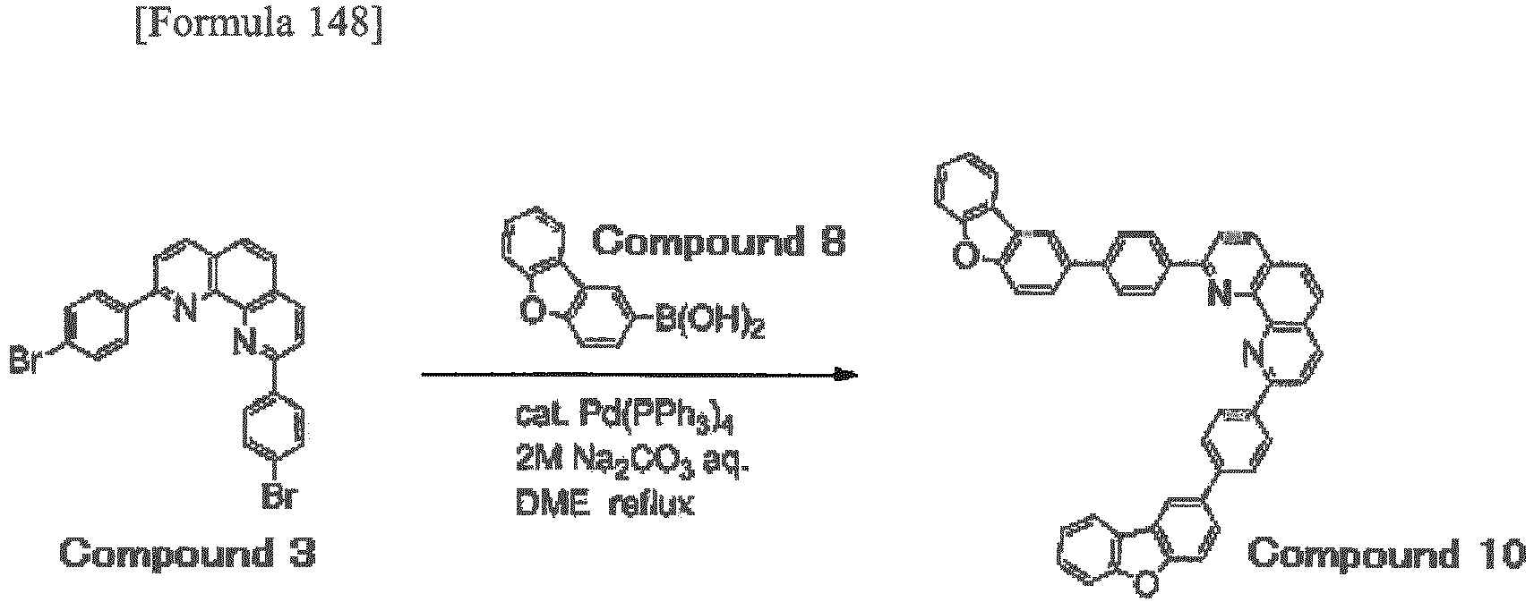
- A compound 10 (0.25oz, a yield of 80%) was obtained as a white solid in the same manner as in the (1-3) synthesis of the compound 5, except for using the compound 8 (6.3 g, 30 mmol) in place of the compound 4. By FD-MS (Field Desorption Mass Spectrometry) analysis, the obtained compound was identified to be the compound 10.
- A synthesis scheme of a compound 13 is shown below.
-

- A compound 12 (6.5 g, a yield of 67%) was obtained as a yellow solid in the same manner as in the (1-1) synthesis of the compound 2, except for using the compound 11 (17 g, 69 mmol) in place of 1,4-dibromobenzene. By FD-MS (Field Desorption Mass Spectrometry) analysis, the obtained compound was identified to be the compound 12.
- A compound 13 (2.1 g, a yield of 22%) was obtained as a light yellow solid in the same manner as in (1-1) synthesis of the compound 2, except for using the compound 12 (6.5 g, 19 mmol) in place of the compound 1 and using the compound 11 (12 g, 47 mmol) in place of 1,4-dibromobenzene. By FD-MS (Field Desorption Mass Spectrometry) analysis, the obtained compound was identified to be the compound 13.
- A synthesis scheme of a compound 1C is shown below.


- The compound 1C was synthesized according to the above scheme in the same manner as in the synthesis of the compound 13 except for using 2-bromodibenzofuran in place of the compound 11.
- A synthesis scheme of a compound 1D is shown below.

- The compound 1D was synthesized according to the above scheme in the same manner as in the synthesis of the compound 13 except for using 2,8-bromodibenzofuran in place of the compound 11.
- A synthesis scheme of a compound 16 is shown below.

- The compound 16 (8.6 g, a yield of 83%) was obtained as a white solid in the same manner as in (1-3) synthesis of the compound 5, except for using the compound 14 (5.0 g, 15 mmol) in place of the compound 3 and using the compound 15 (9.9 g, 33 mmol) in place of the compound 4. By FD-MS (Field Desorption Mass Spectrometry) analysis, the obtained compound was identified to be the compound 16.
- A synthesis scheme of a compound 19 is shown below.


- A compound 17 (13 g, a yield of 86%) was obtained as a white solid in the same manner as in the (1-3) synthesis of the compound 5, except for using the compound 14 (10 g, 30 mmol) in place of the compound 3. By FD-MS (Field Desorption Mass Spectrometry) analysis, the obtained compound was identified to be the compound 17.
- A compound 18 (9.6 g, a yield of 56%) was obtained as a yellow solid in the same manner as in (1-1) synthesis of the compound 2, except for using the compound 17 (13 g, 25 mmol) in place of the compound 1 and using the compound 11 (16 g, 63 mmol) in place of 1,4-dibromobenzene. By FD-MS (Field Desorption Mass Spectrometry) analysis, the obtained compound was identified to be the compound 18.
- A compound 19 (3.2 g, a yield of 27%) was obtained as a light yellow solid in the same manner as in (1-1) synthesis of the compound 2, except for using the compound 18 (9.6 g, 14 mmol) in place of the compound 1 and using the compound 11 (8.7 g, 35 mmol) in place of 1,4-dibromobenzene. By FD-MS (Field Desorption Mass Spectrometry) analysis, the obtained compound was identified to be the compound 19.
- A synthesis scheme of a compound 22 is shown below.

- The compound 22 (6.5 g, a yield of 63%) was obtained as a white solid in the same manner as in (1-3) synthesis of the compound 5, except for using the compound 20 (5.0 g, 15 mmol) in place of the compound 3 and using the compound 21 (9.9 g, 33 mmol) in place of the compound 4. By FD-MS (Field Desorption Mass Spectrometry) analysis, the obtained compound was identified to be the compound 22.
- A synthesis scheme of a compound 26 is shown below.


- A compound 23 (13 g, a yield of 89%) was obtained as a white solid in the same manner as in (1-3) synthesis of the compound 5, except for using the compound 20 (10 g, 30 mmol) in place of the compound 3 and using the compound 8 (16 g, 65 mmol) in place of the compound 4. By FD-MS (Field Desorption Mass Spectrometry) analysis, the obtained compound was identified to be the compound 23.
- A compound 25 (6.2 g, a yield of 36%) was obtained as a yellow solid in the same manner as in (1-1) synthesis of the compound 2, except for using the compound 23 (13 g, 25 mmol) in place of the compound 1 and using the compound 24 (16 g, 63 mmol) in place of 1,4-dibromobenzene. By FD-MS (Field Desorption Mass Spectrometry) analysis, the obtained compound was identified to be the compound 25.
- A compound 26 (2.1 g, a yield of 27%) was obtained as a light yellow solid in the same manner as in (1-1) synthesis of the compound 2, except for using the compound 25 (6.2 g, 9.1 mmol) in place of the compound 1 and using the compound 24 (5.6 g, 23 mmol) in place of 1,4-dibromobenzene. By FD-MS (Field Desorption Mass Spectrometry) analysis, the obtained compound was identified to be the compound 26.
-

- A compound 28 (7.6 g, a yield of 98%) was obtained as a brown oily substance in the same manner as in (1-1) synthesis of the compound 2, except for using the compound 6 (4.0 g, 16 mmol) in place of the compound 1, using the compound 27 (10 g, 31 mmol) in place of 1,4-dibromobenzene, and using n-butyllithium at 0.95 molar equivalent to the compound 1. By FD-MS (Field Desorption Mass Spectrometry) analysis, the obtained compound was identified to be the compound 28.
- A compound 29 (4.9 g, a yield of 48%) was obtained as a light yellow solid in the same manner as in (1-1) synthesis of the compound 2, except for using the compound 6 (4.7 g, 18 mmol) in place of the compound 1 and using the compound 28 (7.6 g, 15 mmol) in place of 1,4-dibromobenzene. By FD-MS (Field Desorption Mass Spectrometry) analysis, the obtained compound was identified to be the compound 29.
- A synthesis scheme of a compound 1A is shown below,

- Under an argon gas atmosphere, p-(5,5-dimethyl-1,3-dioxane-2-yl)bromobenzene (15.4 g, 56.8 mmol) was dissolved in tetrahydrofuran (100 mL). After the obtained solution was cooled to minus 78 degrees C, t-butyllithium (1.3 M hexane solution) (45.9 mL, 59.6 mmol) was dropped in the cooled solution for 20 minutes. The obtained mixture solution was further stirred for two hours. Subsequently, the mixture solution was gradually heated up to 0 degrees C. To the obtained solution, a solution in which 1,10-phenanthroline (10.2 g, 56.8 mmol) was dissolved in tetrahydrofuran (50 mL) was added. The obtained mixture solution was stirred for eight hours at the room temperature. After the completion of the reaction, water (80 mL) was added at 0 degrees C to the obtained solution. The solution was extracted with dichloromethane, to which manganese dioxide (60 g) was added. After being stirred for four hours at the room temperature, the obtained solution was dried with magnesium sulfate and a solvent was distilled under reduced pressure. A residue was purified by silica-gel column chromatography, so that a compound T1 (8.41 g, a yield of 40%) was obtained.
- The compound T1 (8.30 g, 22.4 mmol) was dissolved in tetrahydrofuran (500 mL), to which hydrochloric acid (5% aqueous solution)(125 mL, 200 mmol) was added. The obtained solution was stirred at 50 degrees C for 15 hours. Subsequently, a solid obtained after the reaction was dissolved in a mixture of water and dichloromethane. The obtained solution was neutralized with aqueous solution of sodium hydrogencarbonate. After being extracted with dichloromethane, the obtained solution was dried with magnesium sulfate and a solvent was distilled under reduced pressure to obtain a compound T2 (5.99 g, a yield of 94%).
- Under an argon gas atmosphere, the compound T2 (5.80 g, 20.4 mmol), 3,5-dibromo-4-hydroxyacetophenone (5.67 g, 20.4 mmol) and sodium methoxide (110 mg, 2.04 mmol) were added to ethanol (50 mL). The obtained solution was stirred at the room temperature for two hours and at the reflux temperature for three hours. Subsequently, benzamidine hydrochloride (3.29 g, 21.0 mmol) and sodium hydroxide (1.63 g, 40.8 mmol) were added to the reaction solution. The obtained solution was stirred at the reflux temperature for three hours. After the completion of the reaction, a deposit was separated by filtration. Then, the obtained solid was washed with water and methanol to obtain a compound T3 (7.75 g, a yield of 38%).
- Under an argon gas atmosphere, 4-(2-dibenzofuranyl)phenylboronic acid (4.92 g, 17.1 mmol), the compound T3 (5.00 g, 7.76 mmol), tetrakistriphenylphosphine palladium (896 mg, 0.776 mmol), 1,2-dimethoxyethane (100 mL) and a sodium carbonate aqueous solution (2M, 100 mL) were mixed and stirred while being heated to reflux for six hours. After the reaction solution was cooled down to the room temperature, the reaction solution was extracted with toluene. After an aqueous phase was removed, an organic phase was washed with saturated saline. After the organic phase was drided with magnesium sulfate and concentrated, the obtained residue was purified by silica-gel column chromatography, so that the compound 1A (3.77 g, a yield of 50%) was obtained. As a result of mass analysis, this compound was a target object and m/e was equal to 970 while a calculated molecular weight was 971.13.
- A synthesis scheme of a compound 1B is shown below.

- A synthesis according to this scheme was conducted with reference to Examples described in
Japanese Patent No. 5113571 - A glass substrate (size: 25 mm×75 mm×0.7 mm thick, manufactured by Geomatec Co., Ltd.) having an ITO transparent electrode (anode) was ultrasonic-cleaned in isopropyl alcohol for five minutes, and then UV/ozone-cleaned for 30 minutes.
- After the glass substrate having the transparent electrode line was cleaned, the glass substrate was attached to a substrate holder of a vacuum evaporation apparatus. Initially, a compound HT-1 was deposited on a surface of the glass substrate so as to cover the transparent electrode line, thereby forming a 50 nm thick film of the compound HT1. The HT1 film serves as a hole injecting layer. A compound HT-2 was deposited on the HT-1 film to form a 45 nm thick HT-2 film. The HT2 film serves as a hole transporting layer.
- Then, a compound BH-1 (host material) and a compound BD-1 (dopant material) were co-deposited on the HT-2 film at a film thickness ratio at which the compound BD-1 was at 3 mass%, so that a 20 nm thick organic layer was formed. The organic layer serves as the emitting layer. The compound 5 and lithium (Li) were deposited on the emitting layer at a film thickness ratio at which Li was 2 mass%, so that a 30 nm thick electron transporting layer was formed on the emitting layer. Metal (Al) was deposited on the electron transporting layer to form an 80 nm thick metal cathode, so that the organic electroluminescence device was manufactured.


- Voltage was applied on the manufactured organic EL devices such that a current density was 10 mA/cm2, where a value (V) of the voltage was measured. The results are shown in Table 1.
- The organic EL devices according to Examples 2 to 3 and Comparative 1 were manufactured in the same manner as in Example 1 except that the compound 9 (Example 2), the compound 10 (Example 3) and a compound ET-1 below (Comparative 1) were used in place of the compound 5 to form the electron transporting layer. The results are shown in Table 1.


Table 1 Electron Transporting Layer Drive Voltage (V) Example 1 Compound 5 3.4 Example 2 Compound 9 3.2 Example 3 Compound 10 3.5 Comparative 1 Compound ET-1 3.7 - The organic EL device in Example 4 was manufactured in the same manner as in Example 1 except that the amount of lithium doped for forming the electron transporting layer in Example 1 was changed to 5 mass%.
- The organic EL devices in Examples 5 to 8 and Comparative 2 were manufactured in the same manner as in Example 1 except that the amount of lithium doped for forming the electron transporting layer in Example 1 was changed to 5 mass% and that the compound 5 to be used for the electron transporting layer was replaced by the compound 9 (Example 5), the compound 13 (Example 6), the compound 1C (Example 7), the compound 1D (Example 8) and a compound ET-2 below (Comparative 2).
- The manufactured organic EL devices were driven by DC constant current (50 mA/cm2) at the room temperature to emit light. Time elapsed until a luminance intensity was decreased to 80% was measured and a lifetime (80%LT) was evaluated. The results are shown in Table 2.
- Voltage was applied on each of the manufactured organic EL devices such that the current density was 10 mA/cm2, where spectral radiance spectrum was measured using a spectroradiometer CS-1000 (manufactured by Konica Minolta, Inc.). The external quantum efficiency EQE (unit: %) was calculated based on the obtained spectral-radiance spectra, assuming that the spectra was provided under a Lambertian radiation. The results are shown in Table 2.

Table 2 Electron Transporting Layer Lifetime (80%LT) (hr) External Quantum Efficiency (%) Emission Color Example 4 Compound 5 350 7.41 Blue Example 5 Compound 9 290 7.10 Blue Example 6 Compound 13 230 7.51 Blue Example 7 Compound 1C 320 7.09 Blue Example 8 Compound 1D 310 7.52 Blue Comparative 2 Compound ET-2 220 7.21 Blue - Table 2 shows that the lifetime of the organic EL device can be prolonged by using the compound of the invention. The organic EL device using a combined derivative of phenanthroline and one of dibenzofuran and dibenzothiophene exhibited a longer lifetime than the compound (ET-2) used in Comparative 2.
Moreover, in comparison between the organic EL devices of Example 8 and Comparative 2, both of which have particularly similar structures, the organic EL device of Example 8 using a combined derivative of phenanthroline and dibenzofuran exhibited a longer lifetime and a higher efficiency than the compound (ET2) used in Comparative 2. - Further, in comparison between the organic EL devices of Examples 6 and 7, the organic EL device using phenanthroline substituted by dibenzofurans at the respective 4 positions (i.e., the compound 13) exhibited a higher efficiency while the organic EL device using phenanthroline substituted by dibenzofurans at the respective 2 positions (i.e., the compound 1 C) exhibited a longer lifetime.

Claims (38)
- A compound represented by a formula (1) below,

a carbon atom to be bonded to a group represented by a formula (2) below,
CRX,
or a nitrogen atom;
at least one of X1 to X8 is the carbon atom to be bonded to the group represented by the formula (2);
Rx is independently selected from the group consisting of a hydrogen atom, a halogen atom, a cyano group, a nitro group, a substituted or unsubstituted hydroxyl group, a substituted or unsubstituted carboxyl group, a substituted or unsubstituted sulfonyl group, a substituted or unsubstituted boryl group, a substituted or unsubstituted phosphino group, a substituted or unsubstituted mercapto group, a substituted or unsubstituted acyl group, a substituted or unsubstituted amino group, a substituted or unsubstituted silyl group, a substituted or unsubstituted alkyl group having 1 to 30 carbon atoms, a substituted or unsubstituted alkenyl group having 2 to 30 carbon atoms, a substituted or unsubstituted alkynyl group having 2 to 30 carbon atoms, a substituted or unsubstituted aralkyl group having 6 to 30 carbon atoms, a substituted or unsubstituted aryl group having 6 to 40 ring carbon atoms, and a substituted or unsubstituted heteroaryl group having 5 to 40 ring atoms; and
RX of adjacent ones of CRX in X1 to X8 are optionally bonded to each other to form a cyclic structure or are not optionally bonded,
Z represents an oxygen atom, sulfur atom or silicon atom;
when b is from 2 to 5, a plurality of Z are mutually the same or different;
when Z is a silicon atom, R9 and R10 are bonded to the silicon atom, wherein
R9 and R10 each independently represent the same as RX in the formula (1), and
R9 and R10 are optionally bonded to the structure represented by the formula (1), with a proviso that R9 and R10 do not form a cyclic structure by mutual bonding when Z is a silicon atom;
L is selected from a single bond and a linking group, wherein
the linking group represents a substituted or unsubstituted polyvalent linear, branched or cyclic aliphatic hydrocarbon group having 1 to 30 carbon atoms, a substituted or unsubstituted polyvalent aryl group having 6 to 40 ring carbon atoms, or a substituted or unsubstituted polyvalent heteroaryl group having 5 to 40 ring atoms;
the polyvalent heteroaryl group having 5 to 40 ring atoms in L of the formula (2) comprises a substituted or unsubstituted polyvalent group derived from a phenanthroline ring represented by the formula (1);
when c is from 2 to 8, a plurality of L are mutually the same or different;
Y1 to Y8 each independently represent a nitrogen atom, CRY or a carbon atom to be bonded to L;
RY represents the same as RX in the formula (1);
the heteroaryl group having 5 to 40 ring atoms in RY comprises a substituted or unsubstituted phenanthrolyl group derived from the phenanthroline ring represented by the formula (1);
adjacent ones of RY are optionally bonded to each other to form a cyclic structure or are not optionally bonded;
when X1 or X8 is a carbon atom to be bonded to the group represented by the formula (2) in which b is 1, Z is an oxygen atom, Y4 or Y5 is a carbon atom to be bonded to L, and c is 2, one of two L, which is near the phenanthroline ring represented by the formula (1), is a divalent group other than an anthracene group;
when two of X1 to X8 are carbon atoms to be bonded to the group represented by the formula (2) in which b and c are 1, Z is a sulfur atom, Y4 or Y5 is a carbon atom to be bonded to L, and L is a p-phenylene group, L is bonded to one of X1, X2, X4, X5, X7 and X8;
when X1 or X8 is a carbon atom to be bonded to the group represented by the formula (2) in which b and c are 1, Z is an oxygen atom or sulfur atom, Y3 is a carbon atom to be bonded to L, and L is a p-phenylene group, RY in Y4 is a group other than a phenyl group;
when X1 or X8 is a carbon atom to be bonded to the group represented by the formula (2) in which b and c are 1, Z is an oxygen atom or sulfur atom, Y6 is a carbon atom to be bonded to L, and L is a p-phenylene group, RY in Y5 is a group other than a phenyl group;
when X1 is a carbon atom to be bonded to the group represented by the formula (2) in which Z is a silicon atom, Y3 is a carbon atom to be bonded to L, L is a single bond, and RY of Y6 is bonded by a single bond to the phenanthrolyl group as a heteroaryl group having 5 to 40 ring atoms, RY of Y6 is bonded to the phenanthrolyl group at a position thereof other than a 2-position;
when X4 or X5 is a carbon atom to be bonded to the group represented by the formula (2) in which Y2 is a carbon atom to be bonded to L, and L is a single bond and Z is an oxygen atom, RY in Y7 is a group other than a pyrenyl group; and
when X4 or X5 is a carbon atom to be bonded to the group represented by the formula (2) in which Y7 is a carbon atom to be bonded to L, and L is a single bond and Z is an oxygen atom, RY in Y2 is a group other than a pyrenyl group. - The compound according to claim 1, wherein
X1 or X8 in the formula (1) is a carbon atom to be bonded to the group represented by the formula (2). - The compound according to claim 1, wherein
X1 and X8 in the formula (1) are carbon atoms to be bonded to the group represented by the formula (2). - The compound according to claim 1, wherein
X3 and X6 in the formula (1) are carbon atoms to be bonded to the group represented by the formula (2). - The compound according to claim 1, wherein
X2 or X7 in the formula (1) is a carbon atom to be bonded to the group represented by the formula (2). - The compound according to claim 1, wherein
X3 or X6 in the formula (1) is a carbon atom to be bonded to the group represented by the formula (2). - The compound according to claim 1, wherein
X4 or X5 in the formula (1) is a carbon atom to be bonded to the group represented by the formula (2). - The compound according to claim 1, wherein
X1 and X7 in the formula (1) are carbon atoms to be bonded to the group represented by the formula (2). - The compound according to claim 1, wherein
X2 and X7 in the formula (1) are carbon atoms to be bonded to the group represented by the formula (2). - The compound according to claim 1, wherein
X1, X2, X7 and X8 in the formula (1) are carbon atoms to be bonded to the group represented by the formula (2). - The compound according to claim 1, wherein
X1, X3, X6 and X8 in the formula (1) are carbon atoms to be bonded to the group represented by the formula (2). - The compound according to any one of claims 1 to 11, wherein the compound represented by the formula (1) is represented by a formula (1-1) below,

c1 is an integer of 1 to 8 and c2 is an integer of 1 to 8; L1 and L2 each independently represent the same as L in the formula (2); and X1 to X8 in A2 and A3, Y1 to Y8, Z and b respectively represent the same as X1 to X8, Y1 to Y8, Z and b in the formulae (1) and (2). - The compound according to any one of claims 1 to 12, wherein
the rest of X1 to X8 in the formula (1) except for the carbon atom to be bonded to the group represented by the formula (2) are CRX. - The compound according to any one of claims 1 to 13, wherein
Z in the formula (2) is an oxygen atom or a sulfur atom. - The compound according to any one of claims 1 to 13, wherein
Z in the formula (2) is an oxygen atom. - The compound according to any one of claims 1 to 15, wherein
c in the formula (2) is an integer of 1 to 5. - The compound according to any one of claims 1 to 16, wherein
in an organic electroluminescence device comprising an anode, a cathode, and an organic compound layer disposed between the anode and the cathode, the compound is used in the organic compound layer. - The compound according to any one of claims 1 to 16, wherein
in an organic electroluminescence device comprising an anode, a cathode, and an emitting layer and an electron transporting layer between the anode and the cathode, the compound is used in the electron transporting layer. - A material for an organic electroluminescence device, comprising: the compound according to any one of claims 1 to 16.
- An organic electroluminescence device comprising:an anode;a cathode opposite the anode; andan organic compound layer disposed between the anode and the cathode,the organic compound layer comprising an emitting layer and an electron transporting layer provided on a side of the emitting layer near the cathode,the electron transporting layer comprising a compound represented by a formula (10) below,

a carbon atom to be bonded to a group represented by a formula (20) below,
CRX, or
a nitrogen atom;
at least one of X1 to X8 is a carbon atom to be bonded to the group represented by the formula (20);
Rx is independently selected from the group consisting of a hydrogen atom, a halogen atom, a cyano group, a nitro group, a substituted or unsubstituted hydroxyl group, a substituted or unsubstituted carboxyl group, a substituted or unsubstituted sulfonyl group, a substituted or unsubstituted boryl group, a substituted or unsubstituted phosphino group, a substituted or unsubstituted mercapto group, a substituted or unsubstituted acyl group, a substituted or unsubstituted amino group, a substituted or unsubstituted silyl group, a substituted or unsubstituted alkyl group having 1 to 30 carbon atoms, a substituted or unsubstituted alkenyl group having 2 to 30 carbon atoms, a substituted or unsubstituted alkynyl group having 2 to 30 carbon atoms, a substituted or unsubstituted aralkyl group having 6 to 30 carbon atoms, a substituted or unsubstituted aryl group having 6 to 40 ring carbon atoms, and a substituted or unsubstituted heteroaryl group having 5 to 40 ring atoms; and
RX of adjacent ones of CRX in X1 to X8 are optionally bonded to each other to form a cyclic structure or are not optionally bonded,
c is an integer of 1 to 8;
Z represents an oxygen atom, sulfur atom or silicon atom;
when b is from 2 to 5, a plurality of Z are mutually the same or different; when Z is a silicon atom, R9 and R10 are bonded to the silicon atom, wherein
R9 and R10 each independently represent the same as RX in the formula (10), and
R9 and R10 are optionally bonded to the structure represented by the formula (10);
L is selected from a single bond and a linking group, wherein
the linking group represents a substituted or unsubstituted polyvalent linear, branched or cyclic aliphatic hydrocarbon group having 1 to 30 carbon atoms, a substituted or unsubstituted polyvalent aryl group having 6 to 40 ring carbon atoms, or a substituted or unsubstituted polyvalent heteroaryl group having 5 to 40 ring atoms;
the polyvalent heteroaryl group having 5 to 40 ring atoms in L of the formula (20) comprises a substituted or unsubstituted polyvalent group derived from a phenanthroline ring represented by the formula (10);
when c is from 2 to 8, a plurality of L are mutually the same or different;
Y1 to Y8 each independently represent a nitrogen atom, CRY or a carbon atom to be bonded to L;
RY represents the same as RX in the formula (10);
the heteroaryl group having 5 to 40 ring atoms in RY comprises a substituted or unsubstituted phenanthrolyl group derived from the phenanthroline ring represented by the formula (10); and
adjacent ones of RY are optionally bonded to each other to form a cyclic structure or are not optionally bonded. - The organic electroluminescence device according to claim 20, wherein
X1 or X8 in the formula (10) is a carbon atom to be bonded to the group represented by the formula (20). - The organic electroluminescence device according to claim 20, wherein
X1 and X8 in the formula (10) are carbon atoms to be bonded to the group represented by the formula (20). - The organic electroluminescence device according to claim 20, wherein
X3 and X6 in the formula (10) are carbon atoms to be bonded to the group represented by the formula (20). - The organic electroluminescence device according to claim 20, wherein
X2 or X7 in the formula (10) is a carbon atom to be bonded to the group represented by the formula (20). - The organic electroluminescence device according to claim 20, wherein
X3 or X6 in the formula (10) is a carbon atom to be bonded to the group represented by the formula (20). - The organic electroluminescence device according to claim 20, wherein
X4 or X5 in the formula (10) is a carbon atom to be bonded to the group represented by the formula (20). - The organic electroluminescence device according to claim 20, wherein
X1 and X7 in the formula (10) are carbon atoms to be bonded to the group represented by the formula (20). - The organic electroluminescence device according to claim 20, wherein
X2 and X7 in the formula (10) are carbon atoms to be bonded to the group represented by the formula (20). - The organic electroluminescence device according to claim 20, wherein
X1, X2, X7 and X8 in the formula (10) are carbon atoms to be bonded to the group represented by the formula (20). - The organic electroluminescence device according to claim 20, wherein
X1, X3, X6 and X8 in the formula (10) are carbon atoms to be bonded to the group represented by the formula (20). - The organic electroluminescence device according to any one of claims 20 to 30, wherein
the compound represented by the formula (10) is represented by a formula (10-1) below,

c1 is an integer of 10 to 8 and c2 is an integer of 1 to 8;
L1 and L2 each independently represent the same as L in the formula (20); and
X1 to X8 in A2 and A3, Y1 to Y8, Z and b respectively represent the same as X1 to X8, Y1 to Y8, Z and b in the formulae (10) and (20). - The organic electroluminescence device according to any one of claims 20 to 31, wherein
the rest of X1 to X8 in the formula (10) except for the carbon atom to be bonded to the group represented by the formula (20) are CRX. - The organic electroluminescence device according to any one of claims 20 to 32, wherein
Z in the formula (20) is an oxygen atom or a sulfur atom. - The organic electroluminescence device according to any one of claims 20 to 32, wherein
Z in the formula (20) is an oxygen atom. - The organic electroluminescence device according to any one of claims 20 to 34, further comprising a blocking layer between the electron transporting layer and the emitting layer.
- The organic electroluminescence device according to any one of claims 20 to 34, wherein
the electron transporting layer is adjacent to the emitting layer. - The organic electroluminescence device according to any one of claims 20 to 36, wherein
the electron transporting layer comprises at least one of an electron-donating dopant and an organic metal complex. - An electronic device comprising the organic electroluminescence device according to any one of claims 20 to 37.
Applications Claiming Priority (2)
| Application Number | Priority Date | Filing Date | Title |
|---|---|---|---|
| JP2012201028 | 2012-09-12 | ||
| PCT/JP2013/074431 WO2014042163A1 (en) | 2012-09-12 | 2013-09-10 | Novel compound, material for organic electroluminescence element, organic electroluminescence element, and electronic device |
Publications (3)
| Publication Number | Publication Date |
|---|---|
| EP2896621A1 true EP2896621A1 (en) | 2015-07-22 |
| EP2896621A4 EP2896621A4 (en) | 2016-03-02 |
| EP2896621B1 EP2896621B1 (en) | 2018-04-25 |
Family
ID=50273541
Family Applications (1)
| Application Number | Title | Priority Date | Filing Date |
|---|---|---|---|
| EP13837441.8A Active EP2896621B1 (en) | 2012-09-12 | 2013-09-10 | Novel compound, material for organic electroluminescence element, organic electroluminescence element, and electronic device |
Country Status (7)
| Country | Link |
|---|---|
| US (2) | US9871206B2 (en) |
| EP (1) | EP2896621B1 (en) |
| JP (1) | JP6167105B2 (en) |
| KR (2) | KR102240991B1 (en) |
| CN (2) | CN110003199B (en) |
| TW (1) | TWI599565B (en) |
| WO (1) | WO2014042163A1 (en) |
Cited By (2)
| Publication number | Priority date | Publication date | Assignee | Title |
|---|---|---|---|---|
| EP3333921A1 (en) * | 2016-12-12 | 2018-06-13 | LG Display Co., Ltd. | Organic compound, light emitting diode and organic light emitting diode display |
| KR20220136538A (en) * | 2021-03-30 | 2022-10-11 | 삼성디스플레이 주식회사 | Light emitting diode and polycyclic compound for light emitting diode |
Families Citing this family (29)
| Publication number | Priority date | Publication date | Assignee | Title |
|---|---|---|---|---|
| KR102331669B1 (en) * | 2013-11-13 | 2021-11-25 | 가부시키가이샤 한도오따이 에네루기 켄큐쇼 | Organic compound, light-emitting element, display module, lighting module, light-emitting device, display device, electronic device, and lighting device |
| JP6321965B2 (en) * | 2014-01-09 | 2018-05-09 | 富士フイルム株式会社 | Organic thin film transistor, organic semiconductor thin film and organic semiconductor material |
| JP6386846B2 (en) * | 2014-09-19 | 2018-09-05 | 国立大学法人茨城大学 | Novel nitrogen-containing heterocyclic compound, electron transport material comprising the same, organic light-emitting device and solar cell containing the same |
| KR101825544B1 (en) | 2014-10-29 | 2018-02-05 | 삼성에스디아이 주식회사 | Compound, organic optoelectric device and display device |
| US10784446B2 (en) * | 2014-11-28 | 2020-09-22 | Idemitsu Kosan Co., Ltd. | Compound, organic electroluminescence element material, organic electroluminescence element and electronic device |
| CN107207503A (en) * | 2015-01-29 | 2017-09-26 | 东丽株式会社 | Phenanthroline derivative, the electronic installation containing it, light-emitting component and photo-electric conversion element |
| CN107592860B (en) * | 2015-04-24 | 2020-11-03 | 三星Sdi株式会社 | Organic compounds, compositions and organic photodiodes |
| DE102015210388A1 (en) * | 2015-06-05 | 2016-12-08 | Siemens Aktiengesellschaft | Organic heterocyclic alkali metal salts as n-dopants in organic electronics |
| CN105294663B (en) * | 2015-11-11 | 2019-01-15 | 上海道亦化工科技有限公司 | One kind containing pyridine compounds and its organic electroluminescence device |
| KR101914652B1 (en) | 2016-06-30 | 2018-11-02 | 엘지디스플레이 주식회사 | Organic compound and Organic light emitting diode and organic emitting display device including the same |
| WO2018105776A1 (en) * | 2016-12-07 | 2018-06-14 | 주식회사 진웅산업 | Phenanthroline compound and organic light emitting device including same |
| KR102016081B1 (en) | 2017-04-27 | 2019-08-29 | 주식회사 엘지화학 | Novel compound and organic light emitting device comprising the same |
| KR102536248B1 (en) | 2017-06-21 | 2023-05-25 | 삼성디스플레이 주식회사 | Heterocyclic compound and organic light emitting device comprising the same |
| KR101982791B1 (en) | 2017-07-20 | 2019-05-27 | 주식회사 엘지화학 | Novel hetero-cyclic compound and organic light emitting device comprising the same |
| CN107602553B (en) * | 2017-07-31 | 2020-11-24 | 华南理工大学 | Organic small molecule electron transport material and preparation method and application thereof |
| KR102415376B1 (en) | 2017-08-04 | 2022-07-01 | 삼성디스플레이 주식회사 | Condensed-cyclic compound and organic light emitting device comprising the same |
| KR102206995B1 (en) * | 2017-12-13 | 2021-01-22 | 엘지디스플레이 주식회사 | Organic compounds and organic light emitting diode and organic light emittind display device having the same |
| KR101926770B1 (en) * | 2018-03-05 | 2018-12-07 | 주식회사 진웅산업 | Phenanthroline compound and organic light emitting element comprising the same |
| KR102536246B1 (en) | 2018-03-23 | 2023-05-25 | 삼성디스플레이 주식회사 | Heterocyclic compound and organic light emitting device comprising the same |
| KR20210031711A (en) * | 2018-07-09 | 2021-03-22 | 메르크 파텐트 게엠베하 | Materials for electronic devices |
| KR102020842B1 (en) | 2018-11-27 | 2019-09-11 | 주식회사 진웅산업 | Intermediate for making phenanthroline, method of making the same and method of making phenanthroline using the same |
| CN109503576B (en) * | 2018-12-24 | 2020-11-24 | 武汉天马微电子有限公司 | Organic compound, display panel and display device |
| CN111100146B (en) * | 2019-12-30 | 2021-01-22 | 陕西莱特光电材料股份有限公司 | Organic compound, application and organic electroluminescent device using organic compound |
| CN111116584B (en) * | 2019-12-30 | 2021-01-22 | 陕西莱特光电材料股份有限公司 | Nitrogen-containing organic compound, application thereof and organic electroluminescent device using nitrogen-containing organic compound |
| JP2021155351A (en) * | 2020-03-26 | 2021-10-07 | 東レ株式会社 | Crystal of phenanthroline derivative and method for producing the same |
| CN111574505B (en) * | 2020-05-22 | 2021-08-03 | 西安瑞联新材料股份有限公司 | Compound with benzo [ c ] cinnoline as receptor and application thereof |
| KR20220081021A (en) * | 2020-12-08 | 2022-06-15 | 엘지디스플레이 주식회사 | Organic compound, organic light emitting diode and organic light emitting device having the compound |
| WO2023058644A1 (en) * | 2021-10-08 | 2023-04-13 | 東レ株式会社 | Compound, organic el element, display device and lighting device |
| CN115353517B (en) * | 2022-08-22 | 2024-08-30 | 陕西师范大学 | Novel metalloporphyrin compound, preparation method thereof and application thereof in electrocatalytic oxygen reduction |
Family Cites Families (63)
| Publication number | Priority date | Publication date | Assignee | Title |
|---|---|---|---|---|
| US5645948A (en) | 1996-08-20 | 1997-07-08 | Eastman Kodak Company | Blue organic electroluminescent devices |
| JP4299028B2 (en) | 2002-03-11 | 2009-07-22 | Tdk株式会社 | Organic EL device |
| JP5002758B2 (en) | 2002-03-11 | 2012-08-15 | 双葉電子工業株式会社 | Organic EL device |
| US7265378B2 (en) | 2002-07-10 | 2007-09-04 | E. I. Du Pont De Nemours And Company | Electronic devices made with electron transport and/or anti-quenching layers |
| JP4261855B2 (en) * | 2002-09-19 | 2009-04-30 | キヤノン株式会社 | Phenanthroline compound and organic light emitting device using the same |
| CA2425797C (en) | 2003-04-17 | 2013-10-15 | Xerox Corporation | Organic light emitting devices |
| JP3890317B2 (en) | 2003-04-30 | 2007-03-07 | キヤノン株式会社 | Light emitting element |
| JP2005063938A (en) | 2003-05-09 | 2005-03-10 | Fuji Photo Film Co Ltd | Organic electroluminescence device |
| WO2005085387A1 (en) * | 2004-03-08 | 2005-09-15 | Idemitsu Kosan Co., Ltd. | Material for organic electroluminescence device and organic electroluminescence device utilizing the same |
| GB0426674D0 (en) | 2004-12-06 | 2005-01-05 | Elam T Ltd | Electroluminescent materials and devices |
| EP1888706B1 (en) | 2005-05-03 | 2017-03-01 | Merck Patent GmbH | Organic electroluminescent device and boric acid and borinic acid derivatives used therein |
| EP1885818B2 (en) * | 2005-05-30 | 2018-10-03 | UDC Ireland Limited | Electroluminescent device |
| JP4726584B2 (en) * | 2005-09-15 | 2011-07-20 | 三井化学株式会社 | Aromatic compound and organic electroluminescent device containing the aromatic compound |
| JP5079231B2 (en) | 2005-11-16 | 2012-11-21 | 三井化学株式会社 | Thin film, low molecular organic material, and organic electroluminescent device comprising the thin film comprising the low molecular organic material |
| JP4979247B2 (en) | 2006-03-08 | 2012-07-18 | 三井化学株式会社 | Anthracene compound and organic electroluminescence device containing the compound |
| TWI373987B (en) | 2007-03-07 | 2012-10-01 | Sony Corp | Organic electroluminescent device and display device |
| JP5656338B2 (en) * | 2007-03-12 | 2015-01-21 | ケミプロ化成株式会社 | Novel 1,10-phenanthroline derivative, electron transport material, electron injection material, and organic electroluminescent device containing the same |
| DE102007012794B3 (en) | 2007-03-16 | 2008-06-19 | Novaled Ag | Pyrido [3,2-h] quinazolines and / or their 5,6-dihydro derivatives, their method of preparation and doped organic semiconductor material containing them |
| KR100987822B1 (en) | 2007-12-17 | 2010-10-13 | (주)씨에스엘쏠라 | Organic light emitting compound and organic light emitting device having the same |
| US8308988B2 (en) | 2007-12-17 | 2012-11-13 | E I Du Pont De Nemours And Company | Electroactive materials |
| JP5362999B2 (en) | 2008-01-30 | 2013-12-11 | 九州電力株式会社 | Organic EL device and dibenzophosphole oxide derivative |
| DE102008008953B4 (en) | 2008-02-13 | 2019-05-09 | Merck Patent Gmbh | New materials for organic electroluminescent devices |
| KR100901887B1 (en) | 2008-03-14 | 2009-06-09 | (주)그라쎌 | Novel organic light emitting compound and organic light emitting device employing the same |
| KR100910150B1 (en) | 2008-04-02 | 2009-08-03 | (주)그라쎌 | Novel organic light emitting compound and organic light emitting device employing the same as light emitting material |
| KR101495547B1 (en) | 2008-04-17 | 2015-02-25 | 롬엔드하스전자재료코리아유한회사 | Novel compounds for electronic material and organic electronic device using the same |
| KR20100000121A (en) | 2008-06-24 | 2010-01-06 | 다우어드밴스드디스플레이머티리얼 유한회사 | Novel organic electroluminescent compounds and organic electroluminescent device using the same |
| EP2256176A1 (en) | 2008-06-25 | 2010-12-01 | Gracel Display Inc. | Novel organic electroluminescent compounds and organic electroluminescent device using the same |
| KR101668887B1 (en) | 2008-07-01 | 2016-10-24 | 도레이 카부시키가이샤 | Light-emitting element |
| JP5532705B2 (en) | 2008-07-01 | 2014-06-25 | 東レ株式会社 | Light emitting element |
| EP2145936A3 (en) | 2008-07-14 | 2010-03-17 | Gracel Display Inc. | Fluorene and pyrene derivatives and organic electroluminescent device using the same |
| JP5484472B2 (en) | 2008-09-23 | 2014-05-07 | エルジー・ケム・リミテッド | NOVEL COMPOUND, PROCESS FOR PRODUCING THE SAME, AND ORGANIC ELECTRONIC DEVICE USING THE SAME |
| KR101506919B1 (en) | 2008-10-31 | 2015-03-30 | 롬엔드하스전자재료코리아유한회사 | Novel compounds for organic electronic material and organic electronic device using the same |
| JP5801193B2 (en) | 2008-11-03 | 2015-10-28 | エルジー・ケム・リミテッド | New nitrogen-containing heterocyclic compounds and organic electronic devices using the same |
| JP5629970B2 (en) | 2008-11-14 | 2014-11-26 | コニカミノルタ株式会社 | Organic electroluminescence element, display device and lighting device |
| KR101561479B1 (en) * | 2008-12-05 | 2015-10-19 | 롬엔드하스전자재료코리아유한회사 | Novel organic electroluminescent compounds and organic electroluminescent device using the same |
| EP2376595B1 (en) * | 2008-12-22 | 2015-01-21 | E. I. du Pont de Nemours and Company | Photoactive composition and electronic device made with the composition |
| KR101317501B1 (en) | 2009-01-09 | 2013-11-04 | 주식회사 엘지화학 | Novel compound, derivatives thereof and organic electronic device using the same |
| CN102292324B (en) | 2009-01-20 | 2015-11-25 | 株式会社Lg化学 | Novel cycloolefin derivative and organic electronic device using the same |
| JP2010199296A (en) | 2009-02-25 | 2010-09-09 | Mitsubishi Chemicals Corp | Organic electroluminescence element, organic el display and organic el lighting |
| KR101398711B1 (en) | 2009-02-27 | 2014-05-27 | 주식회사 엘지화학 | Nitrogen containing compound and organic electronic device using the same |
| KR100936400B1 (en) | 2009-03-19 | 2010-01-12 | 다우어드밴스드디스플레이머티리얼 유한회사 | Novel organic light emitting compound and organic light emitting device employing the same |
| KR20100109050A (en) | 2009-03-31 | 2010-10-08 | 다우어드밴스드디스플레이머티리얼 유한회사 | Novel organic electroluminescent compounds and organic electroluminescent device using the same |
| KR20100108914A (en) | 2009-03-31 | 2010-10-08 | 다우어드밴스드디스플레이머티리얼 유한회사 | Novel organic electroluminescent compounds and organic electroluminescent device using the same |
| KR101473019B1 (en) | 2009-04-10 | 2014-12-15 | 주식회사 엘지화학 | Novel compounds and organic electronic devices using the same |
| KR101317511B1 (en) | 2009-04-30 | 2013-10-15 | 주식회사 엘지화학 | New compounds and organic electronic device using the same |
| KR101408515B1 (en) | 2009-07-01 | 2014-06-17 | 주식회사 엘지화학 | Novel compounds and organic electronic devices using the same |
| JP4758513B2 (en) | 2009-07-31 | 2011-08-31 | 富士フイルム株式会社 | Container screening method |
| US8476620B2 (en) | 2009-08-24 | 2013-07-02 | E I Du Pont De Nemours And Company | Organic light-emitting diode luminaires |
| JP2011134810A (en) | 2009-12-22 | 2011-07-07 | Seiko Epson Corp | Light-emitting element, electronic device, and electronic apparatus |
| KR20110098293A (en) | 2010-02-26 | 2011-09-01 | 다우어드밴스드디스플레이머티리얼 유한회사 | Novel organic light emitting compound and organic light emitting device comprising the same |
| JP2011204843A (en) | 2010-03-25 | 2011-10-13 | Toray Ind Inc | Light-emitting element |
| KR101877580B1 (en) * | 2010-06-18 | 2018-08-09 | 유디씨 아일랜드 리미티드 | Organic electronic devices comprising a layer of a dibenzofurane compound and a 8-hydroxyquinolinolato earth alkaline metal, or alkali metal complex |
| KR20120072785A (en) * | 2010-12-24 | 2012-07-04 | 에스에프씨 주식회사 | Spiro compound and organic electroluminescent devices comprising the same |
| JP5377529B2 (en) | 2011-01-21 | 2013-12-25 | 三井化学株式会社 | Aromatic compound and organic electroluminescent device containing the aromatic compound |
| EP2677560A4 (en) * | 2011-02-15 | 2016-08-17 | Konica Minolta Inc | ORGANIC ELECTROLUMINESCENT ELEMENT AND LIGHTING DEVICE |
| JP5839027B2 (en) * | 2011-02-22 | 2016-01-06 | コニカミノルタ株式会社 | ORGANIC ELECTROLUMINESCENCE ELEMENT, ITS MANUFACTURING METHOD, LIGHTING DEVICE, AND DISPLAY DEVICE |
| KR101324785B1 (en) * | 2011-02-22 | 2013-10-31 | (주)씨에스엘쏠라 | Organic light compound and organic light device using the same |
| JP2014167946A (en) | 2011-06-23 | 2014-09-11 | Toray Ind Inc | Light-emitting element |
| JP2013065722A (en) | 2011-09-16 | 2013-04-11 | Mitsubishi Chemicals Corp | Photoelectric conversion element and solar cell module |
| JP2013110224A (en) | 2011-11-18 | 2013-06-06 | Mitsubishi Chemicals Corp | Photoelectric conversion element, solar cell, and solar cell module |
| JP2013183113A (en) | 2012-03-05 | 2013-09-12 | Toray Ind Inc | Light-emitting element material and light-emitting element |
| EP2833700A4 (en) | 2012-03-29 | 2015-11-18 | Sony Corp | ORGANIC ELECTROLUMINESCENT ELEMENT |
| US9978975B2 (en) | 2012-03-29 | 2018-05-22 | Joled Inc | Organic electroluminescence device |
-
2013
- 2013-09-10 CN CN201811507238.8A patent/CN110003199B/en active Active
- 2013-09-10 WO PCT/JP2013/074431 patent/WO2014042163A1/en not_active Ceased
- 2013-09-10 CN CN201380046637.8A patent/CN104603137B/en active Active
- 2013-09-10 JP JP2014535558A patent/JP6167105B2/en active Active
- 2013-09-10 KR KR1020207021686A patent/KR102240991B1/en active Active
- 2013-09-10 EP EP13837441.8A patent/EP2896621B1/en active Active
- 2013-09-10 KR KR1020157005907A patent/KR102168730B1/en active Active
- 2013-09-11 TW TW102132795A patent/TWI599565B/en active
- 2013-09-12 US US14/024,637 patent/US9871206B2/en active Active
-
2017
- 2017-12-07 US US15/834,156 patent/US10510964B2/en active Active
Cited By (4)
| Publication number | Priority date | Publication date | Assignee | Title |
|---|---|---|---|---|
| EP3333921A1 (en) * | 2016-12-12 | 2018-06-13 | LG Display Co., Ltd. | Organic compound, light emitting diode and organic light emitting diode display |
| KR20220136538A (en) * | 2021-03-30 | 2022-10-11 | 삼성디스플레이 주식회사 | Light emitting diode and polycyclic compound for light emitting diode |
| EP4071156A1 (en) * | 2021-03-30 | 2022-10-12 | Samsung Display Co., Ltd. | Light emitting element and polycyclic compound for light emitting element |
| US12520724B2 (en) | 2021-03-30 | 2026-01-06 | Samsung Display Co., Ltd. | Light emitting element and polycyclic compound for light emitting element |
Also Published As
| Publication number | Publication date |
|---|---|
| CN110003199A (en) | 2019-07-12 |
| CN104603137A (en) | 2015-05-06 |
| US9871206B2 (en) | 2018-01-16 |
| CN110003199B (en) | 2022-09-23 |
| US10510964B2 (en) | 2019-12-17 |
| KR102240991B1 (en) | 2021-04-16 |
| TW201420585A (en) | 2014-06-01 |
| JP6167105B2 (en) | 2017-07-19 |
| TWI599565B (en) | 2017-09-21 |
| US20180102484A1 (en) | 2018-04-12 |
| EP2896621A4 (en) | 2016-03-02 |
| KR20200091963A (en) | 2020-07-31 |
| JPWO2014042163A1 (en) | 2016-08-18 |
| EP2896621B1 (en) | 2018-04-25 |
| WO2014042163A1 (en) | 2014-03-20 |
| KR20150054797A (en) | 2015-05-20 |
| US20140077191A1 (en) | 2014-03-20 |
| KR102168730B1 (en) | 2020-10-22 |
| CN104603137B (en) | 2019-01-04 |
Similar Documents
| Publication | Publication Date | Title |
|---|---|---|
| EP2896621B1 (en) | Novel compound, material for organic electroluminescence element, organic electroluminescence element, and electronic device | |
| US20230106293A1 (en) | Organic electroluminescent element and electronic device | |
| EP2752902B9 (en) | Aromatic heterocyclic derivative, material for organic electroluminescent element, and organic electroluminescent element | |
| JP6376727B2 (en) | Organic electroluminescence device and electronic device | |
| US9559311B2 (en) | Anthracene derivative, organic-electroluminescence-device material, organic electroluminescence device, and electronic equipment | |
| JP6088979B2 (en) | Aromatic heterocyclic derivative, material for organic electroluminescence device, and organic electroluminescence device | |
| EP2301926B1 (en) | Halogen compound, polycyclic compound, and organic electroluminescence element comprising the polycyclic compound | |
| KR102126877B1 (en) | Carbazole compound, organic electroluminescent material, and organic electroluminescent element | |
| EP2298774A1 (en) | Halogen compound, polycyclic compound and organic electroluminescent element using the polycyclic compound | |
| JP2014096418A (en) | Organic electroluminescent element and electronic device | |
| WO2014073307A1 (en) | Organic electroluminescent element and electronic device | |
| JP2015233024A (en) | Organic electroluminescent device | |
| JP2015233023A (en) | Organic electroluminescence device | |
| EP3569603A1 (en) | Polycyclic compound, and organic electroluminescence element comprising the polycyclic compound |
Legal Events
| Date | Code | Title | Description |
|---|---|---|---|
| PUAI | Public reference made under article 153(3) epc to a published international application that has entered the european phase |
Free format text: ORIGINAL CODE: 0009012 |
|
| 17P | Request for examination filed |
Effective date: 20150311 |
|
| AK | Designated contracting states |
Kind code of ref document: A1 Designated state(s): AL AT BE BG CH CY CZ DE DK EE ES FI FR GB GR HR HU IE IS IT LI LT LU LV MC MK MT NL NO PL PT RO RS SE SI SK SM TR |
|
| AX | Request for extension of the european patent |
Extension state: BA ME |
|
| DAX | Request for extension of the european patent (deleted) | ||
| RA4 | Supplementary search report drawn up and despatched (corrected) |
Effective date: 20160128 |
|
| RIC1 | Information provided on ipc code assigned before grant |
Ipc: H01L 51/50 20060101ALI20160122BHEP Ipc: C07D 519/00 20060101ALI20160122BHEP Ipc: C07D 471/04 20060101AFI20160122BHEP |
|
| 17Q | First examination report despatched |
Effective date: 20170503 |
|
| GRAP | Despatch of communication of intention to grant a patent |
Free format text: ORIGINAL CODE: EPIDOSNIGR1 |
|
| INTG | Intention to grant announced |
Effective date: 20171019 |
|
| GRAJ | Information related to disapproval of communication of intention to grant by the applicant or resumption of examination proceedings by the epo deleted |
Free format text: ORIGINAL CODE: EPIDOSDIGR1 |
|
| GRAA | (expected) grant |
Free format text: ORIGINAL CODE: 0009210 |
|
| GRAR | Information related to intention to grant a patent recorded |
Free format text: ORIGINAL CODE: EPIDOSNIGR71 |
|
| GRAS | Grant fee paid |
Free format text: ORIGINAL CODE: EPIDOSNIGR3 |
|
| INTC | Intention to grant announced (deleted) | ||
| AK | Designated contracting states |
Kind code of ref document: B1 Designated state(s): AL AT BE BG CH CY CZ DE DK EE ES FI FR GB GR HR HU IE IS IT LI LT LU LV MC MK MT NL NO PL PT RO RS SE SI SK SM TR |
|
| INTG | Intention to grant announced |
Effective date: 20180319 |
|
| REG | Reference to a national code |
Ref country code: GB Ref legal event code: FG4D |
|
| REG | Reference to a national code |
Ref country code: CH Ref legal event code: EP |
|
| REG | Reference to a national code |
Ref country code: AT Ref legal event code: REF Ref document number: 992748 Country of ref document: AT Kind code of ref document: T Effective date: 20180515 |
|
| REG | Reference to a national code |
Ref country code: IE Ref legal event code: FG4D |
|
| REG | Reference to a national code |
Ref country code: DE Ref legal event code: R096 Ref document number: 602013036646 Country of ref document: DE |
|
| REG | Reference to a national code |
Ref country code: NL Ref legal event code: MP Effective date: 20180425 |
|
| REG | Reference to a national code |
Ref country code: LT Ref legal event code: MG4D |
|
| PG25 | Lapsed in a contracting state [announced via postgrant information from national office to epo] |
Ref country code: NL Free format text: LAPSE BECAUSE OF FAILURE TO SUBMIT A TRANSLATION OF THE DESCRIPTION OR TO PAY THE FEE WITHIN THE PRESCRIBED TIME-LIMIT Effective date: 20180425 |
|
| PG25 | Lapsed in a contracting state [announced via postgrant information from national office to epo] |
Ref country code: FI Free format text: LAPSE BECAUSE OF FAILURE TO SUBMIT A TRANSLATION OF THE DESCRIPTION OR TO PAY THE FEE WITHIN THE PRESCRIBED TIME-LIMIT Effective date: 20180425 Ref country code: BG Free format text: LAPSE BECAUSE OF FAILURE TO SUBMIT A TRANSLATION OF THE DESCRIPTION OR TO PAY THE FEE WITHIN THE PRESCRIBED TIME-LIMIT Effective date: 20180725 Ref country code: SE Free format text: LAPSE BECAUSE OF FAILURE TO SUBMIT A TRANSLATION OF THE DESCRIPTION OR TO PAY THE FEE WITHIN THE PRESCRIBED TIME-LIMIT Effective date: 20180425 Ref country code: PL Free format text: LAPSE BECAUSE OF FAILURE TO SUBMIT A TRANSLATION OF THE DESCRIPTION OR TO PAY THE FEE WITHIN THE PRESCRIBED TIME-LIMIT Effective date: 20180425 Ref country code: LT Free format text: LAPSE BECAUSE OF FAILURE TO SUBMIT A TRANSLATION OF THE DESCRIPTION OR TO PAY THE FEE WITHIN THE PRESCRIBED TIME-LIMIT Effective date: 20180425 Ref country code: ES Free format text: LAPSE BECAUSE OF FAILURE TO SUBMIT A TRANSLATION OF THE DESCRIPTION OR TO PAY THE FEE WITHIN THE PRESCRIBED TIME-LIMIT Effective date: 20180425 Ref country code: NO Free format text: LAPSE BECAUSE OF FAILURE TO SUBMIT A TRANSLATION OF THE DESCRIPTION OR TO PAY THE FEE WITHIN THE PRESCRIBED TIME-LIMIT Effective date: 20180725 |
|
| PG25 | Lapsed in a contracting state [announced via postgrant information from national office to epo] |
Ref country code: RS Free format text: LAPSE BECAUSE OF FAILURE TO SUBMIT A TRANSLATION OF THE DESCRIPTION OR TO PAY THE FEE WITHIN THE PRESCRIBED TIME-LIMIT Effective date: 20180425 Ref country code: HR Free format text: LAPSE BECAUSE OF FAILURE TO SUBMIT A TRANSLATION OF THE DESCRIPTION OR TO PAY THE FEE WITHIN THE PRESCRIBED TIME-LIMIT Effective date: 20180425 Ref country code: GR Free format text: LAPSE BECAUSE OF FAILURE TO SUBMIT A TRANSLATION OF THE DESCRIPTION OR TO PAY THE FEE WITHIN THE PRESCRIBED TIME-LIMIT Effective date: 20180726 Ref country code: LV Free format text: LAPSE BECAUSE OF FAILURE TO SUBMIT A TRANSLATION OF THE DESCRIPTION OR TO PAY THE FEE WITHIN THE PRESCRIBED TIME-LIMIT Effective date: 20180425 |
|
| REG | Reference to a national code |
Ref country code: AT Ref legal event code: MK05 Ref document number: 992748 Country of ref document: AT Kind code of ref document: T Effective date: 20180425 |
|
| PG25 | Lapsed in a contracting state [announced via postgrant information from national office to epo] |
Ref country code: PT Free format text: LAPSE BECAUSE OF FAILURE TO SUBMIT A TRANSLATION OF THE DESCRIPTION OR TO PAY THE FEE WITHIN THE PRESCRIBED TIME-LIMIT Effective date: 20180827 |
|
| REG | Reference to a national code |
Ref country code: DE Ref legal event code: R097 Ref document number: 602013036646 Country of ref document: DE |
|
| PG25 | Lapsed in a contracting state [announced via postgrant information from national office to epo] |
Ref country code: SK Free format text: LAPSE BECAUSE OF FAILURE TO SUBMIT A TRANSLATION OF THE DESCRIPTION OR TO PAY THE FEE WITHIN THE PRESCRIBED TIME-LIMIT Effective date: 20180425 Ref country code: RO Free format text: LAPSE BECAUSE OF FAILURE TO SUBMIT A TRANSLATION OF THE DESCRIPTION OR TO PAY THE FEE WITHIN THE PRESCRIBED TIME-LIMIT Effective date: 20180425 Ref country code: CZ Free format text: LAPSE BECAUSE OF FAILURE TO SUBMIT A TRANSLATION OF THE DESCRIPTION OR TO PAY THE FEE WITHIN THE PRESCRIBED TIME-LIMIT Effective date: 20180425 Ref country code: DK Free format text: LAPSE BECAUSE OF FAILURE TO SUBMIT A TRANSLATION OF THE DESCRIPTION OR TO PAY THE FEE WITHIN THE PRESCRIBED TIME-LIMIT Effective date: 20180425 Ref country code: AT Free format text: LAPSE BECAUSE OF FAILURE TO SUBMIT A TRANSLATION OF THE DESCRIPTION OR TO PAY THE FEE WITHIN THE PRESCRIBED TIME-LIMIT Effective date: 20180425 Ref country code: EE Free format text: LAPSE BECAUSE OF FAILURE TO SUBMIT A TRANSLATION OF THE DESCRIPTION OR TO PAY THE FEE WITHIN THE PRESCRIBED TIME-LIMIT Effective date: 20180425 |
|
| PG25 | Lapsed in a contracting state [announced via postgrant information from national office to epo] |
Ref country code: SM Free format text: LAPSE BECAUSE OF FAILURE TO SUBMIT A TRANSLATION OF THE DESCRIPTION OR TO PAY THE FEE WITHIN THE PRESCRIBED TIME-LIMIT Effective date: 20180425 Ref country code: IT Free format text: LAPSE BECAUSE OF FAILURE TO SUBMIT A TRANSLATION OF THE DESCRIPTION OR TO PAY THE FEE WITHIN THE PRESCRIBED TIME-LIMIT Effective date: 20180425 |
|
| PLBE | No opposition filed within time limit |
Free format text: ORIGINAL CODE: 0009261 |
|
| STAA | Information on the status of an ep patent application or granted ep patent |
Free format text: STATUS: NO OPPOSITION FILED WITHIN TIME LIMIT |
|
| 26N | No opposition filed |
Effective date: 20190128 |
|
| PG25 | Lapsed in a contracting state [announced via postgrant information from national office to epo] |
Ref country code: MC Free format text: LAPSE BECAUSE OF FAILURE TO SUBMIT A TRANSLATION OF THE DESCRIPTION OR TO PAY THE FEE WITHIN THE PRESCRIBED TIME-LIMIT Effective date: 20180425 |
|
| REG | Reference to a national code |
Ref country code: CH Ref legal event code: PL |
|
| GBPC | Gb: european patent ceased through non-payment of renewal fee |
Effective date: 20180910 |
|
| PG25 | Lapsed in a contracting state [announced via postgrant information from national office to epo] |
Ref country code: SI Free format text: LAPSE BECAUSE OF FAILURE TO SUBMIT A TRANSLATION OF THE DESCRIPTION OR TO PAY THE FEE WITHIN THE PRESCRIBED TIME-LIMIT Effective date: 20180425 |
|
| REG | Reference to a national code |
Ref country code: BE Ref legal event code: MM Effective date: 20180930 |
|
| REG | Reference to a national code |
Ref country code: IE Ref legal event code: MM4A |
|
| PG25 | Lapsed in a contracting state [announced via postgrant information from national office to epo] |
Ref country code: LU Free format text: LAPSE BECAUSE OF NON-PAYMENT OF DUE FEES Effective date: 20180910 |
|
| PG25 | Lapsed in a contracting state [announced via postgrant information from national office to epo] |
Ref country code: IE Free format text: LAPSE BECAUSE OF NON-PAYMENT OF DUE FEES Effective date: 20180910 |
|
| PG25 | Lapsed in a contracting state [announced via postgrant information from national office to epo] |
Ref country code: FR Free format text: LAPSE BECAUSE OF NON-PAYMENT OF DUE FEES Effective date: 20180930 Ref country code: BE Free format text: LAPSE BECAUSE OF NON-PAYMENT OF DUE FEES Effective date: 20180930 Ref country code: LI Free format text: LAPSE BECAUSE OF NON-PAYMENT OF DUE FEES Effective date: 20180930 Ref country code: CH Free format text: LAPSE BECAUSE OF NON-PAYMENT OF DUE FEES Effective date: 20180930 |
|
| PG25 | Lapsed in a contracting state [announced via postgrant information from national office to epo] |
Ref country code: GB Free format text: LAPSE BECAUSE OF NON-PAYMENT OF DUE FEES Effective date: 20180910 |
|
| PG25 | Lapsed in a contracting state [announced via postgrant information from national office to epo] |
Ref country code: AL Free format text: LAPSE BECAUSE OF FAILURE TO SUBMIT A TRANSLATION OF THE DESCRIPTION OR TO PAY THE FEE WITHIN THE PRESCRIBED TIME-LIMIT Effective date: 20180425 |
|
| PG25 | Lapsed in a contracting state [announced via postgrant information from national office to epo] |
Ref country code: MT Free format text: LAPSE BECAUSE OF NON-PAYMENT OF DUE FEES Effective date: 20180910 |
|
| PG25 | Lapsed in a contracting state [announced via postgrant information from national office to epo] |
Ref country code: TR Free format text: LAPSE BECAUSE OF FAILURE TO SUBMIT A TRANSLATION OF THE DESCRIPTION OR TO PAY THE FEE WITHIN THE PRESCRIBED TIME-LIMIT Effective date: 20180425 |
|
| PG25 | Lapsed in a contracting state [announced via postgrant information from national office to epo] |
Ref country code: MK Free format text: LAPSE BECAUSE OF NON-PAYMENT OF DUE FEES Effective date: 20180425 Ref country code: HU Free format text: LAPSE BECAUSE OF FAILURE TO SUBMIT A TRANSLATION OF THE DESCRIPTION OR TO PAY THE FEE WITHIN THE PRESCRIBED TIME-LIMIT; INVALID AB INITIO Effective date: 20130910 Ref country code: CY Free format text: LAPSE BECAUSE OF FAILURE TO SUBMIT A TRANSLATION OF THE DESCRIPTION OR TO PAY THE FEE WITHIN THE PRESCRIBED TIME-LIMIT Effective date: 20180425 |
|
| PG25 | Lapsed in a contracting state [announced via postgrant information from national office to epo] |
Ref country code: IS Free format text: LAPSE BECAUSE OF FAILURE TO SUBMIT A TRANSLATION OF THE DESCRIPTION OR TO PAY THE FEE WITHIN THE PRESCRIBED TIME-LIMIT Effective date: 20180825 |
|
| P01 | Opt-out of the competence of the unified patent court (upc) registered |
Effective date: 20230522 |
|
| PGFP | Annual fee paid to national office [announced via postgrant information from national office to epo] |
Ref country code: DE Payment date: 20250730 Year of fee payment: 13 |