EP2894610B1 - A detection system - Google Patents
A detection system Download PDFInfo
- Publication number
- EP2894610B1 EP2894610B1 EP15150958.5A EP15150958A EP2894610B1 EP 2894610 B1 EP2894610 B1 EP 2894610B1 EP 15150958 A EP15150958 A EP 15150958A EP 2894610 B1 EP2894610 B1 EP 2894610B1
- Authority
- EP
- European Patent Office
- Prior art keywords
- doorway
- subject
- vector
- magnetic field
- anomaly
- Prior art date
- Legal status (The legal status is an assumption and is not a legal conclusion. Google has not performed a legal analysis and makes no representation as to the accuracy of the status listed.)
- Active
Links
Images
Classifications
-
- G—PHYSICS
- G08—SIGNALLING
- G08B—SIGNALLING OR CALLING SYSTEMS; ORDER TELEGRAPHS; ALARM SYSTEMS
- G08B13/00—Burglar, theft or intruder alarms
- G08B13/22—Electrical actuation
- G08B13/24—Electrical actuation by interference with electromagnetic field distribution
-
- G—PHYSICS
- G08—SIGNALLING
- G08B—SIGNALLING OR CALLING SYSTEMS; ORDER TELEGRAPHS; ALARM SYSTEMS
- G08B13/00—Burglar, theft or intruder alarms
- G08B13/22—Electrical actuation
-
- G—PHYSICS
- G07—CHECKING-DEVICES
- G07C—TIME OR ATTENDANCE REGISTERS; REGISTERING OR INDICATING THE WORKING OF MACHINES; GENERATING RANDOM NUMBERS; VOTING OR LOTTERY APPARATUS; ARRANGEMENTS, SYSTEMS OR APPARATUS FOR CHECKING NOT PROVIDED FOR ELSEWHERE
- G07C9/00—Individual registration on entry or exit
- G07C9/20—Individual registration on entry or exit involving the use of a pass
- G07C9/28—Individual registration on entry or exit involving the use of a pass the pass enabling tracking or indicating presence
-
- G—PHYSICS
- G08—SIGNALLING
- G08B—SIGNALLING OR CALLING SYSTEMS; ORDER TELEGRAPHS; ALARM SYSTEMS
- G08B25/00—Alarm systems in which the location of the alarm condition is signalled to a central station, e.g. fire or police telegraphic systems
- G08B25/01—Alarm systems in which the location of the alarm condition is signalled to a central station, e.g. fire or police telegraphic systems characterised by the transmission medium
- G08B25/10—Alarm systems in which the location of the alarm condition is signalled to a central station, e.g. fire or police telegraphic systems characterised by the transmission medium using wireless transmission systems
Definitions
- the present disclosure relates to detection of entry/exit of subjects in premises.
- doorway' used in the context of this disclosure refers to, but is not limited to, gates, entrances, exits, doors, arches and the like that may be utilized to provide access to premises.
- magnetometer used in the context of this disclosure refers to devices used for measuring parameters including, but not limited to, intensity, magnitude, direction and the like, of a magnetic field.
- Entry/Exit of subjects in premises is typically detected and recorded by means of a smartcard based system wherein a subject while entering/exiting a premises punches/swipes the smartcard in an electronic unit on a doorway of the premises.
- biometric systems are also used wherein the subject while entering/exiting the premises displays typically a finger on an electronic unit on the doorway of the premises.
- smartcards can be easily be misplaced or damaged resulting in the subject getting stranded within/outside the premises.
- Biometric systems are not always reliable, as subjects with rough fingers from laboring for example, may not be accurately identified by the electronic unit. Use of these systems in places where lot of subjects enter/exit the premises can result in long queues, causing a lot of inconvenience.
- a virtual boundary is created around a doorway or a geographical area that can trigger an action in a cellular device or other portable electronic device.
- RF Radio Frequency
- a user with a cellular device implementing the system enters/exits the boundary an automatic alert such as an instant message, an email and the like, is sent.
- an alert can be sent to a child's parents when the child enters/exits a designated area such as a school or a house.
- the virtual boundary is created around a doorway of the school/house whereby an alert is automatically sent to the child's parents when the child having a cellular phone implementing the system enters/exits the school/house.
- an alert can be sent to a receiver of a cargo and/or a sender of the cargo when a cargo vehicle enters a doorway of a premise such as a factory.
- the virtual boundary is created around the doorway of the premises whereby an alert is automatically sent to the receiver of the cargo and/or the sender of the cargo when the cargo vehicle with a cellular phone implementing the system enters/exits the premises.
- German patent publication DE102011050926A1 titled "System for detecting the position of an object” discloses a system for capturing the position of a movable object.
- the system includes a marker and a sensor.
- the sensor is mounted on the movable object.
- the marker includes a magnetic dipole compound.
- the magnetic dipole compound includes two magnets.
- the sensor is an active sensor which includes a power supply and an electronic circuit.
- the electronic circuit includes clock means and data storage.
- the marker is spatially fixed and, when the sensor detects the presence of the marker, the sensor automatically generates a signal, and the time of the signal generation is automatically stored in the data storage.
- the system as disclosed in the present German reference does not take into consideration the issue of false alarms. Moreover, the system requires considerable amount of power for operation and an infrastructure that suit the needs.
- An object of the present disclosure is to provide a detection system for detecting the direction of a subject passing through a doorway.
- Another object of the present disclosure is to provide a detection system that does not require heavy infrastructure.
- Another object of the present disclosure is to provide a detection system that consumes less power.
- Another object of the present disclosure is to provide a detection system that does not have regulatory compliance issues.
- Another object of the present disclosure is to provide a detection system that is cost effective.
- a detection system for detecting the presence and direction of a subject moving through a doorway.
- the direction of the subject corresponds to entry/exit of the subject through the doorway.
- the magnets are at least one of permanent magnets and electromagnets.
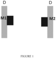
- the magnets are co-axially oriented on the doorway such that the direction of the magnetic field created across the doorway is from the North Pole of a first magnet to the South Pole of a second magnet.
- the communications unit is a smartphone and the unique identification is the IMEI (International Mobile Equipment Identity) number of the smartphone.
- IMEI International Mobile Equipment Identity
- the communications unit is on the body of the subject in a position corresponding to positive Y-axis of the communications unit being oriented towards the ventral half of the coronal plane of the subject.
- the vector determination module may comprise:
- the server implements:
- the display module may further comprise a user interface, and the comparator module, in the event of detecting the anomaly, enables a user to view the video footage of the moving subject passing through the doorway on the display unit and manually correct the anomaly through the user interface.
- system may further comprise a location detection system to detect the location of the doorway through which said subject passes.
- the location detection system is selected from the group consisting of an RFID system and a GPS tracking system.
- the step of determining the gravitational vector may include the following steps:
- the step of determining the corrected magnetic field vector may include the following steps:
- the method may further comprise the following steps:
- the step of comparing the received data may include the step of enabling a user to view a video footage of the moving subject passing through the doorway, in the event of detecting the anomaly and manually correcting the anomaly.
- the present disclosure envisages a detection system for detecting the presence and direction of a subject passing through a doorway.
- the system of the present disclosure uses magnets disposed on the doorway and a magnetometer to detect the direction of the subject. Unlike RF antennas, the magnetometer cannot be switched-off and moreover, the system does not suffer from any regulatory compliance issues.
- the detection system comprises magnets disposed on a doorway, a communication device and a server.
- the magnets are permanent magnets and the communication device is a smartphone having at least a processor, a magnetometer and a transmitter.
- the magnets are electromagnets.
- the system of the present disclosure automates the process of detecting entry/exit of smartphones into a premises. This result of detection is communicated to the server.
- the system can also be used in a disconnected manner wherein the system takes a decision offline.
- the method employed by the system determines a "relative peak" which may even be inverted.
- the method employed by the system includes a peak detection method which uses relative measures.
- the relative measure will always provide indication of a homogeneous magnetic field which is much greater than an ambient magnetic field of earth, ferrite materials or even electronic gadgets in the vicinity of the magnets disposed on the doorway.
- the system gives a clear indication of whether a subject with the smartphone has entered/exited the premises.
- Magnets M1 and M2 are co-axially positioned on the doorway (D) such that the North Pole of magnet M1 and the South Pole of magnet M2 points outwards. This creates a magnetic field across the doorway.
- the direction of the net magnetic field (including the ambient field) created across the doorway is approximately from M1 to M2.
- the magnetometer in the smartphone senses perturbations caused by the magnetic field and generates signals corresponding to the sensed perturbations.
- the processor of the smartphone cooperates with the magnetometer and processes the signals generated by the magnetometer to detect the presence of the smartphone and the direction of the smartphone and thereby the presence and direction related to entry/exit of the subject through the doorway.
- the processor generates data related to the presence and direction of the smartphone and thereby the presence and direction related to entry/exit of the subject through the doorway, the location of the doorway, and a unique identification associated with the smartphone.
- the unique identification is the IMEI (International Mobile Equipment Identity) number of the smartphone.
- the transmitter wirelessly transmits the data to the server which is remotely located from the doorway and in communication with the smartphone.
- the data received by the server relates to the presence and direction of the subject through the doorway and the unique identification.
- the processor of the smartphone implements a peak detection module, a validating module, a vector determination module and a direction detection module.
- the peak detection module detects a peak signal from the signals generated by the magnetometer.
- the validating module validates the detected peak signal.
- the vector determination module determines a gravitational vector based on signals generated by a three-axis accelerometer of the smartphone and the validated peak signal, and further determines a corrected magnetic field vector based on a vector corresponding to the magnetic field across the doorway and an ambient field vector.
- the vector determination module may comprise a low pass filter module, an averaging module and a subtractor module.
- the low pass filter module filters signals generated by the accelerometer, wherein signals generated by the accelerometer at the same time instant of the detected peak signal are filtered.
- the averaging module calculates mean of the filtered signals in X, Y and Z axes and further calculates summation of the mean of the filtered signals in X, Y and Z axes to determine the gravitational vector.
- the subtractor module subtracts the ambient field vector from the vector corresponding to the magnetic field across the access means to determine the corrected magnetic field vector.
- the direction detection module detects the direction of the smartphone and thereby the subject through the doorway based on the gravitational vector and the corrected magnetic field vector and generates data corresponding to the detected presence and direction of the subject.
- the server implements a comparator module and a display module.
- the comparator module compares the received data with a previously received data to detect an anomaly in the received data. Furthermore the comparator module, in the event of detecting the anomaly, further compares the received data with data corresponding to a video footage of the subject passing through the doorway and corrects the anomaly.
- the display module cooperates with the comparator module to display the direction of the subject based on the received data and the anomaly, if any, on a display unit of the server.
- the video footage is typically obtained from a CCTV camera installed at the doorway.
- display module comprises a user interface whereby the comparator module, in the event of detecting the anomaly, enables a user to view the video footage of the subject passing through the doorway on the display unit and manually correct the anomaly through the user interface.
- the detection system of the present disclosure is augmented by a location detection system to detect the location of each doorway through which the subject passes in a premises having a plurality of doorways.
- the location detection system comprises an RFID system.
- the server checks RFID readers located at multiple doorways within the premises to detect the location of each doorway through which the subject passes.
- the smartphone on the body of the subject includes an RFID tag which is detected by the RFID reader to detect the location of each doorway through which the subject passes.
- the location detection system comprises a GPS tracking system.
- the server checks the GPS tracking system to detect the location of the smartphone by detecting the telephone number or the unique identification of the smartphone.
- a database in the server comprises the GPS co-ordinates of gross location around the premises, whereby the smartphone is tracked to detect the location of the subject.
- the server of the system upon detecting an anomaly, activates the GPS tracking system and/or the RFID system to detect the location of the subject and correct the anomaly.
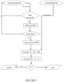
- FIG 2 a flow chart depicting the steps involved in a method of detecting a subject passing through a doorway in accordance with an embodiment .
- the method is employed by the detection system.
- the smartphone is on the body of the subject in a position such that the positive Y-axis of the smartphone always points in the ventral half of the subject's coronal plane while the subject passes through the doorway.
- the vector pointing towards user direction is denoted by U .
- the direction of the subject can be obtained from techniques known in the art such as GPS, WiFi tracking or phone inertial sensors.
- the magnetic field created across the doorway generates a relatively high magnitude peak signal than the signals from the ambient magnetic field.
- the detected peak signal is validated by the validating module by employing a cell-averaging CFAR (Constant False Alarm Rate) method, wherein the number of guard cells, N G , and number of averaging cells, N A , depends on F S .
- N G F S / 5
- N A F S / 2.
- T P the time instant when the peak signal is detected
- S P the related specific signal
- the vector determination module determines a gravitational vector which is a vector pointing towards the gravity, G and the corrected magnetic field vector, M c .
- the three-axis accelerometer embedded in the smartphone is used. Firstly, a low-pass filter with a specific cutoff frequency is applied to the accelerometer signals near the signals which are around the same time instant, T N , when the peak signal was detected.
- the low pass filter module of the vector determination module filters F S / 10 samples from ⁇ S P - ( F S /10 - 1) ⁇ to ⁇ S P ⁇ .
- the averaging module calculates mean of the filtered samples in all the three axis, denoted by g x , g y and g z .
- the magnetic field as mentioned herein above is approximately from M1 to M2 (as in the setup illustrated in Figure 1 ). This field also includes the effect of the ambient field, which needs to be removed.
- the observed magnetic field vector, measured directly from magnetometer signals is denoted by M o .
- the direction determination module makes the decision based on U whether the user has moved in or out of the gate as shown in figure 2 , where ⁇ denotes vector cross product and - denotes vector dot product.
- the method employed by the detection system of the present disclosure for detecting a subject passing through a doorway comprises the following steps:
- the method as mentioned herein above includes the following steps:
- the detection system of the present disclosure detects the entry/exit of subjects without the need for extensive infrastructure, consumes less and at the same time is cost effective.
- the technical advancements offered by the detection system of the present disclosure includes the realization of:
Landscapes
- Physics & Mathematics (AREA)
- General Physics & Mathematics (AREA)
- Computer Networks & Wireless Communication (AREA)
- Business, Economics & Management (AREA)
- Emergency Management (AREA)
- Electromagnetism (AREA)
- Engineering & Computer Science (AREA)
- Alarm Systems (AREA)
- Geophysics And Detection Of Objects (AREA)
- Mobile Radio Communication Systems (AREA)
- Measuring Magnetic Variables (AREA)
- Indicating Or Recording The Presence, Absence, Or Direction Of Movement (AREA)
- Time Recorders, Dirve Recorders, Access Control (AREA)
- Burglar Alarm Systems (AREA)
- Navigation (AREA)
- Position Fixing By Use Of Radio Waves (AREA)
Applications Claiming Priority (1)
| Application Number | Priority Date | Filing Date | Title |
|---|---|---|---|
| IN111MU2014 | 2014-01-13 |
Publications (2)
| Publication Number | Publication Date |
|---|---|
| EP2894610A1 EP2894610A1 (en) | 2015-07-15 |
| EP2894610B1 true EP2894610B1 (en) | 2023-05-10 |
Family
ID=52347175
Family Applications (1)
| Application Number | Title | Priority Date | Filing Date |
|---|---|---|---|
| EP15150958.5A Active EP2894610B1 (en) | 2014-01-13 | 2015-01-13 | A detection system |
Country Status (7)
| Country | Link |
|---|---|
| US (1) | US9613511B2 (enExample) |
| EP (1) | EP2894610B1 (enExample) |
| JP (1) | JP6320308B2 (enExample) |
| KR (1) | KR102158886B1 (enExample) |
| CN (1) | CN104777515B (enExample) |
| AU (1) | AU2015200145B2 (enExample) |
| ZA (1) | ZA201500063B (enExample) |
Families Citing this family (9)
| Publication number | Priority date | Publication date | Assignee | Title |
|---|---|---|---|---|
| US20170180464A1 (en) * | 2012-04-05 | 2017-06-22 | Blis Media Limited | Evaluating The Efficacy Of An Advertisement Campaign |
| CN105334481A (zh) * | 2015-09-02 | 2016-02-17 | 哈尔滨飞机工业集团有限责任公司 | 一种磁强计有效性监控方法 |
| HK1204847A2 (en) * | 2015-09-16 | 2015-12-04 | 英基科技有限公司 | A time card punching system |
| EP3398174B1 (en) * | 2015-12-31 | 2019-09-11 | Robert Bosch GmbH | Window sensing device with movement detection |
| EP3261060B1 (de) * | 2016-06-24 | 2021-08-04 | Skidata Ag | Verfahren zur zugangskontrolle bei einem zugangskontrollsystem für personen oder fahrzeuge sowie zugangskontrollsystem |
| CN108389291A (zh) * | 2018-02-28 | 2018-08-10 | 郭志彪 | 一种基于磁场感应的门禁系统、控制方法及其装置 |
| KR102656655B1 (ko) | 2018-08-16 | 2024-04-12 | 삼성전자 주식회사 | 외부 전자 장치의 이동 방향에 기반하여 동작을 수행하는 전자 장치 및 전자 장치의 동작 방법 |
| KR102674973B1 (ko) | 2018-12-07 | 2024-06-14 | 삼성전자주식회사 | 사용자의 위치를 감지하기 위한 전자 장치 및 그에 관한 방법 |
| KR102636447B1 (ko) * | 2022-11-14 | 2024-02-13 | 주식회사 티머니 | 태그리스 결제를 위한 검표 정확성 향상 방법 및 버스의 앞뒷문 승하차 구분 방법 및 이를 위한 시스템 |
Family Cites Families (19)
| Publication number | Priority date | Publication date | Assignee | Title |
|---|---|---|---|---|
| FR2270604B1 (enExample) | 1974-05-06 | 1976-12-17 | France Etat | |
| GB2395276B (en) * | 2002-11-12 | 2006-03-08 | Qinetiq Ltd | Ferromagnetic object detector |
| FR2856800B1 (fr) | 2003-06-24 | 2005-12-09 | Magnetic Soft | Procede de calcul du champ magnetique genere par un systeme materiel et dispositif de mise en oeuvre d'un tel procede de calcul |
| US20050237197A1 (en) * | 2004-04-23 | 2005-10-27 | Liebermann Howard H | Detection of articles having substantially rectangular cross-sections |
| JP4380753B2 (ja) * | 2007-09-19 | 2009-12-09 | 富士ゼロックス株式会社 | 携行物管理ゲート |
| US7994773B2 (en) | 2008-07-11 | 2011-08-09 | Data Security, Inc. | Apparatus and method for in-field magnetic measurements |
| CN102164532B (zh) * | 2008-09-23 | 2014-10-15 | 皇家飞利浦电子股份有限公司 | 功率测量方法和装置 |
| FR2950151B1 (fr) * | 2009-09-15 | 2011-10-21 | Commissariat Energie Atomique | Procede et systeme de localisation d'une personne, support d'enregistrement pour ce procede |
| AU2010306542B2 (en) | 2009-10-16 | 2015-09-03 | Emprimus, Llc | Electromagnetic field detection systems |
| CN102741653B (zh) * | 2009-11-24 | 2016-11-09 | 诺基亚技术有限公司 | 安装磁信号源以便定位 |
| DE102009057258A1 (de) | 2009-12-08 | 2011-06-09 | Embex Gmbh | Magnetfeldsensor und Verfahren zur Messung der horizontalen Komponente eines Magnetfelds |
| US9224021B2 (en) * | 2011-02-18 | 2015-12-29 | Checkpoint Systems, Inc. | Point of entry deactivation |
| US20120221695A1 (en) * | 2011-02-28 | 2012-08-30 | Scott Douglas Rose | Methods and apparatus to integrate logical and physical access control |
| DE102011050926A1 (de) * | 2011-06-08 | 2012-12-13 | Humotion Gmbh | System zur Erfassung der Position eines Gegenstandes |
| JP5926956B2 (ja) * | 2011-12-29 | 2016-05-25 | キロニー産業株式会社 | 情報処理システム |
| JP5987538B2 (ja) * | 2012-08-03 | 2016-09-07 | 株式会社リコー | 制御装置、プログラムおよび制御システム |
| JP2014075964A (ja) * | 2012-09-11 | 2014-04-24 | Ricoh Co Ltd | 種類判定装置、種類判定方法およびプログラム |
| US9398287B2 (en) * | 2013-02-28 | 2016-07-19 | Google Technology Holdings LLC | Context-based depth sensor control |
| JP6024630B2 (ja) * | 2013-09-19 | 2016-11-16 | 三菱電機株式会社 | 集中管理装置、人体位置検出システム、及び機器制御システム |
-
2015
- 2015-01-06 US US14/590,522 patent/US9613511B2/en active Active
- 2015-01-06 ZA ZA2015/00063A patent/ZA201500063B/en unknown
- 2015-01-08 JP JP2015002175A patent/JP6320308B2/ja active Active
- 2015-01-08 CN CN201510008482.XA patent/CN104777515B/zh active Active
- 2015-01-13 EP EP15150958.5A patent/EP2894610B1/en active Active
- 2015-01-13 AU AU2015200145A patent/AU2015200145B2/en active Active
- 2015-01-13 KR KR1020150005890A patent/KR102158886B1/ko active Active
Also Published As
| Publication number | Publication date |
|---|---|
| KR102158886B1 (ko) | 2020-09-22 |
| US9613511B2 (en) | 2017-04-04 |
| EP2894610A1 (en) | 2015-07-15 |
| JP6320308B2 (ja) | 2018-05-09 |
| CN104777515B (zh) | 2018-09-07 |
| US20150199889A1 (en) | 2015-07-16 |
| CN104777515A (zh) | 2015-07-15 |
| JP2015132602A (ja) | 2015-07-23 |
| AU2015200145B2 (en) | 2020-02-06 |
| KR20150084673A (ko) | 2015-07-22 |
| ZA201500063B (en) | 2015-12-23 |
| AU2015200145A1 (en) | 2015-07-30 |
Similar Documents
| Publication | Publication Date | Title |
|---|---|---|
| EP2894610B1 (en) | A detection system | |
| US9599473B2 (en) | Utilizing magnetic field based navigation | |
| KR101550302B1 (ko) | 비콘신호와 스마트 단말기를 이용한 위치 추적 장치 및 방법 | |
| EP3281020B1 (en) | Opportunistic calibration of a smartphone orientation in a vehicle | |
| KR20120013446A (ko) | 기초 무브먼트 패턴 평가에 의한 무브먼트 검출을 위한 방법 및 장치 | |
| US20160350811A1 (en) | Measurements of earth's magnetic field indoors | |
| EP3492868B1 (en) | Mobile device localization based on spatial derivative magnetic fingerprint | |
| WO2016011507A1 (en) | Monitoring system, device, method, processing system, fall arrest equipment and kit for use with a fall arrest system | |
| JP2015132602A5 (enExample) | ||
| US10157533B2 (en) | Tracking device and a system for finding objects | |
| US9742475B2 (en) | Proximity beacon | |
| US10175777B2 (en) | Method and apparatus for detecting a manipulation of a portable device | |
| WO2018075531A8 (en) | SYSTEMS, DEVICES AND METHODS FOR MONITORING OBJECTS IN A CART | |
| CA3070709C (en) | Method and system for threshold-based detection of distortive magnetic fields in indoor locations | |
| JP6282960B2 (ja) | 情報プッシュ方法および装置 | |
| US20220326342A1 (en) | Use of visible light signals for determining one or more parameters for presence detection | |
| JP2020183921A (ja) | 位置情報提供装置、方法、及びプログラム | |
| US20190065984A1 (en) | Method and electronic device for detecting and recognizing autonomous gestures in a monitored location | |
| Yoon et al. | Forward‐backward approach for 3D event localization using commodity smartphones for ubiquitous context‐aware applications in civil and infrastructure engineering | |
| Vasylenko et al. | Individual Mobile Navigation System of Way Counting | |
| CN105719153A (zh) | 室内地球磁场测量 | |
| CN105512701A (zh) | 一种贵重物品管理系统 |
Legal Events
| Date | Code | Title | Description |
|---|---|---|---|
| PUAI | Public reference made under article 153(3) epc to a published international application that has entered the european phase |
Free format text: ORIGINAL CODE: 0009012 |
|
| 17P | Request for examination filed |
Effective date: 20150113 |
|
| AK | Designated contracting states |
Kind code of ref document: A1 Designated state(s): AL AT BE BG CH CY CZ DE DK EE ES FI FR GB GR HR HU IE IS IT LI LT LU LV MC MK MT NL NO PL PT RO RS SE SI SK SM TR |
|
| AX | Request for extension of the european patent |
Extension state: BA ME |
|
| R17P | Request for examination filed (corrected) |
Effective date: 20160115 |
|
| RBV | Designated contracting states (corrected) |
Designated state(s): AL AT BE BG CH CY CZ DE DK EE ES FI FR GB GR HR HU IE IS IT LI LT LU LV MC MK MT NL NO PL PT RO RS SE SI SK SM TR |
|
| RIC1 | Information provided on ipc code assigned before grant |
Ipc: G07C 9/00 20060101AFI20190520BHEP |
|
| STAA | Information on the status of an ep patent application or granted ep patent |
Free format text: STATUS: EXAMINATION IS IN PROGRESS |
|
| 17Q | First examination report despatched |
Effective date: 20190702 |
|
| RIC1 | Information provided on ipc code assigned before grant |
Ipc: G07C 9/28 20200101ALI20221208BHEP Ipc: G07C 9/00 20060101AFI20221208BHEP |
|
| GRAP | Despatch of communication of intention to grant a patent |
Free format text: ORIGINAL CODE: EPIDOSNIGR1 |
|
| STAA | Information on the status of an ep patent application or granted ep patent |
Free format text: STATUS: GRANT OF PATENT IS INTENDED |
|
| INTG | Intention to grant announced |
Effective date: 20230118 |
|
| GRAS | Grant fee paid |
Free format text: ORIGINAL CODE: EPIDOSNIGR3 |
|
| GRAA | (expected) grant |
Free format text: ORIGINAL CODE: 0009210 |
|
| STAA | Information on the status of an ep patent application or granted ep patent |
Free format text: STATUS: THE PATENT HAS BEEN GRANTED |
|
| AK | Designated contracting states |
Kind code of ref document: B1 Designated state(s): AL AT BE BG CH CY CZ DE DK EE ES FI FR GB GR HR HU IE IS IT LI LT LU LV MC MK MT NL NO PL PT RO RS SE SI SK SM TR |
|
| REG | Reference to a national code |
Ref country code: GB Ref legal event code: FG4D |
|
| REG | Reference to a national code |
Ref country code: AT Ref legal event code: REF Ref document number: 1567477 Country of ref document: AT Kind code of ref document: T Effective date: 20230515 Ref country code: CH Ref legal event code: EP |
|
| REG | Reference to a national code |
Ref country code: DE Ref legal event code: R096 Ref document number: 602015083486 Country of ref document: DE |
|
| REG | Reference to a national code |
Ref country code: IE Ref legal event code: FG4D |
|
| P01 | Opt-out of the competence of the unified patent court (upc) registered |
Effective date: 20230526 |
|
| REG | Reference to a national code |
Ref country code: NL Ref legal event code: FP |
|
| REG | Reference to a national code |
Ref country code: LT Ref legal event code: MG9D |
|
| REG | Reference to a national code |
Ref country code: AT Ref legal event code: MK05 Ref document number: 1567477 Country of ref document: AT Kind code of ref document: T Effective date: 20230510 |
|
| PG25 | Lapsed in a contracting state [announced via postgrant information from national office to epo] |
Ref country code: SE Free format text: LAPSE BECAUSE OF FAILURE TO SUBMIT A TRANSLATION OF THE DESCRIPTION OR TO PAY THE FEE WITHIN THE PRESCRIBED TIME-LIMIT Effective date: 20230510 Ref country code: PT Free format text: LAPSE BECAUSE OF FAILURE TO SUBMIT A TRANSLATION OF THE DESCRIPTION OR TO PAY THE FEE WITHIN THE PRESCRIBED TIME-LIMIT Effective date: 20230911 Ref country code: NO Free format text: LAPSE BECAUSE OF FAILURE TO SUBMIT A TRANSLATION OF THE DESCRIPTION OR TO PAY THE FEE WITHIN THE PRESCRIBED TIME-LIMIT Effective date: 20230810 Ref country code: ES Free format text: LAPSE BECAUSE OF FAILURE TO SUBMIT A TRANSLATION OF THE DESCRIPTION OR TO PAY THE FEE WITHIN THE PRESCRIBED TIME-LIMIT Effective date: 20230510 Ref country code: AT Free format text: LAPSE BECAUSE OF FAILURE TO SUBMIT A TRANSLATION OF THE DESCRIPTION OR TO PAY THE FEE WITHIN THE PRESCRIBED TIME-LIMIT Effective date: 20230510 |
|
| PG25 | Lapsed in a contracting state [announced via postgrant information from national office to epo] |
Ref country code: RS Free format text: LAPSE BECAUSE OF FAILURE TO SUBMIT A TRANSLATION OF THE DESCRIPTION OR TO PAY THE FEE WITHIN THE PRESCRIBED TIME-LIMIT Effective date: 20230510 Ref country code: PL Free format text: LAPSE BECAUSE OF FAILURE TO SUBMIT A TRANSLATION OF THE DESCRIPTION OR TO PAY THE FEE WITHIN THE PRESCRIBED TIME-LIMIT Effective date: 20230510 Ref country code: LV Free format text: LAPSE BECAUSE OF FAILURE TO SUBMIT A TRANSLATION OF THE DESCRIPTION OR TO PAY THE FEE WITHIN THE PRESCRIBED TIME-LIMIT Effective date: 20230510 Ref country code: LT Free format text: LAPSE BECAUSE OF FAILURE TO SUBMIT A TRANSLATION OF THE DESCRIPTION OR TO PAY THE FEE WITHIN THE PRESCRIBED TIME-LIMIT Effective date: 20230510 Ref country code: IS Free format text: LAPSE BECAUSE OF FAILURE TO SUBMIT A TRANSLATION OF THE DESCRIPTION OR TO PAY THE FEE WITHIN THE PRESCRIBED TIME-LIMIT Effective date: 20230910 Ref country code: HR Free format text: LAPSE BECAUSE OF FAILURE TO SUBMIT A TRANSLATION OF THE DESCRIPTION OR TO PAY THE FEE WITHIN THE PRESCRIBED TIME-LIMIT Effective date: 20230510 Ref country code: GR Free format text: LAPSE BECAUSE OF FAILURE TO SUBMIT A TRANSLATION OF THE DESCRIPTION OR TO PAY THE FEE WITHIN THE PRESCRIBED TIME-LIMIT Effective date: 20230811 |
|
| PG25 | Lapsed in a contracting state [announced via postgrant information from national office to epo] |
Ref country code: FI Free format text: LAPSE BECAUSE OF FAILURE TO SUBMIT A TRANSLATION OF THE DESCRIPTION OR TO PAY THE FEE WITHIN THE PRESCRIBED TIME-LIMIT Effective date: 20230510 |
|
| PG25 | Lapsed in a contracting state [announced via postgrant information from national office to epo] |
Ref country code: SK Free format text: LAPSE BECAUSE OF FAILURE TO SUBMIT A TRANSLATION OF THE DESCRIPTION OR TO PAY THE FEE WITHIN THE PRESCRIBED TIME-LIMIT Effective date: 20230510 |
|
| PG25 | Lapsed in a contracting state [announced via postgrant information from national office to epo] |
Ref country code: SM Free format text: LAPSE BECAUSE OF FAILURE TO SUBMIT A TRANSLATION OF THE DESCRIPTION OR TO PAY THE FEE WITHIN THE PRESCRIBED TIME-LIMIT Effective date: 20230510 Ref country code: SK Free format text: LAPSE BECAUSE OF FAILURE TO SUBMIT A TRANSLATION OF THE DESCRIPTION OR TO PAY THE FEE WITHIN THE PRESCRIBED TIME-LIMIT Effective date: 20230510 Ref country code: RO Free format text: LAPSE BECAUSE OF FAILURE TO SUBMIT A TRANSLATION OF THE DESCRIPTION OR TO PAY THE FEE WITHIN THE PRESCRIBED TIME-LIMIT Effective date: 20230510 Ref country code: EE Free format text: LAPSE BECAUSE OF FAILURE TO SUBMIT A TRANSLATION OF THE DESCRIPTION OR TO PAY THE FEE WITHIN THE PRESCRIBED TIME-LIMIT Effective date: 20230510 Ref country code: DK Free format text: LAPSE BECAUSE OF FAILURE TO SUBMIT A TRANSLATION OF THE DESCRIPTION OR TO PAY THE FEE WITHIN THE PRESCRIBED TIME-LIMIT Effective date: 20230510 Ref country code: CZ Free format text: LAPSE BECAUSE OF FAILURE TO SUBMIT A TRANSLATION OF THE DESCRIPTION OR TO PAY THE FEE WITHIN THE PRESCRIBED TIME-LIMIT Effective date: 20230510 |
|
| REG | Reference to a national code |
Ref country code: DE Ref legal event code: R097 Ref document number: 602015083486 Country of ref document: DE |
|
| PLBE | No opposition filed within time limit |
Free format text: ORIGINAL CODE: 0009261 |
|
| STAA | Information on the status of an ep patent application or granted ep patent |
Free format text: STATUS: NO OPPOSITION FILED WITHIN TIME LIMIT |
|
| 26N | No opposition filed |
Effective date: 20240213 |
|
| PG25 | Lapsed in a contracting state [announced via postgrant information from national office to epo] |
Ref country code: SI Free format text: LAPSE BECAUSE OF FAILURE TO SUBMIT A TRANSLATION OF THE DESCRIPTION OR TO PAY THE FEE WITHIN THE PRESCRIBED TIME-LIMIT Effective date: 20230510 |
|
| PG25 | Lapsed in a contracting state [announced via postgrant information from national office to epo] |
Ref country code: SI Free format text: LAPSE BECAUSE OF FAILURE TO SUBMIT A TRANSLATION OF THE DESCRIPTION OR TO PAY THE FEE WITHIN THE PRESCRIBED TIME-LIMIT Effective date: 20230510 Ref country code: IT Free format text: LAPSE BECAUSE OF FAILURE TO SUBMIT A TRANSLATION OF THE DESCRIPTION OR TO PAY THE FEE WITHIN THE PRESCRIBED TIME-LIMIT Effective date: 20230510 |
|
| PG25 | Lapsed in a contracting state [announced via postgrant information from national office to epo] |
Ref country code: MC Free format text: LAPSE BECAUSE OF FAILURE TO SUBMIT A TRANSLATION OF THE DESCRIPTION OR TO PAY THE FEE WITHIN THE PRESCRIBED TIME-LIMIT Effective date: 20230510 |
|
| PG25 | Lapsed in a contracting state [announced via postgrant information from national office to epo] |
Ref country code: MC Free format text: LAPSE BECAUSE OF FAILURE TO SUBMIT A TRANSLATION OF THE DESCRIPTION OR TO PAY THE FEE WITHIN THE PRESCRIBED TIME-LIMIT Effective date: 20230510 |
|
| PG25 | Lapsed in a contracting state [announced via postgrant information from national office to epo] |
Ref country code: LU Free format text: LAPSE BECAUSE OF NON-PAYMENT OF DUE FEES Effective date: 20240113 |
|
| PG25 | Lapsed in a contracting state [announced via postgrant information from national office to epo] |
Ref country code: LU Free format text: LAPSE BECAUSE OF NON-PAYMENT OF DUE FEES Effective date: 20240113 |
|
| PG25 | Lapsed in a contracting state [announced via postgrant information from national office to epo] |
Ref country code: BE Free format text: LAPSE BECAUSE OF NON-PAYMENT OF DUE FEES Effective date: 20240131 |
|
| PG25 | Lapsed in a contracting state [announced via postgrant information from national office to epo] |
Ref country code: BE Free format text: LAPSE BECAUSE OF NON-PAYMENT OF DUE FEES Effective date: 20240131 |
|
| REG | Reference to a national code |
Ref country code: BE Ref legal event code: MM Effective date: 20240131 |
|
| PG25 | Lapsed in a contracting state [announced via postgrant information from national office to epo] |
Ref country code: BG Free format text: LAPSE BECAUSE OF FAILURE TO SUBMIT A TRANSLATION OF THE DESCRIPTION OR TO PAY THE FEE WITHIN THE PRESCRIBED TIME-LIMIT Effective date: 20230510 |
|
| PG25 | Lapsed in a contracting state [announced via postgrant information from national office to epo] |
Ref country code: BG Free format text: LAPSE BECAUSE OF FAILURE TO SUBMIT A TRANSLATION OF THE DESCRIPTION OR TO PAY THE FEE WITHIN THE PRESCRIBED TIME-LIMIT Effective date: 20230510 |
|
| PG25 | Lapsed in a contracting state [announced via postgrant information from national office to epo] |
Ref country code: IE Free format text: LAPSE BECAUSE OF NON-PAYMENT OF DUE FEES Effective date: 20240113 |
|
| PG25 | Lapsed in a contracting state [announced via postgrant information from national office to epo] |
Ref country code: IE Free format text: LAPSE BECAUSE OF NON-PAYMENT OF DUE FEES Effective date: 20240113 |
|
| PGFP | Annual fee paid to national office [announced via postgrant information from national office to epo] |
Ref country code: NL Payment date: 20250127 Year of fee payment: 11 |
|
| PGFP | Annual fee paid to national office [announced via postgrant information from national office to epo] |
Ref country code: DE Payment date: 20250121 Year of fee payment: 11 |
|
| PGFP | Annual fee paid to national office [announced via postgrant information from national office to epo] |
Ref country code: CH Payment date: 20250201 Year of fee payment: 11 |
|
| PGFP | Annual fee paid to national office [announced via postgrant information from national office to epo] |
Ref country code: FR Payment date: 20250121 Year of fee payment: 11 |
|
| PGFP | Annual fee paid to national office [announced via postgrant information from national office to epo] |
Ref country code: GB Payment date: 20250124 Year of fee payment: 11 |
|
| PG25 | Lapsed in a contracting state [announced via postgrant information from national office to epo] |
Ref country code: CY Free format text: LAPSE BECAUSE OF FAILURE TO SUBMIT A TRANSLATION OF THE DESCRIPTION OR TO PAY THE FEE WITHIN THE PRESCRIBED TIME-LIMIT; INVALID AB INITIO Effective date: 20150113 |
|
| PG25 | Lapsed in a contracting state [announced via postgrant information from national office to epo] |
Ref country code: HU Free format text: LAPSE BECAUSE OF FAILURE TO SUBMIT A TRANSLATION OF THE DESCRIPTION OR TO PAY THE FEE WITHIN THE PRESCRIBED TIME-LIMIT; INVALID AB INITIO Effective date: 20150113 |