EP2894410A1 - Air conditioning device - Google Patents
Air conditioning device Download PDFInfo
- Publication number
- EP2894410A1 EP2894410A1 EP12882657.5A EP12882657A EP2894410A1 EP 2894410 A1 EP2894410 A1 EP 2894410A1 EP 12882657 A EP12882657 A EP 12882657A EP 2894410 A1 EP2894410 A1 EP 2894410A1
- Authority
- EP
- European Patent Office
- Prior art keywords
- side refrigerant
- heat exchanger
- indoor
- convective
- radiant
- Prior art date
- Legal status (The legal status is an assumption and is not a legal conclusion. Google has not performed a legal analysis and makes no representation as to the accuracy of the status listed.)
- Granted
Links
Images






Classifications
-
- F—MECHANICAL ENGINEERING; LIGHTING; HEATING; WEAPONS; BLASTING
- F24—HEATING; RANGES; VENTILATING
- F24F—AIR-CONDITIONING; AIR-HUMIDIFICATION; VENTILATION; USE OF AIR CURRENTS FOR SCREENING
- F24F3/00—Air-conditioning systems in which conditioned primary air is supplied from one or more central stations to distributing units in the rooms or spaces where it may receive secondary treatment; Apparatus specially designed for such systems
- F24F3/06—Air-conditioning systems in which conditioned primary air is supplied from one or more central stations to distributing units in the rooms or spaces where it may receive secondary treatment; Apparatus specially designed for such systems characterised by the arrangements for the supply of heat-exchange fluid for the subsequent treatment of primary air in the room units
- F24F3/065—Air-conditioning systems in which conditioned primary air is supplied from one or more central stations to distributing units in the rooms or spaces where it may receive secondary treatment; Apparatus specially designed for such systems characterised by the arrangements for the supply of heat-exchange fluid for the subsequent treatment of primary air in the room units with a plurality of evaporators or condensers
-
- F—MECHANICAL ENGINEERING; LIGHTING; HEATING; WEAPONS; BLASTING
- F25—REFRIGERATION OR COOLING; COMBINED HEATING AND REFRIGERATION SYSTEMS; HEAT PUMP SYSTEMS; MANUFACTURE OR STORAGE OF ICE; LIQUEFACTION SOLIDIFICATION OF GASES
- F25B—REFRIGERATION MACHINES, PLANTS OR SYSTEMS; COMBINED HEATING AND REFRIGERATION SYSTEMS; HEAT PUMP SYSTEMS
- F25B13/00—Compression machines, plants or systems, with reversible cycle
-
- F—MECHANICAL ENGINEERING; LIGHTING; HEATING; WEAPONS; BLASTING
- F25—REFRIGERATION OR COOLING; COMBINED HEATING AND REFRIGERATION SYSTEMS; HEAT PUMP SYSTEMS; MANUFACTURE OR STORAGE OF ICE; LIQUEFACTION SOLIDIFICATION OF GASES
- F25B—REFRIGERATION MACHINES, PLANTS OR SYSTEMS; COMBINED HEATING AND REFRIGERATION SYSTEMS; HEAT PUMP SYSTEMS
- F25B30/00—Heat pumps
- F25B30/02—Heat pumps of the compression type
-
- F—MECHANICAL ENGINEERING; LIGHTING; HEATING; WEAPONS; BLASTING
- F25—REFRIGERATION OR COOLING; COMBINED HEATING AND REFRIGERATION SYSTEMS; HEAT PUMP SYSTEMS; MANUFACTURE OR STORAGE OF ICE; LIQUEFACTION SOLIDIFICATION OF GASES
- F25B—REFRIGERATION MACHINES, PLANTS OR SYSTEMS; COMBINED HEATING AND REFRIGERATION SYSTEMS; HEAT PUMP SYSTEMS
- F25B49/00—Arrangement or mounting of control or safety devices
- F25B49/02—Arrangement or mounting of control or safety devices for compression type machines, plants or systems
-
- F—MECHANICAL ENGINEERING; LIGHTING; HEATING; WEAPONS; BLASTING
- F25—REFRIGERATION OR COOLING; COMBINED HEATING AND REFRIGERATION SYSTEMS; HEAT PUMP SYSTEMS; MANUFACTURE OR STORAGE OF ICE; LIQUEFACTION SOLIDIFICATION OF GASES
- F25B—REFRIGERATION MACHINES, PLANTS OR SYSTEMS; COMBINED HEATING AND REFRIGERATION SYSTEMS; HEAT PUMP SYSTEMS
- F25B2313/00—Compression machines, plants or systems with reversible cycle not otherwise provided for
- F25B2313/003—Indoor unit with water as a heat sink or heat source
-
- F—MECHANICAL ENGINEERING; LIGHTING; HEATING; WEAPONS; BLASTING
- F25—REFRIGERATION OR COOLING; COMBINED HEATING AND REFRIGERATION SYSTEMS; HEAT PUMP SYSTEMS; MANUFACTURE OR STORAGE OF ICE; LIQUEFACTION SOLIDIFICATION OF GASES
- F25B—REFRIGERATION MACHINES, PLANTS OR SYSTEMS; COMBINED HEATING AND REFRIGERATION SYSTEMS; HEAT PUMP SYSTEMS
- F25B2313/00—Compression machines, plants or systems with reversible cycle not otherwise provided for
- F25B2313/006—Compression machines, plants or systems with reversible cycle not otherwise provided for two pipes connecting the outdoor side to the indoor side with multiple indoor units
-
- F—MECHANICAL ENGINEERING; LIGHTING; HEATING; WEAPONS; BLASTING
- F25—REFRIGERATION OR COOLING; COMBINED HEATING AND REFRIGERATION SYSTEMS; HEAT PUMP SYSTEMS; MANUFACTURE OR STORAGE OF ICE; LIQUEFACTION SOLIDIFICATION OF GASES
- F25B—REFRIGERATION MACHINES, PLANTS OR SYSTEMS; COMBINED HEATING AND REFRIGERATION SYSTEMS; HEAT PUMP SYSTEMS
- F25B2313/00—Compression machines, plants or systems with reversible cycle not otherwise provided for
- F25B2313/023—Compression machines, plants or systems with reversible cycle not otherwise provided for using multiple indoor units
- F25B2313/0231—Compression machines, plants or systems with reversible cycle not otherwise provided for using multiple indoor units with simultaneous cooling and heating
-
- F—MECHANICAL ENGINEERING; LIGHTING; HEATING; WEAPONS; BLASTING
- F25—REFRIGERATION OR COOLING; COMBINED HEATING AND REFRIGERATION SYSTEMS; HEAT PUMP SYSTEMS; MANUFACTURE OR STORAGE OF ICE; LIQUEFACTION SOLIDIFICATION OF GASES
- F25B—REFRIGERATION MACHINES, PLANTS OR SYSTEMS; COMBINED HEATING AND REFRIGERATION SYSTEMS; HEAT PUMP SYSTEMS
- F25B2313/00—Compression machines, plants or systems with reversible cycle not otherwise provided for
- F25B2313/023—Compression machines, plants or systems with reversible cycle not otherwise provided for using multiple indoor units
- F25B2313/0233—Compression machines, plants or systems with reversible cycle not otherwise provided for using multiple indoor units in parallel arrangements
-
- F—MECHANICAL ENGINEERING; LIGHTING; HEATING; WEAPONS; BLASTING
- F25—REFRIGERATION OR COOLING; COMBINED HEATING AND REFRIGERATION SYSTEMS; HEAT PUMP SYSTEMS; MANUFACTURE OR STORAGE OF ICE; LIQUEFACTION SOLIDIFICATION OF GASES
- F25B—REFRIGERATION MACHINES, PLANTS OR SYSTEMS; COMBINED HEATING AND REFRIGERATION SYSTEMS; HEAT PUMP SYSTEMS
- F25B2313/00—Compression machines, plants or systems with reversible cycle not otherwise provided for
- F25B2313/023—Compression machines, plants or systems with reversible cycle not otherwise provided for using multiple indoor units
- F25B2313/0234—Compression machines, plants or systems with reversible cycle not otherwise provided for using multiple indoor units in series arrangements
-
- F—MECHANICAL ENGINEERING; LIGHTING; HEATING; WEAPONS; BLASTING
- F25—REFRIGERATION OR COOLING; COMBINED HEATING AND REFRIGERATION SYSTEMS; HEAT PUMP SYSTEMS; MANUFACTURE OR STORAGE OF ICE; LIQUEFACTION SOLIDIFICATION OF GASES
- F25B—REFRIGERATION MACHINES, PLANTS OR SYSTEMS; COMBINED HEATING AND REFRIGERATION SYSTEMS; HEAT PUMP SYSTEMS
- F25B2313/00—Compression machines, plants or systems with reversible cycle not otherwise provided for
- F25B2313/027—Compression machines, plants or systems with reversible cycle not otherwise provided for characterised by the reversing means
- F25B2313/0272—Compression machines, plants or systems with reversible cycle not otherwise provided for characterised by the reversing means using bridge circuits of one-way valves
-
- F—MECHANICAL ENGINEERING; LIGHTING; HEATING; WEAPONS; BLASTING
- F25—REFRIGERATION OR COOLING; COMBINED HEATING AND REFRIGERATION SYSTEMS; HEAT PUMP SYSTEMS; MANUFACTURE OR STORAGE OF ICE; LIQUEFACTION SOLIDIFICATION OF GASES
- F25B—REFRIGERATION MACHINES, PLANTS OR SYSTEMS; COMBINED HEATING AND REFRIGERATION SYSTEMS; HEAT PUMP SYSTEMS
- F25B2313/00—Compression machines, plants or systems with reversible cycle not otherwise provided for
- F25B2313/027—Compression machines, plants or systems with reversible cycle not otherwise provided for characterised by the reversing means
- F25B2313/02741—Compression machines, plants or systems with reversible cycle not otherwise provided for characterised by the reversing means using one four-way valve
Definitions
- the present invention relates to an air-conditioning apparatus including a plurality of indoor units and capable of heating and cooling at the same time, such as a multi-air-conditioning apparatus for a building.
- Indoor units in air-conditioning apparatuses placed in buildings, houses, or the like can use a convective (air-sending type) heat exchanger for forcibly exchanging heat using an blower device and a radiant (panel) heat exchanger for exchanging heat by natural convection without sending air using an blower device.
- a convective (air-sending type) heat exchanger for forcibly exchanging heat using an blower device
- a radiant (panel) heat exchanger for exchanging heat by natural convection without sending air using an blower device.
- the convective heat exchanger can perform quick cooling, but may cause a person to feel uncomfortable or the like by directly sending air.
- the radiant indoor heat exchanger can perform heating and cooling operation without directly sending air, but cannot perform rapid heating and cooling operation.
- An air-conditioning system including both the radiant panel heat exchanger and the convective heat exchanger has been proposed (see, for example, Patent Literature 1).
- Patent Literature 1 discloses an air-conditioning system that has a configuration in which the radiant panel heat exchanger is arranged on the floor side, the convective heat exchanger is arranged on the ceiling side, and the radiant panel heat exchanger and convective heat exchanger are connected in series and that circulates a refrigerant.
- An air-conditioning apparatus that does not have a configuration in which an outdoor unit and indoor units are not directly connected so as to allow a refrigerant to flow therebetween but has a configuration in which it includes a first-side refrigerant circuit and a second-side refrigerant circuit and exchanges heat therebetween using an intermediate heat exchanger has been proposed (see, for example, Patent Literature 2).
- the air-conditioning apparatus described in Patent Literature 2 is operable principally in four operation modes of cooling only operation, heating only operation, heating main operation, and cooling main operation and can individually set the operation mode for each indoor unit using a convective heat exchanger including an blower device in accordance with the situation of the room or the like.
- Patent Literature 1 discloses an air-conditioning system in which a single radiant panel heat exchanging portion and a single air-sending heat exchanging portion are connected. To perform heating and cooling operation for the entire structure of a building or the like, a plurality of indoor units, as illustrated in Patent Literature 2, are necessary. Not only in the case where the convective heat exchanger is used, as illustrated in Patent Literature 2, but also in the case where the radiant panel heat exchanger is used, it is desired that the indoor units be appropriately arranged and comfortable air-conditioning matching with the situation or the like of a room be provided.
- the present invention has been made to overcome the above-described problems. It is an object of the present invention to provide an air-conditioning apparatus capable of performing comfortable air-conditioning in accordance with the uses and arrangement of rooms inside a structure of a building or the like.
- An air-conditioning apparatus includes an outdoor unit including a compressor configured to compress a first-side refrigerant and a heat-source-side heat exchanger configured to cause heat exchange between air and the first-side refrigerant, a plurality of indoor units including indoor heat exchangers configured to cause heat exchange between the air and a second-side refrigerant, a plurality of intermediate heat exchangers configured to cause heat exchange between the first-side refrigerant and the second-side refrigerant, the intermediate heat exchangers being connected to the outdoor unit by a first-side refrigerant pipe and connected to the indoor units by a second-side refrigerant pipe, and a flow switching device configured to switch combination of connection between each of the indoor units and each of the intermediate heat exchangers.
- the plurality of indoor units include convective indoor units and radiant indoor units, each of the convective indoor units includes a convective indoor heat exchanger, and each of the radiant indoor units includes a radiant indoor heat exchanger.
- the air-conditioning apparatus is an air-conditioning system including indoor units including convective heat exchangers and radiant indoor heat exchangers.
- This air-conditioning apparatus can perform air-conditioning in accordance with the use and load of each room, while at the same time greater space and energy savings are achieved, in comparison with cases where both a convective air-conditioning system and a radiant air-conditioning system are installed.
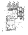
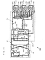
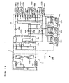
- FIG. 1 is a refrigerant circuit diagram that illustrates Embodiment 1 of an air-conditioning apparatus of the present invention.
- an air-conditioning apparatus 1 when it is considered in units, it includes an outdoor unit 1A being a heat source device, a plurality of indoor units C1n and C2m (hereinafter referred to simply as indoor units C when they are referred to without distinction), and an intermediate unit 1B.
- the letters m and n are natural numbers more than zero, m indicates the number of radiant indoor heat exchangers, and n indicates the number of convective indoor heat exchangers.
- Embodiment 1 the case where m is three and n is three is illustrated.
- the outdoor unit 1A and intermediate unit 1B are connected by a first refrigerant pipe.
- the intermediate unit 1B and each of the plurality of indoor units C are connected by a second refrigerant pipe. Cooling energy or heating energy produced by the outdoor unit 1A is conveyed to the indoor units C1n and C2m through the intermediate unit 1B.
- the outdoor unit 1A is typically placed in an outside space, such as one on the roof of a building, and is configured to supply cooling energy or heating energy to the indoor units C1n and C2m through the intermediate unit 1B.
- the outdoor unit 1A includes a compressor 103, a heat-source-side heat exchanger 104, and a first flow switching device 106.
- the compressor 103 is configured to suck a first-side refrigerant in gaseous state, compress it to a high-temperature and high-pressure state, and discharge it.
- the compressor 103 may be an inverter compressor having a controllable capacity.
- the heat-source-side heat exchanger 104 functions as a radiator in cooling operation and as an evaporator in heating operation and is configured to cause heat exchange between outdoor air supplied through a fan 104a and the first-side refrigerant.
- the first flow switching device 106 may include, for example, a four-way valve and is configured to switch a flow of the first-side refrigerant in cooling operation (cooling only operation mode and cooling main operation mode) and in heating operation (heating only operation mode and heating main operation mode). Specifically, in cooling operation, the first flow switching device 106 switches the refrigerant passage such that the first-side refrigerant discharged from the compressor 103 flows into the heat-source-side heat exchanger 104 and the first-side refrigerant exiting from the intermediate unit 1B flows into the compressor 103.
- the first flow switching device 106 switches the refrigerant passage such that the first-side refrigerant discharged from the compressor 103 flows into the intermediate unit 1B and the first-side refrigerant exiting from the heat-source-side heat exchanger 104 flows into the compressor 103.
- check valves 113a to 113d each has the function of limiting the passing direction in which the first-side refrigerant passes between the outdoor unit 1A and intermediate unit 1B to a fixed direction.
- the check valve 113a is disposed on a refrigerant pipe connecting the first flow switching device 106 and valves 111c and 111d and allows the first-side refrigerant to flow in only a direction from the valves 111c and 111d toward the first flow switching device 106.
- the check valve 113b is disposed on a refrigerant pipe connecting the heat-source-side heat exchanger 104 and a valve 111e and allows the first-side refrigerant to flow in only a direction from the heat-source-side heat exchanger 104 toward the valve 111e.
- the check valve 113c is disposed on a refrigerant pipe that connects a refrigerant pipe connecting the first flow switching device 106 and the check valve 113a and a refrigerant pipe connecting the check valve 113b and the valve 111e and allows the first-side refrigerant to flow in only a direction from the side of the refrigerant pipe connecting the first flow switching device 106 and the check valve 113a toward the side of the refrigerant pipe connecting the check valve 113b and the valve 111e.
- the check valve 113d is disposed on a refrigerant pipe that connects a refrigerant pipe connecting the check valve 113a and the valves 111c and 111d and a refrigerant pipe connecting the heat-source-side heat exchanger 104 and the check valve 113b and allows the first-side refrigerant to flow in only a direction from the side of the refrigerant pipe connecting the check valve 113a and the valves 111c and 111d toward the side of the refrigerant pipe connecting the heat-source-side heat exchanger 104 and the check valve 113b.
- the intermediate unit 1B may be disposed on a location or the like different from the outdoor space and indoor space as a housing different from the outdoor unit 1A and indoor units C and is connected to the outdoor unit 1A through the first refrigerant pipe and to the indoor units C through the second refrigerant pipes.
- the intermediate unit 1B includes intermediate heat exchangers 107a and 107b, expansion mechanisms 105a and 105b, pumps 109a and 109b, and valves 111a to 111f, 112na to 112nd, 115ma to 115md, and 114a to 114d.
- the intermediate unit 1B is connected to the outdoor unit 1A by the first refrigerant pipe through the expansion mechanisms 105a and 105b and the valves 111a to 111f.
- the intermediate unit 1B is connected to each of the plurality of indoor units C, which are the indoor units C1n and C2m, through the pumps 109a and 109b and the valves 112na to 112nd, 115ma to 115dm, and 114a to 114d.
- each of the intermediate heat exchangers 107a and 107b may include a double pipe heat exchanger, plate heat exchanger, microchannel water heat exchanger, and shell and tube heat exchanger.
- Each of the intermediate heat exchangers 107a and 107b includes a refrigerant passage through which the first-side refrigerant passes and a refrigerant passage through which the second-side refrigerant passes.
- Each of the intermediate heat exchangers 107a and 107b functions as a radiator or evaporator and causes heat exchange between the first-side refrigerant and the second-side refrigerant. That is, the intermediate heat exchangers 107a and 107b cause heat exchange between the first-side refrigerant circulating in a first-side refrigerant circuit 2 and the second-side refrigerant circulating in a second-side refrigerant circuit 3.
- the intermediate heat exchanger 107a is disposed between the expansion mechanism 105a and the valve 111c on the side of the first-side refrigerant circuit 2 and between the valve 114a and the pump 109a on the side of the second-side refrigerant circuit 3.
- the intermediate heat exchanger 107b is disposed between the expansion mechanism 105b and the valve 111d on the side of the first-side refrigerant circuit 2 and between the valve 114b and the pump 109b on the side of the second-side refrigerant circuit 3.
- the intermediate heat exchangers 107a and 107b are plate heat exchangers, in consideration of phase change of the first-side refrigerant, they may preferably be oriented such that, when the first-side refrigerant removes heat, the first-side refrigerant flows therein from below and, when the first-side refrigerant rejects heat, the first-side refrigerant flows therein from above.
- each of the expansion mechanisms 105a and 105b may be a mechanism having a variably controllable opening degree (opening size), such as an electronic expansion valve.
- Each of the expansion mechanisms 105a and 105b has the function as a pressure reducing and expansion valve configured to reduce the pressure of the first-side refrigerant in the first-side refrigerant circuit 2 and expand it.
- the expansion mechanism 105a is disposed between the intermediate heat exchanger 107a and the valve 111e.
- the expansion mechanism 105b is disposed between the intermediate heat exchanger 107b and the valve 111e.
- each of the third flow switching devices 111a to 111f may be a two-way valve. They are configured to switch the passage of the first-side refrigerant flowing to and exiting from the intermediate heat exchangers 107a and 107b through the first refrigerant pipe in the first-side refrigerant circuit 2.
- the valve 111a is disposed on a refrigerant pipe that connects a refrigerant pipe connecting the intermediate heat exchanger 107a and the valve 111c and a refrigerant pipe connecting the valve 111b and the check valve 113b (or valve 111f).
- the valve 111b is disposed on a refrigerant pipe that connects a refrigerant pipe connecting the intermediate heat exchanger 107b and the valve 111d and a refrigerant pipe connecting the valve 111a and the check valve 113b (or valve 111f).
- the valve 111c is disposed on a refrigerant pipe connecting the check valve 113a and the intermediate heat exchanger 107a.
- the valve 111d is disposed on a refrigerant pipe connecting the check valve 113a and the intermediate heat exchanger 107b.
- the valve 111e is disposed on a refrigerant pipe connecting the expansion mechanism 105a (or expansion mechanism 105b) and the check valve 113a.
- the valve 111f is disposed on a refrigerant pipe that bypasses the check valves 113a and 113b.
- two four-way valves disposed on the intermediate heat exchangers 107a and 107b, respectively, may be disposed.
- the pumps 109a and 109b are configured to pump and circulate the second-side refrigerant inside the second-side refrigerant circuit 3.
- Each of the pumps 109a and 109b may be a pump having a controllable capacity.
- the suction side of the pump 109a is connected to the intermediate heat exchanger 107a, and its discharge side is separated and connected to the plurality of valves 112na.
- the suction side of the pump 109b is connected to the intermediate heat exchanger 107b, and its discharge side is separated and connected to the plurality of valves 112nb.
- a second flow switching device includes the valves 112na to 112nd, 114a to 114d, and 115ma to 115md.
- the valves 112na, 112nb, 112nc, and 112nd are configured to switch the second-side refrigerant passage to be delivered to convective indoor heat exchangers 108n in the convective indoor units C1n.
- the valves 115ma, 115dm, 114a, and 114b are configured to switch the second-side refrigerant passage for delivering the refrigerant to indoor heat exchangers 116m in the radiant indoor units C2m.
- the flow rates of the flows of the second-side refrigerant passing through the indoor heat exchangers 108n and 116m are controlled by adjustment of the opening degrees (opening sizes) of the valves 112na to 112nd and 115ma to 115md.
- the air-conditioning apparatus 1 includes the convective indoor units C1n including only the convective indoor heat exchangers 108n and the radiant indoor units C2m including only the radiant indoor heat exchangers 116m.
- Each of the convective indoor units C1n includes the convective indoor heat exchanger 108n and an blower device 108na and is configured to perform air-conditioning by heating operation or cooling operation for an indoor space.
- the convective indoor heat exchanger 108n functions as a radiator in heating operation and as an evaporator in cooling operation.
- the convective indoor heat exchanger 108n causes heat exchange between indoor air supplied from the blower device and the second-side refrigerant and produces air for heating or air for cooling to be supplied to the indoor space.
- the refrigerant pipe connected to one side of the convective indoor heat exchanger 108n is separated into the routes connected to the valves 112na and 112nb, respectively.
- the refrigerant pipe connected to another side of the convective indoor heat exchanger 108n is separated into the routes connected to the valves 112nc and 112nd, respectively.
- Each of the radiant indoor units C2m includes the radiant indoor heat exchanger (chilled beam) 116m and is configured to perform air-conditioning by heating operation or cooling operation for the indoor space to which it is equipped.
- the radiant indoor heat exchanger 116m functions as a radiator in heating operation and as an evaporator in cooling operation.
- the radiant indoor heat exchanger 116m does not include an blower device, it causes heat exchange between indoor air supplied by natural convection and the second-side refrigerant and produces air for heating or air for cooling to be supplied to the indoor space.
- the refrigerant pipe connected to one side of the radiant indoor heat exchanger 116m is separated into the routes connected to the valves 115ma and 115mb, respectively.
- the refrigerant pipe connected to another side of the radiant indoor heat exchanger 116m is separated into the routes connected to the valves 115mc and 115md, respectively.
- the plurality of convective indoor heat exchangers 108n are connected in parallel with each other, and the plurality of radiant indoor heat exchangers 116m are connected in parallel with each other.
- the plurality of radiant indoor heat exchangers 116m are disposed downflow of the plurality of convective indoor heat exchangers 108n.
- the second-side refrigerant after heat exchange in the convective indoor heat exchangers 108n is supplied to the radiant indoor heat exchangers 116m.
- the intermediate unit 1B includes the pipes and valves 114c and 114d for bypassing the plurality of convective indoor heat exchangers 108n and is configured to enable the second-side refrigerant from the intermediate heat exchangers 107a and 107b to bypass the plurality of convective indoor heat exchangers 108n and to be directly supplied to the downstream radiant indoor heat exchangers 116m.
- the air-conditioning apparatus 1 illustrated in FIG. 1 includes the two refrigerant circuits of the first-side refrigerant circuit 2 and the second-side refrigerant circuit 3.
- the first-side refrigerant circuit 2 includes the compressor 103, heat-source-side heat exchanger 104, expansion mechanisms 105a and 105b, first flow switching device 106, intermediate heat exchangers 107a and 107b, and valves 111a to 111f.
- the first-side refrigerant circuit 2 is configured as the refrigerant circuit by connecting the compressor 103, first flow switching device 106, heat-source-side heat exchanger 104, expansion mechanisms 105a and 105b, intermediate heat exchangers 107a and 107b, first flow switching device 106, and compressor 103 in this order by the first refrigerant pipe.
- Examples of the first-side refrigerant passing through the first-side refrigerant circuit 2 may include a CFC refrigerant, such as R410A or R32, a hydrocarbon refrigerant, such as a propane, and a natural refrigerant, such as carbon dioxide.
- a CFC refrigerant such as R410A or R32
- a hydrocarbon refrigerant such as a propane
- a natural refrigerant such as carbon dioxide.
- an azeotropic refrigerant mixture such as one including R410A
- a non-azeotropic refrigerant mixture such as one including R407C, R32, and R134a or one including R32 and R1234yf.
- the second-side refrigerant circuit 3 includes the intermediate heat exchangers 107a and 107b, convective indoor heat exchangers 108n, radiant indoor heat exchangers 116m, pumps 109a and 109b, and valves 112na to 112nd, 115ma to 115dm, and 114a to 114d.
- the second-side refrigerant circuit 3 is configured as the refrigerant circuit by connecting the pumps 109a and 109b, convective indoor heat exchangers 108n, radiant indoor heat exchangers 116m, intermediate heat exchangers 107a and 107b, and pumps 109a and 109b in this order by the second refrigerant pipe.
- Examples of the second-side refrigerant passing through the second-side refrigerant circuit may include antifreeze (brine), water, a mixture thereof, and a mixture of water and an anticorrosive additive.
- antifreeze brine
- water a mixture thereof
- anticorrosive additive a mixture of water and an anticorrosive additive.
- the numbers may be one, two, four or more.
- the circuit structures of the above-described first-side refrigerant circuit 2 and second-side refrigerant circuit 3 are based on the refrigerant circuits through which the refrigerant of the same type passes.
- the operation modes which the air-conditioning apparatus of Embodiment 1 can operate may include the cooling only operation mode, where all of the indoor units C perform cooling operation, the heating only operation mode, where all of the indoor units C perform heating operation, the cooling main operation mode, where cooling operation or heating operation can be selected for each of the indoor units C and the cooling load is the larger, and the heating main operation mode, where cooling operation or heating operation can be individually selected for each of the indoor units C and the heating load is the larger.
- Each of the operation modes is described below with the streams of the first-side refrigerant and second-side refrigerant.
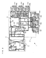
- FIG. 2 is a refrigerant circuit diagram that illustrates the streams of the first-side refrigerant and second-side refrigerant in cooling only operation mode in the air-conditioning apparatus 1 illustrated in FIG. 1 .
- the pipes indicated by the thick lines represent the pipes through which the first-side refrigerant and second-side refrigerant pass, the directions in which the first-side refrigerant flows are indicated by the solid line arrows, and the directions in which the second-side refrigerant flows are indicated by the broken line arrows.
- FIGS. 3 to 7 The cooling only operation mode is described below with reference to FIG. 2 .
- the first flow switching device 106 is switched in advance such that the first-side refrigerant discharged from the compressor 103 flows into the heat-source-side heat exchanger 104 and the first-side refrigerant exiting from the intermediate unit 1B flows into the compressor 103.
- the valves 111a, 111b, and 111f are in a closed state, and the valves 111c, 111d, and 111e are in an opened state.
- the valves 112na to 112nd, 114a, 114b, and 115ma to 115dm are in an open state, and the valves 114c and 114d are in a closed state.
- the first-side refrigerant in a low-temperature and low-pressure gaseous state is compressed by the compressor 103 to a high-temperature and high-pressure state.
- the first-side refrigerant is discharged from the compressor 103, passes through the first flow switching device 106, flows into the heat-source-side heat exchanger 104, and transfers heat to the outdoor air.
- the first-side refrigerant is partially or entirely condensed to a gas-liquid two-phase state or liquid state.
- the first-side refrigerant in the gas-liquid two-phase state or liquid state exiting from the heat-source-side heat exchanger 104 passes through the check valve 113b, exits from the outdoor unit 1A, and flows into the intermediate unit 1B.
- the first-side refrigerant flowing to the intermediate unit 1B passes through the valve 111e and is divided into portions, and the portions flow into the expansion mechanisms 105a and 105b, respectively, are thus expanded and decompressed, become a low-temperature and low-pressure gas-liquid two-phase state, and flow into the intermediate heat exchangers 107a and 107b, respectively, in parallel with each other.
- the first-side refrigerant in the gas-liquid two-phase state flowing to each of the intermediate heat exchangers 107a and 107b receives heat from the second-side refrigerant, evaporates, and becomes a low-temperature and low-pressure gaseous state.
- the first-side refrigerants in the low-temperature and low-pressure gaseous state exiting from the intermediate heat exchangers 107a and 107b pass through the valves 111c and 111d and then marge together.
- the merged first-side refrigerant exits from the intermediate unit 1B and flows into the outdoor unit 1A.
- the first-side refrigerant in the gaseous state flowing to the outdoor unit 1A passes through the check valve 113a and first flow switching device 106, is sucked into the compressor 103, and is compressed again.
- the low-temperature second-side refrigerant is caused to exit from the intermediate heat exchanger 107a by driving of the pump 109a, passes through the valves 112na, and then flows into the convective indoor heat exchangers 108n in the convective indoor units C1n.
- the low-temperature second-side refrigerant is caused to exit from the intermediate heat exchanger 107b by driving of the pump 109b, passes through the valves 112nb, and then flows into the convective indoor heat exchangers 108n in the convective indoor units C1n.
- the second-side refrigerant flowing from the intermediate unit 1B to each of the convective indoor heat exchangers 108n in the above-described way cools the indoor air, becomes a high-temperature state, exits from the convective indoor units C1n, and flows into the intermediate unit 1B.
- the second-side refrigerant exiting from each of the convective indoor heat exchangers 108n is divided into a portion that is to return to the intermediate heat exchangers 107a and 107b and another portion that is to flow into the radiant indoor units.
- the second-side refrigerant is divided into a second-side refrigerant portion that is to flow into the intermediate heat exchanger 107a through the valves 112nc and 114a and another second-side refrigerant portion that moves from the valves 112nc toward the radiant indoor units C2m.
- the second-side refrigerant is divided into a second-side refrigerant portion that is to flow into the intermediate heat exchanger 107b through the valves 112nd and 114b and another second-side refrigerant portion that moves from the valves 112nd toward the radiant indoor units C2m.
- the second-side refrigerant flowing toward the radiant indoor units C2m passes through the valves 115ma, then exits from the intermediate unit 1B, and flows into the radiant indoor heat exchangers 116m in the radiant indoor units C2m.
- the second-side refrigerant flowing from the convective indoor units C1n and flowing to the convective indoor heat exchangers 108n through the intermediate unit 1B in this way cools the indoor air, becomes a high-temperature state, exits from the convective indoor units C1n, and flows into the intermediate unit 1B.
- the second-side refrigerant exiting from the radiant indoor heat exchangers 116m flows into the intermediate unit 1B.
- the second-side refrigerant flows into the intermediate heat exchanger 107a through the valves 115mc and into the intermediate heat exchanger 107b through the valves 115dm.
- the flows of the second-side refrigerant flowing to the intermediate heat exchangers 107a and 107b are cooled by the first-side refrigerant in the low-temperature state and exit from the intermediate heat exchangers 107a and 107b, respectively.
- the flows of the second-side refrigerant exiting from the intermediate heat exchangers 107a and 107b flow into the pumps 109a and 109b, respectively, and are ejected again.
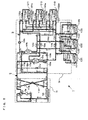
- FIG. 3 is a refrigerant circuit diagram that illustrates the streams of the first-side refrigerant and second-side refrigerant in heating only operation mode in the air-conditioning apparatus 1 illustrated in FIG. 1 .
- the heating only operation mode is described below with reference to FIG. 3 .
- the first flow switching device 106 is switched in advance such that the first-side refrigerant discharged from the compressor 103 flows into the intermediate unit 1B and the first-side refrigerant exiting from the heat-source-side heat exchanger 104 flows into the compressor 103.
- valves 111a, 111b, and 111f are in an open state, and the valves 111c, 111d, and 111e are in a closed state.
- the valves 112na to 112nd, 114a, 114b, and 115ma to 115dm are in an open state, and the valves 114c and 114d are in a closed state, as in the case of the cooling only operation mode.
- the first-side refrigerant in a low-temperature and low-pressure gaseous state is compressed by the compressor 103 to a high-temperature and high-pressure state.
- the first-side refrigerant is discharged from the compressor 103, passes through the first flow switching device 106 and check valve 113c, exits from the outdoor unit 1A, and flows into the intermediate unit 1B.
- the first-side refrigerant flowing to the intermediate unit 1B is divided into portions that are to flow into the intermediate heat exchangers 107a and 107b in parallel with each other through the valves 111a and 111b, respectively.
- the first-side refrigerants in the high-temperature and high-pressure state flowing to the intermediate heat exchangers 107a and 107b transfer heat to the second-side refrigerant and are partially or entirely condensed to a gas-liquid two-phase state or liquid state.
- the first-side refrigerant in the gas-liquid two-phase state flowing to the outdoor unit 1A passes through the check valve 113d, flows into the heat-source-side heat exchanger 104, receives heat from the outdoor air, evaporates, becomes a low-temperature and low-pressure gaseous state, passes through the first flow switching device 106, is sucked into the compressor 103, and is compressed again.
- the flow of the second-side refrigerant in the second-side refrigerant circuit is substantially the same as those in the cooling only operation mode, and only heat movements different from those in the cooling only operation mode are described below.
- the high-temperature flows of the second-side refrigerant from the pumps 109a and 109b heat the indoor air in the convective heat exchangers 108n, become a low-temperature state, heat the indoor air in the radiant indoor heat exchangers 116m, become a further lower temperature state, and are then heated in the intermediate heat exchangers 107a and 107b by the first-side refrigerant in the high-temperature state.
- the flows of the second-side refrigerant in the high-temperature state flow into the pumps 109a and 109b and are ejected again.
- FIG. 4 is a refrigerant circuit diagram that illustrates the streams of the first-side refrigerant and the second-side refrigerant in cooling main operation mode 1 in the air-conditioning apparatus 1 illustrated in FIG. 1 .
- the cooling main operation mode 1 is the operation mode in which the cooling load is larger than the heating load and at least one of the convective indoor units C1n performs heating operation.
- the convective indoor unit C11 and radiant indoor unit C21 perform heating operation
- the convective indoor units C12 and C13 and radiant indoor units C22 and C23 perform cooling operation.
- the first flow switching device 106 is switched in advance such that the first-side refrigerant discharged from the compressor 103 flows into the heat-source-side heat exchanger 104 and the first-side refrigerant exiting from the intermediate unit 1B flows into the compressor 103.
- the valves 111a, 111d, 111e, and 111f are in a closed state, and the valves 111b and 111c are in an open state.
- valves 1121b, 1121d, 1122a, 1122c, 1123a, 1123c, 114a, 114b, 1151b, 1151d, 1152a, 1152c, 1153a, and 1153c are in an open state, and the valves 1121a, 1121c, 1122b, 1122d, 1123b, 1123d, 114c, 114d, 1151a, 1151c, 1152b, 1152d, 1153b, and 1153d are in a closed state.
- the first-side refrigerant in a low-temperature and low-pressure gaseous state is compressed by the compressor 103, becomes a high-temperature and high-pressure state, is discharged, passes through the first flow switching device 106, flows into the heat-source-side heat exchanger 104, transfers heat to the outdoor air, and is partially or entirely condensed to a gas-liquid two-phase state.
- the first-side refrigerant in the gas-liquid two-phase state exiting from the heat-source-side heat exchanger 104 passes through the check valve 113b, exits from the outdoor unit 1A, and flows into the intermediate unit 1B.
- the first-side refrigerant in the gas-liquid two-phase state flowing to the intermediate unit 1B passes through the valve 111b, flows into the intermediate heat exchanger 107b, heats the second-side refrigerant, and is thus further condensed.
- the first-side refrigerant exiting from the intermediate heat exchanger 107b passes through the expansion mechanisms 105b and 105a, is thus expanded and decompressed, becomes a low-temperature and low-pressure gas-liquid two-phase state, and flows into the intermediate heat exchanger 107a.
- the first-side refrigerant in the gas-liquid two-phase state flowing to the intermediate heat exchanger 107a receives heat from the second-side refrigerant, evaporates, and becomes a low-temperature and low-pressure gaseous state.
- the first-side refrigerant in the low-temperature and low-pressure gaseous state exiting from the intermediate heat exchanger 107a passes through the valve 111c, exits from the intermediate unit 1B, and flows into the outdoor unit 1A.
- the first-side refrigerant in the gaseous state flowing to the outdoor unit 1A passes through the check valve 113a and first flow switching device 106, is sucked into the compressor 103, and is compressed again.
- the low-temperature second-side refrigerant ejected by driving of the pump 109a is divided into portions, and the portions pass through the valves 1122a and 1123a, respectively, exit from the intermediate unit 1B, and flow into the convective indoor heat exchanger 1082 in the convective indoor unit C12 and the convective indoor heat exchanger 1083 in the convective indoor unit C13, respectively.
- the flows of the second-side refrigerant flowing to the convective indoor heat exchangers 1082 and 1083 cool the indoor air, become a high-temperature state, exit from the convective indoor units C12 and C13, respectively, and flow into the intermediate unit 1B.
- the second-side refrigerant exiting from the convective indoor heat exchanger 1082, flowing to the intermediate unit 1B, and passing through the valve 1122c and the second-side refrigerant exiting from the convective indoor heat exchanger 1083, flowing to the intermediate unit 1B, and passing through the valve 1123c merge with each other, and the merged second-side refrigerant is then divided into a portion that is to pass through the valve 114a and another portion that is to move toward the indoor units C22 and C23.
- the second-side refrigerant flowing toward the indoor units C22 and C23 is divided again into portions, and the portions pass through the valves 1152a and 1153a, respectively, exit from the intermediate unit 1B, and flow into the radiant indoor heat exchanger 1162 in the indoor unit C22 and the radiant indoor heat exchanger 1163 in the indoor unit C23, respectively.
- the flows of the second-side refrigerant flowing to the radiant indoor heat exchangers 1162 and 1163 cool the indoor air, become a higher temperature state, exit from the indoor units C22 and C23, respectively, and flow into the intermediate unit 1B again.
- the second-side refrigerant exiting from the radiant indoor heat exchanger 1162, flowing to the intermediate unit 1B, and passing through the valve 1152c and the second-side refrigerant exiting from the radiant indoor heat exchanger 1163, flowing to the intermediate unit 1B, and passing through the valve 1153c merge with the second-side refrigerant passing through the valve 114a, and the merged second-side refrigerant flows into the intermediate heat exchanger 107a.
- the second-side refrigerant flowing to the intermediate heat exchanger 107a is cooled by the first-side refrigerant in the low-temperature state and exits from the intermediate heat exchanger 107a.
- the second-side refrigerant exiting from the intermediate heat exchanger 107a flows into the pump 109a and is ejected again.
- the high-temperature second-side refrigerant ejected by driving of the pump 109b passes through the valve 1121b, exits from the intermediate unit 1B, and flows into the convective indoor heat exchanger 1081 in the convective indoor unit C11.
- the second-side refrigerant flowing to the convective indoor heat exchanger 1081 heats the indoor air, becomes a low-temperature state, exits from the convective indoor unit C11, and flows into the intermediate unit 1B.
- the second-side refrigerant exiting from the convective indoor heat exchanger 1081, flowing to the intermediate unit 1B, and passing through the valve 1121d is divided into a portion that is to pass through the valve 114b and another portion that is to move toward the indoor unit C21.
- the second-side refrigerant flowing toward the indoor unit C21 passes through the valve 1151b, exits from the intermediate unit 1B, and flows into the radiant indoor heat exchanger 1161 in the indoor unit C21.
- the second-side refrigerant flowing to the radiant indoor heat exchanger 1161 cools the indoor air, becomes a higher temperature state, exits from the indoor unit C21, and flows into the intermediate unit 1B again.
- the second-side refrigerant exiting from the radiant indoor heat exchanger 1161, flowing to the intermediate unit 1B, and passing through the valve 1151d merges with the second-side refrigerant passing through the valve 114b, and the merged second-side refrigerant flows into the intermediate heat exchanger 107b.
- the second-side refrigerant flowing to the intermediate heat exchanger 107b is heated by the first-side refrigerant in the high-temperature state and exits from the intermediate heat exchanger 107b.
- the second-side refrigerant exiting from the intermediate heat exchanger 107b flows into the pump 109b and is ejected again.
- FIG. 5 is a refrigerant circuit diagram that illustrates the streams of the first-side refrigerant and the second-side refrigerant in cooling main operation mode 2 in the air-conditioning apparatus 1 illustrated in FIG. 1 .
- the cooling main operation mode 2 is the operation mode in which the cooling load is larger than the heating load, all of the convective indoor units C11 to C13 perform cooling operation, and at least one of the indoor units C21 to C23 performs heating operation.
- the cooling main operation mode 2 is described below with reference to FIG. 5 .
- the convective indoor units C11 to C13 and radiant indoor units C22 and C23 perform cooling operation
- the radiant indoor unit C21 performs heating operation.
- the passage switching in the first-side refrigerant circuit 2 is substantially the same as in the cooling main operation mode 1.
- the flow of the second-side refrigerant in the second-side refrigerant circuit is described below.
- valves 1121a to 1123a, 1121c to 1123c, 114a, 114b, 114d, 1151b, 1151d, 1152a, 1152c, 1153a, and 1153c are in an open state, and the valves 1121b to 1123b, 1121d to 1123d, 114c, 1151a, 1151c, 1152b, 1152d, 1153b, and 1153d are in a closed state.
- the low-temperature second-side refrigerant ejected by driving of the pump 109a is divided into portions, and the portions pass through the valves 1121a, 1122a, and 1123a, respectively, exit from the intermediate unit 1B, and flow into the convective indoor heat exchanger 1081 in the convective indoor unit C11, the convective indoor heat exchanger 1082 in the convective indoor unit C12, and the convective indoor heat exchanger 1083 in the convective indoor unit C13, respectively.
- the flows of the second-side refrigerant flowing to the convective indoor heat exchangers 1081, 1082, and 1083 cool the indoor air, become a high-temperature state, exit from the convective indoor units C11, C12, and C13, respectively, and flow into the intermediate unit 1B.
- the second-side refrigerant passing through the valve 1121c and flowing to the intermediate unit 1B, the second-side refrigerant passing through the valve 1122c and flowing to the intermediate unit 1B, and the second-side refrigerant passing through the valve 1123c and flowing to the intermediate unit 1B are divided into a portion that is to pass through the valve 114a and another portion that is to move toward the indoor units C22 and C23.
- the second-side refrigerant flowing toward the indoor units C22 and C23 is further divided into portions, and the portions pass through the valves 1152a and 1153a, respectively, exit from the intermediate unit 1B, and flow into the radiant indoor heat exchanger 1162 in the indoor unit C22 and the radiant indoor heat exchanger 1163 in the indoor unit C23, respectively.
- the flows of the second-side refrigerant flowing to the radiant indoor heat exchangers 1162 and 1163 cool the indoor air, become a higher temperature state, exit from the indoor units C22 and C23, respectively, and flows into the intermediate unit 1B again.
- the second-side refrigerant exiting from the radiant indoor heat exchanger 1162, flowing to the intermediate unit 1B, and passing through the valve 1152c and the second-side refrigerant exiting from the radiant indoor heat exchanger 1163, flowing to the intermediate unit 1B, and passing through the valve 1153c merge with the second-side refrigerant passing through the valve 114a, and the merged second-side refrigerant flows into the intermediate heat exchanger 107a.
- the second-side refrigerant flowing to the intermediate heat exchanger 107a is cooled by the first-side refrigerant in the low-temperature state and exits from the intermediate heat exchanger 107a.
- the second-side refrigerant exiting from the intermediate heat exchanger 107a flows into the pump 109a and is ejected again.
- the high-temperature second-side refrigerant ejected by driving of the pump 109b passes through the valve 114d and is then divided into a portion that is to pass through the valve 114b and another portion that is to move toward the indoor unit C21.
- the second-side refrigerant flowing toward the indoor unit C21 passes through the valve 1151b, exits from the intermediate unit 1B, and flows into the radiant indoor heat exchanger 1161 in the indoor unit C21.
- the second-side refrigerant flowing to the radiant indoor heat exchanger 1161 heats the indoor air, becomes a low-temperature state, exits from the indoor unit C21, and flows into the intermediate unit 1B.
- the second-side refrigerant exiting from the radiant indoor heat exchanger 1161, flowing to the intermediate unit 1B, and passing through the valve 1151d merges with the second-side refrigerant passing through the valve 114b, and the merged second-side refrigerant flows into the intermediate heat exchanger 107b.
- the second-side refrigerant flowing to the intermediate heat exchanger 107b is heated by the first-side refrigerant in the high-temperature state and exits from the intermediate heat exchanger 107b.
- the second-side refrigerant exiting from the intermediate heat exchanger 107b flows into the pump 109b and is ejected again.
- FIG. 6 is a refrigerant circuit diagram that illustrates the streams of the first-side refrigerant and the second-side refrigerant in heating main operation mode 1 in the air-conditioning apparatus 1 illustrated in FIG. 1 .
- the heating main operation mode 1 is the operation mode in which the heating load is larger than the cooling load and at least one of the convective indoor units C11 to C13 performs cooling operation.
- the heating main operation mode 1 is described below with reference to FIG. 6 .
- the convective indoor units C11 and C12 and radiant indoor units C21 and C22 perform heating operation
- the convective indoor unit C13 and radiant indoor unit C23 perform cooling operation.
- the first flow switching device 106 is switched in advance such that the first-side refrigerant discharged from the compressor 103 flows into the intermediate unit 1B and the first-side refrigerant exiting from the heat-source-side heat exchanger 104 flows into the compressor 103.
- the valves 111b and 111c are in an open state, and the valves 111a and 111d to 111f are in a closed state.
- valves 1121b, 1121d, 1122b, 1122d, 1123a, 1123c, 114a, 114b, 1151b, 1151d, 1152b, 1152d, 1153a, and 1153c are in an open state.
- the valves 1121a, 1121c, 1122a, 1122c, 1123b, 1123d, 114c, 114d, 1151a, 1151c, 1152a, 1152c, 1153b, and 1153d are in a closed state.
- the first-side refrigerant in the low-temperature and low-pressure gaseous state is compressed by the compressor 103, becomes a high-temperature and high-pressure state, is discharged, passes through the first flow switching device 106 and check valve 113c, exits from the outdoor unit 1A, and flows into the intermediate unit 1B.
- the first-side refrigerant in the high-temperature and high-pressure state flowing to the intermediate unit 1B passes through the valve 111b, flows into the intermediate heat exchanger 107b, transfers heat to the first-side refrigerant, and is partially or entirely condensed to a gas-liquid two-phase state or a liquid state.
- the second-side refrigerant exiting from the intermediate heat exchanger 107b is expanded and decompressed by passing through the expansion mechanisms 105b and 105a, becomes a low-temperature and low-pressure gas-liquid two-phase state, and flows into the intermediate heat exchanger 107a.
- the first-side refrigerant in the gas-liquid two-phase state flowing to the intermediate heat exchanger 107a receives heat from the second-side refrigerant, and partially evaporates.
- the first-side refrigerant exiting from the intermediate heat exchanger 107a passes through the valve 111c, exits from the intermediate unit 1B, and flows into the outdoor unit 1A.
- the first-side refrigerant flowing to the outdoor unit 1A passes through the check valve 113d, flows into the heat-source-side heat exchanger 104, receives heat from the outdoor air, evaporates, becomes a low-temperature and low-pressure gaseous state, passes through the first flow switching device 106, is sucked into the compressor 103, and is compressed again.
- the low-temperature second-side refrigerant ejected by driving of the pump 109a passes through the valve 1123a, then exits from the intermediate unit 1B, and flows into the convective indoor heat exchanger 1083 in the convective indoor unit C13.
- the second-side refrigerant flowing to the convective indoor heat exchanger 1083 cools the indoor air, becomes a high-temperature state, exits from the convective indoor unit C13, and flows into the intermediate unit 1B.
- the second-side refrigerant exiting from the convective indoor heat exchanger 1083, flowing to the intermediate unit 1B, and passing through the valve 1123c is divided into a portion that is to pass through the valve 114a and another portion that is to move toward the indoor unit C23.
- the second-side refrigerant flowing toward the indoor unit C23 passes through the valve 1153a, exits from the intermediate unit 1B, and flows into the radiant indoor heat exchanger 1163 in the indoor unit C23.
- the second-side refrigerant flowing to the radiant indoor heat exchanger 1163 cools the indoor air, becomes a higher temperature state, exits from the indoor unit C23, and flows into the intermediate unit 1B again.
- the second-side refrigerant exiting from the radiant indoor heat exchanger 1163, flowing to the intermediate unit 1B, and passing through the valve 1153c merges with the second-side refrigerant passing through the valve 114a, and the merged second-side refrigerant flows into the intermediate heat exchanger 107a.
- the second-side refrigerant flowing to the intermediate heat exchanger 107a is cooled by the first-side refrigerant in the low-temperature state and exits from the intermediate heat exchanger 107a.
- the second-side refrigerant exiting from the intermediate heat exchanger 107a flows into the pump 109a and is ejected again.
- the high-temperature second-side refrigerant ejected by driving of the pump 109b is divided into portions, and the portions pass through the valves 1121b and 1122b, respectively, exit from the intermediate unit 1B, and flow into the convective indoor heat exchanger 1081 in the convective indoor unit C11 and the convective indoor heat exchanger 1082 in the convective indoor unit C12, respectively.
- the flows of the second-side refrigerant flowing to the convective indoor heat exchangers 1081 and 1082 heat the indoor air, become a low-temperature state, exit from the convective indoor units C11 and C12, respectively, and flow into the intermediate unit 1B.
- the second-side refrigerant exiting from the convective indoor heat exchanger 1081, flowing to the intermediate unit 1B, and passing through the valve 1121d and the second-side refrigerant exiting from the convective indoor heat exchanger 1082, flowing to the intermediate unit 1B, and passing through the valve 1122d merge with each other, and the merged second-side refrigerant is divided into a portion that is to pass through the valve 114b and another portion that is to move toward the indoor units C21 and C22.
- the second-side refrigerant flowing toward the indoor units C21 and C22 is divided again into portions, and the portions pass through the valves 1151b and 1152b, respectively, exit from the intermediate unit 1B, and flow into the radiant indoor heat exchanger 1161 in the indoor unit C21 and the radiant indoor heat exchanger 1162 in the indoor unit C22, respectively.
- the flows of the second-side refrigerant flowing to the radiant indoor heat exchangers 1161 and 1162 heat the indoor air, become a lower temperature state, exit from the indoor units C21 and C22, respectively, and flow into the intermediate unit 1B again.
- the second-side refrigerant exiting from the radiant indoor heat exchanger 1161, flowing to the intermediate unit 1B, and passing through the valve 1151d and the second-side refrigerant exiting from the radiant indoor heat exchanger 1162, flowing to the intermediate unit 1B, and passing through the valve 1152d merge with the second-side refrigerant passing through the valve 114b, and the merged second-side refrigerant flows into the intermediate heat exchanger 107b.
- the second-side refrigerant flowing to the intermediate heat exchanger 107b is heated by the first-side refrigerant in the high-temperature state and exits from the intermediate heat exchanger 107b.
- the second-side refrigerant exiting from the intermediate heat exchanger 107b flows into the pump 109b and is ejected again.
- FIG. 7 is a refrigerant circuit diagram that illustrates the streams of the first-side refrigerant and the second-side refrigerant in heating main operation mode 2 in the air-conditioning apparatus 1 illustrated in FIG. 1 .
- the heating main operation mode 2 is the operation mode in which the heating load is larger than the cooling load, all of the convective indoor units C11 to C13 perform heating operation, and at least one of the indoor units C21 to C23 perform cooling operation.
- the heating main operation mode 2 is described below with reference to FIG. 7 .
- the convective indoor units C11 to C13 and radiant indoor units C21 and C22 perform heating operation
- the radiant indoor unit C23 performs cooling operation.
- the first flow switching device 106 is switched in advance such that the first-side refrigerant discharged from the compressor 103 flows into the heat-source-side heat exchanger 104 and the first-side refrigerant exiting from the intermediate unit 1B flows into the compressor 103.
- the valves 111a, 111d, 111e, and 111f are in a closed state, and the valves 111b and 111c are in an opened state.
- valves 1121b to 1123b, 1121d to 1123d, 114a, 114b, 114c, 1151b, 1151d, 1152b, 1152d, 1153a, and 1153c are in an open state, and the valves 1121a to 1123a, 1121c to 1123c, 114d, 1151a, 1151c, 1152a, 1152c, 1153b, and 1153d are in a closed state.
- the refrigerant flow in the first-side refrigerant circuit 2 is substantially the same as in the heating main operation mode 1, and the description thereof is omitted.
- the flow of the second-side refrigerant in the second-side refrigerant circuit is only described.
- the low-temperature second-side refrigerant ejected by driving of the pump 109a passes through the valve 114c and is divided into a portion that is to pass through the valve 114a and another portion that is to move toward the indoor unit C23.
- the second-side refrigerant flowing toward the indoor unit C23 passes through the valve 1153a, exits from the intermediate unit 1B, and flows into the radiant indoor heat exchanger 1163 in the indoor unit C23.
- the second-side refrigerant flowing to the radiant indoor heat exchanger 1163 cools the indoor air, becomes a high-temperature state, exits from the indoor unit C23, and flows into the intermediate unit 1B.
- the second-side refrigerant flowing to the intermediate heat exchanger 107a is cooled by the first-side refrigerant in the low-temperature state and exits from the intermediate heat exchanger 107a.
- the second-side refrigerant exiting from the intermediate heat exchanger 107a flows into the pump 109a and is ejected again.
- the high-temperature second-side refrigerant ejected by driving of the pump 109b is divided into portions, and the portions pass through the valves 1121b, 1122b, and 1123b, respectively, exit from the intermediate unit 1B, and flow into the convective indoor heat exchanger 1081 in the convective indoor unit C11, the convective indoor heat exchanger 1082 in the convective indoor unit C12, and the convective indoor heat exchanger 1083 in the convective indoor unit C13, respectively.
- the flows of the second-side refrigerant flowing to the convective indoor heat exchangers 1081, 1082, and 1083 heat the indoor air, become a low-temperature state, exit from the convective indoor units C11, C12, and C13, respectively, and flow into the intermediate unit 1B.
- the following flow of the second-side refrigerant merge together: the second-side refrigerant exiting from the convective indoor heat exchanger 1081, flowing to the intermediate unit 1B, and passing through the valve 1121d; the second-side refrigerant exiting from the convective indoor heat exchanger 1082, flowing to the intermediate unit 1B, and passing through the valve 1122d; and the second-side refrigerant exiting from the convective indoor heat exchanger 1083, flowing to the intermediate unit 1B, and passing through the valve 1123d.
- the merged second-side refrigerant is divided into a portion that is to pass through the valve 114b and another portion that is to move toward the indoor units C21 and C22.
- the second-side refrigerant flowing toward the indoor units C21 and C22 is divided again into portions, and the portions pass through the valves 1151b and 1152b, exit from the intermediate unit 1B, and flow into the radiant indoor heat exchanger 1161 in the indoor unit C21 and the radiant indoor heat exchanger 1162 in the indoor unit C22, respectively.
- the flows of the second-side refrigerant flowing to the radiant indoor heat exchangers 1161 and 1162 heat the indoor air, become a lower temperature state, exit from the indoor units C21 and C22, respectively, and flow into the intermediate unit 1B again.
- the second-side refrigerant exiting from the radiant indoor heat exchanger 1161, flowing to the intermediate unit 1B, and passing through the valve 1151d and the second-side refrigerant exiting from the radiant indoor heat exchanger 1162, flowing to the intermediate unit 1B, and passing through the valve 1152d merge with the second-side refrigerant passing through the valve 114b, and the merged second-side refrigerant flows into the intermediate heat exchanger 107b.
- the second-side refrigerant flowing to the intermediate heat exchanger 107b is heated by the first-side refrigerant in the high-temperature state and exits from the intermediate heat exchanger 107b.
- the second-side refrigerant exiting from the intermediate heat exchanger 107b flows into the pump 109b and is ejected again.
- the number of the convective indoor units C1n including the convective indoor heat exchangers 108n and the number of the radiant indoor units C2m including the radiant indoor heat exchangers 116m may be any number, and cooling and heating in each of the indoor units C may be freely set.
- air-conditioning that can rise fast and that can withstand large heating and cooling loads can be performed in rooms equipped with the convective indoor units C1n, and uniform air-conditioning can be performed in rooms equipped with the radiant indoor units C2m without causing noise or draft. Accordingly, high-quality air-conditioning can be performed in all of the rooms as the entire structure in accordance with the use and load of each of the rooms.
- the use of a single air-conditioning system including the convective indoor units C1n including the convective heat exchangers 108n and the radiant indoor units C2m including the radiant indoor heat exchangers 116m can achieve space and energy savings larger than those in a case where both a convective air-conditioning system and a radiant air-conditioning system are installed.
- the radiant indoor heat exchangers 116m are disposed downflow of the convective indoor heat exchangers 108n in the second-side refrigerant circuit.
- cooling only operation mode and cooling main operation mode 1 for example, after the second-side refrigerant of 5 °C is supplied to the convective indoor heat exchangers 108n and its temperature is raised to 15 °C by heat exchange in the convective indoor heat exchangers 108n, the second-side refrigerant is supplied to the radiant indoor heat exchangers 116m.
- the second-side refrigerant supplied to the radiant indoor heat exchangers 116m after heat exchange in the convective indoor heat exchangers 108n has a temperature higher than that supplied to the convective indoor heat exchangers 108n. Accordingly, both the convective indoor heat exchangers 108n and radiant indoor heat exchangers 116m can perform appropriate air-conditioning.
- both the convective indoor heat exchangers 108n and the radiant indoor heat exchangers 116m can perform appropriate air-conditioning.
- the second-side refrigerant supplied to the radiant indoor heat exchangers 116m after heat exchange in the convective indoor heat exchangers 108n has a temperature lower than that supplied to the convective indoor heat exchangers 108n.
- the second-side refrigerant of 45 °C is supplied to the convective indoor heat exchangers 108n, its temperature is reduced to 130 °C by heat exchange in the convective indoor heat exchangers 108n, and then the second-side refrigerant is supplied to the radiant indoor heat exchangers 116m. Accordingly, both the convective indoor heat exchangers 108n and the radiant indoor heat exchangers 116m can perform appropriate air-conditioning.
- the valve 114b is in an open state and the convective indoor heat exchangers 108n do not perform heating, the temperature of the second-side refrigerant produced in the intermediate heat exchanger 107b can be slightly decreased, an input of the compressor can be reduced, and the operation efficiency is enhanced.
- heating main operation mode 2 because the valve 114a is in an open state and the convective indoor heat exchangers 108n do not perform cooling, the temperature of the second-side refrigerant produced in the intermediate heat exchanger 107a can be slightly increased, an input of the compressor can be reduced, and the operation efficiency can be enhanced.
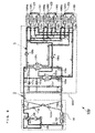
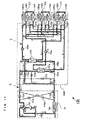
- FIGS. 8 to 11 are refrigerant circuit diagrams that illustrate Embodiment 2 of the air-conditioning apparatus of the present invention.
- An air-conditioning apparatus 100 is described with reference to FIG. 8 .
- the same reference numerals are used in the components having the same configurations in the air-conditioning apparatus 100 in FIG. 8 as in the air-conditioning apparatus 1 in FIG. 1 , and the description thereof is omitted.
- the air-conditioning apparatus 100 in FIG. 8 differs from the air-conditioning apparatus 1 in FIG. 1 in the configurations of the intermediate unit and indoor units.
- the second-side refrigerant circuit in the intermediate unit 100B includes at least the intermediate heat exchangers 107a and 107b, convective indoor heat exchangers 108n, radiant indoor heat exchangers 116n, pumps 109a and 109b, and valves 112na to 112nd.
- the second-side refrigerant circuit is configured as the refrigerant circuit by connecting mainly the pumps 109a and 109b, convective indoor heat exchangers 108n, radiant indoor heat exchangers 116n, intermediate heat exchangers 107a and 107b, and pumps 109a and 109b in this order by the refrigerant pipes.
- the intermediate unit 100B is disposed on a location or the like different from the outdoor space and indoor space as a housing different from the outdoor unit 1A and indoor units C and connects the outdoor unit 1A and indoor units C3n through the refrigerant pipes.
- the intermediate unit 1B includes the intermediate heat exchangers 107a and 107b, expansion mechanisms 105a and 105b, pumps 109a and 109b, and valves 111a to 111f and 112na to 112nd.
- the intermediate heat exchanger 107a is disposed between the refrigerant pipe with which the valve 112nc merges and the pump 109a
- the intermediate heat exchanger 107b is disposed between the refrigerant pipe with which the valve 112nd merges and the pump 109b.
- Each of the convective and radiant indoor units C3n performs air-conditioning by cooling operation or heating operation on an indoor space and includes the convective heat exchanger 108n, blower device 108na, and radiant indoor heat exchanger 116n.
- the valves 112na and 112nb in the intermediate unit 100B are connected to the inlet side of the convective heat exchanger 108n in the indoor unit C3n.
- the discharge side of the convective heat exchanger 108n is connected to the inlet side of the radiant indoor heat exchanger 116n.
- the radiant indoor heat exchanger 116n is disposed downflow of the convective heat exchanger 108n and connected in series.
- the discharge side of the radiant indoor heat exchanger 116n is connected to the valves 112nc and 112nd in the intermediate unit 100B.
- the indoor air or outside air supplied from the blower device 108na exchanges heat with the second-side refrigerant in the indoor heat exchanger 108n, and then it exchanges heat again with the second-side refrigerant in the radiant indoor heat exchanger 116n.
- the number n of the convective and radiant indoor units C3n connected is three.
- the number n is not limited to three, and any number of the convective and radiant indoor units C3n may be used.
- FIGS. 9 to 14 are refrigerant circuit diagrams that illustrate example streams of the first-side refrigerant and the second-side refrigerant in operation modes. Example operations in the air-conditioning apparatus 100 in each operation mode are described with reference to FIGS. 9 to 14 .
- the flow of the first-side refrigerant is substantially the same as in Embodiment 1 described above (see FIGS. 2 to 7 ), and the flow of the second-side refrigerant is only described below.
- FIG. 9 is a refrigerant circuit diagram that illustrates the streams of the first-side refrigerant and second-side refrigerant in cooling only operation mode in the air-conditioning apparatus 100 illustrated in FIG. 8 .
- the pipes indicated by the thick lines represent the pipes through which the first-side refrigerant and second-side refrigerant pass, the directions in which the first-side refrigerant flows are indicated by the solid line arrows, and the directions in which the second-side refrigerant flows are indicated by the broken line arrows.
- FIGS. 10 to 12 The cooling only operation mode is described below with reference to FIG. 9 .
- the valves 112na to 112nd are set in an open state in advance.
- the low-temperature second-side refrigerant ejected by driving of the pump 109a is divided into portions, and the portions pass through the valves 1121a, 1122a, and 1123a, respectively, then exit from the intermediate unit 1B, and flow into the convective indoor heat exchanger 1081 in the convective and radiant indoor unit C31, the convective indoor heat exchanger 1082 in the convective and radiant indoor unit C32, and the convective indoor heat exchanger 1083 in the convective and radiant indoor unit C33, respectively.
- the low-temperature second-side refrigerant ejected by driving of the pump 109b is divided into portions, and the portions pass through the valves 1121b, 1122b, and 1123b, respectively, then exit from the intermediate unit 1B, and flow into the convective indoor heat exchanger 1081 in the convective and radiant indoor unit C31, the convective indoor heat exchanger 1082 in the convective and radiant indoor unit C2, and the convective indoor heat exchanger 1083 in the convective and radiant indoor unit C33, respectively.
- the flows of the second-side refrigerant flowing to the convective indoor heat exchangers 1081, 1082, and 1083 cool the indoor air or outside air, become a high-temperature state, and flow into the radiant indoor heat exchangers 1161, 1162, respectively.
- the flows of the second-side refrigerant flowing to the radiant indoor heat exchangers 1161, 1162, and 1163 cool the air subjected to heat treatment in the convective indoor heat exchangers 1081, 1082, and 1083, respectively, and indoor air, become a higher temperature state, exit from the convective and radiant indoor units C31, C32, and C33, respectively, and flow into the intermediate unit 1B.
- the flows of the second-side refrigerant flowing to the intermediate heat exchangers 107a and 107b are cooled by the first-side refrigerant in the low-temperature state and exit from the intermediate heat exchangers 107a and 107b, respectively.
- the flows of the second-side refrigerant exiting from the intermediate heat exchangers 107a and 107b flow into the pumps 109a and 109b, respectively, and are ejected again.
- FIG. 10 is a refrigerant circuit diagram that illustrates the streams of the first-side refrigerant and second-side refrigerant in heating only operation mode in the air-conditioning apparatus 100 illustrated in FIG. 8 .
- the heating only operation mode is described below with reference to FIG. 10 .
- the flow of the second-side refrigerant in the second-side refrigerant circuit is described here.
- the flow of the second-side refrigerant is substantially the same as in cooling only operation mode.
- the valves 112na to 112nd are set in an open state in advance.
- the high-temperature second-side refrigerant ejected by driving of the pump 109a is divided into portions, and the portions pass through the valves 112na, 1122a, and 1123a, respectively, then exit from the intermediate unit 1B, and flow into the convective indoor heat exchanger 1081 in the convective and radiant indoor unit C31, the convective indoor heat exchanger 1082 in the convective and radiant indoor unit C32, and the convective indoor heat exchanger 1083 in the convective and radiant indoor unit C33, respectively.
- the high-temperature second-side refrigerant ejected by driving of the pump 109b is divided into portions, and the portions pass through the valves 1121b, 1122b, and 1123b, respectively, then exit from the intermediate unit 1B, and flow into the convective indoor heat exchanger 1081 in the convective indoor unit C1, the convective indoor heat exchanger 1082 in the convective and radiant indoor unit C32, and the convective indoor heat exchanger 1083 in the convective and radiant indoor unit C33, respectively.
- the flows of the second-side refrigerant flowing to the convective indoor heat exchangers 1081, 1082, and 1083 heat the indoor air or outside air, become a low-temperature state, and flow into the radiant indoor heat exchangers 1161, 1162, and 1163, respectively.
- the flows of the second-side refrigerant flowing to the radiant indoor heat exchangers 1161, 1162, and 1163 heat the air subjected to heat treatment in the convective indoor heat exchangers 1081, 1082, and 1083, respectively, and indoor air, become a lower temperature state, exit from the convective and radiant indoor units C31, C32, and C33, respectively, and flow into the intermediate unit 1B.
- the flows of the second-side refrigerant flowing to the intermediate heat exchangers 107a and 107b are heated by the first-side refrigerant in the high-temperature state and exit from the intermediate heat exchangers 107a and 107b, respectively.
- the flows of the second-side refrigerant exiting from the intermediate heat exchangers 107a and 107b flow into the pumps 109a and 109b, respectively, and are ejected again.
- FIG. 11 is a refrigerant circuit diagram that illustrates the streams of the first-side refrigerant and the second-side refrigerant in cooling main operation mode in the air-conditioning apparatus 100 illustrated in FIG. 8 .
- the cooling main operation mode is described below with reference to FIG. 11 .
- the convective and radiant indoor unit C31 performs heating operation
- the convective and radiant indoor units C32 and C33 perform cooling operation.
- valves 1121b, 1121d, 1122a, 1122c, 1123a, and 1123c are set in an open state in advance, and the valves 1121a, 1121c, 1122b, 1122d, 1123b, and 1123d are set in a closed state in advance.
- the low-temperature second-side refrigerant ejected by driving of the pump 109a is divided into portions, and the portions pass through the valves 1122a and 1123a, respectively, then exit from the intermediate unit 1B, and flow into the convective indoor heat exchanger 1082 in the convective and radiant indoor unit C32 and the convective indoor heat exchanger 1083 in the convective and radiant indoor unit C33, respectively.
- the flows of the second-side refrigerant flowing to the convective indoor heat exchangers 1082 and 1083 cool the indoor air or outside air, become a high-temperature state, and flow into the radiant indoor heat exchangers 1162 and 1163, respectively.
- the flows of the second-side refrigerant flowing to the radiant indoor heat exchangers 1162 and 1163 cool the air subjected to heat treatment in convective indoor heat exchangers 1082 and 1083, respectively, and indoor air, become a higher temperature state, exit from the convective and radiant indoor units C32 and C33, respectively, and flow into the intermediate unit 1B.
- the second-side refrigerant flowing to the intermediate heat exchanger 107a is cooled by the first-side refrigerant in the low-temperature state and exits from the intermediate heat exchanger 107a.
- the second-side refrigerant exiting from the intermediate heat exchanger 107a flows into the pump 109a and is ejected again.
- the high-temperature second-side refrigerant ejected by driving of the pump 109b passes through the valve 1121b, then exits from the intermediate unit 1B, and flows into the convective indoor heat exchanger 1081 in the convective and radiant indoor unit C31.
- the second-side refrigerant flowing to the convective indoor heat exchanger 1081 heats the indoor air, becomes a low-temperature state, and flows into the radiant indoor heat exchanger 1161.
- the second-side refrigerant flowing to the radiant indoor heat exchanger 1161 heats the air subjected to heat treatment in the convective indoor heat exchanger 1081 and indoor air, becomes a lower temperature state, exits from the convective and radiant indoor unit C31, and flows into the intermediate unit 1B.
- the second-side refrigerant flowing to the intermediate heat exchanger 107b is heated by the first-side refrigerant in the high-temperature state and exits from the intermediate heat exchanger 107b.
- the second-side refrigerant exiting from the intermediate heat exchanger 107b flows into the pump 109b and is ejected again.
- FIG. 12 is a refrigerant circuit diagram that illustrates the streams of the first-side refrigerant and the second-side refrigerant in heating main operation mode in the air-conditioning apparatus 100 illustrated in FIG. 8 .
- the heating main operation mode is described below with reference to FIG. 12 .
- the convective and radiant indoor units C31 and C32 perform heating operation
- the convective and radiant indoor unit C33 performs cooling operation.
- valves 1121b, 1121d, 1122b, 1122d, 1123a, and 1123c are set in an open state in advance, and the valves 1121a, 1121c, 1122a, 1122c, 1123b, and 1123d are set in a closed state in advance.
- the low-temperature second-side refrigerant ejected by driving of the pump 109a passes through the valve 1123a, then exits from the intermediate unit 1B, and flows into the convective indoor heat exchanger 1083 in the convective and radiant indoor unit C33.
- the second-side refrigerant flowing to the convective indoor heat exchanger 1083 cools the indoor air, becomes a high-temperature state, and flows into the radiant indoor heat exchanger 1163.
- the second-side refrigerant flowing to the radiant indoor heat exchanger 1163 heats the air subjected to heat treatment in the convective indoor heat exchanger 1083 and indoor air, becomes a higher temperature state, exits from the convective and radiant indoor unit C31, and flows into the intermediate unit 1B.
- the second-side refrigerant flowing to the intermediate heat exchanger 107a is cooled by the first-side refrigerant in the low-temperature state and exits from the intermediate heat exchanger 107a.
- the second-side refrigerant exiting from the intermediate heat exchanger 107a flows into the pump 109a and is ejected again.
- the high-temperature second-side refrigerant ejected by driving of the pump 109b is divided into portions, and the portions pass through the valves 1121b and 1122b, respectively, then exit from the intermediate unit 1B, and flow into the convective indoor heat exchanger 1081 in the convective and radiant indoor unit C31 and the convective indoor heat exchanger 1082 in the convective and radiant indoor unit C32, respectively.
- the flows of the second-side refrigerant flowing to the convective indoor heat exchangers 1081 and 1082 heat the indoor air or outside air, become a low-temperature state, and flow into the radiant indoor heat exchangers 1161 and 1162, respectively.
- the flows of the second-side refrigerant flowing to the radiant indoor heat exchangers 1161 and 1162 heat the air subjected to heat treatment in convective indoor heat exchanger 1083 and indoor air, become a lower temperature state, exit from the convective and radiant indoor units C31 and C32, respectively, and flow into the intermediate unit 1B.
- the second-side refrigerant exiting from the radiant indoor heat exchanger 1161, flowing to the intermediate unit 1B, and passing through the valve 1121d and the second-side refrigerant exiting from the radiant indoor heat exchanger 1162, flowing to the intermediate unit 1B, and passing through the valve 1122d merge with each other, and the merged second-side refrigerant flows into the intermediate heat exchanger 107b.
- the second-side refrigerant flowing to the intermediate heat exchanger 107b is heated by the first-side refrigerant in the high-temperature state and exits from the intermediate heat exchanger 107b.
- the second-side refrigerant exiting from the intermediate heat exchanger 107b flows into the pump 109b and is ejected again.
- the air-conditioning apparatus can perform air-conditioning that supports a large thermal load and that causes no or slight discomfort provided by noise or draft.
- FIGS. 13 to 15 illustrate examples of placement of the convective and radiant indoor unit C3n in the air-conditioning apparatus 100 according to Embodiment 2.
- the convective indoor heat exchanger 108 and the radiant indoor heat exchanger 116 are connected to the intermediate unit 1B by the second-side refrigerant pipe.
- the broken line arrows indicate the directions in which the second-side refrigerant flows.
- the second-side refrigerant exiting from the intermediate unit 1B runs through the convective indoor heat exchanger 108n and the radiant indoor heat exchanger 116n in this order and flows into the intermediate unit 1B.
- indoor air 1a is sucked by the blower device 108a, exchanges heat in the convective heat exchanger 108n, then exchanges heat in the radiant indoor heat exchanger 116n, and air-conditioning is thus performed.
- outside air 1b is sucked by the blower device 108a, exchanges heat in the convective heat exchanger, then exchanges heat in the radiant indoor heat exchanger 116m, and ventilation and air-conditioning are thus performed.
- the indoor air 1a and outside air 1b are sucked by the blower device 108a, exchanges heat in the convective heat exchanger, then exchanges heat in the radiant indoor heat exchanger 116, and ventilation and air-conditioning are thus performed.
- the ratio between the indoor air and the outside air may be adjusted depending on the temperature of the outside air or the quality of the indoor air. With this manner, the sensible heat cooling capacity can be improved, and the occurrence of condensation in the radiant indoor heat exchanger 116n can be prevented.
- FIG. 16 is a refrigerant circuit diagram that illustrates Embodiment 3 of the air-conditioning apparatus of the present invention.
- An air-conditioning apparatus 200 is described with reference to FIG. 16 .
- the same reference numerals are used in the components having the same configurations in the air-conditioning apparatus 200 in FIG. 16 as in the air-conditioning apparatuses 1 and 100 in FIGS. 1 and 8 , and the description thereof is omitted.
- the air-conditioning apparatus 200 in FIG. 16 differs from the air-conditioning apparatuses 1 and 100 in FIGS. 1 and 8 in that three different types of the convective indoor units C1, C2, and C3 are connected to the intermediate unit 1B.
- the air-conditioning apparatus 200 includes the convective and radiant indoor unit C31 including both the convective indoor heat exchanger 1081 and a radiant indoor heat exchanger 1164, the convective indoor units C12 and C13 including only the convective indoor heat exchangers 1081 and 1082, respectively, as a heat exchanger, and indoor units C21 to C23 including only the radiant indoor heat exchangers 116m, respectively, as a heat exchanger.
- each element and the streams of the refrigerants in operation modes are similar to those in Embodiments 1 and 2. According to Embodiment 3 described above, because the single air-conditioning apparatus 200 can install three types of indoor units, air-conditioning can be performed in accordance with the use and load of each room, while at the same time space and energy savings are achieved.
- Embodiments in the present invention are not limited to Embodiments 1 to 3 described above.
- Embodiments described above illustrate an example case where the two intermediate heat exchangers 107a and 107b are disposed inside the intermediate unit 1B. Two or more intermediate heat exchangers may also be used.
- the examples illustrated in FIGS. 13 to 15 are not limited to the illustrated ones.
- the radiant indoor heat exchangers may be of the so-called active chilled beam type or passive chilled beam type.
Landscapes
- Engineering & Computer Science (AREA)
- Mechanical Engineering (AREA)
- General Engineering & Computer Science (AREA)
- Physics & Mathematics (AREA)
- Thermal Sciences (AREA)
- Chemical & Material Sciences (AREA)
- Combustion & Propulsion (AREA)
- Compression-Type Refrigeration Machines With Reversible Cycles (AREA)
- Air Conditioning Control Device (AREA)
- Other Air-Conditioning Systems (AREA)
Abstract
Description
- The present invention relates to an air-conditioning apparatus including a plurality of indoor units and capable of heating and cooling at the same time, such as a multi-air-conditioning apparatus for a building.
- Indoor units in air-conditioning apparatuses placed in buildings, houses, or the like can use a convective (air-sending type) heat exchanger for forcibly exchanging heat using an blower device and a radiant (panel) heat exchanger for exchanging heat by natural convection without sending air using an blower device.
- The convective heat exchanger can perform quick cooling, but may cause a person to feel uncomfortable or the like by directly sending air. The radiant indoor heat exchanger can perform heating and cooling operation without directly sending air, but cannot perform rapid heating and cooling operation. An air-conditioning system including both the radiant panel heat exchanger and the convective heat exchanger has been proposed (see, for example, Patent Literature 1).
-
Patent Literature 1 discloses an air-conditioning system that has a configuration in which the radiant panel heat exchanger is arranged on the floor side, the convective heat exchanger is arranged on the ceiling side, and the radiant panel heat exchanger and convective heat exchanger are connected in series and that circulates a refrigerant. - An air-conditioning apparatus that does not have a configuration in which an outdoor unit and indoor units are not directly connected so as to allow a refrigerant to flow therebetween but has a configuration in which it includes a first-side refrigerant circuit and a second-side refrigerant circuit and exchanges heat therebetween using an intermediate heat exchanger has been proposed (see, for example, Patent Literature 2).
- The air-conditioning apparatus described in
Patent Literature 2 is operable principally in four operation modes of cooling only operation, heating only operation, heating main operation, and cooling main operation and can individually set the operation mode for each indoor unit using a convective heat exchanger including an blower device in accordance with the situation of the room or the like. -
- Patent Literature 1:
- Japanese Unexamined Patent Application Publication
JP-A-10-038 324 - Patent Literature 2:
- International Publication
WO 2010/113296 A1 -
Patent Literature 1 discloses an air-conditioning system in which a single radiant panel heat exchanging portion and a single air-sending heat exchanging portion are connected. To perform heating and cooling operation for the entire structure of a building or the like, a plurality of indoor units, as illustrated inPatent Literature 2, are necessary. Not only in the case where the convective heat exchanger is used, as illustrated inPatent Literature 2, but also in the case where the radiant panel heat exchanger is used, it is desired that the indoor units be appropriately arranged and comfortable air-conditioning matching with the situation or the like of a room be provided. - The present invention has been made to overcome the above-described problems. It is an object of the present invention to provide an air-conditioning apparatus capable of performing comfortable air-conditioning in accordance with the uses and arrangement of rooms inside a structure of a building or the like.
- An air-conditioning apparatus according to the present invention includes an outdoor unit including a compressor configured to compress a first-side refrigerant and a heat-source-side heat exchanger configured to cause heat exchange between air and the first-side refrigerant, a plurality of indoor units including indoor heat exchangers configured to cause heat exchange between the air and a second-side refrigerant, a plurality of intermediate heat exchangers configured to cause heat exchange between the first-side refrigerant and the second-side refrigerant, the intermediate heat exchangers being connected to the outdoor unit by a first-side refrigerant pipe and connected to the indoor units by a second-side refrigerant pipe, and a flow switching device configured to switch combination of connection between each of the indoor units and each of the intermediate heat exchangers.
- The plurality of indoor units include convective indoor units and radiant indoor units, each of the convective indoor units includes a convective indoor heat exchanger, and each of the radiant indoor units includes a radiant indoor heat exchanger.
- The air-conditioning apparatus according to the present invention is an air-conditioning system including indoor units including convective heat exchangers and radiant indoor heat exchangers. This air-conditioning apparatus can perform air-conditioning in accordance with the use and load of each room, while at the same time greater space and energy savings are achieved, in comparison with cases where both a convective air-conditioning system and a radiant air-conditioning system are installed.
-
- FIG. 1
- is a refrigerant circuit diagram that illustrates
Embodiment 1 of an air-conditioning apparatus of the present invention. - FIG. 2
- is a refrigerant circuit diagram that illustrates streams of a first-side refrigerant and a second-side refrigerant in cooling only operation mode in the air-conditioning apparatus illustrated in
FIG. 1 . - FIG. 3
- is a refrigerant circuit diagram that illustrates the streams of the first-side refrigerant and the second-side refrigerant in heating only operation mode in the air-conditioning apparatus illustrated in
FIG. 1 . - FIG. 4
- is a refrigerant circuit diagram that illustrates the streams of the first-side refrigerant and the second-side refrigerant in cooling
main operation mode 1 in the air-conditioning apparatus illustrated inFIG. 1 . - FIG. 5
- is a refrigerant circuit diagram that illustrates the streams of the first-side refrigerant and the second-side refrigerant in cooling
main operation mode 2 in the air-conditioning apparatus illustrated inFIG. 1 . - FIG. 6
- is a refrigerant circuit diagram that illustrates the streams of the first-side refrigerant and the second-side refrigerant in heating
main operation mode 1 in the air-conditioning apparatus 1 illustrated inFIG. 1 . - FIG. 7
- is a refrigerant circuit diagram that illustrates the streams of the first-side refrigerant and the second-side refrigerant in heating
main operation mode 2 in the air-conditioning apparatus 1 illustrated inFIG. 1 . - FIG. 8
- is a refrigerant circuit diagram that illustrates
Embodiment 2 of the air-conditioning apparatus of the present invention. - FIG. 9
- is a refrigerant circuit diagram that illustrates the streams of the first-side refrigerant and the second-side refrigerant in cooling only operation mode in the air-conditioning apparatus illustrated in
FIG. 8 . - FIG. 10
- is a refrigerant circuit diagram that illustrates the streams of the first-side refrigerant and the second-side refrigerant in heating only operation mode in the air-conditioning apparatus illustrated in
FIG. 8 . - FIG. 11
- is a refrigerant circuit diagram that illustrates the streams of the first-side refrigerant and the second-side refrigerant in cooling main operation mode in the air-conditioning apparatus illustrated in
FIG. 8 . - FIG. 12
- is a refrigerant circuit diagram that illustrates the streams of the first-side refrigerant and the second-side refrigerant in heating main operation mode in the air-conditioning apparatus illustrated in
FIG. 8 . - FIG. 13
- illustrates an example of placement of an indoor unit in the air-conditioning apparatus illustrated in
FIG. 8 . - FIG. 14
- illustrates another example of placement of the indoor unit in the air-conditioning apparatus illustrated in
FIG. 8 . - FIG. 15
- illustrates another example of placement of the indoor unit in the air-conditioning apparatus illustrated in
FIG. 8 . - FIG. 16
- is a refrigerant circuit diagram that illustrates
Embodiment 3 of the air-conditioning apparatus of the present invention. -
FIG. 1 is a refrigerant circuit diagram that illustratesEmbodiment 1 of an air-conditioning apparatus of the present invention. As illustrated inFIG. 1 , when an air-conditioning apparatus 1 is considered in units, it includes anoutdoor unit 1A being a heat source device, a plurality of indoor units C1n and C2m (hereinafter referred to simply as indoor units C when they are referred to without distinction), and anintermediate unit 1B. The letters m and n are natural numbers more than zero, m indicates the number of radiant indoor heat exchangers, and n indicates the number of convective indoor heat exchangers. - In
Embodiment 1, the case where m is three and n is three is illustrated. Theoutdoor unit 1A andintermediate unit 1B are connected by a first refrigerant pipe. Theintermediate unit 1B and each of the plurality of indoor units C are connected by a second refrigerant pipe. Cooling energy or heating energy produced by theoutdoor unit 1A is conveyed to the indoor units C1n and C2m through theintermediate unit 1B. - The
outdoor unit 1A is typically placed in an outside space, such as one on the roof of a building, and is configured to supply cooling energy or heating energy to the indoor units C1n and C2m through theintermediate unit 1B. Theoutdoor unit 1A includes acompressor 103, a heat-source-side heat exchanger 104, and a firstflow switching device 106. Thecompressor 103 is configured to suck a first-side refrigerant in gaseous state, compress it to a high-temperature and high-pressure state, and discharge it. - One example of the
compressor 103 may be an inverter compressor having a controllable capacity. The heat-source-side heat exchanger 104 functions as a radiator in cooling operation and as an evaporator in heating operation and is configured to cause heat exchange between outdoor air supplied through afan 104a and the first-side refrigerant. - The first
flow switching device 106 may include, for example, a four-way valve and is configured to switch a flow of the first-side refrigerant in cooling operation (cooling only operation mode and cooling main operation mode) and in heating operation (heating only operation mode and heating main operation mode). Specifically, in cooling operation, the firstflow switching device 106 switches the refrigerant passage such that the first-side refrigerant discharged from thecompressor 103 flows into the heat-source-side heat exchanger 104 and the first-side refrigerant exiting from theintermediate unit 1B flows into thecompressor 103. - In heating operation, the first
flow switching device 106 switches the refrigerant passage such that the first-side refrigerant discharged from thecompressor 103 flows into theintermediate unit 1B and the first-side refrigerant exiting from the heat-source-side heat exchanger 104 flows into thecompressor 103. - Four
check valves 113a to 113d each has the function of limiting the passing direction in which the first-side refrigerant passes between theoutdoor unit 1A andintermediate unit 1B to a fixed direction. Thecheck valve 113a is disposed on a refrigerant pipe connecting the firstflow switching device 106 andvalves valves flow switching device 106. - The
check valve 113b is disposed on a refrigerant pipe connecting the heat-source-side heat exchanger 104 and avalve 111e and allows the first-side refrigerant to flow in only a direction from the heat-source-side heat exchanger 104 toward thevalve 111e. Thecheck valve 113c is disposed on a refrigerant pipe that connects a refrigerant pipe connecting the firstflow switching device 106 and thecheck valve 113a and a refrigerant pipe connecting thecheck valve 113b and thevalve 111e and allows the first-side refrigerant to flow in only a direction from the side of the refrigerant pipe connecting the firstflow switching device 106 and thecheck valve 113a toward the side of the refrigerant pipe connecting thecheck valve 113b and thevalve 111e. - The
check valve 113d is disposed on a refrigerant pipe that connects a refrigerant pipe connecting thecheck valve 113a and thevalves side heat exchanger 104 and thecheck valve 113b and allows the first-side refrigerant to flow in only a direction from the side of the refrigerant pipe connecting thecheck valve 113a and thevalves side heat exchanger 104 and thecheck valve 113b. - The
intermediate unit 1B may be disposed on a location or the like different from the outdoor space and indoor space as a housing different from theoutdoor unit 1A and indoor units C and is connected to theoutdoor unit 1A through the first refrigerant pipe and to the indoor units C through the second refrigerant pipes. Theintermediate unit 1B includesintermediate heat exchangers expansion mechanisms pumps valves 111a to 111f, 112na to 112nd, 115ma to 115md, and 114a to 114d. - The
intermediate unit 1B is connected to theoutdoor unit 1A by the first refrigerant pipe through theexpansion mechanisms valves 111a to 111f. Theintermediate unit 1B is connected to each of the plurality of indoor units C, which are the indoor units C1n and C2m, through thepumps - Examples of each of the
intermediate heat exchangers intermediate heat exchangers - Each of the
intermediate heat exchangers intermediate heat exchangers refrigerant circuit 2 and the second-side refrigerant circulating in a second-siderefrigerant circuit 3. - The
intermediate heat exchanger 107a is disposed between theexpansion mechanism 105a and thevalve 111c on the side of the first-siderefrigerant circuit 2 and between thevalve 114a and thepump 109a on the side of the second-siderefrigerant circuit 3. Theintermediate heat exchanger 107b is disposed between theexpansion mechanism 105b and thevalve 111d on the side of the first-siderefrigerant circuit 2 and between thevalve 114b and thepump 109b on the side of the second-siderefrigerant circuit 3. - When the
intermediate heat exchangers - One example of each of the
expansion mechanisms expansion mechanisms refrigerant circuit 2 and expand it. - The
expansion mechanism 105a is disposed between theintermediate heat exchanger 107a and thevalve 111e. Theexpansion mechanism 105b is disposed between theintermediate heat exchanger 107b and thevalve 111e. - One example of each of the third
flow switching devices 111a to 111f may be a two-way valve. They are configured to switch the passage of the first-side refrigerant flowing to and exiting from theintermediate heat exchangers refrigerant circuit 2. Specifically, thevalve 111a is disposed on a refrigerant pipe that connects a refrigerant pipe connecting theintermediate heat exchanger 107a and thevalve 111c and a refrigerant pipe connecting thevalve 111b and thecheck valve 113b (orvalve 111f). - The
valve 111b is disposed on a refrigerant pipe that connects a refrigerant pipe connecting theintermediate heat exchanger 107b and thevalve 111d and a refrigerant pipe connecting thevalve 111a and thecheck valve 113b (orvalve 111f). Thevalve 111c is disposed on a refrigerant pipe connecting thecheck valve 113a and theintermediate heat exchanger 107a. Thevalve 111d is disposed on a refrigerant pipe connecting thecheck valve 113a and theintermediate heat exchanger 107b. - The
valve 111e is disposed on a refrigerant pipe connecting theexpansion mechanism 105a (orexpansion mechanism 105b) and thecheck valve 113a. Thevalve 111f is disposed on a refrigerant pipe that bypasses thecheck valves valves 111a to 111d, two four-way valves disposed on theintermediate heat exchangers - The
pumps refrigerant circuit 3. One example of each of thepumps pump 109a is connected to theintermediate heat exchanger 107a, and its discharge side is separated and connected to the plurality of valves 112na. The suction side of thepump 109b is connected to theintermediate heat exchanger 107b, and its discharge side is separated and connected to the plurality of valves 112nb. - A second flow switching device includes the valves 112na to 112nd, 114a to 114d, and 115ma to 115md. The valves 112na, 112nb, 112nc, and 112nd are configured to switch the second-side refrigerant passage to be delivered to convective indoor heat exchangers 108n in the convective indoor units C1n.
- The valves 115ma, 115dm, 114a, and 114b are configured to switch the second-side refrigerant passage for delivering the refrigerant to indoor heat exchangers 116m in the radiant indoor units C2m. The flow rates of the flows of the second-side refrigerant passing through the indoor heat exchangers 108n and 116m are controlled by adjustment of the opening degrees (opening sizes) of the valves 112na to 112nd and 115ma to 115md.
- The air-
conditioning apparatus 1 includes the convective indoor units C1n including only the convective indoor heat exchangers 108n and the radiant indoor units C2m including only the radiant indoor heat exchangers 116m. Each of the convective indoor units C1n includes the convective indoor heat exchanger 108n and an blower device 108na and is configured to perform air-conditioning by heating operation or cooling operation for an indoor space. - The convective indoor heat exchanger 108n functions as a radiator in heating operation and as an evaporator in cooling operation. The convective indoor heat exchanger 108n causes heat exchange between indoor air supplied from the blower device and the second-side refrigerant and produces air for heating or air for cooling to be supplied to the indoor space.
- The refrigerant pipe connected to one side of the convective indoor heat exchanger 108n is separated into the routes connected to the valves 112na and 112nb, respectively. The refrigerant pipe connected to another side of the convective indoor heat exchanger 108n is separated into the routes connected to the valves 112nc and 112nd, respectively.
- Each of the radiant indoor units C2m includes the radiant indoor heat exchanger (chilled beam) 116m and is configured to perform air-conditioning by heating operation or cooling operation for the indoor space to which it is equipped. The radiant indoor heat exchanger 116m functions as a radiator in heating operation and as an evaporator in cooling operation.
- Because the radiant indoor heat exchanger 116m does not include an blower device, it causes heat exchange between indoor air supplied by natural convection and the second-side refrigerant and produces air for heating or air for cooling to be supplied to the indoor space.
- The refrigerant pipe connected to one side of the radiant indoor heat exchanger 116m is separated into the routes connected to the valves 115ma and 115mb, respectively. The refrigerant pipe connected to another side of the radiant indoor heat exchanger 116m is separated into the routes connected to the valves 115mc and 115md, respectively.
- Here, the plurality of convective indoor heat exchangers 108n are connected in parallel with each other, and the plurality of radiant indoor heat exchangers 116m are connected in parallel with each other. The plurality of radiant indoor heat exchangers 116m are disposed downflow of the plurality of convective indoor heat exchangers 108n. Thus the second-side refrigerant after heat exchange in the convective indoor heat exchangers 108n is supplied to the radiant indoor heat exchangers 116m.
- The
intermediate unit 1B includes the pipes andvalves intermediate heat exchangers - The air-
conditioning apparatus 1 illustrated inFIG. 1 includes the two refrigerant circuits of the first-siderefrigerant circuit 2 and the second-siderefrigerant circuit 3. The first-siderefrigerant circuit 2 includes thecompressor 103, heat-source-side heat exchanger 104,expansion mechanisms flow switching device 106,intermediate heat exchangers valves 111a to 111f. - The first-side
refrigerant circuit 2 is configured as the refrigerant circuit by connecting thecompressor 103, firstflow switching device 106, heat-source-side heat exchanger 104,expansion mechanisms intermediate heat exchangers flow switching device 106, andcompressor 103 in this order by the first refrigerant pipe. - Examples of the first-side refrigerant passing through the first-side
refrigerant circuit 2 may include a CFC refrigerant, such as R410A or R32, a hydrocarbon refrigerant, such as a propane, and a natural refrigerant, such as carbon dioxide. As the first-side refrigerant, an azeotropic refrigerant mixture, such as one including R410A, or a non-azeotropic refrigerant mixture, such as one including R407C, R32, and R134a or one including R32 and R1234yf. - The second-side
refrigerant circuit 3 includes theintermediate heat exchangers pumps refrigerant circuit 3 is configured as the refrigerant circuit by connecting thepumps intermediate heat exchangers pumps - Examples of the second-side refrigerant passing through the second-side refrigerant circuit may include antifreeze (brine), water, a mixture thereof, and a mixture of water and an anticorrosive additive. The use of such a second-side refrigerant contributes to improved safety even if the second-side refrigerant leaks from the indoor unit C to the indoor space because a material having a high level of safety is used as the second-side refrigerant.
- In
Embodiment 1, the number of the convective indoor heat exchangers is three (n = 3) and the number of the radiant indoor heat exchangers is three (m = 3). However, the numbers may be one, two, four or more. The circuit structures of the above-described first-siderefrigerant circuit 2 and second-siderefrigerant circuit 3 are based on the refrigerant circuits through which the refrigerant of the same type passes. - The operation modes which the air-conditioning apparatus of
Embodiment 1 can operate may include the cooling only operation mode, where all of the indoor units C perform cooling operation, the heating only operation mode, where all of the indoor units C perform heating operation, the cooling main operation mode, where cooling operation or heating operation can be selected for each of the indoor units C and the cooling load is the larger, and the heating main operation mode, where cooling operation or heating operation can be individually selected for each of the indoor units C and the heating load is the larger. Each of the operation modes is described below with the streams of the first-side refrigerant and second-side refrigerant. -
FIG. 2 is a refrigerant circuit diagram that illustrates the streams of the first-side refrigerant and second-side refrigerant in cooling only operation mode in the air-conditioning apparatus 1 illustrated inFIG. 1 . InFIG. 2 , the pipes indicated by the thick lines represent the pipes through which the first-side refrigerant and second-side refrigerant pass, the directions in which the first-side refrigerant flows are indicated by the solid line arrows, and the directions in which the second-side refrigerant flows are indicated by the broken line arrows. The same applies toFIGS. 3 to 7 . The cooling only operation mode is described below with reference toFIG. 2 . - In the first-side
refrigerant circuit 2, the firstflow switching device 106 is switched in advance such that the first-side refrigerant discharged from thecompressor 103 flows into the heat-source-side heat exchanger 104 and the first-side refrigerant exiting from theintermediate unit 1B flows into thecompressor 103. Thevalves valves valves - The first-side refrigerant in a low-temperature and low-pressure gaseous state is compressed by the
compressor 103 to a high-temperature and high-pressure state. The first-side refrigerant is discharged from thecompressor 103, passes through the firstflow switching device 106, flows into the heat-source-side heat exchanger 104, and transfers heat to the outdoor air. - The first-side refrigerant is partially or entirely condensed to a gas-liquid two-phase state or liquid state. The first-side refrigerant in the gas-liquid two-phase state or liquid state exiting from the heat-source-
side heat exchanger 104 passes through thecheck valve 113b, exits from theoutdoor unit 1A, and flows into theintermediate unit 1B. - The first-side refrigerant flowing to the
intermediate unit 1B passes through thevalve 111e and is divided into portions, and the portions flow into theexpansion mechanisms intermediate heat exchangers - The first-side refrigerant in the gas-liquid two-phase state flowing to each of the
intermediate heat exchangers intermediate heat exchangers valves - The merged first-side refrigerant exits from the
intermediate unit 1B and flows into theoutdoor unit 1A. The first-side refrigerant in the gaseous state flowing to theoutdoor unit 1A passes through thecheck valve 113a and firstflow switching device 106, is sucked into thecompressor 103, and is compressed again. - Next, the flow of the second-side refrigerant in the second-side refrigerant circuit is described. The low-temperature second-side refrigerant is caused to exit from the
intermediate heat exchanger 107a by driving of thepump 109a, passes through the valves 112na, and then flows into the convective indoor heat exchangers 108n in the convective indoor units C1n. Similarly, the low-temperature second-side refrigerant is caused to exit from theintermediate heat exchanger 107b by driving of thepump 109b, passes through the valves 112nb, and then flows into the convective indoor heat exchangers 108n in the convective indoor units C1n. - The second-side refrigerant flowing from the
intermediate unit 1B to each of the convective indoor heat exchangers 108n in the above-described way cools the indoor air, becomes a high-temperature state, exits from the convective indoor units C1n, and flows into theintermediate unit 1B. - The second-side refrigerant exiting from each of the convective indoor heat exchangers 108n is divided into a portion that is to return to the
intermediate heat exchangers intermediate heat exchanger 107a through the valves 112nc and 114a and another second-side refrigerant portion that moves from the valves 112nc toward the radiant indoor units C2m. - Similarly, the second-side refrigerant is divided into a second-side refrigerant portion that is to flow into the
intermediate heat exchanger 107b through the valves 112nd and 114b and another second-side refrigerant portion that moves from the valves 112nd toward the radiant indoor units C2m. - The second-side refrigerant flowing toward the radiant indoor units C2m passes through the valves 115ma, then exits from the
intermediate unit 1B, and flows into the radiant indoor heat exchangers 116m in the radiant indoor units C2m. The second-side refrigerant flowing from the convective indoor units C1n and flowing to the convective indoor heat exchangers 108n through theintermediate unit 1B in this way cools the indoor air, becomes a high-temperature state, exits from the convective indoor units C1n, and flows into theintermediate unit 1B. - The second-side refrigerant exiting from the radiant indoor heat exchangers 116m flows into the
intermediate unit 1B. The second-side refrigerant flows into theintermediate heat exchanger 107a through the valves 115mc and into theintermediate heat exchanger 107b through the valves 115dm. The flows of the second-side refrigerant flowing to theintermediate heat exchangers intermediate heat exchangers intermediate heat exchangers pumps -
FIG. 3 is a refrigerant circuit diagram that illustrates the streams of the first-side refrigerant and second-side refrigerant in heating only operation mode in the air-conditioning apparatus 1 illustrated inFIG. 1 . The heating only operation mode is described below with reference toFIG. 3 . In the first-siderefrigerant circuit 2, the firstflow switching device 106 is switched in advance such that the first-side refrigerant discharged from thecompressor 103 flows into theintermediate unit 1B and the first-side refrigerant exiting from the heat-source-side heat exchanger 104 flows into thecompressor 103. - The
valves valves valves - The first-side refrigerant in a low-temperature and low-pressure gaseous state is compressed by the
compressor 103 to a high-temperature and high-pressure state. The first-side refrigerant is discharged from thecompressor 103, passes through the firstflow switching device 106 andcheck valve 113c, exits from theoutdoor unit 1A, and flows into theintermediate unit 1B. - The first-side refrigerant flowing to the
intermediate unit 1B is divided into portions that are to flow into theintermediate heat exchangers valves intermediate heat exchangers - The first-side refrigerants in the gas-liquid two-phase state or liquid state exiting from the
intermediate heat exchangers expansion mechanisms expansion mechanisms valve 111f, exits from theintermediate unit 1B, and flows into theoutdoor unit 1A. - The first-side refrigerant in the gas-liquid two-phase state flowing to the
outdoor unit 1A passes through thecheck valve 113d, flows into the heat-source-side heat exchanger 104, receives heat from the outdoor air, evaporates, becomes a low-temperature and low-pressure gaseous state, passes through the firstflow switching device 106, is sucked into thecompressor 103, and is compressed again. - The flow of the second-side refrigerant in the second-side refrigerant circuit is substantially the same as those in the cooling only operation mode, and only heat movements different from those in the cooling only operation mode are described below. The high-temperature flows of the second-side refrigerant from the
pumps intermediate heat exchangers pumps -
FIG. 4 is a refrigerant circuit diagram that illustrates the streams of the first-side refrigerant and the second-side refrigerant in coolingmain operation mode 1 in the air-conditioning apparatus 1 illustrated inFIG. 1 . The coolingmain operation mode 1 is the operation mode in which the cooling load is larger than the heating load and at least one of the convective indoor units C1n performs heating operation. InFIG. 4 , the convective indoor unit C11 and radiant indoor unit C21 perform heating operation, and the convective indoor units C12 and C13 and radiant indoor units C22 and C23 perform cooling operation. - In the first-side
refrigerant circuit 2, the firstflow switching device 106 is switched in advance such that the first-side refrigerant discharged from thecompressor 103 flows into the heat-source-side heat exchanger 104 and the first-side refrigerant exiting from theintermediate unit 1B flows into thecompressor 103. Thevalves valves - In the second-side refrigerant circuit, the
valves valves - The first-side refrigerant in a low-temperature and low-pressure gaseous state is compressed by the
compressor 103, becomes a high-temperature and high-pressure state, is discharged, passes through the firstflow switching device 106, flows into the heat-source-side heat exchanger 104, transfers heat to the outdoor air, and is partially or entirely condensed to a gas-liquid two-phase state. The first-side refrigerant in the gas-liquid two-phase state exiting from the heat-source-side heat exchanger 104 passes through thecheck valve 113b, exits from theoutdoor unit 1A, and flows into theintermediate unit 1B. - The first-side refrigerant in the gas-liquid two-phase state flowing to the
intermediate unit 1B passes through thevalve 111b, flows into theintermediate heat exchanger 107b, heats the second-side refrigerant, and is thus further condensed. The first-side refrigerant exiting from theintermediate heat exchanger 107b passes through theexpansion mechanisms intermediate heat exchanger 107a. - The first-side refrigerant in the gas-liquid two-phase state flowing to the
intermediate heat exchanger 107a receives heat from the second-side refrigerant, evaporates, and becomes a low-temperature and low-pressure gaseous state. The first-side refrigerant in the low-temperature and low-pressure gaseous state exiting from theintermediate heat exchanger 107a passes through thevalve 111c, exits from theintermediate unit 1B, and flows into theoutdoor unit 1A. The first-side refrigerant in the gaseous state flowing to theoutdoor unit 1A passes through thecheck valve 113a and firstflow switching device 106, is sucked into thecompressor 103, and is compressed again. - Next, the flow of the second-side refrigerant in the second-side refrigerant circuit is described. The low-temperature second-side refrigerant ejected by driving of the
pump 109a is divided into portions, and the portions pass through thevalves intermediate unit 1B, and flow into the convectiveindoor heat exchanger 1082 in the convective indoor unit C12 and the convectiveindoor heat exchanger 1083 in the convective indoor unit C13, respectively. - The flows of the second-side refrigerant flowing to the convective
indoor heat exchangers intermediate unit 1B. - The second-side refrigerant exiting from the convective
indoor heat exchanger 1082, flowing to theintermediate unit 1B, and passing through thevalve 1122c and the second-side refrigerant exiting from the convectiveindoor heat exchanger 1083, flowing to theintermediate unit 1B, and passing through thevalve 1123c merge with each other, and the merged second-side refrigerant is then divided into a portion that is to pass through thevalve 114a and another portion that is to move toward the indoor units C22 and C23. - The second-side refrigerant flowing toward the indoor units C22 and C23 is divided again into portions, and the portions pass through the
valves intermediate unit 1B, and flow into the radiantindoor heat exchanger 1162 in the indoor unit C22 and the radiantindoor heat exchanger 1163 in the indoor unit C23, respectively. The flows of the second-side refrigerant flowing to the radiantindoor heat exchangers intermediate unit 1B again. - The second-side refrigerant exiting from the radiant
indoor heat exchanger 1162, flowing to theintermediate unit 1B, and passing through thevalve 1152c and the second-side refrigerant exiting from the radiantindoor heat exchanger 1163, flowing to theintermediate unit 1B, and passing through thevalve 1153c merge with the second-side refrigerant passing through thevalve 114a, and the merged second-side refrigerant flows into theintermediate heat exchanger 107a. - The second-side refrigerant flowing to the
intermediate heat exchanger 107a is cooled by the first-side refrigerant in the low-temperature state and exits from theintermediate heat exchanger 107a. The second-side refrigerant exiting from theintermediate heat exchanger 107a flows into thepump 109a and is ejected again. - The high-temperature second-side refrigerant ejected by driving of the
pump 109b passes through thevalve 1121b, exits from theintermediate unit 1B, and flows into the convectiveindoor heat exchanger 1081 in the convective indoor unit C11. The second-side refrigerant flowing to the convectiveindoor heat exchanger 1081 heats the indoor air, becomes a low-temperature state, exits from the convective indoor unit C11, and flows into theintermediate unit 1B. - The second-side refrigerant exiting from the convective
indoor heat exchanger 1081, flowing to theintermediate unit 1B, and passing through thevalve 1121d is divided into a portion that is to pass through thevalve 114b and another portion that is to move toward the indoor unit C21. The second-side refrigerant flowing toward the indoor unit C21 passes through thevalve 1151b, exits from theintermediate unit 1B, and flows into the radiantindoor heat exchanger 1161 in the indoor unit C21. - The second-side refrigerant flowing to the radiant
indoor heat exchanger 1161 cools the indoor air, becomes a higher temperature state, exits from the indoor unit C21, and flows into theintermediate unit 1B again. The second-side refrigerant exiting from the radiantindoor heat exchanger 1161, flowing to theintermediate unit 1B, and passing through thevalve 1151d merges with the second-side refrigerant passing through thevalve 114b, and the merged second-side refrigerant flows into theintermediate heat exchanger 107b. - The second-side refrigerant flowing to the
intermediate heat exchanger 107b is heated by the first-side refrigerant in the high-temperature state and exits from theintermediate heat exchanger 107b. The second-side refrigerant exiting from theintermediate heat exchanger 107b flows into thepump 109b and is ejected again. -
FIG. 5 is a refrigerant circuit diagram that illustrates the streams of the first-side refrigerant and the second-side refrigerant in coolingmain operation mode 2 in the air-conditioning apparatus 1 illustrated inFIG. 1 . The coolingmain operation mode 2 is the operation mode in which the cooling load is larger than the heating load, all of the convective indoor units C11 to C13 perform cooling operation, and at least one of the indoor units C21 to C23 performs heating operation. - The cooling
main operation mode 2 is described below with reference toFIG. 5 . InFIG. 5 , the convective indoor units C11 to C13 and radiant indoor units C22 and C23 perform cooling operation, and the radiant indoor unit C21 performs heating operation. The passage switching in the first-siderefrigerant circuit 2 is substantially the same as in the coolingmain operation mode 1. The flow of the second-side refrigerant in the second-side refrigerant circuit is described below. - In the second-side refrigerant circuit, the
valves 1121a to 1123a, 1121c to 1123c, 114a, 114b, 114d, 1151b, 1151d, 1152a, 1152c, 1153a, and 1153c are in an open state, and thevalves 1121b to 1123b, 1121d to 1123d, 114c, 1151a, 1151c, 1152b, 1152d, 1153b, and 1153d are in a closed state. - The low-temperature second-side refrigerant ejected by driving of the
pump 109a is divided into portions, and the portions pass through thevalves intermediate unit 1B, and flow into the convectiveindoor heat exchanger 1081 in the convective indoor unit C11, the convectiveindoor heat exchanger 1082 in the convective indoor unit C12, and the convectiveindoor heat exchanger 1083 in the convective indoor unit C13, respectively. - The flows of the second-side refrigerant flowing to the convective
indoor heat exchangers intermediate unit 1B. - The second-side refrigerant passing through the
valve 1121c and flowing to theintermediate unit 1B, the second-side refrigerant passing through thevalve 1122c and flowing to theintermediate unit 1B, and the second-side refrigerant passing through thevalve 1123c and flowing to theintermediate unit 1B are divided into a portion that is to pass through thevalve 114a and another portion that is to move toward the indoor units C22 and C23. - The second-side refrigerant flowing toward the indoor units C22 and C23 is further divided into portions, and the portions pass through the
valves intermediate unit 1B, and flow into the radiantindoor heat exchanger 1162 in the indoor unit C22 and the radiantindoor heat exchanger 1163 in the indoor unit C23, respectively. - The flows of the second-side refrigerant flowing to the radiant
indoor heat exchangers intermediate unit 1B again. - The second-side refrigerant exiting from the radiant
indoor heat exchanger 1162, flowing to theintermediate unit 1B, and passing through thevalve 1152c and the second-side refrigerant exiting from the radiantindoor heat exchanger 1163, flowing to theintermediate unit 1B, and passing through thevalve 1153c merge with the second-side refrigerant passing through thevalve 114a, and the merged second-side refrigerant flows into theintermediate heat exchanger 107a. - The second-side refrigerant flowing to the
intermediate heat exchanger 107a is cooled by the first-side refrigerant in the low-temperature state and exits from theintermediate heat exchanger 107a. The second-side refrigerant exiting from theintermediate heat exchanger 107a flows into thepump 109a and is ejected again. - The high-temperature second-side refrigerant ejected by driving of the
pump 109b passes through thevalve 114d and is then divided into a portion that is to pass through thevalve 114b and another portion that is to move toward the indoor unit C21. The second-side refrigerant flowing toward the indoor unit C21 passes through thevalve 1151b, exits from theintermediate unit 1B, and flows into the radiantindoor heat exchanger 1161 in the indoor unit C21. - The second-side refrigerant flowing to the radiant
indoor heat exchanger 1161 heats the indoor air, becomes a low-temperature state, exits from the indoor unit C21, and flows into theintermediate unit 1B. The second-side refrigerant exiting from the radiantindoor heat exchanger 1161, flowing to theintermediate unit 1B, and passing through thevalve 1151d merges with the second-side refrigerant passing through thevalve 114b, and the merged second-side refrigerant flows into theintermediate heat exchanger 107b. - The second-side refrigerant flowing to the
intermediate heat exchanger 107b is heated by the first-side refrigerant in the high-temperature state and exits from theintermediate heat exchanger 107b. The second-side refrigerant exiting from theintermediate heat exchanger 107b flows into thepump 109b and is ejected again. -
FIG. 6 is a refrigerant circuit diagram that illustrates the streams of the first-side refrigerant and the second-side refrigerant in heatingmain operation mode 1 in the air-conditioning apparatus 1 illustrated inFIG. 1 . The heatingmain operation mode 1 is the operation mode in which the heating load is larger than the cooling load and at least one of the convective indoor units C11 to C13 performs cooling operation. - The heating
main operation mode 1 is described below with reference toFIG. 6 . InFIG. 6 , the convective indoor units C11 and C12 and radiant indoor units C21 and C22 perform heating operation, and the convective indoor unit C13 and radiant indoor unit C23 perform cooling operation. - In the first-side
refrigerant circuit 2, the firstflow switching device 106 is switched in advance such that the first-side refrigerant discharged from thecompressor 103 flows into theintermediate unit 1B and the first-side refrigerant exiting from the heat-source-side heat exchanger 104 flows into thecompressor 103. Thevalves valves - In the second-side refrigerant circuit, the
valves valves - The first-side refrigerant in the low-temperature and low-pressure gaseous state is compressed by the
compressor 103, becomes a high-temperature and high-pressure state, is discharged, passes through the firstflow switching device 106 andcheck valve 113c, exits from theoutdoor unit 1A, and flows into theintermediate unit 1B. The first-side refrigerant in the high-temperature and high-pressure state flowing to theintermediate unit 1B passes through thevalve 111b, flows into theintermediate heat exchanger 107b, transfers heat to the first-side refrigerant, and is partially or entirely condensed to a gas-liquid two-phase state or a liquid state. - The second-side refrigerant exiting from the
intermediate heat exchanger 107b is expanded and decompressed by passing through theexpansion mechanisms intermediate heat exchanger 107a. The first-side refrigerant in the gas-liquid two-phase state flowing to theintermediate heat exchanger 107a receives heat from the second-side refrigerant, and partially evaporates. - The first-side refrigerant exiting from the
intermediate heat exchanger 107a passes through thevalve 111c, exits from theintermediate unit 1B, and flows into theoutdoor unit 1A. The first-side refrigerant flowing to theoutdoor unit 1A passes through thecheck valve 113d, flows into the heat-source-side heat exchanger 104, receives heat from the outdoor air, evaporates, becomes a low-temperature and low-pressure gaseous state, passes through the firstflow switching device 106, is sucked into thecompressor 103, and is compressed again. - Next, the flow of the second-side refrigerant in the second-side refrigerant circuit is described. The low-temperature second-side refrigerant ejected by driving of the
pump 109a, passes through thevalve 1123a, then exits from theintermediate unit 1B, and flows into the convectiveindoor heat exchanger 1083 in the convective indoor unit C13. The second-side refrigerant flowing to the convectiveindoor heat exchanger 1083 cools the indoor air, becomes a high-temperature state, exits from the convective indoor unit C13, and flows into theintermediate unit 1B. - The second-side refrigerant exiting from the convective
indoor heat exchanger 1083, flowing to theintermediate unit 1B, and passing through thevalve 1123c is divided into a portion that is to pass through thevalve 114a and another portion that is to move toward the indoor unit C23. The second-side refrigerant flowing toward the indoor unit C23 passes through thevalve 1153a, exits from theintermediate unit 1B, and flows into the radiantindoor heat exchanger 1163 in the indoor unit C23. - The second-side refrigerant flowing to the radiant
indoor heat exchanger 1163 cools the indoor air, becomes a higher temperature state, exits from the indoor unit C23, and flows into theintermediate unit 1B again. The second-side refrigerant exiting from the radiantindoor heat exchanger 1163, flowing to theintermediate unit 1B, and passing through thevalve 1153c merges with the second-side refrigerant passing through thevalve 114a, and the merged second-side refrigerant flows into theintermediate heat exchanger 107a. - The second-side refrigerant flowing to the
intermediate heat exchanger 107a is cooled by the first-side refrigerant in the low-temperature state and exits from theintermediate heat exchanger 107a. The second-side refrigerant exiting from theintermediate heat exchanger 107a flows into thepump 109a and is ejected again. - The high-temperature second-side refrigerant ejected by driving of the
pump 109b is divided into portions, and the portions pass through thevalves intermediate unit 1B, and flow into the convectiveindoor heat exchanger 1081 in the convective indoor unit C11 and the convectiveindoor heat exchanger 1082 in the convective indoor unit C12, respectively. - The flows of the second-side refrigerant flowing to the convective
indoor heat exchangers intermediate unit 1B. The second-side refrigerant exiting from the convectiveindoor heat exchanger 1081, flowing to theintermediate unit 1B, and passing through thevalve 1121d and the second-side refrigerant exiting from the convectiveindoor heat exchanger 1082, flowing to theintermediate unit 1B, and passing through thevalve 1122d merge with each other, and the merged second-side refrigerant is divided into a portion that is to pass through thevalve 114b and another portion that is to move toward the indoor units C21 and C22. - The second-side refrigerant flowing toward the indoor units C21 and C22 is divided again into portions, and the portions pass through the
valves 1151b and 1152b, respectively, exit from theintermediate unit 1B, and flow into the radiantindoor heat exchanger 1161 in the indoor unit C21 and the radiantindoor heat exchanger 1162 in the indoor unit C22, respectively. - The flows of the second-side refrigerant flowing to the radiant
indoor heat exchangers intermediate unit 1B again. - The second-side refrigerant exiting from the radiant
indoor heat exchanger 1161, flowing to theintermediate unit 1B, and passing through thevalve 1151d and the second-side refrigerant exiting from the radiantindoor heat exchanger 1162, flowing to theintermediate unit 1B, and passing through thevalve 1152d merge with the second-side refrigerant passing through thevalve 114b, and the merged second-side refrigerant flows into theintermediate heat exchanger 107b. - The second-side refrigerant flowing to the
intermediate heat exchanger 107b is heated by the first-side refrigerant in the high-temperature state and exits from theintermediate heat exchanger 107b. The second-side refrigerant exiting from theintermediate heat exchanger 107b flows into thepump 109b and is ejected again. -
FIG. 7 is a refrigerant circuit diagram that illustrates the streams of the first-side refrigerant and the second-side refrigerant in heatingmain operation mode 2 in the air-conditioning apparatus 1 illustrated inFIG. 1 . The heatingmain operation mode 2 is the operation mode in which the heating load is larger than the cooling load, all of the convective indoor units C11 to C13 perform heating operation, and at least one of the indoor units C21 to C23 perform cooling operation. - The heating
main operation mode 2 is described below with reference toFIG. 7 . InFIG. 7 , the convective indoor units C11 to C13 and radiant indoor units C21 and C22 perform heating operation, and the radiant indoor unit C23 performs cooling operation. - In the first-side
refrigerant circuit 2, the firstflow switching device 106 is switched in advance such that the first-side refrigerant discharged from thecompressor 103 flows into the heat-source-side heat exchanger 104 and the first-side refrigerant exiting from theintermediate unit 1B flows into thecompressor 103. Thevalves valves - In the second-side refrigerant circuit, the
valves 1121b to 1123b, 1121d to 1123d, 114a, 114b, 114c, 1151b, 1151d, 1152b, 1152d, 1153a, and 1153c are in an open state, and thevalves 1121a to 1123a, 1121c to 1123c, 114d, 1151a, 1151c, 1152a, 1152c, 1153b, and 1153d are in a closed state. - The refrigerant flow in the first-side
refrigerant circuit 2 is substantially the same as in the heatingmain operation mode 1, and the description thereof is omitted. The flow of the second-side refrigerant in the second-side refrigerant circuit is only described. The low-temperature second-side refrigerant ejected by driving of thepump 109a passes through thevalve 114c and is divided into a portion that is to pass through thevalve 114a and another portion that is to move toward the indoor unit C23. - The second-side refrigerant flowing toward the indoor unit C23 passes through the
valve 1153a, exits from theintermediate unit 1B, and flows into the radiantindoor heat exchanger 1163 in the indoor unit C23. The second-side refrigerant flowing to the radiantindoor heat exchanger 1163 cools the indoor air, becomes a high-temperature state, exits from the indoor unit C23, and flows into theintermediate unit 1B. - The second-side refrigerant exiting from the radiant
indoor heat exchanger 1163, flowing to theintermediate unit 1B, and passing through thevalve 1153c merge with the second-side refrigerant passing through thevalve 114a, and the merged second-side refrigerant flows into theintermediate heat exchanger 107a. - The second-side refrigerant flowing to the
intermediate heat exchanger 107a is cooled by the first-side refrigerant in the low-temperature state and exits from theintermediate heat exchanger 107a. The second-side refrigerant exiting from theintermediate heat exchanger 107a flows into thepump 109a and is ejected again. - The high-temperature second-side refrigerant ejected by driving of the
pump 109b is divided into portions, and the portions pass through thevalves intermediate unit 1B, and flow into the convectiveindoor heat exchanger 1081 in the convective indoor unit C11, the convectiveindoor heat exchanger 1082 in the convective indoor unit C12, and the convectiveindoor heat exchanger 1083 in the convective indoor unit C13, respectively. - The flows of the second-side refrigerant flowing to the convective
indoor heat exchangers intermediate unit 1B. - The following flow of the second-side refrigerant merge together: the second-side refrigerant exiting from the convective
indoor heat exchanger 1081, flowing to theintermediate unit 1B, and passing through thevalve 1121d; the second-side refrigerant exiting from the convectiveindoor heat exchanger 1082, flowing to theintermediate unit 1B, and passing through thevalve 1122d; and the second-side refrigerant exiting from the convectiveindoor heat exchanger 1083, flowing to theintermediate unit 1B, and passing through thevalve 1123d. - The merged second-side refrigerant is divided into a portion that is to pass through the
valve 114b and another portion that is to move toward the indoor units C21 and C22. The second-side refrigerant flowing toward the indoor units C21 and C22 is divided again into portions, and the portions pass through thevalves 1151b and 1152b, exit from theintermediate unit 1B, and flow into the radiantindoor heat exchanger 1161 in the indoor unit C21 and the radiantindoor heat exchanger 1162 in the indoor unit C22, respectively. - The flows of the second-side refrigerant flowing to the radiant
indoor heat exchangers intermediate unit 1B again. - The second-side refrigerant exiting from the radiant
indoor heat exchanger 1161, flowing to theintermediate unit 1B, and passing through thevalve 1151d and the second-side refrigerant exiting from the radiantindoor heat exchanger 1162, flowing to theintermediate unit 1B, and passing through thevalve 1152d merge with the second-side refrigerant passing through thevalve 114b, and the merged second-side refrigerant flows into theintermediate heat exchanger 107b. - The second-side refrigerant flowing to the
intermediate heat exchanger 107b is heated by the first-side refrigerant in the high-temperature state and exits from theintermediate heat exchanger 107b. The second-side refrigerant exiting from theintermediate heat exchanger 107b flows into thepump 109b and is ejected again. - According to
Embodiment 1 described above, the number of the convective indoor units C1n including the convective indoor heat exchangers 108n and the number of the radiant indoor units C2m including the radiant indoor heat exchangers 116m may be any number, and cooling and heating in each of the indoor units C may be freely set. - Thus air-conditioning that can rise fast and that can withstand large heating and cooling loads can be performed in rooms equipped with the convective indoor units C1n, and uniform air-conditioning can be performed in rooms equipped with the radiant indoor units C2m without causing noise or draft. Accordingly, high-quality air-conditioning can be performed in all of the rooms as the entire structure in accordance with the use and load of each of the rooms.
- The use of a single air-conditioning system including the convective indoor units C1n including the convective heat exchangers 108n and the radiant indoor units C2m including the radiant indoor heat exchangers 116m can achieve space and energy savings larger than those in a case where both a convective air-conditioning system and a radiant air-conditioning system are installed.
- The radiant indoor heat exchangers 116m are disposed downflow of the convective indoor heat exchangers 108n in the second-side refrigerant circuit. Thus in cooling only operation mode and cooling
main operation mode 1, for example, after the second-side refrigerant of 5 °C is supplied to the convective indoor heat exchangers 108n and its temperature is raised to 15 °C by heat exchange in the convective indoor heat exchangers 108n, the second-side refrigerant is supplied to the radiant indoor heat exchangers 116m. - Therefore the second-side refrigerant supplied to the radiant indoor heat exchangers 116m after heat exchange in the convective indoor heat exchangers 108n has a temperature higher than that supplied to the convective indoor heat exchangers 108n. Accordingly, both the convective indoor heat exchangers 108n and radiant indoor heat exchangers 116m can perform appropriate air-conditioning.
- That is, if the refrigerant supplied to the convective heat exchangers 108n and the refrigerant supplied to the radiant indoor heat exchangers 116m have the same temperature, a problem arises in that the capacity of the convective heat exchangers 108n is insufficient or the capacity of the radiant indoor heat exchangers 116m is excessive.
- In contrast, when the radiant indoor heat exchangers 116m are disposed downflow of the convective indoor heat exchangers 108n, both the convective indoor heat exchangers 108n and the radiant indoor heat exchangers 116m can perform appropriate air-conditioning.
- In particular, in cooling operation, if the refrigerant with too low temperature is supplied to the radiant indoor heat exchangers 116m, a problem arises in that condensation occurs. When the second-side refrigerant supplied to the radiant indoor heat exchangers 116m has a temperature higher than that supplied to the convective indoor heat exchangers 108n, the occurrence of condensation in the radiant indoor heat exchangers 116m can be prevented.
- Similarly, in heating only operation mode and heating main operation mode, the second-side refrigerant supplied to the radiant indoor heat exchangers 116m after heat exchange in the convective indoor heat exchangers 108n has a temperature lower than that supplied to the convective indoor heat exchangers 108n.
- For example, the second-side refrigerant of 45 °C is supplied to the convective indoor heat exchangers 108n, its temperature is reduced to 130 °C by heat exchange in the convective indoor heat exchangers 108n, and then the second-side refrigerant is supplied to the radiant indoor heat exchangers 116m. Accordingly, both the convective indoor heat exchangers 108n and the radiant indoor heat exchangers 116m can perform appropriate air-conditioning.
- In the cooling
main operation mode 2, because thevalve 114b is in an open state and the convective indoor heat exchangers 108n do not perform heating, the temperature of the second-side refrigerant produced in theintermediate heat exchanger 107b can be slightly decreased, an input of the compressor can be reduced, and the operation efficiency is enhanced. - Similarly, in heating
main operation mode 2, because thevalve 114a is in an open state and the convective indoor heat exchangers 108n do not perform cooling, the temperature of the second-side refrigerant produced in theintermediate heat exchanger 107a can be slightly increased, an input of the compressor can be reduced, and the operation efficiency can be enhanced. -
FIGS. 8 to 11 are refrigerant circuit diagrams that illustrateEmbodiment 2 of the air-conditioning apparatus of the present invention. An air-conditioning apparatus 100 is described with reference toFIG. 8 . The same reference numerals are used in the components having the same configurations in the air-conditioning apparatus 100 inFIG. 8 as in the air-conditioning apparatus 1 inFIG. 1 , and the description thereof is omitted. The air-conditioning apparatus 100 inFIG. 8 differs from the air-conditioning apparatus 1 inFIG. 1 in the configurations of the intermediate unit and indoor units. - First, the
intermediate unit 100B inFIG. 8 is described. The second-side refrigerant circuit in theintermediate unit 100B includes at least theintermediate heat exchangers pumps - The second-side refrigerant circuit is configured as the refrigerant circuit by connecting mainly the
pumps intermediate heat exchangers pumps - As in the case of
Embodiment 1, theintermediate unit 100B is disposed on a location or the like different from the outdoor space and indoor space as a housing different from theoutdoor unit 1A and indoor units C and connects theoutdoor unit 1A and indoor units C3n through the refrigerant pipes. Theintermediate unit 1B includes theintermediate heat exchangers expansion mechanisms pumps valves 111a to 111f and 112na to 112nd. - In the second-side refrigerant circuit, the
intermediate heat exchanger 107a is disposed between the refrigerant pipe with which the valve 112nc merges and thepump 109a, and theintermediate heat exchanger 107b is disposed between the refrigerant pipe with which the valve 112nd merges and thepump 109b. - Each of the convective and radiant indoor units C3n performs air-conditioning by cooling operation or heating operation on an indoor space and includes the convective heat exchanger 108n, blower device 108na, and radiant indoor heat exchanger 116n. The valves 112na and 112nb in the
intermediate unit 100B are connected to the inlet side of the convective heat exchanger 108n in the indoor unit C3n. - The discharge side of the convective heat exchanger 108n is connected to the inlet side of the radiant indoor heat exchanger 116n. The radiant indoor heat exchanger 116n is disposed downflow of the convective heat exchanger 108n and connected in series. The discharge side of the radiant indoor heat exchanger 116n is connected to the valves 112nc and 112nd in the
intermediate unit 100B. - The indoor air or outside air supplied from the blower device 108na exchanges heat with the second-side refrigerant in the indoor heat exchanger 108n, and then it exchanges heat again with the second-side refrigerant in the radiant indoor heat exchanger 116n. In
FIG. 8 , the number n of the convective and radiant indoor units C3n connected is three. The number n is not limited to three, and any number of the convective and radiant indoor units C3n may be used. -
FIGS. 9 to 14 are refrigerant circuit diagrams that illustrate example streams of the first-side refrigerant and the second-side refrigerant in operation modes. Example operations in the air-conditioning apparatus 100 in each operation mode are described with reference toFIGS. 9 to 14 . The flow of the first-side refrigerant is substantially the same as inEmbodiment 1 described above (seeFIGS. 2 to 7 ), and the flow of the second-side refrigerant is only described below. -
FIG. 9 is a refrigerant circuit diagram that illustrates the streams of the first-side refrigerant and second-side refrigerant in cooling only operation mode in the air-conditioning apparatus 100 illustrated inFIG. 8 . InFIG. 9 , the pipes indicated by the thick lines represent the pipes through which the first-side refrigerant and second-side refrigerant pass, the directions in which the first-side refrigerant flows are indicated by the solid line arrows, and the directions in which the second-side refrigerant flows are indicated by the broken line arrows. The same applies toFIGS. 10 to 12 . The cooling only operation mode is described below with reference toFIG. 9 . - The flow of the second-side refrigerant in the second-side refrigerant circuit is described here. In the second-side refrigerant circuit, the valves 112na to 112nd are set in an open state in advance. The low-temperature second-side refrigerant ejected by driving of the
pump 109a is divided into portions, and the portions pass through thevalves intermediate unit 1B, and flow into the convectiveindoor heat exchanger 1081 in the convective and radiant indoor unit C31, the convectiveindoor heat exchanger 1082 in the convective and radiant indoor unit C32, and the convectiveindoor heat exchanger 1083 in the convective and radiant indoor unit C33, respectively. - The low-temperature second-side refrigerant ejected by driving of the
pump 109b is divided into portions, and the portions pass through thevalves intermediate unit 1B, and flow into the convectiveindoor heat exchanger 1081 in the convective and radiant indoor unit C31, the convectiveindoor heat exchanger 1082 in the convective and radiant indoor unit C2, and the convectiveindoor heat exchanger 1083 in the convective and radiant indoor unit C33, respectively. - The flows of the second-side refrigerant flowing to the convective
indoor heat exchangers indoor heat exchangers indoor heat exchangers indoor heat exchangers intermediate unit 1B. - A portion of the second-side refrigerant that passes through the
valve 1121c after being divided from the second-side refrigerant exiting from the radiantindoor heat exchanger 1161 and flowing to theintermediate unit 1B, a portion of the second-side refrigerant that passes through thevalve 1122c after being divided from the second-side refrigerant exiting from the radiantindoor heat exchanger 1162 and flowing to theintermediate unit 1B, and a portion of the second-side refrigerant that passes through thevalve 1123c after being divided from the second-side refrigerant exiting from the radiantindoor heat exchanger 1163 and flowing to theintermediate unit 1B merge together, and the merged second-side refrigerant flows into theintermediate heat exchanger 107a. - Another portion of the second-side refrigerant that passes through the
valve 1121d after being divided from the second-side refrigerant exiting from the radiantindoor heat exchanger 1161 and flowing to theintermediate unit 1B, another portion of the second-side refrigerant that passes through thevalve 1122d after being divided from the second-side refrigerant exiting from the radiantindoor heat exchanger 1162 and flowing to theintermediate unit 1B, and another portion of the second-side refrigerant that passes through thevalve 1123d after being divided from the second-side refrigerant exiting from the radiantindoor heat exchanger 1163 and flowing to theintermediate unit 1B merge together, and the merged second-side refrigerant flows into theintermediate heat exchanger 107b. - The flows of the second-side refrigerant flowing to the
intermediate heat exchangers intermediate heat exchangers intermediate heat exchangers pumps -
FIG. 10 is a refrigerant circuit diagram that illustrates the streams of the first-side refrigerant and second-side refrigerant in heating only operation mode in the air-conditioning apparatus 100 illustrated inFIG. 8 . The heating only operation mode is described below with reference toFIG. 10 . - The flow of the second-side refrigerant in the second-side refrigerant circuit is described here. The flow of the second-side refrigerant is substantially the same as in cooling only operation mode. In the second-side refrigerant circuit, the valves 112na to 112nd are set in an open state in advance.
- The high-temperature second-side refrigerant ejected by driving of the
pump 109a is divided into portions, and the portions pass through the valves 112na, 1122a, and 1123a, respectively, then exit from theintermediate unit 1B, and flow into the convectiveindoor heat exchanger 1081 in the convective and radiant indoor unit C31, the convectiveindoor heat exchanger 1082 in the convective and radiant indoor unit C32, and the convectiveindoor heat exchanger 1083 in the convective and radiant indoor unit C33, respectively. - The high-temperature second-side refrigerant ejected by driving of the
pump 109b is divided into portions, and the portions pass through thevalves intermediate unit 1B, and flow into the convectiveindoor heat exchanger 1081 in the convective indoor unit C1, the convectiveindoor heat exchanger 1082 in the convective and radiant indoor unit C32, and the convectiveindoor heat exchanger 1083 in the convective and radiant indoor unit C33, respectively. - The flows of the second-side refrigerant flowing to the convective
indoor heat exchangers indoor heat exchangers - The flows of the second-side refrigerant flowing to the radiant
indoor heat exchangers indoor heat exchangers intermediate unit 1B. - A portion of the second-side refrigerant that passes through the
valve 1121c after being divided from the second-side refrigerant exiting from the radiantindoor heat exchanger 1161 and flowing to theintermediate unit 1B, a portion of the second-side refrigerant that passes through thevalve 1122c after being divided from the second-side refrigerant exiting from the radiantindoor heat exchanger 1162 and flowing to theintermediate unit 1B, and a portion of the second-side refrigerant that passes through thevalve 1123c after being divided from the second-side refrigerant exiting from the radiantindoor heat exchanger 1163 and flowing to theintermediate unit 1B merge together, and the merged second-side refrigerant flows into theintermediate heat exchanger 107a. - Another portion of the second-side refrigerant that passes through the
valve 1121d after being divided from the second-side refrigerant exiting from the radiantindoor heat exchanger 1161 and flowing to theintermediate unit 1B, another portion of the second-side refrigerant that passes through thevalve 1122d after being divided from the second-side refrigerant exiting from the radiantindoor heat exchanger 1162 and flowing to theintermediate unit 1B, and another portion of the second-side refrigerant that passes through thevalve 1123d after being divided from the second-side refrigerant exiting from the radiantindoor heat exchanger 1163 and flowing to theintermediate unit 1B merge together, and the merged second-side refrigerant flows into theintermediate heat exchanger 107b. - The flows of the second-side refrigerant flowing to the
intermediate heat exchangers intermediate heat exchangers intermediate heat exchangers pumps -
FIG. 11 is a refrigerant circuit diagram that illustrates the streams of the first-side refrigerant and the second-side refrigerant in cooling main operation mode in the air-conditioning apparatus 100 illustrated inFIG. 8 . The cooling main operation mode is described below with reference toFIG. 11 . InFIG. 11 , the convective and radiant indoor unit C31 performs heating operation, and the convective and radiant indoor units C32 and C33 perform cooling operation. - The flow of the second-side refrigerant in the second-side refrigerant circuit is described here. In the second-side refrigerant circuit, the
valves valves - The low-temperature second-side refrigerant ejected by driving of the
pump 109a is divided into portions, and the portions pass through thevalves intermediate unit 1B, and flow into the convectiveindoor heat exchanger 1082 in the convective and radiant indoor unit C32 and the convectiveindoor heat exchanger 1083 in the convective and radiant indoor unit C33, respectively. - The flows of the second-side refrigerant flowing to the convective
indoor heat exchangers indoor heat exchangers indoor heat exchangers indoor heat exchangers intermediate unit 1B. - The second-side refrigerant exiting from the radiant
indoor heat exchanger 1162, flowing to theintermediate unit 1B, and passing through thevalve 1122c and the second-side refrigerant exiting from the radiantindoor heat exchanger 1163, flowing to theintermediate unit 1B, and passing through thevalve 1123c merge with each other, and the merged second-side refrigerant flows into theintermediate heat exchanger 107a. - The second-side refrigerant flowing to the
intermediate heat exchanger 107a is cooled by the first-side refrigerant in the low-temperature state and exits from theintermediate heat exchanger 107a. The second-side refrigerant exiting from theintermediate heat exchanger 107a flows into thepump 109a and is ejected again. - The high-temperature second-side refrigerant ejected by driving of the
pump 109b passes through thevalve 1121b, then exits from theintermediate unit 1B, and flows into the convectiveindoor heat exchanger 1081 in the convective and radiant indoor unit C31. - The second-side refrigerant flowing to the convective
indoor heat exchanger 1081 heats the indoor air, becomes a low-temperature state, and flows into the radiantindoor heat exchanger 1161. The second-side refrigerant flowing to the radiantindoor heat exchanger 1161 heats the air subjected to heat treatment in the convectiveindoor heat exchanger 1081 and indoor air, becomes a lower temperature state, exits from the convective and radiant indoor unit C31, and flows into theintermediate unit 1B. - The second-side refrigerant exiting from the radiant
indoor heat exchanger 1161, flowing to theintermediate unit 1B, and passing through thevalve 1121d flows into theintermediate heat exchanger 107b. The second-side refrigerant flowing to theintermediate heat exchanger 107b is heated by the first-side refrigerant in the high-temperature state and exits from theintermediate heat exchanger 107b. The second-side refrigerant exiting from theintermediate heat exchanger 107b flows into thepump 109b and is ejected again. -
FIG. 12 is a refrigerant circuit diagram that illustrates the streams of the first-side refrigerant and the second-side refrigerant in heating main operation mode in the air-conditioning apparatus 100 illustrated inFIG. 8 . The heating main operation mode is described below with reference toFIG. 12 . InFIG. 12 , the convective and radiant indoor units C31 and C32 perform heating operation, and the convective and radiant indoor unit C33 performs cooling operation. - The flow of the second-side refrigerant in the second-side refrigerant circuit is described here. In the second-side refrigerant circuit, the
valves valves - The low-temperature second-side refrigerant ejected by driving of the
pump 109a passes through thevalve 1123a, then exits from theintermediate unit 1B, and flows into the convectiveindoor heat exchanger 1083 in the convective and radiant indoor unit C33. The second-side refrigerant flowing to the convectiveindoor heat exchanger 1083 cools the indoor air, becomes a high-temperature state, and flows into the radiantindoor heat exchanger 1163. - The second-side refrigerant flowing to the radiant
indoor heat exchanger 1163 heats the air subjected to heat treatment in the convectiveindoor heat exchanger 1083 and indoor air, becomes a higher temperature state, exits from the convective and radiant indoor unit C31, and flows into theintermediate unit 1B. - The second-side refrigerant exiting from the radiant
indoor heat exchanger 1163, flowing to theintermediate unit 1B, and passing through thevalve 1123c flows into theintermediate heat exchanger 107a. The second-side refrigerant flowing to theintermediate heat exchanger 107a is cooled by the first-side refrigerant in the low-temperature state and exits from theintermediate heat exchanger 107a. - The second-side refrigerant exiting from the
intermediate heat exchanger 107a flows into thepump 109a and is ejected again. The high-temperature second-side refrigerant ejected by driving of thepump 109b is divided into portions, and the portions pass through thevalves intermediate unit 1B, and flow into the convectiveindoor heat exchanger 1081 in the convective and radiant indoor unit C31 and the convectiveindoor heat exchanger 1082 in the convective and radiant indoor unit C32, respectively. - The flows of the second-side refrigerant flowing to the convective
indoor heat exchangers indoor heat exchangers indoor heat exchangers indoor heat exchanger 1083 and indoor air, become a lower temperature state, exit from the convective and radiant indoor units C31 and C32, respectively, and flow into theintermediate unit 1B. - The second-side refrigerant exiting from the radiant
indoor heat exchanger 1161, flowing to theintermediate unit 1B, and passing through thevalve 1121d and the second-side refrigerant exiting from the radiantindoor heat exchanger 1162, flowing to theintermediate unit 1B, and passing through thevalve 1122d merge with each other, and the merged second-side refrigerant flows into theintermediate heat exchanger 107b. - The second-side refrigerant flowing to the
intermediate heat exchanger 107b is heated by the first-side refrigerant in the high-temperature state and exits from theintermediate heat exchanger 107b. The second-side refrigerant exiting from theintermediate heat exchanger 107b flows into thepump 109b and is ejected again. - According to
Embodiment 2 described above, because the indoor unit includes both the convective indoor heat exchanger 108n and the radiant indoor heat exchanger 116n, the air-conditioning apparatus can perform air-conditioning that supports a large thermal load and that causes no or slight discomfort provided by noise or draft. - In particular, in cooling operation, making the temperature of air with a humidity reduced by being cooled by the convective indoor heat exchanger 108n appropriate by the radiant indoor heat exchanger 116n and blowing that air into the room enables handling not only a sensible heat load but also a latent heat load. The refrigerant pipes can be reduced with respect to the heat exchange capacity and the cost can be reduced, in comparison with
Embodiment 1. -
FIGS. 13 to 15 illustrate examples of placement of the convective and radiant indoor unit C3n in the air-conditioning apparatus 100 according toEmbodiment 2. InFIG. 13 , the convectiveindoor heat exchanger 108 and the radiantindoor heat exchanger 116 are connected to theintermediate unit 1B by the second-side refrigerant pipe. - The broken line arrows indicate the directions in which the second-side refrigerant flows. The second-side refrigerant exiting from the
intermediate unit 1B runs through the convective indoor heat exchanger 108n and the radiant indoor heat exchanger 116n in this order and flows into theintermediate unit 1B. - In the example placement illustrated in
FIG. 13 ,indoor air 1a is sucked by theblower device 108a, exchanges heat in the convective heat exchanger 108n, then exchanges heat in the radiant indoor heat exchanger 116n, and air-conditioning is thus performed. In the example placement illustrated inFIG. 14 , outside air 1b is sucked by theblower device 108a, exchanges heat in the convective heat exchanger, then exchanges heat in the radiant indoor heat exchanger 116m, and ventilation and air-conditioning are thus performed. - In the example placement illustrated in
FIG. 15 , theindoor air 1a and outside air 1b are sucked by theblower device 108a, exchanges heat in the convective heat exchanger, then exchanges heat in the radiantindoor heat exchanger 116, and ventilation and air-conditioning are thus performed. - The ratio between the indoor air and the outside air may be adjusted depending on the temperature of the outside air or the quality of the indoor air. With this manner, the sensible heat cooling capacity can be improved, and the occurrence of condensation in the radiant indoor heat exchanger 116n can be prevented.
-
FIG. 16 is a refrigerant circuit diagram that illustratesEmbodiment 3 of the air-conditioning apparatus of the present invention. An air-conditioning apparatus 200 is described with reference toFIG. 16 . The same reference numerals are used in the components having the same configurations in the air-conditioning apparatus 200 inFIG. 16 as in the air-conditioning apparatuses FIGS. 1 and8 , and the description thereof is omitted. - The air-
conditioning apparatus 200 inFIG. 16 differs from the air-conditioning apparatuses FIGS. 1 and8 in that three different types of the convective indoor units C1, C2, and C3 are connected to theintermediate unit 1B. - Specifically, the air-
conditioning apparatus 200 includes the convective and radiant indoor unit C31 including both the convectiveindoor heat exchanger 1081 and a radiantindoor heat exchanger 1164, the convective indoor units C12 and C13 including only the convectiveindoor heat exchangers - The configuration of each element and the streams of the refrigerants in operation modes are similar to those in
Embodiments Embodiment 3 described above, because the single air-conditioning apparatus 200 can install three types of indoor units, air-conditioning can be performed in accordance with the use and load of each room, while at the same time space and energy savings are achieved. - Embodiments in the present invention are not limited to
Embodiments 1 to 3 described above. Embodiments described above illustrate an example case where the twointermediate heat exchangers intermediate unit 1B. Two or more intermediate heat exchangers may also be used. - The examples illustrated in
FIGS. 13 to 15 are not limited to the illustrated ones. The radiant indoor heat exchangers may be of the so-called active chilled beam type or passive chilled beam type. -
- 1
- air-conditioning apparatus
- 1A
- outdoor unit
- 1B, 100B
- intermediate unit
- 2
- first-side refrigerant circuit
- 3
- second-side refrigerant circuit
- 100
- air-conditioning apparatus
- 103
- compressor
- 104
- heat-source-side heat exchanger
- 104a
- fan
- 105a, 105b
- expansion mechanism
- 106
- first flow switching device
- 107a, 107b
- intermediate heat exchanger
- 108n
- convective indoor heat exchanger
- 108na
- blower device
- 109a, 109b
- pump
- 111a-111f
- valve (flow switching device)
- 112na
- valve
- 112nb
- valve
- 112nc
- valve
- 112nd
- valve
- 113a-113d
- check valve
- 115ma
- valve
- 115mb
- valve
- 115mc
- valve
- 115md
- valve
- 116
- radiant indoor heat exchanger
- 116n
- radiant indoor heat exchanger
- 200
- air-conditioning apparatus
- C1n
- convective indoor unit
- C2m
- radiant indoor unit
- C3
- convective and radiant indoor unit.
Claims (7)
- An air-conditioning apparatus comprising:- an outdoor unit including a compressor configured to compress a first-side refrigerant and a heat-source-side heat exchanger configured to cause heat exchange between air and the first-side refrigerant;- a plurality of indoor units including indoor heat exchangers configured to cause heat exchange between the air and a second-side refrigerant;- a plurality of intermediate heat exchangers configured to cause heat exchange between the first-side refrigerant and the second-side refrigerant, the intermediate heat exchangers being connected to the outdoor unit by a first-side refrigerant pipe and connected to the indoor units by a second-side refrigerant pipe; and- a flow switching device configured to switch combination of connection between each of the indoor units and each of the intermediate heat exchangers,- wherein the plurality of indoor units include convective indoor units and radiant indoor units, each of the convective indoor units includes a convective indoor heat exchanger, and each of the radiant indoor units includes a radiant indoor heat exchanger.
- The air-conditioning apparatus of claim 1,
wherein the plurality of indoor units include the convective indoor units each including only the convective indoor heat exchanger as a heat exchanger and the radiant indoor units each including the radiant indoor heat exchanger as the heat exchanger. - The air-conditioning apparatus of claim 1 or 2,
wherein the plurality of convective indoor units are connected in parallel with each other by refrigerant pipes,
the plurality of radiant indoor units are connected in parallel with each other by refrigerant pipes, and
the plurality of radiant indoor units are connected downflow of the plurality of convective indoor units with respect to a flow of the second-side refrigerant. - The air-conditioning apparatus of any one of claims 1 to 3,
wherein the plurality of indoor units include a convective and radiant indoor unit including both the convective indoor heat exchanger and the radiant indoor heat exchanger, and
the convective and radiant indoor unit is connected upflow of the plurality of convective indoor units with respect to the flow of the second-side refrigerant. - The air-conditioning apparatus of any one of claims 1 to 4,
further comprising a pipe and a valve for use in supplying the second-side refrigerant from the intermediate unit to the plurality of radiant indoor heat exchangers such that the second-side refrigerant bypasses the plurality of convective heat exchangers. - The air-conditioning apparatus of claim 1, wherein the plurality of indoor units consist of convective and radiant indoor units each including both the convective indoor heat exchanger and the radiant indoor heat exchanger as heat exchangers and do not include the convective indoor units or the radiant indoor units.
- The air-conditioning apparatus of claim 4 or 6,
wherein the convective heat exchanger is disposed inside a duct, and the radiant indoor heat exchanger is arranged inside the duct and downflow of air blown from the convective heat exchanger.
Applications Claiming Priority (1)
| Application Number | Priority Date | Filing Date | Title |
|---|---|---|---|
| PCT/JP2012/070224 WO2014024276A1 (en) | 2012-08-08 | 2012-08-08 | Air conditioning device |
Publications (3)
| Publication Number | Publication Date |
|---|---|
| EP2894410A1 true EP2894410A1 (en) | 2015-07-15 |
| EP2894410A4 EP2894410A4 (en) | 2016-04-13 |
| EP2894410B1 EP2894410B1 (en) | 2020-04-15 |
Family
ID=50067557
Family Applications (1)
| Application Number | Title | Priority Date | Filing Date |
|---|---|---|---|
| EP12882657.5A Active EP2894410B1 (en) | 2012-08-08 | 2012-08-08 | Air conditioning device |
Country Status (4)
| Country | Link |
|---|---|
| US (1) | US9890976B2 (en) |
| EP (1) | EP2894410B1 (en) |
| JP (1) | JP5734524B2 (en) |
| WO (1) | WO2014024276A1 (en) |
Cited By (1)
| Publication number | Priority date | Publication date | Assignee | Title |
|---|---|---|---|---|
| EP3686516A1 (en) * | 2019-01-25 | 2020-07-29 | LG Electronics Inc. | Air conditioner |
Families Citing this family (8)
| Publication number | Priority date | Publication date | Assignee | Title |
|---|---|---|---|---|
| CN105190188B (en) | 2013-03-04 | 2019-02-19 | 江森自控科技公司 | modular liquid-based heating and cooling system |
| JP5544580B1 (en) * | 2013-07-26 | 2014-07-09 | 株式会社 エコファクトリー | Air conditioner and method of operating air conditioner |
| CN103759455B (en) * | 2014-01-27 | 2015-08-19 | 青岛海信日立空调系统有限公司 | Reclamation frequency conversion thermal multiple heat pump and control method thereof |
| CN104456731B (en) * | 2014-11-21 | 2017-10-20 | 特灵空调系统(中国)有限公司 | Multi-connected machine |
| WO2016113830A1 (en) * | 2015-01-13 | 2016-07-21 | 三菱電機株式会社 | Air-conditioning device |
| JP2017072339A (en) * | 2015-10-09 | 2017-04-13 | 清水建設株式会社 | Air conditioning system |
| EP3757481B1 (en) * | 2018-02-22 | 2024-06-26 | Mitsubishi Electric Corporation | Air conditioning device |
| KR102811452B1 (en) * | 2019-01-25 | 2025-05-21 | 엘지전자 주식회사 | Air conditioner |
Family Cites Families (24)
| Publication number | Priority date | Publication date | Assignee | Title |
|---|---|---|---|---|
| JPS5479936A (en) * | 1977-12-09 | 1979-06-26 | Matsushita Electric Ind Co Ltd | Air conditioner |
| JPS62276371A (en) * | 1986-05-22 | 1987-12-01 | 株式会社東芝 | Air conditioner |
| JP3598520B2 (en) * | 1992-04-06 | 2004-12-08 | 株式会社日立製作所 | Air conditioner |
| JPH0634170A (en) * | 1992-07-22 | 1994-02-08 | Hitachi Ltd | Heat medium distribution system and heat medium distribution method |
| JPH0743679A (en) | 1993-07-29 | 1995-02-14 | Sharp Corp | Liquid crystal display density automatic adjustment device |
| JPH0743679U (en) * | 1993-12-31 | 1995-09-05 | 株式会社イニシ | Air-conditioning piping structure |
| TW290624B (en) | 1995-04-28 | 1996-11-11 | Sanyo Electric Co | |
| JPH08303809A (en) * | 1995-04-28 | 1996-11-22 | Sanyo Electric Co Ltd | Radiation type air-conditioning system |
| JPH09310877A (en) * | 1996-05-24 | 1997-12-02 | Sanden Corp | Air conditioner |
| JPH1038324A (en) | 1996-07-23 | 1998-02-13 | Matsushita Electric Works Ltd | Cooling and heating system |
| JP2004270971A (en) * | 2003-03-05 | 2004-09-30 | Takasago Thermal Eng Co Ltd | Control method of stratified height of stratified air conditioning and stratified air conditioning system |
| JP4474994B2 (en) * | 2004-04-28 | 2010-06-09 | ダイキン工業株式会社 | Air conditioning system |
| JP4696742B2 (en) * | 2005-07-19 | 2011-06-08 | ダイキン工業株式会社 | Air conditioner |
| JP2007232303A (en) * | 2006-03-02 | 2007-09-13 | Toyox Co Ltd | Indoor heating / cooling ventilation system |
| JP2008014575A (en) * | 2006-07-06 | 2008-01-24 | Daikin Ind Ltd | Heating system |
| JP4923794B2 (en) * | 2006-07-06 | 2012-04-25 | ダイキン工業株式会社 | Air conditioner |
| US8522568B2 (en) * | 2008-02-28 | 2013-09-03 | Daikin Industries, Ltd. | Refrigeration system |
| JP5188572B2 (en) * | 2008-04-30 | 2013-04-24 | 三菱電機株式会社 | Air conditioner |
| JP5178841B2 (en) | 2008-10-29 | 2013-04-10 | 三菱電機株式会社 | Air conditioner |
| EP2314939A4 (en) | 2008-10-29 | 2014-07-02 | Mitsubishi Electric Corp | AIR CONDITIONER AND RELAY DEVICE |
| WO2010113296A1 (en) | 2009-04-01 | 2010-10-07 | 三菱電機株式会社 | Air-conditioning device |
| JP5524768B2 (en) * | 2010-03-31 | 2014-06-18 | 株式会社石本建築事務所 | Fan coil type radiant air conditioning panel air conditioner with heat pump |
| JP2012011932A (en) * | 2010-07-02 | 2012-01-19 | Panasonic Corp | Liquid circulating system for vehicle |
| JP5674822B2 (en) * | 2011-01-27 | 2015-02-25 | 三菱電機株式会社 | Air conditioner |
-
2012
- 2012-08-08 JP JP2014529195A patent/JP5734524B2/en not_active Expired - Fee Related
- 2012-08-08 US US14/415,484 patent/US9890976B2/en not_active Expired - Fee Related
- 2012-08-08 EP EP12882657.5A patent/EP2894410B1/en active Active
- 2012-08-08 WO PCT/JP2012/070224 patent/WO2014024276A1/en not_active Ceased
Cited By (2)
| Publication number | Priority date | Publication date | Assignee | Title |
|---|---|---|---|---|
| EP3686516A1 (en) * | 2019-01-25 | 2020-07-29 | LG Electronics Inc. | Air conditioner |
| US11333411B2 (en) | 2019-01-25 | 2022-05-17 | Lg Electronics Inc. | Heat pump with simultaneous cooling and defrosting of heat exchangers arranged in parallel |
Also Published As
| Publication number | Publication date |
|---|---|
| US9890976B2 (en) | 2018-02-13 |
| WO2014024276A1 (en) | 2014-02-13 |
| EP2894410B1 (en) | 2020-04-15 |
| JP5734524B2 (en) | 2015-06-17 |
| US20150176876A1 (en) | 2015-06-25 |
| EP2894410A4 (en) | 2016-04-13 |
| JPWO2014024276A1 (en) | 2016-07-21 |
Similar Documents
| Publication | Publication Date | Title |
|---|---|---|
| EP2894410B1 (en) | Air conditioning device | |
| CN102713469B (en) | Air-conditioning device | |
| US9310086B2 (en) | Air-conditioning apparatus | |
| US8844301B2 (en) | Air-conditioning apparatus | |
| CN103443556B (en) | Conditioner | |
| CN102483249B (en) | Air conditioning device | |
| EP2933582A1 (en) | Air conditioner device | |
| CN113454408B (en) | Air conditioning apparatus | |
| CN102422099A (en) | Air conditioner | |
| CN113439188B (en) | Air conditioner | |
| WO2011064830A1 (en) | Air-conditioning device | |
| US9335072B2 (en) | Air-conditioning apparatus | |
| JP6429901B2 (en) | Air conditioner | |
| WO2025203425A1 (en) | Air conditioner | |
| WO2025203424A1 (en) | Air conditioner | |
| WO2025203422A1 (en) | Air-conditioning device | |
| WO2023007803A1 (en) | Air-conditioning device | |
| WO2024166278A1 (en) | Air conditioning device | |
| WO2024166275A1 (en) | Heat pump device |
Legal Events
| Date | Code | Title | Description |
|---|---|---|---|
| PUAI | Public reference made under article 153(3) epc to a published international application that has entered the european phase |
Free format text: ORIGINAL CODE: 0009012 |
|
| 17P | Request for examination filed |
Effective date: 20150129 |
|
| AK | Designated contracting states |
Kind code of ref document: A1 Designated state(s): AL AT BE BG CH CY CZ DE DK EE ES FI FR GB GR HR HU IE IS IT LI LT LU LV MC MK MT NL NO PL PT RO RS SE SI SK SM TR |
|
| AX | Request for extension of the european patent |
Extension state: BA ME |
|
| DAX | Request for extension of the european patent (deleted) | ||
| RA4 | Supplementary search report drawn up and despatched (corrected) |
Effective date: 20160310 |
|
| RIC1 | Information provided on ipc code assigned before grant |
Ipc: F24F 1/00 20110101ALI20160304BHEP Ipc: F25B 49/02 20060101ALI20160304BHEP Ipc: F24F 3/06 20060101ALI20160304BHEP Ipc: F25B 13/00 20060101ALI20160304BHEP Ipc: F25B 1/00 20060101ALI20160304BHEP Ipc: F24F 5/00 20060101AFI20160304BHEP |
|
| STAA | Information on the status of an ep patent application or granted ep patent |
Free format text: STATUS: EXAMINATION IS IN PROGRESS |
|
| 17Q | First examination report despatched |
Effective date: 20190604 |
|
| GRAP | Despatch of communication of intention to grant a patent |
Free format text: ORIGINAL CODE: EPIDOSNIGR1 |
|
| STAA | Information on the status of an ep patent application or granted ep patent |
Free format text: STATUS: GRANT OF PATENT IS INTENDED |
|
| INTG | Intention to grant announced |
Effective date: 20191120 |
|
| GRAS | Grant fee paid |
Free format text: ORIGINAL CODE: EPIDOSNIGR3 |
|
| GRAA | (expected) grant |
Free format text: ORIGINAL CODE: 0009210 |
|
| STAA | Information on the status of an ep patent application or granted ep patent |
Free format text: STATUS: THE PATENT HAS BEEN GRANTED |
|
| AK | Designated contracting states |
Kind code of ref document: B1 Designated state(s): AL AT BE BG CH CY CZ DE DK EE ES FI FR GB GR HR HU IE IS IT LI LT LU LV MC MK MT NL NO PL PT RO RS SE SI SK SM TR |
|
| REG | Reference to a national code |
Ref country code: GB Ref legal event code: FG4D Ref country code: CH Ref legal event code: EP |
|
| REG | Reference to a national code |
Ref country code: DE Ref legal event code: R096 Ref document number: 602012069374 Country of ref document: DE |
|
| REG | Reference to a national code |
Ref country code: IE Ref legal event code: FG4D |
|
| REG | Reference to a national code |
Ref country code: AT Ref legal event code: REF Ref document number: 1257761 Country of ref document: AT Kind code of ref document: T Effective date: 20200515 |
|
| REG | Reference to a national code |
Ref country code: NL Ref legal event code: MP Effective date: 20200415 |
|
| REG | Reference to a national code |
Ref country code: LT Ref legal event code: MG4D |
|
| PG25 | Lapsed in a contracting state [announced via postgrant information from national office to epo] |
Ref country code: SE Free format text: LAPSE BECAUSE OF FAILURE TO SUBMIT A TRANSLATION OF THE DESCRIPTION OR TO PAY THE FEE WITHIN THE PRESCRIBED TIME-LIMIT Effective date: 20200415 Ref country code: IS Free format text: LAPSE BECAUSE OF FAILURE TO SUBMIT A TRANSLATION OF THE DESCRIPTION OR TO PAY THE FEE WITHIN THE PRESCRIBED TIME-LIMIT Effective date: 20200815 Ref country code: NO Free format text: LAPSE BECAUSE OF FAILURE TO SUBMIT A TRANSLATION OF THE DESCRIPTION OR TO PAY THE FEE WITHIN THE PRESCRIBED TIME-LIMIT Effective date: 20200715 Ref country code: FI Free format text: LAPSE BECAUSE OF FAILURE TO SUBMIT A TRANSLATION OF THE DESCRIPTION OR TO PAY THE FEE WITHIN THE PRESCRIBED TIME-LIMIT Effective date: 20200415 Ref country code: NL Free format text: LAPSE BECAUSE OF FAILURE TO SUBMIT A TRANSLATION OF THE DESCRIPTION OR TO PAY THE FEE WITHIN THE PRESCRIBED TIME-LIMIT Effective date: 20200415 Ref country code: GR Free format text: LAPSE BECAUSE OF FAILURE TO SUBMIT A TRANSLATION OF THE DESCRIPTION OR TO PAY THE FEE WITHIN THE PRESCRIBED TIME-LIMIT Effective date: 20200716 Ref country code: PT Free format text: LAPSE BECAUSE OF FAILURE TO SUBMIT A TRANSLATION OF THE DESCRIPTION OR TO PAY THE FEE WITHIN THE PRESCRIBED TIME-LIMIT Effective date: 20200817 Ref country code: LT Free format text: LAPSE BECAUSE OF FAILURE TO SUBMIT A TRANSLATION OF THE DESCRIPTION OR TO PAY THE FEE WITHIN THE PRESCRIBED TIME-LIMIT Effective date: 20200415 |
|
| REG | Reference to a national code |
Ref country code: AT Ref legal event code: MK05 Ref document number: 1257761 Country of ref document: AT Kind code of ref document: T Effective date: 20200415 |
|
| PG25 | Lapsed in a contracting state [announced via postgrant information from national office to epo] |
Ref country code: LV Free format text: LAPSE BECAUSE OF FAILURE TO SUBMIT A TRANSLATION OF THE DESCRIPTION OR TO PAY THE FEE WITHIN THE PRESCRIBED TIME-LIMIT Effective date: 20200415 Ref country code: BG Free format text: LAPSE BECAUSE OF FAILURE TO SUBMIT A TRANSLATION OF THE DESCRIPTION OR TO PAY THE FEE WITHIN THE PRESCRIBED TIME-LIMIT Effective date: 20200715 Ref country code: RS Free format text: LAPSE BECAUSE OF FAILURE TO SUBMIT A TRANSLATION OF THE DESCRIPTION OR TO PAY THE FEE WITHIN THE PRESCRIBED TIME-LIMIT Effective date: 20200415 Ref country code: HR Free format text: LAPSE BECAUSE OF FAILURE TO SUBMIT A TRANSLATION OF THE DESCRIPTION OR TO PAY THE FEE WITHIN THE PRESCRIBED TIME-LIMIT Effective date: 20200415 |
|
| PG25 | Lapsed in a contracting state [announced via postgrant information from national office to epo] |
Ref country code: AL Free format text: LAPSE BECAUSE OF FAILURE TO SUBMIT A TRANSLATION OF THE DESCRIPTION OR TO PAY THE FEE WITHIN THE PRESCRIBED TIME-LIMIT Effective date: 20200415 |
|
| REG | Reference to a national code |
Ref country code: DE Ref legal event code: R097 Ref document number: 602012069374 Country of ref document: DE |
|
| PG25 | Lapsed in a contracting state [announced via postgrant information from national office to epo] |
Ref country code: DK Free format text: LAPSE BECAUSE OF FAILURE TO SUBMIT A TRANSLATION OF THE DESCRIPTION OR TO PAY THE FEE WITHIN THE PRESCRIBED TIME-LIMIT Effective date: 20200415 Ref country code: IT Free format text: LAPSE BECAUSE OF FAILURE TO SUBMIT A TRANSLATION OF THE DESCRIPTION OR TO PAY THE FEE WITHIN THE PRESCRIBED TIME-LIMIT Effective date: 20200415 Ref country code: AT Free format text: LAPSE BECAUSE OF FAILURE TO SUBMIT A TRANSLATION OF THE DESCRIPTION OR TO PAY THE FEE WITHIN THE PRESCRIBED TIME-LIMIT Effective date: 20200415 Ref country code: SM Free format text: LAPSE BECAUSE OF FAILURE TO SUBMIT A TRANSLATION OF THE DESCRIPTION OR TO PAY THE FEE WITHIN THE PRESCRIBED TIME-LIMIT Effective date: 20200415 Ref country code: EE Free format text: LAPSE BECAUSE OF FAILURE TO SUBMIT A TRANSLATION OF THE DESCRIPTION OR TO PAY THE FEE WITHIN THE PRESCRIBED TIME-LIMIT Effective date: 20200415 Ref country code: ES Free format text: LAPSE BECAUSE OF FAILURE TO SUBMIT A TRANSLATION OF THE DESCRIPTION OR TO PAY THE FEE WITHIN THE PRESCRIBED TIME-LIMIT Effective date: 20200415 Ref country code: CZ Free format text: LAPSE BECAUSE OF FAILURE TO SUBMIT A TRANSLATION OF THE DESCRIPTION OR TO PAY THE FEE WITHIN THE PRESCRIBED TIME-LIMIT Effective date: 20200415 Ref country code: RO Free format text: LAPSE BECAUSE OF FAILURE TO SUBMIT A TRANSLATION OF THE DESCRIPTION OR TO PAY THE FEE WITHIN THE PRESCRIBED TIME-LIMIT Effective date: 20200415 |
|
| PLBE | No opposition filed within time limit |
Free format text: ORIGINAL CODE: 0009261 |
|
| STAA | Information on the status of an ep patent application or granted ep patent |
Free format text: STATUS: NO OPPOSITION FILED WITHIN TIME LIMIT |
|
| PG25 | Lapsed in a contracting state [announced via postgrant information from national office to epo] |
Ref country code: PL Free format text: LAPSE BECAUSE OF FAILURE TO SUBMIT A TRANSLATION OF THE DESCRIPTION OR TO PAY THE FEE WITHIN THE PRESCRIBED TIME-LIMIT Effective date: 20200415 Ref country code: SK Free format text: LAPSE BECAUSE OF FAILURE TO SUBMIT A TRANSLATION OF THE DESCRIPTION OR TO PAY THE FEE WITHIN THE PRESCRIBED TIME-LIMIT Effective date: 20200415 |
|
| 26N | No opposition filed |
Effective date: 20210118 |
|
| PG25 | Lapsed in a contracting state [announced via postgrant information from national office to epo] |
Ref country code: MC Free format text: LAPSE BECAUSE OF FAILURE TO SUBMIT A TRANSLATION OF THE DESCRIPTION OR TO PAY THE FEE WITHIN THE PRESCRIBED TIME-LIMIT Effective date: 20200415 |
|
| REG | Reference to a national code |
Ref country code: CH Ref legal event code: PL |
|
| PG25 | Lapsed in a contracting state [announced via postgrant information from national office to epo] |
Ref country code: CH Free format text: LAPSE BECAUSE OF NON-PAYMENT OF DUE FEES Effective date: 20200831 Ref country code: LI Free format text: LAPSE BECAUSE OF NON-PAYMENT OF DUE FEES Effective date: 20200831 Ref country code: LU Free format text: LAPSE BECAUSE OF NON-PAYMENT OF DUE FEES Effective date: 20200808 |
|
| REG | Reference to a national code |
Ref country code: BE Ref legal event code: MM Effective date: 20200831 |
|
| PG25 | Lapsed in a contracting state [announced via postgrant information from national office to epo] |
Ref country code: SI Free format text: LAPSE BECAUSE OF FAILURE TO SUBMIT A TRANSLATION OF THE DESCRIPTION OR TO PAY THE FEE WITHIN THE PRESCRIBED TIME-LIMIT Effective date: 20200415 |
|
| PG25 | Lapsed in a contracting state [announced via postgrant information from national office to epo] |
Ref country code: FR Free format text: LAPSE BECAUSE OF NON-PAYMENT OF DUE FEES Effective date: 20200831 |
|
| PG25 | Lapsed in a contracting state [announced via postgrant information from national office to epo] |
Ref country code: BE Free format text: LAPSE BECAUSE OF NON-PAYMENT OF DUE FEES Effective date: 20200831 Ref country code: IE Free format text: LAPSE BECAUSE OF NON-PAYMENT OF DUE FEES Effective date: 20200808 |
|
| PG25 | Lapsed in a contracting state [announced via postgrant information from national office to epo] |
Ref country code: TR Free format text: LAPSE BECAUSE OF FAILURE TO SUBMIT A TRANSLATION OF THE DESCRIPTION OR TO PAY THE FEE WITHIN THE PRESCRIBED TIME-LIMIT Effective date: 20200415 Ref country code: MT Free format text: LAPSE BECAUSE OF FAILURE TO SUBMIT A TRANSLATION OF THE DESCRIPTION OR TO PAY THE FEE WITHIN THE PRESCRIBED TIME-LIMIT Effective date: 20200415 Ref country code: CY Free format text: LAPSE BECAUSE OF FAILURE TO SUBMIT A TRANSLATION OF THE DESCRIPTION OR TO PAY THE FEE WITHIN THE PRESCRIBED TIME-LIMIT Effective date: 20200415 |
|
| PG25 | Lapsed in a contracting state [announced via postgrant information from national office to epo] |
Ref country code: MK Free format text: LAPSE BECAUSE OF FAILURE TO SUBMIT A TRANSLATION OF THE DESCRIPTION OR TO PAY THE FEE WITHIN THE PRESCRIBED TIME-LIMIT Effective date: 20200415 |
|
| REG | Reference to a national code |
Ref country code: DE Ref legal event code: R084 Ref document number: 602012069374 Country of ref document: DE |
|
| P01 | Opt-out of the competence of the unified patent court (upc) registered |
Effective date: 20230512 |
|
| PGFP | Annual fee paid to national office [announced via postgrant information from national office to epo] |
Ref country code: GB Payment date: 20240627 Year of fee payment: 13 |
|
| REG | Reference to a national code |
Ref country code: GB Ref legal event code: 746 Effective date: 20240829 |
|
| PGFP | Annual fee paid to national office [announced via postgrant information from national office to epo] |
Ref country code: DE Payment date: 20240702 Year of fee payment: 13 |
|
| REG | Reference to a national code |
Ref country code: DE Ref legal event code: R119 Ref document number: 602012069374 Country of ref document: DE |