EP2894103A2 - Method and device for packaging food products into individual portions - Google Patents
Method and device for packaging food products into individual portions Download PDFInfo
- Publication number
- EP2894103A2 EP2894103A2 EP14196114.4A EP14196114A EP2894103A2 EP 2894103 A2 EP2894103 A2 EP 2894103A2 EP 14196114 A EP14196114 A EP 14196114A EP 2894103 A2 EP2894103 A2 EP 2894103A2
- Authority
- EP
- European Patent Office
- Prior art keywords
- products
- wheel
- packaging
- pair
- packaging material
- Prior art date
- Legal status (The legal status is an assumption and is not a legal conclusion. Google has not performed a legal analysis and makes no representation as to the accuracy of the status listed.)
- Granted
Links
Images


Classifications
-
- B—PERFORMING OPERATIONS; TRANSPORTING
- B65—CONVEYING; PACKING; STORING; HANDLING THIN OR FILAMENTARY MATERIAL
- B65B—MACHINES, APPARATUS OR DEVICES FOR, OR METHODS OF, PACKAGING ARTICLES OR MATERIALS; UNPACKING
- B65B65/00—Details peculiar to packaging machines and not otherwise provided for; Arrangements of such details
- B65B65/003—Packaging lines, e.g. general layout
- B65B65/006—Multiple parallel packaging lines
-
- B—PERFORMING OPERATIONS; TRANSPORTING
- B65—CONVEYING; PACKING; STORING; HANDLING THIN OR FILAMENTARY MATERIAL
- B65B—MACHINES, APPARATUS OR DEVICES FOR, OR METHODS OF, PACKAGING ARTICLES OR MATERIALS; UNPACKING
- B65B11/00—Wrapping, e.g. partially or wholly enclosing, articles or quantities of material, in strips, sheets or blanks, of flexible material
- B65B11/06—Wrapping articles, or quantities of material, by conveying wrapper and contents in common defined paths
- B65B11/38—Wrapping articles, or quantities of material, by conveying wrapper and contents in common defined paths in a combination of straight and curved paths
- B65B11/46—Wrapping articles, or quantities of material, by conveying wrapper and contents in common defined paths in a combination of straight and curved paths to fold the wrappers in channel form about contents and then to close the ends of the channel by folding and finally the mouth of the channel by folding or twisting
-
- B—PERFORMING OPERATIONS; TRANSPORTING
- B65—CONVEYING; PACKING; STORING; HANDLING THIN OR FILAMENTARY MATERIAL
- B65B—MACHINES, APPARATUS OR DEVICES FOR, OR METHODS OF, PACKAGING ARTICLES OR MATERIALS; UNPACKING
- B65B25/00—Packaging other articles presenting special problems
- B65B25/06—Packaging slices or specially-shaped pieces of meat, cheese, or other plastic or tacky products
-
- B—PERFORMING OPERATIONS; TRANSPORTING
- B65—CONVEYING; PACKING; STORING; HANDLING THIN OR FILAMENTARY MATERIAL
- B65B—MACHINES, APPARATUS OR DEVICES FOR, OR METHODS OF, PACKAGING ARTICLES OR MATERIALS; UNPACKING
- B65B41/00—Supplying or feeding container-forming sheets or wrapping material
- B65B41/02—Feeding sheets or wrapper blanks
-
- B—PERFORMING OPERATIONS; TRANSPORTING
- B65—CONVEYING; PACKING; STORING; HANDLING THIN OR FILAMENTARY MATERIAL
- B65B—MACHINES, APPARATUS OR DEVICES FOR, OR METHODS OF, PACKAGING ARTICLES OR MATERIALS; UNPACKING
- B65B61/00—Auxiliary devices, not otherwise provided for, for operating on sheets, blanks, webs, binding material, containers or packages
- B65B61/02—Auxiliary devices, not otherwise provided for, for operating on sheets, blanks, webs, binding material, containers or packages for perforating, scoring, slitting, or applying code or date marks on material prior to packaging
Abstract
L'invention concerne un procédé et un dispositif pour emballer blocs de bouillons deux par deux sur deux bandes de convoyage définissant deux pistes parallèles, selon une cinématique continue. Le procédé comprend une première étape au cours de laquelle les produits A à emballer, en particulier des portions de bouillons fabriqués par une presse et présentés sous la forme de cubes, sont acheminés par paires, au moyen d'un dispositif de convoyage, en particulier un convoyeur d'amenée désigné par la référence 11, par exemple sous la forme d'une bande sans fin, à l'entrée d'une roue de reprise des produits, appelée roue de prise 12. Au cours de la première étape, à savoir au cours de l'acheminement des produits A sur le convoyeur d'amenée 11, entre la presse de fabrication et la roue de prise 12, ces derniers sont respectivement juxtaposés sur chacune des deux pistes sur lesquelles circulent respectivement les produits A1 de l'une des deux pistes et les produits A2 de l'autre piste. Les produits A1 et les produits A2 forment des paires qui sont acheminés ensemble à l'entrée de la roue de prise 12 et récupérés par cette dernière au cours d'une deuxième étape du procédé.The invention relates to a method and a device for packing broth blocks two by two on two conveying belts defining two parallel tracks in a continuous kinematics. The method comprises a first step in which the products A to be packaged, in particular portions of bouillons manufactured by a press and presented in the form of cubes, are conveyed in pairs, by means of a conveying device, in particular a supply conveyor designated by the reference 11, for example in the form of an endless belt, at the entrance of a product recovery wheel, called a setting wheel 12. In the first step, during the routing of the products A on the supply conveyor 11, between the manufacturing press and the setting wheel 12, the latter are respectively juxtaposed on each of the two tracks on which the products A1 of the one of the two tracks and the A2 products of the other track. The products A1 and the products A2 form pairs which are conveyed together to the input of the pickup wheel 12 and recovered by the latter during a second step of the method.
Description
La présente invention concerne un procédé d'emballage de produits alimentaires en portions individuelles, et en particulier de blocs de bouillons de forme cubique, pressés et réalisés au moyen de composants agglomérés par une presse, procédé dans lequel on emballe lesdits blocs de bouillons au moyen d'une machine à emballer et on les évacue deux par deux sur deux bandes de convoyage définissant deux pistes parallèles.The present invention relates to a method for packaging food products in individual portions, and in particular cubic-shaped bouillon blocks, pressed and produced by means of components agglomerated by a press, in which process said blocks of broths are packaged by means of of a packing machine and are evacuated two by two on two conveyor belts defining two parallel tracks.
Elle concerne également une machine d'emballage de produits alimentaires en portions individuelles, et en particulier de blocs de bouillons de forme cubique, pressés et réalisés au moyen de composants agglomérés par une presse, ladite machine à emballer étant agencée pour évacuer lesdits produits deux par deux sur deux bandes de convoyage définissant deux pistes parallèles, ladite machine étant réalisée selon une cinématique continue intégralement sur deux pistes.It also relates to a machine for packaging food products in individual portions, and in particular cubic bouillon blocks, pressed and made by means of components agglomerated by a press, said packaging machine being arranged to discharge said two products by two on two conveyor belts defining two parallel tracks, said machine being made in continuous kinematics integrally on two tracks.
Certains produits alimentaires, tels que par exemple les bouillons réalisés au moyen de composants agglomérés dans une presse et sortant de cette presse sous la forme de blocs individuels, cubiques ou parallélépipédiques, doivent être acheminés vers une machine de conditionnement qui les emballe dans un matériau d'emballage pour assurer leur protection et leur conservation. Ces blocs de produits sont fragiles, friables et ne supportent que de faibles contraintes de pression et de frottement. Ils doivent par conséquent être manipulés avec beaucoup de précautions. En outre, ces produits doivent être fabriqués en très grande quantité et, de ce fait, à très haute cadence, de sorte que leur acheminement vers une machine de conditionnement s'effectue à vitesse élevée. Il est par conséquent nécessaire d'appliquer des solutions de transfert rapides et respectueuses de la qualité et de l'aspect esthétique des produits.Some food products, such as for example broths made with components agglomerated in a press and coming out of this press in the form of individual blocks, cubic or parallelepiped, must be conveyed to a packaging machine which packs them in a material of packaging to ensure their protection and preservation. These product blocks are fragile, friable and only support low pressure and frictional stresses. They must therefore be handled with great care. In addition, these products must be manufactured in large quantities and, therefore, very high speed, so that their transport to a packaging machine is carried out at high speed. It is therefore necessary to apply fast transfer solutions that respect the quality and aesthetics of the products.
Pour que les cadences souhaitées puissent être atteintes, les produits sont de préférence fabriqués sur des presses à deux pistes de production et sont déplacés sur des bandes transporteuses parallèles qui acheminent les produits individuels deux par deux vers les unités de conditionnement.In order to achieve the desired rates, the products are preferably manufactured on two-way production presses and are moved on parallel conveyor belts which convey the individual products two by two to the packaging units.
Les bouillons sont devenus des produits de grande consommation et sont de préférence présentés sous la forme de cubes. Ils doivent être conditionnés à une cadence très élevée pour que leur coût soit compatible avec les marchés sur lesquels ils se développent.Broths have become consumer products and are preferably presented in the form of cubes. They must be conditioned at a very high rate so that their cost is compatible with the markets on which they are developing.
On connaît des procédés et des machines de conditionnement de produits alimentaires, en particulier de blocs de bouillons, qui font appel à une technologie consistant à produire sur une presse, des blocs de bouillons de section rectangulaire, par groupes de deux, à les évacuer sur deux pistes contiguës à la sortie de la presse puis à les ramener sur une seule voie pour les mettre au pas et les amener vers l'unité d'emballage. Cette manière de procéder est nécessaire parce que les produits sont de forme rectangulaire, de sorte que le pliage s'effectue « en bout », c'est-à-dire sur les côtés latéraux des produits, ce qui nécessite la présence d'outils de pliage embarqués, montés latéralement sur la roue d'emballage pour transporter les produits sur une seule piste. Cette technique économise du matériau d'emballage pour les tablettes de profil rectangulaire, mais elle n'apporte pas de gain pour les produits de forme cubique et complique la fabrication, ce qui limite sa diffusion, notamment dans des pays en voie de développement où une réduction des coûts constitue un facteur essentiel pour favoriser l'extension du marché de ces produits.Methods and machines for packaging food products, in particular broth blocks, which use a technology consisting in producing on a press, blocks of broths of rectangular section, in groups of two, are known to evacuate them on two tracks adjacent to the output of the press and then back on a single track to put them in step and bring them to the packaging unit. This way of proceeding is necessary because the products are of rectangular shape, so that the folding takes place "end", that is to say on the lateral sides of the products, which requires the presence of tools embedded folding machines, mounted laterally on the packaging wheel to transport the products on a single track. This technique saves packaging material for rectangular profile shelves, but it does not provide a gain for cubic products and complicates manufacturing, which limits its distribution, especially in developing countries where Cost reduction is a key factor in promoting the expansion of the market for these products.
Il n'existe actuellement aucune machine de conditionnement répondant à cette exigence et satisfaisant aux contraintes imposées, à savoir des cadences très élevées de production de bouillons. Cette condition engendre tout d'abord une production sur deux pistes parallèles, nécessite un emballage extrêmement rapide et implique une présentation des produits sous forme cubique. Aucune machine connue n'utilise une cinématique continue pour emballer des produits fabriqués en continu par paires et évacuant ces produits sur deux pistes parallèles. Il existe des machines d'emballage à deux pistes à cinématique non continue, ou intermittente, ce qui limite leur cadence de production par réduction de la vitesse, exposant en outre les produits à des contraintes supérieures en raison des accélérations très élevées auxquelles ils sont soumis. Par ailleurs, il existe des machines à cinématique continue, ayant des vitesses supérieures et par conséquent des cadences de fabrication théoriquement plus grandes, mais elles travaillent sur une seule piste, ce qui nécessite des groupages de produits compliqués mécaniquement.There is currently no packaging machine meeting this requirement and satisfying the constraints imposed, namely very high rates of production of broths. This condition first generates a production on two parallel tracks, requires an extremely fast packaging and involves a presentation of the products in cubic form. No known machine uses continuous kinematics to package products manufactured continuously in pairs and discharging these products on two parallel tracks. There are non-continuous or intermittent kinematic two-track packaging machines which limit their rate of production by speed reduction, further exposing the products to higher stresses due to the very high accelerations to which they are subjected. . Furthermore, there are machines with continuous kinematics, having higher speeds and therefore theoretically larger production rates, but they work on a single track, which requires grouping of mechanically complicated products.
La présente invention se propose de pallier les inconvénients évoqués ci-dessus en offrant un procédé et un dispositif permettant de fabriquer des produits alimentaires, essentiellement des bouillons en portions individuelles, notamment en forme de cubes, à des cadences très élevées tout en préservant l'aspect esthétique du produit, en garantissant la qualité de sa présentation avec un agencement des fonctions, des moyens de pliage et de transport du produit permettant un accès, un nettoyage et un entretien aisés.The present invention proposes to overcome the disadvantages mentioned above by providing a method and a device for manufacturing food products, mainly broths in individual portions, in particular in the form of cubes, at very high rates while preserving the aesthetic appearance of the product, ensuring the quality of its presentation with an arrangement of functions, means of folding and transport of the product allowing easy access, cleaning and maintenance.
Ce but est atteint par le procédé selon l'invention tel que défini en préambule et caractérisé en ce que les produits acheminés par paires sur ledit convoyeur, sont positionnés et synchronisés en continu, pris en charge simultanément par une première roue unique, dite roue de prise sur laquelle ils sont associés à une pièce de matériau d'emballage, préalablement divisée en deux parties indépendantes, combinées et agencées pour emballer ultérieurement, respectivement l'un et l'autre produit de ladite paire de produits, transférés simultanément sur une deuxième roue unique dite roue d'emballage sur laquelle ils sont emballés simultanément, chacun dans au moins une partie de ladite pièce de matériau d'emballage, dont chacune est associée à l'un desdits produits de ladite paire de produits, repris simultanément par une troisième roue unique dite roue de basculement et transférés, à la sortie de ladite roue de transfert vers un module de scellage, agencé pour finir les opérations de pliage de l'emballage et sceller simultanément l'emballage desdits deux produits.This object is achieved by the method according to the invention as defined in the preamble and characterized in that the products conveyed in pairs on said conveyor, are positioned and synchronized continuously, simultaneously supported by a first single wheel, called the wheel. socket on which they are associated with a piece of packaging material, previously divided into two independent parts, combined and arranged for subsequent packaging, respectively the one and the other product of said pair of products, transferred simultaneously on a second wheel single said packaging wheel on which they are packaged simultaneously, each in at least a portion of said piece of packaging material, each of which is associated with one of said products of said pair of products, taken simultaneously by a third wheel called said tilting wheel and transferred, at the output of said transfer wheel to a sealing module, arranged to finish the folding operations of the package and simultaneously seal the packaging of said two products .
Selon un mode de réalisation préféré du procédé, pour positionner et synchroniser en continu les produits acheminés par paires sur ledit convoyeur, en vue de leur prise en charge par ladite roue de prise, on utilise une butée mobile comportant une roue portée par un berceau oscillant, ladite roue comportant des pales pour pousser les produits et le berceau oscillant étant agencé pour créer un espace entre les produits arrivant sur le convoyeur et les produits partant sur la roue de prise.According to a preferred embodiment of the method, for continuously positioning and synchronizing the products conveyed in pairs on said conveyor, with a view to their being taken in charge by said setting wheel, a movable stop comprising a wheel carried by an oscillating cradle is used. , said wheel having blades for pushing the products and the oscillating cradle being arranged to create a space between the products arriving on the conveyor and the products leaving on the setting wheel.
Pour chacun desdits produits de ladite paire de produits, l'on forme de préférence un tube avec ladite partie de la pièce de matériau d'emballage, ce tube étant agencé pour entourer chaque produit individuellement sur la roue d'emballage, au moyen d'éléments de pliage fixes montés sur la machine et disposés sur la trajectoire suivie par les produits au cours de leur déplacement et l'on rabat les volets latéraux au moyen de rabatteurs mobiles portés par la roue d'emballage.For each of said products of said pair of products, a tube is preferably formed with said portion of the piece of packaging material, which tube is arranged to surround each product individually on the packaging wheel, by means of fixed folding elements mounted on the machine and arranged on the path followed by the products during their movement and the flaps are folded side by means of movable touts carried by the packaging wheel.
L'on fait avantageusement basculer les deux produits simultanément sur la roue de basculement, d'un angle équivalent à l'angle du pivotement des produits correspondant à la rotation de ladite roue de basculement entre son passage de la roue d'emballage et la roue de basculement et son transfert sur le module de scellage.The two products are advantageously tilted simultaneously on the tilting wheel, by an angle equivalent to the angle of pivoting of the products corresponding to the rotation of said tilting wheel between its passage from the packaging wheel and the wheel. tilt and transfer to the sealing module.
L'on effectue simultanément le repli final des volets latéraux de chacune des deux parties de ladite pièce de matériau d'emballage entourant respectivement lesdits produits de ladite paire de produits, à l'entrée du module de scellage au moyen de rampes latérales fixes.At the same time, the final flaps of the lateral flaps of each of the two parts of said piece of packaging material, respectively surrounding said products of said pair of products, are simultaneously performed at the inlet of the sealing module by means of fixed lateral ramps.
Ce but est également atteint par la machine d'emballage selon l'invention telle que définie en préambule et caractérisée en ce qu'elle comporte des moyens pour positionner et synchroniser les produits en continu, par paires sur ledit convoyeur, des moyens pour les transférer simultanément sur une première roue unique, dite roue de prise, des moyens pour les associer respectivement à deux pièces de matériau d'emballage unitaire pour une paire de produits combinées et agencées pour emballer ultérieurement, respectivement l'un et l'autre produit de ladite paire de produits, des moyens pour transférer par paires sur une deuxième roue unique dite roue d'emballage sur laquelle ils sont emballés simultanément, chacun dans une des pièces de matériau d'emballage, des moyens pour reprendre simultanément les produits emballés par une troisième roue unique dite roue de basculement et des moyens pour les transférer à la sortie de ladite roue de transfert vers un module de scellage, des moyens pour finir les opérations de pliage de l'emballage et des moyens pour sceller simultanément l'emballage desdits deux produits d'une paire de produits.This object is also achieved by the packaging machine according to the invention as defined in the preamble and characterized in that it comprises means for positioning and synchronizing the products continuously, in pairs on said conveyor, means for transferring them simultaneously on a first single wheel, called the setting wheel, means for associating them respectively with two pieces of unitary packaging material for a pair of products combined and arranged to subsequently package respectively the one and the other product of said pair of products, means for transferring in pairs on a second single wheel called packaging wheel on which they are simultaneously packaged, each in one of the pieces of packaging material, means for simultaneously taking back the products packaged by a third wheel unique so-called tilting wheel and means for transferring them to the output of said transfer wheel to a module of s cellage, means for finishing the folding operations of the packaging and means for simultaneously sealing the packaging of said two products of a pair of products.
Lesdits moyens pour positionner et synchroniser les produits en continu, sont de préférence agencés par paires sur ledit convoyeur et lesdits moyens pour les transférer simultanément sur ladite roue de prise comportent un berceau pivotant autour d'un axe portant une roue centrale pourvue d'au moins deux et de préférence de trois paires de pales d'appui équidistantes, chaque paire de pales étant affectée à une paire de produits.Said means for positioning and synchronizing the products continuously, are preferably arranged in pairs on said conveyor and said means for simultaneously transferring them to said pick-up wheel comprises a cradle pivoting about an axis carrying a central wheel provided with at least two and preferably three pairs of equidistant bearing blades, each pair of blades being assigned to a pair of products.
Ladite roue de prise est de préférence équipée d'une série de têtes dont chacune porte une pince double, chacune desdites pinces comportant un bras central fixe et deux bras latéraux mobiles, disposés de part et d'autre du bras central fixe, de telle manière que deux espaces identiques sont ménagés entre le bras central fixe et les deux bras latéraux mobiles en vue de recevoir chacun un produit.Said gripping wheel is preferably equipped with a series of heads each of which carries a double gripper, each of said grippers comprising a fixed central arm and two movable lateral arms, arranged on either side of the fixed central arm, in such a way that two identical spaces are formed between the fixed central arm and the two mobile side arms to receive each a product.
Chaque pince double comporte avantageusement en outre une pince à papier double qui est agencée pour prendre en passant respectivement ladite première partie et ladite seconde partie de ladite pièce de matériau d'emballage qui se présentent sous la forme de feuilles préalablement découpée dans ladite pièce de matériau d'emballage et qui sont adaptées chacune à l'un des deux produits amenés simultanément.Each double gripper advantageously further comprises a double paper gripper which is arranged to take in passing respectively said first portion and said second portion of said piece of packaging material which is are in the form of sheets previously cut in said piece of packaging material and which are each adapted to one of the two products brought simultaneously.
Ladite roue d'emballage est de préférence équipée d'une série de têtes dont chacune porte une pince double, chacune desdites pinces comportant deux organes de pincement qui sont agencés pour prendre respectivement en charge simultanément un produit et un produit d'une paire de produits, chacun desdits produits étant associé à une desdites première et seconde parties préalablement séparées de ladite pièce de matériau d'emballage.Said packing wheel is preferably equipped with a series of heads each of which carries a double gripper, each of said grippers comprising two gripping members which are arranged to respectively support simultaneously a product and a product of a pair of products. each of said products being associated with one of said first and second parts previously separated from said piece of packaging material.
Chaque organe de pincement est avantageusement associé à deux rabatteurs mobiles embarqués sur ladite roue d'emballage et ayant pour fonction d'assurer le repli de rabats latéraux de ladite partie correspondante de ladite pièce dudit matériau d'emballage sur chacun des produits d'une même paire de produits pendant le cheminement des produits sur ladite roue d'emballage.Each pinch member is advantageously associated with two moving beaters embedded on said packaging wheel and having the function of ensuring the folding of side flaps of said corresponding part of said piece of said packaging material on each of the products of the same pair of products during the routing of products on said packaging wheel.
Ladite roue de basculement comporte de préférence une série de têtes comportant chacune une pince mobile double pour transférer simultanément deux produits préalablement emballés respectivement dans une des parties correspondante de ladite pièce dudit matériau d'emballage, d'une même paire de produits vers le module de scellage, chaque pince double comportant un bras central fixe et deux bras latéraux mobiles ainsi qu'un mécanisme de support et de commande, agencé pour faire basculer lesdits produits d'un angle de valeur équivalente, mais de sens contraire à l'angle de pivotement de ladite roue de basculement entre le point d'intersection avec ladite roue d'emballage et le point de transfert des produits vers le module de scellage.Said tilting wheel preferably comprises a series of heads each comprising a double mobile clamp for simultaneously transferring two products previously packaged respectively into a corresponding part of said piece of said packaging material, from the same pair of products to the module of sealing, each double gripper comprising a fixed central arm and two movable lateral arms and a support and control mechanism, arranged to tilt said products by an angle of equivalent value, but in a direction contrary to the pivot angle said tilting wheel between the point of intersection with said packaging wheel and the point of transfer of the products to the sealing module.
Ledit angle est au moins approximativement compris entre 80 et 120° et de préférence égal à 90°.Said angle is at least approximately between 80 and 120 ° and preferably equal to 90 °.
Le module de scellage comporte, selon un mode de réalisation préférentiel, une bande transporteuse pourvue de taquets et disposée au-dessus de la ligne des produits pour entraîner les produits emballés et des rampes latérales ménagées sur les cotés de ladite bande transporteuse pour replier des rabats latéraux en forme de pointe de chacune des parties indépendantes de ladite pièce de matériau d'emballage.The sealing module comprises, according to a preferred embodiment, a conveyor belt provided with cleats and disposed above the product line for driving the packaged products and lateral ramps arranged on the sides of said conveyor belt for folding flaps. the tip-shaped sides of each of the independent parts of said piece of packaging material.
Le module de scellage comporte de préférence des moyens de scellage final de l'emballage de chacun des produits de ladite paire de produits respectivement dans une desdites parties correspondante de ladite pièce dudit matériau d'emballage, agencés pour effectuer ledit scellage simultanément.The sealing module preferably comprises means for final sealing of the packaging of each of the products of said pair of products respectively in one of said corresponding parts of said piece of said packaging material, arranged to perform said sealing simultaneously.
La présente invention et ses avantages seront mieux compris à la lecture de la description détaillée de mises en oeuvre préférées du dispositif de l'invention, en référence aux dessins annexés, donnés à titre indicatif et non limitatif, dans lesquels:
- la
figure 1 est une vue illustrant schématiquement dans son ensemble, le dispositif pour la mise en oeuvre des différentes étapes du procédé selon l'invention, - les
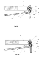
figures 2A ,2B et 2C représentent respectivement en perspective et en plan, dans une première position et dans une deuxième position, la butée rotative mobile assurant le passage des produits du convoyeur d'amenée sur la roue de prise, - la
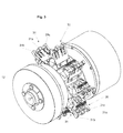
figure 3 est une vue en perspective illustrant la roue de prise agencée pour réceptionner les produits après leur transfert du convoyeur d'amenée, - les
figures 3A ,3B et 3C représentent des vues, respectivement en perspective, et en élévation d'une pince double de la roue de prise dans des positions différentes, pince de prise fermée et ouverte - les
figures 3D et 3E représentent des vues frontales en élévation d'une pince de la roue de prise dans des positions différentes, pince à papier ouverte et fermée - la
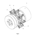
figure 4 est une vue en perspective de la roue d'emballage qui se situe, au niveau du processus de conditionnement après la roue de prise de lafigure 3 , - les
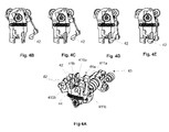
figures 4A, 4B, 4C, 4D et 4E représentent des vues, respectivement en perspective, et en élévation d'une pince double de la roue d'emballage dans des positions différentes, pince ouverte et fermée, rabatteur en position d'attente, intermédiaire et engagée - les
figures 5A, 5B, 5C, 5D et 5E illustrent les différentes étapes de l'emballage des produits, - la
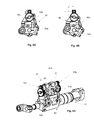
figure 6 est une vue en perspective de la roue de pivotement destinée à amener les produits emballés vers un module de scellage, - les
figures 6A, 6B et6C représentent des vues, respectivement en perspective, et en élévation d'une pince double de la roue de pivotement dans des positions différentes, pince de pivotement fermée et ouverte, - les
figures 6D et 6E représentent des vues frontales en élévation d'une pince de la roue de pivotement dans des positions différentes, avec le produit transporté non pivoté et pivoté, et - la
figure 7 est une vue schématique qui illustre l'étape finale du scellage de l'emballage, après les dernière phases de pliage.
- the
figure 1 is a view schematically illustrating as a whole, the device for implementing the various steps of the method according to the invention, - the
Figures 2A ,2B and 2C respectively show in perspective and in plan, in a first position and in a second position, the movable rotary stop ensuring the passage of the products of the supply conveyor on the setting wheel, - the
figure 3 is a perspective view illustrating the setting wheel arranged to receive the products after their transfer from the supply conveyor, - the
Figures 3A ,3B and 3C represent views, respectively in perspective, and in elevation of a double gripper of the gripping wheel in different positions, gripping gripper closed and open - the
3D and 3E figures represent front elevational views of a grab wheel gripper in different positions, open and closed paper clip - the
figure 4 is a perspective view of the packaging wheel which is located at the level of the conditioning process after the setting wheel of thefigure 3 , - the
FIGS. 4A, 4B, 4C, 4D and 4E represent views, respectively in perspective, and in elevation of a double gripper of the packaging wheel in different positions, open and closed gripper, reel in waiting position, intermediate and engaged - the
FIGS. 5A, 5B, 5C, 5D and 5E illustrate the different stages of product packaging, - the
figure 6 is a perspective view of the pivoting wheel for bringing the packaged products to a sealing module, - the
Figures 6A, 6B and6C represent views, respectively in perspective, and in elevation of a double gripper of the pivot wheel in different positions, closed and open pivoting pliers, - the
Figures 6D and 6E represent front elevational views of a gripper of the slewing wheel in different positions, with the product transported unrotated and rotated, and - the
figure 7 is a schematic view that illustrates the final step of sealing the package, after the last folding phases.
En référence aux figures, le procédé de l'invention, mis en oeuvre par la machine de conditionnement 10 selon l'invention telle qu' illustrée schématiquement dans son ensemble par la
On notera également qu'au cours de cette deuxième étape, à savoir le passage sur la roue de prise 12, un écart se forme entre les paires successives de produits A, immédiatement lors du passage sur la roue de prise, pour respecter ladite cinématique continue qui représente une spécificité de la machine décrite. Cet écart pourrait être obtenu de façon connue, grâce un différentiel entre la vitesse linéaire du convoyeur d'amenée 11 et la vitesse périphérique de la roue de prise 12, pour séparer les paires de produits, au moyen d'un jeu de rubans motorisés et munis de chambre à vide. Toutefois une telle solution connue engendrerait des accélérations importantes qui pourraient nuire à la stabilité de l'alimentation des produits. C'est pourquoi l'écart entre les paires de produits A est créé au moyen d'une butée mobile 13 (illustrée par les
Au cours d'une troisième étape, un dispositif d'approvisionnement en matériau d'emballage 15, amène deux demi-pièces prédécoupées mais non écartées 15a et 15b dudit matériau d'emballage 15, sous la forme d'un matériau composite et/ou de papier d'emballage, vers la périphérie de la roue de prise 12, plus précisément sur la trajectoire des produits A, en intersection avec cette trajectoire pour se retrouver sur la voie d'une des paires de produits A. Cette opération permet aux pièces du matériau d'emballage 15a et 15b de se replier partiellement autour du produit A et d'être entraînée avec lui en rotation sur la roue de prise 12. L'opération suivante est effectuée au cours d'une quatrième étape, les produits A associés aux pièces de matériau d'emballage 15a et 15b étant transférés sur une autre roue appelée roue d'emballage 16. La roue de prise 12 reçoit tangentiellement les paires de produits A et tourne dans le sens des aiguilles d'une montre, alors que la roue d'emballage 16 tourne dans le sens opposé, à savoir le sens contraire aux aiguilles d'une montre. Au cours de la rotation sur la roue d'emballage 16, les pièces de matériau d'emballage 15a et 15b respectivement associés aux produits A1 et A2 de chaque paire de produits cheminent avec la tête respectivement associée aux produits correspondants et sont soumises aux opérations de pliage par rabatteur frontal embarqué et fermeture des rabats latéraux par hélices fixes. A la fin de cette quatrième étape, les produits sont quasiment emballés sans, toutefois que les bords latéraux soient entièrement repliés et sans que ces derniers soient scellés.In a third step, a packaging
La cinquième étape consiste à reprendre les produits emballés de la roue d'emballage 16 sur une roue de basculement 17 qui tourne dans le sens opposé à la roue d'emballage 16, à savoir dans le sens des aiguilles d'une montre. La fonction de la roue de basculement 17 est de contrer le pivotement des produits en raison de la rotation naturelle de cette roue, afin de les maintenir dans une position adéquate pour permettre de terminer le pliage de l'emballage en vue du scellage final.The fifth step is to take the packaged products of the
Ces opérations sont effectuées au cours de l'étape suivante, à savoir la sixième étape qui consiste à faire passer les produits emballés de la roue de basculement 17 vers un module de scellage 18 dans le but de finir l'emballage des produits.These operations are carried out in the next step, namely the sixth step which consists of passing the packaged products of the
L'ensemble de ces opérations est rendu possible par la machine selon l'invention dont les différents composants sont illustrés et décrits ci-dessous.All of these operations are made possible by the machine according to the invention, the various components of which are illustrated and described below.
La machine 10 est équipée d'un dispositif d'amenée et de synchronisation 20 des produits A, situé entre la sortie de la presse (non représentée) et leur acheminement par le convoyeur 11 sur la roue de prise 12. Le dispositif d'amenée et de synchronisation 20 est monté sur un bâti fixe 21 disposé au-dessus d'un convoyeur (non représenté) qui transporte les produits par paires A1, A2 issus d'une unité de moulage-compression, ces produits étant juxtaposés selon deux colonnes parallèles 22, 23 sur un transporteur à bande (non représenté).The machine 10 is equipped with a device for supplying and synchronizing the products A, located between the exit of the press (not shown) and their conveyance by the
A l'extrémité libre du bâti 21 est monté un berceau 24 pivotant autour d'un axe 25 sur lequel est fixé un axe 26 portant une roue centrale 27 pourvue d'au moins deux et de préférence de trois paires de branches équidistantes 28. Les trois paires de branches équidistantes 28 constituent des pales d'appui 28a, 28b, 28c rotatives, deux à deux parallèles et destinées à servir respectivement de butées mobiles aux paires de produits A acheminés par le convoyeur d'amenée 11 et de les accompagner par paires sur la roue de prise 16 pendant que le berceau basculant 24 pivote sur son axe de pivotement 27 en vue d'accélérer le produit A lorsqu'il a été pris en charge par une des pales rotatives 28a, 28b ou 28c et de créer un espace entre le premier produit A arrivant sur une piste du convoyeur d'amenée 11 et le produit suivant A de la même piste du convoyeur d'amenée 11. Chacune des pales se met en place successivement avant l'arrivée d'un produit de telle manière que la colonne de produits n'est jamais arrêtée. Ce dispositif permet de traiter simultanément deux produits A, en l'occurrence A1 et A2 constituant une paire de produits respectivement acheminés sur les deux pistes parallèles du convoyeur d'amenée 11.At the free end of the
La
La
On remarquera la position d'un doigt de pince 29 solidaire de la roue de prise 12, restant toujours dans une position radiale et qui bascule relativement au berceau basculant 24 au cours de cette opération de passage des produits A du convoyeur 11 sur la roue de prise 12.The
Note the position of a
La
Les
La pince double 31 comporte un bras central fixe 31 a et deux bras latéraux 31 b et 31 c qui sont mobiles par rapport au bras central 31 a. Les deux éléments de la pince double 31 sont ouverts et peuvent recevoir chacun un produit A lorsque les bras latéraux 31 b et 31 c sont écartés du bras central 31 a et lorsque les bras latéraux se rapprochent ils ferment les éléments de la pince double sur les produits A correspondants et les maintiennent en position.The
Les
Les deux vues frontales 3D et 3E illustrent essentiellement une pince 33 dite pince à papier qui est destinée à prendre en passant une pièce de matériau d'emballage 15 se présentant sous la forme d'une feuille unique partiellement découpée adaptée à l'ensemble de deux produits A amenés par paires. La vue de la
La
La première fonction de la roue d'emballage 16 consiste à prendre les produits au vol au moyen de pinces 41 montées chacune sur une tête 40 qui oscille pour permettre la réduction et l'adaptation de la vitesse de défilement lors de la fermeture de la pince 41 correspondante au moment du transfert des produits A. La suite du traitement qui consiste à emballer complètement le produit jusqu'au rabat final de volets latéraux et au scellage du matériau d'emballage qui s'effectue sur la roue d'emballage 16 avec ses composants qui sont illustrés par les
La pince 41 est, comme la pince 31 de la roue de prise 12, une pince double et comporte en fait deux organes de pincement 41a et 41 b qui sont destinés respectivement à prendre en charge simultanément les produits A1 et A2 de la paire de produits A. Chaque organe de pincement 41 b est associé à deux rabatteurs 42 ayant pour fonction d'assurer le repli des rabats latéraux pendant le cheminement des produits sur ladite roue d'emballage 16.The
La
La
L'opération d'emballage du produit A comprend un certain nombre de phases qui sont illustrées par les
A la fin de l'emballage sur le roue d'emballage 16, les produits sont repris par une roue de basculement 17, illustrée par la
La
Les
Le module de scellage réceptionne les produits emballés A sur un guide longitudinal et ils sont entraînés par une bande transporteuse pourvue de taquets et disposée au-dessus de la ligne des produits pour assurer leur cheminement. Des rampes latérales sont ménagées sur les cotés pour replier les rabats latéraux en forme de pointe. Cette opération est illustrée par la
Claims (15)
Priority Applications (1)
| Application Number | Priority Date | Filing Date | Title |
|---|---|---|---|
| EP14196114.4A EP2894103B1 (en) | 2014-01-10 | 2014-12-03 | Method and device for packaging food products into individual portions |
Applications Claiming Priority (2)
| Application Number | Priority Date | Filing Date | Title |
|---|---|---|---|
| PCT/EP2014/050382 WO2015104057A1 (en) | 2014-01-10 | 2014-01-10 | Method and device for packaging food products in individual portions |
| EP14196114.4A EP2894103B1 (en) | 2014-01-10 | 2014-12-03 | Method and device for packaging food products into individual portions |
Publications (3)
| Publication Number | Publication Date |
|---|---|
| EP2894103A2 true EP2894103A2 (en) | 2015-07-15 |
| EP2894103A3 EP2894103A3 (en) | 2015-08-05 |
| EP2894103B1 EP2894103B1 (en) | 2016-09-07 |
Family
ID=53275938
Family Applications (1)
| Application Number | Title | Priority Date | Filing Date |
|---|---|---|---|
| EP14196114.4A Revoked EP2894103B1 (en) | 2014-01-10 | 2014-12-03 | Method and device for packaging food products into individual portions |
Country Status (1)
| Country | Link |
|---|---|
| EP (1) | EP2894103B1 (en) |
Cited By (8)
| Publication number | Priority date | Publication date | Assignee | Title |
|---|---|---|---|---|
| IT201800008201A1 (en) * | 2018-08-28 | 2020-02-28 | Mpm Srl | WRAPPING MACHINE FOR WRAPPING SOUP NUTS |
| IT201800010315A1 (en) * | 2018-11-14 | 2020-05-14 | Gd Spa | Wrapping method to make two packages at the same time |
| IT201800010313A1 (en) * | 2018-11-14 | 2020-05-14 | Gd Spa | Method and unit of feeding two sheets of wrapping into a packing machine |
| IT201800010592A1 (en) * | 2018-11-27 | 2020-05-27 | Corazza S P A | MACHINE FOR THE PACKAGING OF SOLID FOOD PRODUCTS. |
| EP3763644A1 (en) * | 2019-07-12 | 2021-01-13 | Theegarten-Pactec GmbH & Co. KG | Rotary head with rotating work stations |
| EP3858746A1 (en) | 2020-01-30 | 2021-08-04 | Theegarten-Pactec GmbH & Co. KG | Method and device for packaging and sealing small articles on three continuously rotating heads |
| IT202100010931A1 (en) * | 2021-04-29 | 2022-10-29 | Ima Spa | EQUIPMENT AND PROCEDURE FOR PACKAGING PRODUCTS |
| EP4209425A1 (en) * | 2021-12-17 | 2023-07-12 | Theegarten-Pactec GmbH & Co. KG | Device and method for packaging small-sized articles with creation and optional features. securing overlapping packaging means folds |
Family Cites Families (22)
| Publication number | Priority date | Publication date | Assignee | Title |
|---|---|---|---|---|
| JPS5834325B2 (en) * | 1977-12-24 | 1983-07-26 | 株式会社ロツテ | Packaging method and device for plate-shaped articles |
| CH621981A5 (en) | 1977-12-29 | 1981-03-13 | Sig Schweiz Industrieges | |
| DE3332950A1 (en) | 1983-09-13 | 1985-03-28 | Focke & Co, 2810 Verden | METHOD AND DEVICE FOR ENHANCING CIGARETTE PACKS IN FILM CUTS |
| DE3639994A1 (en) | 1986-11-22 | 1988-05-26 | Focke & Co | PACKING MACHINE, IN PARTICULAR FOR CIGARETTE PACKS |
| DE3802644C2 (en) | 1988-01-29 | 1999-10-07 | Focke & Co | Method and device for manufacturing folding boxes for cigarettes |
| IT1266231B1 (en) | 1993-01-29 | 1996-12-27 | Azionaria Costruzioni Acma Spa | WRAPPING METHOD AND MACHINE, PARTICULARLY FOR FOOD PRODUCTS SUCH AS CHOCOLATES AND SIMILAR. |
| DE9422350U1 (en) | 1993-01-29 | 2000-08-17 | Azionaria Costruzioni Acma Spa | Wrapping device, in particular for foods such as confectionery or the like. |
| DE19642014B4 (en) * | 1996-10-11 | 2005-08-04 | Pactec Verpackungsmaschinen-Fabrik Theegarten Gmbh & Co. Kg | Device for packing small-sized articles in the fold wrapping |
| DE19726324A1 (en) * | 1997-06-20 | 1998-12-24 | Focke & Co | Method and device for manufacturing hinged boxes |
| DE19920710B4 (en) | 1999-05-05 | 2010-07-01 | Theegarten-Pactec Gmbh & Co. Kg | Device for packaging small-sized articles |
| IT1311107B1 (en) | 1999-10-22 | 2002-02-28 | Ohg Natalino Corazza S P A | APPARATUS FOR THE PACKAGING OF A FOOD PRODUCT, IN PARTICULAR A PASTY FOOD PRODUCT. |
| ITBO20020220A1 (en) * | 2002-04-23 | 2003-10-23 | Azionaria Costruzioni Acma Spa | MACHINE FOR THE WRAPPING OF PRODUCTS |
| DE102005017329B4 (en) | 2005-04-14 | 2014-10-16 | Theegarten-Pactec Gmbh & Co. Kg | Method and device for packaging small-sized articles |
| DE202006020630U1 (en) | 2006-05-03 | 2009-04-02 | Robert Bosch Gmbh | Machine for packaging small-sized confectionery |
| ITBO20060682A1 (en) | 2006-10-03 | 2008-04-04 | Sympak Corazza S P A | EQUIPMENT FOR PACKAGING A PRODUCT. |
| ITBO20070028A1 (en) | 2007-01-19 | 2008-07-20 | Rc S P A | DEVICE FOR THE PREPARATION OF A PRODUCT PACKAGE. |
| DE102008019605A1 (en) * | 2008-04-18 | 2009-10-22 | Theegarten Pactec Gmbh & Co. Kg | Process for packaging small-sized articles, in particular chocolate-coated pralines or caramels, in a continuous mode of operation and packaging machine, in particular for carrying out the method |
| IT1394664B1 (en) * | 2009-06-05 | 2012-07-13 | Azionaria Costruzioni Acma Spa | TABLETING MACHINE FOR FOOD PRODUCTS |
| DE102010053872C5 (en) | 2010-12-09 | 2019-10-17 | Multivac Sepp Haggenmüller Se & Co. Kg | Packaging plant with sorting station |
| ITBO20120031A1 (en) * | 2012-01-26 | 2012-04-26 | Gd Spa | WRAPPING MACHINE AND WRAPPING METHOD TO CREATE A PACKAGE OF SMOKE ITEMS WITH SLIDING OPENING AND WITH HINGED AND BOILED LID. |
| EP2626305B1 (en) * | 2012-02-09 | 2015-01-07 | G.D Societa' Per Azioni | Packing machine and method for producing rigid packets, each comprising at least two containers one inside the other |
| DE102012019909A1 (en) | 2012-10-11 | 2014-04-17 | Theegarten-Pactec Gmbh & Co. Kg | High-performance packaging method for packaging, in particular small-sized, products and high-performance packaging device, in particular for carrying out the method |
-
2014
- 2014-12-03 EP EP14196114.4A patent/EP2894103B1/en not_active Revoked
Non-Patent Citations (1)
| Title |
|---|
| None |
Cited By (12)
| Publication number | Priority date | Publication date | Assignee | Title |
|---|---|---|---|---|
| IT201800008201A1 (en) * | 2018-08-28 | 2020-02-28 | Mpm Srl | WRAPPING MACHINE FOR WRAPPING SOUP NUTS |
| IT201800010315A1 (en) * | 2018-11-14 | 2020-05-14 | Gd Spa | Wrapping method to make two packages at the same time |
| IT201800010313A1 (en) * | 2018-11-14 | 2020-05-14 | Gd Spa | Method and unit of feeding two sheets of wrapping into a packing machine |
| EP3653518A1 (en) * | 2018-11-14 | 2020-05-20 | G.D Societa' Per Azioni | Feeding method and unit to feed two wrapping sheets in a packing machine |
| IT201800010592A1 (en) * | 2018-11-27 | 2020-05-27 | Corazza S P A | MACHINE FOR THE PACKAGING OF SOLID FOOD PRODUCTS. |
| WO2020109905A1 (en) * | 2018-11-27 | 2020-06-04 | Corazza S.P.A. | Device for feeding and arranging solid food products and machine for packaging solid food products |
| EP3763644A1 (en) * | 2019-07-12 | 2021-01-13 | Theegarten-Pactec GmbH & Co. KG | Rotary head with rotating work stations |
| EP3858746A1 (en) | 2020-01-30 | 2021-08-04 | Theegarten-Pactec GmbH & Co. KG | Method and device for packaging and sealing small articles on three continuously rotating heads |
| DE102020201099A1 (en) | 2020-01-30 | 2021-08-05 | Theegarten PACTEC GmbH & Co.KG | Method and device for packaging and sealing small-sized products on three continuously rotating working heads |
| IT202100010931A1 (en) * | 2021-04-29 | 2022-10-29 | Ima Spa | EQUIPMENT AND PROCEDURE FOR PACKAGING PRODUCTS |
| WO2022230000A1 (en) * | 2021-04-29 | 2022-11-03 | I.M.A. Industria Macchine Automatiche S.P.A. | Apparatus and method for packaging products |
| EP4209425A1 (en) * | 2021-12-17 | 2023-07-12 | Theegarten-Pactec GmbH & Co. KG | Device and method for packaging small-sized articles with creation and optional features. securing overlapping packaging means folds |
Also Published As
| Publication number | Publication date |
|---|---|
| EP2894103B1 (en) | 2016-09-07 |
| EP2894103A3 (en) | 2015-08-05 |
Similar Documents
| Publication | Publication Date | Title |
|---|---|---|
| EP2894103B1 (en) | Method and device for packaging food products into individual portions | |
| EP0295203B1 (en) | Method for packaging a product, and device for carrying out the method | |
| EP2341001B1 (en) | Method and machine for overpackaging items in order to form batches of items, including a certain plurality of items and a cardboard overpackaging | |
| EP3038954B1 (en) | Method for transporting and turning flat objects | |
| FR2642039A1 (en) | METHOD AND DEVICE FOR CONTINUOUS FEEDING OF FLANS | |
| FR2907369A1 (en) | METHOD AND INSTALLATION FOR THE PREPARATION OF A COMPOSITE BOX | |
| EP2648978B1 (en) | Boxing method and device intended to sequentially box batches of products inside packaging receptacles | |
| EP2688805B1 (en) | Method for packaging products, particularly portions of chocolate or the like, and facility for implementing the method | |
| EP2117809B1 (en) | Device and method for thermoforming decorated vessels in order to place bottom labels on thermoformed vessels | |
| FR2855147A1 (en) | Products e.g. cigarette packet, packing process for tobacco industry, involves routing components of packing material and sheet within holding apparatus that is associated to radial seat of wheel and mounted on wheel | |
| EP2632805B1 (en) | Device and method for overwrapping identical or similar products and boxing the overwrapped products | |
| EP1675734B1 (en) | Method for the automatic enveloping of small items, such as documents, and device used to implement same | |
| WO2015104057A1 (en) | Method and device for packaging food products in individual portions | |
| FR2639614A1 (en) | PROCESS FOR PACKING CIGARETTES IN HARD PACKETS WITH ABOVE | |
| FR2649953A1 (en) | PACKING MACHINE, IN BOXES, GROUPS OF ARTICLES | |
| WO2019243732A1 (en) | Label affixing machine with indexing | |
| WO2021052961A1 (en) | Device and method for forming a container by folding | |
| WO2014154333A1 (en) | Device for pivoting flat objects | |
| EP2143645B1 (en) | Method and device for supplying a machine for packaging food products with individual portions | |
| FR2482046A1 (en) | DEVICE FOR MAKING A CARDBOARD FLAN AN OPEN TUBULAR SHAPE | |
| WO2000043268A1 (en) | Method and installation for producing and continuously filling flexible receptacles | |
| EP4327994A1 (en) | Method for production of packaging blanks and corresponding module | |
| EP4134313A1 (en) | Method and machine for filling goatskins | |
| FR3077279A3 (en) | Multi-format conveyor for a machine for packing articles in containers | |
| FR3101858A1 (en) | Folding container forming device and method |
Legal Events
| Date | Code | Title | Description |
|---|---|---|---|
| PUAL | Search report despatched |
Free format text: ORIGINAL CODE: 0009013 |
|
| PUAI | Public reference made under article 153(3) epc to a published international application that has entered the european phase |
Free format text: ORIGINAL CODE: 0009012 |
|
| 17P | Request for examination filed |
Effective date: 20141203 |
|
| AK | Designated contracting states |
Kind code of ref document: A2 Designated state(s): AL AT BE BG CH CY CZ DE DK EE ES FI FR GB GR HR HU IE IS IT LI LT LU LV MC MK MT NL NO PL PT RO RS SE SI SK SM TR |
|
| AX | Request for extension of the european patent |
Extension state: BA ME |
|
| AK | Designated contracting states |
Kind code of ref document: A3 Designated state(s): AL AT BE BG CH CY CZ DE DK EE ES FI FR GB GR HR HU IE IS IT LI LT LU LV MC MK MT NL NO PL PT RO RS SE SI SK SM TR |
|
| AX | Request for extension of the european patent |
Extension state: BA ME |
|
| RIC1 | Information provided on ipc code assigned before grant |
Ipc: B65B 25/06 20060101ALI20150626BHEP Ipc: B65B 61/02 20060101ALI20150626BHEP Ipc: B65B 11/46 20060101ALI20150626BHEP Ipc: B65B 65/00 20060101AFI20150626BHEP Ipc: B65B 41/02 20060101ALI20150626BHEP |
|
| R17P | Request for examination filed (corrected) |
Effective date: 20160205 |
|
| RBV | Designated contracting states (corrected) |
Designated state(s): AL AT BE BG CH CY CZ DE DK EE ES FI FR GB GR HR HU IE IS IT LI LT LU LV MC MK MT NL NO PL PT RO RS SE SI SK SM TR |
|
| GRAP | Despatch of communication of intention to grant a patent |
Free format text: ORIGINAL CODE: EPIDOSNIGR1 |
|
| INTG | Intention to grant announced |
Effective date: 20160602 |
|
| GRAS | Grant fee paid |
Free format text: ORIGINAL CODE: EPIDOSNIGR3 |
|
| GRAA | (expected) grant |
Free format text: ORIGINAL CODE: 0009210 |
|
| STAA | Information on the status of an ep patent application or granted ep patent |
Free format text: STATUS: THE PATENT HAS BEEN GRANTED |
|
| AK | Designated contracting states |
Kind code of ref document: B1 Designated state(s): AL AT BE BG CH CY CZ DE DK EE ES FI FR GB GR HR HU IE IS IT LI LT LU LV MC MK MT NL NO PL PT RO RS SE SI SK SM TR |
|
| REG | Reference to a national code |
Ref country code: GB Ref legal event code: FG4D Free format text: NOT ENGLISH |
|
| REG | Reference to a national code |
Ref country code: CH Ref legal event code: EP |
|
| REG | Reference to a national code |
Ref country code: IE Ref legal event code: FG4D Free format text: LANGUAGE OF EP DOCUMENT: FRENCH |
|
| REG | Reference to a national code |
Ref country code: AT Ref legal event code: REF Ref document number: 826610 Country of ref document: AT Kind code of ref document: T Effective date: 20161015 |
|
| REG | Reference to a national code |
Ref country code: DE Ref legal event code: R096 Ref document number: 602014003512 Country of ref document: DE |
|
| REG | Reference to a national code |
Ref country code: LT Ref legal event code: MG4D |
|
| REG | Reference to a national code |
Ref country code: NL Ref legal event code: MP Effective date: 20160907 |
|
| PG25 | Lapsed in a contracting state [announced via postgrant information from national office to epo] |
Ref country code: LT Free format text: LAPSE BECAUSE OF FAILURE TO SUBMIT A TRANSLATION OF THE DESCRIPTION OR TO PAY THE FEE WITHIN THE PRESCRIBED TIME-LIMIT Effective date: 20160907 Ref country code: FI Free format text: LAPSE BECAUSE OF FAILURE TO SUBMIT A TRANSLATION OF THE DESCRIPTION OR TO PAY THE FEE WITHIN THE PRESCRIBED TIME-LIMIT Effective date: 20160907 Ref country code: HR Free format text: LAPSE BECAUSE OF FAILURE TO SUBMIT A TRANSLATION OF THE DESCRIPTION OR TO PAY THE FEE WITHIN THE PRESCRIBED TIME-LIMIT Effective date: 20160907 Ref country code: RS Free format text: LAPSE BECAUSE OF FAILURE TO SUBMIT A TRANSLATION OF THE DESCRIPTION OR TO PAY THE FEE WITHIN THE PRESCRIBED TIME-LIMIT Effective date: 20160907 Ref country code: NO Free format text: LAPSE BECAUSE OF FAILURE TO SUBMIT A TRANSLATION OF THE DESCRIPTION OR TO PAY THE FEE WITHIN THE PRESCRIBED TIME-LIMIT Effective date: 20161207 |
|
| REG | Reference to a national code |
Ref country code: AT Ref legal event code: MK05 Ref document number: 826610 Country of ref document: AT Kind code of ref document: T Effective date: 20160907 |
|
| PG25 | Lapsed in a contracting state [announced via postgrant information from national office to epo] |
Ref country code: GR Free format text: LAPSE BECAUSE OF FAILURE TO SUBMIT A TRANSLATION OF THE DESCRIPTION OR TO PAY THE FEE WITHIN THE PRESCRIBED TIME-LIMIT Effective date: 20161208 Ref country code: ES Free format text: LAPSE BECAUSE OF FAILURE TO SUBMIT A TRANSLATION OF THE DESCRIPTION OR TO PAY THE FEE WITHIN THE PRESCRIBED TIME-LIMIT Effective date: 20160907 Ref country code: NL Free format text: LAPSE BECAUSE OF FAILURE TO SUBMIT A TRANSLATION OF THE DESCRIPTION OR TO PAY THE FEE WITHIN THE PRESCRIBED TIME-LIMIT Effective date: 20160907 Ref country code: LV Free format text: LAPSE BECAUSE OF FAILURE TO SUBMIT A TRANSLATION OF THE DESCRIPTION OR TO PAY THE FEE WITHIN THE PRESCRIBED TIME-LIMIT Effective date: 20160907 Ref country code: SE Free format text: LAPSE BECAUSE OF FAILURE TO SUBMIT A TRANSLATION OF THE DESCRIPTION OR TO PAY THE FEE WITHIN THE PRESCRIBED TIME-LIMIT Effective date: 20160907 |
|
| PG25 | Lapsed in a contracting state [announced via postgrant information from national office to epo] |
Ref country code: EE Free format text: LAPSE BECAUSE OF FAILURE TO SUBMIT A TRANSLATION OF THE DESCRIPTION OR TO PAY THE FEE WITHIN THE PRESCRIBED TIME-LIMIT Effective date: 20160907 Ref country code: RO Free format text: LAPSE BECAUSE OF FAILURE TO SUBMIT A TRANSLATION OF THE DESCRIPTION OR TO PAY THE FEE WITHIN THE PRESCRIBED TIME-LIMIT Effective date: 20160907 |
|
| PG25 | Lapsed in a contracting state [announced via postgrant information from national office to epo] |
Ref country code: AT Free format text: LAPSE BECAUSE OF FAILURE TO SUBMIT A TRANSLATION OF THE DESCRIPTION OR TO PAY THE FEE WITHIN THE PRESCRIBED TIME-LIMIT Effective date: 20160907 Ref country code: PT Free format text: LAPSE BECAUSE OF FAILURE TO SUBMIT A TRANSLATION OF THE DESCRIPTION OR TO PAY THE FEE WITHIN THE PRESCRIBED TIME-LIMIT Effective date: 20170109 Ref country code: BG Free format text: LAPSE BECAUSE OF FAILURE TO SUBMIT A TRANSLATION OF THE DESCRIPTION OR TO PAY THE FEE WITHIN THE PRESCRIBED TIME-LIMIT Effective date: 20161207 Ref country code: SM Free format text: LAPSE BECAUSE OF FAILURE TO SUBMIT A TRANSLATION OF THE DESCRIPTION OR TO PAY THE FEE WITHIN THE PRESCRIBED TIME-LIMIT Effective date: 20160907 Ref country code: BE Free format text: LAPSE BECAUSE OF NON-PAYMENT OF DUE FEES Effective date: 20161231 Ref country code: SK Free format text: LAPSE BECAUSE OF FAILURE TO SUBMIT A TRANSLATION OF THE DESCRIPTION OR TO PAY THE FEE WITHIN THE PRESCRIBED TIME-LIMIT Effective date: 20160907 Ref country code: PL Free format text: LAPSE BECAUSE OF FAILURE TO SUBMIT A TRANSLATION OF THE DESCRIPTION OR TO PAY THE FEE WITHIN THE PRESCRIBED TIME-LIMIT Effective date: 20160907 Ref country code: IS Free format text: LAPSE BECAUSE OF FAILURE TO SUBMIT A TRANSLATION OF THE DESCRIPTION OR TO PAY THE FEE WITHIN THE PRESCRIBED TIME-LIMIT Effective date: 20170107 Ref country code: CZ Free format text: LAPSE BECAUSE OF FAILURE TO SUBMIT A TRANSLATION OF THE DESCRIPTION OR TO PAY THE FEE WITHIN THE PRESCRIBED TIME-LIMIT Effective date: 20160907 |
|
| REG | Reference to a national code |
Ref country code: DE Ref legal event code: R026 Ref document number: 602014003512 Country of ref document: DE |
|
| PLBI | Opposition filed |
Free format text: ORIGINAL CODE: 0009260 |
|
| PLAN | Information deleted related to communication of a notice of opposition and request to file observations + time limit |
Free format text: ORIGINAL CODE: EPIDOSDOBS2 |
|
| PLAX | Notice of opposition and request to file observation + time limit sent |
Free format text: ORIGINAL CODE: EPIDOSNOBS2 |
|
| 26 | Opposition filed |
Opponent name: THEEGARTEN-PACTEC GMBH & CO. KG Effective date: 20170606 |
|
| PLAX | Notice of opposition and request to file observation + time limit sent |
Free format text: ORIGINAL CODE: EPIDOSNOBS2 |
|
| PG25 | Lapsed in a contracting state [announced via postgrant information from national office to epo] |
Ref country code: DK Free format text: LAPSE BECAUSE OF FAILURE TO SUBMIT A TRANSLATION OF THE DESCRIPTION OR TO PAY THE FEE WITHIN THE PRESCRIBED TIME-LIMIT Effective date: 20160907 |
|
| PG25 | Lapsed in a contracting state [announced via postgrant information from national office to epo] |
Ref country code: SI Free format text: LAPSE BECAUSE OF FAILURE TO SUBMIT A TRANSLATION OF THE DESCRIPTION OR TO PAY THE FEE WITHIN THE PRESCRIBED TIME-LIMIT Effective date: 20160907 |
|
| PG25 | Lapsed in a contracting state [announced via postgrant information from national office to epo] |
Ref country code: MC Free format text: LAPSE BECAUSE OF FAILURE TO SUBMIT A TRANSLATION OF THE DESCRIPTION OR TO PAY THE FEE WITHIN THE PRESCRIBED TIME-LIMIT Effective date: 20160907 |
|
| REG | Reference to a national code |
Ref country code: FR Ref legal event code: ST Effective date: 20170831 |
|
| REG | Reference to a national code |
Ref country code: IE Ref legal event code: MM4A |
|
| PG25 | Lapsed in a contracting state [announced via postgrant information from national office to epo] |
Ref country code: FR Free format text: LAPSE BECAUSE OF NON-PAYMENT OF DUE FEES Effective date: 20170102 Ref country code: LU Free format text: LAPSE BECAUSE OF NON-PAYMENT OF DUE FEES Effective date: 20161203 |
|
| PLBB | Reply of patent proprietor to notice(s) of opposition received |
Free format text: ORIGINAL CODE: EPIDOSNOBS3 |
|
| PG25 | Lapsed in a contracting state [announced via postgrant information from national office to epo] |
Ref country code: IE Free format text: LAPSE BECAUSE OF NON-PAYMENT OF DUE FEES Effective date: 20161203 |
|
| REG | Reference to a national code |
Ref country code: BE Ref legal event code: MM Effective date: 20161231 |
|
| PG25 | Lapsed in a contracting state [announced via postgrant information from national office to epo] |
Ref country code: HU Free format text: LAPSE BECAUSE OF FAILURE TO SUBMIT A TRANSLATION OF THE DESCRIPTION OR TO PAY THE FEE WITHIN THE PRESCRIBED TIME-LIMIT; INVALID AB INITIO Effective date: 20141203 |
|
| REG | Reference to a national code |
Ref country code: DE Ref legal event code: R081 Ref document number: 602014003512 Country of ref document: DE Owner name: SAPAL SA, CH Free format text: FORMER OWNER: ROBERT BOSCH GMBH, 70469 STUTTGART, DE |
|
| REG | Reference to a national code |
Ref country code: CH Ref legal event code: PUE Owner name: SAPAL SA, CH Free format text: FORMER OWNER: ROBERT BOSCH GMBH, DE Ref country code: CH Ref legal event code: NV Representative=s name: CABINET ROLAND NITHARDT CONSEILS EN PROPRIETE , CH |
|
| PG25 | Lapsed in a contracting state [announced via postgrant information from national office to epo] |
Ref country code: MK Free format text: LAPSE BECAUSE OF FAILURE TO SUBMIT A TRANSLATION OF THE DESCRIPTION OR TO PAY THE FEE WITHIN THE PRESCRIBED TIME-LIMIT Effective date: 20160907 Ref country code: CY Free format text: LAPSE BECAUSE OF FAILURE TO SUBMIT A TRANSLATION OF THE DESCRIPTION OR TO PAY THE FEE WITHIN THE PRESCRIBED TIME-LIMIT Effective date: 20160907 |
|
| RAP2 | Party data changed (patent owner data changed or rights of a patent transferred) |
Owner name: SAPAL SA |
|
| PG25 | Lapsed in a contracting state [announced via postgrant information from national office to epo] |
Ref country code: MT Free format text: LAPSE BECAUSE OF FAILURE TO SUBMIT A TRANSLATION OF THE DESCRIPTION OR TO PAY THE FEE WITHIN THE PRESCRIBED TIME-LIMIT Effective date: 20160907 |
|
| PG25 | Lapsed in a contracting state [announced via postgrant information from national office to epo] |
Ref country code: TR Free format text: LAPSE BECAUSE OF FAILURE TO SUBMIT A TRANSLATION OF THE DESCRIPTION OR TO PAY THE FEE WITHIN THE PRESCRIBED TIME-LIMIT Effective date: 20160907 Ref country code: AL Free format text: LAPSE BECAUSE OF FAILURE TO SUBMIT A TRANSLATION OF THE DESCRIPTION OR TO PAY THE FEE WITHIN THE PRESCRIBED TIME-LIMIT Effective date: 20160907 |
|
| RDAF | Communication despatched that patent is revoked |
Free format text: ORIGINAL CODE: EPIDOSNREV1 |
|
| STAA | Information on the status of an ep patent application or granted ep patent |
Free format text: STATUS: THE PATENT HAS BEEN GRANTED |
|
| APAH | Appeal reference modified |
Free format text: ORIGINAL CODE: EPIDOSCREFNO |
|
| APBM | Appeal reference recorded |
Free format text: ORIGINAL CODE: EPIDOSNREFNO |
|
| APBP | Date of receipt of notice of appeal recorded |
Free format text: ORIGINAL CODE: EPIDOSNNOA2O |
|
| APBQ | Date of receipt of statement of grounds of appeal recorded |
Free format text: ORIGINAL CODE: EPIDOSNNOA3O |
|
| GBPC | Gb: european patent ceased through non-payment of renewal fee |
Effective date: 20181203 |
|
| PG25 | Lapsed in a contracting state [announced via postgrant information from national office to epo] |
Ref country code: GB Free format text: LAPSE BECAUSE OF NON-PAYMENT OF DUE FEES Effective date: 20181203 |
|
| PGFP | Annual fee paid to national office [announced via postgrant information from national office to epo] |
Ref country code: IT Payment date: 20201201 Year of fee payment: 7 Ref country code: DE Payment date: 20201216 Year of fee payment: 7 |
|
| PGFP | Annual fee paid to national office [announced via postgrant information from national office to epo] |
Ref country code: CH Payment date: 20210318 Year of fee payment: 7 |
|
| REG | Reference to a national code |
Ref country code: DE Ref legal event code: R103 Ref document number: 602014003512 Country of ref document: DE Ref country code: DE Ref legal event code: R064 Ref document number: 602014003512 Country of ref document: DE |
|
| APBU | Appeal procedure closed |
Free format text: ORIGINAL CODE: EPIDOSNNOA9O |
|
| RDAG | Patent revoked |
Free format text: ORIGINAL CODE: 0009271 |
|
| STAA | Information on the status of an ep patent application or granted ep patent |
Free format text: STATUS: PATENT REVOKED |
|
| REG | Reference to a national code |
Ref country code: CH Ref legal event code: PL |
|
| REG | Reference to a national code |
Ref country code: FI Ref legal event code: MGE |
|
| 27W | Patent revoked |
Effective date: 20210608 |