EP2893964B1 - Purification device including continuous reactor and purification method using continuous reactor - Google Patents
Purification device including continuous reactor and purification method using continuous reactor Download PDFInfo
- Publication number
- EP2893964B1 EP2893964B1 EP13833620.1A EP13833620A EP2893964B1 EP 2893964 B1 EP2893964 B1 EP 2893964B1 EP 13833620 A EP13833620 A EP 13833620A EP 2893964 B1 EP2893964 B1 EP 2893964B1
- Authority
- EP
- European Patent Office
- Prior art keywords
- solution
- tryptophan
- storage tank
- thermal fluid
- continuous reactor
- Prior art date
- Legal status (The legal status is an assumption and is not a legal conclusion. Google has not performed a legal analysis and makes no representation as to the accuracy of the status listed.)
- Active
Links
Images






Classifications
-
- B—PERFORMING OPERATIONS; TRANSPORTING
- B01—PHYSICAL OR CHEMICAL PROCESSES OR APPARATUS IN GENERAL
- B01J—CHEMICAL OR PHYSICAL PROCESSES, e.g. CATALYSIS OR COLLOID CHEMISTRY; THEIR RELEVANT APPARATUS
- B01J19/00—Chemical, physical or physico-chemical processes in general; Their relevant apparatus
- B01J19/08—Processes employing the direct application of electric or wave energy, or particle radiation; Apparatus therefor
- B01J19/10—Processes employing the direct application of electric or wave energy, or particle radiation; Apparatus therefor employing sonic or ultrasonic vibrations
-
- B—PERFORMING OPERATIONS; TRANSPORTING
- B01—PHYSICAL OR CHEMICAL PROCESSES OR APPARATUS IN GENERAL
- B01D—SEPARATION
- B01D36/00—Filter circuits or combinations of filters with other separating devices
-
- B—PERFORMING OPERATIONS; TRANSPORTING
- B01—PHYSICAL OR CHEMICAL PROCESSES OR APPARATUS IN GENERAL
- B01D—SEPARATION
- B01D9/00—Crystallisation
-
- B—PERFORMING OPERATIONS; TRANSPORTING
- B01—PHYSICAL OR CHEMICAL PROCESSES OR APPARATUS IN GENERAL
- B01D—SEPARATION
- B01D9/00—Crystallisation
- B01D9/005—Selection of auxiliary, e.g. for control of crystallisation nuclei, of crystal growth, of adherence to walls; Arrangements for introduction thereof
- B01D9/0054—Use of anti-solvent
-
- B—PERFORMING OPERATIONS; TRANSPORTING
- B01—PHYSICAL OR CHEMICAL PROCESSES OR APPARATUS IN GENERAL
- B01D—SEPARATION
- B01D9/00—Crystallisation
- B01D9/0063—Control or regulation
-
- B—PERFORMING OPERATIONS; TRANSPORTING
- B01—PHYSICAL OR CHEMICAL PROCESSES OR APPARATUS IN GENERAL
- B01D—SEPARATION
- B01D9/00—Crystallisation
- B01D9/0081—Use of vibrations, e.g. ultrasound
-
- B—PERFORMING OPERATIONS; TRANSPORTING
- B01—PHYSICAL OR CHEMICAL PROCESSES OR APPARATUS IN GENERAL
- B01J—CHEMICAL OR PHYSICAL PROCESSES, e.g. CATALYSIS OR COLLOID CHEMISTRY; THEIR RELEVANT APPARATUS
- B01J19/00—Chemical, physical or physico-chemical processes in general; Their relevant apparatus
- B01J19/0006—Controlling or regulating processes
- B01J19/0013—Controlling the temperature of the process
-
- B—PERFORMING OPERATIONS; TRANSPORTING
- B01—PHYSICAL OR CHEMICAL PROCESSES OR APPARATUS IN GENERAL
- B01J—CHEMICAL OR PHYSICAL PROCESSES, e.g. CATALYSIS OR COLLOID CHEMISTRY; THEIR RELEVANT APPARATUS
- B01J19/00—Chemical, physical or physico-chemical processes in general; Their relevant apparatus
- B01J19/18—Stationary reactors having moving elements inside
-
- C—CHEMISTRY; METALLURGY
- C07—ORGANIC CHEMISTRY
- C07D—HETEROCYCLIC COMPOUNDS
- C07D209/00—Heterocyclic compounds containing five-membered rings, condensed with other rings, with one nitrogen atom as the only ring hetero atom
- C07D209/02—Heterocyclic compounds containing five-membered rings, condensed with other rings, with one nitrogen atom as the only ring hetero atom condensed with one carbocyclic ring
- C07D209/04—Indoles; Hydrogenated indoles
- C07D209/10—Indoles; Hydrogenated indoles with substituted hydrocarbon radicals attached to carbon atoms of the hetero ring
- C07D209/14—Radicals substituted by nitrogen atoms, not forming part of a nitro radical
- C07D209/16—Tryptamines
-
- C—CHEMISTRY; METALLURGY
- C07—ORGANIC CHEMISTRY
- C07D—HETEROCYCLIC COMPOUNDS
- C07D209/00—Heterocyclic compounds containing five-membered rings, condensed with other rings, with one nitrogen atom as the only ring hetero atom
- C07D209/02—Heterocyclic compounds containing five-membered rings, condensed with other rings, with one nitrogen atom as the only ring hetero atom condensed with one carbocyclic ring
- C07D209/04—Indoles; Hydrogenated indoles
- C07D209/10—Indoles; Hydrogenated indoles with substituted hydrocarbon radicals attached to carbon atoms of the hetero ring
- C07D209/18—Radicals substituted by carbon atoms having three bonds to hetero atoms with at the most one bond to halogen, e.g. ester or nitrile radicals
- C07D209/20—Radicals substituted by carbon atoms having three bonds to hetero atoms with at the most one bond to halogen, e.g. ester or nitrile radicals substituted additionally by nitrogen atoms, e.g. tryptophane
-
- B—PERFORMING OPERATIONS; TRANSPORTING
- B01—PHYSICAL OR CHEMICAL PROCESSES OR APPARATUS IN GENERAL
- B01D—SEPARATION
- B01D9/00—Crystallisation
- B01D2009/0086—Processes or apparatus therefor
- B01D2009/009—Separation of organic compounds by selective or extractive crystallisation with the aid of auxiliary substances forming complex or molecular compounds, e.g. with ureum, thioureum or metal salts
- B01D2009/0095—Separation of organic compounds by selective or extractive crystallisation with the aid of auxiliary substances forming complex or molecular compounds, e.g. with ureum, thioureum or metal salts with the aid of other complex forming substances than ureum, thioureum or metal salts
-
- B—PERFORMING OPERATIONS; TRANSPORTING
- B01—PHYSICAL OR CHEMICAL PROCESSES OR APPARATUS IN GENERAL
- B01J—CHEMICAL OR PHYSICAL PROCESSES, e.g. CATALYSIS OR COLLOID CHEMISTRY; THEIR RELEVANT APPARATUS
- B01J2219/00—Chemical, physical or physico-chemical processes in general; Their relevant apparatus
- B01J2219/00002—Chemical plants
- B01J2219/00027—Process aspects
- B01J2219/00033—Continuous processes
-
- B—PERFORMING OPERATIONS; TRANSPORTING
- B01—PHYSICAL OR CHEMICAL PROCESSES OR APPARATUS IN GENERAL
- B01J—CHEMICAL OR PHYSICAL PROCESSES, e.g. CATALYSIS OR COLLOID CHEMISTRY; THEIR RELEVANT APPARATUS
- B01J2219/00—Chemical, physical or physico-chemical processes in general; Their relevant apparatus
- B01J2219/00049—Controlling or regulating processes
- B01J2219/00051—Controlling the temperature
- B01J2219/00074—Controlling the temperature by indirect heating or cooling employing heat exchange fluids
- B01J2219/00087—Controlling the temperature by indirect heating or cooling employing heat exchange fluids with heat exchange elements outside the reactor
- B01J2219/00094—Jackets
-
- B—PERFORMING OPERATIONS; TRANSPORTING
- B01—PHYSICAL OR CHEMICAL PROCESSES OR APPARATUS IN GENERAL
- B01J—CHEMICAL OR PHYSICAL PROCESSES, e.g. CATALYSIS OR COLLOID CHEMISTRY; THEIR RELEVANT APPARATUS
- B01J2219/00—Chemical, physical or physico-chemical processes in general; Their relevant apparatus
- B01J2219/00049—Controlling or regulating processes
- B01J2219/00051—Controlling the temperature
- B01J2219/00074—Controlling the temperature by indirect heating or cooling employing heat exchange fluids
- B01J2219/00087—Controlling the temperature by indirect heating or cooling employing heat exchange fluids with heat exchange elements outside the reactor
- B01J2219/00103—Controlling the temperature by indirect heating or cooling employing heat exchange fluids with heat exchange elements outside the reactor in a heat exchanger separate from the reactor
Definitions
- the present invention relates to a purification apparatus including continuous reactors and, more particularly to, a purification apparatus that involves diffusing/agitating a solution stored in a solution storage tank with the ultrasonic wave, transferring the solution to a reactor through an air compressor and then mixing the solution in the reactor with a solvent fed through another passage to produce a reactant, and a purification method using the purification apparatus.
- organic materials used for organic light-emitting device are obtained by isolating a pure target component from the conventional synthetic substance for the use purpose in thin film deposition. With enhanced purification techniques of the organic materials, the organic light-emitting devices are allowed to improve the light-emitting efficiency and extend the light-emission life span.
- Tryptophan is one of essential amino acids.
- the conventional purification techniques for tryptophan are disclosed in Japanese Patent Publication Nos. 126070/1986 , 39857/1984 and 126070/1983 .
- the method disclosed in Japanese Patent Publication No. 126070/1986 forms the structure of tryptophan including unstable indole rings when heating the reaction solution containing lots of impurities and prepared by the fermentation method up to 95 to 100 C in the presence of active carbon, which increases the formation of decomposed and discolored substances.
- an ultrahigh purification apparatus including a continuous reactor that has a construction capable of producing an organic material for organic light-emitting device with ultrahigh purity of 99.9 % or greater, which purification apparatus involves diffusing/agitating a solution with ultrasonic wave, transferring the solution to the reactor through an air compressor and mixing the solution with a solvent added through another passage in the reactor to produce a reactant.
- the opposite solution i.e., an alkaline solution or an acid solution
- the present invention provides a purification apparatus according to claim 1 and a tryptophan purification method according to claim 9.
- the crystallization method according to the present invention can obtain an organic material having an ultrahigh purity of 99.9 % or greater.
- the organic field-effect light-emitting device made using the organic material can benefit from the use of the organic material of higher purity in terms of reduced dark spot growth, improved electric/optical characteristics of the device and extended lifespan of the device.
- the present invention using a continuous reactor can enhance in the recovery rate of tryptophan by about 10 %, enable continuous production with enhanced production rate three times or greater and increase the purity to 99.9 % or higher.
- the present invention using a polymer material as an additive can enhance the density of particles and thus make the particles not easily broken.
- the present invention is a purification apparatus including a reactor that is composed of a solution storage tank, an ultrasonic diffuser, an agitator, a heating jacket, an air compressor, and a reactor, and further optionally includes a filter a separator or a dehydrator, a dryer, etc.
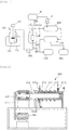
- the purification apparatus shown in FIGS. 1, 2 and 3 is a purification apparatus including a reactor.
- the apparatus includes a solution storage tank 100, an ultrasonic diffuser 200, an air compressor 300, a filter cartridge 400, a temperature control device 500, a continuous reactor 600, an organic material separator 700, an organic material storage tank 800, and an analyzer and compensator module 900.
- the solution storage tank 100 serves to store a solution containing an organic material (OLED) dissolved in an organic solvent.
- the concentration of the solution containing the organic material is preferably 100 g/L or less.
- the organic material refers to any kind of material disposed between positive and negative electrodes of an organic light-emitting device.
- the organic material or the organic metal material used for organic field-effect light-emitting device may include light-emitting host materials, dopant materials, hole injection-transfer materials, electron injection-transfer materials, hole/electron suppressing layer materials, etc.
- the solution storage tank 100 may have a heating jacket 110 provided outside and filled with a thermal fluid so that the heating jacket 110 can heat the solution of the solution storage tank 100 up to 350 oC at maximum to dissolve the organic material in the organic solvent.
- the solution storage tank 100 may further include an agitator 120 for uniformly mixing the organic solvent and the organic material together.
- the ultrasonic diffuser 200 is a device provided in the solution storage tank 100 to apply ultrasonic wave to the organic material and grind/reduce the organic material into nanoparticles.
- the organic material is not easily dissolved just by heating and required to be forcedly ground to enhance the dissolution efficiency.
- the ultrasonic diffuser has an oscillator, also called “generator”, that changes the voltage having a frequency of 50 to 60 Hz into a high-frequency electric energy, and the high-frequency electric energy is converted into mechanical vibrations by piezoelectric ceramics in the converter, which is called “inverse piezoelectric effect”.
- the vertical vibrations caused by the inverse piezoelectric effect are transferred to the liquid sample.
- the liquid sample is susceptible to expansion (negative pressure) and contraction (positive pressure) due to at least 20,000 vibrations per second and the constant amplitude of the probe (or tip) at which the ultrasonic vertical vibrations arrive in the liquid sample. Minute bubbles formed during this process break while the positive pressure is amplified. This phenomenon is called “cavitation", during which high-temperature and high-pressure instantaneous impulses having the pressure of about 1,000 bar and the instantaneous temperature of about 5,000 K generate and function as a source of very high energy to grind the organic material into particles.
- the air compressor 300 serves to suction the solution in the solution storage tank 100 and transfer it to the next position, filter cartridge 400. During the transfer of the hot solution, the temperature of the solution lowers to precipitate the solution into crystals. In order to prevent this happening, it is necessary to transfer the solution under reduced pressure. For this purpose, an air compressor is used.
- the filter cartridge 400 consists of a filter case 410 and a filler 420 filled in the filter case 410.
- the filler may include at least one selected from the group consisting of metal oxide, active alumina, silica, titanium oxide, and natural stone, such as active carbon, bentonite, acid clay, and diatomite, which are used alone or in combination of at least two.
- the temperature control device 500 is to raise the temperature of the filter cartridge 400 and prevent precipitation of crystals from the solution.
- the temperature control device 500 includes a casing 510 in which the filter cartridge 400 is mounted, a thermal fluid 520 filled in the casing 510, and a heater 530 for heating the thermal fluid 520.
- the continuous reactor 600 receives the solution passing through the filter cartridge 400 and an anti-solvent stored in an anti-solvent storage tank 10 by a pump p and agitates the solution and the anti-solvent to produce a reactant having uniform particles.
- the continuous reactor 600 includes a cylinder 610, a thermal fluid chamber 620, a partition panel 630, a temperature control member 640, an agitating body 650, an agitating motor 660, a belt pulley 670, and a belt 671.
- the cylinder 610 of the continuous reactor 600 has a reaction chamber 611 provided inside to receive the filtered solution and the anti-solvent.
- An anti-solvent inlet port 611a is provided on the one top side of the cylinder 610 to feed the anti-solvent into the reaction chamber 611, and a solution inlet port 611b is provided on the one bottom side of the cylinder 610 to feed the solution of the organic material.
- Reference number 611c denotes an outlet port through which the reactant after completion of the reaction is discharged.
- the thermal fluid chamber 620 is provided in the shape of a ring on the outer side of the reaction chamber 611 and filled with a thermal fluid for regulating the temperature of the solution and the anti-solvent in the reaction chamber.
- the thermal fluid chamber 620 is divided into a plurality of thermal fluid chambers by the partition panel 630, which consists of an insulating material to prevent a heat exchange of the thermal fluids filled in the plural thermal fluid chambers 620.
- heating the thermal fluid in each of the plural thermal fluid chambers 620 partitioned by the partition panel 630 at a different temperature creates a temperature gradient to the solution passing through the reaction chamber 611.
- the temperature gradient may vary depending on the temperature range of the thermal fluid.
- each thermal fluid chamber 620 may further include a temperature sensor 621 for sensing the temperature of the thermal fluid in each thermal fluid chamber and sending temperature data to the analyzer and compensator module 900.
- the temperature control member 640 serves to control the temperature of the thermal fluid.
- a circulator or a heater may be used as the temperature control member 640.
- the agitating body 650 is of a rod shape and provided to be rotatable in the cylinder 610.
- the agitating body 650 serves to agitate the solution and the anti-solvent in the cylinder 610.
- the mixing of fluids in the direction of the agitating body 650 decreases and the radial mixing of fluids increases.
- the flow of fluids in the direction of the agitating body 650 exists, mixing of fluids in the cells occurs, and the fluids close to the agitating body 650 is fixed by the centrifugal force and tends to move in the direction of the inner wall of the cylinder 100.
- An unsteady flow form a pair of rings rotating in the opposite direction to each other along the direction of the agitating body 650, that is, Taylor vortex flows, which change the rotational speed of the agitating body 650 to readily cause turbulent flows and use the fluid stability.
- the agitating motor 660 is arranged in the bottom portion of the cylinder 610 to provide a rotation power for the agitating body 650.
- the agitating motor 660 uses a speed-variable agitating motor capable of regulating the rotational speed in the range of 10 to 2,000 rpm by way of a DC voltage regulator (not shown). In this manner, the rotational speed of the agitating body 650 can be changed in the above-defined range (10 to 2,000 rpm), which leads to creation of turbulence in the solution.
- the agitating motor 660 and the agitating body 650 are indirectly connected to each other via the belt pulley 670 and the belt 671. As the high internal temperature of the cylinder 610 is transferred to the agitating body 650, the agitating body 650 is maintained at high temperature. A direct transfer of the high heat to the agitating motor 660 can shorten the lifespan of the agitating motor 660. It is therefore possible to prevent a heat transfer by providing an indirect connection between the agitating body 650 and the agitating motor 660 via the belt 671 as described above.
- the connection via the belt 671 is given as an example in the above description, it is not intended to limit the present invention and, of course, a connection via a chain or a gear is also available.
- the walls of the reaction chamber 611 and the thermal fluid chamber 620 may be coated with Teflon or made of hastelloy-C in order to provide corrosion resistance.
- Hastelloy-C which is a HCl-resistant alloy with high corrosion resistance, may solve the problem in regards to corrosion resistance when used for such a portion as the cylinder 610 of the present invention that frequently gets in contact with the chemical solutions.
- the organic material separator 700 is connected to the outlet port 611c of the continuous reactor 600 to divide the slurry-like reactant discharged from the continuous reactor 600 into a solid organic material and a filtrate.
- the organic material storage tank 800 serves to store the solid organic material isolated by the organic material separator 700.
- the analyzer and compensator module 900 collects a liquid isolated by the organic material separator 700, analyzes the liquid to determine whether it is in the normal state or not, and performs compensation to an optimal condition according to the analyzed data.
- the compensation function may be controlled by a computer.
- an apparatus that includes a dehydrator and a dryer for purification of tryptophan in addition to the above-specified components, such as the continuous reactor, the storage tank, the agitator, the diffuser, and the heating jacket.
- the purification apparatus for purifying tryptophan includes, as shown in FIG. 4 , a solid filter 10, a storage tank 20, a heating jacket 30, an air compressor 40, a continuous reactor 50, a dehydrator 60, and a dryer 70.
- the solid filter 10 filters out the solid matter from a tryptophan solution and allows the solution to pass through.
- the solid filter 10 has a mesh (or pore) size of 0.1 ⁇ m or greater, preferably 0.1 to 0.5 ⁇ m so as to filter out all the solids 0.5 ⁇ m or larger in size from the tryptophan solution and allow only the minute solids having a size of less than 0.5 ⁇ m to pass through. Consequently, the first purification step is performed.
- the storage tank 20 has a function of storing the tryptophan solution passed through the solid filter 10. At this, the storage tank 20 includes a temperature sensor 21 for sensing the temperature of the tryptophan solution stored in the storage tank 20 in real time.
- the heating jacket 30 is provided outside the storage tank 20 to control the internal temperature of the storage tank 20.
- the heating jacket 30, which is filled with a thermal fluid, is disposed to immerse a part of the storage tank 20 and heat the thermal fluid by a heat source so that the tryptophan solution in the storage tank 20 can be controlled to have an appropriate temperature.
- the air compressor 40 has a function of suctioning the tryptophan solution in the storage tank 20 and transferring it to the next position.
- the continuous reactor 50 receives the tryptophan solution transferred by the air compressor 40 and sulfuric acid transferred through a separate passage and agitates the solutions to continuously produce a reactant.
- the continuous reactor is as defined above and its construction will not be separately described any more.
- the dehydrator 60 is connected to the outlet port of the continuous reactor 50 to separate a filtrate from the slurry-like reactant discharged from the continuous reactor 50.
- a centrifugal separator may be used for the dehydrator 60.
- the tryptophan purification method disclosed in the present invention has the following procedures (Refer to FIG. 5 ).
- the solid removal step is passing the tryptophan solution through the solid filter before storing it in the storage tank to eliminate solids of a predetermined size or greater.
- the filter used in the solid removal step preferably has a mesh (or pore) size of 0.1 to 0.5 ⁇ m.
- the dissolved solids 0.5 ⁇ m or larger in size are filtered out from the tryptophan solution, so the tryptophan solution contains minute solids having a size of less than 0.5 ⁇ m.
- Second step pH adjusting step S20.
- the pH adjusting step S20 is adding NaOH (caustic soda) into the storage tank to adjust the pH value of the tryptophan solution.
- the pH value of the tryptophan solution is preferably in the range of 11 to 3.
- the temperature control step S30 is providing the heating jacket outside the storage tank to maintain the tryptophan solution in the solution storage tank at a constant temperature.
- the density enhancing step S40 is adding a polymer material to the tryptophan solution in the storage tank to enhance the particle density of the tryptophan solution. This step involves using the continuous reactor.
- the polymer material may be any one selected from polyvinyl alcohol (PVA), Carrageenan, alginic acid, HPC, or gelatin.
- PVA polyvinyl alcohol
- Carrageenan Carrageenan
- alginic acid HPC
- gelatin gelatin
- FIG. 4 for example, large crystals are observed in the tryptophan solution with an elapse of time in either case of using PVA or gelatin.
- the tryptophan crystals using the polymer material have the higher growth rate than those not using the polymer material.
- the tryptophan crystals grow larger with an increase in the content of the acid solution (especially, sulfuric acid), which will be described in the sixth step.
- the particles of the tryptophan solution grow to a size of about 300 ⁇ m or greater.
- the use of sonication leads to the reduced strength of the particles to make the particles fragile.
- the strength of the particles can be enhanced when the polymer material is controlled to have a lower molecular weight.
- the feeding step S50 is feeding the tryptophan solution of the storage tank into the continuous reactor.
- the feeding process may be carried out automatically by way of an air compressor or the like. The construction of the continuous reactor will be described later.
- the crystal precipitation step S60 is the process of adding an acid solution (especially, sulfuric acid) to the tryptophan solution fed into the continuous reactor to neutralize the pH value of the tryptophan solution and precipitate particulate crystals.
- an acid solution especially, sulfuric acid
- the tryptophan solution is an amphoteric substance very soluble in an acid solution or an alkaline solution.
- the opposite solution i.e., an alkaline solution or an acid solution
- an acid solution is added after the tryptophan solution is dissolved in a NaOH solution, to neutralize the pH value of the tryptophan solution and precipitate crystals.
- the solid-liquid separation step S70 is a process of dehydrating the precipitated particulate crystals of the continuous reactor with the dehydrator to perform a solid-liquid separation.
- the solid-liquid separation step S70 is adding the tryptophan crystals obtained with high water content into a centrifugal dehydrator to lower the water content to 60 % or less.
- dehydration is performed for a predetermined time, and the dehydrated sludge-like tryptophan crystals are collected and measured in regards to the water content with a water content measurer. According to the measurement results, there is a need for a process to increase or decrease the dehydration time.
- the rotational speed of the dehydrator is 5,000 to 12,000 rpm and the dehydration time is 50 to 60 minutes. If the dehydrator is rotated at a low speed less than 500 rpm, the dehydration time becomes too long. If the rotational speed of the dehydrator is higher than 12,000 rpm, there is no significant difference in the dehydration rate from the case of rotating the dehydrator at the lower rotational speed, thus ending up with deteriorated dehydration efficiency.
- the tryptophan sludge cake which still has a high water content even after the completion of dehydration, needs to be dried with hot air into powder having a reduced water content of 10 % or less.
- Such a pulverizing process leads to a yield of tryptophan with high purity.
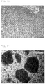
- FIGS. 6, 7 and 8 are microscopic images of the cases 1, 2 and 3 of Table 1, respectively.
- the recovery rate is about 95 % or greater without a significant change depending on the reaction time, which shows that the tryptophan is precipitated in a short time.
- the particle size increases with a decrease in the tryptophan concentration.
- the purity is about 99 % or greater in all conditions.
- the recovery rate is about 75 % in all conditions. Reducing the dissolved tryptophan concentration is one of the methods to inhibit nucleation, and this method proves to be appropriate. It is considered that as the nucleation occurs less, tryptophan sticks to the nuclei to grow into crystals.
- the particle size increases with the reduced agitation rate.
- This material is a plate-shaped substance with the weak bonding strength of particles.
- the analytic results show that the crystals form to be easily broken as the plate is only 1 ⁇ m or less in height.
Landscapes
- Chemical & Material Sciences (AREA)
- Organic Chemistry (AREA)
- Chemical Kinetics & Catalysis (AREA)
- Crystallography & Structural Chemistry (AREA)
- Health & Medical Sciences (AREA)
- General Health & Medical Sciences (AREA)
- Toxicology (AREA)
- Indole Compounds (AREA)
- Physical Or Chemical Processes And Apparatus (AREA)
Description
- The present invention relates to a purification apparatus including continuous reactors and, more particularly to, a purification apparatus that involves diffusing/agitating a solution stored in a solution storage tank with the ultrasonic wave, transferring the solution to a reactor through an air compressor and then mixing the solution in the reactor with a solvent fed through another passage to produce a reactant, and a purification method using the purification apparatus.
- Generally, many materials need to be purified. Purification is also required to organic materials and essential amino acids used for feedstuff additives, medicines, health foods, etc. For example, organic materials used for organic light-emitting device are obtained by isolating a pure target component from the conventional synthetic substance for the use purpose in thin film deposition. With enhanced purification techniques of the organic materials, the organic light-emitting devices are allowed to improve the light-emitting efficiency and extend the light-emission life span.
- For the production of organic materials on a large scale, it is essential to use the purification techniques for organic materials with reduced process time and enhanced purification efficiency.
- Tryptophan is one of essential amino acids. The conventional purification techniques for tryptophan are disclosed in Japanese Patent Publication Nos.
126070/1986 39857/1984 126070/1983 - However, the method of using an ultrafiltration membrane according to the technique of Japanese Patent Publication No.
895/1983 - Further, the method specified in Japanese Patent Publication No.
39857/1984 - Furthermore, the method disclosed in Japanese Patent Publication No.
126070/1986 - Document
US 3,892,539 discloses a purification apparatus and method for production of crystals in fluidized bed crystallizers. - For solving the problem with the prior art, it is an object of the present invention to provide an ultrahigh purification apparatus including a continuous reactor that has a construction capable of producing an organic material for organic light-emitting device with ultrahigh purity of 99.9 % or greater, which purification apparatus involves diffusing/agitating a solution with ultrasonic wave, transferring the solution to the reactor through an air compressor and mixing the solution with a solvent added through another passage in the reactor to produce a reactant.
- It is another object of the present invention to provide a tryptophan purification apparatus that adopts a method of dissolving tryptophan in an acid solution or an alkaline solution and then adding the opposite solution (i.e., an alkaline solution or an acid solution) to neutralize the pH value to cause precipitation and uses a continuous reactor to continuously yield the product, increase the production rate three times as fast as the existing methods, enhance recovery rate and purity and increase the density of particles by using a polymer material as an additive, resulting in the higher strength of the product that makes the product not easily broken.
- In accordance with one embodiment of the present invention, the present invention provides a purification apparatus according to claim 1 and a tryptophan purification method according to claim 9.
- According to the construction of the present invention, it is possible to produce an organic material used for organic light-emitting device with ultrahigh purity on a large scale. Particularly, the crystallization method according to the present invention can obtain an organic material having an ultrahigh purity of 99.9 % or greater.
- The organic field-effect light-emitting device made using the organic material can benefit from the use of the organic material of higher purity in terms of reduced dark spot growth, improved electric/optical characteristics of the device and extended lifespan of the device.
- Further, relative to the conventional methods, the present invention using a continuous reactor can enhance in the recovery rate of tryptophan by about 10 %, enable continuous production with enhanced production rate three times or greater and increase the purity to 99.9 % or higher.
- Furthermore, the present invention using a polymer material as an additive can enhance the density of particles and thus make the particles not easily broken.
-
-
FIG. 1 is an illustration showing the construction of an ultrahigh purification apparatus according to the present invention. -
FIG. 2 is a detailed illustration showing the construction of a continuous reactor adopted in the purification apparatus according to the present invention. -
FIG. 3 is an illustration showing the construction of a cylinder of the continuous reactor in the purification apparatus according to the present invention. -
FIG. 4 is an illustration showing the construction of a tryptophan purification apparatus as another embodiment of the purification apparatus according to the present invention. -
FIG. 5 is a flow chart showing a tryptophan purification method according to the present invention. -
FIGS. 6, 7 and8 show the change of crystals as a function of the addition rate of sulfuric acid in the tryptophan purification method according to the present invention. -
FIG. 9 is a particle size distribution graph in the tryptophan purification method according to the present invention. -
FIGS. 10 to 13 show images of the tryptophan crystal shape as a function of the reaction time (1 hour inFIG. 10 ,6 hours inFIG. 11 , 26 hours inFIG. 12 , and 52 hours inFIG. 13 ) in the tryptophan purification method according to the present invention. -
FIG. 14 is a graph showing the change of the particle size as a function of the dissolved tryptophan concentration in the tryptophan purification method according to the present invention. -
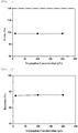
FIG. 15 is a graph showing the change of the purity as a function of the dissolved tryptophan concentration in the tryptophan purification method according to the present invention. -
FIG. 16 is a graph showing the change of the recovery rate as a function of the dissolved tryptophan concentration in the tryptophan purification method according to the present invention. -
FIGS. 17 and 18 are images showing the change of the particle shape as a function of the agitation rate in the tryptophan purification method according to the present invention. -
FIG. 19 is a graph showing the change of the particle size as a function of the agitation rate in the tryptophan purification method according to the present invention. - The present invention is a purification apparatus including a reactor that is composed of a solution storage tank, an ultrasonic diffuser, an agitator, a heating jacket, an air compressor, and a reactor, and further optionally includes a filter a separator or a dehydrator, a dryer, etc.
- The purification apparatus shown in
FIGS. 1, 2 and3 is a purification apparatus including a reactor. The apparatus includes asolution storage tank 100, anultrasonic diffuser 200, anair compressor 300, afilter cartridge 400, atemperature control device 500, acontinuous reactor 600, anorganic material separator 700, an organicmaterial storage tank 800, and an analyzer andcompensator module 900. - The
solution storage tank 100 serves to store a solution containing an organic material (OLED) dissolved in an organic solvent. The concentration of the solution containing the organic material is preferably 100 g/L or less. When the concentration of the solution containing the organic material is above the concentration range, the crystallization reaction is retarded or the desired purity is hard to achieve. In this regard, the organic material refers to any kind of material disposed between positive and negative electrodes of an organic light-emitting device. For example, the organic material or the organic metal material used for organic field-effect light-emitting device may include light-emitting host materials, dopant materials, hole injection-transfer materials, electron injection-transfer materials, hole/electron suppressing layer materials, etc. - The
solution storage tank 100 may have aheating jacket 110 provided outside and filled with a thermal fluid so that theheating jacket 110 can heat the solution of thesolution storage tank 100 up to 350 ºC at maximum to dissolve the organic material in the organic solvent. - Besides, the
solution storage tank 100 may further include anagitator 120 for uniformly mixing the organic solvent and the organic material together. - The
ultrasonic diffuser 200 is a device provided in thesolution storage tank 100 to apply ultrasonic wave to the organic material and grind/reduce the organic material into nanoparticles. The organic material is not easily dissolved just by heating and required to be forcedly ground to enhance the dissolution efficiency. - For reference, the ultrasonic diffuser has an oscillator, also called "generator", that changes the voltage having a frequency of 50 to 60 Hz into a high-frequency electric energy, and the high-frequency electric energy is converted into mechanical vibrations by piezoelectric ceramics in the converter, which is called "inverse piezoelectric effect". The vertical vibrations caused by the inverse piezoelectric effect are transferred to the liquid sample. The liquid sample is susceptible to expansion (negative pressure) and contraction (positive pressure) due to at least 20,000 vibrations per second and the constant amplitude of the probe (or tip) at which the ultrasonic vertical vibrations arrive in the liquid sample. Minute bubbles formed during this process break while the positive pressure is amplified. This phenomenon is called "cavitation", during which high-temperature and high-pressure instantaneous impulses having the pressure of about 1,000 bar and the instantaneous temperature of about 5,000 K generate and function as a source of very high energy to grind the organic material into particles.
- The
air compressor 300 serves to suction the solution in thesolution storage tank 100 and transfer it to the next position,filter cartridge 400. During the transfer of the hot solution, the temperature of the solution lowers to precipitate the solution into crystals. In order to prevent this happening, it is necessary to transfer the solution under reduced pressure. For this purpose, an air compressor is used. - The
filter cartridge 400 consists of afilter case 410 and afiller 420 filled in thefilter case 410. The filler may include at least one selected from the group consisting of metal oxide, active alumina, silica, titanium oxide, and natural stone, such as active carbon, bentonite, acid clay, and diatomite, which are used alone or in combination of at least two. - The
temperature control device 500 is to raise the temperature of thefilter cartridge 400 and prevent precipitation of crystals from the solution. Thetemperature control device 500 includes acasing 510 in which thefilter cartridge 400 is mounted, athermal fluid 520 filled in thecasing 510, and aheater 530 for heating thethermal fluid 520. - The
continuous reactor 600 receives the solution passing through thefilter cartridge 400 and an anti-solvent stored in ananti-solvent storage tank 10 by a pump p and agitates the solution and the anti-solvent to produce a reactant having uniform particles. Thecontinuous reactor 600 includes acylinder 610, athermal fluid chamber 620, a partition panel 630, a temperature control member 640, an agitatingbody 650, an agitatingmotor 660, a belt pulley 670, and abelt 671. - The
cylinder 610 of thecontinuous reactor 600 has areaction chamber 611 provided inside to receive the filtered solution and the anti-solvent. Ananti-solvent inlet port 611a is provided on the one top side of thecylinder 610 to feed the anti-solvent into thereaction chamber 611, and asolution inlet port 611b is provided on the one bottom side of thecylinder 610 to feed the solution of the organic material.Reference number 611c (unexplained) denotes an outlet port through which the reactant after completion of the reaction is discharged. - The
thermal fluid chamber 620 is provided in the shape of a ring on the outer side of thereaction chamber 611 and filled with a thermal fluid for regulating the temperature of the solution and the anti-solvent in the reaction chamber. - In this regard, the
thermal fluid chamber 620 is divided into a plurality of thermal fluid chambers by the partition panel 630, which consists of an insulating material to prevent a heat exchange of the thermal fluids filled in the plural thermalfluid chambers 620. - Accordingly, heating the thermal fluid in each of the plural thermal
fluid chambers 620 partitioned by the partition panel 630 at a different temperature creates a temperature gradient to the solution passing through thereaction chamber 611. The temperature gradient may vary depending on the temperature range of the thermal fluid. - Further, each
thermal fluid chamber 620 may further include atemperature sensor 621 for sensing the temperature of the thermal fluid in each thermal fluid chamber and sending temperature data to the analyzer andcompensator module 900. - The temperature control member 640 serves to control the temperature of the thermal fluid. For example, a circulator or a heater may be used as the temperature control member 640.
- The agitating
body 650 is of a rod shape and provided to be rotatable in thecylinder 610. The agitatingbody 650 serves to agitate the solution and the anti-solvent in thecylinder 610. As the agitatingbody 650 rotates, the mixing of fluids in the direction of the agitatingbody 650 decreases and the radial mixing of fluids increases. When the flow of fluids in the direction of the agitatingbody 650 exists, mixing of fluids in the cells occurs, and the fluids close to the agitatingbody 650 is fixed by the centrifugal force and tends to move in the direction of the inner wall of thecylinder 100. An unsteady flow form a pair of rings rotating in the opposite direction to each other along the direction of the agitatingbody 650, that is, Taylor vortex flows, which change the rotational speed of the agitatingbody 650 to readily cause turbulent flows and use the fluid stability. - The agitating
motor 660 is arranged in the bottom portion of thecylinder 610 to provide a rotation power for the agitatingbody 650. The agitatingmotor 660 uses a speed-variable agitating motor capable of regulating the rotational speed in the range of 10 to 2,000 rpm by way of a DC voltage regulator (not shown). In this manner, the rotational speed of the agitatingbody 650 can be changed in the above-defined range (10 to 2,000 rpm), which leads to creation of turbulence in the solution. - The agitating
motor 660 and the agitatingbody 650 are indirectly connected to each other via the belt pulley 670 and thebelt 671. As the high internal temperature of thecylinder 610 is transferred to the agitatingbody 650, the agitatingbody 650 is maintained at high temperature. A direct transfer of the high heat to the agitatingmotor 660 can shorten the lifespan of the agitatingmotor 660. It is therefore possible to prevent a heat transfer by providing an indirect connection between the agitatingbody 650 and the agitatingmotor 660 via thebelt 671 as described above. Although the connection via thebelt 671 is given as an example in the above description, it is not intended to limit the present invention and, of course, a connection via a chain or a gear is also available. - On the other hand, the walls of the
reaction chamber 611 and thethermal fluid chamber 620 may be coated with Teflon or made of hastelloy-C in order to provide corrosion resistance. Hastelloy-C, which is a HCl-resistant alloy with high corrosion resistance, may solve the problem in regards to corrosion resistance when used for such a portion as thecylinder 610 of the present invention that frequently gets in contact with the chemical solutions. - The
organic material separator 700 is connected to theoutlet port 611c of thecontinuous reactor 600 to divide the slurry-like reactant discharged from thecontinuous reactor 600 into a solid organic material and a filtrate. - The organic
material storage tank 800 serves to store the solid organic material isolated by theorganic material separator 700. - The analyzer and
compensator module 900 collects a liquid isolated by theorganic material separator 700, analyzes the liquid to determine whether it is in the normal state or not, and performs compensation to an optimal condition according to the analyzed data. The compensation function may be controlled by a computer. - Hereinafter, a description will be given as to an apparatus that includes a dehydrator and a dryer for purification of tryptophan in addition to the above-specified components, such as the continuous reactor, the storage tank, the agitator, the diffuser, and the heating jacket.
- The purification apparatus for purifying tryptophan includes, as shown in
FIG. 4 , asolid filter 10, astorage tank 20, aheating jacket 30, anair compressor 40, acontinuous reactor 50, adehydrator 60, and adryer 70. - The
solid filter 10 filters out the solid matter from a tryptophan solution and allows the solution to pass through. In this regard, thesolid filter 10 has a mesh (or pore) size of 0.1 µm or greater, preferably 0.1 to 0.5 µm so as to filter out all the solids 0.5 µm or larger in size from the tryptophan solution and allow only the minute solids having a size of less than 0.5 µm to pass through. Consequently, the first purification step is performed. Thestorage tank 20 has a function of storing the tryptophan solution passed through thesolid filter 10. At this, thestorage tank 20 includes atemperature sensor 21 for sensing the temperature of the tryptophan solution stored in thestorage tank 20 in real time. - The
heating jacket 30 is provided outside thestorage tank 20 to control the internal temperature of thestorage tank 20. Theheating jacket 30, which is filled with a thermal fluid, is disposed to immerse a part of thestorage tank 20 and heat the thermal fluid by a heat source so that the tryptophan solution in thestorage tank 20 can be controlled to have an appropriate temperature. - The
air compressor 40 has a function of suctioning the tryptophan solution in thestorage tank 20 and transferring it to the next position. - The
continuous reactor 50 receives the tryptophan solution transferred by theair compressor 40 and sulfuric acid transferred through a separate passage and agitates the solutions to continuously produce a reactant. - The continuous reactor is as defined above and its construction will not be separately described any more.
- The
dehydrator 60 is connected to the outlet port of thecontinuous reactor 50 to separate a filtrate from the slurry-like reactant discharged from thecontinuous reactor 50. A centrifugal separator may be used for thedehydrator 60. - The tryptophan purification method disclosed in the present invention has the following procedures (Refer to
FIG. 5 ). - First step: Solid removal step S10.
- The solid removal step is passing the tryptophan solution through the solid filter before storing it in the storage tank to eliminate solids of a predetermined size or greater. In this regard, the filter used in the solid removal step preferably has a mesh (or pore) size of 0.1 to 0.5 µm. Thus, the dissolved solids 0.5 µm or larger in size are filtered out from the tryptophan solution, so the tryptophan solution contains minute solids having a size of less than 0.5 µm.
- Second step: pH adjusting step S20.
- The pH adjusting step S20 is adding NaOH (caustic soda) into the storage tank to adjust the pH value of the tryptophan solution. In this regard, the pH value of the tryptophan solution is preferably in the range of 11 to 3.
- Third step: Temperature control step S30.
- The temperature control step S30 is providing the heating jacket outside the storage tank to maintain the tryptophan solution in the solution storage tank at a constant temperature.
- Fourth step: Density enhancing step S40.
- The density enhancing step S40 is adding a polymer material to the tryptophan solution in the storage tank to enhance the particle density of the tryptophan solution. This step involves using the continuous reactor.
- In this regard, the polymer material may be any one selected from polyvinyl alcohol (PVA), Carrageenan, alginic acid, HPC, or gelatin. As can be seen from
FIG. 4 , for example, large crystals are observed in the tryptophan solution with an elapse of time in either case of using PVA or gelatin. The tryptophan crystals using the polymer material have the higher growth rate than those not using the polymer material. The tryptophan crystals grow larger with an increase in the content of the acid solution (especially, sulfuric acid), which will be described in the sixth step. - Due to the addition of the polymer material, the particles of the tryptophan solution grow to a size of about 300 µm or greater. In this case, the use of sonication leads to the reduced strength of the particles to make the particles fragile. But, the strength of the particles can be enhanced when the polymer material is controlled to have a lower molecular weight.
- Fifth step: Feeding step S50.
- The feeding step S50 is feeding the tryptophan solution of the storage tank into the continuous reactor. The feeding process may be carried out automatically by way of an air compressor or the like. The construction of the continuous reactor will be described later.
- Sixth step: Crystal precipitation step S60.
- The crystal precipitation step S60 is the process of adding an acid solution (especially, sulfuric acid) to the tryptophan solution fed into the continuous reactor to neutralize the pH value of the tryptophan solution and precipitate particulate crystals.
- In other words, the tryptophan solution is an amphoteric substance very soluble in an acid solution or an alkaline solution. After dissolving the tryptophan solution in the acid solution or the alkaline solution, the opposite solution (i.e., an alkaline solution or an acid solution) is added (for example, an acid solution is added after the tryptophan solution is dissolved in a NaOH solution), to neutralize the pH value of the tryptophan solution and precipitate crystals.
- Seventh step: Solid-liquid separation step S70.
- The solid-liquid separation step S70 is a process of dehydrating the precipitated particulate crystals of the continuous reactor with the dehydrator to perform a solid-liquid separation.
- In other words, the solid-liquid separation step S70 is adding the tryptophan crystals obtained with high water content into a centrifugal dehydrator to lower the water content to 60 % or less. In order to calculate the proper dehydration time, dehydration is performed for a predetermined time, and the dehydrated sludge-like tryptophan crystals are collected and measured in regards to the water content with a water content measurer. According to the measurement results, there is a need for a process to increase or decrease the dehydration time.
- In the preferred embodiment as achieved in the above procedures, the rotational speed of the dehydrator is 5,000 to 12,000 rpm and the dehydration time is 50 to 60 minutes. If the dehydrator is rotated at a low speed less than 500 rpm, the dehydration time becomes too long. If the rotational speed of the dehydrator is higher than 12,000 rpm, there is no significant difference in the dehydration rate from the case of rotating the dehydrator at the lower rotational speed, thus ending up with deteriorated dehydration efficiency.
- Eighth step: Drying step S80.
- In the drying step S80, the tryptophan sludge cake, which still has a high water content even after the completion of dehydration, needs to be dried with hot air into powder having a reduced water content of 10 % or less. In this regard, it is possible to add a process of washing the sludge cake and eliminating the washing water using a centrifugal separator, before drying the sludge cake with hot air. Such a pulverizing process leads to a yield of tryptophan with high purity.
-
- Tryptophan concentration: 200 g/L
- NaOH concentration: 5 mol/L
- Initial pH: 14
- H2SO4 concentration: 30 %
- Agitation rate: 300 rpm
- Reaction temperature: 25 °C
- H2SO4 feeding rate: 0.5 mL/min, 2 mL/min, all at once.
- It can be seen that the particle size of crystals decreases with an increase in the H2SO4 feeding rate. It is necessary to shorten the reaction time, because the particle size decreases with an increase in the reaction time.
[Table 1] Particle size Cloud point Final pH PSA (µm) Microscopy (µm) Time pH 1 48.64 40 - 45 Immediate - 7.6 2 31 20 - 30 37 min 9.26 7.7 3 12.49 10 - 20 110 min 10.3 7.6 - For reference,
FIGS. 6, 7 and8 are microscopic images of thecases 1, 2 and 3 of Table 1, respectively. -
- Tryptophan concentration: 100 g/L
- NaOH concentration: 5 mol/L
- Initial pH: 14
- H2SO4 concentration: 30 %
- Agitation rate: 300 rpm
- Reaction temperature: 25 °C
- H2SO4 feeding amount and rate: 100 mL & 16.7 mL/min
- Other conditions: neutralize until
pH 7 and then agitate for long time - Although this experiment shows that tryptophan crystals with large particle size can be produced only when the reaction time is short, a short agitation time leads to production of small crystals having weak bonds and thus being easily broken. As shown in
FIGS. 9 and10 to 13 , it is a tendency that the longer reaction time results in the lower yield of medium-sized crystals but the higher yield of large-sized crystals. However, the particle size distribution is uniform when the reaction time is about 18 times or less. - The recovery rate is about 95 % or greater without a significant change depending on the reaction time, which shows that the tryptophan is precipitated in a short time.
-
- NaOH concentration: 5 mol/L
- Tryptophan concentration: 10, 100, 200 g/L
- H2SO4 concentration: 30 %
- Agitation rate: 100, 300 rpm
- Reaction temperature: 25 °C
- pH: 7
- Reaction time: 6 hrs
- As shown in
FIG. 14 , the particle size increases with a decrease in the tryptophan concentration. As shown inFIG. 15 , the purity is about 99 % or greater in all conditions. As shown inFIG. 16 , the recovery rate is about 75 % in all conditions. Reducing the dissolved tryptophan concentration is one of the methods to inhibit nucleation, and this method proves to be appropriate. It is considered that as the nucleation occurs less, tryptophan sticks to the nuclei to grow into crystals. -
- NaOH concentration: 5 mol/L
- Tryptophan concentration: 10 g/L
- H2SO4 concentration: 30 %
- Agitation rate: 100, 300 rpm
- Reaction temperature: 25 °C
- pH: 7
- Reaction time: 6 hrs
- As shown in
FIGS. 17, 18 and19 , the particle size increases with the reduced agitation rate. This material is a plate-shaped substance with the weak bonding strength of particles. The analytic results show that the crystals form to be easily broken as the plate is only 1 µm or less in height.
Claims (9)
- A purification apparatus comprising a continuous reactor, the purification apparatus comprising:- a solution storage tank (100) for storing a solution;- an sonicator (200) for dispersing the particles contained in the solution of the solution storage tank (100) with ultrasonic wave;- an agitator (120) for agitating the solution stored in the solution storage tank;- a heating jacket provided outside the solution storage tank to control the internal temperature of the solution storage tank;- an air compressor (300); and- a reactor comprising a reaction chamber (611) comprising an inlet (611b) through which the solution from the tank is fed in, and an inlet (611a) through which an antisolvent is fed in, thus mixing the solution and the antisolvent, and an outlet (611c), and comprising an agitator body (650) for stirring the mixture at high speed to continuously produce a reactant having uniform particles;characterized in that the solution is transferred from the tank to the inlet of the reaction chamber under reduced pressure using the air compressor (300).
- The apparatus according to claim 1, further comprising:- a filter cartridge for filtering out minute impurities contained in the solution before feeding it under reduced pressure into the reaction chamber;- a temperature control device comprising a casing receiving the filter cartridge, a thermal fluid filled in the casing, and a heater for heating the thermal fluid;- an organic material separator connected to the outlet of the reaction chamber to divide the slurry-like reactant discharged from the continuous reactor into an organic material and a filtrate;- an organic material storage tank for storing the organic material in the solid state isolated by the organic material separator; and- an analyzer and compensator module for collecting a liquid isolated by the organic material separator, analyzing the liquid to determine whether the liquid is in the normal state or not, and performing compensation to an optimal condition according to the analyzed data.
- The apparatus according to claim 2, wherein the filter cartridge comprises a filter case and a filler filled in the filter case, the filler comprising at least one selected from the group consisting of metal oxide, active alumina, silica, titanium oxide, active carbon, bentonite, acid clay, and diatomite.
- The apparatus accoding to claim 2, wherein the organic material separator is a centrifugal separator or a dehydrator.
- The apparatus accoding to claim 1, wherein the continuous reactor comprises:- a cylinder encasing the reaction chamber, the anti-solvent inlet port being provided on the top side thereof, and the solution inlet being provided on the bottom side thereof to feed the solution of the organic material;- a thermal fluid chamber provided in the shape of a ring on the outer side of the reaction chamber and filled with a thermal fluid for regulating the temperature of the solution and the anti-solvent in the reaction chamber;- a partition panel provided to divide the space of the thermal fluid chamber into a plurality of thermal fluid chambers and formed of an insulating material to prevent a heat exchange of the thermal fluids filled in the plural thermal fluid chambers;- a temperature control member for controlling the temperature of the thermal fluid filled in each thermal fluid chamber isolated by the partition panel;- an agitating body provided to be rotatable in the cylinder and agitate the solution and the anti-solvent in the cylinder;- an agitating motor arranged in the bottom portion of the cylinder; and- a belt pulley and a belt connecting the axis of the agitating motor to the one end of the agitating body to transfer the driving force of the agitating motor to the agitating body.
- The apparatus according to cliam 5, wherein the continuous reactor further comprises a temperature sensor for sensing the temperature of the thermal fluid in each thermal fluid chamber and sending temperature data to the analyzer and compensator module.
- The apparatus according to claim 5, wherein the reaction chamber and the thermal fluid chamber have walls coated with Teflon or formed of hastelloy-C to provide corrosion resistance.
- The apparatus according to claim1, further comprising:- a solid filter for filtering out solid matter from the solution and separating the solution, stored in the solution storage tank after having passed through the solid filter;-- a dehydrator connected to the outlet of the reaction chamber, to separate a filtrate from the slurry-like reactant discharged from the continuous reactor; and- a dryer for drying a solid component separated from the dehydrator.
- A tryptophan purification method using the purification apparatus according to claim 8, the tryptophan purification method comprising:- a solid removal step (S10) of passing the tryptophan solution through the solid filter before storing in the solution storage tank to eliminate solid matter of a predetermined size or greater;- a pH adjusting step (S20) of adding NaOH into the solution storage tank to adjust the pH value of the tryptophan solution;- a temperature control step (S30) of providing the heating jacket outside the solution storage tank to maintain the temperature of the tryptophan solution in the solution storage tank at a constant level;- a density enhancing step (S40) of adding a polymer material to the tryptophan solution in the solution storage tank to enhance the particle density of the tryptophan solution;- a feeding step (S50) of feeding the tryptophan solution of the solution storage tank into the reaction chamber of the continuous reactor;- a crystal precipitation step (S60) of adding an acid solution to the tryptophan solution fed into the continuous reactor to neutralize the pH value of the tryptophan solution and precipitate particulate crystals;- a solid-liquid separation step (S70) of dehydrating the precipitated particulate crystals with the dehydrator to perform a solid-liquid separation; and- a drying step (S80) of hot-air drying the solid component;characterized in that the feeding step is performed under reduced pressure using an air compressor.
Applications Claiming Priority (3)
| Application Number | Priority Date | Filing Date | Title |
|---|---|---|---|
| KR1020120097027A KR101427324B1 (en) | 2012-09-03 | 2012-09-03 | Ultra-high purity purification device that includes a continuous reactor |
| KR1020120107996A KR101372811B1 (en) | 2012-09-27 | 2012-09-27 | Tryptophan purification devices and methods |
| PCT/KR2013/007885 WO2014035211A1 (en) | 2012-09-03 | 2013-09-02 | Refining device including continuous reactor and refining method using continuous reactor |
Publications (3)
| Publication Number | Publication Date |
|---|---|
| EP2893964A1 EP2893964A1 (en) | 2015-07-15 |
| EP2893964A4 EP2893964A4 (en) | 2016-05-25 |
| EP2893964B1 true EP2893964B1 (en) | 2019-11-27 |
Family
ID=50183933
Family Applications (1)
| Application Number | Title | Priority Date | Filing Date |
|---|---|---|---|
| EP13833620.1A Active EP2893964B1 (en) | 2012-09-03 | 2013-09-02 | Purification device including continuous reactor and purification method using continuous reactor |
Country Status (4)
| Country | Link |
|---|---|
| US (2) | US20150165340A1 (en) |
| EP (1) | EP2893964B1 (en) |
| JP (1) | JP6352919B2 (en) |
| WO (1) | WO2014035211A1 (en) |
Families Citing this family (9)
| Publication number | Priority date | Publication date | Assignee | Title |
|---|---|---|---|---|
| US20150165340A1 (en) * | 2012-09-03 | 2015-06-18 | Laminar Co., Ltd. | Purification System Comprising Continuous Reactor and Purification Method Using Continuous Reactor |
| US10201797B2 (en) * | 2012-11-27 | 2019-02-12 | Laminar Co., Ltd. | Reaction device for mixing and manufacturing method using the reaction device |
| KR101424610B1 (en) | 2013-06-14 | 2014-08-04 | (주) 라미나 | An Apparatus of Core-Shell Particles and Preparation Methods Using Thereof |
| CN106133940B (en) * | 2014-03-28 | 2018-07-20 | 显示器生产服务株式会社 | Organic material purification method and device using ionic liquid |
| CN105396530A (en) * | 2014-09-12 | 2016-03-16 | 天津法莫西医药科技有限公司 | Biochemical reaction apparatus for preparing biological preparations |
| WO2021012044A1 (en) | 2019-07-22 | 2021-01-28 | Canopy Growth Corporation | Continuous crystallization of cannabinoids in a stirred-tank reactor |
| CN113582913B (en) * | 2021-08-18 | 2023-01-03 | 河北广祥制药有限公司 | Method for continuously refining nifedipine |
| CN114797547B (en) * | 2022-06-07 | 2024-03-12 | 重庆新申新材料股份有限公司 | Liquid feeding device is used in production of high-purity strontium compound, barium compound solution |
| CN118698465B (en) * | 2024-08-28 | 2024-12-13 | 深圳信息职业技术学院 | Simple and efficient potassium ferrate integrated preparation device and method |
Family Cites Families (25)
| Publication number | Priority date | Publication date | Assignee | Title |
|---|---|---|---|---|
| US2725219A (en) * | 1953-02-16 | 1955-11-29 | Firth George | Reactor |
| US3004013A (en) * | 1954-04-28 | 1961-10-10 | Detrex Corp | Method for producing finely divided polyvinyl chloride |
| US3892539A (en) * | 1969-09-26 | 1975-07-01 | Merck & Co Inc | Process for production of crystals in fluidized bed crystallizers |
| JPS58895A (en) | 1981-06-26 | 1983-01-06 | Mitsui Toatsu Chem Inc | Preparation of l-tryptophan |
| DE3132421A1 (en) * | 1981-08-17 | 1983-02-24 | Hoechst Ag, 6000 Frankfurt | CONTINUOUS METHOD FOR PRODUCING VINYL CHLORIDE POLYMERISATS IN AQUEOUS SUSPENSION |
| JPS5939857A (en) | 1982-08-28 | 1984-03-05 | Ajinomoto Co Inc | Crystallization of amino acid |
| JPS60237054A (en) * | 1984-05-10 | 1985-11-25 | Nippon Kayaku Co Ltd | Method for crystallizing amino acid |
| JPS61126070A (en) | 1984-11-21 | 1986-06-13 | Mitsui Toatsu Chem Inc | Method of decoloring and purifying l-tryptophan |
| JPH0648990B2 (en) * | 1987-01-14 | 1994-06-29 | 味の素株式会社 | Method for purifying tryptophan |
| JP3273118B2 (en) * | 1995-04-20 | 2002-04-08 | 東北電力株式会社 | High pressure processing equipment |
| US6906172B2 (en) * | 1998-03-10 | 2005-06-14 | Large Scale Biology Corporation | Flexible processing apparatus for isolating and purifying viruses, soluble proteins and peptides from plant sources |
| US6306658B1 (en) * | 1998-08-13 | 2001-10-23 | Symyx Technologies | Parallel reactor with internal sensing |
| US6471392B1 (en) * | 2001-03-07 | 2002-10-29 | Holl Technologies Company | Methods and apparatus for materials processing |
| JP2001199957A (en) * | 2000-01-13 | 2001-07-24 | Ajinomoto Co Inc | Method for crystallizing tryptophan |
| IL149932A0 (en) * | 2002-05-30 | 2002-11-10 | Nano Size Ltd | High power ultrasonic reactor and process for ultrasonic treatment of a reaction material |
| JP4178909B2 (en) * | 2002-10-24 | 2008-11-12 | 東亞合成株式会社 | Method for producing acrylamide alkanesulfonic acid solution |
| US7488464B2 (en) * | 2003-07-31 | 2009-02-10 | Enviroscrub Technologies Corporation | Metal oxide processing methods and systems |
| KR100550942B1 (en) * | 2003-12-29 | 2006-02-13 | 제일모직주식회사 | Device and method for refining organic material |
| US20100124583A1 (en) * | 2008-04-30 | 2010-05-20 | Xyleco, Inc. | Processing biomass |
| KR101007430B1 (en) * | 2008-06-09 | 2011-01-12 | 경희대학교 산학협력단 | Method for producing large crystal grains by controlling solubility |
| WO2009151159A1 (en) * | 2008-06-10 | 2009-12-17 | Kndt&I Co., Ltd | Crystallization reaction apparatus for preparation of massive crystalline particles and crystalline separation processing system |
| KR100974324B1 (en) * | 2008-09-26 | 2010-08-06 | 고등기술연구원연구조합 | Continuous processing apparatus of organic sludge which manufactures solid-liquid slurry containing a solid solid and a liquid desorption liquid from organic sludge. |
| US8420841B2 (en) * | 2009-09-15 | 2013-04-16 | Texas Tech University System | Methods and systems to produce biodiesel fuel |
| BR112012016869A2 (en) * | 2010-01-08 | 2015-09-01 | President And Fellows Harvard College | Method and coatings for treating biofilms. |
| US20150165340A1 (en) * | 2012-09-03 | 2015-06-18 | Laminar Co., Ltd. | Purification System Comprising Continuous Reactor and Purification Method Using Continuous Reactor |
-
2013
- 2013-01-17 US US14/123,764 patent/US20150165340A1/en not_active Abandoned
- 2013-09-02 EP EP13833620.1A patent/EP2893964B1/en active Active
- 2013-09-02 JP JP2015529689A patent/JP6352919B2/en active Active
- 2013-09-02 WO PCT/KR2013/007885 patent/WO2014035211A1/en not_active Ceased
-
2015
- 2015-03-02 US US14/635,925 patent/US9937480B2/en active Active
Non-Patent Citations (1)
| Title |
|---|
| None * |
Also Published As
| Publication number | Publication date |
|---|---|
| US20150165340A1 (en) | 2015-06-18 |
| US9937480B2 (en) | 2018-04-10 |
| US20150196890A1 (en) | 2015-07-16 |
| JP6352919B2 (en) | 2018-07-04 |
| EP2893964A4 (en) | 2016-05-25 |
| EP2893964A1 (en) | 2015-07-15 |
| JP2015535725A (en) | 2015-12-17 |
| WO2014035211A1 (en) | 2014-03-06 |
Similar Documents
| Publication | Publication Date | Title |
|---|---|---|
| US9937480B2 (en) | Purification apparatus including continuous reactors and purification method using continuous reactors | |
| EP3235787A1 (en) | Device for producing lithium sulfide, and method for producing lithium sulfide | |
| CN101711965A (en) | System and method for continuous multiphase reaction and separation | |
| CN107614100A (en) | The separation of metal organic frame | |
| WO2008134936A1 (en) | Method for extracting threonine from threonine fermentation liquor | |
| JP6533936B2 (en) | High concentration, large volume processing freeze concentrator | |
| WO2019239550A1 (en) | Crystallizer and crystallization method | |
| CN103936534B (en) | A kind of speciality Superfine HMX crystal and preparation method | |
| Stanković et al. | Preparation and characterization of calcium oxalate dihydrate seeds suitable for crystal growth kinetic analyses | |
| Shao et al. | On-line monitoring and analysis of membrane-assisted internal seeding for cooling crystallization of ammonium persulfate | |
| CN1819985A (en) | Method for producing high purity terephthalic acid | |
| CN108014732A (en) | A kind of aging method of continuous ageing reactor and aluminium hydroxide | |
| KR100733969B1 (en) | Continuous molten crystallization separator | |
| KR100733957B1 (en) | Continuous Melt Crystallization Separation Method | |
| CN206103907U (en) | Continuous ageing reactor | |
| EP3326993B1 (en) | Method for producing high-purity terephthalic acid | |
| Gashi et al. | Effect of the modification time of coal with aryldiazonium salts on the performance of cellulose–acetate coal heterogeneous reverse osmosis membranes | |
| CN201445824U (en) | Ultrasonic strengthened tri-pentaerythritol crystallizer | |
| CN116212439B (en) | Crystallization method and crystallization system of vitamin D3 | |
| de Carvalho et al. | Technologies for separation and drying of algal biomass for varied applications | |
| KR100721868B1 (en) | Sodium Guanylate Crystallization Process System Using a Quet-Taylor Reactor | |
| JP7792221B2 (en) | Crystallization method and crystallization apparatus | |
| RU2434873C2 (en) | Method of producing solid triphenyl boron-pyridine or adduct thereof | |
| CN104163766B (en) | A kind of method preparing Lysine hydrochloride crystal | |
| CN111957080A (en) | L-tyrosine separation equipment and L-tyrosine separation method |
Legal Events
| Date | Code | Title | Description |
|---|---|---|---|
| PUAI | Public reference made under article 153(3) epc to a published international application that has entered the european phase |
Free format text: ORIGINAL CODE: 0009012 |
|
| 17P | Request for examination filed |
Effective date: 20150406 |
|
| AK | Designated contracting states |
Kind code of ref document: A1 Designated state(s): AL AT BE BG CH CY CZ DE DK EE ES FI FR GB GR HR HU IE IS IT LI LT LU LV MC MK MT NL NO PL PT RO RS SE SI SK SM TR |
|
| AX | Request for extension of the european patent |
Extension state: BA ME |
|
| DAX | Request for extension of the european patent (deleted) | ||
| RA4 | Supplementary search report drawn up and despatched (corrected) |
Effective date: 20160425 |
|
| RIC1 | Information provided on ipc code assigned before grant |
Ipc: B01D 37/04 20060101AFI20160419BHEP Ipc: B01D 9/00 20060101ALI20160419BHEP Ipc: B01D 36/00 20060101ALI20160419BHEP Ipc: B01J 19/18 20060101ALI20160419BHEP |
|
| 17Q | First examination report despatched |
Effective date: 20160511 |
|
| STAA | Information on the status of an ep patent application or granted ep patent |
Free format text: STATUS: THE APPLICATION IS DEEMED TO BE WITHDRAWN |
|
| 18D | Application deemed to be withdrawn |
Effective date: 20160922 |
|
| STAA | Information on the status of an ep patent application or granted ep patent |
Free format text: STATUS: EXAMINATION IS IN PROGRESS |
|
| 18RA | Request filed for re-establishment of rights before grant |
Effective date: 20171218 |
|
| D18D | Application deemed to be withdrawn (deleted) | ||
| REG | Reference to a national code |
Ref country code: DE Ref legal event code: R079 Ref document number: 602013063450 Country of ref document: DE Free format text: PREVIOUS MAIN CLASS: B01D0037040000 Ipc: B01J0019000000 |
|
| GRAP | Despatch of communication of intention to grant a patent |
Free format text: ORIGINAL CODE: EPIDOSNIGR1 |
|
| STAA | Information on the status of an ep patent application or granted ep patent |
Free format text: STATUS: GRANT OF PATENT IS INTENDED |
|
| RIC1 | Information provided on ipc code assigned before grant |
Ipc: B01J 19/10 20060101ALI20190521BHEP Ipc: B01D 9/00 20060101ALI20190521BHEP Ipc: B01J 19/00 20060101AFI20190521BHEP Ipc: B01J 19/18 20060101ALI20190521BHEP Ipc: C07D 209/16 20060101ALI20190521BHEP Ipc: B01D 36/00 20060101ALI20190521BHEP Ipc: C07D 209/20 20060101ALI20190521BHEP |
|
| INTG | Intention to grant announced |
Effective date: 20190619 |
|
| RIN1 | Information on inventor provided before grant (corrected) |
Inventor name: LEE, CHIL WON Inventor name: HONG, JONG PAL Inventor name: LEE, HEE WAN Inventor name: CHOI, GYEONG RYE |
|
| GRAS | Grant fee paid |
Free format text: ORIGINAL CODE: EPIDOSNIGR3 |
|
| GRAA | (expected) grant |
Free format text: ORIGINAL CODE: 0009210 |
|
| STAA | Information on the status of an ep patent application or granted ep patent |
Free format text: STATUS: THE PATENT HAS BEEN GRANTED |
|
| AK | Designated contracting states |
Kind code of ref document: B1 Designated state(s): AL AT BE BG CH CY CZ DE DK EE ES FI FR GB GR HR HU IE IS IT LI LT LU LV MC MK MT NL NO PL PT RO RS SE SI SK SM TR |
|
| REG | Reference to a national code |
Ref country code: CH Ref legal event code: EP |
|
| REG | Reference to a national code |
Ref country code: AT Ref legal event code: REF Ref document number: 1206073 Country of ref document: AT Kind code of ref document: T Effective date: 20191215 |
|
| REG | Reference to a national code |
Ref country code: DE Ref legal event code: R096 Ref document number: 602013063450 Country of ref document: DE |
|
| REG | Reference to a national code |
Ref country code: IE Ref legal event code: FG4D |
|
| REG | Reference to a national code |
Ref country code: NL Ref legal event code: MP Effective date: 20191127 |
|
| REG | Reference to a national code |
Ref country code: LT Ref legal event code: MG4D |
|
| PG25 | Lapsed in a contracting state [announced via postgrant information from national office to epo] |
Ref country code: BG Free format text: LAPSE BECAUSE OF FAILURE TO SUBMIT A TRANSLATION OF THE DESCRIPTION OR TO PAY THE FEE WITHIN THE PRESCRIBED TIME-LIMIT Effective date: 20200227 Ref country code: FI Free format text: LAPSE BECAUSE OF FAILURE TO SUBMIT A TRANSLATION OF THE DESCRIPTION OR TO PAY THE FEE WITHIN THE PRESCRIBED TIME-LIMIT Effective date: 20191127 Ref country code: LV Free format text: LAPSE BECAUSE OF FAILURE TO SUBMIT A TRANSLATION OF THE DESCRIPTION OR TO PAY THE FEE WITHIN THE PRESCRIBED TIME-LIMIT Effective date: 20191127 Ref country code: SE Free format text: LAPSE BECAUSE OF FAILURE TO SUBMIT A TRANSLATION OF THE DESCRIPTION OR TO PAY THE FEE WITHIN THE PRESCRIBED TIME-LIMIT Effective date: 20191127 Ref country code: NL Free format text: LAPSE BECAUSE OF FAILURE TO SUBMIT A TRANSLATION OF THE DESCRIPTION OR TO PAY THE FEE WITHIN THE PRESCRIBED TIME-LIMIT Effective date: 20191127 Ref country code: LT Free format text: LAPSE BECAUSE OF FAILURE TO SUBMIT A TRANSLATION OF THE DESCRIPTION OR TO PAY THE FEE WITHIN THE PRESCRIBED TIME-LIMIT Effective date: 20191127 Ref country code: GR Free format text: LAPSE BECAUSE OF FAILURE TO SUBMIT A TRANSLATION OF THE DESCRIPTION OR TO PAY THE FEE WITHIN THE PRESCRIBED TIME-LIMIT Effective date: 20200228 Ref country code: NO Free format text: LAPSE BECAUSE OF FAILURE TO SUBMIT A TRANSLATION OF THE DESCRIPTION OR TO PAY THE FEE WITHIN THE PRESCRIBED TIME-LIMIT Effective date: 20200227 |
|
| PG25 | Lapsed in a contracting state [announced via postgrant information from national office to epo] |
Ref country code: IS Free format text: LAPSE BECAUSE OF FAILURE TO SUBMIT A TRANSLATION OF THE DESCRIPTION OR TO PAY THE FEE WITHIN THE PRESCRIBED TIME-LIMIT Effective date: 20200327 Ref country code: RS Free format text: LAPSE BECAUSE OF FAILURE TO SUBMIT A TRANSLATION OF THE DESCRIPTION OR TO PAY THE FEE WITHIN THE PRESCRIBED TIME-LIMIT Effective date: 20191127 Ref country code: HR Free format text: LAPSE BECAUSE OF FAILURE TO SUBMIT A TRANSLATION OF THE DESCRIPTION OR TO PAY THE FEE WITHIN THE PRESCRIBED TIME-LIMIT Effective date: 20191127 |
|
| PG25 | Lapsed in a contracting state [announced via postgrant information from national office to epo] |
Ref country code: AL Free format text: LAPSE BECAUSE OF FAILURE TO SUBMIT A TRANSLATION OF THE DESCRIPTION OR TO PAY THE FEE WITHIN THE PRESCRIBED TIME-LIMIT Effective date: 20191127 |
|
| PG25 | Lapsed in a contracting state [announced via postgrant information from national office to epo] |
Ref country code: ES Free format text: LAPSE BECAUSE OF FAILURE TO SUBMIT A TRANSLATION OF THE DESCRIPTION OR TO PAY THE FEE WITHIN THE PRESCRIBED TIME-LIMIT Effective date: 20191127 Ref country code: CZ Free format text: LAPSE BECAUSE OF FAILURE TO SUBMIT A TRANSLATION OF THE DESCRIPTION OR TO PAY THE FEE WITHIN THE PRESCRIBED TIME-LIMIT Effective date: 20191127 Ref country code: RO Free format text: LAPSE BECAUSE OF FAILURE TO SUBMIT A TRANSLATION OF THE DESCRIPTION OR TO PAY THE FEE WITHIN THE PRESCRIBED TIME-LIMIT Effective date: 20191127 Ref country code: PT Free format text: LAPSE BECAUSE OF FAILURE TO SUBMIT A TRANSLATION OF THE DESCRIPTION OR TO PAY THE FEE WITHIN THE PRESCRIBED TIME-LIMIT Effective date: 20200419 Ref country code: EE Free format text: LAPSE BECAUSE OF FAILURE TO SUBMIT A TRANSLATION OF THE DESCRIPTION OR TO PAY THE FEE WITHIN THE PRESCRIBED TIME-LIMIT Effective date: 20191127 Ref country code: DK Free format text: LAPSE BECAUSE OF FAILURE TO SUBMIT A TRANSLATION OF THE DESCRIPTION OR TO PAY THE FEE WITHIN THE PRESCRIBED TIME-LIMIT Effective date: 20191127 |
|
| REG | Reference to a national code |
Ref country code: DE Ref legal event code: R097 Ref document number: 602013063450 Country of ref document: DE |
|
| PG25 | Lapsed in a contracting state [announced via postgrant information from national office to epo] |
Ref country code: SK Free format text: LAPSE BECAUSE OF FAILURE TO SUBMIT A TRANSLATION OF THE DESCRIPTION OR TO PAY THE FEE WITHIN THE PRESCRIBED TIME-LIMIT Effective date: 20191127 Ref country code: SM Free format text: LAPSE BECAUSE OF FAILURE TO SUBMIT A TRANSLATION OF THE DESCRIPTION OR TO PAY THE FEE WITHIN THE PRESCRIBED TIME-LIMIT Effective date: 20191127 |
|
| REG | Reference to a national code |
Ref country code: AT Ref legal event code: MK05 Ref document number: 1206073 Country of ref document: AT Kind code of ref document: T Effective date: 20191127 |
|
| PLBE | No opposition filed within time limit |
Free format text: ORIGINAL CODE: 0009261 |
|
| STAA | Information on the status of an ep patent application or granted ep patent |
Free format text: STATUS: NO OPPOSITION FILED WITHIN TIME LIMIT |
|
| 26N | No opposition filed |
Effective date: 20200828 |
|
| PG25 | Lapsed in a contracting state [announced via postgrant information from national office to epo] |
Ref country code: PL Free format text: LAPSE BECAUSE OF FAILURE TO SUBMIT A TRANSLATION OF THE DESCRIPTION OR TO PAY THE FEE WITHIN THE PRESCRIBED TIME-LIMIT Effective date: 20191127 Ref country code: AT Free format text: LAPSE BECAUSE OF FAILURE TO SUBMIT A TRANSLATION OF THE DESCRIPTION OR TO PAY THE FEE WITHIN THE PRESCRIBED TIME-LIMIT Effective date: 20191127 Ref country code: SI Free format text: LAPSE BECAUSE OF FAILURE TO SUBMIT A TRANSLATION OF THE DESCRIPTION OR TO PAY THE FEE WITHIN THE PRESCRIBED TIME-LIMIT Effective date: 20191127 |
|
| PG25 | Lapsed in a contracting state [announced via postgrant information from national office to epo] |
Ref country code: IT Free format text: LAPSE BECAUSE OF FAILURE TO SUBMIT A TRANSLATION OF THE DESCRIPTION OR TO PAY THE FEE WITHIN THE PRESCRIBED TIME-LIMIT Effective date: 20191127 |
|
| PG25 | Lapsed in a contracting state [announced via postgrant information from national office to epo] |
Ref country code: MC Free format text: LAPSE BECAUSE OF FAILURE TO SUBMIT A TRANSLATION OF THE DESCRIPTION OR TO PAY THE FEE WITHIN THE PRESCRIBED TIME-LIMIT Effective date: 20191127 |
|
| REG | Reference to a national code |
Ref country code: CH Ref legal event code: PL |
|
| REG | Reference to a national code |
Ref country code: BE Ref legal event code: MM Effective date: 20200930 |
|
| PG25 | Lapsed in a contracting state [announced via postgrant information from national office to epo] |
Ref country code: LU Free format text: LAPSE BECAUSE OF NON-PAYMENT OF DUE FEES Effective date: 20200902 |
|
| PG25 | Lapsed in a contracting state [announced via postgrant information from national office to epo] |
Ref country code: BE Free format text: LAPSE BECAUSE OF NON-PAYMENT OF DUE FEES Effective date: 20200930 Ref country code: CH Free format text: LAPSE BECAUSE OF NON-PAYMENT OF DUE FEES Effective date: 20200930 Ref country code: LI Free format text: LAPSE BECAUSE OF NON-PAYMENT OF DUE FEES Effective date: 20200930 Ref country code: IE Free format text: LAPSE BECAUSE OF NON-PAYMENT OF DUE FEES Effective date: 20200902 |
|
| PG25 | Lapsed in a contracting state [announced via postgrant information from national office to epo] |
Ref country code: TR Free format text: LAPSE BECAUSE OF FAILURE TO SUBMIT A TRANSLATION OF THE DESCRIPTION OR TO PAY THE FEE WITHIN THE PRESCRIBED TIME-LIMIT Effective date: 20191127 Ref country code: MT Free format text: LAPSE BECAUSE OF FAILURE TO SUBMIT A TRANSLATION OF THE DESCRIPTION OR TO PAY THE FEE WITHIN THE PRESCRIBED TIME-LIMIT Effective date: 20191127 Ref country code: CY Free format text: LAPSE BECAUSE OF FAILURE TO SUBMIT A TRANSLATION OF THE DESCRIPTION OR TO PAY THE FEE WITHIN THE PRESCRIBED TIME-LIMIT Effective date: 20191127 |
|
| PG25 | Lapsed in a contracting state [announced via postgrant information from national office to epo] |
Ref country code: MK Free format text: LAPSE BECAUSE OF FAILURE TO SUBMIT A TRANSLATION OF THE DESCRIPTION OR TO PAY THE FEE WITHIN THE PRESCRIBED TIME-LIMIT Effective date: 20191127 |
|
| PGFP | Annual fee paid to national office [announced via postgrant information from national office to epo] |
Ref country code: GB Payment date: 20250923 Year of fee payment: 13 |
|
| PGFP | Annual fee paid to national office [announced via postgrant information from national office to epo] |
Ref country code: FR Payment date: 20250926 Year of fee payment: 13 |
|
| PGFP | Annual fee paid to national office [announced via postgrant information from national office to epo] |
Ref country code: DE Payment date: 20251121 Year of fee payment: 13 |