EP2893805A2 - Fischköderspender - Google Patents
Fischköderspender Download PDFInfo
- Publication number
- EP2893805A2 EP2893805A2 EP14003856.3A EP14003856A EP2893805A2 EP 2893805 A2 EP2893805 A2 EP 2893805A2 EP 14003856 A EP14003856 A EP 14003856A EP 2893805 A2 EP2893805 A2 EP 2893805A2
- Authority
- EP
- European Patent Office
- Prior art keywords
- container
- discharger
- bait
- fish
- hinge
- Prior art date
- Legal status (The legal status is an assumption and is not a legal conclusion. Google has not performed a legal analysis and makes no representation as to the accuracy of the status listed.)
- Granted
Links
Images


Classifications
-
- A—HUMAN NECESSITIES
- A01—AGRICULTURE; FORESTRY; ANIMAL HUSBANDRY; HUNTING; TRAPPING; FISHING
- A01K—ANIMAL HUSBANDRY; AVICULTURE; APICULTURE; PISCICULTURE; FISHING; REARING OR BREEDING ANIMALS, NOT OTHERWISE PROVIDED FOR; NEW BREEDS OF ANIMALS
- A01K97/00—Accessories for angling
- A01K97/02—Devices for laying ground-bait, e.g. chum dispensers, e.g. also for throwing ground-bait
-
- A—HUMAN NECESSITIES
- A01—AGRICULTURE; FORESTRY; ANIMAL HUSBANDRY; HUNTING; TRAPPING; FISHING
- A01K—ANIMAL HUSBANDRY; AVICULTURE; APICULTURE; PISCICULTURE; FISHING; REARING OR BREEDING ANIMALS, NOT OTHERWISE PROVIDED FOR; NEW BREEDS OF ANIMALS
- A01K91/00—Lines
- A01K91/06—Apparatus on lines not otherwise provided for, e.g. automatic hookers
Definitions
- the present invention relates to a fish-bait discharger comprising an elongate streamlined hollow container which has a nose portion and tapers towards its tail portion, the container having a first part and a second part, the first and second parts both extending rearwardly from the nose portion and the said second part being provided with a hinge at its rear end, by which it is pivotably attached to the said first part of the container so as to be pivotable between an open position, in which the container can be filled with or emptied of bait, and a closed position, in which bait is retained within the container, the nose portion being provided with an impact sensitive release mechanism by which the said second part is released from its closed position to enable it to adopt its open position upon impact of the discharger with the surface of water which is to be baited.
- Such a discharger is described for example in WO 2009/098507 A1 .
- a disadvantage of such a construction is that the container thereof comprises two substantially equal halves. As a result, filling of this discharger before it is launched is difficult.
- One way it can be filled is to fill one of the halves and create a mound of the bait to be received by the other half when the discharger is closed. This results in either the container being partly empty or excess bait being squeezed out between the halves as they are closed up against one another, as a result of which further cleaning is needed.
- both halves could be filled, but this is a cumbersome procedure.
- the present invention seeks to provide a discharger which is less subject to such a problem.
- a first aspect of the present invention is directed to a fish-bait discharger having a construction set out in the opening paragraph of the present specification, in which the said first part of the container is a main part thereof, and the said second part of the container is a lid thereof, and in that the angle through which the said main part extends around an imaginary central axis of the discharger, at least at forward positions along that axis rearwardly of the release mechanism, exceeds 1.I ⁇ radians.
- the main part can act as a scoop so that in one motion the container can be filled by a scooping action to fill that main part with fish-bait, whereupon the lid can be shut and the discharger is ready for launch.
- the hinge may be located at the tail portion of the container. In such a construction, a stronger hinge can be provided if the said angle reduces at positions along the axis at or approaching the tail portion of the container, to substantially n radians.
- the said angle it is possible for the said angle to exceed 1.5 ⁇ radians at the nose end of the container and to be less than n radians at the tail portion of the container.
- a smooth transition in this regard, progressing in a rearward direction along the axis of the discharger is obtained if there is an exponential decrease in the said angle.
- the said main part may be a longitudinal part which extends from the nose portion to the tail portion.
- the said lid may be a longitudinal part which extends from the nose portion to the tail portion.
- Such a lid may provide the advantage that it, as well as the main part, acts as a clear visual marker for the location of the discharger when it is floating in the water subsequent to its being used to discharge bait into the water. If the discharger should become detached from the line, it is then easier to find once it has been blown to one side of the lake or whatever is constituted by the water being fished.
- the lid may be sprung loaded at the hinge towards its open position.
- the release mechanism may comprise a plunger, or a member pivoted about a transverse axis, depressed inwardly relative to the container upon impact with water.
- the plunger or other member of the release mechanism may be spring-loaded so that the action of the surface of the water upon impact urges the plunger or other member against the force of the spring.
- the tail end of the discharger may be provided with flight fins.
- the fins may be provided by a part made separately from the container and attached thereto, or they may be made integrally with the container.
- At least one air pocket may be provided in the said tail end. This adds to the buoyancy of the discharger so that it floats, or so that it floats better.
- the hinge may be located forwardly of the fins.
- a membrane or wall may extend across the interior of the container at the nose end thereof to isolate the release mechanism from the bait receiving interior of the container.
- a fish-bait discharger having the construction set out in the opening paragraph of the present specification, in which flight fins are provided at the tail end of the container, characterized in that the hinge is located forwardly of the flight fins.
- One or more of the features of the first aspect of the present invention may be included in a construction in accordance with a second aspect of the present invention, and one or more of the features set out herein as being optional features to include in a construction in accordance with the first aspect of the present invention may also be included in a construction in accordance with the foregoing second aspect of the present invention.
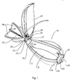
- a fish-bait discharger 10 comprises an elongate streamlined hollow fish-bait container 12.
- the latter has a rounded nose portion 14 and tapers towards its rear tail portion 16.
- the general shape of the container is generally globular at its forward end and tapers towards its rear end. This provides advantageous aerodynamic properties for the discharger 10, and improves the ease with which it can be cast.
- the container comprises an elongate main part 18 which extends from the nose portion 14 to the tail portion 16 of the container, and an elongate lid 20 which also extends from the nose portion 14 to the tail portion 16.
- the rear end of the lid 20 is provided with two trunnions 22 between which are sandwiched trunnions 24 at the tail end of the main part 18.
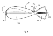
- a pivot pin 26 extends laterally of the container through respective central holes in the trunnions 22 and 24 to create a hinge 27 for the lid whereby it can pivot about that hinge 27 between an open position as shown in Figure 1 to a closed position as shown for example in Figure 3 .
- a torsion spring 28 with an arm 30 is provided to spring-load the lid 20 towards its open position.
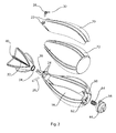
- a separate tail part 32 is provided with an axially extending recess 34 which receives an axially extending rearwardly projecting spigot 36 at the tail end of the main part 18 of the container .12.
- the tail end part 32 comprises four flight fins 38 equally-angularly spaced about a longitudinal central axis of the discharger 10.
- the hinge 27 is therefore located forwardly of the fins 38.
- a swivel 40 is provided at the rear end of the tail end 32 to enable the discharger to be attached to a casting line.
- the tail-end part is formed with an air-filled hollow axially extending portion 41.
- the lid is provided with location pips 39 on its periphery which engage with corresponding portions of the periphery of the main part 18 when the lid 20 is closed to reduce the likelihood of the lid 20 being sheared out of alignment with the main part 18.
- the nose portion 14 of the container 12 is provided with an impact sensitive release mechanism 42.
- the latter comprises a plunger 44 which has a rounded disc-shaped portion 46 which around its periphery continues the streamlined rounded shape of the container 12 at its nose portion 14, but which has a forwardly protruding central circular portion 47.
- the release mechanism 42 further comprises a central axially extending spigot 48 integral with the disc-shaped portion 46, a cylindrical portion 50 surrounding but spaced from the spigot 48 and also integral with the disc-shaped portion 46, leg portions 52 extending rearwardly from the rim of the disc-shaped portion 46, and annular flange portions 54 extending outwardly respectively from those ends of the leg portions 52 which are further from the disc-shaped portion 46.
- the flange portion 54 which is closest to the lid 20 is provided with a snap-action lip 56 provided with an outwardly facing inclined surface 58.
- angle ⁇ is defined as the angle by which the main part 18 of the container 12 surrounds the central longitudinal axis of the discharger 10, at a given position along that axis
- Figure 4 shows the angle ⁇ at the position therealong at which the container 12 has its greatest diameter. It can be seen that the angle ⁇ varies as a function of position along that axis of the discharger 10. At the nose of the container 12, adjacent to the plunger 44, it is at its greatest, being about 1.6 ⁇ radians.
- a transverse membrane or wall 60 extends across the container 12 at the nose end 14 thereof to form a seal between the bait receiving interior of the container 12 and the release mechanism 42 to isolate the former from the latter.
- a cylindrical portion 62 integral with the wall 60 extends centrally and forwardly thereof and receives and acts as a guide for the spigot 48 of the plunger 42.
- a helical spring 64 extends between the wall 60 and the plunger 42 between the cylindrical portions 62 and 50, to urge the plunger in an outward direction. Shoulder portions 66 of the main part 18 of the container 12 engage the flange portions 54 to hold the plunger 42 against the action of a spring 64.
- the curved edges around the outside of the lid 20 correspond to the curved edges of the main part 18, to form a good closure therewith, so that together, with the lid 20 in its closed position, these parts define a streamlined shape of the container 12, the outside of which is generated by rotation of an axially extending line on its surface about its longitudinal axis.
- the nose end of the lid 20 is provided with an inwardly directed lip portion 68 having an inwardly directed inclined surface 70.
- the rear end of the main body 18 is provided with a buffer 72 to limit the extent to which the lid 20 can swing away from the main body 18 and thereby reduce the likelihood of damage thereto.
- the tail end of the main part 18 of the container 12 is grasped by the user, and the main part 18 of the container is used as a scoop to scoop up fish-bait from a pot of such bait (not shown).
- a full scoop 72 some of the bait will project above the main part 18 of the container 12 so that when the lid 20 is brought down upon the main part 18 of the container 12 to close the latter against the action of the spring 28, excess bait is squeezed out between the main part 18 and the lid 20 as the nose end of the lid 20 approaches the release mechanism 42, with a minimal amount being trapped between the main part 18 of the container and the lid 20 because of the relatively thin walls of these two parts.
- the incline 70 of the latching portion 68 rides up the incline 58 of the snap action lip 56 as the latter along with the whole of the plunger 42 is urged inwardly by such closing action against the helical spring 64.
- the plunger 42 snaps upwardly by the action of the spring 64 to trap the latching portion 68 underneath the lip portion 56, and so retain the lid 20 against being opened by the spring 28.
- the latching portion 68 and portions of the main part 18 at opposite ends of the incline 58 constitute a keying which also reduces the likelihood of the lid 20 being sheared out of alignment with the main part 18.
- a casting line end is tied to the swivel 40, the casting line being secured to a fishing rod which is used to cast the discharger 10 into the region of water which is to be baited.
- the combination of its fins 38 and the streamlined shape of the container 12 causes it to fly through the air nose first.
- the plunger 42 strikes the surface of the water first, and this sudden increase in the resistance to motion of the plunger 42 causes it to be depressed into the discharger 10 against the action of the helical spring 64.
- the end edge of the lip 56 passes beyond the end edge of the latching portion 68 so that the lid 20 is released by the release mechanism 42.
- the arm 30 of the spring 28 urges the lid 20 to pivot about its pivot 26 into the open position it has as shown in Figure 1 , but in this case with the main part 18 of the container 12 underneath the water so that the bait that had been contained within the container 12 is discharged into the water.
- the interior of the release mechanism 42 is substantially totally enclosed, reducing the likelihood of it being fouled and made inoperative by extraneous bait or dirt.
- the ratio of the size of the main part 18 to that of the lid 20 in the illustrated construction is substantially 70:30, but other relative sizes are possible.
- the hinge of the lid 20 may be moved forwardly relative to the position it has as shown in Figure 1 , with portions of the main part 18 of the container 12 completely surrounding the longitudinal axis of the discharger 10 at positions rearwardly of the resulting hinge position.
- the lid 20 may be made integrally with the main part 18, but with a thinned portion of plastics material linking the two parts together, which thinned portion is sufficiently flexible to act as a pivot or "living hinge".
- a pivoted triggering member could be provided, using a torsion spring or an elastic member to bias such a pivoted member in the forward direction.
- the pips 39 could be provided on the main part 18, to engage the lid 20 when the latter is closed, instead of on the lid 20.
- Drainage holes may be provided in the main body 18 of the discharger to facilitate discharge of the bait therefrom and/or the escape of water thereform.
- the discharger 10 floats on its side, but other potential orientations are possible with suitable modifications, for example with its fins up and nose down, or flat with its lid down and submerged.
Landscapes
- Life Sciences & Earth Sciences (AREA)
- Environmental Sciences (AREA)
- Animal Husbandry (AREA)
- Biodiversity & Conservation Biology (AREA)
Priority Applications (2)
| Application Number | Priority Date | Filing Date | Title |
|---|---|---|---|
| RS20181347A RS58123B1 (sr) | 2013-12-20 | 2014-11-14 | Otpuštač mamca za ribe |
| PL14003856T PL2893805T3 (pl) | 2013-12-20 | 2014-11-14 | Urządzenie uwalniające zanętę na ryby |
Applications Claiming Priority (1)
| Application Number | Priority Date | Filing Date | Title |
|---|---|---|---|
| GB201322700A GB201322700D0 (en) | 2013-12-20 | 2013-12-20 | A fish-bait discharger |
Publications (3)
| Publication Number | Publication Date |
|---|---|
| EP2893805A2 true EP2893805A2 (de) | 2015-07-15 |
| EP2893805A3 EP2893805A3 (de) | 2015-12-23 |
| EP2893805B1 EP2893805B1 (de) | 2018-10-10 |
Family
ID=50071240
Family Applications (1)
| Application Number | Title | Priority Date | Filing Date |
|---|---|---|---|
| EP14003856.3A Active EP2893805B1 (de) | 2013-12-20 | 2014-11-14 | Fischköderspender |
Country Status (4)
| Country | Link |
|---|---|
| EP (1) | EP2893805B1 (de) |
| GB (1) | GB201322700D0 (de) |
| PL (1) | PL2893805T3 (de) |
| RS (1) | RS58123B1 (de) |
Cited By (3)
| Publication number | Priority date | Publication date | Assignee | Title |
|---|---|---|---|---|
| GB2561033A (en) * | 2017-03-28 | 2018-10-03 | Bvg Group Ltd | Fish bait dispenser |
| GB2610623A (en) * | 2021-09-13 | 2023-03-15 | B P Milling Ltd | Bait dispenser and method of use thereof |
| EP4282264A1 (de) * | 2022-05-27 | 2023-11-29 | Martin Radek | Vorrichtung zum giessen von ködern beim fischen |
Citations (1)
| Publication number | Priority date | Publication date | Assignee | Title |
|---|---|---|---|---|
| WO2009098507A1 (en) | 2008-02-04 | 2009-08-13 | Bryan Gary Houghton | Bait dispenser |
Family Cites Families (6)
| Publication number | Priority date | Publication date | Assignee | Title |
|---|---|---|---|---|
| GB2019181B (en) * | 1978-04-25 | 1982-06-16 | Thwaites E E | Fishing weights |
| JPS61197877U (de) * | 1985-06-03 | 1986-12-10 | ||
| GB9517648D0 (en) * | 1995-08-30 | 1995-11-01 | Cooper Leslie J | Bait discharge missile |
| JP4266473B2 (ja) * | 2000-01-20 | 2009-05-20 | 株式会社シマノ | 撒き餌かご |
| GB2432768B (en) * | 2005-12-02 | 2010-01-06 | Ferris Tech Ltd | Improved Fishing feeder |
| GB201206304D0 (en) * | 2012-04-10 | 2012-05-23 | Houghton Bryan G | Bait dispenser |
-
2013
- 2013-12-20 GB GB201322700A patent/GB201322700D0/en not_active Ceased
-
2014
- 2014-11-14 PL PL14003856T patent/PL2893805T3/pl unknown
- 2014-11-14 RS RS20181347A patent/RS58123B1/sr unknown
- 2014-11-14 EP EP14003856.3A patent/EP2893805B1/de active Active
Patent Citations (1)
| Publication number | Priority date | Publication date | Assignee | Title |
|---|---|---|---|---|
| WO2009098507A1 (en) | 2008-02-04 | 2009-08-13 | Bryan Gary Houghton | Bait dispenser |
Cited By (5)
| Publication number | Priority date | Publication date | Assignee | Title |
|---|---|---|---|---|
| GB2561033A (en) * | 2017-03-28 | 2018-10-03 | Bvg Group Ltd | Fish bait dispenser |
| GB2610623A (en) * | 2021-09-13 | 2023-03-15 | B P Milling Ltd | Bait dispenser and method of use thereof |
| EP4282264A1 (de) * | 2022-05-27 | 2023-11-29 | Martin Radek | Vorrichtung zum giessen von ködern beim fischen |
| HRP20220697A1 (hr) * | 2022-05-27 | 2023-12-08 | Martin Radek | Naprava za bacanje mamaca u ribolovu |
| HRP20220697B1 (hr) * | 2022-05-27 | 2025-09-26 | Martin Radek | Naprava za bacanje mamaca u ribolovu |
Also Published As
| Publication number | Publication date |
|---|---|
| GB201322700D0 (en) | 2014-02-05 |
| EP2893805B1 (de) | 2018-10-10 |
| PL2893805T3 (pl) | 2019-02-28 |
| RS58123B1 (sr) | 2019-02-28 |
| EP2893805A3 (de) | 2015-12-23 |
Similar Documents
| Publication | Publication Date | Title |
|---|---|---|
| CN102753016A (zh) | 饵料投放器 | |
| EP2893805B1 (de) | Fischköderspender | |
| CN101969762B (zh) | 饵料投放器 | |
| US3163957A (en) | Bait casting device | |
| US20110005120A1 (en) | Bow Fishing Rod | |
| RU2679358C1 (ru) | Устройство для разбрасывания приманки для применения в рыбной ловле | |
| EP2836067A1 (de) | Köderspender | |
| US9288974B2 (en) | Shot applicator device | |
| WO2013108012A1 (en) | Bait dispenser | |
| AU756476B1 (en) | A fishing accessory that can be a float or a sinker | |
| JP7546914B2 (ja) | 浮釣り遠投カゴ | |
| US6508683B1 (en) | Line throwing device | |
| GB2113511A (en) | Bait dispenser | |
| US20100011652A1 (en) | Self-Propelled Cast Fishing System | |
| US20100037510A1 (en) | Float device | |
| JP6223299B2 (ja) | 引き舟 | |
| JP5496694B2 (ja) | 釣り糸に沿って移動可能な浮き | |
| WO2001082691A1 (en) | Fish food dispenser for fishing | |
| FR2560005A1 (fr) | Perfectionnement au scion des cannes a peche | |
| EP4282264A1 (de) | Vorrichtung zum giessen von ködern beim fischen | |
| WO2018224820A1 (en) | Bait dispenser | |
| EP3522703B1 (de) | Köderspender | |
| EP2292090A1 (de) | Vorrichtung zum Verteilen von Fischköder in einem Körper mit Wasser | |
| GB2472990A (en) | Fish bait dispenser | |
| JP2578193Y2 (ja) | クランクベイトルアー |
Legal Events
| Date | Code | Title | Description |
|---|---|---|---|
| PUAI | Public reference made under article 153(3) epc to a published international application that has entered the european phase |
Free format text: ORIGINAL CODE: 0009012 |
|
| 17P | Request for examination filed |
Effective date: 20141114 |
|
| AK | Designated contracting states |
Kind code of ref document: A2 Designated state(s): AL AT BE BG CH CY CZ DE DK EE ES FI FR GB GR HR HU IE IS IT LI LT LU LV MC MK MT NL NO PL PT RO RS SE SI SK SM TR |
|
| AX | Request for extension of the european patent |
Extension state: BA ME |
|
| PUAL | Search report despatched |
Free format text: ORIGINAL CODE: 0009013 |
|
| AK | Designated contracting states |
Kind code of ref document: A3 Designated state(s): AL AT BE BG CH CY CZ DE DK EE ES FI FR GB GR HR HU IE IS IT LI LT LU LV MC MK MT NL NO PL PT RO RS SE SI SK SM TR |
|
| AX | Request for extension of the european patent |
Extension state: BA ME |
|
| RIC1 | Information provided on ipc code assigned before grant |
Ipc: A01K 91/06 20060101ALI20151113BHEP Ipc: A01K 97/02 20060101AFI20151113BHEP |
|
| R17P | Request for examination filed (corrected) |
Effective date: 20160623 |
|
| RBV | Designated contracting states (corrected) |
Designated state(s): AL AT BE BG CH CY CZ DE DK EE ES FI FR GB GR HR HU IE IS IT LI LT LU LV MC MK MT NL NO PL PT RO RS SE SI SK SM TR |
|
| RAP1 | Party data changed (applicant data changed or rights of an application transferred) |
Owner name: FOX INTERNATIONAL GROUP LIMITED |
|
| TPAC | Observations filed by third parties |
Free format text: ORIGINAL CODE: EPIDOSNTIPA |
|
| TPAA | Information related to observations by third parties modified |
Free format text: ORIGINAL CODE: EPIDOSCTIPA |
|
| GRAP | Despatch of communication of intention to grant a patent |
Free format text: ORIGINAL CODE: EPIDOSNIGR1 |
|
| STAA | Information on the status of an ep patent application or granted ep patent |
Free format text: STATUS: GRANT OF PATENT IS INTENDED |
|
| INTG | Intention to grant announced |
Effective date: 20180621 |
|
| GRAJ | Information related to disapproval of communication of intention to grant by the applicant or resumption of examination proceedings by the epo deleted |
Free format text: ORIGINAL CODE: EPIDOSDIGR1 |
|
| STAA | Information on the status of an ep patent application or granted ep patent |
Free format text: STATUS: REQUEST FOR EXAMINATION WAS MADE |
|
| GRAP | Despatch of communication of intention to grant a patent |
Free format text: ORIGINAL CODE: EPIDOSNIGR1 |
|
| STAA | Information on the status of an ep patent application or granted ep patent |
Free format text: STATUS: GRANT OF PATENT IS INTENDED |
|
| INTC | Intention to grant announced (deleted) | ||
| GRAS | Grant fee paid |
Free format text: ORIGINAL CODE: EPIDOSNIGR3 |
|
| GRAA | (expected) grant |
Free format text: ORIGINAL CODE: 0009210 |
|
| STAA | Information on the status of an ep patent application or granted ep patent |
Free format text: STATUS: THE PATENT HAS BEEN GRANTED |
|
| INTG | Intention to grant announced |
Effective date: 20180821 |
|
| AK | Designated contracting states |
Kind code of ref document: B1 Designated state(s): AL AT BE BG CH CY CZ DE DK EE ES FI FR GB GR HR HU IE IS IT LI LT LU LV MC MK MT NL NO PL PT RO RS SE SI SK SM TR |
|
| REG | Reference to a national code |
Ref country code: GB Ref legal event code: FG4D |
|
| REG | Reference to a national code |
Ref country code: CH Ref legal event code: EP Ref country code: AT Ref legal event code: REF Ref document number: 1050154 Country of ref document: AT Kind code of ref document: T Effective date: 20181015 |
|
| REG | Reference to a national code |
Ref country code: IE Ref legal event code: FG4D |
|
| REG | Reference to a national code |
Ref country code: DE Ref legal event code: R096 Ref document number: 602014033628 Country of ref document: DE |
|
| REG | Reference to a national code |
Ref country code: NL Ref legal event code: FP |
|
| REG | Reference to a national code |
Ref country code: LT Ref legal event code: MG4D |
|
| PG25 | Lapsed in a contracting state [announced via postgrant information from national office to epo] |
Ref country code: ES Free format text: LAPSE BECAUSE OF FAILURE TO SUBMIT A TRANSLATION OF THE DESCRIPTION OR TO PAY THE FEE WITHIN THE PRESCRIBED TIME-LIMIT Effective date: 20181010 Ref country code: LT Free format text: LAPSE BECAUSE OF FAILURE TO SUBMIT A TRANSLATION OF THE DESCRIPTION OR TO PAY THE FEE WITHIN THE PRESCRIBED TIME-LIMIT Effective date: 20181010 Ref country code: NO Free format text: LAPSE BECAUSE OF FAILURE TO SUBMIT A TRANSLATION OF THE DESCRIPTION OR TO PAY THE FEE WITHIN THE PRESCRIBED TIME-LIMIT Effective date: 20190110 Ref country code: IS Free format text: LAPSE BECAUSE OF FAILURE TO SUBMIT A TRANSLATION OF THE DESCRIPTION OR TO PAY THE FEE WITHIN THE PRESCRIBED TIME-LIMIT Effective date: 20190210 Ref country code: BG Free format text: LAPSE BECAUSE OF FAILURE TO SUBMIT A TRANSLATION OF THE DESCRIPTION OR TO PAY THE FEE WITHIN THE PRESCRIBED TIME-LIMIT Effective date: 20190110 Ref country code: FI Free format text: LAPSE BECAUSE OF FAILURE TO SUBMIT A TRANSLATION OF THE DESCRIPTION OR TO PAY THE FEE WITHIN THE PRESCRIBED TIME-LIMIT Effective date: 20181010 Ref country code: HR Free format text: LAPSE BECAUSE OF FAILURE TO SUBMIT A TRANSLATION OF THE DESCRIPTION OR TO PAY THE FEE WITHIN THE PRESCRIBED TIME-LIMIT Effective date: 20181010 Ref country code: LV Free format text: LAPSE BECAUSE OF FAILURE TO SUBMIT A TRANSLATION OF THE DESCRIPTION OR TO PAY THE FEE WITHIN THE PRESCRIBED TIME-LIMIT Effective date: 20181010 |
|
| PG25 | Lapsed in a contracting state [announced via postgrant information from national office to epo] |
Ref country code: SE Free format text: LAPSE BECAUSE OF FAILURE TO SUBMIT A TRANSLATION OF THE DESCRIPTION OR TO PAY THE FEE WITHIN THE PRESCRIBED TIME-LIMIT Effective date: 20181010 Ref country code: AL Free format text: LAPSE BECAUSE OF FAILURE TO SUBMIT A TRANSLATION OF THE DESCRIPTION OR TO PAY THE FEE WITHIN THE PRESCRIBED TIME-LIMIT Effective date: 20181010 Ref country code: GR Free format text: LAPSE BECAUSE OF FAILURE TO SUBMIT A TRANSLATION OF THE DESCRIPTION OR TO PAY THE FEE WITHIN THE PRESCRIBED TIME-LIMIT Effective date: 20190111 Ref country code: PT Free format text: LAPSE BECAUSE OF FAILURE TO SUBMIT A TRANSLATION OF THE DESCRIPTION OR TO PAY THE FEE WITHIN THE PRESCRIBED TIME-LIMIT Effective date: 20190210 |
|
| REG | Reference to a national code |
Ref country code: CH Ref legal event code: PL |
|
| REG | Reference to a national code |
Ref country code: DE Ref legal event code: R097 Ref document number: 602014033628 Country of ref document: DE |
|
| PG25 | Lapsed in a contracting state [announced via postgrant information from national office to epo] |
Ref country code: DK Free format text: LAPSE BECAUSE OF FAILURE TO SUBMIT A TRANSLATION OF THE DESCRIPTION OR TO PAY THE FEE WITHIN THE PRESCRIBED TIME-LIMIT Effective date: 20181010 Ref country code: LU Free format text: LAPSE BECAUSE OF NON-PAYMENT OF DUE FEES Effective date: 20181114 |
|
| PLBE | No opposition filed within time limit |
Free format text: ORIGINAL CODE: 0009261 |
|
| STAA | Information on the status of an ep patent application or granted ep patent |
Free format text: STATUS: NO OPPOSITION FILED WITHIN TIME LIMIT |
|
| REG | Reference to a national code |
Ref country code: IE Ref legal event code: MM4A |
|
| PG25 | Lapsed in a contracting state [announced via postgrant information from national office to epo] |
Ref country code: SK Free format text: LAPSE BECAUSE OF FAILURE TO SUBMIT A TRANSLATION OF THE DESCRIPTION OR TO PAY THE FEE WITHIN THE PRESCRIBED TIME-LIMIT Effective date: 20181010 Ref country code: RO Free format text: LAPSE BECAUSE OF FAILURE TO SUBMIT A TRANSLATION OF THE DESCRIPTION OR TO PAY THE FEE WITHIN THE PRESCRIBED TIME-LIMIT Effective date: 20181010 Ref country code: SM Free format text: LAPSE BECAUSE OF FAILURE TO SUBMIT A TRANSLATION OF THE DESCRIPTION OR TO PAY THE FEE WITHIN THE PRESCRIBED TIME-LIMIT Effective date: 20181010 Ref country code: CH Free format text: LAPSE BECAUSE OF NON-PAYMENT OF DUE FEES Effective date: 20181130 Ref country code: EE Free format text: LAPSE BECAUSE OF FAILURE TO SUBMIT A TRANSLATION OF THE DESCRIPTION OR TO PAY THE FEE WITHIN THE PRESCRIBED TIME-LIMIT Effective date: 20181010 Ref country code: LI Free format text: LAPSE BECAUSE OF NON-PAYMENT OF DUE FEES Effective date: 20181130 Ref country code: MC Free format text: LAPSE BECAUSE OF FAILURE TO SUBMIT A TRANSLATION OF THE DESCRIPTION OR TO PAY THE FEE WITHIN THE PRESCRIBED TIME-LIMIT Effective date: 20181010 |
|
| 26N | No opposition filed |
Effective date: 20190711 |
|
| PG25 | Lapsed in a contracting state [announced via postgrant information from national office to epo] |
Ref country code: SI Free format text: LAPSE BECAUSE OF FAILURE TO SUBMIT A TRANSLATION OF THE DESCRIPTION OR TO PAY THE FEE WITHIN THE PRESCRIBED TIME-LIMIT Effective date: 20181010 Ref country code: IE Free format text: LAPSE BECAUSE OF NON-PAYMENT OF DUE FEES Effective date: 20181114 |
|
| PG25 | Lapsed in a contracting state [announced via postgrant information from national office to epo] |
Ref country code: MT Free format text: LAPSE BECAUSE OF NON-PAYMENT OF DUE FEES Effective date: 20181114 |
|
| PG25 | Lapsed in a contracting state [announced via postgrant information from national office to epo] |
Ref country code: TR Free format text: LAPSE BECAUSE OF FAILURE TO SUBMIT A TRANSLATION OF THE DESCRIPTION OR TO PAY THE FEE WITHIN THE PRESCRIBED TIME-LIMIT Effective date: 20181010 |
|
| PG25 | Lapsed in a contracting state [announced via postgrant information from national office to epo] |
Ref country code: MK Free format text: LAPSE BECAUSE OF NON-PAYMENT OF DUE FEES Effective date: 20181010 Ref country code: CY Free format text: LAPSE BECAUSE OF FAILURE TO SUBMIT A TRANSLATION OF THE DESCRIPTION OR TO PAY THE FEE WITHIN THE PRESCRIBED TIME-LIMIT Effective date: 20181010 Ref country code: HU Free format text: LAPSE BECAUSE OF FAILURE TO SUBMIT A TRANSLATION OF THE DESCRIPTION OR TO PAY THE FEE WITHIN THE PRESCRIBED TIME-LIMIT; INVALID AB INITIO Effective date: 20141114 |
|
| REG | Reference to a national code |
Ref country code: AT Ref legal event code: UEP Ref document number: 1050154 Country of ref document: AT Kind code of ref document: T Effective date: 20181010 |
|
| PGFP | Annual fee paid to national office [announced via postgrant information from national office to epo] |
Ref country code: NL Payment date: 20251114 Year of fee payment: 12 |
|
| PGFP | Annual fee paid to national office [announced via postgrant information from national office to epo] |
Ref country code: DE Payment date: 20251114 Year of fee payment: 12 |
|
| PGFP | Annual fee paid to national office [announced via postgrant information from national office to epo] |
Ref country code: GB Payment date: 20251119 Year of fee payment: 12 |
|
| PGFP | Annual fee paid to national office [announced via postgrant information from national office to epo] |
Ref country code: AT Payment date: 20251114 Year of fee payment: 12 |
|
| PGFP | Annual fee paid to national office [announced via postgrant information from national office to epo] |
Ref country code: IT Payment date: 20251114 Year of fee payment: 12 |
|
| PGFP | Annual fee paid to national office [announced via postgrant information from national office to epo] |
Ref country code: FR Payment date: 20251125 Year of fee payment: 12 |
|
| PGFP | Annual fee paid to national office [announced via postgrant information from national office to epo] |
Ref country code: BE Payment date: 20251114 Year of fee payment: 12 |
|
| PGFP | Annual fee paid to national office [announced via postgrant information from national office to epo] |
Ref country code: CZ Payment date: 20251104 Year of fee payment: 12 |
|
| PGFP | Annual fee paid to national office [announced via postgrant information from national office to epo] |
Ref country code: PL Payment date: 20251113 Year of fee payment: 12 |
|
| PGFP | Annual fee paid to national office [announced via postgrant information from national office to epo] |
Ref country code: RS Payment date: 20251105 Year of fee payment: 12 |